transmission level hts fault current limiter performance. powerful technology. superpower, inc. is a...
TRANSCRIPT

superior performance.powerful technology.
SuperPower, Inc. is a subsidiary of Royal Philips Electronics N.V.
Transmission Level HTS Fault Current Limiter
Dr. Juan-Carlos LlambesC.S. Weber, D.W. Hazelton, M. Marchevsky, Y.Y. Xie, V. Selvamanickam
Applied Superconductivity Conference (Session 4LY07)Chicago, Illinois August 21, 2008

2008 US DOE Peer Review – July 29-31, 2008
SFCL program overview
15.248"
7.362"
15.248"
7.362"
138 kV, 650 kV BIL Bushings
Vacuum Vessel
Pressure Vessel
Matrix Assembly
Inner diameter
Inner Height
HTS Assembly Height
Assembly diameter
Partners
Specifications
• YBCO based, resistive type FCL• 138 kV class device• Fault Current – 13.8 kA• Load Current – 1,200 Arms• Design fault current – 37 kA• Design device response – Recover
to superconducting state after a fault carrying full load current

2008 US DOE Peer Review – July 29-31, 2008
Prior accomplishments
• Proof-of-Concept demonstrated– MCP 2212 (2004)– 2G YBCO (2006)
• Beta device testing specifications established
• Completed design and testing of HV bushings (SEI)
• Investigated several ‘engineered’ 2G architectures for improved RUL
• Design and laboratory testing of shunt coils to withstand high fault transient loads
• Thermal simulation of RUL process• Weibull plots of ‘standard’ 2G failures• Conceptual CRS & vessel design• Investigated LN2 dielectric properties
2G FCL - Probability of failure for 2G tapes as function of energy input
0.01
0.1
1
10
100
20 25 30 35 40 45 50
Energy [J/cm/tape]
Prob
abilit
y of
failu
re [%
]
Probability of Failure - Test dataProbability of Failure Calculated using Weibull Distributuon

2008 US DOE Peer Review – July 29-31, 2008
Improvements to shunt coil and contact design
• Shunt coil improvements:– Manufacturing improvements
(easier assembly, more robust coil)
– Mechanical strength – Multi-Layer winding (size
reduction)• Connector improvements:
– Shape optimization to avoid contact hotspots
– Improvement in RUL Time– Improvement in RUL Current– Improvement in consistency of
contact resistance

2008 US DOE Peer Review – July 29-31, 2008
Tape heating near contact during fault impacts RUL

2008 US DOE Peer Review – July 29-31, 2008
Correlation between different contact geometries
Total Current (80A peak)
Recovery Voltage
Superconductor’s Current
Straight Thick Contacts(M3-460 Tape):I load = 80 A
RUL = 82 sec.
Total Current (80A peak)
Recovery Voltage
Superconductor’s Current
Total Current (80A peak)
Recovery Voltage
Superconductor’s Current
Straight α-Tapered Contacts(M3-460 Tape):
I load = 80 A RUL = 3.5 sec.
Straight β-Tapered Contacts(M3-460 Tape):
I load = 80 A RUL = 2.8 sec.

2008 US DOE Peer Review – July 29-31, 2008
Recent KEMA tests• Recent rounds of KEMA testing focused on critical AEP reclosure sequence on
an HTS element
• Straight elements were used
• Improved connector designs were used
• “Standard”, pre-qualified tapes were used
• Test Dates: May 2008, July 2008
5 CyclesFault
13kA/7kA
18 Cycles Load Current
15 sec Load Current
135 sec Load Current
5 CyclesFault
13kA/7kA
5 CyclesFault
13kA/7kA
5 CyclesFault
13kA/7kA
Breaker opens and locks-out
Recovery under NO Load Current
5 CyclesFault
13kA/7kA
160 sec Load Current

2008 US DOE Peer Review – July 29-31, 2008
2G RUL capabilities tested at KEMA
• ‘Standard’ SC12100 2G wire used
• Test conditions- 37 kA fault
- follows AEP sequence
• Test variables- Shunt impedance
- Number of parallel tapes
- System voltage (v/cm/tape)
- Load Current
16 Tapes8 Tapes
4 Tapes100V
200V
250V
300V
0
50000
100000
150000
200000
250000
Load Pow er (VA)
Total Recovered Power, 2x5 cycles Faults at 37kA with 10 mOhm
Parallel Tapes
Voltag
e
2008 US DOE Peer Review – July 29-31, 2008
3 x Base-Line Voltage
w/o Load
w/ Load
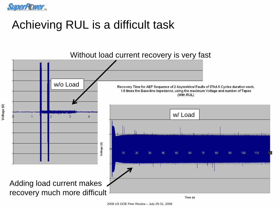
Achieving RUL is a difficult task
Without load current recovery is very fast
Adding load current makes recovery much more difficult

2008 US DOE Peer Review – July 29-31, 2008
Base-Line Voltage
RUL
1.5 x Base-Line Voltage
RUL
3 x Base-Line Voltage
RUL
Electrical stress on the tapes can limit RUL
• RUL time can affected by increasing the V/cm on the tape
• Limits of the design optimization are understood

2008 US DOE Peer Review – July 29-31, 2008
Factors impacting RUL defined by test results
1.67 m-Ohm
5 m-Ohm
100 V200 V
250 V300 V
0
10000
20000
30000
40000
50000
60000
70000
80000
Load Power (VA))
Total Recovered Power, 2x5 cycles Faults at 37kA with 4 Tapes
Shunt ImpedanceVoltage
Sample surface plot of RUL conditions

2008 US DOE Peer Review – July 29-31, 2008
Ability to predict RUL over wide design space
1.67
m-O
hm
5 m
-Ohm
4Tap
es, 1
00V
4Tap
es, 2
50V
8Tap
es, 1
00V
8Tap
es, 2
50V
16Ta
pes,
100
V
16Ta
pes,
250
V
0100200300
400500
600
700
800
900
1000
Maximun Recovered Load Current
Recovered Current with 2 Asymmetrical 37kA Faults, 5 cycles each
ImpedanceVoltage, #Tapes
Maximum Load Current as a function of shunt impedance, operating voltage & number of tapes

2008 US DOE Peer Review – July 29-31, 2008
RUL with 90% of the Power recovered within the 2nd and the 3rd 37 kA Faults
Worst case conditions at Tidd can achieve RUL
Full recovery expected with optimal bath conditions

2008 US DOE Peer Review – July 29-31, 2008
Thank You for your attention!
For more information:
www.superpower-inc.comor