translation of the original instructions - ief-werner€¦ · translation of the original...
TRANSCRIPT

October 2012 Translation of the original instructions MAN_EN_1040588_Modul80-15_R5d.doc Module 80/15 Page 1 of 39
IEF Werner GmbH Wendelhofstraße 6
78120 Furtwangen - Germany Phone: +49 7723-925-0 Fax: +49 7723-925-100
www.IEF-Werner.de [email protected]
Translation of the original instructions
Module 80/15
Issue: October 2012
Article no.: 1040588

Translation of the original instructions October 2012 Page 2 of 39 Module 80/15 MAN_EN_1040588_Modul80-15_R5d.doc
Change History:
Trademarks and trade names are used without any warranty of their free usability Texts and examples were created with great care. Nevertheless, errors cannot be excluded. IEF Werner GmbH does not assume legal responsibility nor any liability for missing or incorrect statements and their consequences.
IEF Werner GmbH reserves the right to modify or improve the software or hardware or parts of it, as well as the supplied documentation or parts of it, without previous notice.
IEF Werner GmbH expressly reserves all rights for replication and photomechanical reproduction, including in extracts.
We are always grateful for suggestions for improvements and information about errors.
© October 2012, IEF Werner GmbH
Document Code Date Revision
EN_1040588_Modul 80-15_R5b.doc April 2006 New table with planetary gear boxes, external greasing
MAN_EN_1040588_Modul 80-15_R5c.doc January 2007 Replaced coupler for parallel drive
MAN_EN_1040588_Modul80-15_R5d.doc 2012-10-10 Changes as for as parts number are concerned (sections 7.1, 7.2, 7.3). Adaption to German document (“MAN_DE_1040587_Modul80-15_R7b/c.doc”).

October 2012 Translation of the original instructions MAN_EN_1040588_Modul80-15_R5d.doc Module 80/15 Page 3 of 39
Table of Contents
1 Safety 5 1.1 Definition or warning notes 5 1.2 General warning notes 5 1.3 Special hazard warnings 6
2 Intended use 7 2.1 Reasonably foreseeable misuse 7
3 Assembly instructions 8 3.1 Installation position 8 3.2 Overview of motor installation variants 8
3.2.1 Module 80/15, installation variant 1 9 3.2.2 Module 80/15, installation variant 5 9
3.3 Attachment 10 3.3.1 Installation of actuators 12
3.4 Wiring 13 3.4.1 Motors 13 3.4.2 Initiators 13
3.4.2.1 Technical data of initiators 14 3.4.2.2 Plug end position switch 15
3.4.3 Cable routing 15 3.5 Technical data 16
3.5.1 Tightening torques for screw connections 16 3.5.2 Technical data of the linear module 80/15 16 3.5.3 Type label 17 3.5.4 Technical data when using a planetary gear 17 3.5.5 Axis distances and tooth numbers 18 3.5.6 Load cases 19
3.5.6.1 Torques and carrying capacities 19 3.5.6.2 Tilting of the carriage unit at lateral load 20
4 Maintenance 21
5 Troubleshooting 22
6 Repair 24 6.1 Factory-setting of the toothed belt tension 25 6.2 Replace toothed belt 26 6.3 Reference side of the guide system 28

Translation of the original instructions October 2012 Page 4 of 39 Module 80/15 MAN_EN_1040588_Modul80-15_R5d.doc
7 Parts lists and drawings 30 7.1 Module 80/15 30 7.2 Carriage module 80/15/195 complete 32 7.3 Long carriage module 80/15/300 PS complete 33 7.4 (Belt) Gearbox module 80/15 34 7.5 Flange 36 7.6 Design-specific assemblies/components 37
7.6.1 Installation flange gearbox (e.g. planetary gear type PLFE64) 37 7.6.2 Overview clamping elements 38
8 Declaration of incorporation 39

October 2012 Translation of the original instructions Safety MAN_EN_1040588_Modul80-15_R5d.doc Module 80/15 Page 5 of 39
1 Safety
1.1 Definition or warning notes
WARNING Indicates potential danger. Non-observance of the safety provisions may cause death or severe injury.
CAUTION Indicates potential danger. Non-observance of the safety provisions may cause property damage or injury.
NOTE Offers additional information.
1.2 General warning notes
The module must only be commissioned by specialists who received safety-technical instruction and are able to assess potential dangers. Furthermore, all chapters of these operating instructions must have been read and understood completely.
WARNING The system must be powered down for all assembly, disassembly or repair work. There is a high danger of injury.
WARNING OF HOT SURFACE During operation, heating of the motor, in particular of stepper motors, can cause burns of the skin when touching the motor. Install a protective device, if possible! Do not touch the marked areas or wait for an adequate cooling time.
CAUTION Motor connectors must not be inserted or disconnected when live. Risk of burning of the contacts and risk of flying sparks.

Safety Translation of the original instructions October 2012 Page 6 of 39 Module 80/15 MAN_EN_1040588_Modul80-15_R5d.doc
CAUTION Linear modules always have to be operated in connection with suitable safety devices (e.g., safety cell, protective room, protective housing, light curtain).
NOTE Observe the Declaration of Incorporation (see section Declaration of incorporation,page 39).
1.3 Special hazard warnings
In addition, this Original User's Manual also contains the following special hazard warning:
DANGER FROM CRUSHING These places of the components pose the danger of crushing limbs in operation.

October 2012 Translation of the original instructions Intended use MAN_EN_1040588_Modul80-15_R5d.doc Module 80/15 Page 7 of 39
2 Intended use
The linear unit module 80/15 (see Figure 1) was designed for use in the commercial area. Use of a high-quality guide warrants high dynamics and good running behaviour. The internal guide system is protected from contamination by the toothed belt. Additionally, the guide elements have special seals that protect the guide tracks from gross contamination. Use of the linear unit module 80/15 under conditions with increased contamination and abrasive dusts, however, should be avoided because there are no further protective measures like bellows, etc.
Figure 1: Module 80/15
When using the linear unit module 80/15, observe that the constructive setup of the linear unit will cause increased lateral tilting of the carriage due to torque occurring. This feature is, however, an essential benefit in setup of a parallel guide system, because it avoids over-determination of the guide system.
If higher torque appears or a higher stiffness is required, in particular in boom systems, the series module 160/15 must be used.
The areas of use for the linear module 80/15 are accordingly diverse. They range from stop adjustment in the wood industry to equipment systems for SMD-components, joining and pressing processes in precision mechanics, loading and unloading stations of tool machines, to manipulators for the packaging industry.
2.1 Reasonably foreseeable misuse
The linear module 80/15 is not to be used for certain applications such as the transport of persons and animals or as a pressing/bending device for cold working of metal.
Use of the linear module without additional measures is also not possible in special fields of application, such as the chemical or food industry or in explosive atmospheres.
In case of doubt, consult the manufacturer.

Assembly instructions Translation of the original instructions October 2012 Page 8 of 39 Module 80/15 MAN_EN_1040588_Modul80-15_R5d.doc
3 Assembly instructions
3.1 Installation position
The installation position is optional, i.e. the linear module 80/15 can be used horizontally as well as vertically.
CAUTION
In the vertical installation position, use only motors with spring-operated brake to prevent the lowering of the drive in de-energized condition!
3.2 Overview of motor installation variants
Figure 2: Installation variants module 80/15
Installation variant 1 Installation variant 2
Installation variant 3 Installation variant 4
Installation variant 5 Installation variant 6

October 2012 Translation of the original instructions Assembly instructions MAN_EN_1040588_Modul80-15_R5d.doc Module 80/15 Page 9 of 39
3.2.1 Module 80/15, installation variant 1
Figure 3: Module 80/15, subassembly number 1000398, installation variant 1
3.2.2 Module 80/15, installation variant 5
Figure 4: Module 80/15, subassembly number 1000398, installation variant 5
A: Reference point A; B: Stroke limited switch
L = Stroke + 424
Stroke + 200
12 +0,1 2 deep (8x)
A: Reference point A; B: Stroke limited switch
L = Stroke + 424
Stroke + 200
12 +0,1 2 deep (8x)
99 mounting dimension
99 mounting dimension

Assembly instructions Translation of the original instructions October 2012 Page 10 of 39 Module 80/15 MAN_EN_1040588_Modul80-15_R5d.doc
3.3 Attachment
In most use cases, the linear module 80/15 is attached to a level mounting surface with clamping profiles/clamping elements (see Figure 5, bottom). The carriage moves freely.
The linear module should not be attached otherwise, e.g. by additional bores in the basic body. These bores will nearly always lead to clamping of the guide basis and damage to internal parts of the module.
CAUTION
The clamping surface should have a levelness of 0.1 mm/m².
Figure 5: Cross-section with clamping elements and dimensions (module 80/15)
NOTE For an overview of the different clamping elements, see the section Overview clamping elements, Page 38.
Clamping element
Clamping element

October 2012 Translation of the original instructions Assembly instructions MAN_EN_1040588_Modul80-15_R5d.doc Module 80/15 Page 11 of 39
DANGER FROM CRUSHING These places of the components pose the danger of crushing limbs.
There is danger of crushing at the start and end of a stroke (see Figure 6).
Figure 6: Possible crushing points
Figure 7 shows the drilling pattern of a standard carriage.
64
± 0
,10
99 ± 0,10
179 ± 0,10
80
195 ± 0,20
M6 (8x)12+0,1
2tief (8x)
Figure 7: Drilling pattern standard carriage
12 +0,1 2 deep (8x)

Assembly instructions Translation of the original instructions October 2012 Page 12 of 39 Module 80/15 MAN_EN_1040588_Modul80-15_R5d.doc
Figure 8 shows the drilling pattern of a long carriage.
80
64 ±
0,0
5
300 -0,2
99 ± 0,1040 ± 0,10
40 ± 0,10
11± 0,10
11 ± 0,10
M6
(12
x)
12+0,1
2 tief (12x)
Figure 8: Drilling pattern long carriage
Figure 9 shows a centring ring to take up clamping elements:
Figure 9: Centring ring (article no.: 1024021)
The threaded bores M6 make different axis configurations possible on the carriage, possibly using an adapter plate.
The recesses Ø12 serve to centre clamping elements with supply option.
3.3.1 Installation of actuators
Actuators to be installed on the linear module (pick-up modules, cylinders) are usually attached to the linear unit using the drill template on the carriage (Figure 7, page 11 and Figure 8, page 12).
12 +0,1 2 deep (12x)

October 2012 Translation of the original instructions Assembly instructions MAN_EN_1040588_Modul80-15_R5d.doc Module 80/15 Page 13 of 39
3.4 Wiring
3.4.1 Motors
CAUTION The electrical connection of the motors is performed according to the motor data sheet. For customer-specific motors, the data sheet must be requested from the respective manufacturer and the motor connected accordingly.
3.4.2 Initiators
Inductive proximity switches (PNP normally closed contacts, article no.: 025165) are used as standard limit switches for the running path (see Figure 10). These switches are no safety limit switches pursuant to EN60204-1. Optionally, (also subsequently) an additional reference point switch (PNP normally open contact article no.: 726744, see Figure 11), can be installed in the linear module 80/15. The active button is marked with a coloured circle. Normally closed contacts are marked with a green, normally open contacts with a red dot. The initiators and their supply lines are protected in a cable channel integrated in the basic body, and are wired to a joint plug.
A plastic strip serves to cover the cable channel. An initiator can be replaced or relocated easily after removal of this plastic strip from the cable channel.
Figure 10: Connection allocation PNP normally closed contact
Figure 11: Connection allocation PNP normally open contact
Assembly instructions Translation of the original instructions October 2012 Page 14 of 39 Module 80/15 MAN_EN_1040588_Modul80-15_R5d.doc
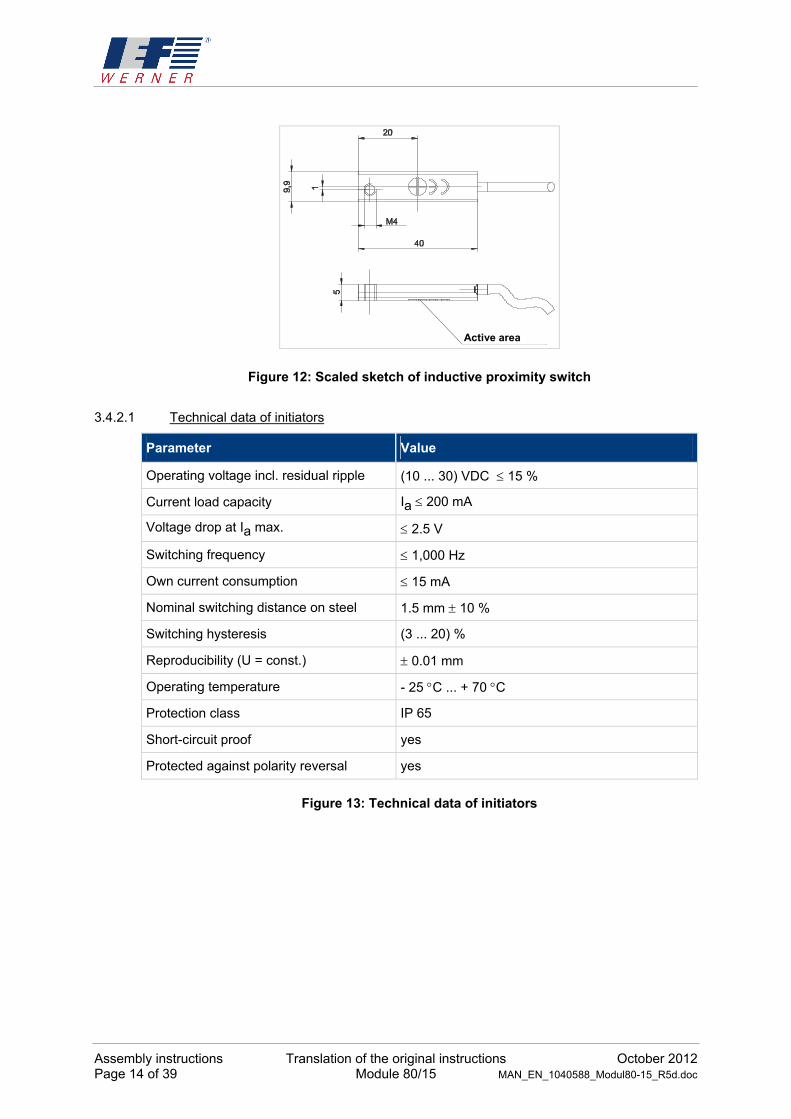
Figure 12: Scaled sketch of inductive proximity switch
3.4.2.1 Technical data of initiators
Parameter Value
Operating voltage incl. residual ripple (10 ... 30) VDC 15 %
Current load capacity Ia 200 mA
Voltage drop at Ia max. 2.5 V
Switching frequency 1,000 Hz
Own current consumption 15 mA
Nominal switching distance on steel 1.5 mm 10 %
Switching hysteresis (3 ... 20) %
Reproducibility (U = const.) 0.01 mm
Operating temperature - 25 C ... + 70 C
Protection class IP 65
Short-circuit proof yes
Protected against polarity reversal yes
Figure 13: Technical data of initiators
Active area

October 2012 Translation of the original instructions Assembly instructions MAN_EN_1040588_Modul80-15_R5d.doc Module 80/15 Page 15 of 39
3.4.2.2 Plug end position switch
The end position switch is assigned as follows (see Figure 14):
Pin-No. Assignment IEF Werner cables
1 + 24 V brown
2 Limit switch negative direction green
3 0 V white
4 Limit switch positive direction yellow
5 Reference switch grey
Figure 14: Connection assignment plug end position switch
3.4.3 Cable routing
For all moving cables, suitable cable routing has to be used to effectively prevent cable breaks.
The minimum radius rmin for cable routing chains is calculated for IEF-Werner cables according to the following formula:
rmin 10 x cable diameter
When different cables are used, EN 60204 must be observed. In addition, it must be ensured that a space reserve of 30% is kept free within the routing chains. A strain relief for the cables has to be attached at the outlet of the cable routing chain.
We recommend to also order cables and cable routing chains at IEF Werner GmbH.

Assembly instructions Translation of the original instructions October 2012 Page 16 of 39 Module 80/15 MAN_EN_1040588_Modul80-15_R5d.doc
3.5 Technical data
3.5.1 Tightening torques for screw connections
Screw 8.8 Tightening torque [Nm]
M3 1,1
M4 2,5
M5 5,0
M6 8,5
M8 21,0
M10 41,0
M12 71,0
Screw 12.9 Tightening torque [Nm]
M4 (guide rail attachment)
4,9
3.5.2 Technical data of the linear module 80/15
Parameter Value
Repeating accuracy +/- 0.05 mm
Weight (without motor at stroke 0 mm) 6.9 kg
Weight increase per 100 mm stroke 0.95 kg
Maximum movement speed 5 m/s
Maximum acceleration 40 m/s²
Max. transferrable infeed force at max. movement speed (5 m/s)
1,278 N
Max. torque Mx 80 Nm
Max. torque My 30 Nm
Max. torque Mz 100 Nm
Carrying capacity C1 1,000 N
Carrying capacity C2 300 N
Guide stiffness x See Tilting of the carriage unit at lateral load, page 20.
Area inertias of the profile cross-section at the centre of gravity:
Ix 570018 mm4
Iy 1,400,047 mm4
Figure 15: Technical data

October 2012 Translation of the original instructions Assembly instructions MAN_EN_1040588_Modul80-15_R5d.doc Module 80/15 Page 17 of 39
3.5.3 Type label
Figure 16: Type label (example)
3.5.4 Technical data when using a planetary gear
Before commissioning, observe the possible input speeds of the gear manufacturers. Too-high input speeds can lead to increased wear at the gear and/or thermal problems.
The accuracy of the linear unit is influenced by the reverse play of the gears.
Example:
The gear reverse play (S) is 9 angle minutes.
How high is the reverse play at the carriage of the linear unit?
Infeed constant of the linear unit (Vk): 140 mm
Reverse play at the carriage = (Vk • S) / (360 x 60)
= (140 mm • 9) / (360 x 60)
= 0.058 mm
Consider the information of the respective gear manufacturer in any case.
e.g. http://www.neugart.de/index.php/de/Produkte/Standardgetriebe
http://www.wittenstein-alpha.de/896.htm
Module 80/15

Assembly instructions Translation of the original instructions October 2012 Page 18 of 39 Module 80/15 MAN_EN_1040588_Modul80-15_R5d.doc
3.5.5 Axis distances and tooth numbers
38
,88
AA21
8,8
8
Figure 17: Explanations on the table axis distances, subassembly no.: 1000475
Comply with the following axis distances in the required standard reductions:
i Z1 drive Z2
output
Drilled hole drive
Length of toothed
belt
AA [mm]
Infeed constant [mm]
1:1 42 42 max.
Ø 32 mm 450 mm 120 140
2,1:1 42 20 max.
Ø 16 mm 390 mm 116,18 66,667
2,625:1 42 16 max.
Ø 14 mm 390 mm 120,73 53,33
3:1 42 14 max.
Ø 12 mm 375 mm 115,35 46,667
Z1
Z2

October 2012 Translation of the original instructions Assembly instructions MAN_EN_1040588_Modul80-15_R5d.doc Module 80/15 Page 19 of 39
3.5.6 Load cases
3.5.6.1 Torques and carrying capacities
Figure 18: Torques and carrying capacities
Excerpt from the technical data (Figure 15, page 16):
Parameter Value
Max. torque Mx 80 Nm
Max. torque My 30 Nm
Max. torque Mz 100 Nm
Carrying capacity C1 1,000 N
Carrying capacity C2 300 N
Figure 19: Table torques and carrying capacities

Assembly instructions Translation of the original instructions October 2012 Page 20 of 39 Module 80/15 MAN_EN_1040588_Modul80-15_R5d.doc
3.5.6.2 Tilting of the carriage unit at lateral load
Figure 20: Tilting of the carriage
Figure 21: Deflection at lateral load
a
b
c

October 2012 Translation of the original instructions Maintenance MAN_EN_1040588_Modul80-15_R5d.doc Module 80/15 Page 21 of 39
4 Maintenance
During the design of the linear module module 80/15, importance was placed on the use of low-maintenance components. All roller elements were provided with lifetime lubrication in the factory.
The guide carriages are equipped with attached lubrication elements. This makes it possible to achieve a running performance of 10000 km with initial lubrication. In single-shift operation, this corresponds to nearly 5 years at a stroke of 500 mm and 20 cycles per minute.
Once the indicated running output is reached, the guide carriage can be re-lubricated with a special grease press (IEF-item no.: 1055123) (see Figure 22 and Figure 23). The grease gun is filled with the high-performance lubricant Dynalub.
NOTE Never use any grease that contains ester oils.
Figure 22: Lubrication of the guide carriage (carriage without external lubrication)
Figure 23: Lubrication of the guide carriage (carriage with external lubrication)

Troubleshooting Translation of the original instructions October 2012 Page 22 of 39 Module 80/15 MAN_EN_1040588_Modul80-15_R5d.doc
5 Troubleshooting
Interference Reason Correction
Nominal service life of guide carriage exceeded
Replace all guide carriages
Guide carriage worn due to overload
(too-high torque, etc.)
Replace all guide carriages, reduce load
Guide carriage worn from strong contamination
Replace all guide carriages, clean guide rails and relubricate
Guide rails worn Replace guide rails, replace all guide carriages, check load, protect linear module from strong contamination
Guide rails corroded Replace all guide rails, replace guide carriages if required
Deflection unit worn Replace deflection unit
Drive unit worn Replace drive unit
Toothed belt runs dry Slightly lubricate toothed belt on the toothed inner side
Toothed belt tension too high Re-set toothed belt tension at the carriage part
Toothed belt runs diagonally Align toothed belt with belt fastener (pressure piece and tooth segment), tighten cylindrical screws M6 evenly!
Toothed belt strongly contaminated on the toothed inner side
Replace toothed belt, protect linear module from strong contamination
Toothed belt defective Replace toothed belt
Motor (motor bearing) defective Replace motor
Increased running noise
For motor with brake: Brake does not disengage
Apply current to the brake, if the brake still does not open, replace motor
Limit switch cable not connected.
Connect the cable
Limit switch defective Replace limit switch
Limit switch cable defective Check limit switch cable
Solder connection on socket has come loose
Solder on wires
Motor connected incorrectly Check and change connector assignment, if required
Linear drive unit does not move
Motor defective Replace motor

October 2012 Translation of the original instructions Troubleshooting MAN_EN_1040588_Modul80-15_R5d.doc Module 80/15 Page 23 of 39
Troubleshooting, continued
Interference Reason Correction
Error in power electronics or control unit
Check the power electronics or the control unit
Motor cable defective Check motor cable, replace cable, if required
For belt gear: Toothed disc slips through
Engage clamp set tightly and secure screws with threadlocker.
For planetary gear: Clutch between motor and planetary gear slips
Engage clutch tightly and secure screws with threadlocker.
Linear drive unit does not move
For motor with brake: Brake does not disengage
Apply current to the brake, if the brake still does not open, replace motor
Gearbox toothed belt not tensioned
Tension gear toothed belt
Motor toothed disk has play (key connection)
Replace motor toothed disc if motor shaft keyway is damaged, replace motor
Play on reversal
Tension drive toothed belt
Incorrect direction of rotation Change motor direction of rotation Linear drive unit moves mechanically against the stop during the reference run
Broken motor cable Replace cable

Repair Translation of the original instructions October 2012 Page 24 of 39 Module 80/15 MAN_EN_1040588_Modul80-15_R5d.doc
6 Repair
WARNING Always power down the system before starting repairs.
WARNING Any repairs must only be performed by specialist personnel who have read and understood the operating instructions.
CAUTION Only use original replacement parts, otherwise IEF Werner GmbH will not accept any warranty.

October 2012 Translation of the original instructions Repair MAN_EN_1040588_Modul80-15_R5d.doc Module 80/15 Page 25 of 39
6.1 Factory-setting of the toothed belt tension
The toothed belt tension of the axial toothed belt is set via adjustment screws (see Figure 24). The toothed belt tension is correctly set at delivery.
Figure 24: Adjustment screws for toothed belt tension
NOTE Do not remove the threadlocker from the adjustment screws.
The belt tension of the gear toothed belt (motor installation variants 1-4) is 150 N.
Adjustment screws

Repair Translation of the original instructions October 2012 Page 26 of 39 Module 80/15 MAN_EN_1040588_Modul80-15_R5d.doc
6.2 Replace toothed belt
Proceed as follows to replace the toothed belt:
NOTE Toothed belt replacement is generally performed the same for the standard and long carriage. The following sections deal with toothed belt replacement at the standard carriage.
(1) Loosen the four attachment screws M6 x 25 (see Figure 25, item 100).
(2) Remove the pressure pieces (see Figure 25, item 30).
100
30
30
100
Figure 25: Loosen attachment screws
(3) Remove the covers (see Figure 26, item 100).
100
100
Figure 26: Remove the covers

October 2012 Translation of the original instructions Repair MAN_EN_1040588_Modul80-15_R5d.doc Module 80/15 Page 27 of 39
(4) Remove the defective toothed belt and insert a new one.
(5) Insert the toothed belt into the tooth segment (see Figure 27, item 20).
(6) Screw the pressure piece tightly on both sides "to block" (see Figure 27, item 100).
100
2020
100
Figure 27: Tooth segment
(7) Install the covers again.
NOTE The belt tension is pre-set in the factory. Do not remove the threadlocker from the retention screws!

Repair Translation of the original instructions October 2012 Page 28 of 39 Module 80/15 MAN_EN_1040588_Modul80-15_R5d.doc
6.3 Reference side of the guide system
The guide rail is aligned on the reference side of the basic body (marked by the 90° groove). The reference side of the carriage plate, marked by two unilateral alignment pins, is on the same side as the reference side of the basic body (see Figure 28).
Figure 28: Reference side
The adapter plate is applied to the two guide carriages on the reference side. In the new condition, the guide carriages are harder to push. After a brief run-in time (1-2 days), the pushing resistance reduces to its regular amount.
NOTE Carriage plate and adapter plate must not be swapped with the carriage plate and adapter plate of other linear units of module 80/15!
Zylinderstift auf Referenzseite ausrichten
Referenzseite der Führungswagen
Bei Montage in diese Richtung drücken
Schiene an Kante anschlagen
Referenzmarkierung
Schlittenplatte
Zwischenplatte
Figure 29: Installation of guide system
Alignment pins (mark the carriage reference side)
(90°-groove)
Align cylindrical pin to reference side
Push in this direction during assembly
Reference mark
Rail attached to edge
Reference side of guide carriages
Carriage plate
Adapter plate

October 2012 Translation of the original instructions Repair MAN_EN_1040588_Modul80-15_R5d.doc Module 80/15 Page 29 of 39
This page was kept empty on purpose!

Parts lists and drawings Translation of the original instructions October 2012 Page 30 of 39 Module 80/15 MAN_EN_1040588_Modul80-15_R5d.doc
7 Parts lists and drawings
7.1 Module 80/15
Subassembly No.: 1000398; see Figure 30 and Figure 31, page 31.
Drawing item
Article no.
Part (1) / subassembly (0)
+ Designation
10 1000472 0 Basic body module 80/15
30 1000688 0 Ball rail guide type 15
50 1021376 1 Toothed belt 50ATL5
60 1028964 1 Cylindrical screw DIN 912-M4x16-12.9
70 1023994 1 Slot nut 2xM4
731466 1 Slot nut 1xM4
80 1019279 1 Housing
90 626037 1 Cylindrical screw DIN 912 - M6x20-8.8
100 1034373 1 Cover
110 626124 1 Recessed-head screw ISO 10642-M4x10-8.8
120 1043375 1 Bearing cover
130 1019278 1 Bearing cover 2
140 1022293 1 Support disc DIN 988-35x45x2.5
150 028585 1 Limit switch holder
160 025165 1 Induction switch PNP normally closed contact
170 726744 1 + Induction switch PNP normally open contact
180 030887 1 Special screw M4 x 7
183 025626 1 Retaining plate
185 725164 1 Angle coupling WKV 50/6
188 725163 1 Installation plug SFV 50/6
189 626038 1 Fillister head screw ISO 7360-M3x8-8.8
190 1044440 1 Plastic clip
200 1044440 1 Plastic clip
230/240 1018813 1 + Drive unit 80/15/50
“ 1059629 1 + Drive unit 80/15/50/FLG
“
1050222 1 + Drive unit 80/15/50/FLG/PA
“
1021425 1 + Drive unit 80/15/50PA/MI
“
1038099 1 + Drive unit 80/15/50/PA/MA
250 1042982 1 Deflection unit 80/15/50
260 1018827 1 + Stopper
270 1050687 1 + Carriage unit 80/15/195
1050705 1 + Carriage unit 80/15/300
300 1063250 1 + Coupling (for parallel drive only)
310 1021466 1 + Aluminium pipe (for parallel drive only)
1000041 0 + Motors
330 1000475 0 + Belt gearbox
1000476 0 + Flange
1019192 1 + Clamp profile type 105
1000562 0 + Connection plate
1024734 1 + Recessed sleeve
+ use depending on design

October 2012 Translation of the original instructions Parts lists and drawings MAN_EN_1040588_Modul80-15_R5d.doc Module 80/15 Page 31 of 39
130
260
50
10
190
200
110
100
80
250
120
30
60
70
270
140230 / 240
90
A (1 : 1)
183
188
185
189
B (1:1)
160 / 170
180150
A
Figure 30: Module 80/15, exploded drawing, subassembly no.: 1000398
330
300
310
300
M8 / ISO 4763Anzugsmoment 10 Nm
2x M6 / ISO 4762Anzugsmoment 15 Nm
Figure 31: Module 80/15, parallel, exploded drawing, subassembly no.: 1000398
Tightening torque 10 Nm
Tightening torque 15 Nm

Parts lists and drawings Translation of the original instructions October 2012 Page 32 of 39 Module 80/15 MAN_EN_1040588_Modul80-15_R5d.doc
7.2 Carriage module 80/15/195 complete
Article no.: 1050687; see Figure 32, bottom.
Drawing item
Article no. Part (1) /
subassembly (0)
Designation
10 1029382 1 Guide carriage size 15
20 1018767 1 Tooth segment, complete
30 1023935 1 Pressure piece
40 1041818 1 Adapter plate
50 1041778 1 Carriage plate
60 1023944 1 Cover
70 626483 1 Cylindrical screw DIN 912-M4x10-8.8
80 626484 1 Cylindrical screw DIN 912-M4x25-8.8
90 626500 1 Cylindrical screw DIN 912-M6x18-8.8
100 626049 1 Cylindrical screw DIN 912-M6x35-8.8
110 626115 1 Recessed-head screw ISO 10642-M3x8-8.8
120 626190 1 Threaded pin DIN 913-M6x10-8.8
130 1023942 1 Threaded sleeve
140 626317 1 Cylindrical pin ISO 8734-4x20-A
150 1028704 1 T. lubrication nipple, DIN 3405, type D4
160 1031602 1 O-Ring, type: 1,80-1,80
Figure 32: Module 80/15 carriage complete art. no.: 1050687

October 2012 Translation of the original instructions Parts lists and drawings MAN_EN_1040588_Modul80-15_R5d.doc Module 80/15 Page 33 of 39
7.3 Long carriage module 80/15/300 complete
Article no.: 1050705; see Figure 33, bottom.
Drawing item
Article no. Part (1) /
subassembly (0)
Designation
10 1029382 1 Guide carriage size 15
20 1018767 1 Tooth segment, complete
30 1023935 1 Pressure piece
40 1042096 1 Adapter plate
50 1042091 1 Carriage plate
60 1018770 1 Cover
70 626483 1 Cylindrical screw DIN 912-M4x10-8.8
80 626484 1 Cylindrical screw DIN 912-M4x25-8.8
90 626500 1 Cylindrical screw DIN 912-M6x18-8.8
100 626049 1 Cylindrical screw DIN 912-M6x35-8.8
110 626115 1 Recessed-head screw ISO 10642-M3x8-8.8
120 626190 1 Threaded pin DIN 9123-M6x10-8.8
130 1023942 1 Threaded sleeve
140 626317 1 Cylindrical pin ISO 8734-4x20-A
150 1031602 1 O-Ring, type: 1,80-1,80
160 1028704 1 T. lubrication nipple, DIN 3405, type D4
Figure 33: Module80/15 long carriage complete art. no.: 1050705

Parts lists and drawings Translation of the original instructions October 2012 Page 34 of 39 Module 80/15 MAN_EN_1040588_Modul80-15_R5d.doc
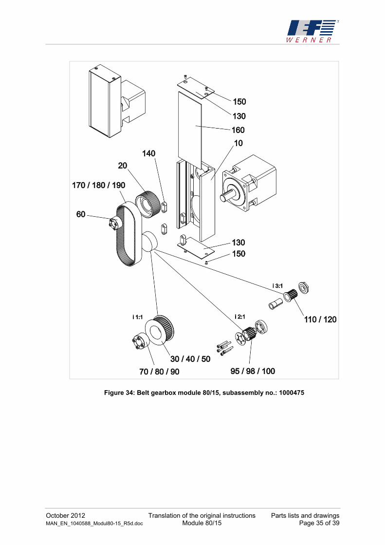
7.4 (Belt) Gearbox module 80/15
Subassembly No.: 1000475; see Figure 34, page 35.
Drawing item
Article no. Part (1) / subassembly (0)
+ Designation
10 1021557 1 + Housing
20 029690 1 Toothed disc AT5/42-0
30 1007376 1 + Toothed disc AT5/42-2
40 028722 1 + Toothed disc AT5/42-2
50 1006664 1 + Toothed disc AT5/42-2
60 732770 1 Clamping set 16/32
70 732770 1 + Clamping set 16/32
80 732294 1 + Clamping set 20/38
90 734168 1 + Clamping set 22/40
95 526735 1 + Toothed disc AT5/20-2, incl. clamping set 12
98 525983 1 + Toothed disc AT5/20-2, incl. clamping set 14
100 525984 1 + Toothed disc AT5/20-2, incl. clamping set 16
110 1005790 1 + Toothed disc AT5/14-2, incl. clamping set 10
120 1005756 1 + Toothed disc AT5/14-2, incl. clamping set 12
130 1003999 1 Belt gearbox lid
140 028574 1 Motion link
150 626072 1 Fillister head screw ISO 7380-M4x8-8.8
160 1004001 1 Insertion cover
170 730353 1 + Toothed belt 25AT5/390
180 732286 1 + Toothed belt 25AT5/375
190 908243 1 + Toothed belt 25AT5/450
+ use depending on design
October 2012 Translation of the original instructions Parts lists and drawings MAN_EN_1040588_Modul80-15_R5d.doc Module 80/15 Page 35 of 39
Figure 34: Belt gearbox module 80/15, subassembly no.: 1000475

Parts lists and drawings Translation of the original instructions October 2012 Page 36 of 39 Module 80/15 MAN_EN_1040588_Modul80-15_R5d.doc
7.5 Flange
Subassembly No.: 1000476; see Figure 35, bottom.
Drawing item
Article no. Part (1) / subassembly (0)
+ Designation
10 1022105 1 Flange axial
20 1022129 1 Flange plate axial
30 734161 1 Plastic cover
40 626037 1 Cylindrical screw DIN 912 - M6x20-8.8
50 626244 1 Cylindrical screw DIN 912-M6x60-8.8
60 627215 1 Retention ring
70 1022199 1 + Coupling Ø=16
75 1022203 1 Ring gear red
80 1022201 1 + Coupling Ø=20
90 1022202 1 + Coupling Ø=22
100 1006530 1 + Sleeve 12/16
110 1007310 1 + Sleeve 15/20
120 1008886 1 + Sleeve 14/16
130 1022206 1 + Sleeve 19/22
+ use depending on design
10
20
30
5060
40
707570 / 80 / 90100 / 110 / 120 / 130
Figure 35: Flange module 80/15; i = 1:1, subassembly no.: 1000476
CAUTION Please additionally observe the wear parts list included with the delivery according to the order.

October 2012 Translation of the original instructions Parts lists and drawings MAN_EN_1040588_Modul80-15_R5d.doc Module 80/15 Page 37 of 39
7.6 Design-specific assemblies/components
7.6.1 Installation flange gearbox (e.g. planetary gear type PLFE64)
The following different drive units for flange gearboxes may be used:
Designation Part No.:
Drive unit 80/15/50/FLG 1059629
Drive unit 80/15/50/FLG/PA 1050222
Figure 36: Installation flange gear (example with drive unit 1059629)
Flange gears
Drive unit

Parts lists and drawings Translation of the original instructions October 2012 Page 38 of 39 Module 80/15 MAN_EN_1040588_Modul80-15_R5d.doc
7.6.2 Overview clamping elements
Clamping element, example type 105 Scaled drawing clamping element
Clamping element
Type: L1 in mm L2 in mm Article number:
16 0 16 220701
65 49 65 1062169
80 64 80 1021641
105 89 105 28674
115 99 115 1054491
140 124 140 220702
160 64 160 1039032
undrilled customer-specific 1019192
Typ 16
Typ 80
Typ 65
Typ 105
Typ 140
Typ 115
Typ 160
Spannprofil L = k undenspezifisch
L
8
8
8
88
8
88
8
88
8
8
L1 L1
L1
L1
L1
L1
L1
L2 L2 L2
L2
L2
L28
8
L2
88
8
8
8
Figure 37: Overview clamping elements
Countersink DIN74 Km 6 (2x)
Clamping profile L = customer-specific

October 2012 Translation of the original instructions Declaration of incorporation MAN_EN_1040588_Modul80-15_R5d.doc Module 80/15 Page 39 of 39
8 Declaration of incorporation
EC declaration of incorporation in the sense of the EC directive 2006/42/EC (machinery), Annex II B
The manufacturer:
IEF Werner GmbH
Wendelhofstraße 6
78120 Furtwangen - Germany
hereby declares that the following products (the incomplete machine/partial machine):
Designation IEF Werner parts group number
Module 80/15 TG1000398
where possible based on the scope of delivery, correspond to the following basic requirements of the directive on Machinery (2006/42/EC):
Annex I, item: 1.1.2; 1.1.3; 1.1.5; 1.3.2; 1.3.4; 1.5.1; 1.7.3.
The incomplete machine also corresponds to the following further directives:
Directive 2004/108/EC of the council, dated 15 December 2004, for harmonisation of the legal provisions of the member states on electromagnetic compatibility.
Directive 2006/95/EC of the council, dated 12 December 2006, for harmonisation of the legislation of the member states regarding electrical equipment for use within specified voltage thresholds.
The technical documents were generated according to Annex VII part B and may be electronically submitted to the national authorities upon justified request.
List of some applied harmonised standards: EN ISO 12100-1,-2 / EN ISO 13857 / EN ISO 13850 / EN 60201-1
Commissioning of the incomplete machine delivered by us is not permitted until it has been determined that the overall system into which the incomplete machine is installed meets the basic safety and health protection requirements according to Annex I of the above EC directive 2006/42/EC.
Name of the documentation officer: Frank Reichelt, technical editor
Address of the documentation officer: see manufacturer's address
Furtwangen, 07.02.10 Manfred Bär (manager)