transit sealant evaluation final brief - nsrp
TRANSCRIPT

Approved for public release; distribution is unlimited. NATIONAL SHIPBUILDING RESEARCH PROGRAM
Electric Technologies Panel Meeting Washington DC
Transit Sealant Evaluation Project
Presented by: Gregory D. StevensGeneral Dynamics, Bath Iron WorksJuly 24th, 2013
NATIONAL SHIPBUILDING RESEARCH PROGRAM2
SEE TITLE PAGE FOR DISTRIBUTION CONTROL
Project Mission and Premise
Although robust and traditionally a strong cable penetration support system, transits using block systems are time consuming and expensive
Looking for affordable alternatives that offer similar benefits
Watertightness
Shock, vibration and fire resistance
Low toxicity
While also offering
Affordability
Minimal installation time and components
More flexible to change after cable routing is complete
Straight forward cable replacement and additions

NATIONAL SHIPBUILDING RESEARCH PROGRAM3
SEE TITLE PAGE FOR DISTRIBUTION CONTROL
Project Participants
BIW – Lead
Bollinger Shipyards
Huntington Ingalls Inc., Newport News
WO Supply
Beele Engineering
Emerson Industrial Automation
Sealand Pipe
Raytheon
AeroNav Laboratories
NATIONAL SHIPBUILDING RESEARCH PROGRAM4
SEE TITLE PAGE FOR DISTRIBUTION CONTROL
Transit Sealant Evaluation Project Goals
Research Available Products
Evaluate Requirements
Generate Evaluation Guide
Evaluate Product Information
Develop Test Procedure
Manufacture Demonstrator
Conduct Testing
Evaluate Results
Generate Report and Recommendations

NATIONAL SHIPBUILDING RESEARCH PROGRAM5
SEE TITLE PAGE FOR DISTRIBUTION CONTROL
Research Available Products
Several products were investigated
A down select was conducted based on data
Three products were tested
One product currently used on programs is considered a baseline

NATIONAL SHIPBUILDING RESEARCH PROGRAM6
SEE TITLE PAGE FOR DISTRIBUTION CONTROL
Evaluate Requirements
Several standards and Mil-Specs were reviewed, and notes made
Item Reference Section Section Language Remarks1 MIL-STD-2003-3A DEPARTMENT OF
DEFENSESTANDARD PRACTICEELECTRIC PLANT INSTALLATIONSTANDARD METHODS FORSURFACE SHIPS AND SUBMARINES(Penetrations)
4.1.5 4.1.5 Multiple (two or more) penetrations of nonstructural steel bulkheads (otherthan wire mesh or expanded metal), bends, web frames, transverse girders, andlongitudinal girders. Unless otherwise specified, multiple cable metal), bends, webframes, transverse girders, and longitudinal girders. Unless otherwise specified,multiple cable penetrations of nonstructural steel bulkheads, bents, web frames,transverse girders, and longitudinal girders shall employ one of the following:a. Metal stuffing tubes, multiple cable penetrators, nipples (for single cablepenetrations) having a minimum length of two inches with a minimum annular areabetween the cable and the nipple of ¼ inch packed with plastic sealerb. Banding collars (for multiple cable penetrations) having a minimum collar lengthof three inches with a minimum annular area between the cable and the collar ofone inch with the entire void area within the collar (this includes the area betweenthe collar and the cable and the area between the cables) packed with plasticsealer. Cable penetrations of vertical non-tight structures within a compartment need
Talks about using a plastic sealer in various applications throughout this and similar sections
4.1.6 4.1.6 Plastic sealer. After the cables are properly secured, plastic sealer electricalinsulation (MIL-I-3064, Type HF) shall be used to seal the space around the cableas follows:a. In cable clamps and bushings entering the top of an electrical enclosure and theside of an enclosure without a drip loop.b. In bushings or nipples used for passing cables through light-tight and fume-tightbulkheads and to seal around cables as they enter stuffing tubes, kickpipes, andswage tubes as shown on the individual figures except that plastic sealer is notrequired when silicone (red or white) grommets are used. Where compartment airtests are required, it is recommended that plastic sealer be installed after the airtest has been satisfactorily performed.
FIGURE 3B51. Community cable tube – watertight decks (poured seal
Shows the use of sealants and multicable transit applications.
FIGURE 3B22. Multiple cable penetrator installation notes (type RGS and RGA).
This figure and next talk to using blocks, but may be applicable with sealant materials
FIGURE 3B39. Round multi-cable penetrators installation notes
2 MIL-STD-2003-4A DEPARTMENT OF DEFENSESTANDARD PRACTICEELECTRIC PLANT INSTALLATIONSTANDARD METHODS FORSURFACE SHIPS AND SUBMARINES(CABLEWAYS)
4.2 Spare cable space allowance
4.2 Spare cable space allowance. In the organization of principal cableways, sparecable space of approximately 20 percent of that to be occupied by the final cableinstallation (as known at time of delivery of the ship) shall be reserved on cablewaysand in cable penetration areas for future cable installations. The additional cablespace may consist of unused hangers or combination of unused hangers andspace available on used hangers, assuming that for future addition of cable, doublebanking will be allowed. During the design phase, the contractor shall providecableway space in excess of the spare 20 percent in order to accommodate cablesadded as a result of developments occurring during the construction period.Through horizontal cable runs in aircraft carriers’ hanger developments occurringduring the construction period. Through horizontal cable runs in aircraft carriers’hanger developments occurring during the construction period. Through horizontalcable runs in aircraft carriers’ hanger spaces will not be permitted. Through verticalruns such as those from the second deck to the gallery or flight decklevels shall be g
References for Transit Component Usage
Compilation for future reference supporting possible requirements revision

NATIONAL SHIPBUILDING RESEARCH PROGRAM7
SEE TITLE PAGE FOR DISTRIBUTION CONTROL
Generate Evaluation Guide
A means to consistently compare products was needed
Team developed a simple guide to help compare product characteristics across evaluation group, and compare to requirements
The following are criteria that will be used to evaluate the performance of the tested transit sealant products. Some criteria are based on established standards and requirements, which are referenced for convenience.
Product: Tested by: Date: Submitted by:
Item Description Min/Max Requirement UOM Value
Meets Requirement?
(Y/N)Testing Date Comments/Remarks
1 Cure Time hrs2 Operating Temperature - nominal F3 Max. Operating Temperature F4 Flame Resistance F/hr or C/hr5 Water/Air Pressure Withstand psi6 Packaging Size in3
7 Packaging n/a how is the product packaged?8 Delivery n/a how is the product applied (caulking gun, knife, etc.)
Evaluation Criteria

NATIONAL SHIPBUILDING RESEARCH PROGRAM8
SEE TITLE PAGE FOR DISTRIBUTION CONTROL
Evaluate Product Information
The previous evaluation guide templates were filled in with vendor data
This enables a consistent comparison across samples and attributes
Allows for a down select to build unit demonstrators with sample materials

NATIONAL SHIPBUILDING RESEARCH PROGRAM9
SEE TITLE PAGE FOR DISTRIBUTION CONTROL
Develop Test Procedure
To test the samples, a test procedure was developed
Primary tests include:
Vibration
Shock
Watertightness
Fire resistance
Independent lab was contracted to conduct testing
NATIONAL SHIPBUILDING RESEARCH PROGRAM10
SEE TITLE PAGE FOR DISTRIBUTION CONTROL
Manufacture Demonstrator
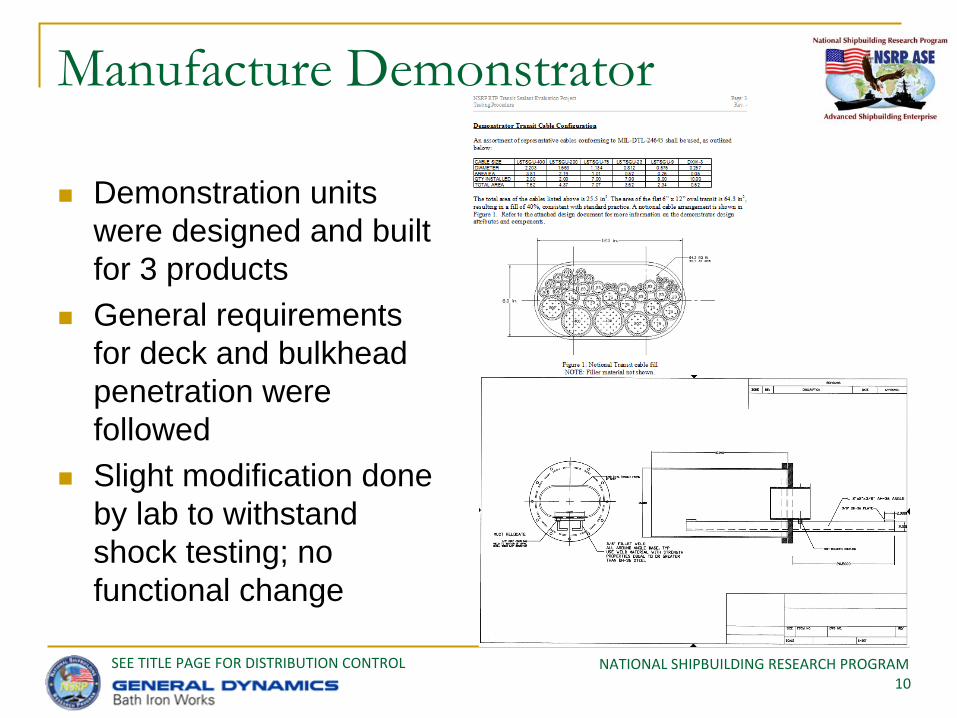
Demonstration units were designed and built for 3 products
General requirements for deck and bulkhead penetration were followed
Slight modification done by lab to withstand shock testing; no functional change
NATIONAL SHIPBUILDING RESEARCH PROGRAM11
SEE TITLE PAGE FOR DISTRIBUTION CONTROL
Manufacture Demonstrator (cont.)
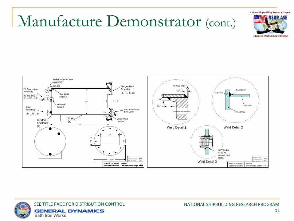
Relief Valve/Air Vent Assembly
(7), (8)Fill Connection Assembly
(8), (9), (10), (11), (12), (14)
Drain Assembly
(8), (13), (15)
Flanged Head Assembly
(3), (4), (5), (6)
Shell (1)Welded
End Plate (2)
See Weld Detail 2
See Weld Detail 3
See Weld Detail 1
12”
6”
8”
12”
24”
24”
24”
24”
6”6”6”
Inner penetrator drain valve
24”
NSRP ETP Transit Sealant Evaluation
Sealant Demonstrator Design
Bath Iron Works
700 Washington St.
Bath, ME 04534
SH 1
5/4/12
Rev. -
SH 1
5/4/12
Rev. -
SH 1
24”16.25”
NSRP ETP Transit Sealant Evaluation
Sealant Demonstrator Design SH 1
5/4/12
Rev. -
SH 1
5/4/12
Rev. -
SH 1
6”
14”
Pipe Shell
Head Plate
1/2” MinBevel @ 45°
Weld Detail 2Weld Detail 1
¼” Gap Max
¼”
¼”
¼”
Weld Detail 3
1/8” Double Fillet, All around, both sides.
NSRP ETP Transit Sealant Evaluation
Sealant Demonstrator Design
5/4/12
Rev. -
5/4/12
Rev. -
SH 2
Bath Iron Works
700 Washington St.
Bath, ME 04534

NATIONAL SHIPBUILDING RESEARCH PROGRAM12
SEE TITLE PAGE FOR DISTRIBUTION CONTROL
Conduct Testing
Hydro testing completed at BIW; repairs made
Shock, vibration and various hydrostatic tests were conducted by the lab
One product marginally failed the hydro testing after the shock testing
Repairs were made and testing completed

NATIONAL SHIPBUILDING RESEARCH PROGRAM13
SEE TITLE PAGE FOR DISTRIBUTION CONTROL
Nelson Firestop
(BIW Testing)8
Pressure at 4.5 #

NATIONAL SHIPBUILDING RESEARCH PROGRAM14
SEE TITLE PAGE FOR DISTRIBUTION CONTROL
Nelson Firestop
(BIW Testing)11
At 12 psi
Water leaking on the larger cables

NATIONAL SHIPBUILDING RESEARCH PROGRAM15
SEE TITLE PAGE FOR DISTRIBUTION CONTROL
FIRESTOP 3000 with D-24 BLANKET (BIW Testing)
20
¾” dia hole through the inside seal
NATIONAL SHIPBUILDING RESEARCH PROGRAM16
SEE TITLE PAGE FOR DISTRIBUTION CONTROL
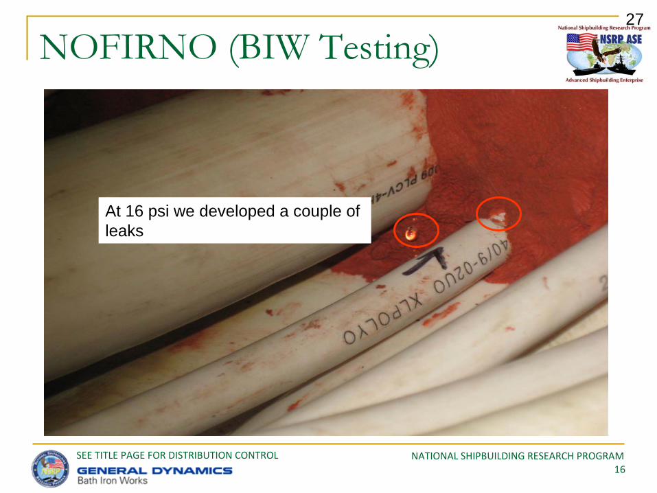
NOFIRNO (BIW Testing)27
At 16 psi we developed a couple of leaks
NATIONAL SHIPBUILDING RESEARCH PROGRAM17
SEE TITLE PAGE FOR DISTRIBUTION CONTROL
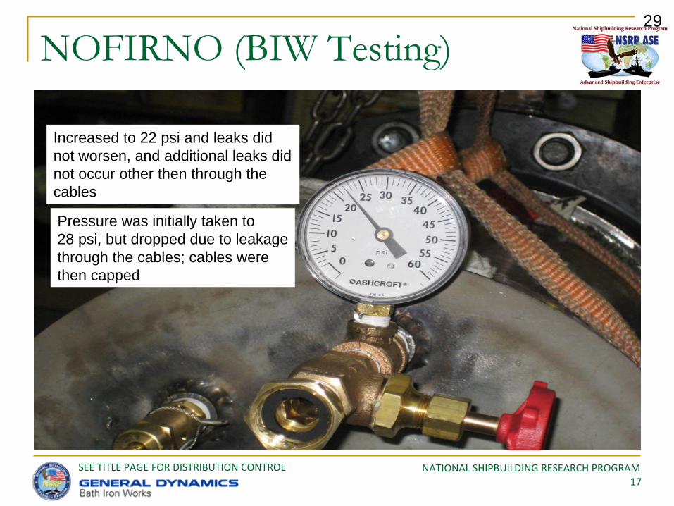
NOFIRNO (BIW Testing)29
Increased to 22 psi and leaks did not worsen, and additional leaks did not occur other then through the cables
Pressure was initially taken to 28 psi, but dropped due to leakagethrough the cables; cables were then capped
NATIONAL SHIPBUILDING RESEARCH PROGRAM18
SEE TITLE PAGE FOR DISTRIBUTION CONTROL
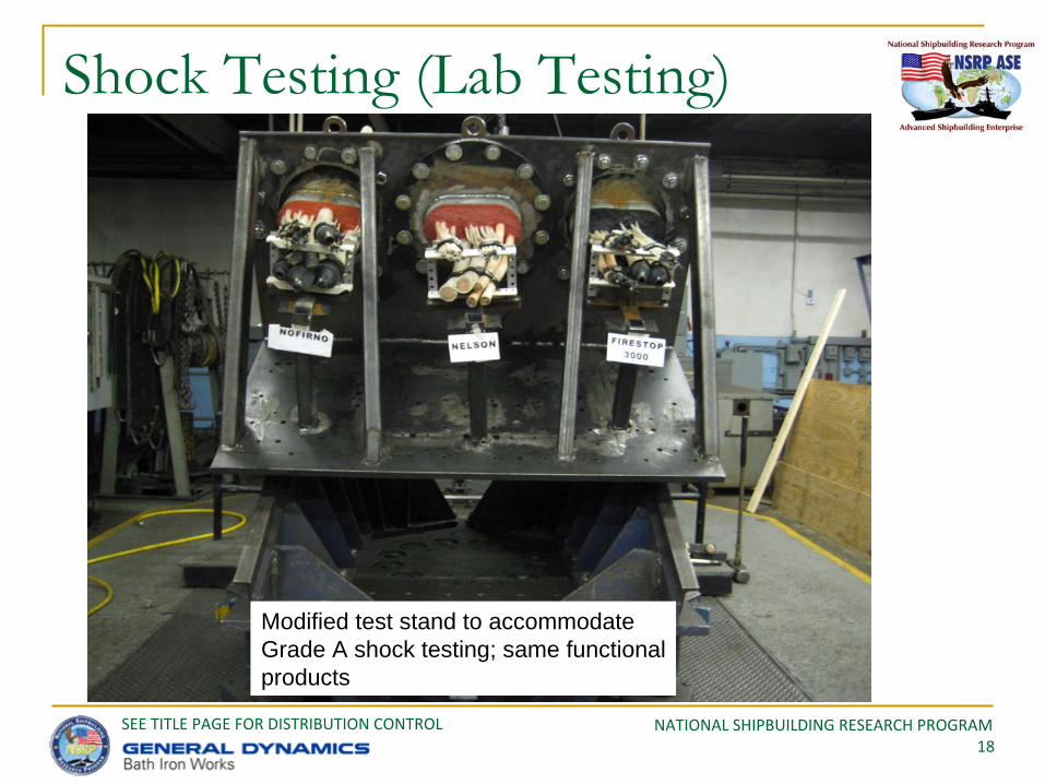
Shock Testing (Lab Testing)
Modified test stand to accommodateGrade A shock testing; same functionalproducts
NATIONAL SHIPBUILDING RESEARCH PROGRAM19
SEE TITLE PAGE FOR DISTRIBUTION CONTROL
Results
All units considered to have passed all tests, except for the hydrostatic test after the shock testing (NOFIRNO); repairs made and testing commenced
Upon close inspection, after fire testing, all products appear to have good mechanical strength and withstand
Cure time really made a difference when it was time to shock and fire test products
Holes easily cut into material to install other cables, and easily repaired

NATIONAL SHIPBUILDING RESEARCH PROGRAM20
SEE TITLE PAGE FOR DISTRIBUTION CONTROL
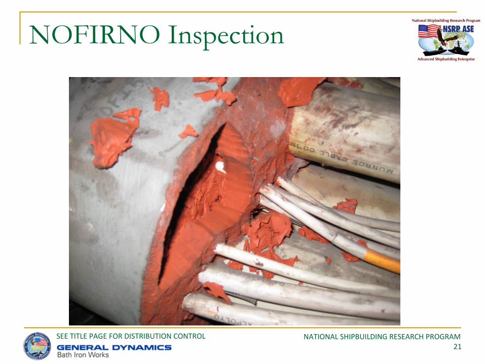
NOFIRNO Inspection
Heat effects on cable jacketsSome gaps
observed
Separation line
Heat effects on cable jackets
NATIONAL SHIPBUILDING RESEARCH PROGRAM21
SEE TITLE PAGE FOR DISTRIBUTION CONTROL
NOFIRNO Inspection

NATIONAL SHIPBUILDING RESEARCH PROGRAM22
SEE TITLE PAGE FOR DISTRIBUTION CONTROL
NOFIRNO Post Fire Test

NATIONAL SHIPBUILDING RESEARCH PROGRAM23
SEE TITLE PAGE FOR DISTRIBUTION CONTROL
NOFIRNO Inspection (fire side)
Tubes and sheathsTubes and sheaths Filler expanded

NATIONAL SHIPBUILDING RESEARCH PROGRAM24
SEE TITLE PAGE FOR DISTRIBUTION CONTROL
Fire Seal Inspection

NATIONAL SHIPBUILDING RESEARCH PROGRAM25
SEE TITLE PAGE FOR DISTRIBUTION CONTROL
Fire Seal Inspection
NATIONAL SHIPBUILDING RESEARCH PROGRAM26
SEE TITLE PAGE FOR DISTRIBUTION CONTROL
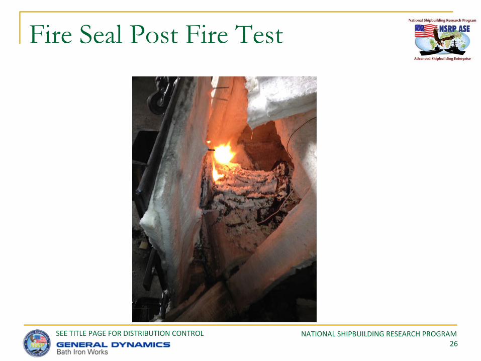
Fire Seal Post Fire Test

NATIONAL SHIPBUILDING RESEARCH PROGRAM27
SEE TITLE PAGE FOR DISTRIBUTION CONTROL
Fire Seal Inspection (fire side)
Blanket component
NATIONAL SHIPBUILDING RESEARCH PROGRAM28
SEE TITLE PAGE FOR DISTRIBUTION CONTROL
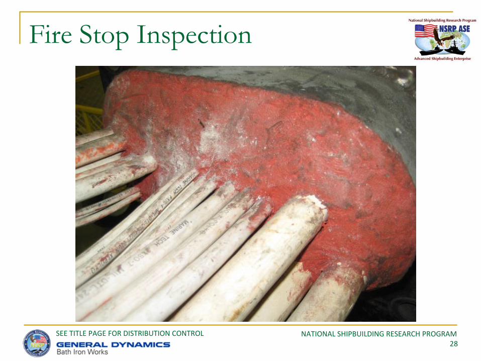
Fire Stop Inspection
NATIONAL SHIPBUILDING RESEARCH PROGRAM29
SEE TITLE PAGE FOR DISTRIBUTION CONTROL
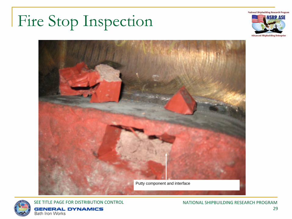
Fire Stop Inspection
Putty component and interface
NATIONAL SHIPBUILDING RESEARCH PROGRAM30
SEE TITLE PAGE FOR DISTRIBUTION CONTROL
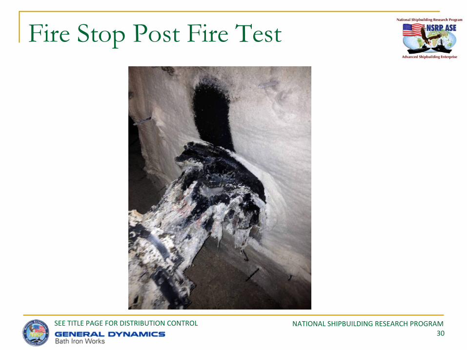
Fire Stop Post Fire Test

NATIONAL SHIPBUILDING RESEARCH PROGRAM31
SEE TITLE PAGE FOR DISTRIBUTION CONTROL
Fire Stop Inspection (fire side)

NATIONAL SHIPBUILDING RESEARCH PROGRAM32
SEE TITLE PAGE FOR DISTRIBUTION CONTROL
Quantitative Assessment: Cost Benefit Evaluation
Input Data Set
Failure Rate
Materials Labor Materials Labor Materials Labor Materials Labor
Averages: All $380 3 ($8) 1 20% 1,413 2,817 $805,482 6,326 ($28,228) 565
Averages: Closest $250 1 $8 1 20% 2,108 4,216 $527,003 4,216 ($42,160) 843
$484,842 5,059
Notes: 1. Failure rate is defined as not meeting a requirement, such as testing (testing is the basic vehicle referenced here to make that determination)2. Values are approximations reflecting program experience, experimentation, etc.3. Programs represents a per unit transit of 2" X 6"4. Installation includes everything from the time the arrangement drawing is addressed to completion (planning cable routing, does not include testing)5. The scale is applied to account for the difference with respect to the baseline size of 2" X 6", and the number of this scaled version as a percentage of overall on the ship6. The above represents a very rough order of magnitude to determine just how much opportunity exists to using one technology over another.7. Materials are in dollars, labor in hours.8. Vendor estimates for cost differences is applied to the average scaled values9. The closest program information is averaged to form one set of data10. This data assumes the performance characteristics between the two methods is the same11. It is assumed the soft sealant systems are given adequate time to cure12. It is assumed the environmental conditions during installation and cure time are compatible with cure time requirements
Total Cost Savings Using Sealant Systems Over Transit Systems (using 2 closest averages)
NSRP Transit Sealant Project: General Cost Savings Data
Estimated Cost Difference (pu measures for Transit Systems minus Soft Sealant Systems)
Approx. Number per Ship - Scaled
for Materials
Approx. Number per Ship - Scaled
for Labor
Estimated Cost Difference (calculated measures for Transit Systems minus Soft Sealant Systems)
Initial Installation Repair Initial Installation Repair
NATIONAL SHIPBUILDING RESEARCH PROGRAM33
SEE TITLE PAGE FOR DISTRIBUTION CONTROL
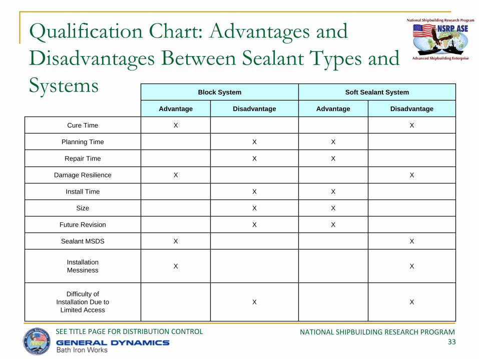
Qualification Chart: Advantages and Disadvantages Between Sealant Types and Systems Block System Soft Sealant System
Advantage Disadvantage Advantage Disadvantage
Cure Time X X
Planning Time X X
Repair Time X X
Damage Resilience X X
Install Time X X
Size X X
Future Revision X X
Sealant MSDS X X
Installation Messiness X X
Difficulty ofInstallation Due to
Limited AccessX X
NATIONAL SHIPBUILDING RESEARCH PROGRAM34
SEE TITLE PAGE FOR DISTRIBUTION CONTROL
Conclusions
Sealant materials are a bit messy to use
All inner components worked pretty well once totally cured, including fire matting material
Long cure times may affect space preparation planning
Pretty easy to cut and install another cable once cured
Very impressive fire test results for all sealants
These sealants are quite resilient and strong; could be used below the waterline/v-line

NATIONAL SHIPBUILDING RESEARCH PROGRAM35
SEE TITLE PAGE FOR DISTRIBUTION CONTROL
Recommendations for Future Work
Cost Data Estimates
Confirm sealant system qualification testing costs
Confirm ROI for sealants for a particular ship program
Numbers presented are considered ROMs
Qualification Program
Sealant manufacturers should generate qualification programs and approach the NTWHs
Universal Requirements
Requirements should be expanded, universal and allow for larger number of configurations
This will be driven in part on results of qualification testing
NATIONAL SHIPBUILDING RESEARCH PROGRAM36
SEE TITLE PAGE FOR DISTRIBUTION CONTROL
Recommendations for Future Work (cont.)
Product Effectiveness
Through testing cycles and life cycle assessment, determine the effectiveness of products over the application life cycle
Should be data in the commercial sector to do this
Vendors should expand product capability
Quick cure components
Low smoke, low toxicity improvements
Maintain strength and flexibility

NATIONAL SHIPBUILDING RESEARCH PROGRAM37
SEE TITLE PAGE FOR DISTRIBUTION CONTROL
Questions??
Thank you for your support and participation