transient thermal analysis of engine exhaust valve
DESCRIPTION
Valve FailureTRANSCRIPT
This article was downloaded by: [INASP - Pakistan (PERI)]On: 25 May 2015, At: 02:46Publisher: Taylor & FrancisInforma Ltd Registered in England and Wales Registered Number: 1072954 Registeredoffice: Mortimer House, 37-41 Mortimer Street, London W1T 3JH, UK
Numerical Heat Transfer, Part A:Applications: An International Journal ofComputation and MethodologyPublication details, including instructions for authors andsubscription information:http://www.tandfonline.com/loi/unht20
Transient Thermal Analysis of EngineExhaust ValveM. H. Shojaefard a , A. R. Noorpoor a , D. A. Bozchaloe a & M.Ghaffarpour ba Automotive Engineering Department , Iran University of Scienceand Technology , Tehran, Iranb UIC Combustion and Engine Laboratory, Department of MechanicalEngineering , University of Illinois at Chicago , Chicago, Illinois, USAPublished online: 24 Feb 2007.
To cite this article: M. H. Shojaefard , A. R. Noorpoor , D. A. Bozchaloe & M. Ghaffarpour(2005) Transient Thermal Analysis of Engine Exhaust Valve, Numerical Heat Transfer, Part A:Applications: An International Journal of Computation and Methodology, 48:7, 627-644, DOI:10.1080/10407780590959943
To link to this article: http://dx.doi.org/10.1080/10407780590959943
PLEASE SCROLL DOWN FOR ARTICLE
Taylor & Francis makes every effort to ensure the accuracy of all the information (the“Content”) contained in the publications on our platform. However, Taylor & Francis,our agents, and our licensors make no representations or warranties whatsoever as tothe accuracy, completeness, or suitability for any purpose of the Content. Any opinionsand views expressed in this publication are the opinions and views of the authors,and are not the views of or endorsed by Taylor & Francis. The accuracy of the Contentshould not be relied upon and should be independently verified with primary sourcesof information. Taylor and Francis shall not be liable for any losses, actions, claims,proceedings, demands, costs, expenses, damages, and other liabilities whatsoever orhowsoever caused arising directly or indirectly in connection with, in relation to or arisingout of the use of the Content.
This article may be used for research, teaching, and private study purposes. Anysubstantial or systematic reproduction, redistribution, reselling, loan, sub-licensing,systematic supply, or distribution in any form to anyone is expressly forbidden. Terms &

Conditions of access and use can be found at http://www.tandfonline.com/page/terms-and-conditions
Dow
nloa
ded
by [
INA
SP -
Pak
ista
n (P
ER
I)]
at 0
2:46
25
May
201
5
TRANSIENT THERMAL ANALYSIS OF ENGINEEXHAUST VALVE
M. H. Shojaefard, A. R. Noorpoor, and D. A. BozchaloeAutomotive Engineering Department, Iran University of Science andTechnology, Tehran, Iran
M. GhaffarpourUIC Combustion and Engine Laboratory, Department of MechanicalEngineering, University of Illinois at Chicago, Chicago, Illinois, USA
Internal combustion engines produce exhaust gases at extremely high temperatures and
pressures. As these hot gases pass through the exhaust valve, temperatures of the valve,
valve seat, and stem increase. To avoid any damage to the exhaust valve assembly, heat
is transferred from the exhaust valve through different parts, especially the valve seat insert
during the opening and closing cycle as they come into contact with each other. In this arti-
cle, a finite-element method is used for modeling the transient thermal analysis of an
exhaust valve. The temperature distribution and resultant thermal stresses at each opening
and closing time are obtained. Detailed analyses are performed to estimate the boundary
conditions of an internal combustion engine. The model includes exhaust valve, seat, guide,
and spring. The analysis continues until a steady-state condition is obtained. In this study,
ANSYS is employed for modeling and analysis of the exhaust valve. A methodology is
developed for transient thermal analysis of the exhaust valve.
1. INTRODUCTION
Because of exposure to hot exhaust gases and its effects on engine performanceand volumetric efficiency, the exhaust valve of an internal combustion engine is oneof the most critical parts. The design of exhaust valves depends on many parameters,such as fluid dynamics of the exhaust gas, fatigue strength of the valve material, oxi-dation characteristics of the valve material, exhaust gas behavior of the material athigh temperature, the configuration of the cylinder head, the coolant flow, the shapeof the exhaust port, etc. [1–3].
The most significant factor in the performance of an exhaust valve is its oper-ating temperature. The importance of temperature can best be appreciated byits effect on the physical properties of the valve steel. The exhaust valve of an internalcombustion engine operates under severe conditions of thermal, fatigue, and mech-anical stresses [4]. Large temperature gradients in the valve body are responsible
Received 8 April 2004; accepted 4 March 2005.
Address correspondence to M. Ghaffarpour, Department of Mechanical Engineering, University of
Illinois at Chicago, 842 Taylor Street, 2039 ERF (MC 251), Chicago, IL 60607, USA. E-mail: mghaffar@
uic.edu
627
Numerical Heat Transfer, Part A, 48: 627–644, 2005
Copyright # Taylor & Francis Inc.
ISSN: 1040-7782 print=1521-0634 online
DOI: 10.1080/10407780590959943
Dow
nloa
ded
by [
INA
SP -
Pak
ista
n (P
ER
I)]
at 0
2:46
25
May
201
5

for thermal stresses. Knowledge of the temperature field in different parts of aninternal combustion engine is important in order to ascertain the points of highestthermal stress [5]. A designer is always interested in obtaining an optimum conditionso that the engine parts are not subjected to excessive stresses due to gas pressure(mechanical loading) and thermal loading [6, 7]. Meanwhile, the engine should notlose a large amount of heat through the parts [8].
To obtain an optimum condition and accurate estimations of heat flow rates,the temperature distribution and resulting thermal stresses in internal combustionengine parts such as piston, valves, the cylinder head, and cylinder walls are needed[9]. Thermal analysis guides us to design and optimize the engine parts to estimateheat flow accurately, lowers the temperature, and consequently prevents failure ofthe parts due to excessive stresses, fatigue, corrosion, etc. [10, 11]. Modern enginethermal management systems regulate the thermal processes through coolant and=orair flow rates, fuel injection, ignition timing, and exhaust gas recirculation. One of theprimary functions of the engine control unit is the prevention and detection of abnor-mal combustion in order to prevent severe engine damage. The solutions for theproblems are challenging and complicated due to the following reasons [12–14].
1. The temperature of gases inside the engine cylinder varies cyclically.2. Parts such as valves have no regular cylindrical shape and are subjected to differ-
ent temperatures, and heat transfer coefficients from the top, bottom, and sides.3. It is extremely difficult to estimate the exact values of the temperature distri-
bution and heat transfer coefficient.
Exhaust valve temperature measurements have been made by a numberof investigators [15–18]. They measured the surface temperature of the valve by athermocouple at several different locations [19]. In early 1990, a major thermal
NOMENCLATURE
b piston bore, m
C specific heat, J=kg �CD valve stem diameter, m
E Young’s modulus, GPa
he exhaust gas heat transfer coefficient,
W=m2 �ChgðhÞ heat transfer coefficient, W=m2 �Chgm mean heat transfer coefficient, W=m2 �Chp engine horse power, hp
i number of cycles
Ke exhaust valve thermal conductivity
coefficient, W=m �CK thermal conductive coefficient, W=m �CM rotation speed of camshaft, rpm
pgðhÞ gas pressure [KPa]
RPM engine speed, rpm
Su ultimate strength, MPa
Sy yield strength, MPa
t1 closing time of the valve, s
t2 opening time of the valve, s
T temperature of material, �CTc temperature of the contact elements, �CTCC thermal contact coefficient, W=m2 �CTe exhaust gas temperature, �CTgðhÞ gas temperature, �CTgr resulting gas temperature, �CTt temperature of the target elements, �CVe exhaust gas speed, m=s
Vp mean piston speed, m=s
a thermal expansion coefficient, 10�6=�Ch crank shaft angle, deg
q density, kg=m3
qe exhaust gas density, kg=m3
m exhaust gas viscosity, kg=ms
n Poisson ratio
628 M. H. SHOJAEFARD ET AL.
Dow
nloa
ded
by [
INA
SP -
Pak
ista
n (P
ER
I)]
at 0
2:46
25
May
201
5
and resulting stress analysis of the valves was achieved [20]. These authors calculatedthe temperature distribution and thermal stress distribution in a valve by using thefinite-difference method. However, the effects of valve motion were not considered.The authors assumed that the valves are in constant contact with the seat. Recently,the finite element analysis (FEA) code plays an important role in thermal stressanalysis [21].
In situ, the temperature fields were measured under periodic contact for anactual valve seat configuration [22]. A variety of researchers have proposed dynamicmodels to derive and validate a lumped-capacity engine block and head model tostudy temperature, heat flow, and friction characteristics [23]. Others presented acomprehensive resistor-capacitor model to describe the engine exhaust system, aswell as physically estimate the thermal resistances [24]. Air-to-fuel ratio is one ofthe most important parameters affecting engine performance and maximum gas tem-perature. Consequently, it changes the exhaust valve temperature, which reaches itsmaximum near stoichiometric air–fuel ratio [25]. The contact resistance betweenthe valve and seat was modeled for constant steady-state conditions by other resear-chers. They state that, for steady-state and closed valve conditions, approximately76% of the heat in the valve stem transfers through the valve seat, whereas theremaining 24% travels through the valve stem [26, 27].
More recently, researchers [28] have demonstrated a nonlinear dynamic ther-mal model to describe the transient and steady-state phenomena in an engine’s cyl-inder using a lumped-parameter resistance-capacitance network. The model was ableto predict an engine’s thermal behavior as the exhaust valve contacts its seat. Otherinvestigators [29] applied the conjugate gradient method with two search step sizes tosolve the inverse problem of simultaneously estimating the periodic thermal contactconductance, h(c)(t), and the heat transfer coefficient of the exhaust gases, h(g)(t),between the exhaust valve and seat in an internal combustion engine. The resultsshowed that the CPU time for the inverse solutions using two search step sizes isgreatly reduced as opposed to using just one search step size for the determinationof two unknowns. In addition, it was also shown that the inverse solutions are reliableeven when the measurement errors are considered. The development of the presenttechnique can be applied to any kind of two-dimensional periodic contact problem,such as the determination of a two-dimensional contact conductance problem andthe temperature or heat flux behavior inside the wall of internal combustion engines.
The ultimate objective of engine thermal management is to achieve satisfactorytrade-offs between power, emissions, and efficiency for various engine speeds andloads. Therefore, prediction of the temperature distribution, heat flow rates, andresulting thermal stresses in the exhaust valve at maximum engine load is of primeinterest to achieve the goal. In this study, the finite-element package ANSYS is used.The motion of the valve is considered for complete analysis.
2. DESCRIPTION OF THE PHYSICAL SYSTEM
The geometry of the exhaust valve is shown in Figure 1. The exhaust valve sits onthe cylinder head of a combustion chamber. The engine coolant liquid passes aroundthe cylinder liner and the water passages in the cylinder head. The valve pops up anddown to let the exhaust gases leave the combustion chamber. The up-and-down
THERMAL ANALYSIS OF ENGINE EXHAUST VALVE 629
Dow
nloa
ded
by [
INA
SP -
Pak
ista
n (P
ER
I)]
at 0
2:46
25
May
201
5

motion of the valve takes place with the help of a rocker lever which is connected to thepush rod. The push rod rests over cams on the camshaft. The valve is spring loaded.The spring keeps the valve connected to the camshaft during its motion.
After the expansion process, the exhaust gases, at high temperature, are purgedthrough the exhaust valve and as a result the temperature of the exhaust valveincreases. In order to avoid any damage to the exhaust valve due to this high tem-perature, heat must be continuously taken away from the valve. This is achievedwhen the valve is in contact with its seat. As the exhaust valves touch its seat, asignificant drop in exhaust valve temperature occurs.
3. NUMERICAL APPROACH AND PROCEDURE
The ANSYS numerical code, Version 6.1, is employed for all numericalpredictions.
3.1. Assignment of the Boundary Conditions
When the valve is in contact with the seat, the valve head is subjected to hotgases, with gas temperature Tg(h) and heat transfer coefficient hg(h). (h) is the crank
Figure 1. Geometry of the exhaust valve.
630 M. H. SHOJAEFARD ET AL.
Dow
nloa
ded
by [
INA
SP -
Pak
ista
n (P
ER
I)]
at 0
2:46
25
May
201
5

shaft angle. hg(h) is calculated using the following equation [6]:
hgðhÞ ¼ 3:26½pgðhÞ�0:8ð6:18� VpÞ0:8b�0:2½TgðhÞ��0:55 ð1Þ
where pgðhÞ is the gas pressure as shown in Figure 3; Vp is the mean piston speed,that is, 10.4m=s; b is the piston bore, that is, 87.3mm; and TgðhÞ is the temperatureas shown in Figure 2.
Because of high variation of the temperature and pressure (Figures 2 and 3) inan engine cycle, the resulting gas temperature Tgr and mean heat transfer coefficient
Figure 3. Diagram of measured gas pressure in the cylinder.
Figure 2. Diagram of measured gas temperature in the cylinder.
THERMAL ANALYSIS OF ENGINE EXHAUST VALVE 631
Dow
nloa
ded
by [
INA
SP -
Pak
ista
n (P
ER
I)]
at 0
2:46
25
May
201
5
hgm can be calculated as [4–6]
Tgr ¼ðhgTgÞmhgm
ð2Þ
hgm ¼ 1
720
Z 720
0
hgðhÞ dh ð3Þ
ðhgTgÞm ¼ 1
720
Z 720
0
hgðhÞTgðhÞ dh ð4Þ
By using Eqs. (1)–(4) and values of the temperature and pressure indicated inFigures 2 and 3, the values of Tgr and hgm are calculated as 840�C and 490W=m2 �C,respectively.
The temperatures of the valve seat and valve guide near the cylinder head areassumed to be 300 and 90�C, respectively. The heat transfer contact coefficientsbetween the valve and valve seat are 5,000 and 170W=m2 �C, respectively. Thesevalues are provided by the engine manufacturer using computational and experi-mental results. When the exhaust valve opens, the exhaust gases leave the combus-tion chamber through the exhaust valve. In this case, the necessary boundaryconditions for numerical analysis are the exhaust gas heat transfer coefficient (he)and the exhaust gas temperature (Te). The exhaust gas temperature is estimated at800�C using the engine cylinder temperature of Figure 2 and the experimental resultsfurnished by the engine manufacturer.
The value of he, the exhaust gas heat transfer coefficient, is calculated usingthe following equations and the estimated exhaust gas temperature as explainedpreviously [4–6]:
Nu ¼ heD
Ke¼ 0:18ðReÞ0:62 ð5Þ
Re ¼ qeVeD
mð6Þ
where D is the valve stem diameter, Ke is thermal conductivity coefficient of theexhaust valve, Ve is the exhaust gas speed, qe is the density of the exhaust gas,and m is the viscosity of the exhaust gas. By using Eqs. (5) and (6) and values ofKe, qe and m at 800�C, the value of he is calculated as 340W=m2 �C.
When the valve is in contact with the valve seat, there is natural heat transferfrom the valve stem to the gases (air and the residual exhaust gas) in the exhaustport. The values of the gas temperature and the heat transfer coefficient are esti-mated at 200�C and 12W=m2 �C, respectively [4, 5]. Similarly, there is a natural heattransfer at the top of the valve stem (exposed to enclosed air). The values of thetemperature and heat transfer coefficient at this end are estimated at 30�C and12W=m2 �C, respectively.
632 M. H. SHOJAEFARD ET AL.
Dow
nloa
ded
by [
INA
SP -
Pak
ista
n (P
ER
I)]
at 0
2:46
25
May
201
5

The values of the boundary conditions used for the analysis are summarized inTable 1. The analysis was performed under the worst thermal loading condition of ratedpower. The engine specification and operating condition are summarized in Table 2.
An analysis procedure using finite-element modeling techniques is developed toanalyze of the exhaust valve thermal behavior. The analysis consist of:
1. Construction of a suitable finite-element model2. Selection of material properties
Table 1. Values of the boundary conditions used in the analysis
Boundary condition description
Valve position
Valve is closed Valve is open
Parameter Value Parameter Value
At the valve head face into
the cylinder, heat transfer
coefficient and temperature
hgm (W=m2 �C) 490 hgm (W=m2 �C) 490
Tgr (�C) 840 Tgr (
�C) 840
At the valve stem and valve
head conical and rounded face into
the exhaust port, heat transfer
coefficient and temperature
— — he (W=m2 �C) 340
— — Te (�C) 800
At the valve stem and rounded
valve head face into the exhaust port,
heat transfer coefficient and temperature
— (W=m2 �C) 12 — —
— (�C) 200 — —
At the top of the valve stem which is
exposed to enclosed air, heat transfer
coefficient and temperature
— (W=m2 �C) 12 — (W=m2 �C) 12
— (�C) 30 — (�C) 30
Between the valve and the valve seat,
heat transfer contact coefficients and
temperature of the valve seat
— (W=m2 �C) 5,000 — —
— (�C) 300 — —
Between the valve and the valve guide,
heat transfer contact coefficients and
temperature of the valve guide
— (W=m2 �C) 170 — (W=m2 �C) 170
— (�C) 90 — (�C) 90
Table 2. Engine specifications and operating conditions
Component Value
Piston bore (mm) 87.3
Connecting rod (mm) 130
Cylinder number 4
Int. valve number 4
Exh. valve number 4
Compression ratio 8.6
Valve lift (mm) 9.5
Engine speed (rpm) 4,700
Air fuel ratio 12
Power (hp) 66
Piston stroke (mm) 66.7
Mean piston speed (m=s) 10.4
THERMAL ANALYSIS OF ENGINE EXHAUST VALVE 633
Dow
nloa
ded
by [
INA
SP -
Pak
ista
n (P
ER
I)]
at 0
2:46
25
May
201
5
3. Application of the thermal boundary conditions4. Solution of the thermal finite-element model to obtain the transient temperature
distribution5. Solution of the structural finite-element model to obtain the stresses resulting
from the imposed temperature
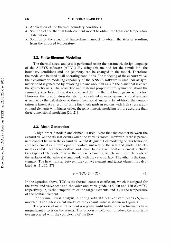
3.2. Finite-Element Modeling
The thermal stress analysis is performed using the parametric design languageof the ANSYS software (APDL). By using this method for the simulation, theboundary conditions and the geometry can be changed in the model. Therefore,the model can be used at all operating conditions. For modeling of the exhaust valve,the axisymmetric modeling capability of the ANSYS software is used. An axisym-metric solid is generated by revolving a plane about an axis in the plane that is calledthe symmetry axis. The geometric and material properties are symmetric about thesymmetry axis. In addition, it is considered that the thermal loadings are symmetric.However, the form of stress distribution calculated in an axisymmetric solid analysisis similar to the calculation of three-dimensional analysis. In addition, the compu-tation is faster. As a result of using fine-mesh grids in regions with high stress gradi-ent and elements with higher order, the axisymmetric modeling is more accurate thanthree-dimensional modeling [20, 21].
3.3. Mesh Generation
A high-order 8-node plane element is used. Note that the contact between theexhaust valve and its seat occurs when the valve is closed. However, there is perma-nent contact between the exhaust valve and its guide. For modeling of this behavior,contact elements are developed in contact surfaces of the seat and guide. The ele-ments exhibit linear temperature and strain fields. Each contact element includestwo types of elements. One is the contact elements, which are those elements atthe surfaces of the valve seat and guide with the valve surface. The other is the targetelement. The heat transfer between the contact element and target element is calcu-lated as [21, 26, 27]
q ¼ TCCðTt � TcÞ ð7Þ
In the equation above, TCC is the thermal contact coefficient, which is assigned forthe valve and valve seat and the valve and valve guide as 5,000 and 170W=m2 �C,respectively. Tt is the temperature of the target elements and Tc is the temperatureof the contact element.
For thermal stress analysis, a spring with stiffness constant 50.33 kN=m ismodeled. The finite-element model of the exhaust valve is shown in Figure 4.
The process of mesh refinement is repeated until further mesh refinements haveinsignificant effects on the results. This process is followed to reduce the uncertain-ties associated with the complexity of the flow.
634 M. H. SHOJAEFARD ET AL.
Dow
nloa
ded
by [
INA
SP -
Pak
ista
n (P
ER
I)]
at 0
2:46
25
May
201
5

3.4. Validation of the Finite-Element Model
The calibration and validation of the computational model is carried out withexperimental data. Data such as dimensions, boundary conditions, and the results of[4, 5] are used. The values of boundary conditions are tabulated in Table 3. Note thatwe used the average values from the mentioned references, although the valve move-ment was not considered in their model. In the model developed, the exhaust valvegeometry is considered as a parameter in the model.
Comparisons between the results at four points are shown in Figure 5. Point 1is at the end of the valve, point 2 at the contact zone of the valve and guide, point 3at the valve stem under the valve guide, and point 4 at the center of the valve head.As Figure 5 shows, the results of the model (solid line) and experimental results(dotted line) match relatively well.
Figure 4. Finite-element model of the exhaust valve.
Table 3. Values of the boundary condition used in [4, 5]
Heat transfer coefficient Value Temperature Value
Gases at the cylinder 300 kcal=m2 h �C Gases at the cylinder 1,000�CExhaust 36 kcal=m2 h �C Exhaust 600�CBetween the valve and the seat 5,000 kcal=m h �C Between the valve and the seat 500�CBetween the valve and the guide 150 kcal=m h �C Between the valve and the guide 90�CEnd of the valve 10 kcal=m h �C End of the valve 30�C
THERMAL ANALYSIS OF ENGINE EXHAUST VALVE 635
Dow
nloa
ded
by [
INA
SP -
Pak
ista
n (P
ER
I)]
at 0
2:46
25
May
201
5
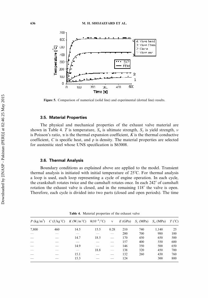
3.5. Material Properties
The physical and mechanical properties of the exhaust valve material areshown in Table 4. T is temperature, Su is ultimate strength, Sy is yield strength, nis Poisson’s ratio, a is the thermal expansion coefficient, K is the thermal conductivecoefficient, C is specific heat, and q is density. The material properties are selectedfor austenitic steel whose UNS specification is S63008.
3.6. Thermal Analysis
Boundary conditions as explained above are applied to the model. Transientthermal analysis is initiated with initial temperature of 25�C. For thermal analysisa loop is used, each loop representing a cycle of engine operation. In each cycle,the crankshaft rotates twice and the camshaft rotates once. In each 242� of camshaftrotation the exhaust valve is closed, and in the remaining 118� the valve is open.Therefore, each cycle is divided into two parts (closed and open periods). The time
Figure 5. Comparison of numerical (solid line) and experimental (dotted line) results.
Table 4. Material properties of the exhaust valve
P (kg=m3) C (J=kg �C) K (W=m �C) h(10�6=�C) v E (GPa) Sy (MPa) Su (MPa) T (�C)
7,800 460 14.5 15.5 0.28 210 740 1,140 25
— — — — — 200 700 980 100
— — 14.7 18.5 — 170 450 650 500
— — — — — 157 400 550 600
— — 14.9 — — 146 350 500 650
— — — 18.8 — 138 320 450 700
— — 15.1 — — 132 260 430 760
— — 15.3 — — 124 300 800
636 M. H. SHOJAEFARD ET AL.
Dow
nloa
ded
by [
INA
SP -
Pak
ista
n (P
ER
I)]
at 0
2:46
25
May
201
5

at the end of each part is calculated as
t1 ¼360� ði � 1Þ þ 242
6�Mð8Þ
t2 ¼360� ði � 1Þ þ 242þ 118
6�Mð9Þ
where M is the rotation speed of the camshaft, that is, 2,350 rpm, and i is the numberof the cycle. t1 is closed time of the valve and t2 is the open time of the valve.
To model the valve-open duration, the heat transfer contact coefficientbetween the valve and the seat is set to zero. The simulation starts by applying an
Figure 6. Procedure of thermal analysis.
THERMAL ANALYSIS OF ENGINE EXHAUST VALVE 637
Dow
nloa
ded
by [
INA
SP -
Pak
ista
n (P
ER
I)]
at 0
2:46
25
May
201
5

initial temperature of 25�C when the valve is closed. Then the extracted data from thevalve-closing period is applied to perform thermal analysis during the valve-openingperiod. The procedure of the thermal analysis is shown in Figure 6.
The thermal analysis continues until steady-state condition is reached. Thissteady-state condition is obtained after 5,000 cycles.
3.7. Thermal Stress Analysis
The solution of stresses resulting from the predicted temperature profile usedthe same model as the thermal analysis. Appropriate changes in boundary conditionsand degrees of freedom of the elements were made. Before changing the boundaryconditions, the elements must be changed to obtain the structural degrees of free-dom. In thermal analysis, all elements have a temperature degree of freedom. How-ever, for stress analysis the degrees of freedom of the elements will be translated in
Figure 7. Temperature profiles for valve head and stem at steady-state condition.
638 M. H. SHOJAEFARD ET AL.
Dow
nloa
ded
by [
INA
SP -
Pak
ista
n (P
ER
I)]
at 0
2:46
25
May
201
5

two directions. In addition, for stress analysis, the spring was considered in themodel. The boundary conditions are restraining at the valve seat and valve guide;therefore, the displacement value at these locations is zero. Furthermore, the freeend of the spring was restrained.
Figure 9. Variation of heat flow rate in (1) seat surface, (2) head, and (3) guide zone of the exhaust valve.
Figure 8. Variation of temperature at the exhaust valve during transient operation.
THERMAL ANALYSIS OF ENGINE EXHAUST VALVE 639
Dow
nloa
ded
by [
INA
SP -
Pak
ista
n (P
ER
I)]
at 0
2:46
25
May
201
5

Figure 10. Distribution of thermal stress (Pa) at steady-state condition: (a) radial stress; (b) axial stress; (c)
hoop stress.
640 M. H. SHOJAEFARD ET AL.
Dow
nloa
ded
by [
INA
SP -
Pak
ista
n (P
ER
I)]
at 0
2:46
25
May
201
5
After applying the structural boundary conditions, the temperature distri-bution at each time was applied to the model and solved for thermal stresses.
4. RESULTS
Figure 7 shows the valve temperature distribution at steady-state condition. Inthis figure, the valve temperature varies from 65�C around the top of the valve toits maximum temperature of about 700�C at the middle bottom area of the valve.Figure 8 shows that the temperature profiles for different parts of the exhaust valveas a function of time. The temperature reaches the steady-state condition after about130 s. This time is very small when compared with the work generated by the engine,which usually runs for several hours.
Figure 9 shows the variation of the heat flow rate through the exhaust valve viathe seat surface, valve head, and valve guide zone of the exhaust valve as a functionof time. It is concluded that the maximum heat is removed through the valve seatduring the closed period for the valve, while the contribution of the valve guide toremove heat is minimum.
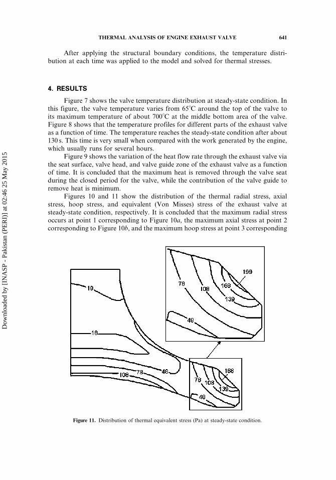
Figures 10 and 11 show the distribution of the thermal radial stress, axialstress, hoop stress, and equivalent (Von Misses) stress of the exhaust valve atsteady-state condition, respectively. It is concluded that the maximum radial stressoccurs at point 1 corresponding to Figure 10a, the maximum axial stress at point 2corresponding to Figure 10b, and the maximum hoop stress at point 3 corresponding
Figure 11. Distribution of thermal equivalent stress (Pa) at steady-state condition.
THERMAL ANALYSIS OF ENGINE EXHAUST VALVE 641
Dow
nloa
ded
by [
INA
SP -
Pak
ista
n (P
ER
I)]
at 0
2:46
25
May
201
5

Figure 12. Variation of thermal stress corresponding to Figure 10: (a) valve seat surface; (b) valve fillet
surface.
642 M. H. SHOJAEFARD ET AL.
Dow
nloa
ded
by [
INA
SP -
Pak
ista
n (P
ER
I)]
at 0
2:46
25
May
201
5

to Figure 10c. The maximum equivalent stress is about 208MPa, which isdeveloped in the hoop direction of the seat contact surface as shown in Figure11. This is due the fact that the temperature on the inner surface of the valve ishigher than in the other parts.
Figure 12 shows the variation of the thermal stresses at different parts of theexhaust valve such as the valve seat surface and valve fillet surface correspondingto Figure 10. They show that the stresses are negative at the beginning of the simula-tion. This is due to the fact that in the early phase of the simulation, the temperaturesat different parts of the exhaust valve surfaces are high.
5. CONCLUSION
Thermal analysis of the exhaust valve shows that the maximum temperature ofthe exhaust valve occurs at the stem of the valve. For these specific thermal bound-ary conditions, the maximum temperature of the exhaust valve is about 700�C. Atthe worst engine operating condition, maximum load and 4,700 rpm, the simulationreaches a steady-state condition after 130 s. This time is negligible when compared tothe continuous engine running time, which usually lasts for several hours.
The maximum thermal stress is developed at the valve seat contact zone of thevalve in the hoop direction, and its value is 208MPa. According to the yield strengthgiven in Table 1, this stress does not cause the valve material to yield. However, sincethe mentioned stress is positive, at the worst conditions for the cooling of the valvesuch as distortion of the seat, this stress causes radial cracks at the edge of the valve.
REFERENCES
1. J. M. Cherrie, Factors Influencing Valve Temperatures in Passenger Car Engines, SAEPaper 650484, 1965.
2. R. P. Worthen and T. N. Tunnecliffe, Temperature Controlled Engine Valves, SAE Paper820501, 1982.
3. Z. Johan, A. C. M. Moraes, J. C. Buell, and R. M. Ferencz, In-Cylinder Cold Flow Simu-lation Using a Finite Element Method, Comput. Meth. Appl. Mech. Eng., vol. 190,pp. 3069–3080, 2001.
4. R. Prasad and N. K. Samria, Heat Transfer and Stress Fields in the Inlet and ExhaustValves of a Semi-adiabatic Diesel Engine, Comput. Struct., vol. 34, no. 5, pp. 765–777,1990.
5. R. Prasad and N. K. Samria, Transient Heat Transfer Studies on a Diesel Engine Valve,Int. J. Mech. Sci., vol. 33, no. 3, pp. 179–195, 1991.
6. C. R. Ferguson and A. T. Kirkpatrick, Internal Combustion Engines, 2nd ed., Wiley, NewYork, 2001.
7. A. C. Alkidas, Intake-Valve Temperature and the Factors Affecting It, SAE Paper971729, 1997.
8. J. Cowart and W. Cheng, Intake Valve Thermal Behavior during Steady-State and Tran-sient Engine Operation, SAE Paper 1999-01-3643, 1999.
9. R. P. Worthen and D. G. Rauen, Measurement of Valve Temperatures and Strain in aFiring Engine, SAE Paper 860356, 1986.
10. H. Cheng-Hung and J. Tzann-Ming, Inverse Problem of Determining the Periodic Ther-mal Contact Conductance between Exhaust Valve and Seat in an Internal Combustion
THERMAL ANALYSIS OF ENGINE EXHAUST VALVE 643
Dow
nloa
ded
by [
INA
SP -
Pak
ista
n (P
ER
I)]
at 0
2:46
25
May
201
5

Engine, Paper 93-HT-35, Presented at the ASME Natl. Heat Transfer Conf., Atlanta,GA, 1993.
11. S. Imabeppu, H. Shimosono, Y. Hirano, K. Fujigaya, and K. Inoue, Development of aMethod for Predicting Heat Rejection to the Engine Coolant, SAE Paper 93114, 1993.
12. A. C. Alkidas, Thermal Loading of the Cylinder Head of a Spark-Ignition Engine, HeatTansfer Eng., vol. 3, no. 3–4, pp. 66–74, 1982.
13. P. J. Shayler, S. A. May, and T. Ma, Heat Transfer to the Combustion Chamber Walls inSpark lgnition Engines, SAE Paper 950686, 1986.
14. D. A. Kapadia and G. L. Borman, The Effect of Heat Transfer on the Steady Flowthrough a Poppet Valve, SAE Paper 670479, 1967.
15. J. Donea, An Arbitrary Lagrangian-Eulerian Finite Element Method for TransientDynamic Fluid-Structure Intractions, Comput. Meth. Appl. Mech. Eng., vol. 33,pp. 689–723, 1982.
16. R. W. Nichols, B. W. Ramsey, E. E. Marotta, and J. R. Wagner, Thermal PeriodicContact of Exhaust Valves in Spark Ignition Internal Combustion Engines for ImprovedControl Performance, AIAA Paper 2000-0878, 2000.
17. J. B. Heywood, Internal Combustion Engine Fundamentals, McGraw-Hill, New York,1988.
18. J. R. Howard, An Experimental Study of Heat Transfer through Periodically ContactingSurfaces, Int. J. Heat Mass Transfer, vol. 19, pp. 367–372, 1976.
19. W. M. Moses and R. R. Johnson, Experimental Study of the Transient Heat Transferacross Periodically Contacting Surfaces, J. Thermophy. Heat Transfer, vol. 2, no. 1,pp. 37–42, 1988.
20. R. D. Cook, Finite Element Modeling for Stress Analysis, Wiley, New York, 1995.21. ANSYS 6.1, User Manual, document, www.uic.edu=depts, 2002.22. D. Couedel, F. Danes, and J. P. Bardon, Experimental Study and Analysis of Heat Transfer
in a Valve-Seat Periodic Contact in an Internal Combustion Engine, Meeting ASME,Atlanta, GA, 1991.
23. P. J. Shayler, S. J. Christian, and T. Ma, A Model for the Investigation of Temperature,Heat Flow and Friction Characteristics during Engine Warm-up, SAE Paper 931153,1993.
24. S. V. Bohac, D. M. Baker, and D. N. Assanis, A Global Model for Steady State andTransient S.I. Engine Heat Transfer Studies, SAE Paper 960073, 1996.
25. I. K. Yoo, K. Simpson, M. Bell, and S. Majkowski, An Engine Coolant TemperatureModel and Application for Cooling System Diagnosis, SAE Paper 2000-01-0939, 2000.
26. H. Heisler, Advanced Engine Technology, Society of Automotive Engineers, HodderHeadline Group, London, 1995.
27. L. C. Yang, A. Hamada, and K. Ohtsubo, Engine Valve Temperature Simulation System,SAE Paper 2000-0100564, 2000.
28. I. Paradis, J. R. Wagner, and E. E. Marotta, Thermal Periodic Contact of Exhaust Valvesin Spark Ignition Air-Cooled Engines, J. Thermophys. Heat Transfer, vol. 16, no. 3,pp. 356–365, 2002.
29. C. Huang and T. Ju, An Inverse Problem of Simultaneously Estimating Contact Conduc-tance and Heat Transfer Coefficient of Exhaust Gases between Engine Exhaust Gas andValve, Int. J. Numer. Meth. Heat Transfer, vol. 38, no. 5, pp. 735–754, 1995.
644 M. H. SHOJAEFARD ET AL.
Dow
nloa
ded
by [
INA
SP -
Pak
ista
n (P
ER
I)]
at 0
2:46
25
May
201
5