transient stability analysis in microgrids using p-f … 4, issue 4 aug 2015 ijraet transient...
TRANSCRIPT

Volume 4, Issue 4 AUG 2015
IJRAET
Transient Stability Analysis In Microgrids Using P-F Droop Controller
P. Nagalakshmi PG Student [EPS], Dept. of EEE, BITS, proddatur, Andhra Pradesh, India.
B. Bhargava Reddy Assistant professor,HOD Dept. of EEE, BITS, Proddatur, Andhra Pradesh, India
A
Abstract— The present scenario is towards shifting centralised power generation (central grid) to distributed generation (micro grid) with smaller sources of capacity. The isolated micro grid is connected to main grid with inverters at the front end for efficient exchange of power sharing; power exchange among distributed generation (DG) sources in an isolated micro grid is possible with droop characteristics as per their capacity.The stability and operation aspects of converter-dominated microgrids (MGs), however, are faced by many challenges. Important among these, are the absence of physical inertia, comparable size of power converters, mutual interactions among generators islanding detection delays and large sudden disturbances associated with transition to islanded mode, grid restoration, and load power changes. Sources in the MGs use droop control to share power according to their capacity without any form of communication. This paper proposes a novel controller for inverters in DG for improving transient frequency response of the micro grid under consideration of large disturbances with considerable frequency deviations to validate the effectiveness of the proposed P-F rope controller simulation is carried out on MATLAB Simulink platform.
Index Term —DG(Distributed Generator), MATLAB SIMULINK, Transient frequency responses, Droop characteristics, P-F control.
I. INTRODUCTION
Power sharing among different DGs in an
isolated microgrid is possible by employing droop control or by using some centralized communication. Traditionally active power-frequency( P-ω) and reactive power-voltage (Q–V) droop is implemented to control frequency and voltage in DGs having a power-electronic interface Inverters do not have a rotating mass and, hence, have low inertia. Higher penetration of inverter-
based static sources in microgrid may result in poor voltage and frequency response during large disturbances. If the issues are not addressed, this transient response problem may develop into a transient stability problem. Microgrid transient stability depends on the DG technology and its control, its penetration level, type and location of fault, and nature of loads. The effect of high penetration of various DG technologies on transient stability of the system is studied. DGs based on synchronous machine reduce maximum frequency deviation at the expense of increasing oscillation duration (due to inertia), while inverter based DGs decrease rotor-angle deviations and improve voltage profile at the user end of the system on account of faster control and increased system damping, at the expense of increasing frequency deviations. Transient response of the system can also be improved by using energy storage devices, such as ultra- capacitors and battery alongside DGs. However in a large power system with a greater number of DGs, disturbance location consideration can make the storage-based solution ineffective and costly. Disturbances in such a scenario can result in large frequency deviations exceeding frequency and df/dt threshold, resulting in the tripping of generation or unnecessary load shedding. The concept of adding inertia virtually to reduce frequency deviations in microgrids by modifying inverter control has been reported in the literature as virtual synchronous generator virtual synchronous machine and synchro converters . Increasing inertia virtually in the inverter results in a reduction in maximum rotor speed deviation of the nearby source. The concept of adding inertia virtually by modifying the control strategy of existing inverters rather than having a dedicated inertial source has not been reported so far. Reference analyses the interaction problem of inverter and diesel generator-based sources.
Large - droop gain of diesel-based generator is shown to affect electromechanical modes and, hence, overall stability. Due to the time lag associated with synchronous generator control, microgrid stability deteriorates if the diesel generator participates more by increasing the gain.

Volume 4, Issue 4 AUG 2015
IJRAET
In case of planned islanding, the set points of DG of microgrid are adjusted (prior to islanding) to have a smooth transition. This results in minimum transients when the microgrid is moving from grid-connected mode to islanding mode. In case of unplanned islanding, the deviation in frequency and power swing depends on the supply-demand gap in the islanded network. It is possible to reduce the transient by using fast-acting converter interfaced DG units. A large variation in load/source within a microgrid may lead to a transient stability problem when it is islanded, and the same disturbance may pose a small-signal stability problem when it is grid connected. This paper proposes a control technique for inverter-based DGs to improve the frequency response of microgrid in islanding in addition to power management. The microgrid under study is modeled using the power system toolbox of Simulink/MATLAB with synchronous generator and inverters. The effect of the proposed strategy on system inertia, frequency deviation, and its rate of change are analyzed for a system with DGs based on synchronous machine and inverter through simulation. The effect of adding inertia on frequency oscillations and transient response is also investigated in the present study. The importance of inertia and its effect on improvement of transient response is discussed in Section II. The proposed droop control is presented in Section III. The simulation of the proposed scheme in an inverter and synchronous generator-based microgrid system is presented in Section IV.
II. INERTIA AND TRANSIENT RESPONSE OF MICROGRID
Rotational inertia is a measure of an object’s resistance to changes in the rotational speed. The relation between power, angular speed, and inertia of a power system is given by (1)
Where is the moment of inertia and is
the coefficient of friction loss of the synchronous generator; and are the synchronous and angular speed of the generator, respectively; is the mechanical power produced at the shaft; and is the electrical load seen by the generator and can be rewritten as (2)
The rate of change of speed and, hence,
system frequency deviation is inversely proportional to inertia. Stiff power grids maintain frequency and voltage during disturbances owing to large inertia and fast field control of synchronous
generators, respectively. Due to high inertia of rotors, synchronous generators store a large amount of kinetic energy. Whenever there is a load increase, the imbalance in mechanical and electrical power for a synchronous generator, leads to speed deceleration. Momentarily, the kinetic energy stored in the rotor will be utilized to compensate for this imbalance. Meanwhile, the governor increases the input mechanical power so that in steady state is equal to and the system stabilizes to a new frequency. Similarly, the field control of generators acts quickly to maintain system voltage during reactive power demand, such as induction motor starting or faults. Thus, power system frequency and voltage are regulated within a tight band.
III. DROOP CONTROL THEORY In microgrid, the system reliability and stability is achieved only by the voltage regulation when more micro sources are interconnected. This voltage regulation damps the reactive power oscillations and voltage. In a complex power system, when multiple DGs are attached to the microgrid, the power sharing among them is made properly with the help of a control strategy called droop control. Droop control also enables the system to disconnect smoothly and reconnect routinely to the complex power system.
The role of droop control in power sharing
is that it control the real power on the basis of frequency droop control and it controls the reactive power on the basis of voltage control.
The voltage and frequency can be
manipulated by regulating the real and reactive power of the system. This forms a conventional droop control equation.
In a transmission line, the real and reactive power are designed as:
sin21
xvvP
(3)
cos21
21
xvv
xvQ
(4)
In the above mentioned equation (3) and (4), Resistance (R) is neglected for an overhead transmission lines as it is much lower than inductance (L). Also the power angle δ is lesser, Therefore, sin δ = δ and cos δ = 1.
21vvxP
(5)
121 v
xQvv (6)
Hence from the above equation (5) and (6), it is clear that the power angle δ can be controlled by

Volume 4, Issue 4 AUG 2015
IJRAET
regulating real power P. Also the voltage V1 can be controlled through reactive power Q. dynamically, the frequency control leads to regulate the power angle and this in turn controls the real power flow . Finally, the frequency and voltage amplitude of the microgrid are manipulated by adjusting the real and reactive power autonomously. As a result, the frequency and voltage droop regulation can be determined as:
)( 00 PPkff p (7)
)( 00 QQkVV q (8)
where f, V = The frequency and voltage at a new operating point; P, Q = Active and reactive power at a new operating point; f0, V0 = Base frequency and voltage; P0, Q0= Temporary set points for the real and reactive power; Kp, Kq = Droop constant.
A. Droop Control Block Diagram
The droop control theory is explained with the block diagram as shown in Figure 1. This droop control block is composed of two function blocks:
Frequency droop control Output limit control
The central controller delivers the inputs such
as the system frequency (f) and the output of power generation (P), or feeder flow (FL) and set points. Inputs are local measurements of frequency (f) and power output (P), or feeder flow (FL), and the set points are provided by the central controller. The output of the current controller is current reference signal of the d-axis.
In power grid attached mode, the
microgrid frequency is same as the rated value, so that the power output (P) and the feeder flow (FL) are sustained to the fixed value. When the microgrid is detached from the power grid, the power mismatch are balanced by the droop control automatically. With this the system attain its steady state and finally the system frequency is restored to its rated value.
Figure1: The Droop Control Block Diagram
IV. MODIFIED DROOP CONTROL FOR IMPROVED TRANSIENT RESPONSE
In the proposed scheme, the droop gain is modified as a function of df/dt . This loop will be effective when |df/dt| exceeds a predetermined value C. The modified droop control law for inverter control is given
(9) Where
, for C
= , for C.
Fig.2. Droop gain variation with df/dt for different values of
Here, is the nominal droop gain, which gets modified only if the rate of change of frequency exceeds a threshold. Constants can be designed for each inverter based on their maximum power ratings and maximum-allowable

Volume 4, Issue 4 AUG 2015
IJRAET
frequency deviation. The value of can be determined using the following equation: (10)
(11)
Where is the minimum droop gain, and is the frequency deviation corresponding to
the maximum power change that the inverter can support while operating at nominal power. Fig.1 shows the variation of droop gain( ) with df/dt for different values of From equations (9) to (11) and fig.2,the following inferences can be made regarding the design of the controller:
The choice depends on the maximum rate of change of frequency
and inverter output-power limit which indirectly limits the minimum value of droop gain .
Amount of inertia added virtually to the system increases with an increase in . A lower value results in more peak overshoot in frequency while a higher value of results in oscillations in frequency. Hence, it is important to arrive at the optimal value of .
Minimum droop gain can be
chosen to prevent the inverter from exceeding its maximum power limit.
The microgrid can be operated within specified frequency limits by setting
.
The control block to incorporate the modified droop control in an inverter is shown in Fig. 3. The constant C is the predefined limit of . Under normal operation, the rate of change of frequency is below C and, hence, the comparator output remains at 0. Thus, the droop gain(m) is unchanged and the
Fig.3 Block diagram of modified P –ω droop control.
Fig. 4. System considered for simulation.
TABLE I :PARAMETERS OF MICROGRID
Load
case A case B case C
L1 300kw +j100kvar
800kw +j100kvar
500kw + j100kvar
L2 400kw +j100kvar
800kw +j200kvar
500kw + j100kvar
L3 400kw +j50kvar
800kw +j200kvar
600kw + j100kvar
L4 400kw +j100kvar
800kw +j100kvar
600kw + j100kvar
TABLE II :LOAD DETAILS
inverter works in traditional droop control mode. Subsequent to a large disturbance, if seen by the inverter exceeds C, the output of the comparator block changes to 1. As a result, “m”

Volume 4, Issue 4 AUG 2015
IJRAET
gets modified in proportion to as given by Eqn
8. This results in a decrease in droop gain (m) and, hence, lower deviations in inverter reference frequency ) from nominal frequency ) . To maintain lower frequency deviations, the corresponding inverter has to supply higher power ( ).Thus inertia gets added virtually to the system by modifying the droop gain of the inverter. Since large disturbances take time to settle, is decreased at predefined time steps to slowly reduce the added inertia to zero, so that the frequency slowly reaches its steady-state value.
TABLE III DROOP CONSTANTS AND IMPEDANCE
Parameters
Symbol
Value Inverter DC
voltage Vdc1, Vdc2
8kV
P-ω droop gain – DG1,DG2
m12 -15.0e-6 (rad/s)/W
P-Fdroop gain – DG1,DG2
n12 -1.55 e-4 V/Var
P-ω droop gain – SG1,SG2
m34 -25.8e-6 (rad/s)/w
P-Fdroop gain – SG1,SG2
n34 -2.3 e-4 V/Var
Impedance Z1
Z2
0.32+j 0.38(Ω)
0.96+j 1.13(Ω) Transformers TX1,TX2
TX3,TX4
3.3KV-11KV
0.4KV-11KV
VI. SYSTEM SIMULATION
The system consists of loads (L1 to L4) and DGs based with an inverter as the front end(DG1, DG2) and conventional synchronous generators (SG1, SG2).The details of rating of machines, loads, droop constants of inverters, and synchronous machines are given in Tables I-III. The block diagram of control strategy implemented for inverters is shown in Fig.6.P and Q calculated from sensed voltage and current, are used to obtain the reference voltage and phase angle using the droop control technique. Voltage magnitude and phase angle are regulated using an inner fast voltage-control loop which employs the proportional- integral (PI) controller. Capacitor current , with small gain, is fed back as shown in Fig.4 to provide damping..
In this paper, the proposed technique is
tested in two different scenarios when the
microgrid is islanded (unintentional) from the main grid. Case A: Microgrid Islanding
In this case, the microgrid is islanded at 1.5 s while exporting power to the grid. The frequency and voltage of the microgrid follow grid values before islanding. After islanding, the sources in the island must reduce their power quickly to cater to the remaining load. Inverters do not have slow electromechanical modes associated with synchronous generators. As a result, DG1 and DG2 reduce their power output quickly compared to the synchronous generators.
Fig 5.Frequency profile with inverter using traditional, P-f droop control.
As shown in Fig.5, when the microgrid is islanded, the traditional droop control leads the frequency to increase up to 50.8 Hz before it slowly reaches a new steady state at 50.5 Hz. In the microgrid, all of the sources must get disconnected from the microgrid when 50.5 for 0.16 s. This will lead to a complete blackout in the system which is actually not necessary. Virtual inertia of the system is reduced slowly to zero by decreasing in four steps at predefined instants (3.5, 5, 7, and 8.5 s), so that the frequency slowly reaches a new steady-state value. Case B: Microgrid Islanded While importing Power
Volume 4, Issue 4 AUG 2015
IJRAET
(a)
(b)
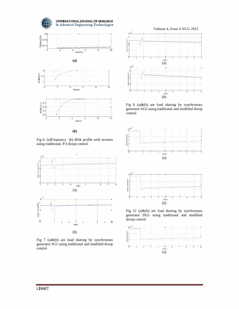
Fig 6. (a)Frequency (b) df/dt profile with inverter using traditional, P-f droop control.
(a)
(b)
Fig 7 (a)&(b) are load sharing by synchronous generator SG1 using traditional and modified droop control
(a)
(b)
Fig 8 (a)&(b) are load sharing by synchronous generator SG2 using traditional and modified droop control
(a)
(b)
Fig 12 (a)&(b) are load sharing by synchronous generator DG1 using traditional and modified droop control
(a)

Volume 4, Issue 4 AUG 2015
IJRAET
(b)
Fig 9 (a)&(b) are load sharing by synchronous generator DG2 using traditional and modified droop control
Fig 10 Current profile of DG1
Fig 11 Current profile of DG2
Fig 12 Current profile of SG1
Fig 13 Current profile of SG2
In this case, the microgrid is islanded at 1.5 s while importing power from the grid. The frequency and voltage of the microgrid follow grid values before islanding. After islanding, the sources in the island must increase power (depending on availability) quickly to cater to the remaining load.
When microgrid gets islanded, the traditional droop control leads the frequency to drop to 49.4 Hz at -1 Hz/s before it slowly reaches the new steady state of 49.5 Hz at 8 s. By using modified droop control, the drop in frequency is limited up to 49.6 Hz and to -0.8 Hz/s. Virtual inertia of the system is reduced slowly to zero by decreasing at predefined instants, so that the
frequency slowly reaches the new steady-state value.
VII. CONCLUSION
A new control technique to improve the transient response in microgrid in post islanding conditions is proposed. A microgrid consisting of a synchronous generator-based DG and inverter-based DG with loads is considered and is simulated in a Simulink/MATLAB environment. The proposed control technique is applied to inverter-based DGs. The droop gain of the inverter is modified based on the df/dt observed by the inverter during transition.
The results show that by employing modified droop control in inverters allows them to take the bulk of the power change transiently, at reduced frequency deviations. By adding virtual inertia as a function of df/dt , it is possible to reduce unwanted triggering of sources out of synchronism and to reduce load shedding in an islanded microgrid. This approach can reduce the short-term storage requirements of a microgrid where frequency is a major constraint, thus reducing the cost. The control can be designed to ensure microgrid operation within prescribed frequency limits, also making sure that the inverter is not overloaded.
REFERENCES
[1] R. H. Lasseter and P. Piagi, “Control and design of microgrid components” Madison, WI, PSERC project rep. no. PSERC-06–03, Jan. 2006. [2] S.-J. Ahn, J.-W.Park, I.-Y.Chung, S.-I.Moon, S.-H.Kang, and S.-R. Nam, “Power-sharing method of multiple distributed generators considering controlmodes and configurations of amicrogrid,” IEEE Trans.Power Del., vol. 25, no. 3, pp. 2007–2016, Jul. 2010. [3] M. Chandorkar, D. Divan, and R. Adapa, “Control of parallel connected inverters in standalone ac supply systems,” IEEE Trans. Ind.Appl., vol. 29, no. 1, pp. 136–143, Feb. 1993. [4] A. Engler and N. Soultanis, “Droop control in LV-grids,” in Proc. Int. Conf. Future Power Syst., 2005, pp. 1–6. [5] T. L. Vandoorn, J. D. M. De Kooning, B. Meersman, J. M. Guerrero, and L. Vandevelde, “Automatic power-sharing modification of P/V droop controllers in low-voltage resistive microgrids,” IEEE Trans.Power Del., vol. 27, no. 4, pp. 2318–2325, Oct. 2012. [6] K. Visscher and S. W. H. De Haan, “Virtual synchronous machines (VSG’s) for frequency stabilisation in future grids with a significant share of decentralized generation,” in Proc. IET-CIRED SeminarSmart-Grids Distrib., 2008, pp. 1–4. [7] H. P. Beck and R. Hesse, “Virtual synchronous machine,” in Proc. IEEE EPQU Conf., 2007, pp. 1–6.

Volume 4, Issue 4 AUG 2015
IJRAET
[8] Q.-C. Zhong and G.Weiss, “Synchronverters: Inverters that mimic synchronous generators,” IEEE Trans. Ind. Electron., vol. 58, no. 4, pp. 1259–1267, Apr. 2011. [9] M. Torres and L. A. C. Lopes, “Virtual synchronous generator control in autonomous wind-diesel power systems,” in Proc. IEEE-EPECConf., 2009, pp. 1–6. [10] Z. Miao, A. Domijan, and F. Lingling, “Investigation of microgridswith both inverter interfaced and direct ac-connected distributed energy resources,” IEEE Trans. Power Del., vol. 26, no. 3, pp. 1634–1642, Jul. 2011.