transformers autotransformers chokes · 1,3 62c0013000 285 290 335 200 265 12 21,0 1,6 62c0016000...
TRANSCRIPT
CHOKES
AUTOTRANSFORMERS
TRANSFORMERS
TRANSFORMERSAUTOTRANSFORMERSCHOKES
SINGLE-PHASE 136-153
THREE-PHASE 154-157
SINGLE-PHASE 158-159
THREE-PHASE 160-161
SINGLE-PHASE 162
THREE-PHASE 163-164
162-164
136-157
158-161
TECHNICAL DATA 165-169
TRANSFO
RMERS
TRANSFORMERS
136
STANDARDS
IEC 61558-1IEC 61558-2-4IEC 61558-2-6EN 61558-1
EN 61558-2-4EN 61558-2-6
TRANSFO
RMERS
TR 20
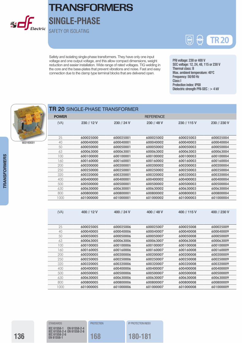
Safety and isolating single-phase transformers. They have only one input voltage and one output voltage, and this allow compact dimensions, weight reduction and easier installation. Wide range of rated voltages. TIG welding in the core and the base-plates that prevent vibrations and noise. Fast and easy connection due to the clamp type terminal blocks that are delivered open.
PRI voltage: 230 or 400 VSEC voltage: 12, 24, 48, 115 or 230 VThermal class: BMax. ambient temperature: 40°CFrequency: 50/60 HzClass IProtection index: IP00Dielectric strength PRI-SEC : > 4 kV
TR 20 SINGLE-PHASE TRANSFORMERPOWER REFERENCE
(VA) 230 // 12 V 230 // 24 V 230 // 48 V 230 // 115 V 230 // 230 V
25 600025000 600025001 600025002 600025003 60002500440 600040000 600040001 600040002 600040003 60004000450 600050000 600050001 600050002 600050003 60005000463 600063000 600063001 600063002 600063003 600063004100 600100000 600100001 600100002 600100003 600100004160 600160000 600160001 600160002 600160003 600160004200 600200000 600200001 600200002 600200003 600200004250 600250000 600250001 600250002 600250003 600250004320 600320000 600320001 600320002 600320003 600320004400 600400000 600400001 600400002 600400003 600400004500 600500000 600500001 600500002 600500003 600500004630 600630000 600630001 600630002 600630003 600630004800 600800000 600800001 600800002 600800003 6008000041000 601000000 601000001 601000002 601000003 601000004
(VA) 400 // 12 V 400 // 24 V 400 // 48 V 400 // 115 V 400 // 230 V
25 600025005 600025006 600025007 600025008 60002500940 600040005 600040006 600040007 600040008 60004000950 600050005 600050006 600050007 600050008 60005000963 600063005 600063006 600063007 600063008 600063009100 600100005 600100006 600100007 600100008 600100009160 600160005 600160006 600160007 600160008 600160009200 600200005 600200006 600200007 600200008 600200009250 600250005 600250006 600250007 600250008 600250009320 600320005 600320006 600320007 600320008 600320009400 600400005 600400006 600400007 600400008 600400009500 600500005 600500006 600500007 600500008 600500009630 600630005 600630006 600630007 600630008 600630009800 600800005 600800006 600800007 600800008 6008000091000 601000005 601000006 601000007 601000008 601000009
IP PROTECTION INDEX
180-181
PROTECTION
168
SINGLE-PHASESAFETY OR ISOLATING
600160001
TRANSFORMERS
137
STANDARDS
IEC 61558-1IEC 61558-2-4IEC 61558-2-6EN 61558-1
EN 61558-2-4EN 61558-2-6
TRANSFO
RMERS
TR 20
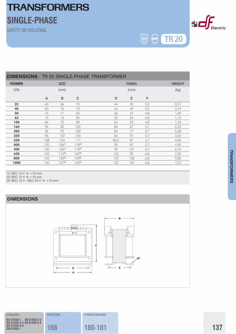
DIMENSIONS - TR 20 SINGLE-PHASE TRANSFORMERPOWER SIZE FIXING WEIGHT
(VA)
A
(mm)
B C D
(mm)
E F
(kg)
25 60 66 73 44 39 3,5 0,5140 60 76 73 44 49 3,5 0,7450 75 71 84 56 47 4,8 1,0063 75 76 84 56 54 4,8 1,10100 84 70 90 64 52 4,8 1,35160 96 82 100 84 67 5,7 2,23200 96 92 100 84 77 5,7 2,68250 96 107 100 84 91 5,7 3,35320 108 104 111 80,5 87 5,7 4,40400 120 106(1) 118(2) 90 87 5,7 4,90500 120 126(1) 118(2) 90 107 5,7 6,70630 150 114(3) 142(3) 122 92 6,8 7,50800 150 130(3) 142(3) 122 108 6,8 9,801000 150 157(3) 142(3) 122 135 6,8 13,2
(1) SEC 12 V ‡ +15 mm (2) SEC 12 V ‡ +10 mm (3) SEC 12 V - SEC 24 V ‡ +10 mm
IP PROTECTION INDEX
180-181
PROTECTION
168
SINGLE-PHASESAFETY OR ISOLATING
DIMENSIONS
D
A
C
E
øF
B

TRANSFORMERS
138
TRANSFO
RMERS
Control and safety or isolating single-phase transformers. They can supply high instantaneous power necessary for the correct operation of contactors and other switch and control gear. Great flexibility due to the double primary voltage and the serial-parallel connection. TIG welding in the core and the base-plates that prevent vibrations and noise. Fast and easy connection due to the clamp type terminal blocks.
PRI voltage: 0-230-400 VSEC voltage: 12-24, 24-48 or 115-230 VSEC serial or parallel connectionThermal class: BMax. ambient temperature: 40°CFrequency: 50/60 HzClass IProtection index: IP00Dielectric strength PRI-SEC: > 4 kV
TR 21 SINGLE-PHASE TRANSFORMER POWER INSTANT. POWER REFERENCE
(VA) (VA)
( 12-24 V ) ( 24-48 V ) ( 115-230 V )
40 75 610040000 610040001 61004000263 140 610063000 610063001 610063002100 220 610100000 610100001 610100002160 380 610160000 610160001 610160002200 450 610200000 610200001 610200002250 650 610250000 610250001 610250002320 850 610320000 610320001 610320002400 1000 610400000 610400001 610400002500 1400 610500000 610500001 610500002630 1600 610630000 610630001 610630002800 2400 610800000 610800001 6108000021000 3300 611000000 611000001 611000002
SECONDARY CONNECTION POSSIBILITIES EXAMPLE: TRANSFORMER 230-400//12-24 V 500 VA (610500000)
SERIAL CONNECTION PARALLEL CONNECTION
400 V
230 V
0
24 V500VA20,83 A
400 V
230 V
0
12 V500VA41,66 A
TR 21CONTROL
SINGLE-PHASE
STANDARDS
IEC 61558-1IEC 61558-2-2IEC 61558-2-4IEC 61558-2-6
EN 61558-1EN 61558-2-2EN 61558-2-4EN 61558-2-6
SELECTION GUIDE
165
PROTECTION
168
IP PROTECTION INDEX
180-181
610250001
TRANSFORMERS
139
IP PROTECTION INDEX
180-181
TRANSFO
RMERS
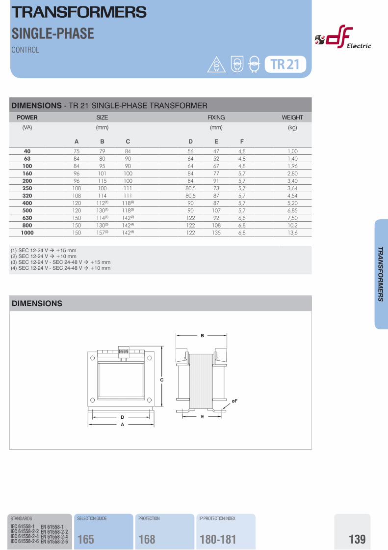
DIMENSIONS - TR 21 SINGLE-PHASE TRANSFORMER POWER SIZE FIXING WEIGHT
(VA)
A
(mm)
B C D
(mm)
E F
(kg)
40 75 79 84 56 47 4,8 1,0063 84 80 90 64 52 4,8 1,40100 84 95 90 64 67 4,8 1,96160 96 101 100 84 77 5,7 2,80200 96 115 100 84 91 5,7 3,40250 108 100 111 80,5 73 5,7 3,64320 108 114 111 80,5 87 5,7 4,54400 120 112(1) 118(2) 90 87 5,7 5,20500 120 130(1) 118(2) 90 107 5,7 6,85630 150 114(1) 142(2) 122 92 6,8 7,50800 150 130(3) 142(4) 122 108 6,8 10,21000 150 157(3) 142(4) 122 135 6,8 13,6
(1) SEC 12-24 V ‡ +15 mm (2) SEC 12-24 V ‡ +10 mm (3) SEC 12-24 V - SEC 24-48 V ‡ +15 mm (4) SEC 12-24 V - SEC 24-48 V ‡ +10 mm
TR 21CONTROL
SINGLE-PHASE
STANDARDS
IEC 61558-1IEC 61558-2-2IEC 61558-2-4IEC 61558-2-6
EN 61558-1EN 61558-2-2EN 61558-2-4EN 61558-2-6
SELECTION GUIDE
165
PROTECTION
168
DIMENSIONS
C
D
A
E
øF
B
TRANSFORMERS
140
TRANSFO
RMERS
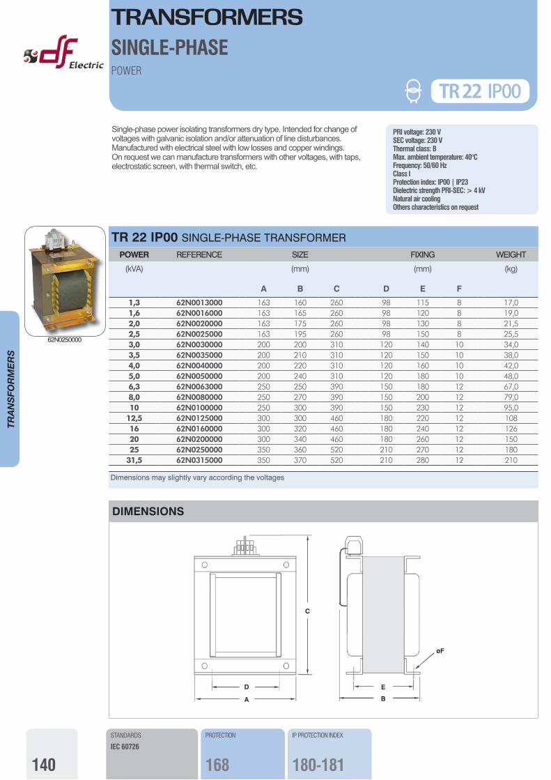
Single-phase power isolating transformers dry type. Intended for change of voltages with galvanic isolation and/or attenuation of line disturbances.Manufactured with electrical steel with low losses and copper windings. On request we can manufacture transformers with other voltages, with taps, electrostatic screen, with thermal switch, etc.
PRI voltage: 230 VSEC voltage: 230 VThermal class: BMax. ambient temperature: 40°CFrequency: 50/60 HzClass IProtection index: IP00 | IP23Dielectric strength PRI-SEC: > 4 kVNatural air coolingOthers characteristics on request
TR 22 IP00 SINGLE-PHASE TRANSFORMER POWER REFERENCE SIZE FIXING WEIGHT
(kVA)
A
(mm)
B C D
(mm)
E F
(kg)
1,3 62N0013000 163 160 260 98 115 8 17,01,6 62N0016000 163 165 260 98 120 8 19,02,0 62N0020000 163 175 260 98 130 8 21,52,5 62N0025000 163 195 260 98 150 8 25,53,0 62N0030000 200 200 310 120 140 10 34,03,5 62N0035000 200 210 310 120 150 10 38,04,0 62N0040000 200 220 310 120 160 10 42,05,0 62N0050000 200 240 310 120 180 10 48,06,3 62N0063000 250 250 390 150 180 12 67,08,0 62N0080000 250 270 390 150 200 12 79,010 62N0100000 250 300 390 150 230 12 95,0
12,5 62N0125000 300 300 460 180 220 12 10816 62N0160000 300 320 460 180 240 12 12620 62N0200000 300 340 460 180 260 12 15025 62N0250000 350 360 520 210 270 12 180
31,5 62N0315000 350 370 520 210 280 12 210
Dimensions may slightly vary according the voltages
DIMENSIONS
D
A
E
øF
C
B
POWER
TR 22 IP00
STANDARDS
IEC 60726
IP PROTECTION INDEX
180-181
PROTECTION
168
SINGLE-PHASE
62N0250000
TRANSFORMERS
141
TRANSFO
RMERS
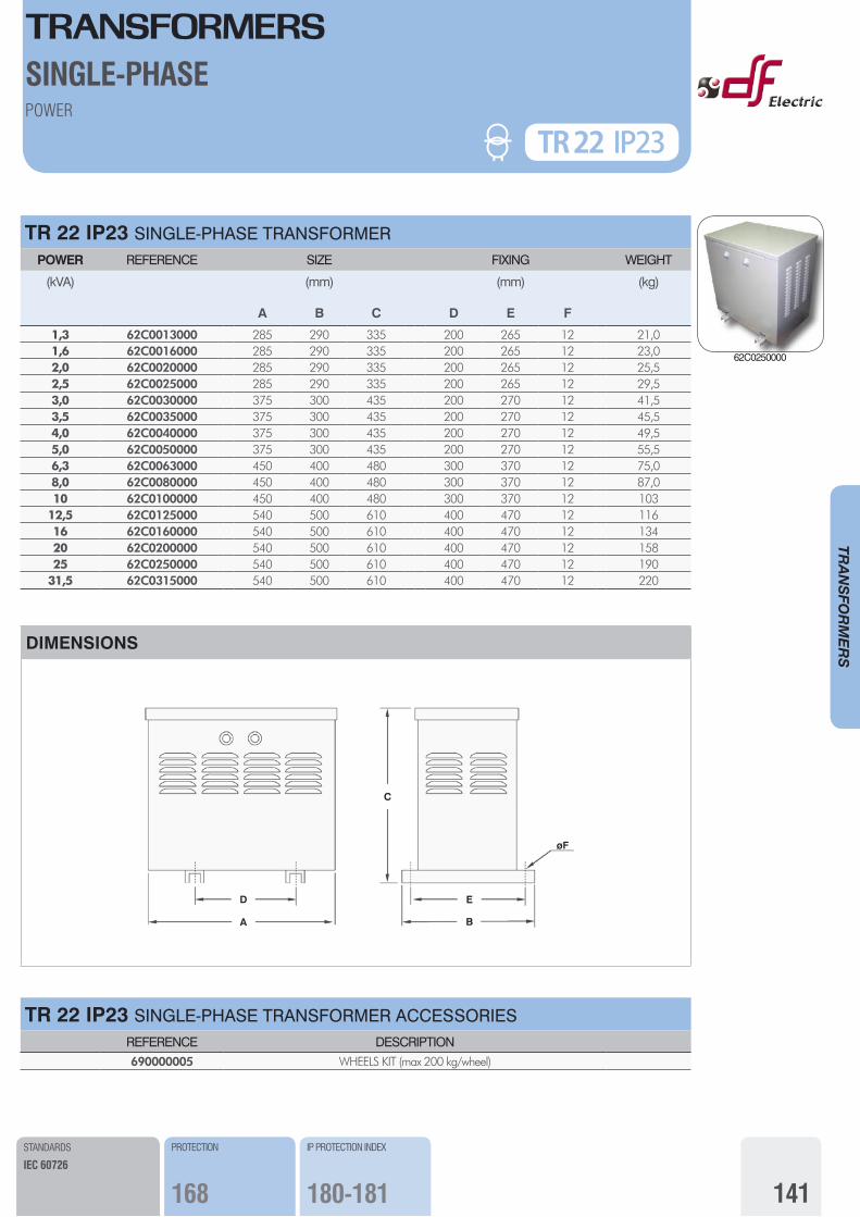
TR 22 IP23 SINGLE-PHASE TRANSFORMER POWER REFERENCE SIZE FIXING WEIGHT
(kVA)
A
(mm)
B C D
(mm)
E F
(kg)
1,3 62C0013000 285 290 335 200 265 12 21,01,6 62C0016000 285 290 335 200 265 12 23,02,0 62C0020000 285 290 335 200 265 12 25,52,5 62C0025000 285 290 335 200 265 12 29,53,0 62C0030000 375 300 435 200 270 12 41,53,5 62C0035000 375 300 435 200 270 12 45,54,0 62C0040000 375 300 435 200 270 12 49,55,0 62C0050000 375 300 435 200 270 12 55,56,3 62C0063000 450 400 480 300 370 12 75,08,0 62C0080000 450 400 480 300 370 12 87,010 62C0100000 450 400 480 300 370 12 103
12,5 62C0125000 540 500 610 400 470 12 11616 62C0160000 540 500 610 400 470 12 13420 62C0200000 540 500 610 400 470 12 15825 62C0250000 540 500 610 400 470 12 190
31,5 62C0315000 540 500 610 400 470 12 220
POWER
STANDARDS
IEC 60726
PROTECTION
168
IP PROTECTION INDEX
180-181
TR 22 IP23
SINGLE-PHASE
DIMENSIONS
D
A
E
øF
C
B
TR 22 IP23 SINGLE-PHASE TRANSFORMER ACCESSORIESREFERENCE DESCRIPTION690000005 WHEELS KIT (max 200 kg/wheel)
62C0250000
TRANSFORMERS
142
TRANSFO
RMERS
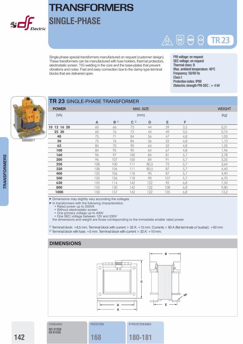
Single-phase special transformers manufactured on request (customer design).These transformers can be manufactured with fuse holders, thermal protectors, electrostatic screen. TIG welding in the core and the base-plates that prevent vibrations and noise. Fast and easy connection due to the clamp type terminal blocks that are delivered open.
Ñ Dimensions may slightly vary according the voltages Ñ In transformers with the following characteristics: • Rated power up to 250VA • Without electrostatic screen • One primary voltage up to 400V • One SEC voltage between 12V and 230V the dimensions and weight are those corresponding to the immediate smaller rated power.
Å Terminal block: +8,5 mm. Terminal block with current > 32 A: +15 mm. Currents > 80 A (flat terminals or busbar): +50 mm Ç Terminal block with fuse: +5 mm. Terminal block with current > 32 A: +10 mm.
TR 23 SINGLE-PHASE TRANSFORMER POWER MAX. SIZE WEIGHT
(VA) (mm) (kg)
A B Å C Ç D E F10 12 16 20 60 66 73 44 39 3,5 0,51
25 30 60 76 73 44 49 3,5 0,7440 75 71 84 56 47 4,8 1,0050 75 76 84 56 52 4,8 1,1063 84 70 90 64 52 4,8 1,35100 84 95 90 64 67 4,8 1,96160 96 97 100 84 81 5,7 2,78200 96 107 100 84 91 5,7 3,35250 108 100 111 80,5 73 5,7 3,64320 108 104 111 80,5 87 5,7 4,40400 120 106 118 90 87 5,7 4,90500 120 126 118 90 107 5,7 6,70630 150 114 142 122 92 6,8 7,50800 150 130 142 122 108 6,8 9,801000 150 157 142 122 135 6,8 13,2
PRI voltage: on requestSEC voltage: on requestThermal class: BMax. ambient temperature: 40°CFrequency: 50/60 HzClass IProtection index: IP00Dielectric strength PRI-SEC : > 4 kV
TR 23
STANDARDS
IEC 61558EN 61558
IP PROTECTION INDEX
180-181
PROTECTION
168
SINGLE-PHASE
DIMENSIONS
D
A
C
E
øF
B
TR 23
630050017
TRANSFORMERS
143
TRANSFO
RMERS
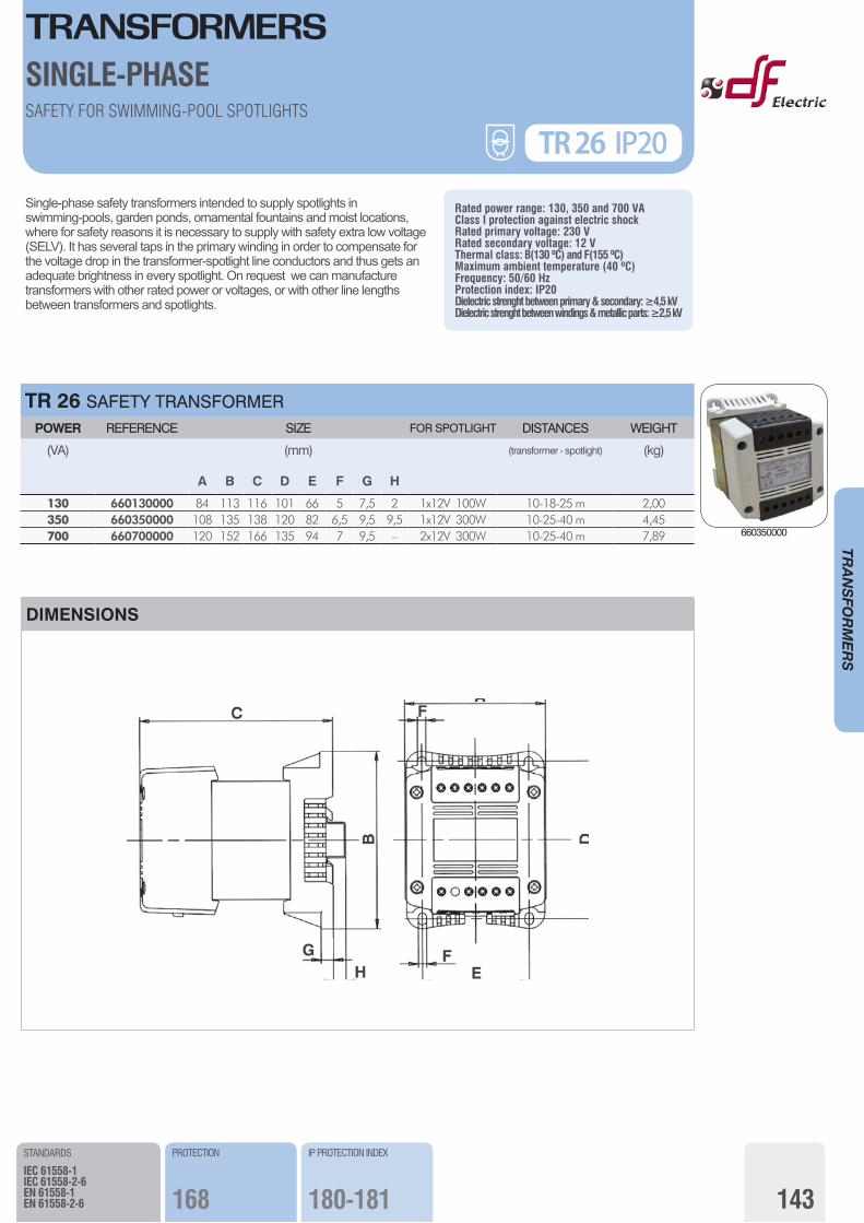
Single-phase safety transformers intended to supply spotlights in swimming-pools, garden ponds, ornamental fountains and moist locations, where for safety reasons it is necessary to supply with safety extra low voltage (SELV). It has several taps in the primary winding in order to compensate for the voltage drop in the transformer-spotlight line conductors and thus gets an adequate brightness in every spotlight. On request we can manufacture transformers with other rated power or voltages, or with other line lengths between transformers and spotlights.
Rated power range: 130, 350 and 700 VAClass I protection against electric shockRated primary voltage: 230 VRated secondary voltage: 12 VThermal class: B(130 ºC) and F(155 ºC)Maximum ambient temperature (40 ºC)Frequency: 50/60 HzProtection index: IP20Dielectric strenght between primary & secondary: ≥4,5 kVDielectric strenght between windings & metallic parts: ≥2,5 kV
TR 26 SAFETY TRANSFORMER POWER REFERENCE SIZE FOR SPOTLIGHT DISTANCES WEIGHT
(VA) (mm) (transformer - spotlight) (kg)
A B C D E F G H
130 660130000 84 113 116 101 66 5 7,5 2 1x12V 100W 10-18-25 m 2,00350 660350000 108 135 138 120 82 6,5 9,5 9,5 1x12V 300W 10-25-40 m 4,45700 660700000 120 152 166 135 94 7 9,5 – 2x12V 300W 10-25-40 m 7,89
SAFETY FOR SWIMMING-POOL SPOTLIGHTS
TR 26 IP20
STANDARDS
IEC 61558-1IEC 61558-2-6EN 61558-1EN 61558-2-6
IP PROTECTION INDEX
180-181
PROTECTION
168
SINGLE-PHASE
DIMENSIONS
660350000
TRANSFORMERSTRANSFORMERS SINGLE-PHASE
144
TRANSFO
RMERS
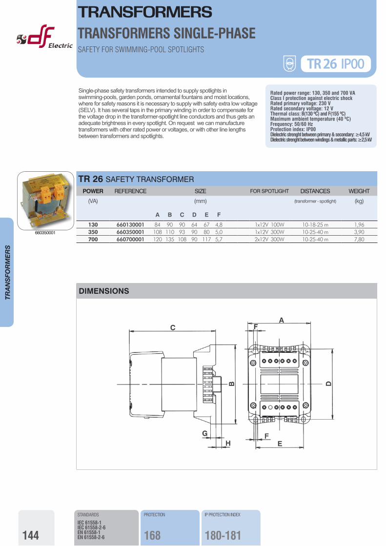
Single-phase safety transformers intended to supply spotlights in swimming-pools, garden ponds, ornamental fountains and moist locations, where for safety reasons it is necessary to supply with safety extra low voltage (SELV). It has several taps in the primary winding in order to compensate for the voltage drop in the transformer-spotlight line conductors and thus gets an adequate brightness in every spotlight. On request we can manufacture transformers with other rated power or voltages, or with other line lengths between transformers and spotlights.
Rated power range: 130, 350 and 700 VAClass I protection against electric shockRated primary voltage: 230 VRated secondary voltage: 12 VThermal class: B(130 ºC) and F(155 ºC)Maximum ambient temperature (40 ºC)Frequency: 50/60 HzProtection index: IP00Dielectric strenght between primary & secondary: ≥4,5 kVDielectric strenght between windings & metallic parts: ≥2,5 kV
TR 26 SAFETY TRANSFORMER POWER REFERENCE SIZE FOR SPOTLIGHT DISTANCES WEIGHT
(VA) (mm) (transformer - spotlight) (kg)
A B C D E F
130 660130001 84 90 90 64 67 4,8 1x12V 100W 10-18-25 m 1,96350 660350001 108 110 93 90 80 5,0 1x12V 300W 10-25-40 m 3,90700 660700001 120 135 108 90 117 5,7 2x12V 300W 10-25-40 m 7,80
DIMENSIONS
TR 26 IP00
STANDARDS
IEC 61558-1IEC 61558-2-6EN 61558-1EN 61558-2-6
IP PROTECTION INDEX
?
PROTECTION
166
STANDARDS
IEC 61558-1IEC 61558-2-6EN 61558-1EN 61558-2-6
IP PROTECTION INDEX
180-181
PROTECTION
168
SAFETY FOR SWIMMING-POOL SPOTLIGHTS
NEW660350001
TRANSFORMERSTRANSFORMERS SINGLE-PHASE
145
TRANSFO
RMERS
SAFETY FOR SWIMMING-POOL SPOTLIGHTS
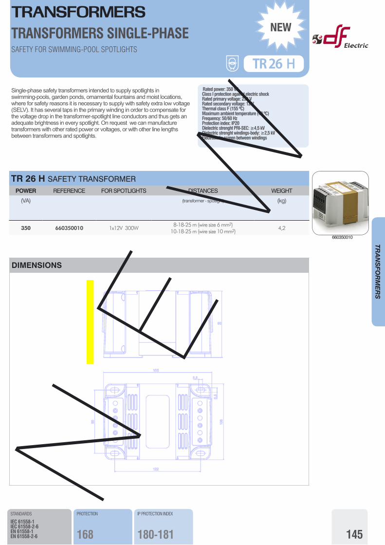
Single-phase safety transformers intended to supply spotlights in swimming-pools, garden ponds, ornamental fountains and moist locations, where for safety reasons it is necessary to supply with safety extra low voltage (SELV). It has several taps in the primary winding in order to compensate for the voltage drop in the transformer-spotlight line conductors and thus gets an adequate brightness in every spotlight. On request we can manufacture transformers with other rated power or voltages, or with other line lengths between transformers and spotlights.
Rated power: 350 VAClass I protection against electric shockRated primary voltage: 230 VRated secondary voltage: 12 VThermal class F (155 ºC)Maximum ambient temperature (40 ºC)Frequency: 50/60 HzProtection index: IP20Dielectric strenght PRI-SEC: ≥4,5 kVDielectric strenght windings-body: ≥2,5 kVElectrostatic screen between windings
TR 26 H SAFETY TRANSFORMERPOWER REFERENCE FOR SPOTLIGHTS DISTANCES WEIGHT
(VA) (transformer - spotlight) (kg)
350 660350010 1x12V 300W8-18-25 m (wire size 6 mm2)
10-18-25 m (wire size 10 mm2)4,2
DIMENSIONS
STANDARDS
IEC 61558-1IEC 61558-2-6EN 61558-1EN 61558-2-6
IP PROTECTION INDEX
?
PROTECTION
166
STANDARDS
IEC 61558-1IEC 61558-2-6EN 61558-1EN 61558-2-6
IP PROTECTION INDEX
180-181
PROTECTION
168
TR 26 H
NEW
NEW 660350010
TRANSFORMERS
146
TRANSFO
RMERS
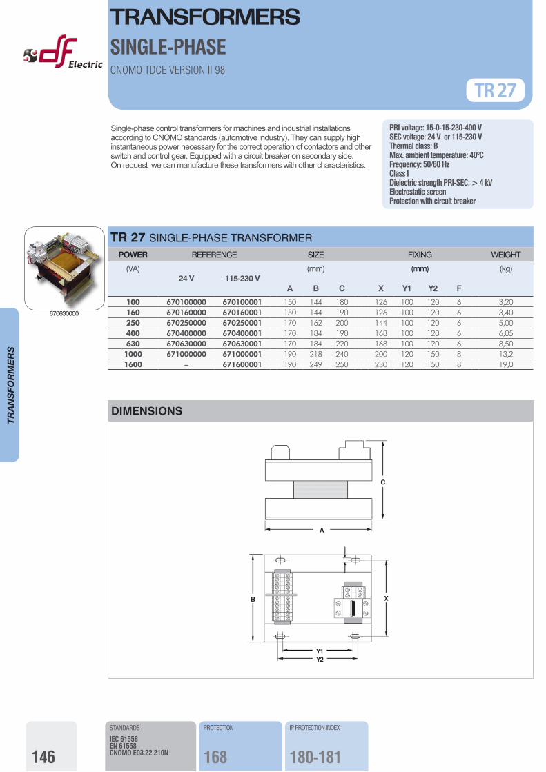
Single-phase control transformers for machines and industrial installations according to CNOMO standards (automotive industry). They can supply high instantaneous power necessary for the correct operation of contactors and other switch and control gear. Equipped with a circuit breaker on secondary side.On request we can manufacture these transformers with other characteristics.
TR 27 SINGLE-PHASE TRANSFORMER POWER REFERENCE SIZE FIXING WEIGHT
(VA)24 V 115-230 V
A
(mm)
B C X Y1 Y2 F
(kg)
100 670100000 670100001 150 144 180 126 100 120 6 3,20160 670160000 670160001 150 144 190 126 100 120 6 3,40250 670250000 670250001 170 162 200 144 100 120 6 5,00400 670400000 670400001 170 184 190 168 100 120 6 6,05630 670630000 670630001 170 184 220 168 100 120 6 8,501000 671000000 671000001 190 218 240 200 120 150 8 13,21600 – 671600001 190 249 250 230 120 150 8 19,0
(mm)
PRI voltage: 15-0-15-230-400 VSEC voltage: 24 V or 115-230 VThermal class: BMax. ambient temperature: 40°CFrequency: 50/60 HzClass IDielectric strength PRI-SEC: > 4 kVElectrostatic screenProtection with circuit breaker
CNOMO TDCE VERSION II 98
TR 27
STANDARDS
IEC 61558EN 61558CNOMO E03.22.210N
PROTECTION
168
IP PROTECTION INDEX
180-181
F
DIMENSIONS
Y1
A
C
B
Y2
X
SINGLE-PHASE
NEW670630000
TRANSFORMERS
147
TRANSFO
RMERS
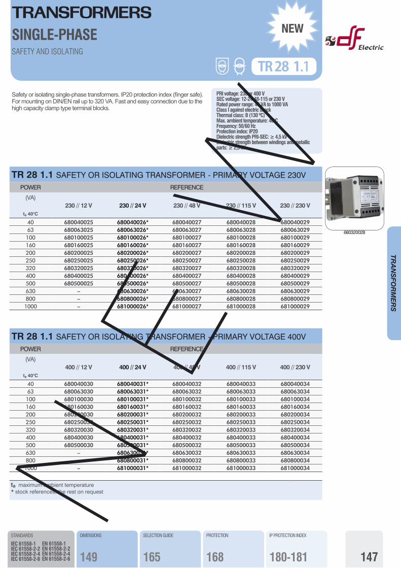
Safety or isolating single-phase transformers. IP20 protection index (finger safe). For mounting on DIN/EN rail up to 320 VA. Fast and easy connection due to the high capacity clamp type terminal blocks.
TR 28 1.1 SAFETY OR ISOLATING TRANSFORMER - PRIMARY VOLTAGE 230VPOWER REFERENCE
(VA)230 // 12 V 230 // 24 V 230 // 48 V 230 // 115 V 230 // 230 V
ta 40°C
40 680040025 680040026* 680040027 680040028 68004002963 680063025 680063026* 680063027 680063028 680063029100 680100025 680100026* 680100027 680100028 680100029160 680160025 680160026* 680160027 680160028 680160029200 680200025 680200026* 680200027 680200028 680200029250 680250025 680250026* 680250027 680250028 680250029320 680320025 680320026* 680320027 680320028 680320029400 680400025 680400026* 680400027 680400028 680400029500 680500025 680500026* 680500027 680500028 680500029630 – 680630026* 680630027 680630028 680630029800 – 680800026* 680800027 680800028 6808000291000 – 681000026* 681000027 681000028 681000029
SAFETY AND ISOLATING
STANDARDS
IEC 61558-1IEC 61558-2-2IEC 61558-2-4IEC 61558-2-6
EN 61558-1EN 61558-2-2EN 61558-2-4EN 61558-2-6
PRI voltage: 230 or 400 VSEC voltage: 12-24-48-115 or 230 VRated power range: 40 VA to 1000 VAClass I against electric shockThermal class: B (130 ºC)Max. ambient temperature: 40°CFrequency: 50/60 HzProtection index: IP20Dielectric strength PRI-SEC: ≥ 4,5 kVDielectric strength between windings and metallic parts: ≥ 2,5 kV
TR 28 1.1
SINGLE-PHASE
TR 28 1.1 SAFETY OR ISOLATING TRANSFORMER - PRIMARY VOLTAGE 400VPOWER REFERENCE
(VA)400 // 12 V 400 // 24 V 400 // 48 V 400 // 115 V 400 // 230 V
ta 40°C
40 680040030 680040031* 680040032 680040033 68004003463 680063030 680063031* 680063032 680063033 680063034100 680100030 680100031* 680100032 680100033 680100034160 680160030 680160031* 680160032 680160033 680160034200 680200030 680200031* 680200032 680200033 680200034250 680250030 680250031* 680250032 680250033 680250034320 680320030 680320031* 680320032 680320033 680320034400 680400030 680400031* 680400032 680400033 680400034500 680500030 680500031* 680500032 680500033 680500034630 – 680630031* 680630032 680630033 680630034800 – 680800031* 680800032 680800033 6808000341000 – 681000031* 681000032 681000033 681000034
NEW
DIMENSIONS
149
SELECTION GUIDE
165
IP PROTECTION INDEX
180-181
PROTECTION
168
ta maximum ambient temperature * stock references, the rest on requestN
EW 680320028
TRANSFORMERS
148
TRANSFO
RMERS
STANDARDS
IEC 61558-1IEC 61558-2-2IEC 61558-2-4IEC 61558-2-6
EN 61558-1EN 61558-2-2EN 61558-2-4EN 61558-2-6
CONTROL AND SAFETY OR ISOLATING
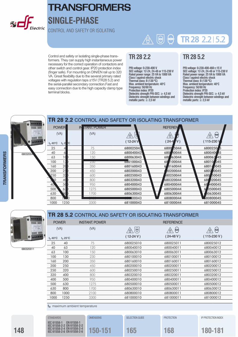
Control and safety or isolating single-phase trans-formers. They can supply high instantaneous power necessary for the correct operation of contactors and other switch and control gear. IP20 protection index (finger safe). For mounting on DIN/EN rail up to 320 VA. Great flexibility due to the several primary rated voltages with regulation taps ±15V (TR28 5.2) and the serial-parallel secondary connection.Fast and easy connection due to the high capacity clamp type terminal blocks.
TR 28 2.2 | 5.2
SINGLE-PHASE
TR 28 2.2 CONTROL AND SAFETY OR ISOLATING TRANSFORMER POWER INSTANT. POWER REFERENCE
(VA) (VA)
( 12-24 V ) ( 24-48 V ) ( 115-230 V )ta 40°C ta 25°C
25 40 75 680025043 680025044 68002504540 63 120 680040043 680040044 68004004563 100 150 680063043 680063044 680063045100 130 230 680100043 680100044 680100045160 200 350 680160043 680160044 680160045200 250 450 680200043 680200044 680200045250 320 600 680250043 680250044 680250045320 400 800 680320043 680320044 680320045400 500 950 680400043 680400044 680400045500 630 1275 680500043 680500044 680500045630 800 1700 680630043 680630044 680630045800 1000 2100 680800043 680800044 6808000451000 1250 3300 681000043 681000044 681000045
ta maximum ambient temperature
TR 28 5.2 CONTROL AND SAFETY OR ISOLATING TRANSFORMER POWER INSTANT. POWER REFERENCE
(VA) (VA)
( 12-24 V ) ( 24-48 V ) ( 115-230 V )ta 40°C ta 25°C
25 40 75 680025010 680025011 68002501240 63 120 680040010 680040011 68004001263 100 150 680063010 680063011 680063012100 130 230 680100010 680100011 680100012160 200 350 680160010 680160011 680160012200 250 450 680200010 680200011 680200012250 320 600 680250010 680250011 680250012320 400 800 680320010 680320011 680320012400 500 950 680400010 680400011 680400012500 630 1275 680500010 680500011 680500012630 800 1700 680630010 680630011 680630012800 1000 2100 680800010 680800011 6808000121000 1250 3300 681000010 681000011 681000012
TR 28 2.2
PRI voltage: 0-230-400 VSEC voltage: 12-24, 24-48 or 115-230 VRated power range: 25 VA to 1000 VAClass I against electric shockThermal class: B (130 ºC)Max. ambient temperature: 40°CFrequency: 50/60 HzProtection index: IP20Dielectric strength PRI-SEC: ≥ 4,5 kVDielectric strength between windings and metallic parts: ≥ 2,5 kV
TR 28 5.2
PRI voltage: 0-230-400-460±15 VSEC voltage: 12-24, 24-48 or 115-230 VRated power range: 25 VA to 1000 VAClass I against electric shockThermal class: B (130 ºC)Max. ambient temperature: 40°CFrequency: 50/60 HzProtection index: IP20Dielectric strength PRI-SEC: ≥ 4,5 kVDielectric strength between windings and metallic parts: ≥ 2,5 kV
DIMENSIONS
150-151
SELECTION GUIDE
165
IP PROTECTION INDEX
180-181
PROTECTION
168
680320044
680320011
NEW
TRANSFORMERS
149
TRANSFO
RMERS
DIMENSIONS
STANDARDS
IEC 61558-1IEC 61558-2-2IEC 61558-2-4IEC 61558-2-6
EN 61558-1EN 61558-2-2EN 61558-2-4EN 61558-2-6
TR 28 1.1
SINGLE-PHASE
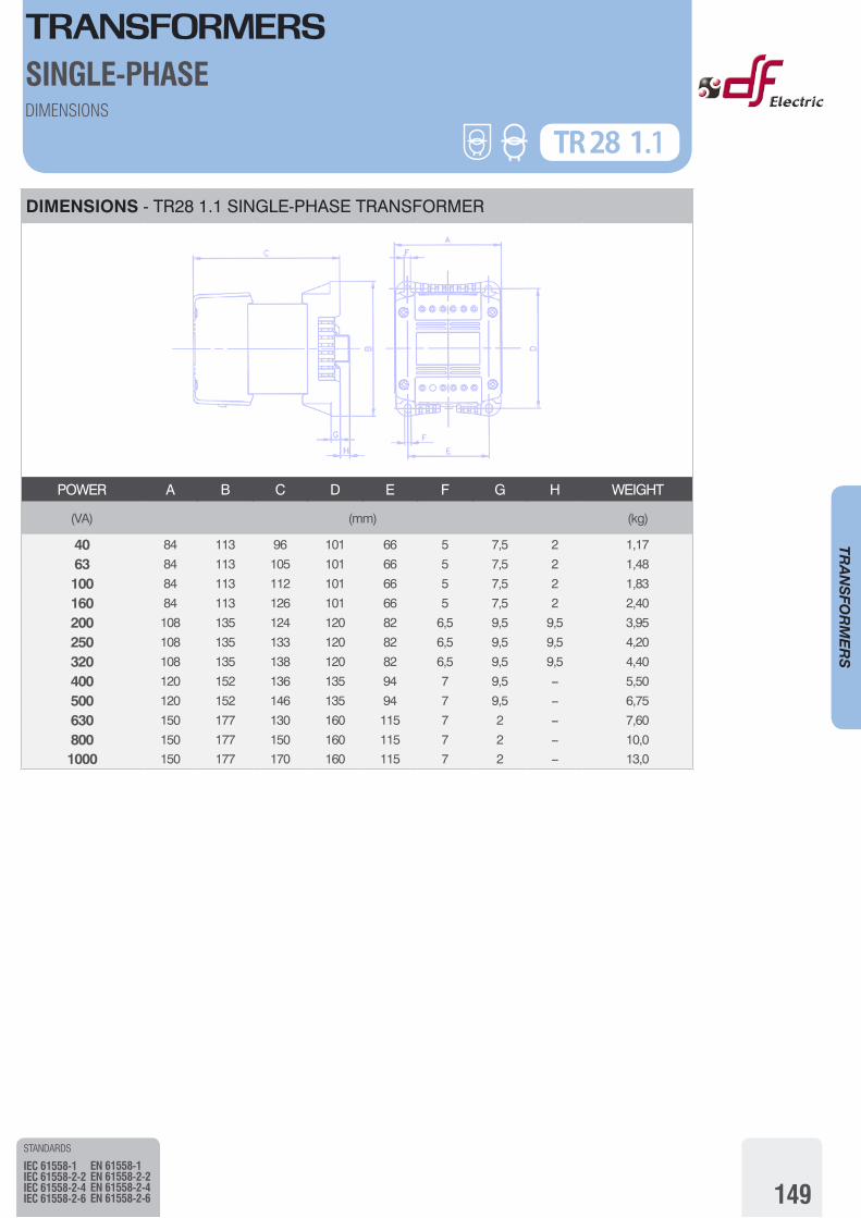
DIMENSIONS - TR28 1.1 SINGLE-PHASE TRANSFORMER
POWER A B C D E F G H WEIGHT
(VA) (mm) (kg)
40 84 113 96 101 66 5 7,5 2 1,17
63 84 113 105 101 66 5 7,5 2 1,48
100 84 113 112 101 66 5 7,5 2 1,83
160 84 113 126 101 66 5 7,5 2 2,40
200 108 135 124 120 82 6,5 9,5 9,5 3,95
250 108 135 133 120 82 6,5 9,5 9,5 4,20
320 108 135 138 120 82 6,5 9,5 9,5 4,40
400 120 152 136 135 94 7 9,5 – 5,50
500 120 152 146 135 94 7 9,5 – 6,75
630 150 177 130 160 115 7 2 – 7,60
800 150 177 150 160 115 7 2 – 10,0
1000 150 177 170 160 115 7 2 – 13,0
TRANSFORMERSTRANSFORMERS SINGLE-PHASE
150
TRANSFO
RMERS
DIMENSIONSCONNECTION POSSIBILITIES TR 28 2.2
STANDARDS
IEC 61558-1IEC 61558-2-2IEC 61558-2-4IEC 61558-2-6
EN 61558-1EN 61558-2-2EN 61558-2-4EN 61558-2-6
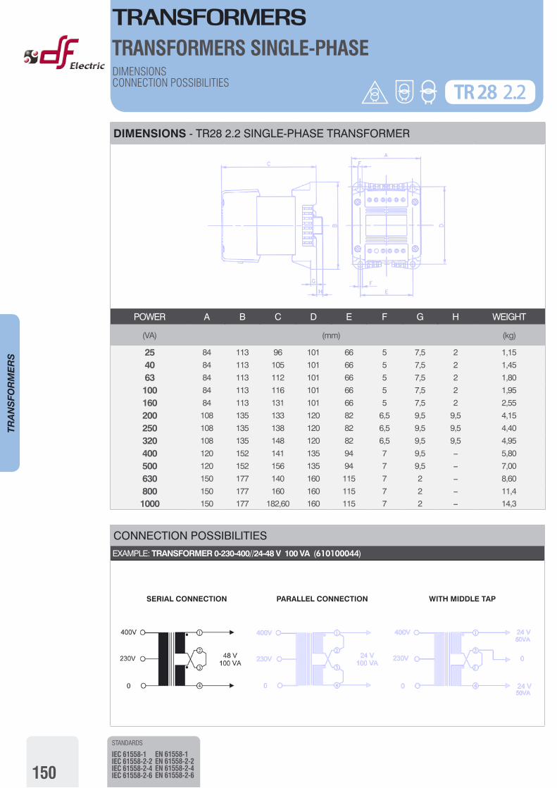
DIMENSIONS - TR28 2.2 SINGLE-PHASE TRANSFORMER
POWER A B C D E F G H WEIGHT
(VA) (mm) (kg)
25 84 113 96 101 66 5 7,5 2 1,15
40 84 113 105 101 66 5 7,5 2 1,45
63 84 113 112 101 66 5 7,5 2 1,80
100 84 113 116 101 66 5 7,5 2 1,95
160 84 113 131 101 66 5 7,5 2 2,55
200 108 135 133 120 82 6,5 9,5 9,5 4,15
250 108 135 138 120 82 6,5 9,5 9,5 4,40
320 108 135 148 120 82 6,5 9,5 9,5 4,95
400 120 152 141 135 94 7 9,5 – 5,80
500 120 152 156 135 94 7 9,5 – 7,00
630 150 177 140 160 115 7 2 – 8,60
800 150 177 160 160 115 7 2 – 11,4
1000 150 177 182,60 160 115 7 2 – 14,3
CONNECTION POSSIBILITIES EXAMPLE: TRANSFORMER 0-230-400//24-48 V 100 VA (610100044)
SERIAL CONNECTION PARALLEL CONNECTION WITH MIDDLE TAP
TRANSFORMERSTRANSFORMERS SINGLE-PHASE
151
TRANSFO
RMERS
DIMENSIONSCONNECTION POSSIBILITIES TR 28 5.2
STANDARDS
IEC 61558-1IEC 61558-2-2IEC 61558-2-4IEC 61558-2-6
EN 61558-1EN 61558-2-2EN 61558-2-4EN 61558-2-6
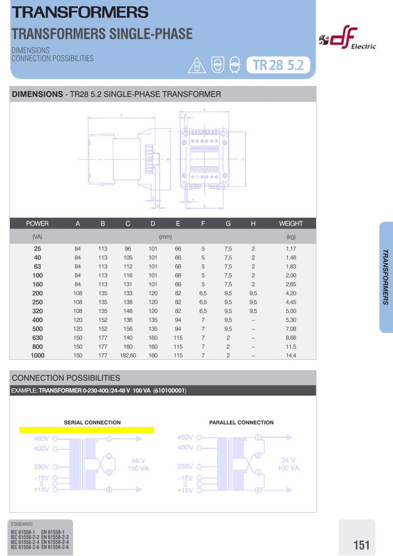
DIMENSIONS - TR28 5.2 SINGLE-PHASE TRANSFORMER
POWER A B C D E F G H WEIGHT
(VA) (mm) (kg)
25 84 113 96 101 66 5 7,5 2 1,17
40 84 113 105 101 66 5 7,5 2 1,48
63 84 113 112 101 66 5 7,5 2 1,83
100 84 113 116 101 66 5 7,5 2 2,00
160 84 113 131 101 66 5 7,5 2 2,65
200 108 135 133 120 82 6,5 9,5 9,5 4,20
250 108 135 138 120 82 6,5 9,5 9,5 4,45
320 108 135 148 120 82 6,5 9,5 9,5 5,00
400 120 152 136 135 94 7 9,5 – 5,30
500 120 152 156 135 94 7 9,5 – 7,08
630 150 177 140 160 115 7 2 – 8,68
800 150 177 160 160 115 7 2 – 11,5
1000 150 177 182,60 160 115 7 2 – 14,4
CONNECTION POSSIBILITIES EXAMPLE: TRANSFORMER 0-230-400//24-48 V 100 VA (610100001)
SERIAL CONNECTION PARALLEL CONNECTION
TRANSFORMERS
152
TRANSFO
RMERS
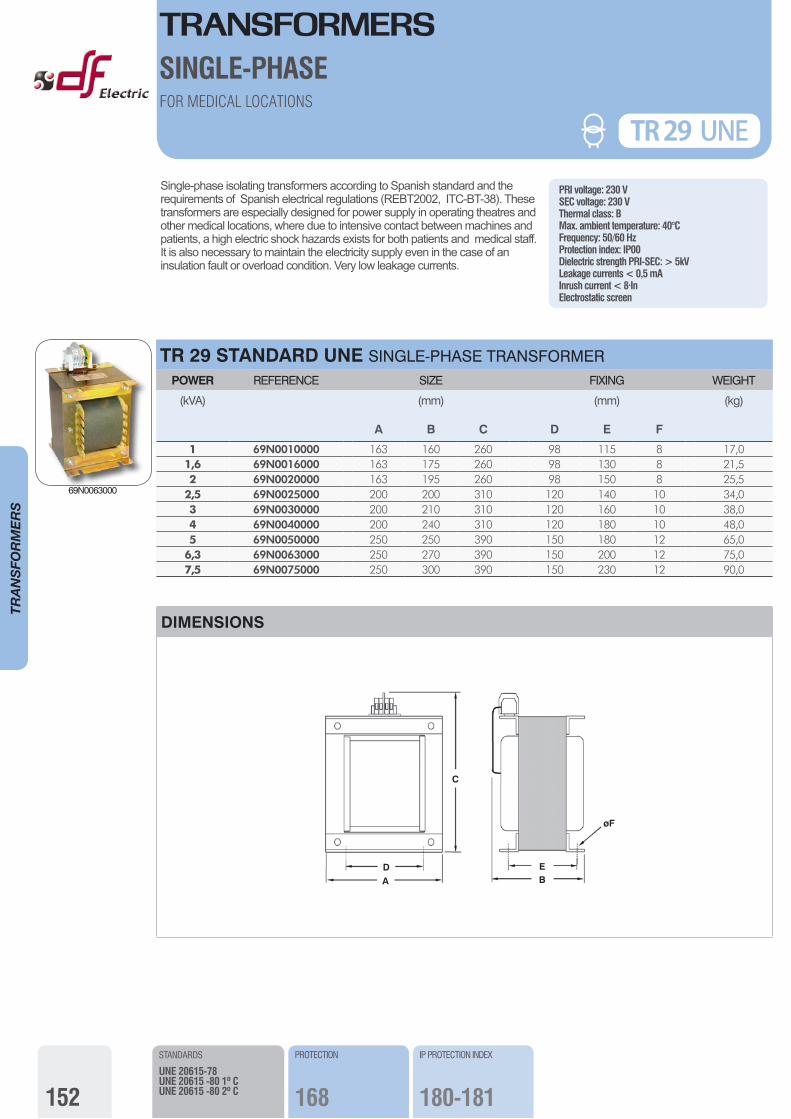
TR 29 STANDARD UNE SINGLE-PHASE TRANSFORMER POWER REFERENCE SIZE FIXING WEIGHT
(kVA)
A
(mm)
B C D
(mm)
E F
(kg)
1 69N0010000 163 160 260 98 115 8 17,01,6 69N0016000 163 175 260 98 130 8 21,52 69N0020000 163 195 260 98 150 8 25,5
2,5 69N0025000 200 200 310 120 140 10 34,03 69N0030000 200 210 310 120 160 10 38,04 69N0040000 200 240 310 120 180 10 48,05 69N0050000 250 250 390 150 180 12 65,0
6,3 69N0063000 250 270 390 150 200 12 75,07,5 69N0075000 250 300 390 150 230 12 90,0
PRI voltage: 230 VSEC voltage: 230 VThermal class: BMax. ambient temperature: 40°CFrequency: 50/60 HzProtection index: IP00Dielectric strength PRI-SEC: > 5kVLeakage currents < 0,5 mAInrush current < 8·InElectrostatic screen
Single-phase isolating transformers according to Spanish standard and the requirements of Spanish electrical regulations (REBT2002, ITC-BT-38). These transformers are especially designed for power supply in operating theatres and other medical locations, where due to intensive contact between machines and patients, a high electric shock hazards exists for both patients and medical staff. It is also necessary to maintain the electricity supply even in the case of an insulation fault or overload condition. Very low leakage currents.
TR 29 UNEFOR MEDICAL LOCATIONS
STANDARDS
UNE 20615-78UNE 20615 -80 1º CUNE 20615 -80 2º C
IP PROTECTION INDEX
180-181
PROTECTION
168
F
DIMENSIONS
DA
C
E
øF
B
SINGLE-PHASE
69N0063000
TRANSFORMERS
153
TRANSFO
RMERS
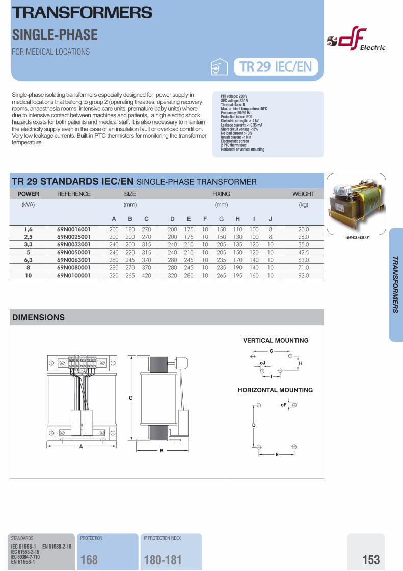
Single-phase isolating transformers especially designed for power supply in medical locations that belong to group 2 (operating theatres, operating recovery rooms, anaesthesia rooms, intensive care units, premature baby units) where due to intensive contact between machines and patients, a high electric shock hazards exists for both patients and medical staff. It is also necessary to maintain the electricity supply even in the case of an insulation fault or overload condition.Very low leakage currents. Built-in PTC thermistors for monitoring the transformer temperature.
PRI voltage: 230 VSEC voltage: 230 VThermal class: BMax. ambient temperature: 40°CFrequency: 50/60 HzProtection index: IP00Dielectric strength: > 4 kVLeakage currents < 0,35 mAShort circuit voltage <3%No load current > 3%Inrush current < 8·InElectrostatic screen2 PTC thermistorsHorizontal or vertical mounting
TR 29 STANDARDS IEC/EN SINGLE-PHASE TRANSFORMER POWER REFERENCE SIZE FIXING WEIGHT
(kVA)
A
(mm)
B C D E F
(mm)
G H I J
(kg)
1,6 69N0016001 200 180 270 200 175 10 150 110 100 8 20,02,5 69N0025001 200 200 270 200 175 10 150 130 100 8 26,03,3 69N0033001 240 200 315 240 210 10 205 135 120 10 35,05 69N0050001 240 220 315 240 210 10 205 150 120 10 42,5
6,3 69N0063001 280 245 370 280 245 10 235 170 140 10 63,08 69N0080001 280 270 370 280 245 10 235 190 140 10 71,010 69N0100001 320 265 420 320 280 10 265 195 160 10 93,0
FOR MEDICAL LOCATIONS
TR 29 IEC/EN
STANDARDS
IEC 61558-1IEC 61558-2-15IEC 60364-7-710EN 61558-1
EN 61588-2-15
PROTECTION
168
IP PROTECTION INDEX
180-181
DIMENSIONS
A
C
B
VERTICAL MOUNTING
HORIZONTAL MOUNTING
G
H
I
øJ
D
øF
E
SINGLE-PHASE
69N0063001
TRANSFORMERS
154
TRANSFO
RMERS
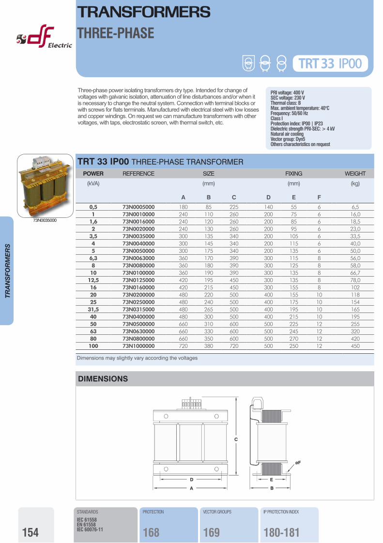
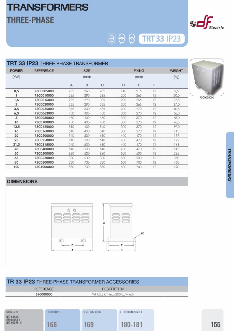
Three-phase power isolating transformers dry type. Intended for change of voltages with galvanic isolation, attenuation of line disturbances and/or when it is necessary to change the neutral system. Connection with terminal blocks or with screws for flats terminals. Manufactured with electrical steel with low losses and copper windings. On request we can manufacture transformers with other voltages, with taps, electrostatic screen, with thermal switch, etc.
PRI voltage: 400 VSEC voltage: 230 VThermal class: BMax. ambient temperature: 40°CFrequency: 50/60 HzClass IProtection index: IP00 | IP23Dielectric strength PRI-SEC: > 4 kVNatural air coolingVector group: Dyn5 Others characteristics on request
Dimensions may slightly vary according the voltages
TRT 33 IP00 THREE-PHASE TRANSFORMER POWER REFERENCE SIZE FIXING WEIGHT
(kVA)
A
(mm)
B C D
(mm)
E F
(kg)
0,5 73N0005000 180 85 225 140 55 6 6,51 73N0010000 240 110 260 200 75 6 16,0
1,6 73N0016000 240 120 260 200 85 6 18,52 73N0020000 240 130 260 200 95 6 23,0
3,5 73N0035000 300 135 340 200 105 6 33,54 73N0040000 300 145 340 200 115 6 40,05 73N0050000 300 175 340 200 135 6 50,0
6,3 73N0063000 360 170 390 300 115 8 56,08 73N0080000 360 180 390 300 125 8 58,010 73N0100000 360 190 390 300 135 8 66,7
12,5 73N0125000 420 195 450 300 135 8 78,016 73N0160000 420 215 450 300 155 8 10220 73N0200000 480 220 500 400 155 10 11825 73N0250000 480 240 500 400 175 10 154
31,5 73N0315000 480 265 500 400 195 10 16540 73N0400000 480 300 500 400 215 10 19550 73N0500000 660 310 600 500 225 12 25563 73N0630000 660 330 600 500 245 12 32080 73N0800000 660 350 600 500 270 12 420100 73N1000000 720 380 720 500 250 12 450
TRT 33 IP00
THREE-PHASE
STANDARDS
IEC 61558EN 61558IEC 60076-11
DIMENSIONS
D
A
C
E
øF
B
VECTOR GROUPS
169
PROTECTION
168
IP PROTECTION INDEX
180-181
73N0035000
TRANSFORMERS
155
TRANSFO
RMERS
TRT 33 IP23 THREE-PHASE TRANSFORMER POWER REFERENCE SIZE FIXING WEIGHT
(kVA)
A
(mm)
B C D
(mm)
E F
(kg)
0,5 73C0005000 235 240 285 140 215 12 9,51 73C0010000 285 290 335 200 265 12 20,0
1,6 73C0016000 285 290 335 200 265 12 22,52 73C0020000 285 290 335 200 265 12 27,0
3,5 73C0035000 375 300 435 200 270 12 40,56,3 73C0063000 450 400 480 300 370 12 66,08 73C0080000 450 400 480 300 370 12 68,010 73C0100000 450 400 480 300 370 12 76,5
12,5 73C0125000 510 400 540 300 370 12 89,016 73C0160000 510 400 540 300 370 12 11320 73C0200000 540 500 610 400 470 12 13725 73C0250000 540 500 610 400 470 12 172
31,5 73C0315000 540 500 610 400 470 12 18440 73C0400000 540 500 610 400 470 12 21550 73C0500000 880 530 830 500 500 12 28563 73C0630000 880 530 830 500 500 12 35080 73C0800000 880 730 830 500 700 12 460100 73C1000000 880 730 830 500 700 12 490
THREE-PHASE
STANDARDS
IEC 61558EN 61558-1IEC 60076-11
TRT 33 IP23
DIMENSIONS
D
A
E
øF
C
B
VECTOR GROUPS
169
PROTECTION
168
IP PROTECTION INDEX
180-181
TR 33 IP23 THREE-PHASE TRANSFORMER ACCESSORIESREFERENCE DESCRIPTION690000005 WHEELS KIT (max 200 kg/wheel)
73C0035000
TRANSFORMERS
156
TRANSFO
RMERS
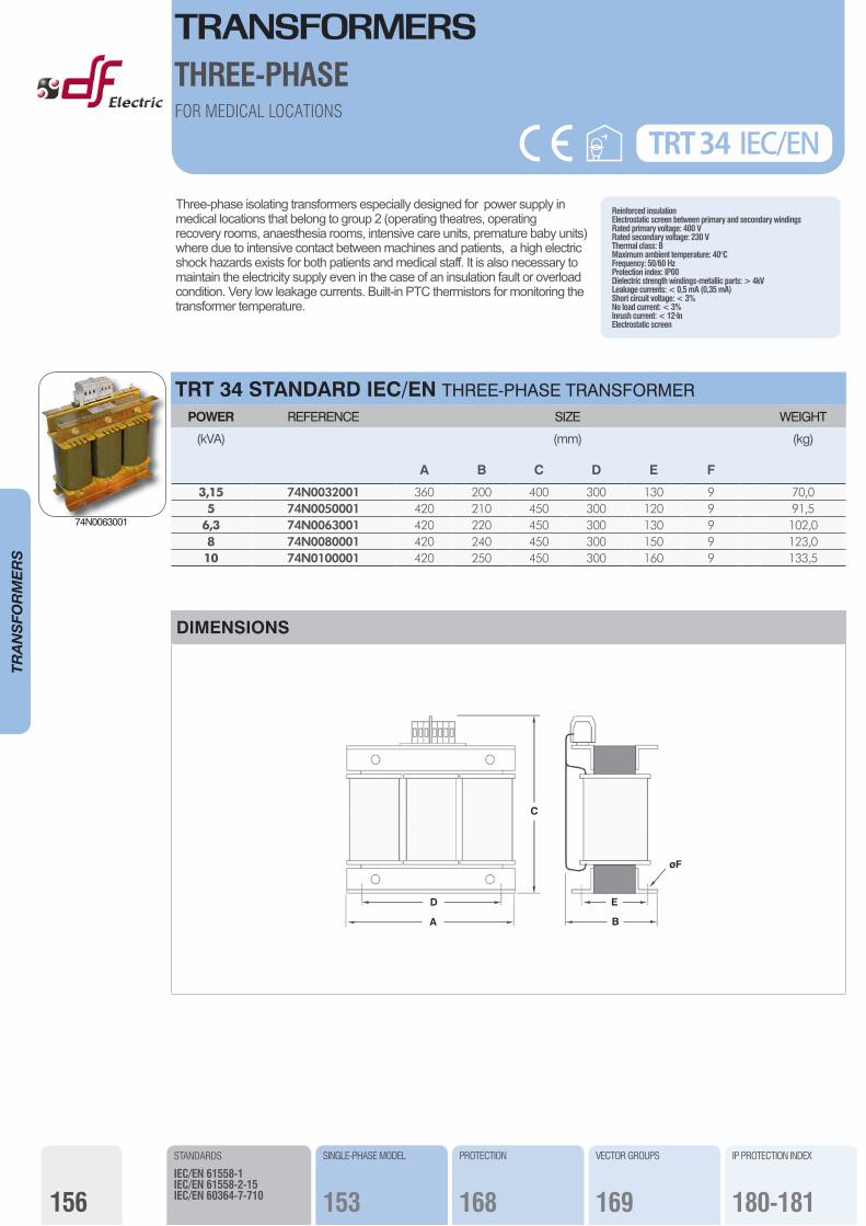
Three-phase isolating transformers especially designed for power supply in medical locations that belong to group 2 (operating theatres, operating recovery rooms, anaesthesia rooms, intensive care units, premature baby units) where due to intensive contact between machines and patients, a high electric shock hazards exists for both patients and medical staff. It is also necessary to maintain the electricity supply even in the case of an insulation fault or overload condition. Very low leakage currents. Built-in PTC thermistors for monitoring the transformer temperature.
Reinforced insulationElectrostatic screen between primary and secondary windingsRated primary voltage: 400 VRated secondary voltage: 230 VThermal class: BMaximum ambient temperature: 40°CFrequency: 50/60 HzProtection index: IP00Dielectric strength windings-metallic parts: > 4kVLeakage currents: < 0,5 mA (0,35 mA)Short circuit voltage: < 3%No load current: < 3%Inrush current: < 12·InElectrostatic screen
TRT 34 STANDARD IEC/EN THREE-PHASE TRANSFORMER POWER REFERENCE SIZE WEIGHT
(kVA) (mm) (kg)
A B C D E F
3,15 74N0032001 360 200 400 300 130 9 70,05 74N0050001 420 210 450 300 120 9 91,5
6,3 74N0063001 420 220 450 300 130 9 102,08 74N0080001 420 240 450 300 150 9 123,010 74N0100001 420 250 450 300 160 9 133,5
TRT 34 IEC/ENFOR MEDICAL LOCATIONS
THREE-PHASE
STANDARDS
IEC/EN 61558-1IEC/EN 61558-2-15IEC/EN 60364-7-710
DIMENSIONS
D
A
C
E
øF
B
74N0063001
PROTECTION
168
SINGLE-PHASE MODEL
153
VECTOR GROUPS
169
IP PROTECTION INDEX
180-181
TRANSFORMERS
157
TRANSFO
RMERS
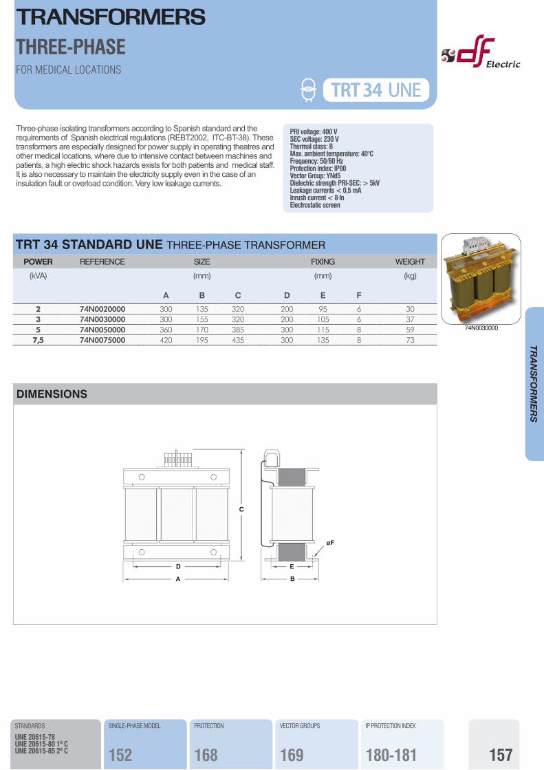
PRI voltage: 400 VSEC voltage: 230 VThermal class: BMax. ambient temperature: 40°CFrequency: 50/60 HzProtection index: IP00Vector Group: YNd5Dielectric strength PRI-SEC: > 5kVLeakage currents < 0,5 mAInrush current < 8·InElectrostatic screen
Three-phase isolating transformers according to Spanish standard and the requirements of Spanish electrical regulations (REBT2002, ITC-BT-38). These transformers are especially designed for power supply in operating theatres and other medical locations, where due to intensive contact between machines and patients, a high electric shock hazards exists for both patients and medical staff. It is also necessary to maintain the electricity supply even in the case of an insulation fault or overload condition. Very low leakage currents.
TRT 34 STANDARD UNE THREE-PHASE TRANSFORMER POWER REFERENCE SIZE FIXING WEIGHT
(kVA)
A
(mm)
B C D
(mm)
E F
(kg)
2 74N0020000 300 135 320 200 95 6 303 74N0030000 300 155 320 200 105 6 375 74N0050000 360 170 385 300 115 8 59
7,5 74N0075000 420 195 435 300 135 8 73
TRT 34
STANDARDS
UNE 20615-78UNE 20615-80 1º CUNE 20615-85 2º C
FOR MEDICAL LOCATIONS
THREE-PHASE
DIMENSIONS
D
A
C
E
øF
B
TRT 34 UNE
74N0030000
PROTECTION
168
SINGLE-PHASE MODEL
152
VECTOR GROUPS
169
IP PROTECTION INDEX
180-181
158
TRANSFO
RMERS
TR 24 SINGLE-PHASE AUTOTRANSFORMER POWER REFERENCE SIZE FIXING WEIGHT
(VA)
A
(mm)
B C D
(mm)
E F
(kg)
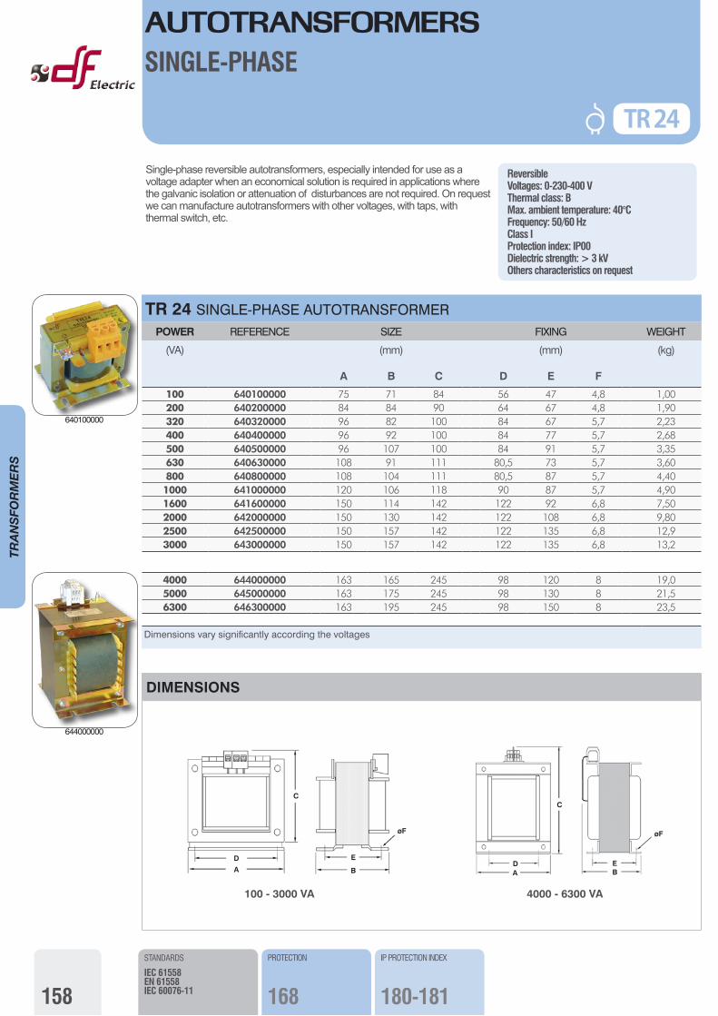
100 640100000 75 71 84 56 47 4,8 1,00200 640200000 84 84 90 64 67 4,8 1,90320 640320000 96 82 100 84 67 5,7 2,23400 640400000 96 92 100 84 77 5,7 2,68500 640500000 96 107 100 84 91 5,7 3,35630 640630000 108 91 111 80,5 73 5,7 3,60800 640800000 108 104 111 80,5 87 5,7 4,401000 641000000 120 106 118 90 87 5,7 4,901600 641600000 150 114 142 122 92 6,8 7,502000 642000000 150 130 142 122 108 6,8 9,802500 642500000 150 157 142 122 135 6,8 12,93000 643000000 150 157 142 122 135 6,8 13,2
AUTOTRANSFORMERSSINGLE-PHASE
Single-phase reversible autotransformers, especially intended for use as a voltage adapter when an economical solution is required in applications where the galvanic isolation or attenuation of disturbances are not required. On request we can manufacture autotransformers with other voltages, with taps, with thermal switch, etc.
ReversibleVoltages: 0-230-400 VThermal class: BMax. ambient temperature: 40°CFrequency: 50/60 HzClass IProtection index: IP00Dielectric strength: > 3 kVOthers characteristics on request
TR 24
4000 644000000 163 165 245 98 120 8 19,05000 645000000 163 175 245 98 130 8 21,56300 646300000 163 195 245 98 150 8 23,5
Dimensions vary significantly according the voltages
STANDARDS
IEC 61558EN 61558IEC 60076-11
PROTECTION
168
DIMENSIONS
D
A
C
E
øF
B
100 - 3000 VA
DA
C
E
øF
B
4000 - 6300 VA
IP PROTECTION INDEX
180-181
640100000
644000000
159
TRANSFO
RMERS
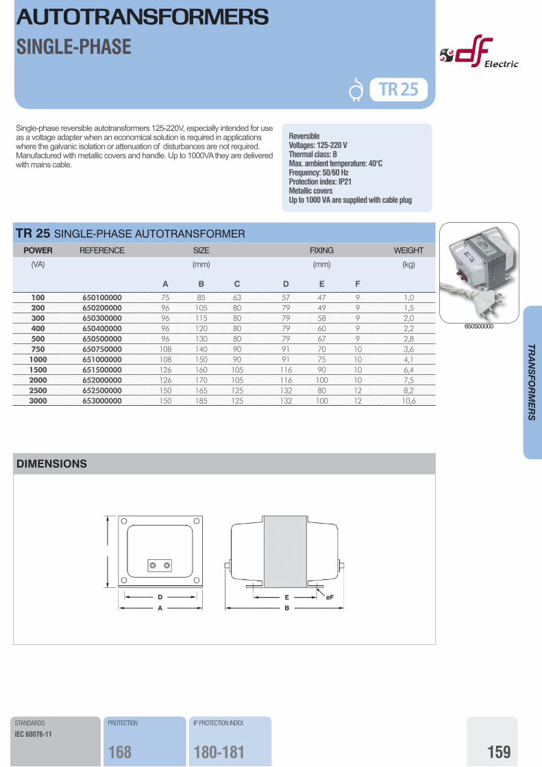
ReversibleVoltages: 125-220 VThermal class: BMax. ambient temperature: 40°CFrequency: 50/60 HzProtection index: IP21Metallic coversUp to 1000 VA are supplied with cable plug
Single-phase reversible autotransformers 125-220V, especially intended for use as a voltage adapter when an economical solution is required in applications where the galvanic isolation or attenuation of disturbances are not required.Manufactured with metallic covers and handle. Up to 1000VA they are delivered with mains cable.
TR 25 SINGLE-PHASE AUTOTRANSFORMER POWER REFERENCE SIZE FIXING WEIGHT
(VA)
A
(mm)
B C D
(mm)
E F
(kg)
100 650100000 75 85 63 57 47 9 1,0200 650200000 96 105 80 79 49 9 1,5300 650300000 96 115 80 79 58 9 2,0400 650400000 96 120 80 79 60 9 2,2500 650500000 96 130 80 79 67 9 2,8750 650750000 108 140 90 91 70 10 3,61000 651000000 108 150 90 91 75 10 4,11500 651500000 126 160 105 116 90 10 6,42000 652000000 126 170 105 116 100 10 7,52500 652500000 150 165 125 132 80 12 8,23000 653000000 150 185 125 132 100 12 10,6
AUTOTRANSFORMERS
TR 25
SINGLE-PHASE
STANDARDS
IEC 60076-11
DIMENSIONS
D
A
E øF
B
PROTECTION
168
IP PROTECTION INDEX
180-181
650500000

160
TRANSFO
RMERS
Three-phase reversible autotransformers, dry type, intended for use as voltage adapter when an economical solution is required in applications where the galvanic isolation or attenuation of disturbances are not required. The main applications include the voltage adaptation in motors, pumps, machines, air conditioning equipment. Connection with terminal blocks or with screws for flats terminals. Manufactured with electrical steel with low losses and copper windings.On request we can manufacture autotransformers with other voltages, with taps, with thermal switch, etc.
ReversibleCopper windingsVoltages: 230-400 VThermal class: BMax. ambient temperature: 40°CFrequency: 50/60 HzClass IProtection index: IP00Dielectric strength: > 3 kVNatural air coolingVector group: Yn0 (with neutral)Others characteristics on request
TRT 30 IP00 THREE-PHASE AUTOTRANSFORMER POWER REFERENCE SIZE FIXING WEIGHT
(kVA)
A
(mm)
B C D
(mm)
E F
(kg)
0,5 70N0005000 180 85 160 140 55 6 5,51 70N0010000 180 85 225 140 55 6 6,52 70N0020000 180 95 225 140 65 6 9,13 70N0030000 240 110 250 200 75 6 16,05 70N0050000 240 120 250 200 85 6 18,58 70N0080000 240 145 250 200 110 6 27,010 70N0100000 300 135 320 200 95 6 31,0
12,5 70N0125000 300 155 320 200 115 6 40,016 70N0160000 300 165 320 200 125 6 44,020 70N0200000 360 170 370 300 115 8 56,025 70N0250000 360 180 370 300 125 8 58,0
31,5 70N0315000 420 195 435 300 135 8 78,040 70N0400000 420 205 435 300 145 8 90,050 70N0500000 420 215 435 300 155 8 10263 70N0630000 480 240 500 400 175 10 15480 70N0800000 480 265 500 400 195 10 165100 70N1000000 480 300 500 400 215 10 195125 70N1250000 660 310 600 500 225 12 245160 70N1600000 660 330 600 500 245 12 305200 70N2000000 660 350 600 500 270 12 400
Dimensions vary significantly according the voltages
AUTOTRANSFORMERSTHREE-PHASE
TRT 30 IP00
STANDARDS
IEC 61558EN 61558IEC 60076-11
SELECTION GUIDE
166-167
PROTECTION
168
IP PROTECTION INDEX
180-181
DIMENSIONS
D
A
C
E
øF
B
70N0630000
161
TRANSFO
RMERS
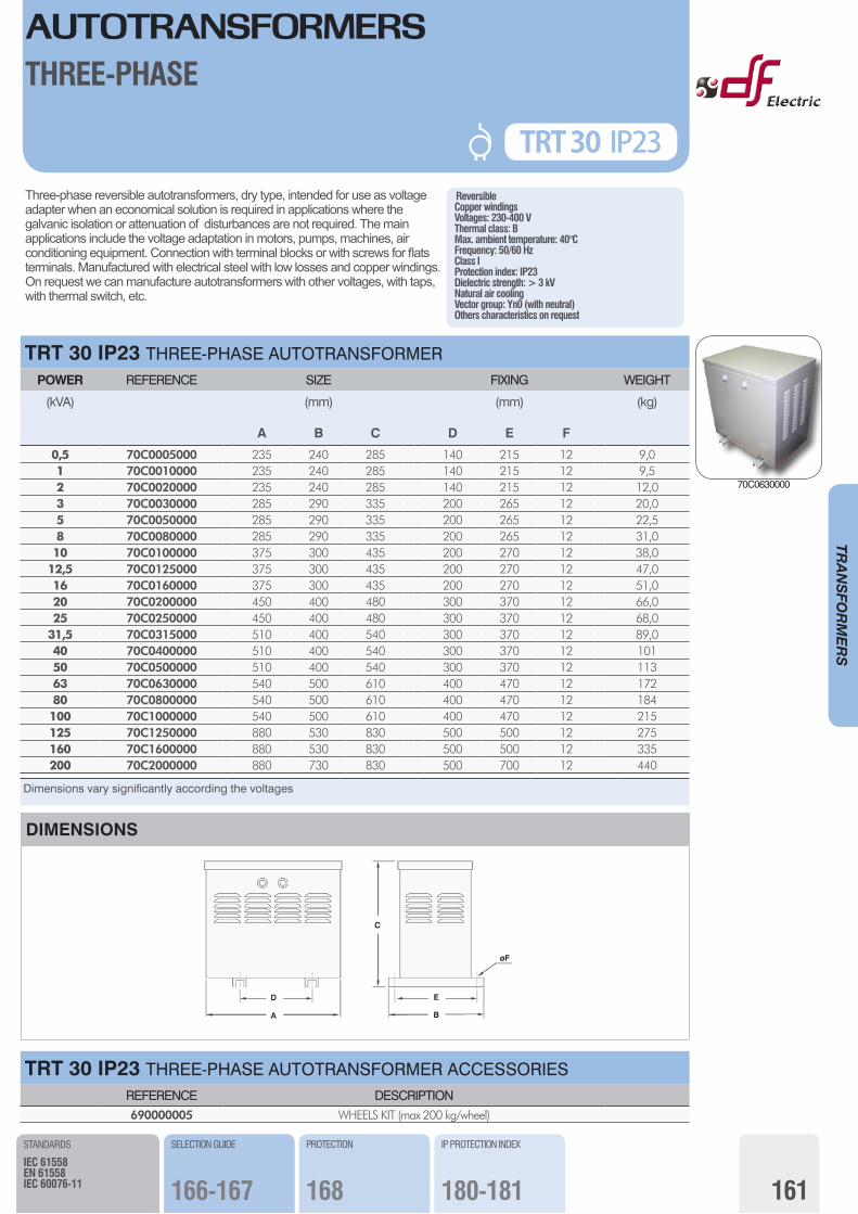
ReversibleCopper windingsVoltages: 230-400 VThermal class: BMax. ambient temperature: 40°CFrequency: 50/60 HzClass IProtection index: IP23Dielectric strength: > 3 kVNatural air coolingVector group: Yn0 (with neutral)Others characteristics on request
Three-phase reversible autotransformers, dry type, intended for use as voltage adapter when an economical solution is required in applications where the galvanic isolation or attenuation of disturbances are not required. The main applications include the voltage adaptation in motors, pumps, machines, air conditioning equipment. Connection with terminal blocks or with screws for flats terminals. Manufactured with electrical steel with low losses and copper windings.On request we can manufacture autotransformers with other voltages, with taps, with thermal switch, etc.
TRT 30 IP23 THREE-PHASE AUTOTRANSFORMER POWER REFERENCE SIZE FIXING WEIGHT
(kVA)
A
(mm)
B C D
(mm)
E F
(kg)
0,5 70C0005000 235 240 285 140 215 12 9,01 70C0010000 235 240 285 140 215 12 9,52 70C0020000 235 240 285 140 215 12 12,03 70C0030000 285 290 335 200 265 12 20,05 70C0050000 285 290 335 200 265 12 22,58 70C0080000 285 290 335 200 265 12 31,010 70C0100000 375 300 435 200 270 12 38,0
12,5 70C0125000 375 300 435 200 270 12 47,016 70C0160000 375 300 435 200 270 12 51,020 70C0200000 450 400 480 300 370 12 66,025 70C0250000 450 400 480 300 370 12 68,0
31,5 70C0315000 510 400 540 300 370 12 89,040 70C0400000 510 400 540 300 370 12 10150 70C0500000 510 400 540 300 370 12 11363 70C0630000 540 500 610 400 470 12 17280 70C0800000 540 500 610 400 470 12 184100 70C1000000 540 500 610 400 470 12 215125 70C1250000 880 530 830 500 500 12 275160 70C1600000 880 530 830 500 500 12 335200 70C2000000 880 730 830 500 700 12 440
Dimensions vary significantly according the voltages
AUTOTRANSFORMERSTHREE-PHASE
STANDARDS
IEC 61558EN 61558IEC 60076-11
SELECTION GUIDE
166-167
PROTECTION
168
IP PROTECTION INDEX
180-181
TRT 30 IP23
DIMENSIONS
D
A
E
øF
C
B
TRT 30 IP23 THREE-PHASE AUTOTRANSFORMER ACCESSORIESREFERENCE DESCRIPTION690000005 WHEELS KIT (max 200 kg/wheel)
70C0630000
162
TRANSFO
RMERS
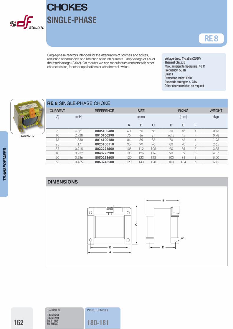
Single-phase reactors intended for the attenuation of notches and spikes, reduction of harmonics and limitation of inrush currents. Drop voltage of 4% of the rated voltage (230V). On request we can manufacture reactors with other characteristics, for other applications or with thermal switch.
Voltage drop: 4% at IN (230V)Thermal class: BMax. ambient temperature: 40°CFrequency: 50 HzClass IProtection index: IP00Dielectric strength: > 3 kVOther characteristics on request
RE 8 SINGLE-PHASE CHOKE CURRENT REFERENCE SIZE FIXING WEIGHT
(A) (mH)
A
(mm)
B C D
(mm)
E F
(kg)
6 4,881 8006100480 60 70 68 50 48 4 0,7310 2,928 8010100290 75 66 81 62,5 45 4 0,9816 1,830 8016100180 84 85 86 70 66 4 1,9825 1,171 8025100110 96 90 96 80 70 5 2,6532 0,915 8032291500 108 112 106 90 75 5 3,5640 0,732 8040273200 108 126 116 90 89 5 4,3750 0,586 8050258600 120 123 128 100 84 6 5,0063 0,465 8063246500 120 143 128 100 104 6 6,75
CHOKESSINGLE-PHASE
RE 8
STANDARDS
IEC 61558IEC 60289EN 61558EN 60289
IP PROTECTION INDEX
180-181
DIMENSIONS
D
A
E
øF
C
B
8025100110
163
TRANSFO
RMERS
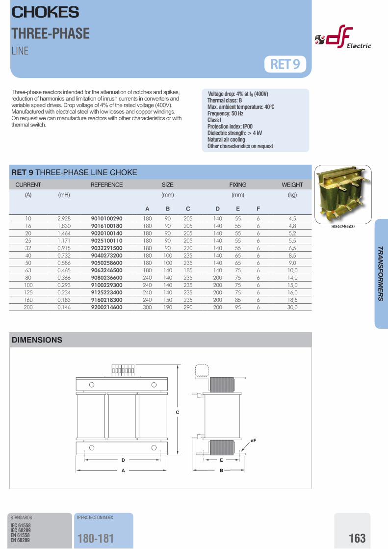
Three-phase reactors intended for the attenuation of notches and spikes, reduction of harmonics and limitation of inrush currents in converters and variable speed drives. Drop voltage of 4% of the rated voltage (400V).Manufactured with electrical steel with low losses and copper windings. On request we can manufacture reactors with other characteristics or with thermal switch.
Voltage drop: 4% at IN (400V)Thermal class: BMax. ambient temperature: 40°CFrequency: 50 HzClass IProtection index: IP00Dielectric strength: > 4 kVNatural air coolingOther characteristics on request
RET 9 THREE-PHASE LINE CHOKE CURRENT REFERENCE SIZE FIXING WEIGHT
(A) (mH)
A
(mm)
B C D
(mm)
E F
(kg)
10 2,928 9010100290 180 90 205 140 55 6 4,516 1,830 9016100180 180 90 205 140 55 6 4,820 1,464 9020100140 180 90 205 140 55 6 5,225 1,171 9025100110 180 90 205 140 55 6 5,532 0,915 9032291500 180 90 220 140 55 6 6,540 0,732 9040273200 180 100 235 140 65 6 8,550 0,586 9050258600 180 100 235 140 65 6 9,063 0,465 9063246500 180 140 185 140 75 6 10,080 0,366 9080236600 240 140 235 200 75 6 14,0100 0,293 9100229300 240 140 235 200 75 6 15,0125 0,234 9125223400 240 140 235 200 75 6 16,0160 0,183 9160218300 240 150 235 200 85 6 18,5200 0,146 9200214600 300 190 290 200 95 6 30,0
CHOKESTHREE-PHASELINE
RET 9
STANDARDS
IEC 61558IEC 60289EN 61558EN 60289
IP PROTECTION INDEX
180-181
DIMENSIONS
D
A
C
E
øF
B
9063246500
164
TRANSFO
RMERS
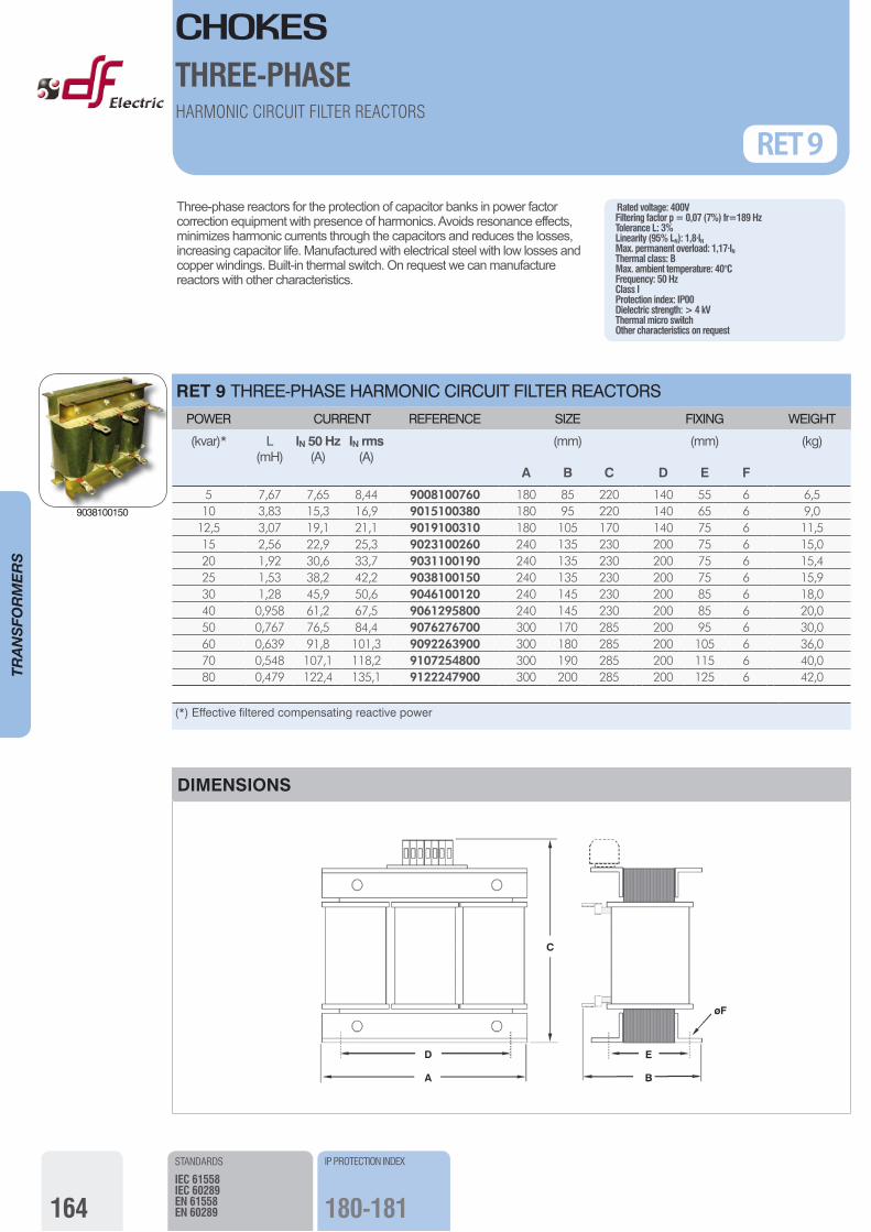
Three-phase reactors for the protection of capacitor banks in power factor correction equipment with presence of harmonics. Avoids resonance effects, minimizes harmonic currents through the capacitors and reduces the losses, increasing capacitor life. Manufactured with electrical steel with low losses and copper windings. Built-in thermal switch. On request we can manufacture reactors with other characteristics.
Rated voltage: 400VFiltering factor p = 0,07 (7%) fr=189 HzTolerance L: 3%Linearity (95% LN): 1,8·IN Max. permanent overload: 1,17·INThermal class: BMax. ambient temperature: 40°CFrequency: 50 HzClass IProtection index: IP00Dielectric strength: > 4 kVThermal micro switch Other characteristics on request
RET 9 THREE-PHASE HARMONIC CIRCUIT FILTER REACTORS POWER CURRENT REFERENCE SIZE FIXING WEIGHT
(kvar)* L(mH)
IN 50 Hz(A)
IN rms(A)
A
(mm)
B C D
(mm)
E F
(kg)
5 7,67 7,65 8,44 9008100760 180 85 220 140 55 6 6,510 3,83 15,3 16,9 9015100380 180 95 220 140 65 6 9,0
12,5 3,07 19,1 21,1 9019100310 180 105 170 140 75 6 11,515 2,56 22,9 25,3 9023100260 240 135 230 200 75 6 15,020 1,92 30,6 33,7 9031100190 240 135 230 200 75 6 15,425 1,53 38,2 42,2 9038100150 240 135 230 200 75 6 15,930 1,28 45,9 50,6 9046100120 240 145 230 200 85 6 18,040 0,958 61,2 67,5 9061295800 240 145 230 200 85 6 20,050 0,767 76,5 84,4 9076276700 300 170 285 200 95 6 30,060 0,639 91,8 101,3 9092263900 300 180 285 200 105 6 36,070 0,548 107,1 118,2 9107254800 300 190 285 200 115 6 40,080 0,479 122,4 135,1 9122247900 300 200 285 200 125 6 42,0
(*) Effective filtered compensating reactive power
CHOKESTHREE-PHASEHARMONIC CIRCUIT FILTER REACTORS
STANDARDS
IEC 61558IEC 60289EN 61558EN 60289
IP PROTECTION INDEX
180-181
RET 9
DIMENSIONS
D
A
C
E
øF
B
9038100150
TRANSFORMERS
165
TRANSFO
RMERS
TR21 and TR28 SELECTION GUIDE
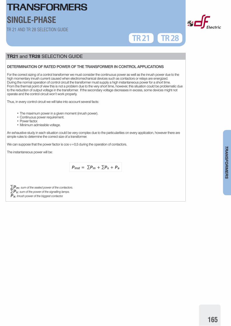
DETERMINATION OF RATED POWER OF THE TRANSFORMER IN CONTROL APPLICATIONS
For the correct sizing of a control transformer we must consider the continuous power as well as the inrush power due to the high momentary inrush current caused when electromechanical devices such as contactors or relays are energized.During the normal operation of control circuit the transformer must supply a high instantaneous power for a short time. From the thermal point of view this is not a problem due to the very short time, however, this situation could be problematic due to the reduction of output voltage in the transformer. If the secondary voltage decreases in excess, some devices might not operate and the control circuit won’t work properly.
Thus, in every control circuit we will take into account several facts:
• The maximum power in a given moment (inrush power).• Continuous power requirement.• Power factor.• Minimum admissible voltage.
An exhaustive study in each situation could be very complex due to the particularities on every application, however there are simple rules to determine the correct size of a transformer.
We can suppose that the power factor is cos ϕ=0,5 during the operation of contactors.
The instantaneous power will be:
Pinst = ∑Pm + ∑Ps + Pa
∑Pm: sum of the sealed power of the contactors. ∑Ps: sum of the power of the signalling lamps. Pa: Inrush power of the biggest contactor.
TR 28TR 21TR 21 AND TR 28 SELECTION GUIDE
SINGLE-PHASE
166
TRANSFO
RMERS
SELECTION GUIDE
DETERMINATION OF AUTO-TRANSFORMERS FOR MOTORS
When it is necessary to select an autotransformer for supply a electric motor or an equipment where the main charge is a motor, it is important to take into account the type of mechanic charge of the motor as well as the type of start, in order to consider the time and the peak currents that the autotransformer must withstand.For another hand we must bear in mind the frequency of the starts of the motor (number of starts per hour).
Basically we can consider three load types on the motor:
• Normal load.• Heavy load.• Soft starter or variable speed drive.
1. NORMAL LOAD
Direct start on line, star-delta or start with resistors/reactances with fast start and low inertia load on the motor.
Examples:
• Air conditioned. • Colds chambers or freezers.• Compressors.• Machine tools.
2. HEAVY LOAD
Applications where the motor has a load with high inertia what causes a very slow start.
Examples:
• Belt conveyor.• Fans.• Shaping machine.• Grinding machine.• Pump.• Rolling-mill train.
3. SOFT STARTER OR VARIABLE SPEED DRIVE.
The use of soft starters or variable speed drives can avoid the high starting current, however, the harmonics increase the losses in the autotransformers which cause elevation of temperature. This point must be take into account for the correct choosing of the rated power because an excessive temperature rise can reduce drastically the duration of the autotransformer.
TR T 30
AUTOTRANSFORMERSTHREE-PHASEREVERSIBLES - SELECTION GUIDE
167
TRANSFO
RMERS
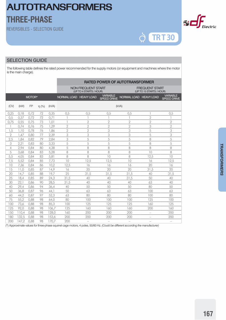
SELECTION GUIDE
The following table defines the rated power recommended for the supply motors (or equipment and machines where the motor is the main charge).
RATED POWER OF AUTOTRANSFORMER
NON FREQUENT START(UP TO 4 STARTS / HOUR)
FREQUENT START(UP TO 15 STARTS / HOUR)
MOTOR* NORMAL LOAD HEAVY LOAD VARIABLE SPEED DRIVE NORMAL LOAD HEAVY LOAD VARIABLE
SPEED DRIVE
(CV) (kW) FP η (%) (kVA) (kVA)
0,25 0,18 0,72 72 0,35 0,5 0,5 0,5 0,5 1 0,50,5 0,37 0,72 72 0,71 1 1 1 1 2 10,75 0,55 0,75 73 1,01 1 2 2 2 2 2
1 0,74 0,76 75 1,29 2 2 2 2 3 21,5 1,10 0,78 76 1,86 2 2 3 3 5 32 1,47 0,80 77 2,39 3 3 3 3 5 3
2,5 1,84 0,82 79 2,84 3 5 5 5 8 53 2,21 0,83 80 3,33 5 5 5 5 8 54 2,94 0,84 80 4,38 5 8 8 8 8 85 3,68 0,84 83 5,28 8 8 8 8 10 8
5,5 4,05 0,84 83 5,81 8 8 10 8 12,5 107,5 5,52 0,84 85 7,73 10 12,5 12,5 10 16 12,510 7,36 0,84 86 10,2 12,5 16 16 16 20 1615 11,0 0,85 87 14,9 16 20 20 20 31,5 2020 14,7 0,85 88 19,7 25 31,5 31,5 31,5 40 31,525 18,4 0,85 89 24,3 31,5 40 40 31,5 50 4030 22,1 0,86 90 28,5 31,5 40 40 40 63 4040 29,4 0,86 94 36,4 40 50 50 50 80 5050 36,8 0,87 96 44,1 50 63 63 63 100 6360 44,2 0,87 97 52,3 63 80 80 80 100 8075 55,2 0,88 98 64,0 80 100 100 100 125 100100 73,6 0,88 98 85,3 100 125 125 125 160 125125 92,0 0,88 98 106,7 125 160 160 160 200 160150 110,4 0,88 98 128,0 160 200 200 200 – 200180 132,5 0,88 98 153,6 200 200 200 200 – 200200 147,2 0,88 98 170,7 200 – – – – –
(*) Approximate values for three-phase squirrel cage motors, 4 poles, 50/60 Hz. (Could be different according the manufacturer)
AUTOTRANSFORMERSTHREE-PHASEREVERSIBLES - SELECTION GUIDE
TR T 30
168
TRANSFO
RMERS
PROTECTION OF TRANSFORMERS AND AUTOTRANSFORMERS
The transformers and autotransformers (and their lines) must be protected against overloads and/or short-circuits that they can be submitted in use, and could causes dangerous situations for persons, animals or installations.This protection are also a requirement of the standards and the national regulations about electrical installations.
Due to the high inrush current (about 25·In) it is very difficult to get an optimal protection in the primary side. If we select the rated current of fuses according to the primary rated current, the inrush current will melt the fuses. On the other hand, if the fuses are overrating for withstand the inrush, the transformer won’t have a good protection against overloads.
For this reason we recommend to protect transformers and autotransformers on the secondary side (output).The most adequate way to protect this devices (and their lines) is to include on the output side a device protection capable to interrupt overloads as well as short circuits. For the other hand the input line must be protected against short circuit.
As a general rule the criteria to select the ratings of protection devices are the following:
PROTECTION ON THE OUTPUT SIDE (LOAD)
In this part can appear overloads (if the user try to obtain a power higher than the rated power) as well as short circuits.
In order to achieve a good protection, the device (fuse link, circuit breaker or similar) must be capable to interrupt all range of currents (overloads and short circuits) and must have a rated current equal or lower than the output rated current of the autotransformer.
PROTECTION ON THE INPUT SIDE (SUPPLY LINE) In this part there is no risk of overload because if the output protection has been correctly selected, it will operate if appear an overload at the output side and the load will be disconnected of the autotransformer.
For this reason we only must protect the input line of autotransformer against short circuits in the line, in the autotransformer connections or inside the windings in a hypothetical failure of the insulations.
When the transformer is energized, it can demand a high momentary current (can be about 25 times the rated current) with a duration of a few milliseconds, that decrease very quickly until reach the rated value.
This factors should be take into account to choose the protection in order to avoid the fusing of the fuses or the not desired operation of the circuit breakers:
• Miniature fuses 5x20 ó 6x32 time-lag (slow) according to IEC/EN60127:In fuse link ≥ 3·In transformer
• Fuse links aM type according to IEC/EN60269:In fuse link ≥ 1,8·In transformer
• Fuse links gG type according to IEC/EN60269:In fuse link ≥ 3·In transformer
PROTECTION
TRANSFORMERSAUTOTRANSFORMERS

TRANSFORMERS
169
TRANSFO
RMERS
VECTOR GROUPS FOR THREE-PHASE TRANSFORMERSVECTOR GROUP
PHASE ANGLE GREATER VOLTAGE SMALLER VOLTAGE VECTOR
GROUPPHASE ANGLE GREATER VOLTAGE SMALLER VOLTAGE
Dd0 0(0°) Dd6 6
(180°)
Yy0 0(0°) Yy6 6
(180°)
Dy5 5(150°) Dy11 11
(330°)
Yd5 5(150°) Yd11 11
(330°)
D g DELTA CONNECTIONY g STAR (WYE) CONNECTION
• Capital letters (D, Y, N) are associated to the winding with the greater voltage and small letters (d, and, n) with the smaller voltage.
• If the neutral point of star connection winding is accessible (can be connected) is indicated by the letter N: YN or yn.
1U 1V 1W 2U 2V 2W 1U 1V 1W 2U 2V 2W
1U 1V 1W 2U 2V 2W 1U 1V 1W 2U 2V 2W
1U 1V 1W 2U 2V 2W 1U 1V 1W 2U 2V 2W
1U 1V 1W 2U 2V 2W 1U 1V 1W 2U 2V 2W
THREE-PHASEVECTOR GROUPS