transformations and compound transformationsmath.buffalostate.edu/~it/workshop2006/g17.pdfdynamic...
TRANSCRIPT
Summer 2006 I2T2 Geometry Page 79
G17 – Sketchpad Transformations
Transformations and Compound Transformations [Key Idea 1, 3, 4, 5, 7] Exploration #1
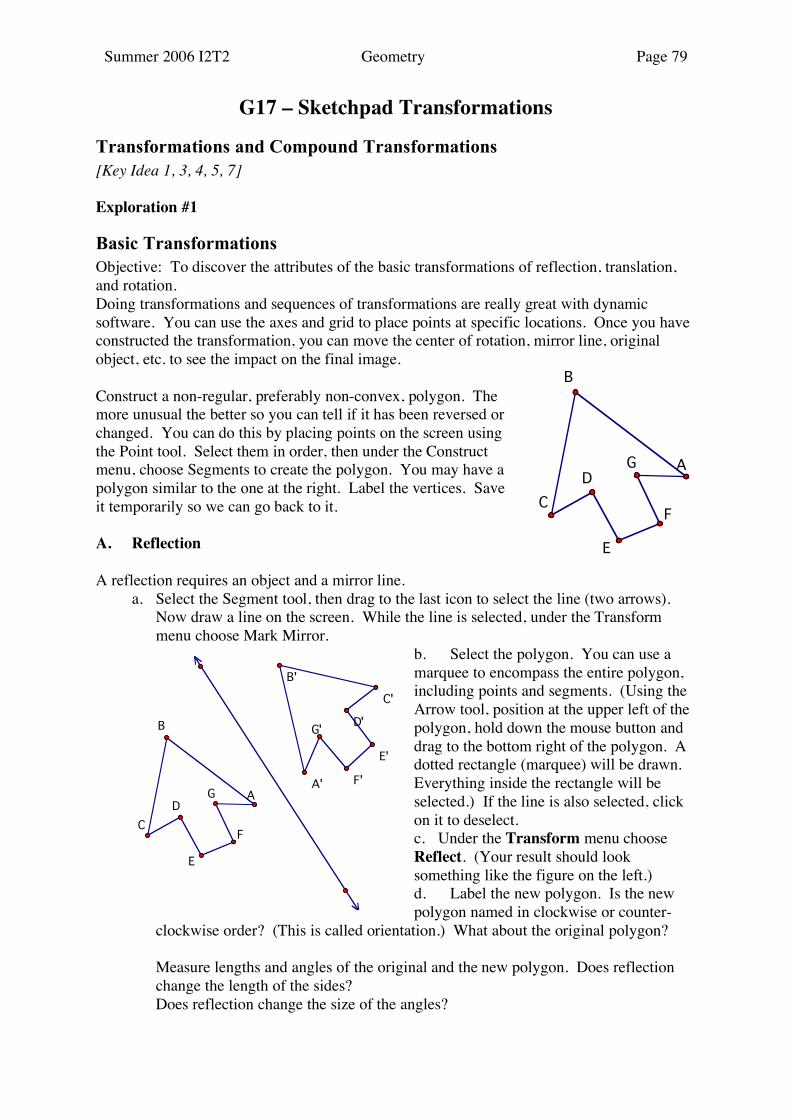
Basic Transformations Objective: To discover the attributes of the basic transformations of reflection, translation, and rotation. Doing transformations and sequences of transformations are really great with dynamic software. You can use the axes and grid to place points at specific locations. Once you have constructed the transformation, you can move the center of rotation, mirror line, original object, etc. to see the impact on the final image. Construct a non-regular, preferably non-convex, polygon. The more unusual the better so you can tell if it has been reversed or changed. You can do this by placing points on the screen using the Point tool. Select them in order, then under the Construct menu, choose Segments to create the polygon. You may have a polygon similar to the one at the right. Label the vertices. Save it temporarily so we can go back to it. A. Reflection A reflection requires an object and a mirror line. a. Select the Segment tool, then drag to the last icon to select the line (two arrows).
Now draw a line on the screen. While the line is selected, under the Transform menu choose Mark Mirror.
b. Select the polygon. You can use a marquee to encompass the entire polygon, including points and segments. (Using the Arrow tool, position at the upper left of the polygon, hold down the mouse button and drag to the bottom right of the polygon. A dotted rectangle (marquee) will be drawn. Everything inside the rectangle will be selected.) If the line is also selected, click on it to deselect. c. Under the Transform menu choose Reflect. (Your result should look something like the figure on the left.) d. Label the new polygon. Is the new polygon named in clockwise or counter-
clockwise order? (This is called orientation.) What about the original polygon? Measure lengths and angles of the original and the new polygon. Does reflection
change the length of the sides? Does reflection change the size of the angles?
A
B
C
D
E
F
G
A'
B'
C'
D'
E'
F'
G'
A
B
C
D
E
F
G

Summer 2006 I2T2 Geometry Page 80
e. Check your observations by moving points on the original polygon and moving the
line. Under reflection, circle what remains unchanged: lengths angle measure orientation B. Translation
For a translation, you need an object and a vector or change in x and y. For this example, we will use a line segment where the order in which the endpoints are named indicates the direction and the length. a. Get rid of everything except the original polygon by reopening the file with your
saved polygon. (Or under the Edit menu choose Undo... until you are back to your original polygon.)
b. Change the Line tool back to a segment and draw a segment. Choose the endpoints of the segment. Under the Transform menu, choose Mark Vector.
c. Select the polygon. d. Under the Transform menu, choose
Translate. A dialog box will appear for "Translation Vector" and the button next to Marked should be selected. Choose Translate.
e. Label the new polygon. Is the new polygon named in clockwise or counter-clockwise order? What about the original polygon?
Does translation change the length of
the sides? Does translation change the size of the angles? f. Check your observations by moving points on the original polygon, changing the
line segment. Under translation, circle what remains unchanged: lengths angle measure orientation
Translation by Δx, Δy g. Undo until you are back to your original shape. h. Select your shape, then go to the Transform menu and choose Translate. This
time from the dialog menu select Rectangular. i. Now enter a horizontal distance, such as 2, and a vertical distance, such as –7. Confirm your observations from (f) above. j. Notice that the third choice is polar, where you would enter a distance and angle, or
mark a distance and an angle to be used. Try it. C. Rotation For a rotation you need an object, a point for the
center of the rotation, and an angle of rotation.
a. Return to the original polygon. b. Select point A on the polygon. Under
Transform choose Mark Center.
G'
F'
E'
D'
C'
B'
A'A
B
C
D
E
F
G
G'F'
E'D'
C'
B'
A
B
C
D
E
F
G
Summer 2006 I2T2 Geometry Page 81
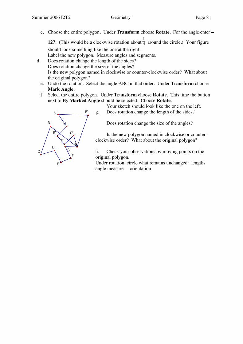
c. Choose the entire polygon. Under Transform choose Rotate. For the angle enter –
127. (This would be a clockwise rotation about 13 around the circle.) Your figure
should look something like the one at the right. Label the new polygon. Measure angles and segments. d. Does rotation change the length of the sides? Does rotation change the size of the angles? Is the new polygon named in clockwise or counter-clockwise order? What about
the original polygon? e. Undo the rotation. Select the angle ABC in that order. Under Transform choose
Mark Angle. f. Select the entire polygon. Under Transform choose Rotate. This time the button
next to By Marked Angle should be selected. Choose Rotate. Your sketch should look like the one on the left. g. Does rotation change the length of the sides? Does rotation change the size of the angles? Is the new polygon named in clockwise or counter-clockwise order? What about the original polygon? h. Check your observations by moving points on the original polygon. Under rotation, circle what remains unchanged: lengths angle measure orientation
G'
F'
E'
D'
C' B'
A
B
C
D
E
F
G

Summer 2006 I2T2 Geometry Page 82
Exploration #2
Compound Transformations Dynamic software is especially nice for investigating compound transformations. First construct a non-convex polygon. (I like to use something that looks like an F or an arrowhead.) What happens when you apply two transformations to this polygon? Is there a single transformation that will have the same effect? Will the result be the same if you reverse the order of the transformations? A. Reflection in two parallel lines: a. Construct your polygon, or use the one from the previous Exploration. Construct a
line. Construct a point, not on the line, and construct a line parallel to the first line through that point.
b. Label the polygon and the two parallel lines. c. Reflect the polygon in the first parallel line (j), then in the second parallel line (k).
(See sketch below.) Compare the original polygon and the final polygon in regards to size and orientation.
Reflection in two parallel lines is the same as a _______________________. d. Find a single translation that, when applied to the original polygon, will have the
same result as two reflections in parallel lines. Check this by testing.
A reflection in 2 parallel lines is the same as a translation in the direction __________ ______________________ of length e. Now undo the previous reflections. Select the original polygon and reflect it in the
parallel lines in the reverse order, k followed by j. (See below.)
k
j
G''
F''E''
D''
C''
B''
A''
A
B
C
D
E
F
G

Summer 2006 I2T2 Geometry Page 83
f. Are these operations commutative? g. How can you modify your rule from (d) above to apply to both these situations? Find a single translation that, when applied to the original polygon, will have the
same result as two reflections in parallel lines. Check this by testing.
B. Reflection in two intersecting lines. a. Reopen the file with your shape. Construct
two intersecting lines. b. Reflect the polygon in two intersecting
lines, j followed by m. (See sketch at right.) c. Find a single transformation that, when
applied to the original polygon, will have the same result as two reflections in intersecting lines. Check this by testing.
d. Now reflect in m followed by j. e. Are these operations commutative? f. Find a single transformation that, when
applied to the original polygon, will have the same result as two reflections in intersecting lines. Check this by testing.
A reflection in two intersecting lines is the same as a _______________________ with a center at _____________ and magnitude ______________________. C. Reflection in two perpendicular lines
k
j
l''
G''
F''
D''
C''
B''
A''
A
B
C
D
E
F
G
m
j
G''
F''
E''
D''
C''B''
A''
A
B
C
D
E
F
G
Summer 2006 I2T2 Geometry Page 84
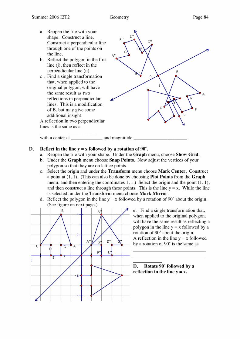
a. Reopen the file with your shape. Construct a line. Construct a perpendicular line through one of the points on the line.
b. Reflect the polygon in the first line (j), then reflect in the perpendicular line (n).
c . Find a single transformation that, when applied to the original polygon, will have the same result as two reflections in perpendicular lines. This is a modification of B, but may give some additional insight.
A reflection in two perpendicular lines is the same as a _______________________
with a center at _____________ and magnitude ______________________. D. Reflect in the line y = x followed by a rotation of 90˚. a. Reopen the file with your shape. Under the Graph menu, choose Show Grid. b. Under the Graph menu choose Snap Points. Now adjust the vertices of your
polygon so that they are on lattice points. c. Select the origin and under the Transform menu choose Mark Center. Construct
a point at (1, 1). (This can also be done by choosing Plot Points from the Graph menu, and then entering the coordinates 1, 1.) Select the origin and the point (1, 1), and then construct a line through these points. This is the line y = x. While the line is selected, under the Transform menu choose Mark Mirror.
d. Reflect the polygon in the line y = x followed by a rotation of 90˚ about the origin. (See figure on next page.)
e. Find a single transformation that, when applied to the original polygon, will have the same result as reflecting a polygon in the line y = x followed by a rotation of 90˚ about the origin. A reflection in the line y = x followed by a rotation of 90˚ is the same as D. Rotate 90˚ followed by a reflection in the line y = x.
n
j
C''
A''
B''
D''
E''F''
G''
A
B
C
D
E
F
G
4
2
-2
- 4
- 5 5
G''
F'' E''
D'' C''
B''
A''
A
B
CD
E F
G

Summer 2006 I2T2 Geometry Page 85
a. Undo the previous reflection and rotation until you are back at the polygon and line y = x.
b. Select the origin and mark it as the center of rotation. Select the line y = x and mark it as a mirror.
c. Rotate the polygon 90˚ about the origin followed by a reflection in the line y = x.
You might have to change your polygon somewhat to determine the final result. (See example at right.)
d. Is this the same transformation as the previous?
e. Find a single transformation that, when applied to the original polygon, will have the same result.
F. Reflection in x-axis followed by a 90˚ rotation about the origin. a. Undo the previous reflections and rotations until you are back to your shape and the grid. b. Select the origin and mark it as the center of rotation. Select the x-axis and mark it as a mirror. c. Reflect the polygon in x-axis followed by a rotation of 90˚ about the origin. (See left sketch at left.) d. Find a single transformation that, when applied to the original polygon, will have the same result.
6
4
2
-2
- 4
- 5 5
C'' G''
F''E''
D''
B''
A''
A
B
CD
E F
G
4
2
-2
- 4
- 5 5
G''F''
E'' D''
C''
B''
A''
A
B
CD
E F
G

Summer 2006 I2T2 Geometry Page 86
G. Rotation of 90˚ about the origin followed by a reflection in the x-axis. a. Undo the previous reflections and rotations until you are back to your shape and the
grid. b. Select the origin and mark it as the center of rotation. Select the x-axis and mark it
as a mirror. c. Rotate the polygon 90˚ about the origin followed by a reflection in the x-axis. (See
sketch at right.) d. Is this the same as the previous transformation? e. What single transformation, when applied to the original polygon, will have the
same result?
6
4
2
-2
- 4
- 5
G'' F''
E''D''
C''
B''
A''
A
B
CD
E F
G
Summer 2006 I2T2 Geometry Page 87
Exploration #3
Glide Reflections A glide reflection is a combination of a translation and a reflection in parallel lines. a. Reload your polygon from Exploration #1 or undo all previous rotations and
reflections. b. Draw a horizontal line on the screen. (Hold down shift key to make sure it is
horizontal.) While the line is selected, under the Transform menu choose Mark Mirror.
c. In one corner, out of the way, draw a horizontal segment. (This is the vector, or delta-x and delta-y for our translation.) Click on the left vertex of the segment, then the right vertex. Under Transform choose Mark Vector.
Now you have a figure, a line for reflection, and a translation defined by a vector. Remember for a glide reflection, the glide should be parallel to the line of reflection, which is why we made them both horizontals.
Reflection: d. Select the polygon. If you have selected anything extra, click to deselect. e. Under Transform choose Reflect. Translation f. The reflected polygon should now be selected. Under Transform choose Translate. g. You will get a dialog box. Marked Vector should be selected. h. Select the middle polygon. (If the polygons overlap, drag the segment to make the
vector longer. Remember to hold down the shift key to keep it horizontal.) Under the Display menu choose Hide.
You now have done one glide reflection. It does not matter whether you do the reflection followed by the translation, or the translation followed by the reflection. The end result is the same. Iterate i. Select the vertices of the initial image. Under the Transform menu, choose
Iterate. j. A dialog box will appear with the vertices of the initial image. Click the
corresponding vertex in the final image. You should see the resulting transformation appear as you step through the matchings.
Summer 2006 I2T2 Geometry Page 88
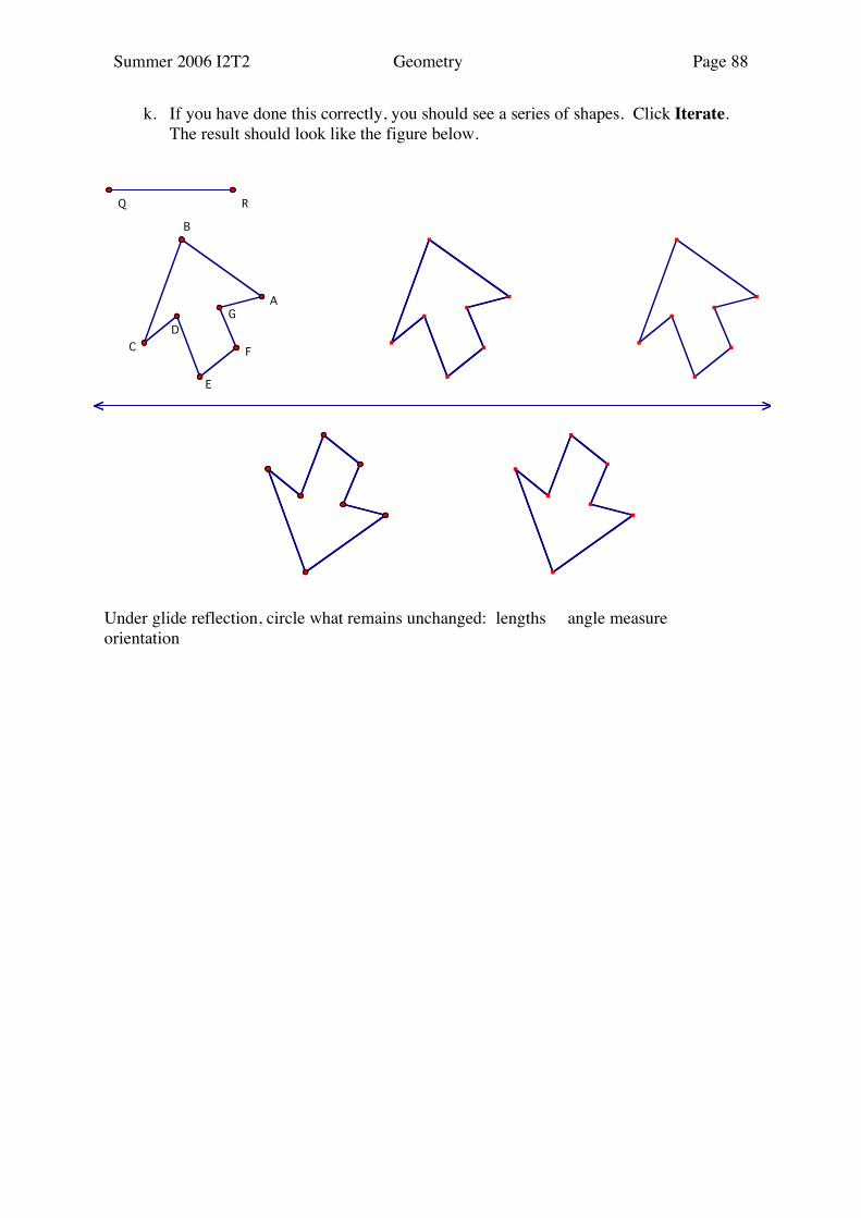
k. If you have done this correctly, you should see a series of shapes. Click Iterate. The result should look like the figure below.
Under glide reflection, circle what remains unchanged: lengths angle measure orientation
A
B
C
D
E
F
G
Q R

Summer 2006 I2T2 Geometry Page 89
Problem Solving with Reflections [Key Idea 1, 3, 4, 5, 7] Exploration #1
Reflected Quadrilaterals Objective: To investigate the relationships between quadrilateral ABCD and a second quadrilateral formed by reflecting the intersection of the diagonals in each of the four sides. (This is based on an investigation that first appeared in the manual accompanying the Geometric Supposer–Quadrilaterals software) I. Parallelogram a. Construct a generic
parallelogram ABCD as follows: 1) Construct AB and BC . 2) Through C construct a line
parallel to AB . 3) Through A construct a line
parallel to BC . 4) Construct a point D where
these two lines intersect. Double-click on the label and choose "Use Label in Custom Tools."
5) Hide the lines and construct segments AD and CD .
b. Construct diagonals AC and BD . c. Label their intersection point E. Double-click on the label and choose "Use Label in
Custom Tools." d. Reflect E in AB , BC , CD , and AD as follows: Select AB , under the Transform
menu choose Mark Mirror. Select E and under Transform choose Reflect. Relabel this point F using the Text tool, click in the box where it says "Use Label in Custom Tools."
Now repeat these steps to reflect E in BC , CD , and AD , relabeling the points G, H, and I respectively. Make sure that in each case you check the box to use the new label in custom tools. You should have four points F, G, H, I as in the picture above.
e. Connect points F, G, H, and I by selecting them in order using the arrow tool, then under Construct choose Segments.
f. What kind of figure is FGHI? Measure the sides and angles of FGHI in order to categorize the shape. Record these measurements on the DATA sheet (p. 60). To determine if two sides are parallel, you can measure the slope of the line segments.
g. State your conclusions after the data. Drag points B and C to verify the shape of FGHI.
We want to repeat this experiment with other parallelograms, such as rhombus, rectangle, and square. To make this easier, we want to create a custom tool. Select everything. While all of these are selected, click on the custom tool button in the toolbox. (Looks like a triangle with three dots. Choose Create New Tool. Then give your tool a name, such as
IH
G
F
E
D
A B
C

Summer 2006 I2T2 Geometry Page 90
refl.parallelograms. You can save this tool by going to file, Save As, locating the Tool Folder in the Sketchpad folder, and naming the sketch (refl-para.gsp). This tool will be available as long as the sketch is open. If you close the sketch without saving, the tool disappears. II. Rhombus: Get a new sketch. Construct segment AB. Now select point B and segment AB. Under the Construct menu choose Circle by Center+Radius. While the circle is selected, under Construct choose Point on Circle. Now hide the circle and label the point C. Click on the toolbox, scroll down to "Other Documents" where you should see the document where you created the tool. (May be called "Untitled 4" or something like that.) You should see your tool listed to the right. Select that tool, then go to your rhombus, point at A and click, then point at B and click, then point at C and click. Parallelogram ABCD will be a rhombus. At this point you should have quadrilateral FGHI constructed. What is FGHI? Is it also a special parallelogram? Identify what kind of parallelogram it is. Record your measurements and conjectures on the DATA sheet (p. 60). III. Rectangle: Get a new sketch. Construct segment AB. Through point B construct a perpendicular to AB . Construct a point C on this line. Hide the perpendicular and construct segment BC. Click on the toolbox, and select the tool for reflected parallelograms, then go to your three points and click on A, B, and C in that order. Parallelogram ABCD will be a rectangle. At this point you should have quadrilateral FGHI constructed. Drag C so you don't have a square. What is FGHI? Is it also a special parallelogram? Identify what kind of parallelogram it is. Record your measurements and conjectures on the DATA sheet (p. 60). IV. Square: Get a new sketch. Construct segment AB. Now select point B and under the Transform menu Mark Center. Select point A and under the Transform menu choose Rotate. Type in –90˚. Label the point C. Click on the toolbox, and select the tool for reflected parallelograms, then go to your three points and click on A, B, and C in that order. Parallelogram ABCD will be a square. At this point you should have quadrilateral FGHI constructed. What is FGHI? Is it also a special parallelogram? Identify what kind of parallelogram it is. Record your measurements and conjectures on the DATA sheet (p. 60).
Summer 2006 I2T2 Geometry Page 91
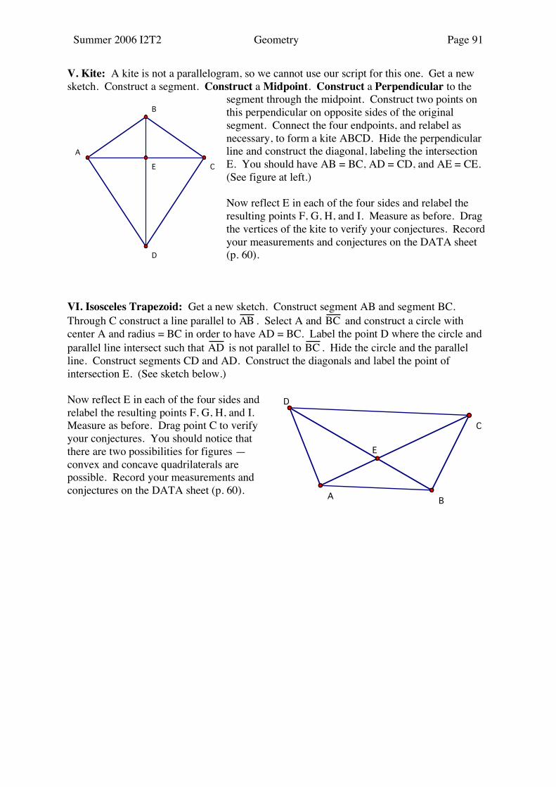
V. Kite: A kite is not a parallelogram, so we cannot use our script for this one. Get a new sketch. Construct a segment. Construct a Midpoint. Construct a Perpendicular to the
segment through the midpoint. Construct two points on this perpendicular on opposite sides of the original segment. Connect the four endpoints, and relabel as necessary, to form a kite ABCD. Hide the perpendicular line and construct the diagonal, labeling the intersection E. You should have AB = BC, AD = CD, and AE = CE. (See figure at left.) Now reflect E in each of the four sides and relabel the resulting points F, G, H, and I. Measure as before. Drag the vertices of the kite to verify your conjectures. Record your measurements and conjectures on the DATA sheet (p. 60).
VI. Isosceles Trapezoid: Get a new sketch. Construct segment AB and segment BC. Through C construct a line parallel to AB . Select A and BC and construct a circle with center A and radius = BC in order to have AD = BC. Label the point D where the circle and parallel line intersect such that AD is not parallel to BC . Hide the circle and the parallel line. Construct segments CD and AD. Construct the diagonals and label the point of intersection E. (See sketch below.)
Now reflect E in each of the four sides and relabel the resulting points F, G, H, and I. Measure as before. Drag point C to verify your conjectures. You should notice that there are two possibilities for figures — convex and concave quadrilaterals are possible. Record your measurements and conjectures on the DATA sheet (p. 60).
E
A
C
B
D
E
D
AB
C

Summer 2006 I2T2 Geometry Page 92
DATA SHEET Shape of ABCD
FG
GH
HI
IF
∠FGH
∠GHI
∠HIF
∠IFG
Shape of FGHI
Parallelogram
Rhombus
Rectangle
Square
Kite
Isosceles trapezoid
Isosceles trapezoid
Conclusions a. If ABCD is a parallelogram, then FGHI is a .
b. If ABCD is a rhombus, then FGHI is a
c. If ABCD is a rectangle, then FGHI is a
d. If ABCD is a square, then FGHI is a
e. If ABCD is a kite, then FGHI is a
f. If ABCD is an isosceles trapezoid, then FGHI is a or
Summer 2006 I2T2 Geometry Page 93
Exploration #2
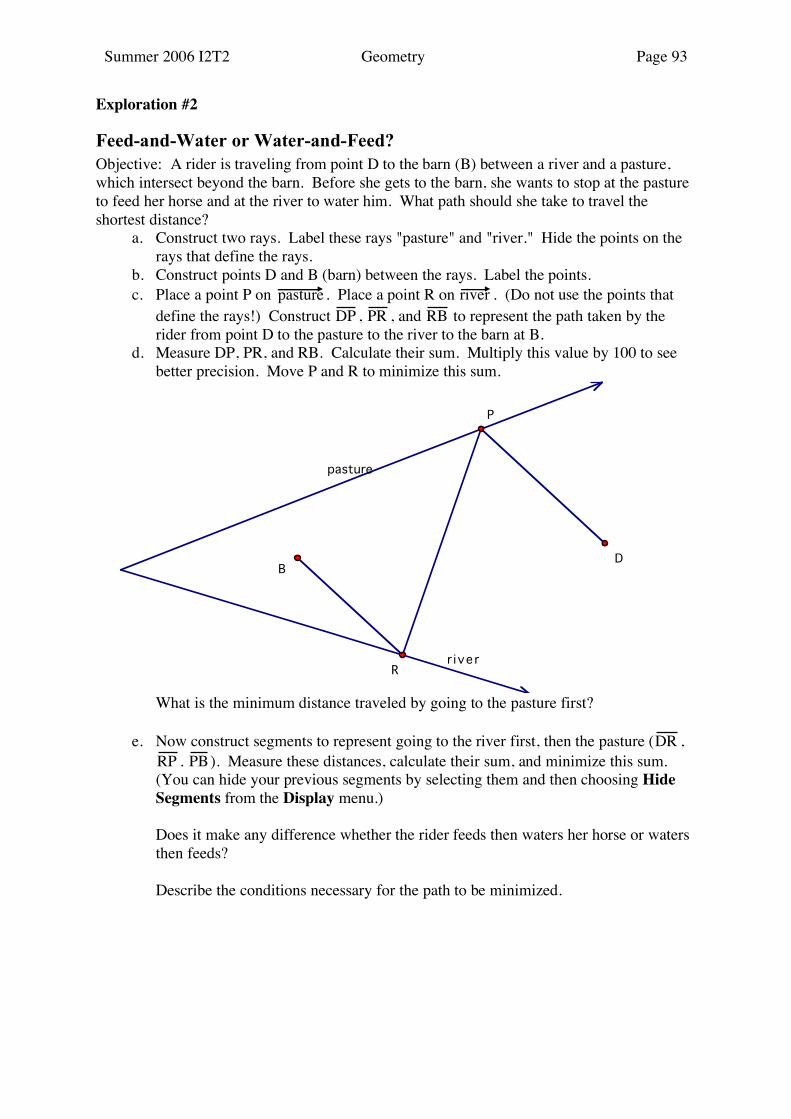
Feed-and-Water or Water-and-Feed? Objective: A rider is traveling from point D to the barn (B) between a river and a pasture, which intersect beyond the barn. Before she gets to the barn, she wants to stop at the pasture to feed her horse and at the river to water him. What path should she take to travel the shortest distance? a. Construct two rays. Label these rays "pasture" and "river." Hide the points on the
rays that define the rays. b. Construct points D and B (barn) between the rays. Label the points. c. Place a point P on pasture . Place a point R on river . (Do not use the points that
define the rays!) Construct DP , PR , and RB to represent the path taken by the rider from point D to the pasture to the river to the barn at B.
d. Measure DP, PR, and RB. Calculate their sum. Multiply this value by 100 to see better precision. Move P and R to minimize this sum.
What is the minimum distance traveled by going to the pasture first? e. Now construct segments to represent going to the river first, then the pasture (DR ,
RP . PB ). Measure these distances, calculate their sum, and minimize this sum. (You can hide your previous segments by selecting them and then choosing Hide
Segments from the Display menu.) Does it make any difference whether the rider feeds then waters her horse or waters
then feeds? Describe the conditions necessary for the path to be minimized.
pasture
r iver
BD
P
R
Summer 2006 I2T2 Geometry Page 94
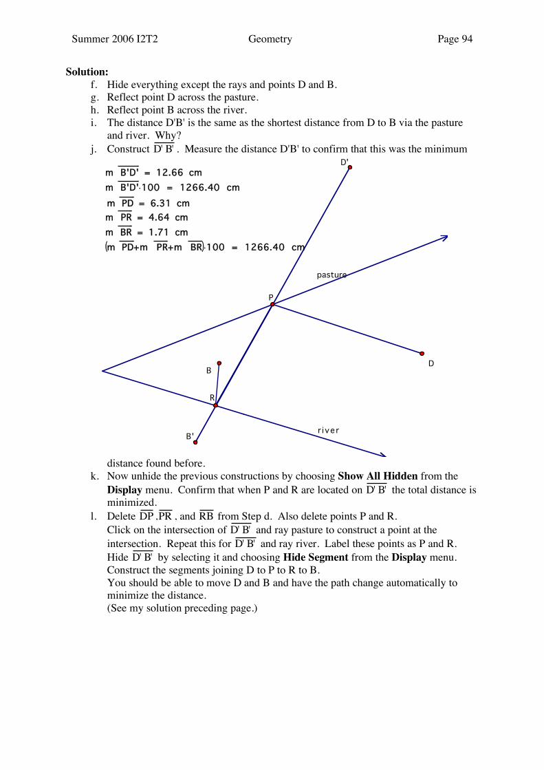
Solution: f. Hide everything except the rays and points D and B. g. Reflect point D across the pasture. h. Reflect point B across the river. i. The distance D'B' is the same as the shortest distance from D to B via the pasture
and river. Why? j. Construct D' B' . Measure the distance D'B' to confirm that this was the minimum
distance found before. k. Now unhide the previous constructions by choosing Show All Hidden from the
Display menu. Confirm that when P and R are located on D' B' the total distance is minimized.
l. Delete DP ,PR , and RB from Step d. Also delete points P and R. Click on the intersection of D' B' and ray pasture to construct a point at the
intersection. Repeat this for D' B' and ray river. Label these points as P and R. Hide D' B' by selecting it and choosing Hide Segment from the Display menu. Construct the segments joining D to P to R to B. You should be able to move D and B and have the path change automatically to
minimize the distance. (See my solution preceding page.)
pasture
r iver
m PD+m PR+m BR( )!100 = 1266.40 cm
m BR = 1.71 cm
m PR = 4.64 cm
m PD = 6.31 cm
m B'D'!100 = 1266.40 cm
m B'D' = 12.66 cm
P
R
B'
D'
BD
Summer 2006 I2T2 Geometry Page 95
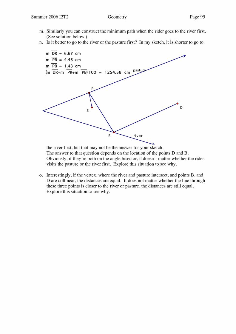
m. Similarly you can construct the minimum path when the rider goes to the river first. (See solution below.)
n. Is it better to go to the river or the pasture first? In my sketch, it is shorter to go to
the river first, but that may not be the answer for your sketch. The answer to that question depends on the location of the points D and B.
Obviously, if they’re both on the angle bisector, it doesn’t matter whether the rider visits the pasture or the river first. Explore this situation to see why.
o. Interestingly, if the vertex, where the river and pasture intersect, and points B, and
D are collinear, the distances are equal. It does not matter whether the line through these three points is closer to the river or pasture, the distances are still equal. Explore this situation to see why.
pasture
r iver
m DR+m PR+m PB( )!100 = 1254.58 cm
m PB = 1.43 cm
m PR = 4.45 cm
m DR = 6.67 cm
R
P
BD
Summer 2006 I2T2 Geometry Page 96
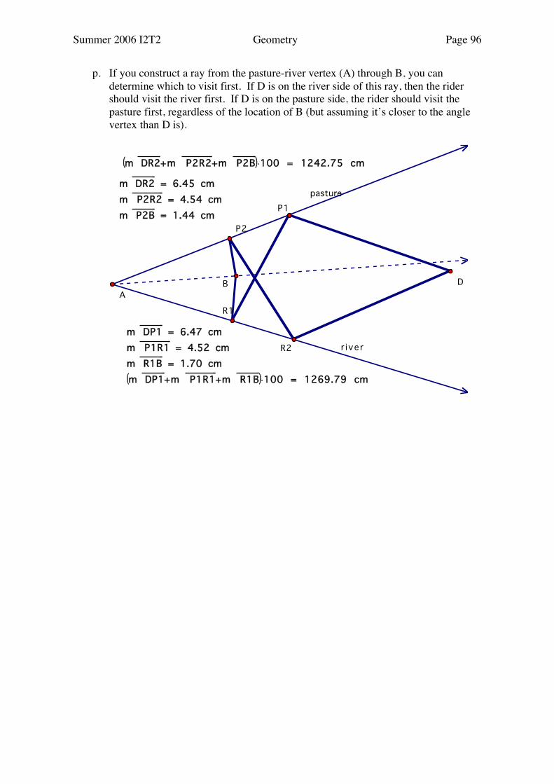
p. If you construct a ray from the pasture-river vertex (A) through B, you can determine which to visit first. If D is on the river side of this ray, then the rider should visit the river first. If D is on the pasture side, the rider should visit the pasture first, regardless of the location of B (but assuming it’s closer to the angle vertex than D is).
pasture
r iver
m DP1+m P1R1+m R1B( )!100 = 1269.79 cm
m R1B = 1.70 cm
m P1R1 = 4.52 cm
m DP1 = 6.47 cm
m DR2+m P2R2+m P2B( )!100 = 1242.75 cm
m P2B = 1.44 cm
m P2R2 = 4.54 cm
m DR2 = 6.45 cm
R1
P1
R2
P2
A
B D
Summer 2006 I2T2 Geometry Page 97
Symmetries
[Key Idea 1, 3, 4]
Exploration #1
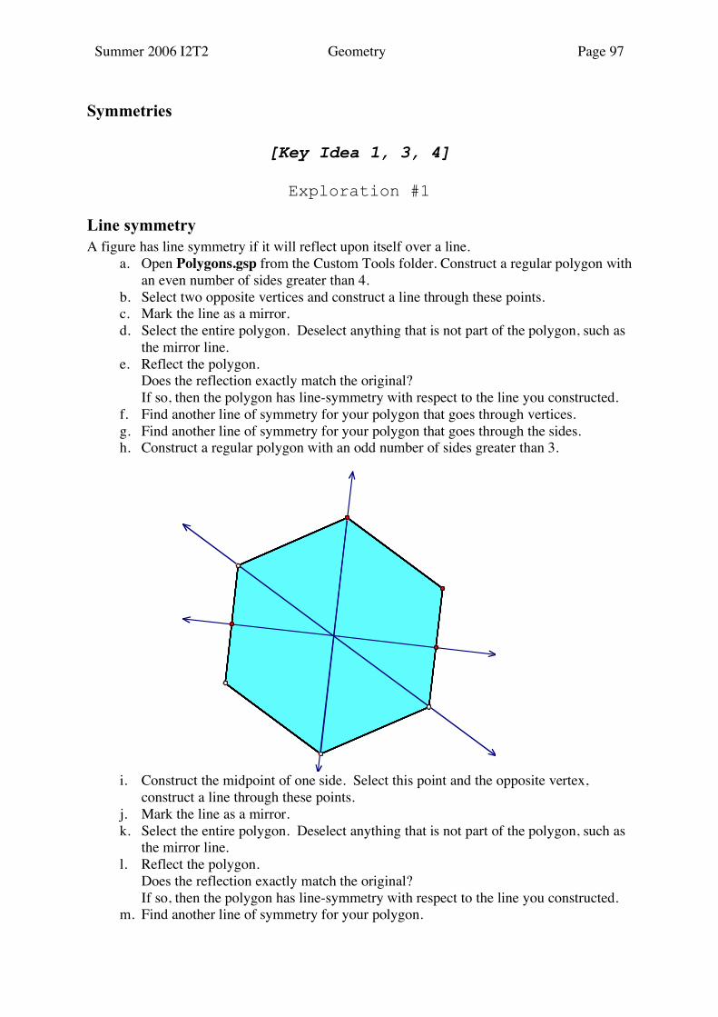
Line symmetry A figure has line symmetry if it will reflect upon itself over a line. a. Open Polygons.gsp from the Custom Tools folder. Construct a regular polygon with
an even number of sides greater than 4. b. Select two opposite vertices and construct a line through these points. c. Mark the line as a mirror. d. Select the entire polygon. Deselect anything that is not part of the polygon, such as
the mirror line. e. Reflect the polygon. Does the reflection exactly match the original? If so, then the polygon has line-symmetry with respect to the line you constructed. f. Find another line of symmetry for your polygon that goes through vertices. g. Find another line of symmetry for your polygon that goes through the sides. h. Construct a regular polygon with an odd number of sides greater than 3.
i. Construct the midpoint of one side. Select this point and the opposite vertex, construct a line through these points.
j. Mark the line as a mirror. k. Select the entire polygon. Deselect anything that is not part of the polygon, such as
the mirror line. l. Reflect the polygon. Does the reflection exactly match the original? If so, then the polygon has line-symmetry with respect to the line you constructed. m. Find another line of symmetry for your polygon.
Summer 2006 I2T2 Geometry Page 98
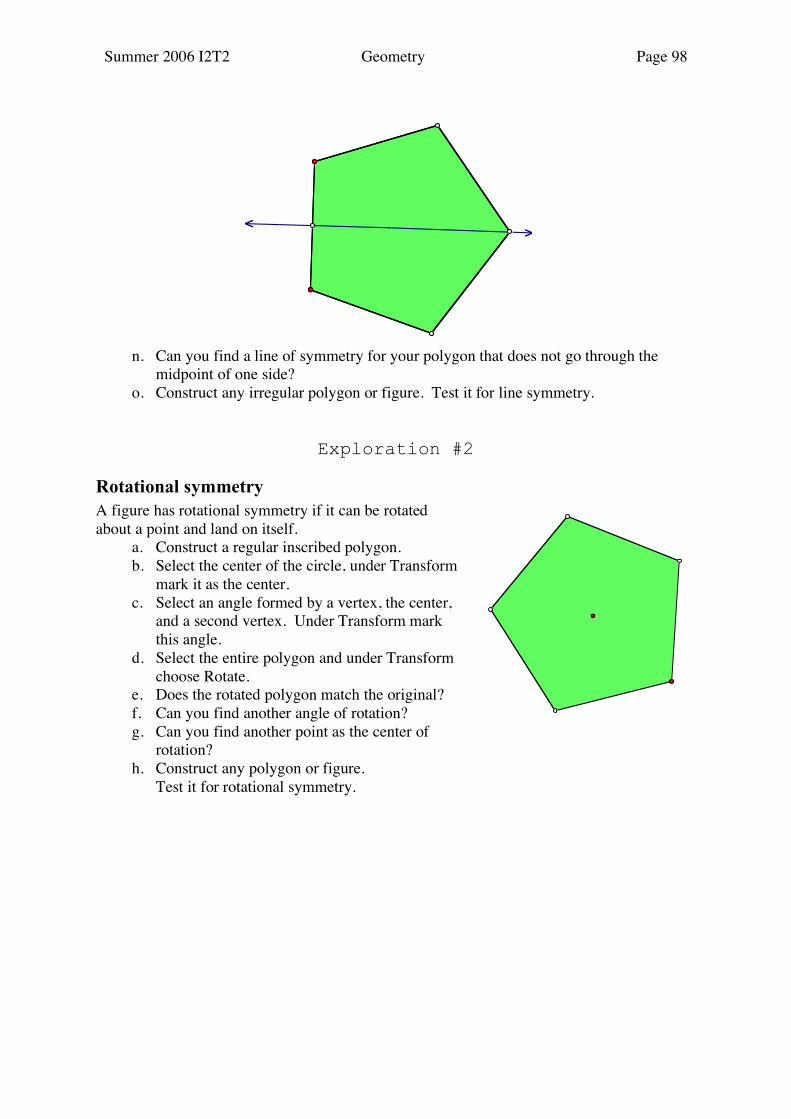
n. Can you find a line of symmetry for your polygon that does not go through the midpoint of one side?
o. Construct any irregular polygon or figure. Test it for line symmetry.
Exploration #2
Rotational symmetry A figure has rotational symmetry if it can be rotated about a point and land on itself. a. Construct a regular inscribed polygon. b. Select the center of the circle, under Transform
mark it as the center. c. Select an angle formed by a vertex, the center,
and a second vertex. Under Transform mark this angle.
d. Select the entire polygon and under Transform choose Rotate.
e. Does the rotated polygon match the original? f. Can you find another angle of rotation? g. Can you find another point as the center of
rotation? h. Construct any polygon or figure. Test it for rotational symmetry.
Summer 2006 I2T2 Geometry Page 99
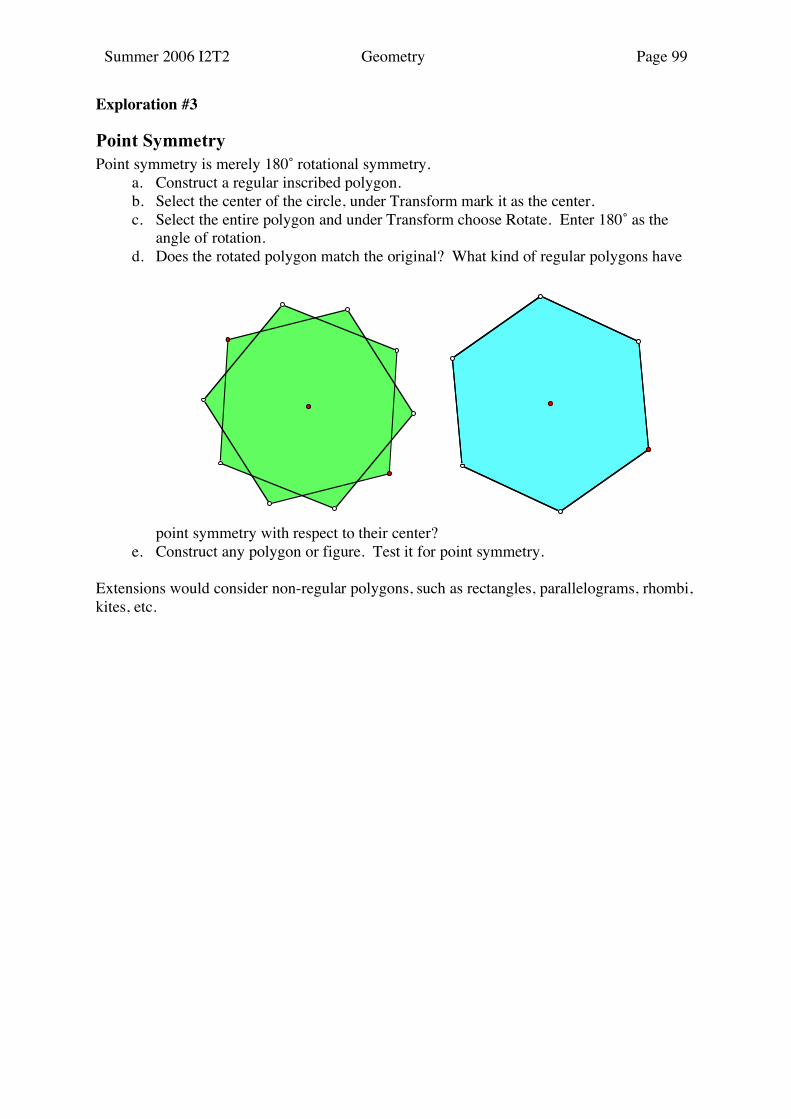
Exploration #3
Point Symmetry Point symmetry is merely 180˚ rotational symmetry. a. Construct a regular inscribed polygon. b. Select the center of the circle, under Transform mark it as the center. c. Select the entire polygon and under Transform choose Rotate. Enter 180˚ as the
angle of rotation. d. Does the rotated polygon match the original? What kind of regular polygons have
point symmetry with respect to their center? e. Construct any polygon or figure. Test it for point symmetry. Extensions would consider non-regular polygons, such as rectangles, parallelograms, rhombi, kites, etc.

Summer 2006 I2T2 Geometry Page 100
Coordinate Geometry
[Key Idea 1, 3, 4, 5, 7]
Exploration #1
Reflections using Coordinates
Under Edit Preferences, set the unit distance to cm. and units, set the angle to degree and tenths, and set the computations to tenths. Open a new sketch, from the Graph menu choose Show Grid and Snap Points. Select the two points at the origin and at (1,0) and under Display choose Hide Points. a. Place points on the grid to create an irregular polygon. Select the points in order
and Construct Segments. Select the points and under Measure choose Coordinates. b. Select the y-axis and under Transform mark as Mirror. c. Select the entire polygon. Reflect. Measure the new coordinates. d. Compare the coordinates of the original points and the reflected points. Write a rule
for reflecting in the y-axis. e. Undo the reflection and its coordinates. Select the x-axis and under Transform
mark as Mirror.
f. Select the original polygon. Reflect. Measure the new coordinates. g. Compare the coordinates of the original points and the reflected points. Write a rule
for reflecting in the x-axis. h. Undo the reflection and its coordinates. Plot a point at (0,0) and (1,1). Construct
the line through these points, which is the line y = x. Select this line and under the Transform menu mark it as a Mirror.
i. Select the original polygon. Reflect. Measure the new coordinates. j. Compare the coordinates of the original points and the reflected points. Write a rule
for reflecting in the line y = x. k. Undo the reflection and its coordinates. Select the origin and the line y = x.
Construct a perpendicular. This is the line y = –x. Select this line and under the Transform menu mark it as a Mirror.
6
4
2
-10 - 5 5 10
H': (-7.0, 6.0)
G': (-5.0, 4.0)
F': (-7.0, 4.0)
E': (-7.0, 3.0)
D': (-4.0, 3.0)
C': (-4.0, 2.0)
B': (-3.0, 2.0)
A': (-3.0, 6.0)
H: (7.0, 6.0)
G: (5.0, 4.0)
F: (7.0, 4.0)
E: (7.0, 3.0)
D: (4.0, 3.0)
C: (4.0, 2.0)
B: (3.0, 2.0)
A: (3.0, 6.0)H'
G'F'
E' D'
C' B'
A' A
B C
D E
FG
H

Summer 2006 I2T2 Geometry Page 101
l. Select the original polygon. Reflect. Measure the new coordinates. m. Compare the coordinates of the original points and the reflected points. Write a rule
for reflecting in the line y = –x.
6
4
2
- 2
- 4
- 6
- 8
-10 - 5 5 10
H': (-6.0, -7.0)
G': (-4.0, -5.0)
F': (-4.0, -7.0)
E': (-3.0, -7.0)
D': (-3.0, -4.0)
C': (-2.0, -4.0)
B': (-2.0, -3.0)
A': (-6.0, -3.0)
H: (7.0, 6.0)
G: (5.0, 4.0)
F: (7.0, 4.0)
E: (7.0, 3.0)
D: (4.0, 3.0)
C: (4.0, 2.0)
B: (3.0, 2.0)
A: (3.0, 6.0)
H'
G'
F' E'
D' C'
B'A'
A
B C
D E
FG
H
Summer 2006 I2T2 Geometry Page 102
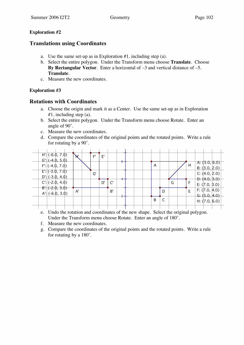
Exploration #2
Translations using Coordinates a. Use the same set-up as in Exploration #1, including step (a). b. Select the entire polygon. Under the Transform menu choose Translate. Choose
By Rectangular Vector. Enter a horizontal of –3 and vertical distance of –5. Translate.
c. Measure the new coordinates. Exploration #3
Rotations with Coordinates a. Choose the origin and mark it as a Center. Use the same set-up as in Exploration
#1, including step (a). b. Select the entire polygon. Under the Transform menu choose Rotate. Enter an
angle of 90˚. c. Measure the new coordinates. d. Compare the coordinates of the original points and the rotated points. Write a rule
for rotating by a 90˚.
e. Undo the rotation and coordinates of the new shape. Select the original polygon. Under the Transform menu choose Rotate. Enter an angle of 180˚.
f. Measure the new coordinates. g. Compare the coordinates of the original points and the rotated points. Write a rule
for rotating by a 180˚.
6
4
2A': (-6.0, 3.0)
B': (-2.0, 3.0)
C': (-2.0, 4.0)
D': (-3.0, 4.0)
E': (-3.0, 7.0)
F': (-4.0, 7.0)
G': (-4.0, 5.0)
H': (-6.0, 7.0)
H: (7.0, 6.0)
G: (5.0, 4.0)
F: (7.0, 4.0)
E: (7.0, 3.0)
D: (4.0, 3.0)
C: (4.0, 2.0)
B: (3.0, 2.0)
A: (3.0, 6.0)
A' B'
C'D'
E'F'
G'
H'
A
B C
D E
FG
H

Summer 2006 I2T2 Geometry Page 103
h. Again undo the rotated polygon and its coordinates. Select the original polygon and
under the Transform menu choose Rotate. Enter an angle of 270˚. i. Measure the new coordinates. j. Compare the coordinates of the original points and the rotated points. Write a rule
for rotating by a 270˚.
6
4
2
- 2
- 4
- 6
- 5 5 10
H': (-7.0, -6.0)
G': (-5.0, -4.0)
F': (-7.0, -4.0)
E': (-7.0, -3.0)
D': (-4.0, -3.0)
C': (-4.0, -2.0)
B': (-3.0, -2.0)
A': (-3.0, -6.0)
H: (7.0, 6.0)
G: (5.0, 4.0)
F: (7.0, 4.0)
E: (7.0, 3.0)
D: (4.0, 3.0)
C: (4.0, 2.0)
B: (3.0, 2.0)
A: (3.0, 6.0)
H'
G'F'
E' D'
C' B'
A'
A
B C
D E
FG
H
6
4
2
- 2
- 4
- 6
- 8
5 10
H': (6.0, -7.0)
G': (4.0, -5.0)
F': (4.0, -7.0)
E': (3.0, -7.0)
D': (3.0, -4.0)
C': (2.0, -4.0)
B': (2.0, -3.0)
A': (6.0, -3.0)
H: (7.0, 6.0)
G: (5.0, 4.0)
F: (7.0, 4.0)
E: (7.0, 3.0)
D: (4.0, 3.0)
C: (4.0, 2.0)
B: (3.0, 2.0)
A: (3.0, 6.0)
H'
G'
F'E'
D'C'
B' A'
A
B C
D E
FG
H