transferjet consortium · transferjet™ technology overview ... (near field communications). by...
TRANSCRIPT

TransferJetTM Overview TJC_025_TransferJet_Overview-rev.1.5
© 2010TransferJet Consortium
TTrraannssffeerrJJeett™™ OOvveerrvviieeww CCoonncceepptt aanndd TTeecchhnnoollooggyy
RReevv.. 11..55
August 2015
TransferJet Consortium

TransferJetTM Overview TJC_025_TransferJet_Overview-rev.1.5
© 2010TransferJet Consortium Page 2 / 45
Notice
The information contained herein is provided on an “as is” basis, and the authors of this document hereby disclaim all other warranties and conditions, either express, implied or statutory, including but not limited to, any implied warranties, duties or conditions of merchantability, or fitness for a particular purpose. TransferJet Consortium disclaims all liability, including liability for infringement of any proprietary rights, relating to use of information in this document. No license, express or implied, by estoppels or otherwise, to any intellectual property rights is granted herein. TransferJet and TransferJet logos are licensed by the TransferJet Consortium. The OBEX word mark and logo are trademarks owned by Infrared Data Association (IrDA®). Other names and brands may be claimed as the property of others. © 2010 TransferJet Consortium Copying or other form of reproduction and/or distribution of these works are strictly prohibited.
TransferJetTM Overview TJC_025_TransferJet_Overview-rev.1.5
© 2010TransferJet Consortium Page 3 / 45
INTRODUCTION Two worlds exist for today’s consumer: content creation and content playback. The traditional end user still consumes multimedia content by watching TV, listening to music, and viewing family photos. But many end users spend almost as much time producing content. They produce video, music, and photos using cameras, camcorders, cell phones, and digital video recorders (DVRs) to shoot, snap, and record events whenever and wherever they happen. The reason this has become so popular is simple: it is very easy to create content with modern equipment. But there is a problem. Content is easier to create than to transfer. This limits the potential for playback and sharing and creates a kind of bottleneck between content production and content consumption. For example, end users want to view digital family photos on their big screen TV. It is possible today using cables and menus. But is that the best way? Does the complexity allow people to fully enjoy photos at their convenience? Is every member of the family able to view photos in this way? What about the end user that wants to transfer digital photos to their PC? That is also possible using a memory card or a USB cable. And many people successfully navigate that existing procedure. But is there a better way? Or does this procedure also limit the enjoyment factor? Many other opportunities exist for sharing content between devices. Every device has some advantage. Some, like camcorders and digital cameras, are better at creating content. Others, like TVs and notebook computers, are better at playing back content. Still others, like cell phones, fulfill both roles in a portable platform. Clearly, the ability to share content between devices is necessary to bridge the two worlds thus enhancing the enjoyment and value of individual devices. This technical overview presents a solution – TransferJet™ – which solves the content sharing problem in a way that also achieves high performance, low cost, high security, and most importantly, extreme ease of use.

TransferJetTM Overview TJC_025_TransferJet_Overview-rev.1.5
© 2010TransferJet Consortium Page 4 / 45
Table of Contents
1. Technology Development ................................................................................................ 6 1.1. Initial Reference Use Case..................................................................................... 6
1.1.1. File Exchange .................................................................................................. 6 1.1.2. File access and real time content consumption ............................................ 8 1.1.3. Print Services .................................................................................................. 8
1.2. Technical Implementation ..................................................................................... 9 2. TransferJet™ Technology Overview ............................................................................ 10 2.1. TransferJet™ Basics ............................................................................................ 10 2.2. TransferJet™ Security .......................................................................................... 11 2.3. TransferJet™ Connection .................................................................................... 12 2.4. Unique Coupler Element ..................................................................................... 12 2.5. Connection and Sequence .................................................................................... 14 2.6. Specification Details ............................................................................................. 15
3. Architecture and Hierarchy ......................................................................................... 16 3.1. Physical Layer Overview ..................................................................................... 16 3.2. Modulation Scheme .............................................................................................. 17 3.3. Frame Format ....................................................................................................... 17 3.4. Connection Layer Overview................................................................................. 18
3.4.1. CNL state ....................................................................................................... 19 4. Protocol Conversion Layer Overview .......................................................................... 21 4.1. Protocol Conversion Layer Controller................................................................. 21
4.1.1. Services .......................................................................................................... 21 4.1.2. Device Model and Device Modes .................................................................. 21 4.1.3. Application-Service Parameter .................................................................... 22 4.1.4. PCL Controller Message ............................................................................... 24 4.1.5. Overview Flow of PCL Controller ................................................................ 26 4.1.6. PCL Controller state ..................................................................................... 27
4.2. Overview of OBEX Application and Adapter ...................................................... 28 4.2.1. Format of Protocol Data Unit ....................................................................... 29 4.2.2. Sequence ........................................................................................................ 30
4.3. Overview of SCSI Application and Adapter........................................................ 31 4.3.1. SCSI Implementations over TransferJet™ ................................................. 32 4.3.2. SCSI Command execution sequence ............................................................ 33 4.3.3. Requirements for logical unit ....................................................................... 36

TransferJetTM Overview TJC_025_TransferJet_Overview-rev.1.5
© 2010TransferJet Consortium Page 5 / 45
5. Certification Program ................................................................................................... 37 6. Trademark and Logo .................................................................................................... 39 7. What is the TransferJet Consortium? ......................................................................... 41 8. TransferJet Consortium Goals..................................................................................... 41 9. TransferJet Consortium Organizational Structure and Working Groups ............... 41 10. Membership................................................................................................................... 43 11. Abbreviations and Acronyms ....................................................................................... 44 12. References ..................................................................................................................... 45 13. Qualified Test Laboratory (as of August 2015) ........................................................... 45

TransferJetTM Overview TJC_025_TransferJet_Overview-rev.1.5
© 2010TransferJet Consortium Page 6 / 45
1. Technology Development
TransferJet™ is a new wireless technology that combines the speed of UWB (Ultra-Wide Band) with the ease of NFC (Near Field Communications). By doing so, TransferJet™ delivers a transfer speed of 560 Mbps available. The key concept of TransferJet™ is this “touch” model of user operation. This model requires only a simple touch motion from the user to make things happen. Touch is such a natural motion that people tend to “get it” very quickly. Clearly, touch is a very natural and intuitive motion. From a user standpoint, TransferJet™ can be thought of as a universal touch-activated interface which instantly connects a wide variety of consumer (and non-consumer) electronic products. The TransferJet™ technical specifications have been developed in order to realize simplicity of use based on the “touch” model. 1.1. Initial Reference Use Case
The TransferJet Consortium has studied various usage scenarios that are suitable for this “touch” model and prioritized them according to consumer/commercial needs. The TransferJet Consortium ultimately selected the following three use cases as the initial reference use cases. The TransferJet™ 1.0 technical specifications were developed to implement these initial reference use cases. 1.1.1. File Exchange
TransferJet™ enables high speed transfer of large data files (photos, video, images, etc) between two electronic products such as mobile phones, digital cameras, camcorders, computers, TVs, game products, and printers. Using this technology in its simplest form, data can be sent at high speed with just a single touch.
PUSHMobile terminal
User OperationFile Select
Fig. 1-1 File Exchange (Push)

TransferJetTM Overview TJC_025_TransferJet_Overview-rev.1.5
© 2010TransferJet Consortium Page 7 / 45
In this use case, a user can push any data file from her/his mobile terminal to another mobile/stationary terminal just by touching. In certain cases, the user may select the specific data to send as well as the location to store (or method to process) the received data before the actual touch operation. For example, students can share music with friends merely by touching the cell phone to the music player. A tourist can store and archive digital video simply by placing the camcorder close to the PC. Alternatively, the user can get any data file from another mobile/stationary terminal with a similar touch operation. In most cases, the data to transfer has been selected by the sender and, therefore, the receiver does not have to select the file but just touch and receive it.
PULL Mobile terminal
User OperationFile Select
User OperationFile Select
Stationary Fig. 1-2 File Exchange (Pull)
As examples of location-based public applications, it is possible to create digital signage and digital kiosks. A person might get files such as coupons, movie trailers, event info or sound clips by touching TransferJet™ pads (target points) placed in public locations. A theme park visitor could download electronic maps and event schedules by touching TransferJet™ pads at the park entrance or other locations.

TransferJetTM Overview TJC_025_TransferJet_Overview-rev.1.5
© 2010TransferJet Consortium Page 8 / 45
1.1.2. File access and real time content consumption
A user might access a file system on her/his mobile terminal (such as cell phone, digital camera, or camcorder) by placing it on a TransferJet™ target point connected to a host terminal such as a computer, digital TV, projector or other device. Once connected, one can access, retrieve, manage, and execute any files on the mobile terminal in the same way as local files. The user can play back and enjoy streamed contents on the host terminal having a high resolution display and a high quality surround sound, without any physical cable connection.
Streaming
Display
Mobile terminal
User OperationFile Access
Fig. 1-3 File access and real time content consumption
A family can display digital photos and movies on their living room TV by touching the camera or camcorder to the TV itself or placing on a TransferJet™ pad connected to a STB. The user can control the playback with the TV remote.
1.1.3. Print Services
The last use case is a special case of the previous two. If a file is transferred to a printer, it should be printed in an appropriate manner. In general, there are two possible ways of printing. A user may operate her/his mobile terminal to select the specific file to print and then touch the printer, which will then print in its default mode. Alternatively, a user may put the mobile terminal on a TransferJet™ pad of the printer, and then select a file to print by operating the printer. In the latter case, the user can specify various print configurations supported by the printer, such as paper size, layout, color.

TransferJetTM Overview TJC_025_TransferJet_Overview-rev.1.5
© 2010TransferJet Consortium Page 9 / 45
Mobile terminal
User OperationFile Select
User OperationFile Access
Fig. 1-4 Print service
1.2. Technical Implementation
In order to realize the initial reference use cases, the TransferJet Consortium decided to support two major existing protocols: OBEX (abbreviation of OBject EXchange, also termed IrOBEX) and SCSI (abbreviation of Small Computer System Interface). By adopting these two well-defined and mature protocols, it is possible to incorporate TransferJet™ into a variety of commercial products, services, and applications. After technical review, the consortium concluded that all initial reference use cases can be implemented by leveraging these two protocols. The file exchange is realized by utilizing the OBEX Inbox Service. The OBEX Folder Browsing Service and SCSI support the file access functions. SCSI is suitable for implementing the real time content consumption services. Print services can be achieved by using either OBEX or SCSI. In conclusion, TransferJet™ 1.0 supports specific profiles of OBEX and SCSI. The details will be described in Section 4 “Protocol Conversion Layer”.

TransferJetTM Overview TJC_025_TransferJet_Overview-rev.1.5
© 2010TransferJet Consortium Page 10 / 45
2. TransferJet™ Technology Overview
The unique qualities of TransferJet™ make it useful for many applications. TransferJet™ can transfer data at a peak speed of 560 Mbps, with an effective throughput up to 375 Mbps. The maximum range of operation is on the order of a few centimeters and the network topology is always point-to-point between two active (powered) devices. These last two features greatly enhance the simplicity of the system. The short range makes it possible to operate in the near field of the radio signal using very little transmit power – at or below -70 dBm/MHz. The point-to-point topology simplifies the network setup and management procedures. And since the near field is a non-polarized field, the two devices do not have to be precisely oriented to achieve a good connection. The spectrum is centered at 4.48 GHz, and occupies a bandwidth of 560 MHz. The choice of this spectrum, coupled with the extremely low transmit power, enables unlicensed operation in Japan, US, the EU, South Korea and other regulatory domains. In addition, TransferJet™ contains a robust protocol which includes error detection and correction, packet acknowledgement, and packet resend. All of these details work together to minimize complexity and interference. The low transmit power and point-to-point topology help to minimize power consumption. Finally, each TransferJet™ device can detect the presence of another device as it comes within range. Therefore, it is possible to save power by transmitting only when another device is detected. This is another advantage of the touch model. 2.1. TransferJet™ Basics
Since TransferJet™ communicates using a radio signal, it must comply with government regulations in any geographic region in which it operates. In the regions that have clearly established regulations, including Japan, South Korea, the EU, and the US, TransferJet™ is compliant for operation indoors or outdoors. The regulatory situation at the time of writing is shown below.
Fig. 2-1 Positioning of TransferJet™ Technology

TransferJetTM Overview TJC_025_TransferJet_Overview-rev.1.5
© 2010TransferJet Consortium Page 11 / 45
Fig. 2-2 UWB Regulatory Restrictions
Center Frequency 4.48 GHz
Transmission Power
At or below -70 dBm/MHz (average)
Corresponds to low-intensity radio wave regulation in Japan, and with
local regulations in other countries and regions.
Transmission Rate
560 Mbps (max) / 375 Mbps (effective throughput)
System can adjust the transmission rate depending on the wireless
environment.
Connection Distance A few centimeters
Topology 1-to-1, Point-to-point
Antenna Element Electric induction field coupler
Table 2-1 TransferJet™ Specifications
2.2. TransferJet™ Security
Although TransferJet™ is a near field, point-to-point technology, it is still a wireless connection. So security is a key question. Wireless connections such as 802.11 and Bluetooth have extensive and complex encryption technology built in to the link layer to make sure that an unauthorized receiver cannot access private information. Such link layer encryption is necessary for long range networks because it is impossible to physically restrict access to the

TransferJetTM Overview TJC_025_TransferJet_Overview-rev.1.5
© 2010TransferJet Consortium Page 12 / 45
network as would be possible with a cabled solution such as Ethernet or USB. For security purposes, TransferJet™ is more like a physical cable. Therefore, it intentionally has no encryption built into the link layer. It would be very difficult for an attacker to gain access to a TransferJet™ connection from some distant location. The attacker would have to be physically a few centimeters away in order to access the connection, in which case it is easier to simply intercept the USB cable. Everything about TransferJet™ is designed to restrict both the signal level and range of the radiated signal. By eliminating link layer security, TransferJet™ saves power and cost, and further reduces complexity for the user. But it is possible to add encryption at the application layer. Some applications must protect a file’s integrity during file transfer regardless of the connection type. TransferJet™ is perfectly compatible with these application-level security measures. Since each device has a unique ID, it is also possible to uniquely identify any device that attempts to establish a connection. So TransferJet™ achieves the best of both worlds, the simplicity of touch, with the security of a cable.
2.3. TransferJet™ Connection
At first glance, the short range of a few centimeters might be considered a disadvantage. But when combined with the touch usage model, it actually offers tremendous advantages. In addition to the low power consumption, the short range virtually eliminates multipath fading or shadowing that occurs in longer range solutions such as 802.11 or Bluetooth. Thus the connection is very reliable without the need for complex equalizers or advanced signal processing such as OFDM. This also helps to minimize cost and power consumption. But the biggest advantage is the ability for each TransferJet™ device to discover another TransferJet™ device that comes within range. Since the range is so short, the protocol can reach a key conclusion upon making this discovery: the user has just authorized a connection with the discovered device. Therefore, the protocol can connect the two devices with no further action required from the user. Once this connection is made, the application can take further steps such as transfer a file, query the user, display a file menu, etc. In this sense, the touch motion in the TransferJet™ world is similar to the cable plug-in action in the USB world. One might say that TransferJet™ provides the ease of a USB cable – without the cable. As with every other wireless protocol, devices must proceed through the necessary stages – search, discovery, selection, authentication, connection, and transfer – in order to complete a desired activity. But TransferJet™ is unique because all these steps are collapsed into a single motion: the “touch”.
2.4. Unique Coupler Element
Surprisingly, it is not so easy to restrict operation to such a short range. If two TransferJet™ devices are separated by more than a few centimeters, they should do nothing – not even detect each other. That is a very difficult task for a conventional antenna. A typical antenna is designed to radiate a signal as far as possible. To better understand this behavior, consider the field equations

TransferJetTM Overview TJC_025_TransferJet_Overview-rev.1.5
© 2010TransferJet Consortium Page 13 / 45
shown below for an ideal dipole excited by a sinusoidal current.
Fig. 2-3 TransferJet™ Coupler Design and Field equations for an Ideal Dipole
The variables in the above equations are as follows: R = range or distance from the dipole in meters k = µεω or angular wavenumber of a plane wave p = QL (where Q is the peak charge and L is the length of the dipole) ω = angular frequency of the sinusoid in radians/sec ε = permittivity of the propagating medium (air) µ = permeability of the propagating medium (air)
Note that the field strength of the far-field parts of the signal varies inversely with range. The near field parts, on the other hand, vary inversely with the square of range. Therefore, the near field intensity drops off much faster with range than the far field. The far field also radiates real power. The far field transverse E and H components form the conventional TEM or Transverse Electro-Magnetic wave so common in wireless communications. By contrast, the near field is inductive because it does not radiate real power but instead stores power within the near field. The inductive power is only dissipated if another TransferJet™ coupler appears in the near field. Finally, the near field contains a longitudinal component. This component is important because it is not polarized, making it much easier for the user to align two devices as previously mentioned. All these factors are combined to produce the unique TransferJet™ coupler. The design of one such coupler is shown in Figure 6-4 along with the coordinate system from the ideal dipole analysis. This coupler is not a conventional antenna but instead is designed to suppress the far field component and emphasize the near field signal. The approach creates a virtual bubble of signal energy that drops off very quickly at any range beyond a few centimeters. The result is a usable sensitivity within this distance range. Two
TransferJetTM Overview TJC_025_TransferJet_Overview-rev.1.5
© 2010TransferJet Consortium Page 14 / 45
typical TransferJet™ devices establish a connection when brought together. But once established, the link will not break unless the devices are separated beyond the bubble distance. This “soft” engage feature further enhances the convenience and ease to the end user.
2.5. Connection and Sequence
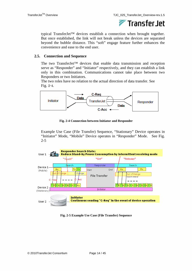
The two TransferJet™ devices that enable data transmission and reception serve as “Responder” and “Initiator” respectively, and they can establish a link only in this combination. Communications cannot take place between two Responders or two Initiators. The two roles have no relation to the actual direction of data transfer. See Fig. 2-4.
Fig. 2-4 Connection between Initiator and Responder
Example Use Case (File Transfer) Sequence, “Stationary” Device operates in “Initiator” Mode, “Mobile” Device operates in “Responder” Mode. See Fig. 2-5
Fig. 2-5 Example Use Case (File Transfer) Sequence

TransferJetTM Overview TJC_025_TransferJet_Overview-rev.1.5
© 2010TransferJet Consortium Page 15 / 45
2.6. Specification Details
TransferJet™ Specifications consist of the following three Layers. ・ Physical Layer (PHY) ・ Connection Layer (CNL) ・ Protocol Conversion Layer (PCL)
Layer 5Session
Layer 4Transport
Layer 3Network
Layer 2Data Link
Layer 1Physical
Layer 6Presentation
Layer 7Application
Provides human users, as well as otherprograms, with various services that use datacommunication.
Converts data received from Layer 5 to a formatunderstandable to the user or data sent from Layer7 to a format suitable for data communication.
Establishes or releases a virtual path(connection) for communication programs toexchange data.
Performs data compression, error correction,retransmission control, etc. to ensure secureand efficient data delivery to the destination.
Selects a communication path to deliver data tothe destination and manages addresses withinthe communication path.
Secures a physical communication path to thedestination and detects and corrects errors inthe data flowing along the path.Responsible for electrical conversion and othermechanical tasks needed to send data overcommunication lines. Pin shapes, cablecharacteristics, and others are defined by Layer 1.
Layer 2, Layer 4
TransferJet is P2P communicationso there is no Layer 3
Layer 1PHY
Layer 6 - Layer 7
PCLLayer 5
USER APPLICATION
CNLTransferJet is P2P communication
so there is no Layer 3
Fig. 2-6 TransferJet™ Layer Model and OSI Layer Model

TransferJetTM Overview TJC_025_TransferJet_Overview-rev.1.5
© 2010TransferJet Consortium Page 16 / 45
3. Architecture and Hierarchy
The Physical layer, or PHY, defines the actual radio. This layer converts the digital information into an RF signal suitable for transmission across the TransferJet™ couplers. The Connection Layer, or CNL, manages the connection and data delivery. For connection management the CNL is responsible for establishing and releasing the connection to a peer TransferJet™ device. For data delivery, the CNL provides packets to carry the data payload and confirm successful delivery of those packets to the peer device. The Protocol Conversion Layer, or PCL, is responsible for converting from an Application’s existing interface standards (such as SCSI or OBEX), and the TransferJet™ native protocol. In this way, for example, a stationary device can access data on a mobile device without modification to the application layer software. There is also a separate Application Management Layer (not defined in Rev. 1.0) that coordinates and manages the applications, as well as guidelines that define how devices should provide feedback to inform the user of the progress of a transfer operation.
Fig. 3-1 Hierarchical structure of TransferJet™ Stack
3.1. Physical Layer Overview
During transmission, the Physical Layer (PHY) receives the digital data stream from the upper Connection Layer (CNL) and converts to an analog RF signal centered at 4.48 GHz, which feeds the induction coupler element. The PHY data packets are structured in the form of Service Data Units (PSDU) separated by inter-frame spaces (IFS). The PSDU starts with a preamble, sync and header followed by a variable-length payload that can typically last about 2 msec. The PSDU applies forward error correction (FEC), spreading, scrambling and modulation together with multirate support capability. The modulation used is direct sequence spread spectrum (DS-SS). Complicated schemes such as OFDM are not needed since, unlike traditional wireless systems, the point-to-point proximity connection does not suffer from instabilities arising from reflections or interference. The transmitted RF power level is controlled such that it will not exceed -70 dBm. During reception, the PHY performs the reverse operations to convert the RF signal from the coupler into a digital data stream that can be handled by the upper CNL.
Defined in Rev.1.0
Not defined
in Rev.1.0
PCL
Layer

TransferJetTM Overview TJC_025_TransferJet_Overview-rev.1.5
© 2010TransferJet Consortium Page 17 / 45
In conjunction with the special coupler optimized for the transmission and reception of longitudinal electric induction waves and having a sharp spatial attenuation characteristic, the PHY is designed to achieve excellent close proximity data transfer operating at a separation distance that is well below 1/2 wavelength at the carrier frequency.
3.2. Modulation Scheme
Table 3-1 shows the PHY modulation parameters of this system. For the modulation scheme, the system employs Pi/2 shift BPSK at a chip rate (Rc) of 560 Mcps. Here, the chip rate refers to the bandwidth occupied on the frequency axis, while the reciprocal of the chip rate (1/Rc) represents the interval between samples of the envelope concatenated along the time axis. Since the system utilizes Pi/2 shift BPSK for the modulation, the occupied bandwidth (Rs) on one channel (Ich or Qch) is half the bandwidth (Rc) of the envelope; hence, the relationship of Rs = 1/2Rc is established. Also, the system adopts a concatenated coding method using convolutional codes and Reed-Solomon codes for forward error correction (FEC).
Chip Rate: Rc 560 Mcps
Chip duration: Tc = 1/Rc 1.786 nsec
Symbol Rate: Rs 280 Msps
Carrier Center Frequency: F 4.48 GHz
Modulation Pi/2 shift BPSK + DSSS
FEC 1/2 Convolutional code + Reed Solomon code
Table 3-1 Tx Signal Specification
3.3. Frame Format
Fig. 3-2 shows the format of the packet frame used by this system. This figure expresses the case of 2 CSDUs in the CPDU. The CPDU frame from CNL is divided into 224-byte message blocks and RS (Reed-Solomon) parity is added after each 224-byte block. The size of the last message block will be 1 to 224 bytes as shown in Fig. 3-2. RS parity of the last message block is calculated by expanding the message size to 224 bytes with zero padding. The added zeros of the last block are not transmitted and will be recovered at the receiver. Convolutional encoding is applied to the output of the RS-encoder. The output length of the convolutional encoder will be doubled due to the R = 1/2 convolutional code. Tail bits which include all zero bits are added after the convolutional encoded data. These tail bits initialize the state of the Viterbi decoder in the receiver.

TransferJetTM Overview TJC_025_TransferJet_Overview-rev.1.5
© 2010TransferJet Consortium Page 18 / 45
Finally, the transmitter adds spreading, scrambling, and Pi/2 BPSK mapping to form the Tx packet payload. This payload is combined with the Preamble, Sync word, and PHY Header to complete the Tx packet.
Fig. 3-2 PHY and CNL Packet Structure
3.4. Connection Layer Overview
The main functions of the Connection Layer (CNL) consist of establishing, maintaining and releasing the connection, or data link, between the two devices, as well as ensuring the integrity of the data transfer. One CNL Protocol Data Unit (CPDU) contains headers, subheaders, CRC bits and either one or two payload, each having 1-4096 Bytes of data. In terms of functionality, the device that transmits the initial connection request is defined as the “initiator” while the device that responds and accepts the request is called the “responder”. These terms refer to the initial handshaking sequence and have no relation to the actual direction of user application data (which is bi-directional). The initiator may send out the request signals continuously or in specific moments. The responder search state can minimize power consumption by means of intermittent operation. In the rare event that there exists more than one device trying to establish a connection, the CNL will arbitrate the media access and select just one by means of random back-off. Since all connections are point-to-point, there is no network or IP layer in the protocol stack and the CNL exchanges data directly with the upper PCL (Layers 4 and 5).

TransferJetTM Overview TJC_025_TransferJet_Overview-rev.1.5
© 2010TransferJet Consortium Page 19 / 45
3.4.1. CNL state
The CNL has eight states and three sub-states to manage the connection as follows.
Table. 3-1 CNL states
State name Description
Close In this state, the CNL is not being activated.
Search This state is for waiting for the connection request
(C-Req).
Connection Request This state is for requesting a link establishment.
Accept Waiting This state is for waiting for the PCL response, after
receiving the C-Req from the initiator candidate.
Response Waiting This state is for waiting for the PCL response, after
receiving the C-Acc from the responder candidate.
Responder Response This state is for accepting a link connection.
Initiator Connected In this state, the CNL is being connected.
Responder Connected In this state, the CNL is being connected.
The Initiator Connected state and the Responder Connected state have the following sub-states.
Table. 3-2 CNL sub-states Sub-state name Description
Connected In this sub-state, Data CPDU can be exchanged.
Local Hibernate This sub-state is for performing hibernation while being
connected.
Target Sleep This state is used when it is assumed that the target is
hibernating and the own entity is not hibernating.

TransferJetTM Overview TJC_025_TransferJet_Overview-rev.1.5
© 2010TransferJet Consortium Page 20 / 45
Fig. 3-3 shows the CNL state transition.
Close
Search
AcceptWaiting
ResponseWaiting
ConnectionRequest
ResponderResponse
ResponderConnected
InitiatorConnected
CNL_INIT.requestCNL_CLOSE.request
CNL_CONNECT.request
C-Req is received
C-Acc is received
CNL_ACCEPT.request
CNL_RELEASE.requestor
T_Connect timer expiresor
C-Rls is received
CNL_ACCEPT.request
CNL_RELEASE.request
CNL_ACCEPT.response
CNL_RELEASE.requestor
C-Rls receive
ACK for C-Acc is received
C-Rls is receivedor
T_Accept timer expires
CNL_RELEASE.requestor
C-Rls is receivedor
T_Retry timer expires
C-Sleep is receivedor
T_Resend timer expires C-Wake is received
CNL_DATA.requestor
CNL_WAKE.request
ACK for C-Wake is receivedor
C-Wake is received
CNL_RELEASE.requestor
C-Rls is receivedor
T_Retry timer expires
Connectedsub-state
Target Sleepsub-state
Local Hibernatesub-state
CNL_POWERSAVE.request(If the power save service is supported)
CNL_POWERSAVE.request(If the power save service is supported)
Fig. 3-3 CNL state transition

TransferJetTM Overview TJC_025_TransferJet_Overview-rev.1.5
© 2010TransferJet Consortium Page 21 / 45
4. Protocol Conversion Layer Overview
The Protocol Conversion Layer provides the necessary control functions to enable basic communications with the upper layer as well as the adapter functions to map the lower CNL layer to the upper applications and system interfaces.
4.1. Protocol Conversion Layer Controller
The PCL Controller offers common services, such as initialization and basic communications (connection setup, connection release, and device authentication) to the Upper Layer. 4.1.1. Services
The PCL Controller provides the services (hereinafter called “PCLC Services”) described below, using the mechanisms provided by the CNL. Also the services composed of the PCLC Services and the services provided by PCL Adapter are hereinafter called “PCL Services”.
1. Connection Management service The PCL Controller provides a service that manages the establishment and release of a connection between two TransferJet™ devices. When two TransferJet™ devices enter the communication range, the service establishes a CNL connection, unless the Device Modes (see 4.1.2) of both devices are Reactive Mode.
2. Device Authentication service The PCL Controller provides a service for authenticating CNL-connected TransferJet™ devices. This device authentication is mutual.
3. Application-Service Control service This service provides a framework for CNL-connected TransferJet™ devices to determine the desired Application-Service (this is defined as a service provided by a pair of applications that each is executed on the TransferJet™ device). See 4.1.3 about Application-Service Parameter which is a combination of components necessary to determine the Application-Service.
4.1.2. Device Model and Device Modes
The PCL Controller supports the two types of use case described below, by working in conjunction with the Upper Layer.
a) After a specific application starts on one device, that device touches a peer device. The peer device selects and starts the protocol and application corresponding to the application running on the other device.
b) Two devices touch each other when no specific application has yet to start on either of them. Based on the priority relationship between the devices, the device with the higher priority starts an application. The other device

TransferJetTM Overview TJC_025_TransferJet_Overview-rev.1.5
© 2010TransferJet Consortium Page 22 / 45
with the lower priority selects and starts the protocol and application corresponding to the application started on the higher priority device.
To implement these two types of use case, TransferJet™ devices dynamically use the three modes described in Table 4-1. These are called the Device Modes. The table also shows the priority relationship among the Device Modes. Hereinafter, the device with the higher priority value is referred to as the High Priority Device, and the device with the lower priority value is referred to as the Low Priority Device.
Device Mode Device Mode
priority Description
Proactive Mode High
A device in this mode uses the Application-Service provided by the peer device.
Flexible Mode Middle
A device in this mode behaves differently depending on the mode of the peer device.
Reactive Mode Low
A device in this mode is standing by to provide its Application-Service at the request of the peer device.
Table 4-1 Device Mode Definition
Use case (a) corresponds to the combination of either a Proactive Mode device and a Reactive Mode device or a Proactive Mode device and a Flexible Mode device. Use case (b) corresponds to the combination of a Flexible Mode device and a Reactive Mode device. A CNL connection is successfully established even in the case of any other combination except the case between the both Reactive Mode devices, although the PCLC Services will not be executed. This is summarized in Table 4-2.
Proactive Flexible Reactive
Proactive N/A Use case (a) Use case (a)
Flexible Use case (a) N/A Use case (b)
Reactive Use case (a) Use case (b) -
Table 4-2 Relationship between Device Mode Combinations and Use Cases
4.1.3. Application-Service Parameter
The Application-Service Parameter is a combination of components necessary to determine the Application-Service to be provided by a pair of two

TransferJetTM Overview TJC_025_TransferJet_Overview-rev.1.5
© 2010TransferJet Consortium Page 23 / 45
TransferJet™ devices. Table 4-3 describes the components of this Application-Service Parameter.
Component Description
Protocol Communication protocol for data communication between the applications running on TransferJet™ devices.
Protocol Class Defines the protocol operation rule to ensure interconnectivity communication between the applications running on TransferJet™ devices. This parameter is dependent on Protocol.
Protocol Extension Defines a component necessary to determine an Application-Service that cannot be defined by Protocol and Protocol Class. This parameter is dependent on Protocol and Protocol Class.
Table 4-3 Application-Service Parameter
Protocol Class is a dependent concept of Protocol, and Protocol Extension is a dependent concept of Protocol and Protocol Class. An Application-Service is represented by the combination of Protocol, Protocol Class, and Protocol Extension. Fig. 4-1 shows the conceptual diagram of the Application-Service Parameter.
Fig. 4-1 Overview of Application-Service Parameter
A TransferJet™ device can start the desired Application-Service by the Upper Layer performing the following procedure via the PCL Controller.
1. Acquire the Application-Service Parameter list from the peer device.
2. Search Application-Services and determine the desired one, based on the Application-Service Parameter list acquired from the peer device.
3. Set the Application-Service Parameter corresponding to the desired Application-Service to the peer device.
This procedure allows an application to be executed that is associated with the Application-Service Parameter negotiated between the two TransferJet™ devices. In step 3, no more than one Application-Service Parameter can be set to a single TransferJet™ device at a time. Also, only a Proactive Mode Device can set an Application-Service Parameter to the peer device.
Protocol Class Protocol Protocol Extension

TransferJetTM Overview TJC_025_TransferJet_Overview-rev.1.5
© 2010TransferJet Consortium Page 24 / 45
4.1.4. PCL Controller Message
PCLC Messages are control messages that two PCL Controllers exchange after CNL connection establishment. They are used to implement the PCLC Services.
PCLC Messages are categorized into four types described in Table 4-4.
The basic PCLC Message exchange procedure begins when the device sends a Request Message and ends when the device receives a Response Message for the request. Fig. 4-2 shows the sequence of this typical case.
If the processing requested by the peer device takes time and a Response Message cannot be returned within a certain amount of time, the responding device sends a Pending Message to notify the peer device that the request is being processed. A Pending Message is sent repeatedly until a Response Message is returned. Fig. 4-3 shows the sequence of this typical case.
An Abort Message is a special message used to request that the PCL Services be stopped forcibly.
The Request Message and the Abort Message are sent from High Priority Device, and the Response Message and the Pending Message are sent from Low Priority Device.
PCLC Message Type Description
Request Message Message that requests the PCLC of the peer device to perform processing.
Response Message Message that is returned in response to a request from the PCLC of the peer device.
Pending Message Message that notifies the PCLC of the peer device that its request is being processed.
Abort Message Message that requests the PCLC of the peer device to abort the PCL Services.
Table 4-4 PCLC Message Type

TransferJetTM Overview TJC_025_TransferJet_Overview-rev.1.5
© 2010TransferJet Consortium Page 25 / 45
Fig. 4-2 Sequence That Applies When the Requested Processing Asked for the
Responding Side Is Completed within ResPeriod
Fig. 4-3 Sequence That Applies When the Requested Processing Asked for the
Responding Side Is Not Completed within ResPeriod
Requesting Side
Pending Message (PendingPeriod)
PendingPeriod
Total time
Responding Side
Action Request Message
ResPeriod
Action Response Message (Response Code)
…
Processing request
…
Pending Message (PendingPeriod)
Pending Message (PendingPeriod)
Requesting Side
Responding Side
Action Request Message
Processing request
Action Response Message
(Response Code)

TransferJetTM Overview TJC_025_TransferJet_Overview-rev.1.5
© 2010TransferJet Consortium Page 26 / 45
4.1.5. Overview Flow of PCL Controller
Fig. 4-4 shows overview flow in the typical case when the PCL Controller starts an Application-Service.
Fig. 4-4 Overview Flow When the PCL Controller Starts an Application-Service
• Connection: When two TransferJet™ devices are brought close together within the communication range, the PCL Controller establishes a CNL connection between the TransferJet™ devices.
• Authentication: When a CNL connection is successfully established, after exchanging device information (Vendor ID, Product ID, Product Class, Vendor Name, and Product Name) between CNL-connected TransferJet™ devices, the PCL Controller handles the exchange of PCL Controller Messages used to implement device authentication.
• Service Negotiation: When device authentication is successful, the TransferJet™ device starts an Application-Service by the Upper Layer getting the Application-Service Parameter list and setting an Application-Service Parameter via the PCL Controller.
• Service Execution: When an Application-Service successfully starts, an Application-Service is executed.
TransferJet Device A
Connection
TransferJet Device B
Device Authentication
Service Negotiation
Service Execution

TransferJetTM Overview TJC_025_TransferJet_Overview-rev.1.5
© 2010TransferJet Consortium Page 27 / 45
4.1.6. PCL Controller state
The PCL has three states (Unconnected/Connecting/Connected) and four sub-states (Authentication/Negotiating/Executing Service/No Service) to manage PCL connection.
Fig. 4-5 shows the PCL Controller state transition.
Fig. 4-5 PCL Controller state transition
Unconnected
Connecting
Authenticating
Negotiating
No Service
Executing Service
Connected
Device authentication failure or Abort
PCL negotiation success / Start Application-Service
PCL negotiation failure or Abort Device authentication
success Stop service request or Abort
/ Stop Application-Service
CNL connection established [Device mode is different]
Receive C-Req or C-Acc
CNL connection down / Stop Application-Service if running
CNL connection established [Device mode conflict]

TransferJetTM Overview TJC_025_TransferJet_Overview-rev.1.5
© 2010TransferJet Consortium Page 28 / 45
4.2. Overview of OBEX Application and Adapter
PCL OBEX is a type of PCL Adapter that handles transparent user data transmission to the peer PCL OBEX. Only one connection is supported by PCL OBEX, and only the OBEX protocol is the allowable upper layer user. PCL OBEX consists of OBEX Server and OBEX Client, which have the same service and function to the user. Thus, they are not distinctively mentioned in the following descriptions. PCL Controller activates the PCL OBEX entity after TransferJet™ inter-device connection establishment and adapter type negotiation. Fig.4-6 shows the protocol stack including PCL OBEX.
OBEX Protocol (Client)
PCL OBEX
CNL
Application
OBEX Protocol (Server)
PCL OBEX
CNL
Application
PCL Controller
PCL Controller
PHY PHY
Fig.4-6 PCL OBEX Protocol Stack
The "Protocol Class" mentioned here describe the operation rules for the OBEX protocol specification used by the applications. Protocol Class is determined taking into account such factors as the TransferJet™ characteristics, expected use cases, functions, and implementation cost. TransferJet™ Version 1.0 defines the following two basic Protocol Classes for the OBEX applications. "Push Protocol Class" This class allows the client to put an arbitrary file to the server. It is based on the Inbox Service described in IrDA Object Exchange Protocol Ver.1.4. "File Transfer Protocol Class" This class supports file transfer and file/folder operation capabilities equivalent to those of FTP.

TransferJetTM Overview TJC_025_TransferJet_Overview-rev.1.5
© 2010TransferJet Consortium Page 29 / 45
It is based on the Folder Browsing Service described in IrDA Object Exchange Protocol Ver.1.4.
4.2.1. Format of Protocol Data Unit
OBEX PCL PDU has no additional information such as header or padding. The maximum PCL OBEX PDU and PCL OBEX SDU sizes are the same as that of an OBEX packet defined for the OBEX protocol. Fig. 4-7 shows the OBEX protocol layer, PCL OBEX, and inter-layer data flow in CNL. The user data of the OBEX protocol (OBEX packet) is mapped to a PCL OBEX SDU one to one. PCL OBEX delivers PCL OBEX PDU to CNL in user data transmission. CNL divides it into CSDUs to generate CPDUs. To indicate the end of the PCL OBEX PDU, the More Fragment Bit of the final CPDU is set to 0. In user data reception, CNL connects those up to the CSDU with More Fragment Bit 0 in the same manner and passes it to PCL OBEX. PCL OBEX passes the PCL OBEX SDU to the OBEX protocol layer.
User Data (OBEX Packet)
PCL OBEX SDU
PCL OBEX PDU
CSDU CSDU … CSDU
OBEX Protocol
Layer
PCL OBEX
CNL
Transport Block
CPDU CPDU … CPDU
More Fragment: 1 More Fragment: 1 More Fragment: 0
Fig. 4-7 Data Flow for PCL OBEX

TransferJetTM Overview TJC_025_TransferJet_Overview-rev.1.5
© 2010TransferJet Consortium Page 30 / 45
4.2.2. Sequence
Fig. 4-8 shows an example of the data transmission sequence. PCL OBEX receives the start request PCL_OBEX_START.request from PCL Controller after TransferJet™ connection establishment and starts operating. After that, user data is transferred to/from the OBEX protocol layer with PCL_OBEX_DATA.request/ PCL_OBEX_DATA.indication until the stop request PCL_OBEX_STOP.request is received from PCL Controller.
OBEX
Protocol Layer
(Client)
PCLControllerPCL OBEX PCL OBEXCNL CNL
PCL_OBEX_DATA.request CNL_DATA.request(Profile ID:1)
Data(More Fragment:1)
CNL_DATA.indication(Profile ID:1)
PCL_OBEX_DATA.indication
PCL Controller
OBEX Protocol
Layer(Server)
PCL_OBEX_START.request
Data(More Fragment:1)
Data(More Fragment:0)
PCL_OBEX_DATA.requestCNL_DATA.request(Profile ID:1)
PCL_OBEX_START.request
Data(More Fragment:0)CNL_DATA.indication(Profile ID:1)
PCL_OBEX_DATA.indication
PCL_OBEX_STOP.request PCL_OBEX_STOP.reque
st
TransferJet Connection Establishment and Negotiation of PCL Adapter Type
Continue OBEX Session
OBEX Protocol Processing
Disconnect TransferJet Connection
Fig. 4-8 Example of PCL OBEX sequence

TransferJetTM Overview TJC_025_TransferJet_Overview-rev.1.5
© 2010TransferJet Consortium Page 31 / 45
4.3. Overview of SCSI Application and Adapter
PCL SCSI is a PCL Adapter that enables I/O operations between devices which support SCSI protocol. According to the SCSI protocol, the devices work as a SCSI Initiator or SCSI Target.
There is only one application client in the SCSI Initiator, single or multiple logical units in the SCSI Target. PCL SCSI maintains only one I_T nexus on TransferJet™ connection. Fig. 4-9 shows a protocol stack including PCL SCSI.
PCLController
PCL SCSI
CNL
PHY
PCLController
PCL SCSI
CNL
PHY
SCSI Initiator SCSI Target
Application client
Application
Logical unit
Application
Fig. 4-9 PCL SCSI Protocol Stack
PCL SCSI defines the following Protocol Classes for SCSI applications which are meant to provide interoperability between an application client in the SCSI Initiator and a logical unit(s) in the SCSI Target. The Protocol Class is determined taking into consideration such factors as the TransferJetTM characteristics, expected use cases, functions, and implementation costs. "Block Device Class" This Protocol Class is used to communicate between an application client and a logical unit(s) supporting SCSI Block Commands. This Protocol Class has the following two types of Protocol Class according to the device role of SCSI (Initiator/Target). Block Device Class - Target Block Device Class - Initiator
"Block Device Class + SD-SCSI Pass-Through" This Protocol Class is used to communicate between an application client and a logical unit(s) supporting SCSI Block Commands and SD-SCSI Pass-Through Commands. The SD-SCSI Pass-Through Commands can be utilized to transfer arbitrary SD commands over “SD Command over SCSI Protocol” specified in

TransferJetTM Overview TJC_025_TransferJet_Overview-rev.1.5
© 2010TransferJet Consortium Page 32 / 45
the TransferJet specifications. This Protocol Class has the following two types of Protocol Class according to the device role of SCSI (Initiator/Target). Block Device Class + SD-SCSI Pass-Through - Target Block Device Class + SD-SCSI Pass-Through - Initiator
4.3.1. SCSI Implementations over TransferJet™
A SCSI Command is executed by transferring PCL SCSI PDU into which SCSI Command, SCSI Data (in/out) or SCSI Command Response is encapsulated.
To execute the SCSI Command, PCL SCSI defines two types of PDU, which are PDU of SCSI Command and PDU of SCSI Command Response. In the case of SCSI Command with data-in transfer, SCSI Data is included in the PDU of SCSI Command Response. In the case of SCSI Command with data-out transfer, SCSI Data is included in the PDU of SCSI Command. (See PCL SCSI Adapter Specification for the other types of PDU)
The data flow between PCL SCSI and CNL is shown below.
PCL SCSI
CNL
PCL SCSI PDU
Transport Block
CSDU CSDU・・・
CPDU
CSDU
CPDU
CSDU
CPDU CSDU・・・
More Fragment :1 More Fragment :1 More Fragment :1 More Fragment :0
Fig. 4-10 Data flow of PCL SCSI If the length of PCL SCSI PDU is greater than the maximum length of CSDU, the PCL SCSI PDU is divided into CSDUs, and CPDUs corresponding to each CSDU are created. When the CSDU is not the last one to be transmitted from a given PDU, then the CPDU whose More Fragment is set to ‘1’ is transmitted. When the CSDU is the last one to be transmitted, the CPDU whose More Fragment is set to ‘0’ is transmitted. When a CPDU whose More Fragment is set to ‘0’ is received, it means that the PCL SCSI PDU has been received.

TransferJetTM Overview TJC_025_TransferJet_Overview-rev.1.5
© 2010TransferJet Consortium Page 33 / 45
4.3.2. SCSI Command execution sequence
4.3.2.1. Sequence of SCSI Command without data transfer
Fig. 4-11 shows an example of sequence of SCSI Command without data transfer.
Fig. 4-11 Sequence of SCSI Command without data transfer
SCSI Initiator sends a PDU of SCSI Command to execute the SCSI Command. When the PDU has been received, SCSI Target sends a PDU of SCSI Command Response after the SCSI Command is completed.
Application Client
PCL SCSI
PCL SCSI
Logical Unit
SCSI Initiator SCSI Target
Request to execute SCSI Command
CNL /PHY
CNL /PHY
Request to send PDU of SCSI Command
CPDU (MF*=0)
Executing the SCSI Command
CPDU (MF*=0)
Notify a reception of PDU
Notify that the SCSI Command has been completed.
Notify a reception of PDU Notify the SCSI
Command
Request to return SCSI Command Response
Request to send PDU of SCSI Command Response
*MF=More Fragment

TransferJetTM Overview TJC_025_TransferJet_Overview-rev.1.5
© 2010TransferJet Consortium Page 34 / 45
4.3.2.2. Sequence of SCSI Command with data-in transfer
Fig. 4-12 shows an example of sequence of SCSI Command with data-in transfer.
Fig. 4-12 Sequence of SCSI Command with data-in transfer
SCSI Initiator sends a PDU of SCSI Command to execute the SCSI Command. When the PDU has been received, SCSI Target executes the SCSI Command and obtains SCSI Data from Device Server. After the SCSI Command is completed, SCSI Target sends a PDU of SCSI Command Response including the SCSI Data.
Application Client
PCL SCSI
PCL SCSI
Logical Unit
SCSI Initiator SCSI Target
Request to execute SCSI Command
CNL /PHY
CNL /PHY
Request to send PDU of SCSI Command
CPDU (MF*=0)
Executing the SCSI Command
CPDU (MF*=1)
Notify a reception of PDU
Notify that the SCSI Command has been completed.
Notify a reception of PDU Notify the SCSI
Command
Request to return SCSI Command Response
Request to send PDU of SCSI Command Response
CPDU (MF*=1)
CPDU (MF*=1)
CPDU (MF*=0)
・・・
Obtain Data from Device Server
Request to send Data.
CPDU (MF*=1)
*MF=More Fragment

TransferJetTM Overview TJC_025_TransferJet_Overview-rev.1.5
© 2010TransferJet Consortium Page 35 / 45
4.3.2.3. Sequence of SCSI Command with data-out transfer
Fig. 4-13 shows an example of sequence of SCSI Command with data-out transfer.
Fig. 4-13 Sequence of SCSI Command with data-out transfer
SCSI Initiator sends a PDU of SCSI Command including SCSI Data to execute the SCSI Command. When the PDU has been received, SCSI Target executes the SCSI Command, retrieves SCSI Data from the PDU and delivers the SCSI Data to Device Server. After the SCSI Command is completed, SCSI Target sends a PDU of SCSI Command Response.
Application Client
PCL SCSI
PCL SCSI
Logical Unit
SCSI Initiator SCSI Target
Request to execute SCSI Command
CNL /PHY
CNL /PHY
Request to send PDU of SCSI Command
CPDU (MF*=1)
Executing the SCSI Command
CPDU (MF*=1)
Notify a reception of PDU
Notify that the SCSI Command has been completed.
Notify a reception of PDU Notify the SCSI
Command
Request to return SCSI Command Response
Request to send PDU of SCSI Command Response
CPDU (MF*=1)
CPDU (MF*=0)
Deliver Data to Device Server
Retrieve Data from PDU of SCSI Command
CPDU (MF*=0)
・・・
CPDU (MF*=1)
*MF=More Fragment

TransferJetTM Overview TJC_025_TransferJet_Overview-rev.1.5
© 2010TransferJet Consortium Page 36 / 45
4.3.3. Requirements for logical unit
Requirements for logical unit are as follows: - Includes only block devices (defined in SBC) in device server. - Auto Contingent Allegiance (defined in SAM2) is not established. - Linked command (defined in SAM2) execution is not permitted. - All block devices included in logical unit is recommended to be
write-protected. - Asynchronous Event Reporting (defined in SAM2) is not supported. - Task manager (defined in SAM2) in logical unit is required to detect
overwrapped commands (defined in SAM2).
In addition, logical unit has limitation below as default: - No command queuing of any kind supported.
Command queuing may be enabled to a logical unit.

TransferJetTM Overview TJC_025_TransferJet_Overview-rev.1.5
© 2010TransferJet Consortium Page 37 / 45
5. Certification Program
One important activity of TransferJet Consortium is taking the TransferJet™ Specifications and verifying compliance by developing and implementing testing procedures. As one such activity, TransferJet Consortium administers the TransferJet™ Certification Program – designed to test and certify the technical design and basic interoperability of products and components utilizing TransferJet™ technology. Basic Concepts Compliance Components
Compliance is comprised of Conformance and Interoperability. Conformance ensures that a product utilizing TransferJet™ technology correctly implements the technical specifications. Interoperability ensures that products utilizing TransferJet™ technology are able to communicate and operate correctly with each other as defined in the technical specifications.
Compliance Testing Compliance Testing is composed of a set of individual tests to verify compliance of products with the technical specifications. The test items and procedures are described in the following two documents. Conformance Test Specification (CTS) Interoperability Test Specification (ITS)
Certification
Certified Product means that Compliance of the product has been verified by passing the Certification Program which includes Compliance Testing. Certification is not a warranty or guarantee of any kind by the Consortium but is a statement that the certified product has successfully passed the prescribed set of testing under a specific set of test conditions.
Product Types
Products which can be submitted to the Certification Program are categorized into the following types.
End Product: products designed to be used by End Users (consumers). There are two types of End Products. Complete End Product: End Product in which all the mandatory layers of the TransferJet protocol stack are implemented. Partial End Product: End Product in which some of the mandatory layers of the TransferJet protocol stack are not implemented within itself but, by combining with another Partial End Product, will together comprise a system such that all the mandatory layers of TransferJet protocol stack are implemented. Component Product: products designed to be embedded into an End Product which will then comprise a complete TransferJet protocol stack.

TransferJetTM Overview TJC_025_TransferJet_Overview-rev.1.5
© 2010TransferJet Consortium Page 38 / 45
Qualified Test Laboratory Qualified Test Laboratory (QTL) is a facility which is officially accredited by the Consortium to provide testing services, and is equipped with appropriate test systems and operated by trained operators who perform the Compliance Tests.
Certification Processes
Certification Processes are the set of procedures established and performed by the Consortium, Consortium Members, and QTL to issue and maintain Certification. Certification Processes consist of the following:
Primary Certification Process: the fundamental process to issue Certification to an original, basic product Certification Amendment Process: the process to amend an existing Certification. Derivative Certification Process: the process to certify additional products that contain only Non-TransferJet Changes and/or Alternative Component Replacements. External Change Process: the process to certify additional products that contain only External (non-functional) Changes. Version-Up Certification Process: the process to certify TransferJet Implementation Change. Rebranding Certification Process: the process to transfer a certification from one member company to another, for cases of OEM/Rebranding. Test Case Waiver Process: the process to waive a Required Test Case in case there is a fault in Technical Specifications and/or Test Specifications with respect to the Test Cases. Product Change Assessment Process: the process of reviewing with the Consortium about defining and approving allowed Product Changes.

TransferJetTM Overview TJC_025_TransferJet_Overview-rev.1.5
© 2010TransferJet Consortium Page 39 / 45
6. Trademark and Logo
TransferJet Consortium defines the usages of the TransferJet trademark and logos to establish and maintain a consistent Visual Identity (VI) and brand awareness in the market and to ensure correct and consistent messaging to the users.
About the TransferJet Logo
Usage on Products and Literature The use of TransferJet logos is allowed individually to products and literature that have demonstrated their compliance with TransferJet™ specifications. Details on licensing are specified in the Certification Program (including compliance testing) administered by TransferJet Consortium.
Usage for Other Purposes The TransferJet logos can also be used for promoting the TransferJet concept, technology, usage models, specifications or certified products.
Usage by Non-Members of TransferJet Consortium Approval is required by TransferJet Consortium in case non-members desire to use the TransferJet logos for whatever purpose.
Types of TransferJet Logos There are three types, as shown below.
Brand Logo
Symbol Logo
Target Point Logo
The brand logo and symbol logo shall be used to represent TransferJet™ products. The target point logo shall be used to denote the place where the products should be touched, typically aligned with the center of the coupler.

TransferJetTM Overview TJC_025_TransferJet_Overview-rev.1.5
© 2010TransferJet Consortium Page 40 / 45
About the Target Point Logo The target point logo shall be displayed on all TransferJet™ products. The target point logo is used to inform the users about the location where the products should be touched. Therefore, it should be displayed visibly and clearly, and placed where it is easy for users to touch.

TransferJetTM Overview TJC_025_TransferJet_Overview-rev.1.5
© 2010TransferJet Consortium Page 41 / 45
7. What is the TransferJet Consortium?
The TransferJet Consortium was established by a group of international companies in July 2008 and has been registered as a General Incorporated Association in Japan since September 2011. The TransferJet Consortium focuses on the development of the specifications, compliance testing processes, certification program, as well as conduct marketing activities to promote the TransferJet™ technology, products, applications and services across industries and to consumers. Through these initiatives, the TransferJet Consortium aims to create, support and expand the market for TransferJet™ products.
8. TransferJet Consortium Goals
TransferJet Consortium has the common goal of developing the technology, products and services based on "TransferJet" wireless technology.
(1) Development of the specifications of TransferJet™ wireless technology (2) Development of compliance testing processes and tools (3) Management of the certification program (4) Promotion of the TransferJet™ technology, concept and usage models
9. TransferJet Consortium Organizational Structure and Working Groups
The organization consists of a Management Meeting and three Working Groups, as shown in Fig. 9-1. In addition, there are Task Forces and other sub-groups that are formed at various times to address specific issues. Promoter company members participate in the Working Group activities. The purpose and scope of activity of each Working Group are as follows:
Fig. 9-1 TransferJet Consortium Organization
Technical Working Group [Purpose] Create and maintain the TransferJet™ technical specifications and implementation guidelines [Scope] Evaluate the approved use cases and develop technical requirements for the creation of the specifications and guidelines. Develop specifications covering the TransferJet™ physical layer, connection layer and protocol conversion layers to satisfy the above technical requirements. Coordinate and collaborate with other

TransferJetTM Overview TJC_025_TransferJet_Overview-rev.1.5
© 2010TransferJet Consortium Page 42 / 45
Working Groups, as required. (Technical work related to compliance testing and certification will be addressed by the Compliance Working Group). Compliance Working Group [Purpose] Develop and maintain the necessary policies, test tools, infrastructure and program for members to validate correct implementation and operation of their products in accordance with the TransferJet™ specifications and guidelines. [Scope] ・ Develop and maintain the test specifications for the technical specifications and the implementation guidelines published by the Technical Working Group ・ Establish and execute policies and procedures for certification and enforcement of compliance with the technical specifications, the implementation guidelines and the test specifications ・ Work with test equipment vendors and test laboratory operators to develop equipment and laboratories for the certification procedures ・ Work with the marketing Working Group to resolve radio wave regulatory issues worldwide ・ Organize testing events for the consortium member companies to improve interoperability of their products ・ Disclose results of certification of compliance and keep documents Marketing Working Group [Purpose] Compile and analyze use cases, execute strategies to globally promote and raise awareness of the TransferJet™ concept and technology, including proper usage of the TransferJet™ logo and trademarks. [Scope] ・ Develop and execute strategies to globally promote and raise awareness of the TransferJet™ concept and technology to the industry and consumers ・ Execute proper usage of the TransferJet™ logo and trademarks ・ Participate in domestic and foreign marketing/PR events ・ Operate and maintain the contents of the TransferJet™ public website

TransferJetTM Overview TJC_025_TransferJet_Overview-rev.1.5
© 2010TransferJet Consortium Page 43 / 45
10. Membership
Members list is shown at the below link. http://www.transferjet.org/about_cons/index.html

TransferJetTM Overview TJC_025_TransferJet_Overview-rev.1.5
© 2010TransferJet Consortium Page 44 / 45
11. Abbreviations and Acronyms
ANSI American National Standards Institute Application-Service Service provided by a pair of applications that each
is executed on the TransferJet™ device Application-Service Control Service
Service which provides procedure for acquiring a list of the Application-Service Parameters available on the peer device, and procedure for setting the Application-Service Parameter to the peer device to request execution of the desired application corresponding to the Application-Service as the framework. However 、 detailed algorithm for determining a specific application using the Application-Service Parameter is not included in this service.
Application-Service parameter Combination of components necessary to determine the Application-Service
BPSK Binary Phase Shift Keying CNL CoNnection Layer CPDU Connection layer Protocol Data Unit CRC Cyclic Redundancy Check CSDU Connection layer Service Data Unit FEC Forward Error Collection IrDA Inferred Data Association MUX Multiplexer OBEX OBject EXchange PCL Protocol Conversion Layer PCLC PCL Controller PCLC Services Services provided by PCL Controller PCL Services PCLC services and services provided by PCL
Adapter PDU Protocol Data Unit PSD Power Spectral Density PSDU Phy layer Service Data Unit SAM2 SCSI-3 Architecture Model-2 SBC SCSI Block Commands SCSI Small Computer System Interface SDU Service Data Unit Service Function provided to the outside of a layer SPC2 SCSI Primary Commands-2 SRM Single Response Mode UWB Ultra Wide Band

TransferJetTM Overview TJC_025_TransferJet_Overview-rev.1.5
© 2010TransferJet Consortium Page 45 / 45
12. References
TransferJet™ PHY-CNL Specifications Version 1.2 TransferJet™ Specifications for Protocol Conversion Layer OBEX Adapter Version 1.0 TransferJet™ Specifications for Protocol Conversion Layer SCSI Adapter Version 1.1 TransferJet™ Specifications for Protocol Conversion Layer Controller Version 1.0 TransferJet™ Specifications for SCSI Application: SD Protocol over SCSI Protocol Version 1.0 TransferJet™ Protocol Class Specification for OBEX Application Version 1.0 TransferJet™ Protocol Class Specification for SCSI Application Version 1.1 TransferJet™ PCL Number Assignment Manual Version 1.2 TransferJet™ Unique ID Allocation Manual Revision 1.1 TransferJet™ Certification Program Reference Document Revision 1.0 TransferJet™ Test Case Reference Document Revision 1.2 TransferJet™ Conformance Test Specification Part 1 PHY/CNL Test Revision 1.1 TransferJet™ Conformance Test Specification Part 2 PCL Test Revision 1.0 TransferJet™ Interoperability Test Specification Revision 1.0 TransferJet™ Test Laboratory Management Document Revision 1.0 TransferJet™ Trademark Guideline Revision 1.3 TransferJet™ User Interface Guideline Revision 1.1 TransferJet™ Overview Whitepaper Spring 2009 IrDA Object Exchange Protocol Version 1.4 (July 27, 2007) ANSI INCITS 366-2003(R2008) SCSI-3 Architecture Model-2 ANSI INCITS 306-1996(R2008) SCSI Block Commands ANSI INCITS 351-2001 SCSI Primary Commands-2
Note : TransferJet specification is a part of ISO/IEC standards. (ISO/IEC-17568)
13. Qualified Test Laboratory (as of August 2015)
Allion Labs, Inc. http://www.allion.com/