transfer line calculations
DESCRIPTION
Transfer Line Calculations. 9-March-2009 and following. Input. 24 DCOPS, with 2 (averaged) values per PG positions of the DCOPS wrt their disk centers Ideal SLM directions Ideal Z positions of DCOPS. Verify. DCOPS PG Z on ME+2/3 agree with ideal Z differences. Unknowns. - PowerPoint PPT PresentationTRANSCRIPT
Transfer Line Calculations
9-March-2009
and following

Input
• 24 DCOPS, with 2 (averaged) values per
• PG positions of the DCOPS wrt their disk centers
• Ideal SLM directions
• Ideal Z positions of DCOPS

Verify
• DCOPS PG Z on ME+2/3 agree with ideal Z differences

Unknowns
• 3 disks (x,y) and RZ 9 unknowns
• 6 lasers (sx,sy) 12 unknowns
• 24 dV (?) 24 unknowns at 3.8T (0 at 0)
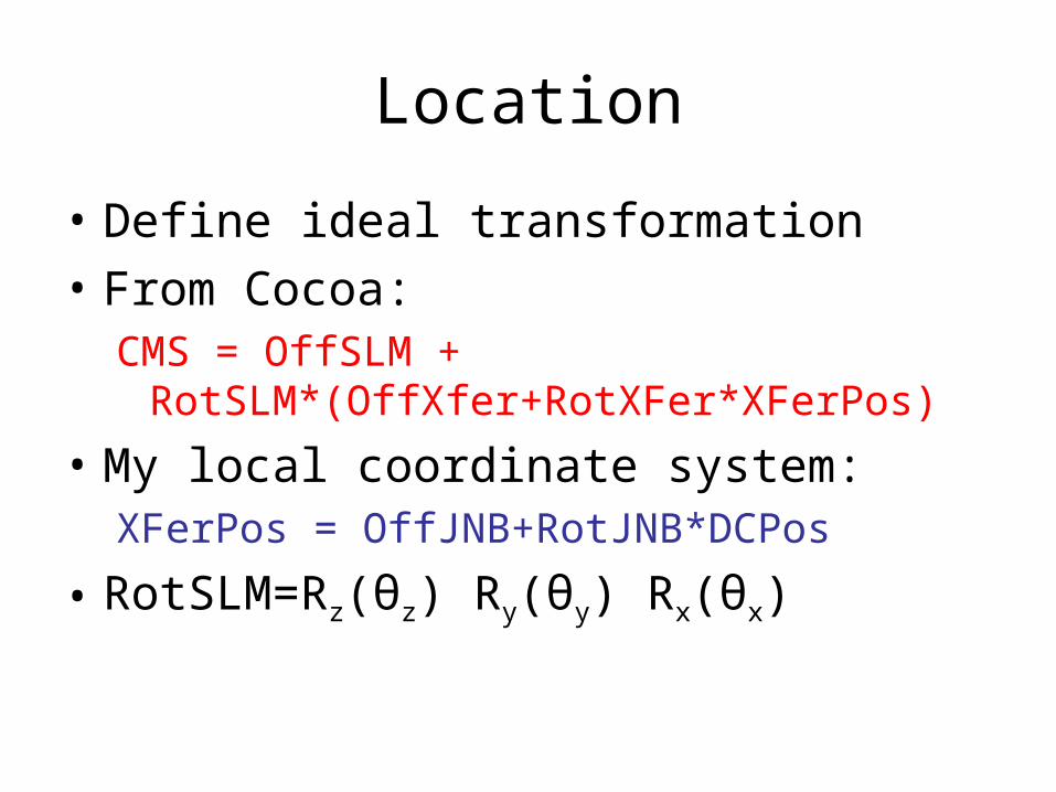
Location
• Define ideal transformation
• From Cocoa:CMS = OffSLM +
RotSLM*(OffXfer+RotXFer*XFerPos)
• My local coordinate system:XFerPos = OffJNB+RotJNB*DCPos
• RotSLM=Rz(θz) Ry(θy) Rx(θx)
Stations
• ME+1 and ME+2 face the same direction
• ME+3 and ME+4 face the same direction

ME+1 SLM transforms to CMS
X Y Z Rx Ry Rz
HSLM1 -17.0821 63.7511 6782 -90 0 15
HSLM2 -63.7511 17.0821 6782 -90 0 75
HSLM3 46.6690 46.6690 6782 -90 0 135
HSLM4 -17.0821 63.7511 6782 -90 0 195
HSLM5 63.7511 -17.0821 6782 -90 0 255
HSLM6 46.6690 46.6690 6782 -90 0 315
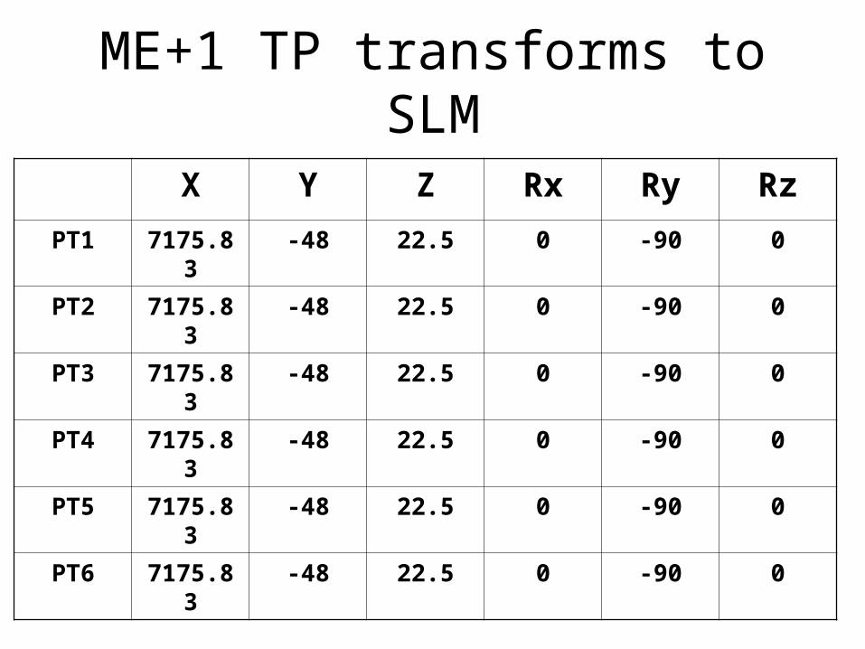
ME+1 TP transforms to SLM
X Y Z Rx Ry Rz
PT1 7175.83 -48 22.5 0 -90 0
PT2 7175.83 -48 22.5 0 -90 0
PT3 7175.83 -48 22.5 0 -90 0
PT4 7175.83 -48 22.5 0 -90 0
PT5 7175.83 -48 22.5 0 -90 0
PT6 7175.83 -48 22.5 0 -90 0

ME+2 SLM transforms to CMS
X Y Z Rx Ry Rz
SLM1 -77.64571 289.7777 7998 -90 0 15
SLM2 289.7777 -77.64571 7998 -90 0 75
SLM3 -212.132 -212.132 7998 -90 0 135

ME+2 TP transforms to SLMX Y Z Rx Ry Rz
TP1/S1 7175.829 -48 -22.5 0 90 0
TP4/S1 -7175.833 -48 22.5 0 -90 0
TP2/S2 -7175.829 -48 -22.5 0 90 0
TP5/S2 7175.833 -48 22.5 0 -90 0
TP3/S3 7175.829 -48 22.5 0 -90 0
TP6/S3 -7175.833 -48 -22.5 0 90 0

ME+3/4 SLM transforms to CMS
X Y Z Rx Ry Rz
SLM1 -77.64571 289.7777 9642/
10537
90 0 15
SLM2 289.7777 -77.64571 9642/
10537
90 0 75
SLM3 -212.132 -212.132 9642/
10537
90 0 135
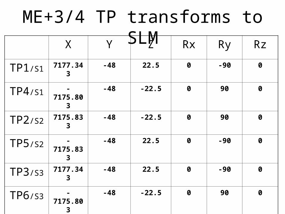
ME+3/4 TP transforms to SLMX Y Z Rx Ry Rz
TP1/S1 7177.343 -48 22.5 0 -90 0
TP4/S1 -7175.803 -48 -22.5 0 90 0
TP2/S2 7175.833 -48 -22.5 0 90 0
TP5/S2 -7175.833 -48 22.5 0 -90 0
TP3/S3 7177.343 -48 22.5 0 -90 0
TP6/S3 -7175.803 -48 -22.5 0 90 0

Local DCOPS/XFER coordinate
• X = rφ, phi in x y direction
• Y = R, radial
• Z “into page” using right hand rule
• X=Y=0 = center of DCOPS in ideal system
• Z=0 = position of Ref DCOPS dowel

Nomenclature (Z always ideal)
• (δx, δy) = shift in disk from ideal
• (H,V) = center of DCOPS wrt ideal, PG
• (ΔH, ΔV) = shift in local DCOPS center
• (PH,PV) = Profile predictions
• (0, dV) = cantilevered shift due to bending
• Indexed by station or disk and by point #

XFer Plate details
• Ref DCOPS dowel pin is X,Z center of XFer
• Ref DCOPS dowel is +6.724 shimmed away from Y center of XFer
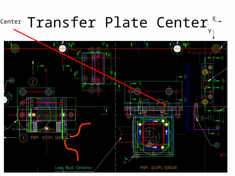
Transfer Plate CenterCenter
Y
X

Transform Center to XFer
X (=H) Y Z (=-V)
PT1 208.5 0 73.175
PT2 202.5 0 73.175
PT3 -157.5 0 73.175
PT4 -163.5 0 73.175
PT5 208.5 0 73.175
PT6 202.5 0 73.175
Rx=-90 Ry=0 Rz=0

Disk and PT: DCOPS to CMS: B=0
• C = XC + RC(XT+RT(XD+RD P)• C = XA + RA P• XA ≡ XC +RCXT+ RCRT XD
• RA ≡ RCRTRT
• Above are Ideal positions, XT from PG• Shifting (per disk) gives unknown (to be solved
for):• C’ = XS + RS C• RS mostly rotation about Z
Complications w/ B=3.8
• The disks bend– Bending is not the same at every PT– Cannot assume each disk bends the same
amount– ME+2/ME+3 cantilever by the same angle in
different directions
• Disks have additional rotation about Y (actually about line near the floor)

Laser position/direction
• Nominal position is same as center of ME+4 XFer DCOPS
• Each PT has 2 laser slopes

DCOPS data
• Preprocess to include orientation, average both sides
• Calibration (scale and offset) not included yet
• Only 1 laser; only Plus Endcap