transceiver vhf/uhf fm users manual · vhf/uhf fm transceiver users manual jfc c€0678© r^ts dual...
TRANSCRIPT
VHF/UHF FMTRANSCEIVER
USERS MANUAL
JFC C€0678© r^TsDUAL BAND/DUAL WATCH
CTCSS TONE SCANNING
DIGITAL SIGNALPROCESSING SYSTEM
PREFACE
Thank you for purchasing our Amateur Portable Radio,
which is a dual band/dual display radio. This easy-to-use
radio will deliver you secure, instant and reliable
communications at peak efficiency. Please read this manual
carefully before use. The information presented herein will
help you to derive maximum performance from your radio.

CONTENT
l.-SAFETY INFORMATION 032.-FEATURES AND FUNCTIONS 033.-UNPACKING AND CHECKING EQUIPMENTS 044.-OPTIONAL ACCESSORIES 045.- INSTALLATION OF ACCESSORIES —— OS
5.1.-INSTALLING THE ANTENNA 055.2.-INSTALLING THE BELT CLIP —— 055J.-MICRO-HEADSET INSTALLATION OF EXTERNAL 055.4.-BATTERY INSTALLATION 05
6.-BATTERY CHARGING 067.-BATTERY INFORMATION 07
7.1.-INITIAL USE 077.2.-BATTERYTIPS 077.3.-PROLONG BATTERY LIFE 077.4.-BATTERY STORAGE 08
8.-PARTS, CONTROLS AND KEYS 088.1.-RADIO OVERVIEW 088.2.-COMMAND/KEY DEFINITION 09
9.-'LCD' DISPLAY 1010.-1750 Hz TONE FOR ACCESS TO REPEATERS 1111.- BASIC OPERATION 11
ll.l.-RADIO ON-OFF/VOLUME CONTROL 1111.2.-SELECTING A FREQUENCY OR CHANNEL 11
12-ADVANCED OPERATION 1112.1.-SET MENU DESCRIPTION 1112.2.-SHORTCUT MENU OPERATION 1312J.-"SQL" (SQUELCH) 1312.4.-FUNCTION "VOX" (VOICE OPERATED TRANSMISSION) 1312.5.- SELECT WIDEBAND OR NARROW BAND "W/N" 1312.6.-TDR (DUAL WATCH/DUAL RECEPTION) 1312.7.-TOT(TRANSMISSION TIMER) 1412.8.-CTCSS/DCS 1412.9.-ANI 1412.10.- DTMFST (DTMF TONE OF TRANSMITTING CODE ) 1412.11.- SC-REV(SCAN RESUME METHOD) 1412.12.- PTT-ID(PTT OR RELEASE PTT TO TRANSMIT THE SIGNAL CODE) 1512.13-BCL(BUSY CHANNEL LOCKOUT) 1512.14.- SFT-D(DIRECTION OF FREQUENCY SHIFT) 1512.15.-OFFSET(FREQUENCY SHIFT) 1512.16.-STE(STE TAIL TONE ELIMATION) 15
13.-CTCSS TABLE 1514.-DCS TABLE 1615.-TECHNICAL SPECIFICATION 16
15.1.-GENERAL —— 1615.2.-TRANSMITTER 1715.3.- RECEIVER 17
^.-TROUBLESHOOTING ——— 1817.-WARRANTY 19
02

1.-SAFETY INFORMATION:
The following safetyprecautions shall always be observed duringoperation, serviceand repair of thisequipment.• Thisequipment shall be serviced by qualified techniciansonly.• Do not modify the radio for any reason.• Useonly BAOFENG supplied or approved batteries and chargers.• Do not use any portable radio that has a damaged antenna. If a damaged antenna comes into
contact with your skin, a minor burn can result.• Turn offyour radio prior to enteringanyarea with explosive and flammable materials.. Do not charge your batten' in a location with explosive and flammable materials.• To avoid electromagnetic interference and/or compatibility conflicts, turn off your radio in any
area where posted notices instruct you to do so.• Turn off your radio before boarding an aircraft. Any use of a radio must be in accordance with
airline regulations or crew instructions.• Turn off your radio before entering a blasting area.• For vehicles with an air bag, do not place a radio in the area over an air bag or in the air bag
deployment area.• Do not expose the radio to direct sunlight over a long time, nor place it closeto heating source.• When transmitting with a portable radio, hold the radio in a vertical positionwith the microphone
3 to 4 centimeters away from your lips. Keepantenna at least 2.5 centimeters away from your bodywhen transmitting.
A WARNING: If you wear a radio on your body, ensure the radio and its antenna areat least 2.5 centimeters away from your body when transmitting.
2.-FEATURES AND FUNCTIONS:
- Dual-band handheld transceiver with display function menu on the display "LCD".-DTMF encoded.
- Lithium-ion battery with high capacity.- Commercial FM radio receiver (65 MHz ~ 108 MHz).- Incorporates 105codes "DCS" and 50 privacy codes "CTCSS" programmable.- Function "VOX" (voice operated transmission).-Alarm function.
- Up to 128 memory channels.- Broadband (Wide) / Narrowband (Narrow), selectable.- High power / low (5 W/l W) selectable.- Display illumination and programmable keyboard.- Function "beep" on the keyboard.- Dual Watch/dual reception .- Selectable Frequency Step 2.5/5/6.25/10/12.5/25 kHz.- Function "OFFSET" (frequency offset for repeater access).- Battery saving function "SAVE".-Timer transmission "TOT" programmable.- Selecting the Scan Mode.- Function Busv Channel Lock "BCLO".- Built-in RX CTCSS/DCS scan
- Built-in LED flashlight.- Programmable by PC.
03
- Level Threshold "Squelch" adjustable from 0 to 9.- Crossband reception- Tone end of transmission
- Built-in kev lock
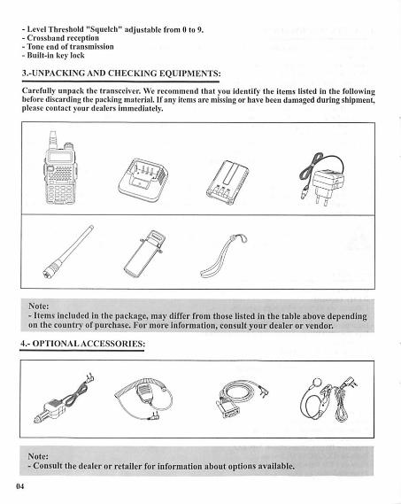
3.-UNPACKINGAND CHECKING EQUIPMENTS:
Carefully unpack the transceiver. We recommend that you identify the items listed in the followingbefore discarding the packing material. If any items are missing or have been damaged during shipment,please contact your dealers immediately.
Note:
- Items included in the puckage, may differ from those listed in the table above dependingon the country of purchase. For more information, consult your dealer or vendor.
4.-OPTIONAL ACCESSORIES:
Note:iiore:
- Consult the dealer or retailer for information about options available.
04
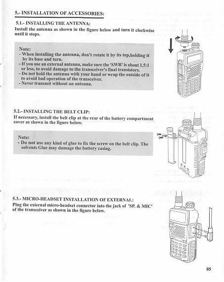
5.- INSTALLATION OF ACCESSORIES:
5.1.- INSTALLING THE ANTENNA:
Install the antenna as shown in the figure belowand turn it clockwiseuntil it stops.
Note:
- When installing the antenna,don't rotate it by its top.holding itby its base and turn.
- If you use an external antenna, make sure the 'SWR' is about 1.5:1or less, to avoid damage to the transceiver's final transistors.
- Donot holdthe antenna with your hand or wrap the outsideof itto avoid bad operation of the transceiver.
- Never transmit without an antenna.
5.2.- INSTALLING THE BELT CLIP:
If necessary, install thebelt clipat therearofthebatten compartmentcover as shown in the figure below.
Note:
- Donot use any kind ofglue to fix thescrew onthebelt clip. Thesolvents Gluemaydamage the battery casing.
5.3.- MICRO-HEADSET INSTALLATION OF EXTERNAL:Plug theexternal micro-headset connector intothejackof 'SP. & MICof the transceiveras shown in the figure below.
05
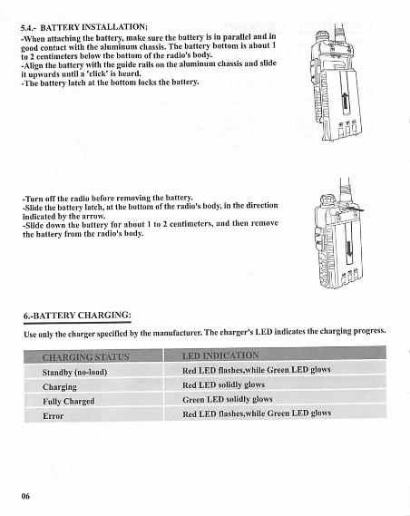
5.4.- BATTERY INSTALLATION:
-Whenattachingthe battery, makesure the battery is in parallel and ingood contact with the aluminum chassis. The battery bottom isabout 1to 2 centimeters below the bottom of the radio's body.-Align thebattery with theguide rails onthealuminum chassis andslideit upwards until a 'click' is heard.-The battery latch at the bottom locks the battery.
-Turn off the radio before removing the battery.-Slidethe batten latch, at the bottomof the radio's body,in the directionindicated bv the arrow.-Slide down the battery for about 1 to 2 centimeters, and then removethe battery from the radio's body.
6.-BATTERY CHARGING:
Use only the charger specified by the manufacturer. The charger's LED indicates the charging progress.
CHARGING STAT
Standby (no-load)
Charging
Fully Charged
Error
06
LEI) INDICATION
Red LED flashes,while Green LED glows
Red LED solidly glows
Green LED solidly glows
Red LED flashes,while Green LED glows

Please follow these steps:1. Plug the power cord into the adapter.2. Plug the AC connector of the adapter into the AC outlet socket.3. Plug the DC connector of the adapter into the DC socketon the back of the charger.4. Place the radio with the battery attached, or the battery alone, in the charger.5. Make sure the batten is in good contact withthe chargingterminals. The chargingprocess initiates
when the red LED lights.6. The green LED lights about 4 hours later indicating the battery is fully charged. Then remove theradio with the battery attached or the batten, alone from the charger.
7. -BATTERY INFORMATION:
7.1.-INITIALUSE
Newbatteries arc shipped uncharged fully from the factory.Charge a new battery for 5 hours beforeinitial use.The maximum batten capacityand performance isachieved after threefull charge/dischargecycles. If you notice the batten power runs low,please recharge the battery.
A WARNING:-To reduce the risk of injury, charge only the battery specifiedby themanufacturer. Otherbatteriesmayburst,causing bodily injuryand propertydamage.-To avoid risk of personal injury, do not dispose of batteries in a fire!
-Dispose of batteriesaccording to localregulations (e.g. recycling). Do notdispose as householdwaste.
-Never attempt to disassemble the battery.
7.2.-BATTERY TIPS:
1. When charging your battery, keep it at a temperature among5t - 40'C. Temperature out of thelimit may cause battery leakage or damage.2. When charging a batten attached to a radio, turn the radio off to ensure a full charge.3. Do not cut off the power supply or remove the battery whencharging a battery.4. Never charge a battery that is wet. Please dry it with a soft cloth prior to charge.5. The battery will eventually wear out. When the operating time (talk-time and standby time) isnoticeably shorter than normal performance, it is time to buy a new battery.
7.3.-PROLONG BATTERY LIFE:
1. Battery performance will be greatly decreased at a temperature below Ot. Aspare battery isnecessary in cold weather. The cold battery unable to work in this situation may work under roomtemperature, so keep it for later use.
07

2.The dust on the battery contact may causethe battery cannot work or charge. Please use a cleandry cloth to wipe it before attaching the battery to the radio.
7.4.-BATTERY STORAGE:
1. Fullycharge a battery before you store it for a long time, to avoid battery damage due to over-discharge.2. Recharge a battery after several months' storage (Li-Ion batteries: 6 months), to avoid batterycapacity reduction due to over-discharge.3. Store your battery in a cooland dry placeunder roomtemperature, to reduceself-discharge.
8.-PARTS. CONTROLS AND KEYS:
8.1.-RADIO OVERVIEW:
1. antenna 10. strap buckle
2. flashlight 11.accessory jack
3. knob (ON/OFF,volume) 12.A/B key(frequency display switches)
4. LCD 13.BAND key(band switches)
5. SK-side keyl/CALL(radio,alarm) 14.keypad
6. SK-side key2/MONI(flashlight,monitor) 15.SP.&MIC.
7. PTT kcy(push-to-talk) 16.battery pack
8. VFO/MR (frequency mode/channel mode)
9. LED indicator
17.battcry contacts
18.battery remove button
08

8J.- COMMAND/KEY DEFINTTION:
• [PTTl(PUSH-TO-TALK):Press and hold down the [PTT] button to transmit; release it to receive.
• SK-SIDE KEY1/|CALL):- Press the [CALL] button.to activate the FM Radio;Press it again to deactivate the FM Radio.- Press and bold on the [CALL|button,to activate the alarm function; Press and hold it again,todeactivate the alarm function.
• SK-SIDE KEY2/[MONI):-Press the [MONIJ button,to turn on the flashIight;Press it again to turn off.Press and hold on the[MONI] button,to monitor the signal.
•IVFO/MRIBUTTON:-Press the [VFO/MR] button,™ switch the frequency mode and channel mode,
•IA/B]BUTTON:-Press the [A/B] button.to switch frequency display.
•[BAND1BUTTON:-Press the [BAND]button,to switch band dispaly.-While FM radio being activated.press the [BANDJbutton to switch the band of FM radiofband 65-75MHz/76-108MHz).
•t*SCAN]KEY:•Press the (*SCAN) key to activate the Reverse function,it will exchangea separate reception andtransmission frequency.-Press the [*SCAN] key for 2 seconds to start scanning(frequency/channel).- While FM radio being activated.press the hvSCAN] key to search FM radio station.-While setting the RX CTCSS/DCS, press the key [*SCAN] to scan the RX CTCSS/DCS.
•l#n-»] KEY:-Under channel mode, press [#n-»] key to switch High/Low transmit power.-Press I#p-»] key for 2 seconds to lock/unlock the keypad.
•FUNCTION KEYPAD:-|MENU]key:-To enter the menu of the radio and confirm the setting.-WWkey:-Press and hold |A]or(*]key for frequency up or down fast.-Press [A]or(A]key,the scanning will be opposite.-[EXITlkey:•To cancel /clear or exit.
•NUMERIC KEYPAD:-Used to enter information for programming the radio's lists and thenon-standard CTCSS
-Under transmission mode, press the numeric key to send the signalcode(tbe code should be set by PC software).
09
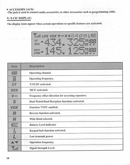
• ACCESSORY JACK:-The jackisused toconnect audio accessories, or other accessories such asprogramming cable.
9.-'LCD' DISPLAY:
Thedisplay icons appearwhen certain operations or specific features are activated.
Tilll LDS VOX+- RNa 0 £> h st^CT ADCS
m
• •
• •••••• y jB
••••• ••
• •
::... 75'QO|',tou
.'...'25 a *m
• ••••• • •• •••••
5T2T
DTMF^"3
1• ••• ••
IvLiOO.-..."25*- *
Icon Description
>00 Operating channel.
7525
Operating frequency.
CT 'CTCSS' activated.
DCS 'DCS' activated.
+ - Frequency offset direction for accessing repeaters.
s Dual Watch/Dual Reception functions activated.
vox Function 'VOX' enabled.
R Reverse function activated.
N Wide Band selected.
tfjTT Battery Level indicator
$ Keypad lock function activated.
L Low transmit power.
•*."•" Operation frequency.
Xm Signal Strength Level.
Ill

10.- 1750 HZTONE FOR ACCESS TO REPEATERS:
The user needs toestablish long distance communications through an amateur radio repeater whichisactivated afterreceiving a 1750 Hz tone. Press andhold onthe|PTT|,thcn press the[BAND] buttonto transmit a 1750Hz tone.
11.-BASIC OPERATION:
ll.l.-RADIO ON-OFF/VOLUME CONTROL:-Makesure the antenna and batten are installed correctlyand the battery charged.-Rotate the knob clockwise to turn the radio on, and rotate the knob fully counter-clockwise until a'click' is heard to turn the radio off. Turn the knob clockwise to increase the volume,or counterclockwise to decrease the volume.
11.2.-SELECTING A FREQUENCY OR CHANNEL:-Press the keylA]or|A|to select the desired frequency/channel you want. The display shows thefrequencv / channel selected.-Press and hold down the key |A]or|A| for frequency up or down fast.
Note:- You can not select a channel if not previously stored.
12-ADVANCED OPERATION:
You can program your transceiver operating inthe setup menu tosuit your needs orpreferences.
12.1.-SET MENU DESCRIPTION:
Menu Function/Description Available settings
0 SQL (Squelch level) 0-9
1 STKP(Frequency step) 2.5/5/6.25/10/12.5/25kHz
2 TXPfTransmit power) HIGH/LOW
3 SAVE( Batten save.l: 1/1:2/1:3/1:4) OFF/1/2/3/4
4 VOX(Voiceoperated transmission) OFF/0-10
5 W/N( Wideband/narrowband) WIDE/NARR
6 ABR(Display illumination) OFF/1 /2/3/4/5s
7 TDR(Dual watch/dual reception) OFF/ON

8 BEEP(Keypad beep) OFF/ON
9 TOTfTransmission timer) 15/30/45/60„7585/600seconds
10 R-DCS(Reception digital coded squelch) OFF/D023N...D754I
11 R-CTS(Recepfion Continuous Tone Coded Squelch) 67.0Hz...254.1Hz
12 T-DCS(Transmission digital coded squelch) OFF/D023N...D754I
13 T-CTS(Transmission Continuous Tone Coded Squelch) 67.0Hz...254.1Hz
14 VOICE(Voice prompt) OFF/ON
15ANKAutomatic number identificationof the radio,onlycan be set by PC software.
16 DTMFSTfThe DTMF tone of transmitting code.) OFF/DT-ST/ANI-ST/DT+ANI
17 S-CODE(Signal code,onlycouldbe setby PCsoftware.) 1,...,15 groups
18 SC-REV(Scan resume method) TO/CO/SE
19PTT-ID(press or release the PTT button to transmit thesignal code) OFF/BOT/EOT/BOTH
20 PTT-LT(de!aythe signal code sending) 0,.^30ms
21MDF-A(underchannel mode, A channeldisplays.Note:name display only can be set by PC software. FREQ/CH/NAME
22MDF-B(under channel mode, B channel displays. Note:name display only can be set by PC software. FREQ/CH/NAME
23 BCL(busy channel lockout) OFF/ON
24 AUTOLK(keypad locked automatically) OFF/ON
25 SFT-D(direction of frequency shift) OFF/+/-
26 OFFSET(frequency shift) 00.000...69.990
27 MEMCH(stored in memory channels) 000, ...127
28 DELCH(delete the memory channels) 000, ...127
29 WT-LED(illuminationdisplay colorof standby) OFF/BLUE/ORANGE/PURPLE
30 RX-LED(lllumination display colorof reception) OFF/BLUE/ORANGE/PURPLE
31 TX-LED(ilIumination display colorof transmitting) OFF/BLUE/ORANGE/PURPLE
32 AL-MOD(alarm mode) SITE/TONE/CODE
33 BAND(band selection) VHF/UHF
34TX-AB(transmitting selection while in dual watch/reception) OFF/A/B
35 STEfTall Tone Elimination) OFF/ON
12

36
37
38
39
40
RP_STE(Tail toneelimination in communication throughrepeater)
RPT_RL(Delay the tail tone of repeater)
PONMGS(Boot display)
ROGER(tone end of transmission)
RESET (Restore to default setting)
OFF/1,2,3...10
OFF/1,2,3...10
FULL/MGS
ON/OFF
VFO/ALL
12.2.-SHORTCUT MENU OPERATION:
l.-PrcssthekeyMENU,then pressthekeyA or• to select thedesired menu.2.-Pressthe keyMENU again,cometo the parameter setting.3.-Press the kcv A or • to select the desired parameter.4.-Press thekey MENU toconfirm andsave, press thekey EXIT tocancel setting or clear theinput.
MENU N0-PARAMETER
1
MENU NO-• PARAMETER
MENU• PARAMETER
enNO. MENU ™
PARAMETER
-Note:Under channel modc.the following menu settings are invalid:CTCSS,DCS,W/N,PTT-ID,BCL,SCAN ADD TO,S-CODE,CHANNEL NAME.Only the H/L power could bechanged.
12.3.-"SQL" (SQUELCH):-The squelch mute the speaker of the transceiver in the absence of reception. With the squelch levelcorrectly set, you will hear sound only while actually receiving signals and significantly reduces batterycurrent consumption. It is recommended that you set Level 5.
12.4.- FUNCTION "VOX" (VOICE OPERATEDTRANSMISSION):-This function is not necessary topush the |PTT1 on the transceiver for a transmission. Transmissionis activated automatically by detecting the radio voice. When finish speaking, the transmissionautomatically terminated and the transceiver will automatically receive signal. Be sure to adjust theVOX Gain level to anappropriate sensitivity toallow smooth transmission.
12.5.- SELECT WIDEBAND OR NARROW BAND "W/N":Inareas where the RF signals aresaturated, you must use the narrow band oftransmission to avoidinterference in adjacent channels.
12.6.-TDR (DUALWATCH/DUAL RECEPTION):This feature allows you tooperate between frequency Aand frequency B. Periodically, thetransceiverchecks whether a signal is received onanother frequency thatwe have scheduled. Ifyou receive asignal, the unit willremain in the frequencyuntil the received signaldisappears.
13

12.7.-TOT(TRANSMISSION TIMER):
This function can automatically control the time we transmit each time you press [PTT] on thetransceiver. This feature isvery useful toavoid overheating excessive power transistors ofthetransceiver.Ihetransceiver will beofftransmission automatically once thesettime.
12.8.-CTCSS/DCS:
Insome cases only want toestablish communications inaclosed user group ata particular frequencyor channel, for it will use "CTCSS" or code "DCS"for reception.The "squelch" opens only when receiving a frequency with "CTCSS" or codes "DCS" same as theprogrammed in yourtransceiver. If codes of the received signal differs from those programmed inyour transceiver, the "squelch" will not openand the received signalcan be heard.
Note:
- The use of "CTCSS" or "DCS" in a communication, does not guarantee completeconfidentiality communication.
12.9.-ANI
-ANI (Automatic Number Identification) is also known as PTT ID because an ID is transmitted whenthePI r button oftheradio ispressed and/or released. This IDtells thedispatcher which field radiowas keyed.Only could be set by PC software.
12.10.- DTMFST(DTMFTONEOF TRANSMITTING CODE):First you should set the PIT-ID as BOT/EOT/BOTH-"OFF"-Under transmitting mode, you can'theartheDTMF tone, while you press thekey totransmitthe code or code automatically transmitted.-"DT-ST"-Under transmitting mode, you can hear the DTMF tone, while you press thekey totransmitthe code.
-"ANI-ST"-under transmitting mode, you can hear the DTMF tone, while the code automaticallytransmitted.
-"DT-ANI"-under transmitting mode, you can heartheDTMF tone, while you press thekey totransmitthe code or the code automatically transmitted.
12.11.-SC-REV(SCAN RESUME METHOD):
Thistransceiver allows youtoscanmemory channels, all the bandsor part orthe bands.When the transceiver detects a communication, thescan will stop automatically.
Notes:- "TO" (Time Operation):Scanning will stop when it detects anactive signal. Thescanning will stop on each channel oractivefrequency for a predeterminedtime,after that time the scan willresumeautomatically.- "CO (Carrier Operation):
^•^f^"1"8,"^1 S,op and mnain in ,hefrequency orchannel, until the active signal disappears.- "SE"(Search Operation):
The scanning will stop and remain in the frequency orchannel after itdetects anactive signal.
12.12.- PTT-ID(PTT OR RELEASE PTT TO TRANSMIT THE SIGNAL CODE):-This feature allows you to know who call you.-"OFF"-Don't transmit thecode while push thePTT button. „„«™™™> \-"BOT"-Transmit the code while push the PTT button.(the code only could be set by PC software.)-"EOT"-Transmit the code while release the PTT button.-"BOTH"-Transmit the code while pushor release the PTTbutton.
12.13.- BCL(BUSY CHANNEL LOCKOUT):The BCLO feature prevents the radio's transmitter from being activated if asignal strong enough tobreak through the "noise" squelch is present. On afrequency where stations us.ng different CI CSSorDCS codes may be active, BCLO prevents you from disrupting their communications accidental!)(because your radio may be muted by its own tone decoder).
12.14.- SFT-D(DIRECTION OFFREQUENCY SHIFT):The "OFFSET" is the difference or offset between the reception frequency and the frcquency oftransmission for access to amateur radio repeaters. Set the "OFFSET" according to the OFFSETamateur radio repeater through which want to communicate.
12.15.- OFFSET(FREQUENCY SHIFT):When communicating via a repeater, the direction of displacement of frequency should be timed tothe displacement ofthe transmission frequency is higher orlower than the receiving frequency.
If we want to make acommunication through amateur radio repeater whose frequency Input fa MSfi00MHz and 145,600 MHz is output, we select the "OFFSET" of^.T^^n^Tfi^ue^direction oftravel "SHIFT" programmed to [-], so the transceiver will always 145,600 MHz in frequencyand when you press [PTT! to transmit transceiver, the frequency will automatically move to145,000 MHz
12.16.-STE (TAIL TONE ELIMATION):This function is used to activate or deactivate the transmission end of the transceiver, ^^altonetransmission only be used in communications between transceivers and not in communications tlirougna repeater,whichmust be deactivated.
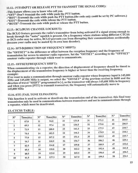
13.-CTCSS TABLE:
N°
l
Tone(IIz)
67.0
N°
11
Tone(llz)
94.8
N°
21
Tonc(Hz)
131.8
N°
31
Tone(Hz)
171.3
N°
41
Toned I/)
203.?
2 69.3 12 97.4 22 136.5 32 173.8 42 206.5
3 71.9 13 100.0 23 141.3 33 177.3 43 210.7
4 7-1.4 14 103.5 24 146.2 34 179.9 44 218.1
5 77.0 15 107.2 25 151.4 35 183.5 45 225.7
r. 79.7 16 110.9 26 156.7 36 186.2 46 229.1
7 82.5 17 114.8 27 159.8 37 189.9 47 233.6
8 85.4 18 118.8 28 162.2 38 192.8 48 241.8
9 88.5 19 123.0 29 165.5 39 196.6 49 250.3
10 91.5 20 127.3 30 167.9 40 199.5 50 254.1
15
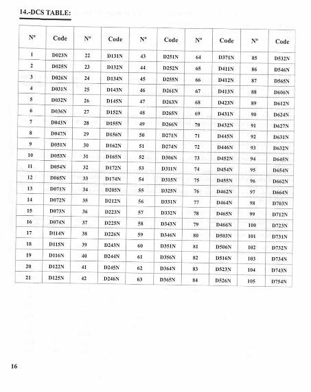
14.-DCS TABLE:
N° Code N° Code N° Code N° Code N° Code
1 D023.N 22 D131.N 43 D251N 64 D371N 85 D532N
2 D025.N 23 D132N 44 D252N 65 D411N 86 D546N
3 D026.N 24 D134N 45 D255N 66 D412N S7 D565N
4 D03IN 25 D143N 46 D261N 67 D413N 88 D606N
5 D032N 26 D145.N 47 D263N 68 D423.N 89 D612N
6 D036N 27 D152N 48 D265N 69 1)43 IN 90 D624N
7 D043N 28 D155N 49 D266N 70 D432N 91 D627N
8 D047N 29 D156N 50 D27I.N 71 D445.N 92 R631.N
9 DOSIN 30 D162N 51 D274N 72 D446N 93 D632N
10 D053N 31 DI65N 52 D306N 73 D452N 94 D645N
11 D054.N 32 D172N 53 D311N 74 D454N 95 D654N
12 D065N 33 DI74N 54 D315N 75 D4S5N 96 D662N
13 D071N 34 D205N 55 D325N 76 D462N 97 D664N
14 D072X 35 D212N 56 D33I.N 77 D464N 98 D703.N
15 D073.N 36 D223N 57 D332N 78 D465N 99 D712N
16 D074N 37 D225N 58 D343N 79 D466N 100 D723N
17 D114N 38 D226.N 59 D346N 80 D503N 101 1)73 IN
18 D115N 39 D243N 60 D3S1N 81 D506N 102 D732N
19 D1I6N 40 D244N 61 D356N 82 D516N 103 D734.N
20 D122N 41 D245N 62 D364N 83 D523N 104 D743N
21 D125N 42 D246N ' 63 D365N 84 D526N 105 D754N
16

15.-TECHNICAL SPECIFICATION:
15.1.-GENERAL:
Frequency range
Memory channels
Frequency stability
Frequency step
Antenna impedance
Operating temperature
Supply voltage
Consumption in standby
Consumption in reception
Consumption in transmission
Mode of operation
Duty- cycle
Dimensions
Weight
15.2.-TRANSMITTER:
RF power
Type of modulation
Emission class
Maximum deviation
Spurious emissions
15.3.-RECEIVER:
Receiver sensitivity
Intcrmodulation
Audio output
Adjacent channel selectivity
Note:
65MHz-I08MIIz(Only commercial FM radio reception)VHF:136MHz-174MHz (Rx7Tx).UHF:400MHz-480MHz (RxATx)
Up to 128 channels
2.5ppm
2.5kHz/5kHz/6.25kHz/10kHz/12.5kHz/25kIIz
50 Q
-20 °C to +60 t
Rechargeable Lithium-Ion mAh 7.4V/1800
£75mA
380mA
=£1.4 A
Simplex or semi-duplex
03/03/54 min. (Rx / Tx / Standby)
58mm x 110mm x 32mm
130 g (approximate)
4W/1W
FM
16KCDF3E/11K© F3E (W/N)
« ±5 kHz/=S ± 2.5 kHz (W/N)
<-60 dB
0.2 u V(at 12dBSINAD)
60 dB
lOOOmW
65/60dB
-All specifications shown are subject to change without notice
17

^.-TROUBLESHOOTING:
Problem Possible cause / solution
The radio does not start.
The battery is low, replace the battery with a charged batteryor proceed to the battery.The battery is not installed correctly, remove the battery andreattach it.
The battery runs down quickly.The battery life has come to an end, replace the battery witha new one.
The batten is fully charged, make sure the batten is made in full.
The receiving indicator LEDlights but do not hear the speaker.
Make sure the volume setting is too low.Make sure the undertones "CTCSS" or code "DCS" are the
same as those programmed in the transceiver of the othermembers of your group.
When transmitting, the othermembers of his group do notreceive the communication.
Make sure the undertones "CTCSS" or code "DCS"
programmed in your transceiver are the same as thoseprogrammed in the transceiver of the other members of yourgroup.
Your partner or you, are too far.You or your partner are in a bad area of RF signal propagation.
In"standby"mode, the transceivertransmits without pressing the"PTT".
Check the level adjustment function "VOX" is not set too sensitive.
Receive communications from
other user groups whilecommunicating with your group.
Change frequency or channel.Change the undertones "CTCSS" or code "DCS" in your group.
Communication with other
members of your group is pooror low quality.
You or your partner is too far away or in an area of poor radio signalpropagation, such as inside a tunnel, inside an underground carpark, in a mountainous area, including large metal structures, etc..
Once these checks, if you still have problems with the transceiver, check with your distributor,dealer or service center.
18

17.-WARRANTY: (Better buy the radios from localdealer).
WARRANTY CERTIFICATE
Brand: Model no.: Serial no.:
Name of purchaser:
Address:
City: Zip code:
Seal and name of the dealer:
Province/State: Tel no.:
Date of purchase:
WARNING: Warranty is valid provided it is complete andproperly filled in legibly and clearly present the seal andname of the dealer and have attached the bill proof ofpurchase of equipment.
The devicedescribed in thisCertificate is guaranteed fora period of oneyear from the dateof saleto thefinaluser.This Warranty Certificateis unique and not transferable and may not be reissued fornew ororiginal or copy. Substitution of product failure or any part thereofshall not involve extension of theguarantee.Thewarranty covers thereplacement andfree replacement ofallparts thatare defective inmaterials andcomponents used in manufacturing and / or assembly of the apparatus.The warranty does notcover any faults caused byaccident, improper installation anduse, electric shock(egstorms),connect a power other than that specified, reverse polarity in the diet,or claims due todeterioration in theexternal appearance ofnormal use,northeamount orcondition oftheaccessories.Checkingthe accessories isthe responsibility of the purchaser at the time of purchasing the device.Thewarranty does notcover rechargeable batteries even if theyare partof theequipment purchased astheyareconsidered consumables, the impairment mustbe reported withina period of fifteen days fromthe date of purchase.The warranty fa void on the followingassumptions:1.- Devices that havebeenmanipulated by anotheror by anyoneotherthan authorized service provider.2.- Equipment andaccessories inwhich theserial numberhasbeen altered, deleted or filed unreadable.3. - Useof the product than as intended.To makeuseof theguarantee fa necessary to give thedealer oranyof theAuthorised Service thedefectivedevice with its accessories and the following documentation:1.- WarrantyCertificate dulycompleted andsealed.2. - Original invoicewhich clearlyidentifies the deviceand the date of purchase.3. - Description of the faults.The warranty termscontained inthisCertificate ofGuarantee donotexclude, modifyorrestrict thestatutoryrights of thebuyerbyvirtueof thelawsin force at thetimeof purchase, but areadded to them.
19
