transceiver design and power allocation for swipt in mimo
TRANSCRIPT

symmetryS S
Article
Transceiver Design and Power Allocation for SWIPTin MIMO Cognitive Radio Systems
Fahui Wu 1, Lin Xiao 2,*, Dingcheng Yang 2, Laurie Cuthbert 3 and Xiaoping Liu 1,4
1 Jiangxi Province Key Laboratory of Intelligent Information Systems, Nanchang University,Nanchang 330031, China; [email protected] (F.W.); [email protected] (X.L.)
2 Information Engineering School, Nanchang University, Nanchang 330031, China;[email protected]
3 Information Systems Research Centre, Macao Polytechnic Institute, Macao 999078, China;[email protected]
4 Department of Systems and Computer Engineering, Carleton University, Ottawa, ON K1S 5B6, Canada* Correspondence: [email protected]
Received: 17 October 2018; Accepted: 12 November 2018; Published: 18 November 2018 �����������������
Abstract: In this paper, we consider a symmetric wireless communication network, i.e., each useris equipped with the same number of antennas. Specifically, this paper studies simultaneouswireless information and power transfer (SWIPT) in a K-user multiple-input multiple-output (MIMO)cognitive radio network where the secondary users (SUs) access the same frequency band as thepre-existing primary user (PU) without generating any interference. The transceivers and powersplitting ratio are designed and power allocation is considered in our system model. To guarantee thesignal-to-interference-plus-noise ratio (SINR) and harvested energy requirement of the PU, its optimaltransceiver and minimal transmitted power are obtained by the technique of semi-definite relaxation(SDR). We design the beamformers of the SUs using the distance between the interference subspacesat the PU and the null space of PU’s desired signal to preserve the PU from the interference causedby the SUs. We aim to maximize the sum rate of all the SUs by jointly designing power splittingratios and allocating transmission power. Furthermore, to consider the performance fairness of SUs,we propose another approach to maximize the minimum SINR of the SUs. Finally, numerical resultsare given to evaluate the performance of proposed approaches.
Keywords: simultaneous wireless information and power transfer (SWIPT); power splitting;cognitive radio; multiple-input multiple-output (MIMO)
1. Introduction
Wireless power transfer (WPT) techniques have generated interest from both academia andindustry over the past decades [1–7]. Generally speaking, WPT can be achieved via mainlythree methods, i.e., inductive coupling [1,2], magnetic resonant coupling [3,4] for near-field WPT,and electromagnetic (EM) radiation [5,6] is a far-field WPT technology, also known as radiative WPT.In radiative WPT, users convert the received radio frequency (RF) signal into electricity. Comparedto the two near-field WPT techniques, radiative WPT can implement power transfer over distancesvarying from a few meters to several kilometers. As a result, radiative WPT is considered as asuitable solution to support next-generation wireless communication networks without the need tocharge batteries via electrical wire. This is crucial for those devices which cannot be charged viawire, such as sensors embedded in body or building. Since RF signals can carry energy as wellas information, combining RF wireless power transfer and information transmission leads to thesimultaneous wireless information and power transfer (SWIPT) [6]. This concept was proposed firstly
Symmetry 2018, 10, 647; doi:10.3390/sym10110647 www.mdpi.com/journal/symmetry

Symmetry 2018, 10, 647 2 of 19
in [8], where the authors characterized the rate-energy regions for point-to-point SWPIT systemswith noisy channels. In [6], a three-user multiple-input multiple-output (MIMO) broadcast systemsfor SWIPT was investigated, with two practical receiver structures to enable SWIPT being proposed:(i) “time switching” (TS) with the receiver switching its operations periodically between energyharvesting (EH) and information decoding (ID); and (ii) “power splitting” (PS) with the receiversplitting the received signal into two streams, one for EH and another for ID. With the practical SWIPTschemes introduced above, the applications of SWIPT have been investigated in various networkconfigurations, such as point-to-point single-antenna channel [9], orthogonal frequency divisionmultiplexing (OFDM)-based multiple users system [10], and relay channel [11].
1.1. Related Works
One of the key challenges in most wireless communication systems is interference, and there isno exception in multi-user SWIPT systems. In this paper, we pay attention to performing SWIPT ina cognitive interference channel (IFC), in which there is one primary transmitter–receiver pair andseveral secondary user pairs. According to the methods applied for interference management, priorresearch on SWIPT in IFC network can be loosely classified into two categories. In the first category,the beamforming matrix and the PS ratio are jointly optimized [12–15]. In [12], a multiple-inputsingle-output (MISO) systems with perfect channel statement information (CSI) is investigated forSWIPT, and a centralized algorithm is proposed to solve joint beamforming and power splitting(JBPS) problem. Then, this work is extended to imperfect CSI at the transmitters in [13], the proposeddecentralized algorithm being guaranteed to coverage to the centralized solution. In a more complexK-pair MIMO interference channel [14], three transceiver designs with different computationalcomplexity are proposed to solve the JBPS problem. However, an oversimple, identical PS ratioover all the receiver antennas is assumed in [14]. To achieve a more optimal PS scheme, with afull-duplex K-pair MIMO interference channel scenario [15], the authors took into account a PS vector(i.e., different ratios for different receive antennas). The main objective of those works is to minimize thetotal transmit power, while satisfying the signal-to-interference-plus-noise ratio (SINR) and harvestedenergy constraints (i.e., IT and EH requirements guaranteed). Due to the nonconvexity of the studiedJBPS problem, the intended problem can usually be relaxed as a tractable (centralized) semidefiniteprogram or second-order cone program, thus the developed solutions have lower computationalcomplexity but suboptimal performance.
Another category considers the interference alignment (IA) to manage the interference inEH IFC [16–19]. In IA-based networks, each user’s precoder can be cooperatively designed suchthat the interference at all the receivers only occupies a small subspace, so the intended information canbe reconstructed without interference through the decoder [16]. When applying IA to SWIPT networks,we can assume the signal stream fed into the ID receiver to be free of interference, thus bringing greatconvenience [17]. In [17], the authors first studied the joint transmit power allocation and powersplitting for IA, and IA was implemented via antenna selection in [18]. Moreover, the security issuein IA based SWIPT was also investigated in [19]. As a matter of fact, there is less research on the IAbased SWIPT.
On the other hand, since cognitive radio (CR) has been considered as a promising techniqueto solve the spectrum scarcity problem, many spectrum sensing schemes are developed for CRnetworks [20–23]; the CR SWIPT in CR networks also has attracted much attention [24–29]. The outageperformance of SWIPT is studied in [24] for a cognitive relay network. For MISO cognitive radiosystems, authors in [25] investigated the physical-layer secrecy problem, to protect the secrecy rateand energy harvesting of the primary user (PU), with a robust artificial noise aided beamformingand power splitting design being proposed under imperfect CSI. In the same system, authors in [26]jointly optimized beamforming and found power splitting ratios for the Max-Min problem by usingsemidefinite relaxation (SDR). In an underlay model MIMO CR network [27], a robust transceiver isdesigned for SWIPT, wherein the authors modeled the channel uncertainties by the worst-case model;

Symmetry 2018, 10, 647 3 of 19
they maximized the sum of harvested power at all the EH receivers under the minimum informationrate constraints at the secondary user (SU) and interference constraint at the PU. The physical layersecrecy problem is studied in a CR MIMO network in [28]; the authors investigated the artificial noise(AN)-aided precoding design problem and formulated the problem as a secrecy rate maximizationproblem, this problem being solved by a successive convex approximation method. Furthermore,the outage-constrained secrecy rate maximization problem is analyzed in [29], the transmit covariancematrix and artificial noise covariance matrix being optimized to maximize the secrecy rate.
1.2. Motivation and Contributions
In a CR network, specifically, an underlay spectrum sharing CR network, the power of interferenceand noise at the primary receiver is constrained by the interference temperature limit (ITL), so thatit is important to carefully control transmit power and to design the transmission precoder for SUsto successfully share spectrum. However, the interference from SUs can be salvaged as energy ifthe PU receiver is a SWIPT user. From the point of view of a SWIPT PU, maximizing the harvestedRF energy and minimizing the interference level are contradictory. Fortunately, the precoder designscheme of interference alignment IA can eliminate interference perfectly. When IA is applied to SWIPT,the interference-free signal steams are fed to the ID receiver, and the interference is fed to the EHreceiver for energy harvesting. Hence, in this paper, the interference from SUs to the PU is aligned intoa subspace in the PU. After that, to further improve the performance of the system, we consider thepower allocation (PA) among all users. To the best of our knowledge, there is no other existing workaccounting for the JBPS and power allocation of SWIPT in MIMO CR networks. The distinct featuresof our paper are as follows:
• The transceiver design and power allocation problem in a MIMO CR network is studied, and aninterference-alignment-based precoder design scheme for the SUs is proposed to protect thepriority of the PU. This problem is solved by alternating optimization and convex optimization.The minimum transmit power, optimal transceiver and power splitting ratio of the PU are derivedto guarantee its SINR and harvested energy constraints by using the SDR technique.
• The precoder of the SUs is analyzed by the theory of minimum squared Euclidean distance.The precoder of the SUs is obtained by eigenvalue decomposition of the interferencecovariance matrix.
• We propose a PA algorithm to maximize the sum rate of SUs. As the sum rate maximizationpower allocation algorithm may compromise some user’s performance, we further propose a PAalgorithm to maximize the minimum SINR of the SUs.
• The approaches proposed can be implemented in the CR network especially the unlicensedspectrum CR where a PU’s interest must be protected. Moreover, our solutions can be extendedto traditional communication network without WPT.
1.3. Organization and Notation
The rest of this paper is organized as follows. Section 2 presents the system model and problemformulation. The sum rate maximization solution and Max-Min solution are presented in Section 3.Section 4 presents numerical simulation results and analysis to validate our solutions. Section 5concludes the paper.
In this paper, we denote the scalars by lower-case letters, bold-face lower-case letter are usedfor vectors, A is a matrix, and A is a set. For a square matrix A, Rank(A), Tr(A), AT , and AH denoteits trace, rank, transpose and conjugate transpose, respectively. ‖·‖ denotes the Euclidean norm of avector, |·| denotes the absolute value a scalar, and A � 0 means A is a Hermitian positive semi-definitematrix. Im denotes an m by m identity matrix, and Cm×n denotes the space of m× n complex matrices.The distribution of a circularly symmetric complex Gaussian (CSCG) random vector with mean µ andcovariance matrix C is represented as CN (µ, C) .

Symmetry 2018, 10, 647 4 of 19
2. System Model and Problem Formulation
2.1. System Model
In this section, we present the system model and the formulation of our problem. As shownin Figure 1, consider a K-user interference CR network that consists of a single primary link andK − 1 secondary transmissions. The secondary users are allowed to share the licensed spectrumwith primary user as long as the interference temperature limit of the PU can be ensured. All thetransmitters simultaneously transfer information and energy to corresponding receivers, i.e., K-pairSWIPT users. Each transmitter and receiver is equipped with Mk and Nk antennas, respectively.The kth user transmits uncorrelated symbols xk which consist of dk ≤ min {Mk, Nk} data streams withtransmitting power Pk, i.e., E
[‖xk‖2] = Pk, xk ∼ CN (0, 1) .
SUs
PU
Receiver KTransmitter K
Receiver 2Transmitter 2
Transmitter 1 Receiver 1
KKH
11H
22H
1V
2V
KU
KV
2U
1U
Figure 1. System model.
To manage and eliminate interference and thus get a higher transmission degree of freedom (DoF),IA can be adopted on the network, which is called “IA-based CR network”. IA tries to jointly designthe precoder matrix for all transmitters so the that the desired signal can be extracted by a decodingmatrix. Let Vk of dimension Mk × dk and Uk of dimension Nk × dk, respectively, denote the precodingmatrix of the kth transmitter and decoding matrix of kth receiver. The received signal at the kth userwith perfect synchronization is:
yk = UHk HkkVkxk +
K
∑i=1.i 6=k
UHk HkiVixi + UH
k zk (1)
where Hki is the channel coefficient matrix from the ith transmitter to the kth receiver. zk representsthe additive white Gaussian noise vector (AWGN) at the kth receiver with distribution CN
(0, σ2INk
).
When IA is performed, the received interference at the kth receiver is constrained into the samesubspace that is orthogonal to the interference suppression matrix Uk. Thus, the desired signal canbe recovered from the remaining interference-free subspace. More specifically, when IA is feasible,the following conditions need to be satisfied:
UHk HkjVj = 0, ∀j 6= k
Rank(
UHk HkkVk
)= dk
(2)

Symmetry 2018, 10, 647 5 of 19
Similar to [30], this paper considers that all users have the same transceiver antennas and datastreams, i.e., Mk = M, Nk = N,anddk = d, thus the feasible condition for IA in this paper can bewritten as
d ≤ N2K + 1
+KM
2K + 1(3)
We assume that this condition holds throughout this paper.In this paper, we assume each receiver is equipped with a power splitter to process the received
signal. The received signal is split into two separate signal streams with different power levels, one sentto the ID receiver and the remaining fed to the EH receiver. Thus, the signal split to the the ID of kthreceiver with perfect interference elimination is expressed as:
yIDk =√
ρk
(UH
k HkkVkxk + zk
)+ nk (4)
where nk ∼ CN(0, δ2INk
)is the additional processing noise introduced when operate ID at receiver K.
Accordingly, the SINR of the kth user with perfect IA can be calculated as:
SINRk = Pkρk
ρkσ2 + δ2 UHk HkkVkVH
k HHkkUk (5)
On the other hand, the signal split to the EH of the kth receiver is given by:
yEHk =√
1− ρk
(K
∑i=1
HkiVixi + zk
)(6)
Then, the energy harvested by the EH of the kth user is given by
Ek = ζk(1− ρk)
(K
∑i=1
Pk‖HkiVi‖2 + σ2k
)(7)
where ζk(0 < ζk ≤ 1) is the energy conversion efficiency at the EH of kth receiver. When IA isleveraged in the SWIPT based CR network, not only can ID receive an interference-free signal, but itcan also re-utilize the interference as an energy source rather discard it. Therefore, IA can provide anefficient interference management solution for the SWIPT based CR network, in which the interferencebecomes a benefit and so does not need be discarded.
However, with IA, the SINR of the receiver may decrease in moderate or low SNR situations;this problem is something that should be avoided since the performance of the PU must not bedegraded, as that is a key objective of a CR network. To this end, we consider a situation wherethe PU neglects the presence of the SUs and retains their own transmission power and transmissionbeamforming. The SUs should design their preprocessing matrices and control their transmissionpower to guarantee the PU’s QoS, otherwise the SUs will not be allowed to access the licensed spectrum.Hence, the interference from SUs is aligned at PU, and the SINR of PU is expressed as
SINR1 = P1ρ1
ρ1σ21 + δ2
1UH
1 H11V1VH1 HH
11U1 (8)
Without loss of generality, to ensure the PU’s SINR metrics independent of the power oftransmit/receive filters, we assume ‖U1‖ = 1 and ‖V1‖ = 1 in the following. As an SU will alwayssuffer the interference from PU and other SUs, then the SINR of SUs is expressed as
SINRk =Pkρk|UH
k HkkVk|2
∑Kj 6=k ρk|UH
k HkjVj|2 + ρkσ2k ‖Uk‖2 + δ2
k‖Uk‖2(9)

Symmetry 2018, 10, 647 6 of 19
where k ∈ K, the set K = {2, 3, . . . , K}. Similarly, ‖Uk‖ = 1, k ∈ K is assumed. It should be noted that,in this paper, it is assumed that perfect knowledge of the channel is available at the PU, and the SUshave perfect knowledge of the all channel matrices (perfect CSI of the primary link is also availableat the SUs). The power allocation is considered for sum rate maximization among SUs, and theirpostprocessing matrices are designed to mitigate the received interference from the PU to improvetheir own performances. We consider the joint power allocation and pre/postprocessing matricesdesign for the CR-SWIPT network under these assumptions.
2.2. Problem Formulation
Considering that the only objective of the PU’s precoding matrix design is to satisfy the QoSrequirement on both SINR and harvested energy, interference from the PU to SUs may be ignored.The interference from the SUs to the PU is concentrated by the SU’s precoding matrices, and theneliminated by the PU’s decoding matrix. Moreover, a minimum harvested energy in the SUs should bemaintained to accommodate the receiver-side basic functions. Under these assumptions, we aim tomaximize the sum rate of all SUs. The joint power allocation and transceiver design problem can beformulated as:
max{Vk ,Uk ,ρk ,Pk}
K
∑k=2
SINRk,
s.t. P1ρ1
ρ1σ21 + δ2
1UH
1 H11V1VH1 HH
11U1 ≥ γ1,
ζk(1− ρk)
(K
∑j=1
Pj‖HjkVj‖2 + σ2k
)≥ ek, k ∈ K,
0 ≤ ρk ≤ 1, k ∈ K,
‖Vk‖2 = 1, k ∈ K,
UH1 H1kVk = 0, k ∈ K,
VHk Vk = I, UH
k Uk = I, k ∈ K,
‖U1‖2 = 1, ‖Vk‖2 = 1,K
∑k=1
Pk = Ptotal.
(10)
It is assumed that γ1 > 0 and all receivers have non-zero harvested energy targets, i.e., ek > 0,∀k;thus, the received PS ratios at all receivers should satisfy 0 < ρk < 1, ∀k. We can observe thatthe problem is nonconvex because the variables {Vk},{Uk},{ρk}, and{Pk} are coupled together inSINR constraints and EH constraints. This problem is still nonconvex even if fixing values of ρkwith 0 < ρk < 1, ∀k. The problem in Equation (9) is nonconvex and finding its global optimum isNP-hard. In the following, we propose an alternating optimization based solution to iteratively solvethe problem.
3. Alternating Optimization
3.1. Transceiver Design and Power Allocation for PU
Note that the PU self-centered performs its energy and information transmission; when PA amongusers is considered, the SINR and energy harvesting constraints of the PU should be satisfied. We firstderive the minimum transmitted power P∗1 , optimal transceiver, i.e., V∗1 , U∗1 , and optimal powersplitting ratio ρ∗1 of the PU that can guarantee its transmission threshold γ1 and e1. This problem canbe expressed as follows:

Symmetry 2018, 10, 647 7 of 19
minV1,U1,ρ1,{Pk}
P1
s.t. P1ρ1
ρ1σ21 + δ2
1UH
1 H11V1VH1 HH
11U1 ≥ γ1,
ζ1(1− ρ1)
(K
∑k=1
Pk‖H1kVk‖2 + σ21
)≥ e1,
0 ≤ ρ1 ≤ 1,
‖U1‖2 = 1, ‖V1‖2 = 1,K
∑k=1
Pk = Ptotal.
(11)
For Equation (10), we have two observations. First, the SINR of the PU is immune to the SUs’transmissions because of the IA; the PU’s decoder U1 is selfishly designed to improve its SINR.The closed form of optimal U∗1 that maximizes the SINR1 is [16]:
U∗1 = H11V∗1/‖H11V∗1‖ (12)
Second, the presence of SUs provides additional energy resource, i.e., interference to thePU’s EH receiver; note that VH
k Vk = I, k ∈ K, hence harvested energy at the PU turns into
Q1 = ζ1(1− ρ1)
(P1‖H11V1‖2 +
K∑
k=2Pk‖H1k‖2
). Let QSUs-PU =
K∑
k=2Pk‖H1k‖2 denote the harvested
energy portion that comes from SUs. If we fix the value of variables QSUs-PU and U1, and satisfy‖U1‖2 = 1 (the detail to choose QSUs-PU and U1 can be seen in the end of Section 3.2), theproblem becomes:
minV1,ρ1,P1
P1
s.t. P1ρ1
ρ1σ21 + δ2
1UH
1 H11V1VH1 HH
11U1 ≥ γ1,
ζ1(1− ρ1)(
P1‖H11V1‖2 + QSUs-PU
)≥ e1,
0 ≤ P1 ≤ Pmax, ‖V1‖2 = 1, 0 ≤ ρ1 ≤ 1.
(13)
The problem in Equation (12) is still nonconvex. Let X1 = P1V1VH1 , and then Rank(X1) ≤ 1.
By discarding the rank-one constraint, the SDR of problem with reformulating is given by
minX1,ρ1
Tr(X1)
s.t.1
γ1UH
1 H11X1HH11U1 ≥ σ2
1 +δ2
1ρ1
,(QSUs-PU + ‖H11X1HH
11‖2 + σ21
)≥ e1
ζ1(1− ρ1),
X1 � 0, 0 ≤ ρ1 ≤ 1.
(14)
Note that the SDR problem is convex, as both 1/ρ1 and 1/(1− ρ1) are convex functions overthe convex set 0 < ρ1 < 1, so it can be solved using some existing convex optimization solvers, e.g.,CVX [31]. Define X∗1 and ρ∗1 as the optimal solution to the problem; if X∗1 is indeed rank-one, thenthe optimal precoder can be obtained from the eigenvalue decomposition (EVD) of X∗1 expressed byX∗1 = x1λxH
1 , where λ denotes the only eigenvalue of X∗1 , hence the optimal precoder of PU is V∗1 = x1
and the optimal transmission power is P∗1 = λ as Tr(X∗1) = λ. Our only concern is whether the optimalsolution X∗1 satisfies the rank-one constraint, but, fortunately, it can be proved that the solution satisfiesRank(X1) = 1 by following proposition.

Symmetry 2018, 10, 647 8 of 19
Proposition 1. The optimal solution X∗1 and ρ∗1 of the problem with given γ1 > 0 and e1 > 0, leads to:
1. X∗1 satisfies Rank(X∗1) = 1.2. X∗1 and ρ∗1 satisfy SINR and EH constraint of the problem in Equation (14) with equality.
Proof of Proposition 1. This proposition can be proved by duality theory since the problem inEquation (14) is convex and satisfies Slater’s condition (discussed in more detail in Appendix A).The proposition indicates that the rank relaxation on X1 brings no loss of optimality to the problem,i.e., the SDR is tight.
3.2. Transceiver Design and Power Allocation for SUs
Next, we design the transceiver Vk,Uk, and optimize the power allocation Pk and the power splitterρk for the secondary links to maximize their sum rate; the optimization problem is formulated as:
max{Vk ,Uk ,ρk ,Pk}
K
∑k=2
SINRk,
s.t. ζk(1− ρk)
(K
∑j=1
Pj‖HjkVj‖2 + σ2k
)≥ ek,
K
∑k=2
Pk‖H1k‖2 ≥ QSUs-PU,
UH1 H1kVk = 0, VH
k Vk = I, ‖Uk‖2 = 1,
0 ≤ ρk ≤ 1,K
∑k=2
Pk = Ptotal − P∗1 ; k ∈ K.
(15)
It can be easily verified that the problem is nonconvex, thus the problem is difficult to be directlysolved. In the following, we consider a suboptimal algorithm to iteratively design transceiver Vk,Uk with fixed Pk and ρk, or optimize Pk, ρk with given Vk, Uk. The Vk, Uk with given ρk and Pk isoptimized as:
max{Vk ,Uk}
K
∑k=2
SINRk,
s.t. UH1 H1kVk = 0,
VHk Vk = I,
‖Uk‖2 = 1; k ∈ K.
(16)
The first constraints in Equation (16) indicate that SUs can transmit their signals without causingany interference to the PU. These constraints can be rewritten as follows:
−HkVk = 0,
−Hk
4= UH
1 H1k, k ∈ K. (17)
Equation (17) indicates that the subspace spanned by the matrix−Hk to be orthogonal the subspace
which spanned by the columns of the transmitter of each SU (Vk, k = 2, 3, . . . , K). Furthermore,to convert the IA problem with cognitive constraints into a standard IA problem, we have thefollowing definitions:
Vk4= Ak
∼Vk, k ∈ K. (18)
where Ak and∼Vk are of dimensions MK × (Mk − d1) and (Mk − d1)× dk, respectively; the columns of

Symmetry 2018, 10, 647 9 of 19
Vk should be a linear combination of the columns of Ak. The desired signal is projected onto U1 at thePU’s receiver, and interference signals from the secondary transmitters to PU’s receiver should lie inthe space spanned by the columns of {H1kVk}K
k=2. According to Equation (16), to avoid producinginterference on the PU, the received interference at the PU should lie in the null space of U1. To achievethis, we aim to minimize the distance between the null space of U1 and the space spanned by the PU’sreceived signal from the secondary links. To find the value of Ak, we have the following proposition:
Proposition 2. Given Bk as the orthonormal bases of space Ck, the N1×MK matrix H1k, k ∈ K and the matrixD such that D = H1kAk. The minimum squared Euclidean distance between the subspace spanned by thecolumns of D and the space Ck can be obtained by Ak whose columns are equal to the eigenvectors correspondingto the Mk − d1 minimum eigenvalues of HH
1kG1H1k, where G1 = IN1 − BkBHk .
Proof of Proposition 2. See [32], Lemma 1.
After finding the Ak, to improve the performance for secondary links by a giving closed-formsolution is equivalent to designing the transmitter to maximize the sum rate for a MIMO IFC: thisdoes not exist in general. As an alternative, we propose a solution minimizing the interferenceleakage to the PU. The reverse direction interference covariance matrix at the receivers is Qk =
PkH1kAkU1UH1 AH
k HH1k, k ∈ K, then the columns of
∼Vk are the dk least eigenvectors of reverse direction
interference covariance matrix Qk:∼Vk = vdk
min (Qk) (19)
Furthermore, the optimal V∗ that maximizes SINRk is obtained in a closed form as [16]:
U∗k = (Φk)−1 HkkVk/‖(Φk)
−1 HkkVk‖ (20)
where Φk = ∑Kj 6=k ρkHkjVjVH
j HHkj + ρkσ2IN + δ2IN . After finding the transceiver solution with given
ρk and Pk, we consider power allocation and power splitting ratio design with given Vk and Uk.
max{ρk ,Pk}
K
∑k=2
SINRk
s.t. ζk(1− ρk)
(K
∑j=1
Pj‖HkjVj‖2 + σ2k
)≥ ek,
K
∑k=2
Pk‖H1k‖2 ≥ QSUs-PU,
0 ≤ ρk ≤ 1,K
∑k=2
Pk = Ptotal − P∗1 ; k ∈ K.
(21)
It can be easily verified that the optimal ρ∗k satisfies the EH constraint of the problem inEquation (20) with equality. This conclusion can be proved by contradiction. Suppose the EHconstraint of problem holds with inequality, for any power allocation schemes, we can increase the ρk(i.e., decrease the 1− ρk) until the EH constraints to equal, the SINRk is increased as ρk becomes bigger.
Hence, the optimal ρ∗k for a given power allocation is ρ∗k = 1− ek/ζk
(K∑
j=1Pj‖HkjVj‖2 + σ2
k
). Given
the ρk, the power allocation power problem can be expressed as:

Symmetry 2018, 10, 647 10 of 19
max{Pk}
K
∑k=2
SINRk
s.t. ζk(1− ρk)
(K
∑j=1
Pj‖HkjVj‖2 + σ2k
)≥ ek,
K
∑k=2
Pk‖H1k‖2 ≥ QSUs-PU,
K
∑k=2
Pk = Ptotal − P∗1 ; k ∈ K.
(22)
This problem is nonconvex due to its objective function being nonconcave over Pk; by introducingvariables tk, we transform the the problem in Equation (21) into an equivalent convex problemas follows
max{Pk ,tk}
K
∑k=2
ρkPk|UHk HkkVk|2
s.t.K
∑j 6=k
ρkPj|UHk HkjVj|2 + tk
(ρkσ2
k ‖Uk‖2 + δ2k‖Uk‖2
)= 1,
ζk(1− ρk)
(K
∑j=1
Pj‖HkjVj‖2 + σ2k
)≥ tkek,
K
∑k=2
Pk‖H1k‖2 ≥ tkQSUs-PU,
tk > 0,K
∑k=2
Pk/tk = Ptotal − P∗1 ; k ∈ K.
(23)
It can be easily verified that, given any feasible solution {Pk, tk} to the problem in Equation (22),the solution {Pk/tk} to the problem in Equation (21) attains the same objective value as that of theproblem in Equation (22). Similarly, given any feasible solution {Pk} to the problem in Equation (21),it can be shown that with solution
{Pk/
(∑K
j 6=k ρkPj|UHk HkjVj|2 + ρkσ2
k ‖Uk‖2 + δ2k‖Uk‖2
)},
the problem achieves the same objective as that of the problem in Equation (21). Since the problem inEquation (22) is convex, this can be solved by CVX [31].
Our proposed sum rate maximization solution is summarized in Algorithm 1. Before executingAlgorithm 1, we need to first check the feasibility of Equation (9) and therefore find initial QSUs-PU
and U1 for the first iteration. We initialize the QSUs-PU = 0, and let the optimal receiver in transitionalpoint-to point MIMO channel as the initial value of U1. We update channel realization until theproblem in Equation (14) is solvable, and choose the corresponding QSUs-PU = 0 and U1 as the initialsolution for executing the Algorithm 1.

Symmetry 2018, 10, 647 11 of 19
Algorithm 1: Sum rate maximization algorithm.1: Initialize: give initial feasible QSUs-PU and U12: repeat
3: solve The problem in Equation (13) by CVX with U1;4: obtain V1 by EVD of X1;5: update U1 by (11);6: until converge or maximum number of iterations7: Output P∗1 = Tr(X1)8: calculate Vk by (17)9: obtain Uk by (19)
10: given a ρk;11: repeat
12: {Pk} ← solve the problem in Equation (22) by CVX with given ρk13: update ρk14: until converge or maximum number of iterations;15: Update QSUs-PU ;16: Repeat 2–15 until convergence or maximum number of iterations.
3.3. Maximize Minimum SINR Solution for SUs
Next, to avoid undesired SINR compromise by the sum rate maximization solution, we proposeanother solution to maximize the minimum SINR of SUs; the interference from the SUs to the PUneed be aligned into a same subspace, the SUs’ precoder should be the same as that in the Sum-Ratemaximization solution, hence we only focus on the power allocation and power splitting ratio designin this problem, which is formulated as:
max{ρk ,Pk}
mink
SINRk
s.t. ζk(1− ρk)
(K
∑j=1
Pj‖HkjVj‖2 + σ2k
)≥ ek,
0 ≤ ρk ≤ 1,
0 ≤ Pk ≤ Pmaxk ,
K
∑k=2
Pk = Ptotal − P∗1 ; k ∈ K.
(24)
It can easily be checked that problem is feasible if, and only if, ζk ∑Kj=2 Pmax
j ‖HjkVj‖2 ≥ ek,k = 2, . . . , K for given ek and Pmax
k . We assume that is always feasible; the problem is nonconvex sincethe transmit power Pk and the PS ratio ρk are coupled with each other in both the objective functionand the EH constraints. To make the problem tractable, we introduce a real-valued slack variable α
and then reformulate the problem as:
maxPk ,ρk ,α
α
s.t. α ≥ 0, α− SINRk ≤ 0,
ek − ζk(1− ρk)
(K
∑j=1
Pj‖HjkVj‖2 + σ2k
)≤ 0,
0 ≤ ρk ≤ 1,
0 ≤ Pk ≤ Pmaxk ,
K
∑k=2
Pk = Ptotal − P∗1 ; k ∈ K, .
(25)

Symmetry 2018, 10, 647 12 of 19
The problem in Equation (24) is convex for any given α, thus searching α over a specific andsolving the problem at each step with the associated α can obtain the optimal solution. Here, we givesome properties of the problem in Equation (24). If Pmax
k ≤ Ptotal − P∗1 for k ∈ K, then we have thefollowing propositions:
Proposition 3. If the SINR of link k is strictly less than that of all other links, i.e., SINR∗k < SINR∗j , ∀k 6= j,then P∗k = Pmax
k .
Proof of Proposition 3. Suppose this not true; we can increase transmit power within its maximumpower constraint, and decrease the j transmit power until both the SINR values are equal.This shows that the Max-Min SINR can always be increased until the Min-Min SINR reaches itsmaximum power.
Proposition 4. If the SINR of link k is strictly less than that of all other links, i.e., SINR∗k < SINR∗j , ∀k 6= j,the equality of the EH constraint holds at the receiver k, i.e., Qk = ek, while Qj ≥ ej at receiver j.
Proof of Proposition 4. Suppose that this is not true. That is, if SINRk < SINRj, the harvested powerat receiver k is Qk > ek. In this case, we can decrease ρk to increase SINRk until Qk = ek, which in turnincreases the Max-Min SINR value.
3.4. Solution Discussion
In this section, we discuss some importance issues to implement the proposed centralizedsolution. Generally speaking, all CSI should be globally available for centralized solutions [14],due to PU’s priority setting in our system model, only all SUs’ CSI should be known at the transceiverof all users to operate the algorithm. Thus, our proposed solution to reduce the CSI overhead ofPU is consistent with the principle of CR. Nevertheless, to implement the CSI exchange amongusers, a dedicated central processing unit should be deployed to collect CSI and then send that tocorresponding transmitters/receivers [14]. In fact, it is advisable to apply our proposed solution forslow fading channels.
Besides the CSI overhead, perfect CSI in transmitter and receiver are assumed. In practice,acquiring perfect CSI is a challenge due to many factors, such as channel estimation error, feedbackdelay, and the limited onboard energy. Note that the IA solution proposed in this paper has theassumption that the CSI is perfect; once the CSI changes, the solution of transceivers and powerallocation may no long match reality, thus imperfect CSI would lead to performance degradation. Tothat end, various robust transceiver designs have been studied for different networks (e.g., [13,25,27]).Hence, the imperfect CSI situation is beyond the consideration of this paper.
Another concern is the energy harvesting model issue. In this paper, we assume the energyconversion efficiency is a constant dependent of transmit power. The EH model being considered inthis paper is a liner model, which has the benefit of being analytically easily tractable. Indeed, theenergy conversion efficiency is not only a function of input signal shape and power, but also a functionof the transmit signal (beamforming, waveform, modulation, and power allocation) and the wirelesschannel state [33]. There has been an increasing interest in the SWIPT literature to study the nonlinearmodel, which describes the nonlinear characteristics of practical RF EH circuits [33–35]. Note thatin a nonlinear EH model, the CSCG inputs cannot achieve the Pareto optimal solution of the R-Eregion [34]. Studies on input distribution, modulation, and waveform designs are needed for nonlinearEH networks [35]. Moreover, research is in its infancy when it comes to multi-user SWIPT design forthe nonlinear models; to our knowledge, the R-E tradeoff of multi-user MIMO IFC remains largelyunknown. Thus, we consider a liner EH model in this paper, and the main idea applying IA to protecta PU’s priority and manage the interference can be extended to the nonlinear case. It important topoint out that the power allocation and beamforming radically changes once we change the energyharvester model and adopt more realistic nonlinear models of the energy harvester. The results present

Symmetry 2018, 10, 647 13 of 19
in this paper give a lower bound the for performance in practical nonlinear cases. It is of interest tore-think the power allocation and transceiver design for the nonlinear case in the future.
Finally, we discuss the computational complexity of Algorithm 1. CVX software [31] was appliedto solve the problem in Equation (14). The complexity of solving the problem in Equation (14) isO(√
M(M2 + M3)); the complexity of solving the problem in Equation (15) arises from the EVDoperation to compute the Vk and Uk, k ∈ K. Suppose the number of iteration to solve Equation (15) isTmax, the number of iterations to operate Algorithm 1 is Xmax, if M ≥ N, the complexity of Algorithm 1is O(Xmax
√M(M2 + M3) + XmaxTmaxKM3), else O(Xmax
√M(M2 + M3) + XmaxTmaxKN3).
4. Simulation Results
In this section, we provide some numerical simulation examples to validate the performance ofthe proposed approaches. We assume there is one PU with three SUs and all users have the sameset of parameters; each user is equipped with Mk = M, Nk = N antennas. The signal attenuationfrom transmitter to receiver is set as 40 dB for the direct channels and as 40 + 10log10ε dB for thecross-link channels [15], where ε is set as relative cross-link gain. Specifically, the variance of channelcoefficients is ωkk = 10−4 and ωkj = 10−4/ε for all k, j ∈ K, k 6= j. Moreover, ζ = 0.5, σ2 = −70 dBm,and δ2 = −50 dBm. The distance between transmitter and receiver is set as 3 m, and the frequencyof the carrier wave is assumed to be 900 MHz. The EH thresholds are set as being equal for all SUs,ek = e. We take the IA through all the users with the average power allocation (IA-APA) as benchmark.The total transmission power of the proposed solutions is set to be equal to that of full IA under thesame constraints.
First, we study the transmission power required at the PU versus the SINR target γ1 for theproposed solutions, with fixed parameters Mk = Nk = 4; all users’ EH threshold is −10 dBm.Total transmit power is set to be equal to that of IA-APA solution under the same conditions. Figure 2shows the performance comparison of the proposed solutions in terms of the minimum transmitpower, and it can be seen that the sum rate maximization solution has the best performance. It isobserved that, as the SINR γ1 is increased from 0 dB to 40 dB, more transmission power is needed,and the performance gap between the full IA solution and Max-Min solution gets closer, and Figure 2also shows that the performance of all solutions is not sensitive to the increasing SINR targets at low tomedium SINR; this is because the EH target is quite demanding.
0 5 10 15 20 25 30 35 40−25
−20
−15
−10
−5
0
5
10
γ1 [dB]
Avera
ge T
ransm
it P
ow
er
[dB
W]
IA−PAP solution
Max−Min Solution
Sum Rate Maximization Solution
Figure 2. PU’s minimum transmit power versus SINR targets.
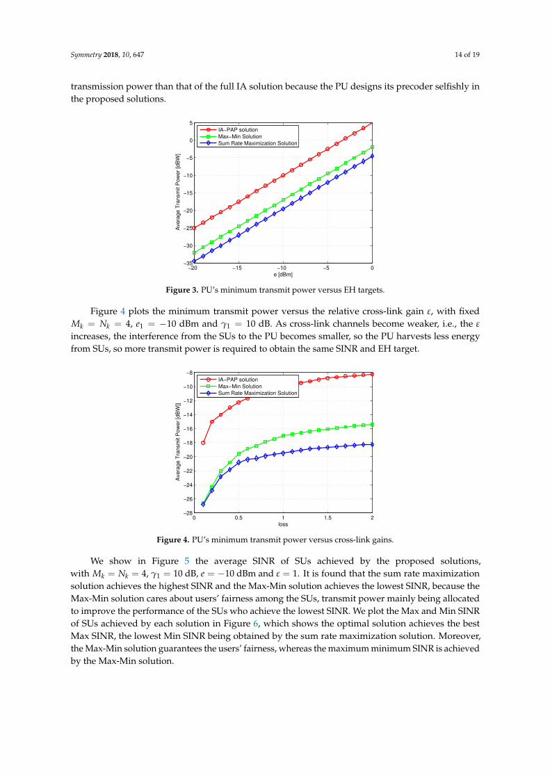
Next, we show in Figure 3 the minimum transmission power of the proposed solutions overe1 with fixed γ1 = 10 dB, M = N = 4 and ε = 1. In Figure 3 the optimal solution achieves theminimum PU transmission power. Furthermore, the proposed solutions achieve notably smaller
Symmetry 2018, 10, 647 14 of 19
transmission power than that of the full IA solution because the PU designs its precoder selfishly inthe proposed solutions.
−20 −15 −10 −5 0−35
−30
−25
−20
−15
−10
−5
0
5
e [dBm]
Ave
rage
Tra
nsm
it P
ow
er
[dB
W]
IA−PAP solution
Max−Min Solution
Sum Rate Maximization Solution
Figure 3. PU’s minimum transmit power versus EH targets.
Figure 4 plots the minimum transmit power versus the relative cross-link gain ε, with fixedMk = Nk = 4, e1 = −10 dBm and γ1 = 10 dB. As cross-link channels become weaker, i.e., the ε
increases, the interference from the SUs to the PU becomes smaller, so the PU harvests less energyfrom SUs, so more transmit power is required to obtain the same SINR and EH target.
0 0.5 1 1.5 2−28
−26
−24
−22
−20
−18
−16
−14
−12
−10
−8
loss
Ave
rag
e T
ran
sm
it P
ow
er
[dB
W]]
IA−PAP solution
Max−Min Solution
Sum Rate Maximization Solution
Figure 4. PU’s minimum transmit power versus cross-link gains.
We show in Figure 5 the average SINR of SUs achieved by the proposed solutions,with Mk = Nk = 4, γ1 = 10 dB, e = −10 dBm and ε = 1. It is found that the sum rate maximizationsolution achieves the highest SINR and the Max-Min solution achieves the lowest SINR, because theMax-Min solution cares about users’ fairness among the SUs, transmit power mainly being allocatedto improve the performance of the SUs who achieve the lowest SINR. We plot the Max and Min SINRof SUs achieved by each solution in Figure 6, which shows the optimal solution achieves the bestMax SINR, the lowest Min SINR being obtained by the sum rate maximization solution. Moreover,the Max-Min solution guarantees the users’ fairness, whereas the maximum minimum SINR is achievedby the Max-Min solution.

Symmetry 2018, 10, 647 15 of 19
−10 −5 0 5 100
5
10
15
20
25
30
35
40
45
e [dB]
Avera
ge S
INR
[dB
]
IA−PAP solution
Max−Min Solution
Sum Rate Maximization Solution
Figure 5. SUs’ average SINR versus EH targets.
−10 −5 0 5 100
10
20
30
40
50
60
70
80
e [dB]
Avera
ge S
INR
[dB
]
Max SINR−IA−PAP solution
Max SINR−Max−Min Solution
Max SINR−Sum Rate Maximization Solution
Min SINR−IA−PAP solution
Min SINR−Max−Min Solution
Min SINR−Sum Rate Maximization Solution
Figure 6. SUs’ Max SINR and Min SINR versus EH targets.
Finally, we provide numerical results to verify the fast convergence speed of the proposedsolutions. The average achievable SINR of both sum rate maximization and Max-Min solutions isdepicted as a function of iterations, with Mk = Nk = 4, γ1 = 10 dB, e = −10 dBm and ε = 1.In Figure 7 the proposed approaches converges in a few iterations. Our solutions indeed converge byiteration process.
0 5 10 15 200
5
10
15
20
25
30
Iterations
Avera
ge S
INR
[dB
]
Max−Min Solution
Sum Rate Maximization Solution
Figure 7. SU’s average SINR versus iterations.

Symmetry 2018, 10, 647 16 of 19
5. Conclusions
This paper studies the transceiver design and power allocation for SWIPT over MIMO CRnetworks. We solved the nonconvex problem by alternating optimization in which the problem wasdecoupled into several optimization problems. By reformulation, the transmission power at the PU isminimized by SDR, while satisfying SINR and harvested energy constraints of the PU. The transceiverand power allocation are iteratively optimized by convex optimization for sum rate maximization andMax-Min approaches. Simulation shows different influences of SINR thresholds, EH thresholds andthe cross-link interference on the performance of different solutions. The useful insights provided inthis paper may help future investigations in the following research directions:
• Robust design: This paper considers a perfect CSI among all users, thus extending the results inour work to the more general imperfect CSI case is an interesting topic.
• Massive MIMO: Massive MIMO is a promising technology in the 5G communication network,but more effort is needed to design the transceiver for a Massive MIMO case.
• Nonlinear energy harvesting model: In practice, the energy harvesting model is a nonlinearitymodel; in the near future, we will pay attention to transmission strategies design for nonlinearenergy harvesting model.
Author Contributions: writing—original draft preparation, F.W.; supervision, L.X.; funding acquisition, L.X. andD.Y.; writing—review and editing, L.C.; and project administration, X.L.
Funding: This research was funded by the National Natural Science Foundation of China under grant numbers61703197, 61561032 and 61461029.
Conflicts of Interest: The authors declare no conflict of interest.
Appendix A. Proof of the Proposition 1
Since the problem is convex and satisfies the Slater’s condition, it has zero duality gap.The Lagrangian of Equation (14) can be expressed as
L (X1, ρ1, λ1, µ1) , Tr(X1)
− λ1
(1
γ1UH
1 H11X1HH11U1 − σ2
1 −δ2
1ρ1
)
− µ1
(QSUs-PU − ‖H11X1HH
11‖ − σ21 −
e1
ζ1(1− ρ1)
) (A1)
where λ1 and µ1 denote the dual variables associated with the SINR constraint and harvestedenergy constraint of the problem in Equation (14), respectively. The dual function of the problem inEquation (14) is expressed as:
g (λ1, µ1) = minX1�0,0<ρ1<1
L (X1, ρ1, λ1, µ1) (A2)
This can be rewritten as
g (λ1, µ1) = minX1�0,0<ρ1<1
Tr(ΨX1) + (λ1 + µ1)σ21
+
[λ1δ2
1ρ1
+ µ1
(e2
1ζ1(1− ρ1)
−QSUs-PU
)] (A3)
whereΨ = IM −
λ1
γ1UH
1 H11HH11U1 − µ1H11HH
11 (A4)
Since the problem can be solved equivalently by solving the problem in Equation (A2), i.e., firstminimizing the Lagrangian to obtain the dual function with fixed λ1 > 0 and µ1 > 0, and then

Symmetry 2018, 10, 647 17 of 19
searching the optimal dual solutions λ∗1 and µ∗1 to maximize the dual function, the X∗1 and ρ∗1 thatmaximize the Lagrangian to obtain g(λ∗1 , µ1∗) are the optimal solution of Equation (14).
Let λ∗1 and µ∗1 denote the optimal dual solution, we define
Ψ∗ = IM −λ∗1γ1
UH1 H11HH
11U1 − µ∗1H11HH11 (A5)
It is observed from Equation (A3) that X1 and ρ1 are decoupled with each other, hence X∗1 must bea solution to the following problem:
minX1�0
Tr(Ψ∗X1) (A6)
To guarantee a bounded dual optimal value, we must have
Ψ∗ � 0 (A7)
As a result, the optimal value of problem is zero, i.e., Tr(Ψ∗X1) = 0; together with Ψ∗ � 0 andX1 � 0, it follows that:
Ψ∗X∗1 = 0 (A8)
Note that IM −λ∗1γ1
UH1 H11HH
11U1 is Hermitian and Positive Definite, hence Rank(IM −λ∗1γ1
UH1 H11HH
11U1) = M, and it follows that Rank(Ψ∗) ≥ M− 1. If Rank(Ψ∗) = M, from Equation (A8),
we have X∗1 = 0, i.e., the transmit power of PU is zero, which cannot be the optimal solution to theproblem. As a result, Rank(Ψ∗) = M− 1. From Equation (A8), we have Rank(X∗1) = 1 so the first partof proposition is thus proved.
Next, we consider the second part of Proposition 1.The optimal ρ∗1 can be found by solving thefollowing problem
min0<ρ1<1
λ∗1δ21
ρ1+ µ∗1
(e2
1ζ1(1− ρ1)
−QSUs-PU
)(A9)
It is observed from Equation (A9) that, ifλ∗1 = 0 and µ∗1 > 0, the optimal solution is ρ∗1 → 1.Besides, if λ∗1 > 0 and µ∗1 = 0, the optimal solution is ρ∗1 → 0. However, for given γ1 > 0 and e1 > 0,these two cases cannot happen. Furthermore, if λ∗1 = 0 and µ∗1 = 0, we have Ψ∗ = IM, which turnsto X∗1 = 0, hence λ∗1 = 0 and µ∗1 = 0 cannot be true. In conclusion, the optimal dual variablesshould satisfy λ∗1 > 0 and µ∗1 > 0, according to the complementary slackness [36]; the second part ofProposition 1 is thus proved. Combing the proofs of both parts, the Proposition 1 is proved.
References
1. Valtchev, S.; Borge, B.V.; Brandisky, K.; Klaassens, J.B. Efficient Resonant Inductive Coupling Energy TransferUsing New Magnetic and Design Criteria. In Proceedings of the 2005 IEEE 36th Power Electronics SpecialistsConference, Recife, Brazil, 16 June 2005; pp. 1293–1298.
2. Liu, H. Maximizing Efficiency of Wireless Power Transfer with Resonant Inductive Coupling. 2011. Availableonline: http://hxhl95.github.io/media/ib_ee.pdf (accessed on 16 October 2018).
3. Kurs, A.; Karalis, A.; Moffatt, R.; Joannopoulos, J.D.; Fisher, P.; Soljacic, M. Wireless power transfer viastrongly coupled magnetic resonances. Science 2007, 317, 83–86. [CrossRef] [PubMed]
4. Jonah, O.; Georgakopoulos, S.V. Wireless Power Transfer in Concrete via Strongly Coupled MagneticResonance. IEEE Trans. Antennas Propag. 2013, 61, 1378–1384. [CrossRef]
5. Varshney, L.R. Transporting information and energy simultaneously. In Proceedings of the 2008 IEEEInternational Symposium on Information Theory, Toronto, ON, Canada, 6–11 July 2008; pp. 1612–1616.
6. Lu, X.; Wang, P.; Niyato, D.; Kim, D.I.; Han, Z. Wireless Networks with RF Energy Harvesting:A Contemporary Survey. IEEE Commun. Surv. Tutor. 2015, 17, 757–789. [CrossRef]

Symmetry 2018, 10, 647 18 of 19
7. Yang, D.; Wu, Q.; Zeng, Y.; Zhang, R. Energy Tradeoff in Ground-to-UAV Communication via TrajectoryDesign. IEEE Trans. Veh. Technol. 2018, 67, 6721–6726.
8. Zhang, R.; Ho, C.K. MIMO Broadcasting for Simultaneous Wireless Information and Power Transfer.IEEE Trans. Wirel. Commun. 2013, 12, 1989–2001. [CrossRef]
9. Liu, L.; Zhang, R.; Chua, K.C. Wireless Information Transfer with Opportunistic Energy Harvesting.IEEE Trans. Wirel. Commun. 2013, 12, 288–300. [CrossRef]
10. Ng, D.W.K.; Lo, E.S.; Schober, R. Wireless Information and Power Transfer: Energy Efficiency Optimizationin OFDMA Systems. IEEE Trans. Wirel. Commun. 2013, 12, 6352–6370. [CrossRef]
11. Wen, Z.; Liu, X.; Zheng, S.; Guo, W. Joint Source and Relay Design for MIMO Two-Way Relay Networkswith SWIPT. IEEE Trans. Veh. Technol. 2018, 67, 822–826. [CrossRef]
12. Shi, Q.; Liu, L.; Xu, W.; Zhang, R. Joint Transmit Beamforming and Receive Power Splitting for MISO SWIPTSystems. IEEE Trans. Wirel. Commun. 2014, 13, 3269–3280. [CrossRef]
13. Wang, F.; Peng, T.; Huang, Y. Decentralized Robust Transceiver Designs for MISO SWIPT InterferenceChannel. IEEE Access 2018, 6, 4537–4546. [CrossRef]
14. Zong, Z.; Feng, H.; Yu, F.R.; Zhao, N.; Yang, T.; Hu, B. Optimal Transceiver Design for SWIPT in K-UserMIMO Interference Channels. IEEE Trans. Wirel. Commun. 2016, 15, 430–445. [CrossRef]
15. Zhao, M.; Cai, Y.; Shi, Q.; Hong, M.; Champagne, B. Joint Transceiver Designs for Full-Duplex K-Pair MIMOInterference Channel with SWIPT. IEEE Trans. Commun. 2017, 65, 890–905. [CrossRef]
16. Gomadam, K.; Cadambe, V.; Jafar, S. A distributed numerical approach to interference alignment andapplications to wireless interference networks. IEEE Trans. Inf. Theory 2011, 57, 3309–3322. [CrossRef]
17. Zhao, N.; Yu, F.R.; Leung, V.C.M. Wireless energy harvesting in interference alignment networks.IEEE Commun. Mag. 2015, 53, 72–78. [CrossRef]
18. Li, X.; Sun, Y.; Yu, F.R.; Zhao, N. Antenna selection and power splitting for simultaneous wirelessinformation and power transfer in interference alignment networks. In Proceedings of the 2014 IEEEGlobal Communications Conference, Austin, TX, USA, 8–12 December 2014; pp. 2667–2672.
19. Guo, J.; Zhao, N.; Yu, F.R.; Liu, X.; Leung, V.C.M. Exploiting Adversarial Jamming Signals for EnergyHarvesting in Interference Networks. IEEE Trans. Wirel. Commun. 2017, 16, 1267–1280. [CrossRef]
20. Lunden, J.; Koivunen, V.; Huttunen, A.; Poor, H.V. Collaborative Cyclostationary Spectrum Sensing forCognitive Radio Systems. IEEE Trans. Signal Process. 2009, 57, 4182–4195. [CrossRef]
21. Lee, W.; Cho, D. Enhanced Spectrum Sensing Scheme in Cognitive Radio Systems with MIMO Antennae.IEEE Trans. Veh. Technol. 2011, 60, 1072–1085. [CrossRef]
22. Rossi, P.S.; Ciuonzo, D.; Romano, G. Orthogonality and Cooperation in Collaborative Spectrum Sensingthrough MIMO Decision Fusion. IEEE Trans. Wirel. Commun. 2013, 12, 5826–5836. [CrossRef]
23. Mohammad, F.R.; Ciuonzo, D.; Mohammed, Z.A.K. Mean-Based Blind Hard Decision Fusion Rules.IEEE Signal Process. Lett. 2018, 25, 630–634. [CrossRef]
24. Yang, Z.; Ding, Z.; Fan, P.; Karagiannidis, G.K. Outage Performance of Cognitive Relay Networks withWireless Information and Power Transfer. IEEE Trans. Veh. Technol. 2016, 65, 3828–3833. [CrossRef]
25. Zhou, F.; Li, Z.; Cheng, J.; Li, Q.; Si, J. Robust AN-Aided Beamforming and Power Splitting Design for SecureMISO Cognitive Radio with SWIPT. IEEE Trans. Wirel. Commun. 2017, 16, 2450–2464. [CrossRef]
26. Tuan, P.V.; Koo, I. Optimal Multiuser MISO Beamforming for Power-Splitting SWIPT Cognitive RadioNetworks. IEEE Access 2017, 5, 14141–14153. [CrossRef]
27. Xu, C.; Zhang, Q.; Li, Q.; Tan, Y.; Qin, J. Robust Transceiver Design for Wireless Information and PowerTransmission in Underlay MIMO Cognitive Radio Networks. IEEE Commun. Lett. 2014, 18, 1665–1668.[CrossRef]
28. Fang, B.; Qian, Z.; Zhong, W.; Shao, W. AN-Aided Secrecy Precoding for SWIPT in Cognitive MIMOBroadcast Channels. IEEE Commun. Lett. 2015, 19, 1632–1635. [CrossRef]
29. Yuan, Y.; Ding, Z. Outage Constrained Secrecy Rate Maximization Design with SWIPT in MIMO-CR Systems.IEEE Trans. Veh. Technol. 2018, 67, 5475–5480. [CrossRef]
30. Wu, F.; Xiao, L.; Yang, D.; Cuthbert, L.; Liu, X. Transceiver Designs for Interference Alignment BasedCognitive Radio Networks with Energy Harvesting. Wirel. Pers. Commun. 2018, 98, 1895–1911. [CrossRef]
31. Grant, M.; Boyd, S. CVX: Matlab Software for Disciplined Convex Programming, Version 2.0 Beta;CVX Research, Inc.: Austin, TX, USA, 2013.

Symmetry 2018, 10, 647 19 of 19
32. Rezaei, F.; Tadaion, A. Sum-Rate Improvement in Cognitive Radio Through Interference Alignment.IEEE Trans. Veh. Technol. 2016, 65, 145–154. [CrossRef]
33. Boshkovska, E.; Ng, D.W.K.; Zlatanov, N.; Schober, R. Practical Non-Linear Energy Harvesting Model andResource Allocation for SWIPT Systems. IEEE Commun. Lett. 2015, 19, 2082–2085. [CrossRef]
34. Clerckx, B.; Bayguzina, E. Waveform Design for Wireless Power Transfer. IEEE Trans. Signal Process. 2016,64, 6313–6328. [CrossRef]
35. Zeng, Y.; Clerckx, B.; Zhang, R. Communications and Signals Design for Wireless Power Transmission.IEEE Trans. Commun. 2017, 65, 2264–2290. [CrossRef]
36. Boyd, S.; Vandenberghe, L. Convex Optimization; Cambridge University Press: Cambridge, UK, 2004.
c© 2018 by the authors. Licensee MDPI, Basel, Switzerland. This article is an open accessarticle distributed under the terms and conditions of the Creative Commons Attribution(CC BY) license (http://creativecommons.org/licenses/by/4.0/).