trane product data convertible air handlers 1-1/2 - 5 ton ... · pdf file22-1879-1b-en 3...
TRANSCRIPT

August 2014 22-1879-1B-EN
Convertible Air Handlers1–1/2 — 5 TonTEM3A0B18S21SA
TEM3A0B24S21SA
TEM3A0B30S31SA
TEM3A0B36S31SA
TEM3A0C42S41SA
TEM3A0C48S41SA
TEM3A0C60S51SA
The TEM3 series air handler is designed for installation in a closet,utility room, alcove, basement, crawlspace or attic. These versatileunits are applicable to air conditioning and heat pumpapplications. Several models are available to meet the specificrequirements of the outdoor equipment. Field installed electricresistance heaters are available.
Product Data
2 22-1879-1B-EN
Features and Benefits. . . . . . . . . . . . . . . . . . . . . . . . . . . . . . . . . . . . . . . . . . . . . . . . . . . . . . . . . . . . . . . . . . . . . . . . . . . . . 3
Optional Equipment. . . . . . . . . . . . . . . . . . . . . . . . . . . . . . . . . . . . . . . . . . . . . . . . . . . . . . . . . . . . . . . . . . . . . . . . . . . . . 3
Product Specifications . . . . . . . . . . . . . . . . . . . . . . . . . . . . . . . . . . . . . . . . . . . . . . . . . . . . . . . . . . . . . . . . . . . . . . . . . . . . 4
Heater Pressure Drop Table TEM Air Handler Models . . . . . . . . . . . . . . . . . . . . . . . . . . . . . . . . . . . . . . . . . . . . . 6
Minimum Airflow CFM . . . . . . . . . . . . . . . . . . . . . . . . . . . . . . . . . . . . . . . . . . . . . . . . . . . . . . . . . . . . . . . . . . . . . . . . . . . 7
Performance and Electrical Data . . . . . . . . . . . . . . . . . . . . . . . . . . . . . . . . . . . . . . . . . . . . . . . . . . . . . . . . . . . . . . . . . . 8
TEM3 Air Handler and Heater Matrix Allowable Combinations. . . . . . . . . . . . . . . . . . . . . . . . . . . . . . . . . . . 12
Electrical Data . . . . . . . . . . . . . . . . . . . . . . . . . . . . . . . . . . . . . . . . . . . . . . . . . . . . . . . . . . . . . . . . . . . . . . . . . . . . . . . . . . . 13
Field Wiring. . . . . . . . . . . . . . . . . . . . . . . . . . . . . . . . . . . . . . . . . . . . . . . . . . . . . . . . . . . . . . . . . . . . . . . . . . . . . . . . . . . . . . 14
TEM Convertibility . . . . . . . . . . . . . . . . . . . . . . . . . . . . . . . . . . . . . . . . . . . . . . . . . . . . . . . . . . . . . . . . . . . . . . . . . . . . . . . 15
TEM3 Air Handler Dimensional Data . . . . . . . . . . . . . . . . . . . . . . . . . . . . . . . . . . . . . . . . . . . . . . . . . . . . . . . . . . . . . 16
Outline Drawing . . . . . . . . . . . . . . . . . . . . . . . . . . . . . . . . . . . . . . . . . . . . . . . . . . . . . . . . . . . . . . . . . . . . . . . . . . . . . . . . . 17
Table of Contents

22-1879-1B-EN 3
Features and Benefits• Painted metal cabinet with captured foil face insulation
• 2% or less air leakage
• R-4.2 Insulating Value
• Multi-Position UP/Down Flow, Horizontal Left /Right
• ALL Aluminum Coil with Enhanced Patented Coil Fin
• Electric Heaters with polarized plug connections (sold as accessory)
• R-410AThermal Expansion Valve
• ECMMotor ((55 TToonn MMooddeellss OOnnllyy))
• Low Voltage Pigtail Connections
• Draw Through Design
• Horizontal Drain pan
• Single Color
• Fused 24V Power
• 11 yyeeaarr wwaarrrraannttyy
• 1100--yyeeaarr wwaarrrraannttyy rreeggiisstteerreedd
• OOppttiioonnaall eexxtteennddeedd wwaarrrraannttyy aavvaaiillaabbllee
IImmppoorrttaanntt:: Condensate management kit is required for all 5 ton air handler models installed indownflow applications.
Optional EquipmentAccessory Number Description Fits Cabinet SizeBAYHTR1504BRK Electric Heater, 4KW, Breaker, 24V Control, 1 Ph 18.5” and 23.5”
BAYHTR1504PDC Electric Heater, 4KW, Pull Disconnect, 24V Control, 1 Ph 18.5” and 23.5”
BAYHTR1504LUG Electric Heater, 4KW, Lug, 24V Control, 1 Ph 18.5” and 23.5”
BAYHTR1505BRK Electric Heater, 5KW, Breaker, 24V Control, 1 Ph 18.5” and 23.5”
BAYHTR1505PDC Electric Heater, 5KW, Pull Disconnect, 24V Control, 1 Ph 18.5” and 23.5”
BAYHTR1505LUG Electric Heater, 5KW, Lug, 24V Control, 1 Ph 18.5” and 23.5”
BAYHTR1508BRK Electric Heater, 4KW, Breaker, 24V Control, 1 Ph 18.5” and 23.5”
BAYHTR1508PDC Electric Heater, 8KW, Pull Disconnect, 24V Control, 1 Ph 18.5” and 23.5”
BAYHTR1508LUG Electric Heater, 8KW, Lug, 24V Control, 1 Ph 18.5” and 23.5”
BAYHTR1510BRK Electric Heater, 10KW, Breaker, 24V Control, 1 Ph 18.5” and 23.5”
BAYHTR1510PDC Electric Heater, 10KW, Pull Disconnect, 24V Control, 1 Ph 18.5” and 23.5”
BAYHTR3510LUG Electric Heater, 10KW, Lug, 24V Control, 3 Ph 18.5” and 23.5”
BAYHTR3515LUG Electric Heater, 10KW, Lug, 24V Control, 3 Ph 18.5” and 23.5”
BAYHTR1515BRK Electric Heater, 15KW, Breaker, 24V Control, 1 Ph 18.5” and 23.5”
BAYHTR3515LUG Electric Heater, 15KW, Lug, 24V Control, 3 Ph 18.5” and 23.5”
BAYHTR1519BRK Electric Heater, 20KW, Breaker, 24V Control, 1 Ph 18.5” and 23.5”
BAYHTR1520BRK Electric Heater, 20KW, Breaker, 24V Control, 1 Ph 18.5”
BAYTEMSPFG1A Supply Duct Flange Kit 23.5”
BAYSPEKT201A Single Point Power Entry Kit 18.5” and 23.5”BAYTEMDFKT1A (a) Downflow Condensate Management Kit 23.5” (5 Ton only)
TAYBASE185 Air Handler Downflow Sub-Bases 18.5”TAYBASE235 (TAYBASE 100) Air Handler Downflow Sub-Bases 23.5”
(a) Required with all 5–ton air h andler models in downflow orientation.

4 22-1879-1B-EN
Product Specifications
MODEL TEM3A0B18S21SA TEM3A0B24S21SA TEM3A0B30S31SA TEM3A0B36S31SA
RATED VOLTS/PH/HZ 208-230/1/60 208-230/1/60 208-230/1/60 208-230/1/60
RATINGS(a) See O.D. Specifications See O.D. Specifications See O.D. Specifications See O.D. Specifications
INDOOR COIL — Type Plate Fin Plate Fin Plate Fin Plate Fin
Rows — F.P.I. 3 - 14 3 - 14 3 - 14 3 - 14
Face Area (sq. ft.) 4.37 4.37 4.37 4.37
Tube Size (in.) 3/8 3/8 3/8 3/8
Refrigerant Control TXV TXV TXV TXV
Drain Conn. Size (in.)(b) 3/4 NPT 3/4 NPT 3/4 NPT 3/4 NPT
DUCT CONNECTIONS See Outline Drawing See Outline Drawing See Outline Drawing See Outline Drawing
INDOOR FAN— Type Centrifugal Centrifugal Centrifugal Centrifugal
Diameter-Width (In.) 9 X 7 9 X 7 10 X 8 10 X 8
No. Used 1 1 1 1
Drive - No. Speeds Direct - 3 Direct - 3 Direct - 3 Direct - 3
CFM vs. in. w.g. See Fan PerformanceTable
See Fan PerformanceTable
See Fan PerformanceTable
See Fan Performance Table
No. Motors — H.P. 1 - 1/4 1 - 1/4 1 - 1/2 1 - 1/2
Motor Speed R.P.M. 1075 1075 1075 1075
Volts/Ph/Hz 208-230/1/60 208-230/1/60 208-230/1/60 208-230/1/60
F.L. Amps 1.3 1.3 2.5 2.5
FILTER
Filter Furnished? (c) No No No No
REFRIGERANT R-410A R-410A R-410A R-410A
Ref. Line Connections Brazed Brazed Brazed Brazed
Coupling or Conn. Size — in.Gas
3/4 3/4 3/4 3/4
Coupling or Conn. Size — in.Liq. 3/8 3/8 3/8 3/8
DIMENSIONS H x W x D H xW x D H xW x D H x W x D
Crated (In.) 46 x 21 x 24 46 x 21 x 24 46 x 21 x 24 46 x 21 x 24
Uncrated 45-1/8 x 18-1/2 x 21-1/8 45-1/8 x 18-1/2 x 21-1/8 45-1/8 x 18-1/2 x 21-1/8 45-31/8 x 18-1/2 x 21-1/8
WEIGHT
Shipping (Lbs.) / Net (Lbs.) 116/110 116/110 116/110 116/110
(a) These Air Handlers are A.H.R.I certified with various Split System Air Conditioners and Heat Pumps (AHRI STANDARD 210/240). Refer to the Split SystemOutdoor Unit Product Data Guides for performance data.
(b) 3/4” Male Plastic Pipe (Ref: ASTM 1785–76)(c) Remote filter required.

22-1879-1B-EN 5
MODEL TEM3A0C42S41SA TEM3A0C48S41SA TEM3A0C60S51SA
RATED VOLTS/PH/HZ 208-230/1/60 208-230/1/60 208-230/1/60
RATINGS(a) See O.D. Specifications See O.D. Specifications See O.D. Specifications
INDOOR COIL — Type Plate Fin Plate Fin Plate Fin
Rows — F.P.I. 3 - 14 3 - 14 4 - 14
Face Area (sq. ft.) 5.50 5.50 5.91
Tube Size (in.) 3/8 3/8 3/8
Refrigerant Control TXV TXV TXV
Drain Conn. Size (in.)(b) 3/4 NPT 3/4 NPT 3/4 NPT
DUCT CONNECTIONS See Outline Drawing See Outline Drawing See Outline Drawing
INDOOR FAN— Type Centrifugal Centrifugal Centrifugal
Diameter-Width (In.) 10 X 10 10 X 10 11 X 10
No. Used 1 1 1
Drive - No. Speeds Direct - 3 Direct - 3 Direct - 3 (c)
CFM vs. in. w.g. See Fan Performance Table See Fan Performance Table See Fan Performance Table
No. Motors — H.P. 1 - 1/2 1 - 1/2 1 - 3/4
Motor Speed R.P.M. 1075 1075 1050
Volts/Ph/Hz 208-230/1/60 208-230/1/60 208-230/1/60
F.L. Amps 2.6 2.6 6.3
FILTER
Filter Furnished? (d) No No No
REFRIGERANT R-410A R-410A R-410A
Ref. Line Connections Brazed Brazed Brazed
Coupling or Conn. Size — in. Gas 7/8 7/8 7/8
Coupling or Conn. Size — in. Liq. 3/8 3/8 3/8
DIMENSIONS H xW x D H xW x D H xW x D
Crated (In.) 52–1/2 x 26 x 24 52–1/2 x 26 x 24 52–1/2 x 26 x 24
Uncrated 51-3/8 x 23-1/2 x 21-1/8 51-3/8 x 23-1/2 x 21-1/8 51-3/8 x 23-1/2 x 21-1/8
WEIGHT
Shipping (Lbs.) / Net (Lbs.) 145/138 145/138 145/138
(a) These Air Handlers are A.H.R.I certified with various Split System Air Conditioners and Heat Pumps (AHRI STANDARD 210/240). Refer to the Split SystemOutdoor Unit Product Data Guides for performance data.
(b) 3/4” Male Plastic Pipe (Ref: ASTM 1785–76)(c) ECMmotor(d) Remote filter required.
PPrroodduucctt SSppeecciiffiiccaattiioonnss

6 22-1879-1B-EN
Heater Pressure Drop TableTEM Air Handler Models
AirflowCFM
Number of Racks Heater Racks
1 2 3 4 Heater Model No. of Racks
Air Pressure Drop — Inches W.G. BAYHTR1504 1
1800 0.02 0.04 0.06 0.14 BAYHTR1505 1
1700 0.02 0.04 0.06 0.14 BAYHTR1508 2
1600 0.02 0.04 0.06 0.13 BAYHTR1510 2
1500 0.02 0.04 0.06 0.12 BAYHTR3510 3
1400 0.02 0.04 0.06 0.12 BAYHTR1515 3
1300 0.02 0.04 0.05 0.11 BAYHTR3515 3
1200 0.01 0.04 0.05 0.10 BAYHTR1519 4
1100 0.01 0.03 0.05 0.09 BAYHTR1520 4
1000 0.01 0.03 0.04 0.09 BAYHTR1521 4
900 0.01 0.03 0.04 0.08
800 0.01 0.03
700 0.01 0.02
600 0.01 0.02

22-1879-1B-EN 7
Minimum Airflow CFM
TEM3A0B18S21SA, TEM3A0B24S21SA
Heater MinimumHeat Speed Tap
With Heat Pump Without Heat Pump
BAYHTR1504BRK, BAYHTR1504PDC, BAYHTR1504LUG,BAYHTR1505BRK, BAYHTR1505PDC, BAYHTR1505LUG Low Low
BAYHTR1508BRK, BAYHTR1508PDC, BAYHTR1508LUG,BAYHTR1510BRK, BAYHTR1510PDC, BAYHTR1510LUG,BAYHTR3510LUG
Low Low
TEM3A0B30S31SA, TEM3A0B36S31SA
Heater MinimumHeat Speed Tap
With Heat Pump Without Heat Pump
BAYHTR1504BRK, BAYHTR1504PDC, BAYHTR1504LUG,BAYHTR1505BRK, BAYHTR1505PDC, BAYHTR1505LUG Low Low
BAYHTR1508BRK, BAYHTR1508PDC, BAYHTR1508LUG,BAYHTR1510BRK, BAYHTR1510PDC, BAYHTR1510LUG,BAYHTR3510LUG
Low Low
BAYHTR1515BRK, BAYHTR3515LUG, BAYHTR1519BRK Low Low
TEM3A0C42S41SA, TEM3A0C48S41SA
Heater MinimumHeat Speed Tap
With Heat Pump Without Heat Pump
BAYHTR1504BRK, BAYHTR1504PDC, BAYHTR1504LUG,BAYHTR1505BRK, BAYHTR1505PDC, BAYHTR1505LUG Low Low
BAYHTR1508BRK, BAYHTR1508PDC, BAYHTR1508LUG,BAYHTR1510BRK, BAYHTR1510PDC, BAYHTR1510LUG,BAYHTR3510LUG
Low Low
BAYHTR1515BRK, BAYHTR3515LUG, BAYHTR1520BRK Low Low
TEM3A0C60S51SA
Heater MinimumHeat Speed Tap
With Heat Pump Without Heat Pump
BAYHTR1504BRK, BAYHTR1504PDC, BAYHTR1504LUG,BAYHTR1505BRK, BAYHTR1505PDC, BAYHTR1505LUG Low Low
BAYHTR1508BRK, BAYHTR1508PDC, BAYHTR1508LUG,BAYHTR1510BRK, BAYHTR1510PDC, BAYHTR1510LUG,BAYHTR3510LUG
Low Low
BAYHTR1515BRK, BAYHTR3515LUG, BAYHTR1520BRK Low Low
Low = Taps 1–3

8 22-1879-1B-EN
Performance and Electrical Data
Table 1. Air Flow Performance
TEM3AOB18S21SA, TEM3A0B24S21SA (a)
EXTERNAL STATIC(in w.g)
AIRFLOW
Speed Taps — 230 VOLTS Speed Taps — 208 VOLTS
High Med Low † High Med Low †
0.1 984 903 719 946 827 612
0.2 948 868 694 910 796 589
0.3 906 828 665 868 760 567
0.4 858 781 630 820 717 543
0.5 802 726 588 764 666 513
0.6 735 660 537 697 605
0.7 651 581 614 532
1. Values are with wet coil, no filter, and no heaters2. CFM Correction for dry coil = Add 3%3. † = Factory setting
(a) For the TEM3A0B24S21SA, the recommended speed tap is medium at 0.4” external static pressure.
Table 2. Electrical Data
TEM3A0B18S21SA, TEM3A0B24S21SA
Heater Model No.
No. ofCir-cuits/Phases
240 Volt 208 Volt
CapacityHeaterAmpsperCircuit
MinimumCircuitAmpacity
MaximumOverloadProtection
CapacityHeaterAmpsperCircuit
Mini-mumCircuitAmpaci-ty
MaximumOverloadProtectionkW BTUH kW BTUH
No Heater 1.3 * 2 15 1.3 * 2 15
BAYHTR1504BRKBAYHTR1504PDCBAYHTR1504LUG
1/1 3.84 13100 16.0 22 25 2.88 9800 13.8 19 20
BAYHTR1505BRKBAYHTR1505PDCBAYHTR1505LUG
1/1 4.80 16400 20.0 27 30 3.60 12300 17.3 23 25
BAYHTR1508BRKBAYHTR1508PDCBAYHTR1508LUG
1/1 7.68 26200 32.0 42 45 5.76 19700 27.7 36 40
BAYHTR1510BRKBAYHTR1510PDCBAYHTR1510LUG
1/1 9.60 32800 40.0 52 60 7.20 24600 34.6 45 45
BAYHTR3510LUG 1/3 9.60 32800 23.1 30 30 7.20 24600 20.0 26 30
* = Motor Amps

22-1879-1B-EN 9
Table 3. Air Flow Performance
TEM3AOB30S31SA (a) , TEM3AOB36S31SA (a) (b)
EXTERNAL STATIC(in w.g)
AIRFLOW
Speed Taps — 230 VOLTS Speed Taps — 208 VOLTS
High Med Low † High Med Low †
0.1 1461 1336 979 1406 1173 834
0.2 1404 1291 971 1352 1152 819
0.3 1344 1242 962 1295 1121 810
0.4 1281 1188 944 1234 1081 804
0.5 1214 1130 916 1169 1035 791
0.6 1142 1066 876 1100 981 768
0.7 1066 997 1026 920 732
1. Values are with wet coil, no filter, and no heaters2. CFM Correction for dry coil = Add 3%3. † = Factory setting
(a) For TEM3A0B30S31SA and TEM3A0B36S31SA in downlfow applications, airflow must not exceed 1200 cfm due to condensate blow off.(b) For TEM3AOB36S31SA, the recommended speed tap is medium at 0.4” external static pressure.
Table 4. Electrical Data
TEM3AOB30S31SA, TEM3AOB36S31SA
Heater Model No.No. ofCircuits/Phases
240 Volt 208 Volt
Capacity HeaterAmps perCircuit
MinimumCircuitAmpacity
MaximumOverloadProtection
Capacity HeaterAmps perCircuit
MinimumCircuitAmpacity
MaximumOverloadProtectionkW BTUH kW BTUH
No Heater 2.5 * 3 15 2.5 * 3 15
BAYHTR1504BRKBAYHTR1504PDCBAYHTR1504LUG
1/1 3.84 13100 16.0 23 25 2.88 9800 13.8 20 20
BAYHTR1505BRKBAYHTR1505PDCBAYHTR1505LUG
1/1 4.8 16400 20.0 28 30 3.6 12300 17.3 25 25
BAYHTR1508BRKBAYHTR1508PDCBAYHTR1508LUG
1/1 7.68 26200 32.0 43 45 5.76 19700 27.7 38 40
BAYHTR1510BRKBAYHTR1510PDCBAYHTR1510LUG
1/1 9.6 32800 40.0 53 60 7.2 24600 34.6 46 50
BAYHTR1515BRK-Circuit 1 (a)
2/19.6 32800 40.0 53 60 7.2 24600 34.6 46 50
BAYHTR1515BRK-Circuit 2 4.8 16400 20.0 25 25 3.6 12300 17.3 22 25
BAYHTR1519BRK-Circuit 1 (a)
2/19.6 32800 40.0 53 60 7.2 24600 34.6 46 50
BAYHTR1519BRK-Circuit 2 9.6 32800 40.0 50 50 7.2 24600 34.6 43 45
BAYHTR3510LUG 1/3 9.6 32800 23.1 32 35 7.2 24600 20.0 28 30
BAYHTR3515LUG 1/3 14.4 49200 34.6 3046 50 10.8 36900 30.0 40 40
BAYHTR1515BRKwith single circuitpower source kitBAYSPEKT201A
1/1 14.4 49200 60.0 83 90 10.8 36900 51.9 73 80
BAYHTR1519BRKwith single circuitpower source kitBAYSPEKT201A
1/1 19.2 65500 80.0 108 110 14.4 49200 69.2 94 100
* = Motor Amps
(a) MCA and MOP for circuit 1 contains the motor amps
PPeerrffoorrmmaannccee aanndd EElleeccttrriiccaall DDaattaa

10 22-1879-1B-EN
Table 5. Air Flow Performance
TEM3AOC42S41SA(a) , TEM3AOC48S41SA (a) (b)
EXTERNAL STATIC(in w.g)
AIRFLOW
Speed Taps — 230 VOLTS Speed Taps — 208 VOLTS
High Med Low † High Med Low †
0.1 1959 1704 1344 1786 1465 1154
0.2 1898 1675 1332 1748 1462 1126
0.3 1828 1631 1325 1697 1444 1108
0.4 1750 1574 1310 1633 1410 1095
0.5 1662 1504 1277 1557 1359 1076
0.6 1563 1420 1223 1468 1289 1039
0.7 1452 1321 1365
1. Values are with wet coil, no filter, and no heaters2. CFM Correction for dry coil = Add 3%3. † = Factory setting
(a) For TEM3A0C42S41SA and TEM3A0C48S41SA in downflow applications, airflow must not exceed 1600 cfm due to condensate blow off.(b) For TEM3A0C48S41SA, the recommended speed tap is medium at 0.4” external static pressure.
Table 6. Electrical Data
TEM3AOC42S41SA, TEM3AOC48S41SA
Heater Model No.No. ofCircuits/Phases
240 Volt 208 Volt
Capacity HeaterAmps perCircuit
MinimumCircuitAmpacity
MaximumOverloadProtection
Capacity HeaterAmps perCircuit
MinimumCircuitAmpacity
MaximumOverloadProtectionkW BTUH kW BTUH
No Heater 2.6 * 3 15 2.6 * 3 15
BAYHTR1504BRKBAYHTR1504PDCBAYHTR1504LUG
1/1 3.84 13100 16.0 23 25 2.88 9800 13.8 21 25
BAYHTR1505BRKBAYHTR1505PDCBAYHTR1505LUG
1/1 4.8 16400 20.0 28 30 3.6 12300 17.3 25 25
BAYHTR1508BRKBAYHTR1508PDCBAYHTR1508LUG
1/1 7.68 26200 32.0 43 45 5.76 19700 27.7 38 40
BAYHTR1510BRKBAYHTR1510PDCBAYHTR1510LUG
1/1 9.6 32800 40.0 53 60 7.2 24600 34.6 47 50
BAYHTR1515BRK-Circuit 1 (a)
2/19.6 32800 40.0 53 60 7.2 24600 34.6 47 50
BAYHTR1515BRK-Circuit 2
4.8 16400 20.0 25 25 3.6 12300 17.3 22 25
BAYHTR1520BRK-Circuit 1 (a)
2/19.6 32800 40.0 53 60 7.2 24600 34.6 47 50
BAYHTR1520BRK-Circuit 2 9.6 32800 40.0 50 50 7.2 24600 34.6 43 45
BAYHTR3510LUG 1/3 9.6 32800 23.1 32 35 7.2 24600 20.0 28 30
BAYHTR3515LUG 1/3 14.4 49200 34.6 46 50 10.8 36900 30.0 40 40
BAYHTR1515BRKwith single circuitpower source kitBAYSPEKT201A
1/1 14.4 49200 60.0 83 90 10.8 36900 51.9 73 80
BAYHTR1520BRKwith single circuitpower source kitBAYSPEKT201A
1/1 19.2 65500 80.0 108 110 14.4 49200 69.2 94 100
* = Motor Amps
(a) MCA and MOP for circuit 1 contains the motor amps.
PPeerrffoorrmmaannccee aanndd EElleeccttrriiccaall DDaattaa

22-1879-1B-EN 11
Table 7. Air Flow Performance
TEM3AOC60S51SA
EXTERNAL STATIC(in w.g)
AIRFLOW
Speed Taps — 208 – 230 VOLTS
High Med † Low
0.1 1954 1864 1780
0.2 1919 1827 1741
0.3 1885 1791 1704
0.4 1852 1756 1668
0.5 1821 1723 1633
0.6 1790 1691 1599
0.7 1761 1660 1567
1. Values are with wet coil, no filter, and no heaters2. CFM Correction for dry coil = Add 3%3. † = Factory Setting4. Low = Taps 1–3, Med = Tap 4, High = Tap 55. BAYTEMDFKT1Amust be used for downflow applications and airflow must not exceed 1800 cfm due to condensate blow off.
Table 8. Electrical Data
TEM3AOC60S51SA
Heater Model No.No. ofCircuits/Phases
240 Volt 208 Volt
Capacity HeaterAmps perCircuit
MinimumCircuitAmpacity
MaximumOverloadProtection
Capacity HeaterAmps perCircuit
MinimumCircuitAmpacity
MaximumOverloadProtectionkW BTUH kW BTUH
No Heater 6.3 * 8 15 6.3 * 8 15
BAYHTR1504BRKBAYHTR1504PDCBAYHTR1504LUG
1/1 3.84 13100 16.0 28 30 2.88 9800 13.8 25 25
BAYHTR1505BRKBAYHTR1505PDCBAYHTR1505LUG
1/1 4.8 16400 20.0 33 35 3.6 12300 17.3 30 30
BAYHTR1508BRKBAYHTR1508PDCBAYHTR1508LUG
1/1 7.68 26200 32.0 48 50 5.76 19700 27.7 42 45
BAYHTR1510BRKBAYHTR1510PDCBAYHTR1510LUG
1/1 9.6 32800 40.0 58 60 7.2 24600 34.6 51 60
BAYHTR1515BRK-Circuit 1 (a)
2/19.6 32800 40.0 58 60 7.2 24600 34.6 51 60
BAYHTR1515BRK-Circuit 2
4.8 16400 20.0 25 25 3.6 12300 17.3 22 25
BAYHTR1520BRK-Circuit 1 (a)
2/19.6 32800 40.0 58 60 7.2 24600 34.6 51 60
BAYHTR1520BRK-Circuit 2
9.6 32800 40.0 50 50 7.2 24600 34.6 43 45
BAYHTR3510LUG 1/3 9.6 32800 23.1 36 40 7.2 24600 20.0 32 35
BAYHTR3515LUG 1/3 14.4 49200 34.6 50 50 10.8 36900 30.0 44 45
BAYHTR1515BRKwith single circuitpower source kitBAYSPEKT201A
1/1 14.4 49200 60.0 83 90 10.8 36900 51.9 73 80
BAYHTR1520BRKwith single circuitpower source kitBAYSPEKT201A
1/1 19.2 65500 80.0 108 110 14.4 49200 69.2 94 100
* = Motor Amps
(a) MCA and MOP for circuit 1 contains the motor amps.
PPeerrffoorrmmaannccee aanndd EElleeccttrriiccaall DDaattaa

12 22-1879-1B-EN
TEM3 Air Handler and Heater MatrixAllowable Combinations
TEM3MINIMUMHEATER AIRFLOWCFM—HEATERMATRIX
Model No.
BAYHTR1504BRK *BAYHTR1504PDC *BAYHTR1504LUG*BAYHTR1505BRK *BAYHTR1505PDC *BAYHTR1505LUG *
BAYHTR1508BRK *BAYHTR1508PDC *BAYHTR1508LUG *BAYHTR1510BRK *BAYHTR1510PDC *BAYHTR1510LUG *BAYHTR3510LUG *
BAYHTR1515BRK *BAYHTR3515LUG *
BAYHTR1519BRK * BAYHTR1520BRK *
TEM3A0B18S21S * L / L L / L —— —— ——
TEM3A0B24S21S * L / L L / L —— —— ——
TEM3A0B30S31S * L / L L / L L / L L / L ——
TEM3A0B36S31S * L / L L / L L / L L / L ——
TEM3A0C42S41S * L / L L / L L / L —— L / L
TEM3A0C48S41S * L / L L / L L / L —— L / L
TEM3A0C60S51S *(a) L / L L / L L / L —— L / L
1. Cooling / HP Airflow
2. * = Followed by two digits
(a) Taps 1–3 = Low, Tap 4 = Med, Tap 5 = High

22-1879-1B-EN 13
Electrical Data
Figure 1. TEM3A0B18 — C48
Figure 2. TEM3A0C60

14 22-1879-1B-EN
Field Wiring
Figure 3. Field Wiring Diagrams
R
G
B
W1
W2
R
B
O
Y
X2
R
G
B/C
O
Y
W
HEAT PUMP SYSTEMS
Blue
2 4 VAC HOT
FAN
2 4 VAC Com m on
SOV
COOL/ HEAT1 st STAGE
HEATI NG2 n d STAGE
EMERGENC YHEAT
Thermostat Air Handler OutdoorUnit
Pink BlackW2Pink
White White
X2
AC SYSTEMS
R
G
B
W1
B
Y
R
G
B/C
Y
W
Blue
2 4 VAC HOT
FAN
2 4 VAC Com m on
COOLI NG
HEAT
Thermostat Air Handler OutdoorUnit
In AC systems for multiple stages of electric heat, jumper W1and W2 together if comfort control has only one stage of heat.

22-1879-1B-EN 15
TEM Convertibility
Figure 4. Multi-Position Air Handler* = No Internal Modifications Required.
Airfl owAirfl ow
Air
flo
w Upfl ow Condensate Drains
Refri gerant Connections
Ver tical Upfl ow*
Horizontal Right
Horizontal Left Condensate Drains
Airflo
w
Downfl ow Condensate Drains
Ver tical D ownfl ow
Horizontal Left*
Horizontal Right Condensate Drains
Refri gerant Connections
16 22-1879-1B-EN
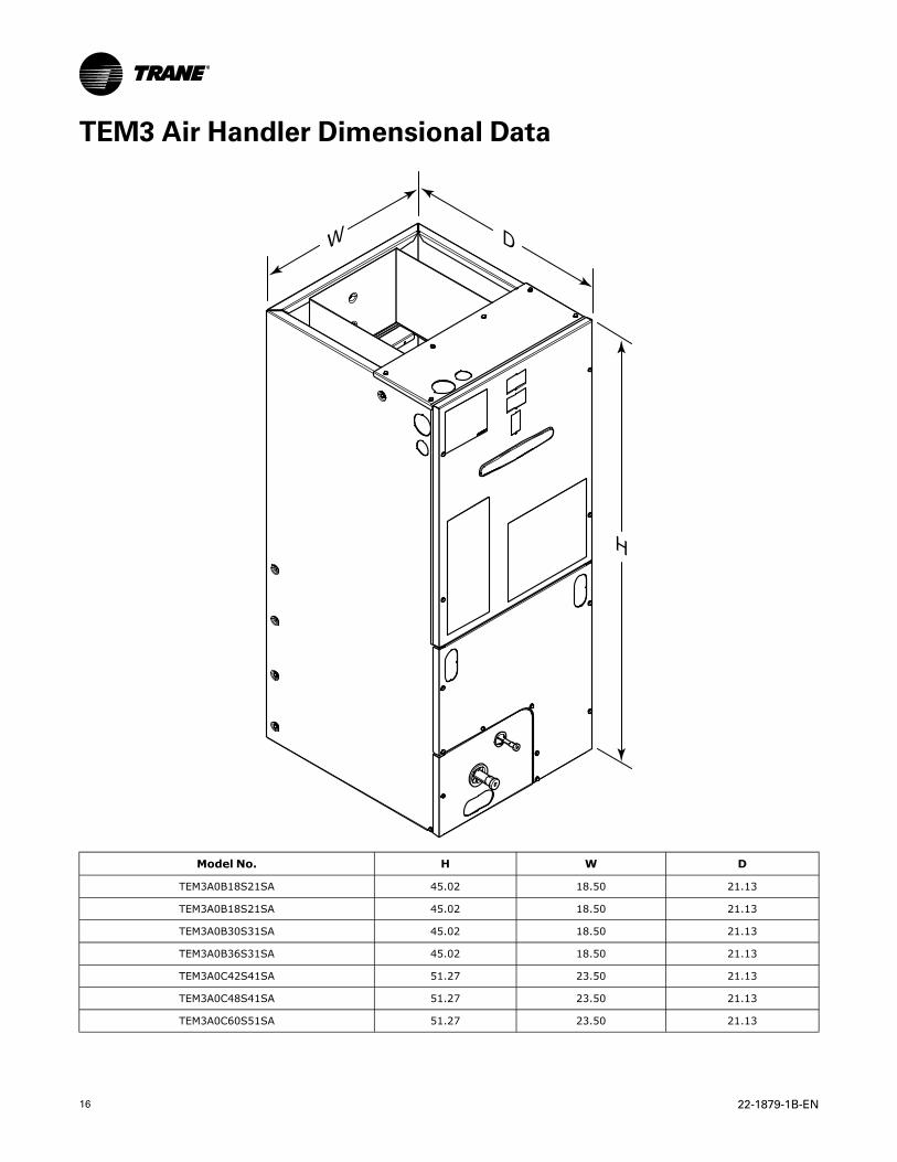
TEM3 Air Handler Dimensional Data
W
H
D
Model No. H W D
TEM3A0B18S21SA 45.02 18.50 21.13
TEM3A0B18S21SA 45.02 18.50 21.13
TEM3A0B30S31SA 45.02 18.50 21.13
TEM3A0B36S31SA 45.02 18.50 21.13
TEM3A0C42S41SA 51.27 23.50 21.13
TEM3A0C48S41SA 51.27 23.50 21.13
TEM3A0C60S51SA 51.27 23.50 21.13

22-1879-1B-EN 17
Outline Drawing
PRODUCT DIMENSIONS
Air Handler Model A B C D E F H FlowControl
Gas LineBraze
TEM3A0B18, 24, 30, 36 45.02 18.50 16.50 16.75 4.68 7.33 18.34 TXV 3/4
TEM3A0C42, 48, 60 51.27 23.50 21.50 21.75 7.01 9.66 24.59 TXV 7/8
All dimensions are in inches

18 22-1879-1B-EN
NNootteess

22-1879-1B-EN 19
NNootteess

NNootteess
Trane optimizes the performance of homes and buildings around the world. A business of Ingersoll Rand, the leader in
creating and sustaining safe, comfortable and energy efficient environments, Trane offers a broad portfolio of advanced
controls and HVAC systems, comprehensive building services, and parts. For more information, visit www.Trane.com.
Trane has a policy of continuous product and product data improvements and reserves the right to change design and specifications without notice.
©2014 Trane
22-1879-1B-EN 06 Aug 2014
Supersedes 22-1879-1A-EN (June 2014)