trak a.g.e. 2 set-up run math help prog in/out > soft keys select the mode of operation by...
TRANSCRIPT
SOUTHWESTERN INDUSTRIES, INC.
P. O. Box 9066 Compton, CA 90224-9066 Phn: (310) 608-4422 Fax: (310) 764-2668
Plant location: 2615 Homestead Place Rancho Dominguez, CA 90220-5610
TRAK A.G.E. 2
Version 2.0
Programming, Operating & Care Manual
Document: P/N 21038 Version: 010500

Copyright 2000, Southwestern Industries, Inc. All rights are reserved. No part of this publication may be reproduced, stored in a retrieval system, or transmitted, in any form or by any means, mechanical, photocopying, recording or otherwise, without the prior written permission of Southwestern Industries, Inc. While every effort has been made to include all the information required for the purposes of this guide, Southwestern Industries, Inc. assumes no responsibility for inaccuracies or omission and accepts no liability for damages resulting from the use of the information contained in this guide. All brand names and products are trademarks or registered trademarks of their respective holders. Southwestern Industries, Inc. 2615 Homestead Place Rancho Dominguez, CA 90224 Phn 310/608-4422 Fax 310/764-2668 Service Department Phn 800/367-3165 Fax 310/886-8029
_______________________ TABLE OF CONTENTS
Section
____________ 1.0 Introduction
1.1 Turning on the TRAK A.G.E. 2 1
Section
____________ 2.0 Description 2.1 Keyboard 3 2.2 Soft Keys 3 2.3 CRT Screen 4 2.4 Pendant Back Panel 4 2.5 Computer Cabinet 4 2.6 Encoders 4 2.7 Servo Motors/Amplifiers 5 2.8 Ball Screw Assembly 5 2.9 Emergency Stop Switch 5
Section
____________ 3.0 Definitions, Terms & Concepts 3.1 TRAK A.G.E. 2 Axis Conventions 9 3.2 Absolute & Incremental Reference 9 3.3 Referenced and Non-Referenced Data 10 3.4 Tool Diameter Compensation 10 3.5 Connective Events 12 3.6 Conrad 12

Section
____________ 4.0 DRO Mode 4.1 Enter DRO Mode 15 4.2 Clear Entry 15 4.3 Inch to MM or MM to Inch 16 4.4 Reset One Axis 16 4.5 Preset 16 4.6 Reset Absolute Reference 16 4.7 Preset Absolute Reference 16 4.8 Recall Absolute Position of All Axes 16 4.9 Recall Absolute Position of One Axis 17 4.10 Jog 17 4.11 Power Feed 17 4.12 Do One 18 4.13 Return to Absolute Zero 18 4.14 Teach 18
Section
____________ 5.0 Program Mode 5.1 Enter Program Mode and Assign a Part Number 21 5.2 Incremental Reference Position 22 5.3 CONRAD 22 5.4 Continue 23 5.5 Programming Strategy and Procedures 23 5.6 POSITION or DRILL Events 24 5.7 BOLT HOLE Events 25 5.8 MILL Events 26 5.9 ARC Events 27 5.10 A.G.E. Profile Mill 29 5.11 POCKET Event 36 5.12 FRAME Event 41 5.13 SUBROUTINE Events 44 5.14 Aborting a Partially Programmed Event 47 5.15 Editing Data While Programming an Event 47 5.16 LOOK 48 5.17 Finish Cuts 48 5.18 Do One Events 48 5.19 Program Sample 49 5.20 A.G.E. Program Sample 52

Section
____________ 6.0 Edit Mode 6.1 Enter Edit Mode 55 6.2 Recall and Data Correction 55 6.3 Adding an Event 56 6.4 Deleting an Event 57 6.5 Erasing a Program 57 6.6 Adding Teach to a Program 58 6.7 Editing A.G.E. Profiles 58
Section
____________ 7.0 Set Up Mode 7.1 Enter Set Up Mode 59 7.2 Inputting Tool Diameters 59 7.3 Draw Part Graphics 60 7.4 Tool Path Graphics 61 7.5 Service Codes 61
Section
____________ 8.0 Program Run Mode 8.1 Enter Run Mode 65 8.2 Starting to Run 65 8.3 Program Run 66 8.4 Program Run Messages 67 8.5 Stop 68 8.6 Feedrate Override 68 8.7 Trial Run 68 8.8 Data Errors 68 8.9 Fault Messages 69
Section
____________ 9.0 Math Help Mode 9.1 Procedure 71 9.2 Calculator-Math and Trig Procedures 73 9.3 Math Help Types 74
Section
____________ 10.0 Program In/Out Mode 10.1 Cautions About Storing and Retrieving Programs 76 10.2 Program Formats and Labeling 76 10.3 Enter Program In/Out Mode 77 10.4 Storing & Retrieving Programs from the TRAK A.G.E. 2 Built-In Floppy Disk Drive 77 10.5 Backing Up Your Programs 79 10.6 Storing & Retrieving Programs through the RS232 Port Including CAD/CAM Generated Programs 79
_________________________________________________________________ Southwestern Industries, Inc.
TRAK A.G.E. 2 Programming, Operating & Care Manual 1
1.0 INTRODUCTION Congratulations! Your TRAK A.G.E. 2 is a unique, one-of-a-kind, control system which combines the simplicity of manual machining with the contouring capability of CNC controls. The TRAK A.G.E. 2 has been designed to maximize the interplay between manual and automatic machining. It acts like an advanced digital readout in manual machine operation. It acts like a CNC when programmed to do complex contouring jobs. And it acts with the best qualities of each when your job is best done by transitioning back and forth between manual and contouring CNC operations with the powerful DO ONE routines. Section 2 of this manual provides a brief description of the TRAK A.G.E. 2. Section 3 defines some terms and concepts useful in learning to program and operate the TRAK A.G.E. 2. The TRAK A.G.E. 2 is organized into seven Modes of operation which are described in the following sections. Section 4 DRO: Digital Readout, jog, powerfeed, and simple DO ONE CNC operations. Section 5 PROGRAM: All input in simple machinist language. Section 6 EDIT: Program review and edit. Section 7 SET UP: Tool information and part graphics. Section 8 RUN: Machining the part. Section 9 MATH HELP: Sophisticated routines to automatically calculate points of intersection, tangency, etc. Section 10 PROGRAM IN/OUT: CAD/CAM interface, and program storage and retrieval
Southwestern Industries, Inc. TRAK A.G.E. 2 Programming, Operating & Care Manual
2
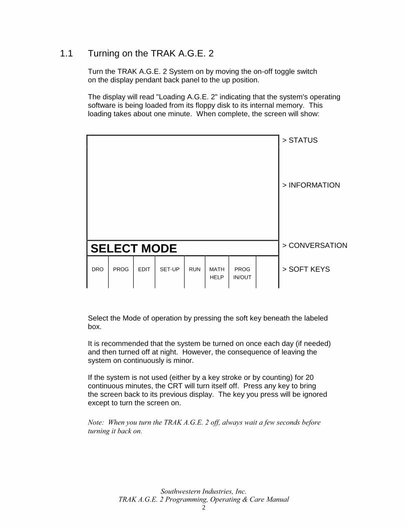
1.1 Turning on the TRAK A.G.E. 2 Turn the TRAK A.G.E. 2 System on by moving the on-off toggle switch on the display pendant back panel to the up position. The display will read "Loading A.G.E. 2" indicating that the system's operating software is being loaded from its floppy disk to its internal memory. This loading takes about one minute. When complete, the screen will show:
> STATUS
> INFORMATION
SELECT MODE > CONVERSATION
DRO
PROG
EDIT
SET-UP
RUN
MATH
HELP
PROG
IN/OUT
> SOFT KEYS
Select the Mode of operation by pressing the soft key beneath the labeled box. It is recommended that the system be turned on once each day (if needed) and then turned off at night. However, the consequence of leaving the system on continuously is minor. If the system is not used (either by a key stroke or by counting) for 20 continuous minutes, the CRT will turn itself off. Press any key to bring the screen back to its previous display. The key you press will be ignored except to turn the screen on. Note: When you turn the TRAK A.G.E. 2 off, always wait a few seconds before
turning it back on.

Southwestern Industries, Inc. TRAK A.G.E. 2 Programming, Operating & Care Manual
3
2.0 DESCRIPTION
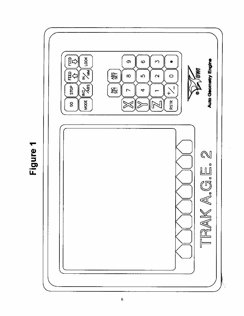
2.1 Keyboard (Figure 1)
GO: initiates motion in Run and Do One run
STOP: halts motion during Run or Do One run
FEED : feedrate override to increase feedrate
FEED : feedrate override to decrease feedrate
MODE: to change from one mode of operation to another
INC/ABS: switches all or one axis from incremental to absolute or absolute to incremental
IN/MM: causes English to Metric or Metric to English conversion of displayed data
LOOK : displays quick graphics in program mode
INC SET: loads incremental dimensions and general data
ABS SET: loads absolute dimensions and general data
X, Y, Z: selects axis for subsequent commands
RSTR (Restore): clears an entry, aborts a keying procedure
0-9, +/-, . : inputs numeric data with floating point format. Data is
automatically + unless +/- key is pressed. All input data is automatically rounded to the system's resolution.
2.2 Soft Keys Beneath the CRT screen are 8 keys which are not labeled. These keys are called software programmable or soft keys. A description of the function or use of each of these keys will be shown at the bottom of the CRT screen directly above each key. If, at any time, there is no description above a key, that key will not operate.

Southwestern Industries, Inc. TRAK A.G.E. 2 Programming, Operating & Care Manual
4
2.3 CRT Screen (Figure 1) The information displayed on the CRT screen is nearly always divided into 4 sections or areas. The top line, or status line, shows the system's current status. This includes the mode, inch or mm measurement, part numbers, and servo on or off status as applicable. Beneath the status line, and filling most of the screen, is the information area. Position data, program data, graphics, etc. are shown here. Beneath the information area is a single "conversation" line. All instructions, prompts, messages, etc. that the control needs to communicate to you are shown on this line. At the bottom of the CRT are boxes describing the current function or use of each soft key located under the box.
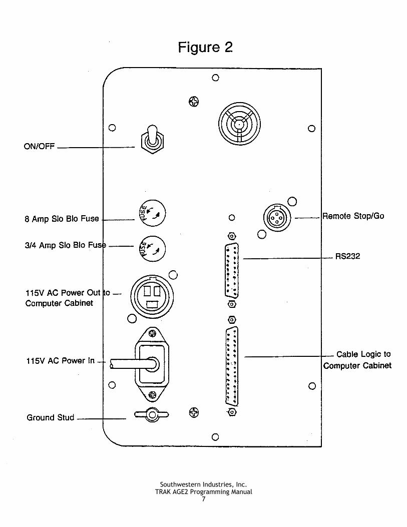
2.4 Pendant Back Panel (Figure 2) See Figure 2 for a description of the fuses, switches, and connectors on the pendant back panel.
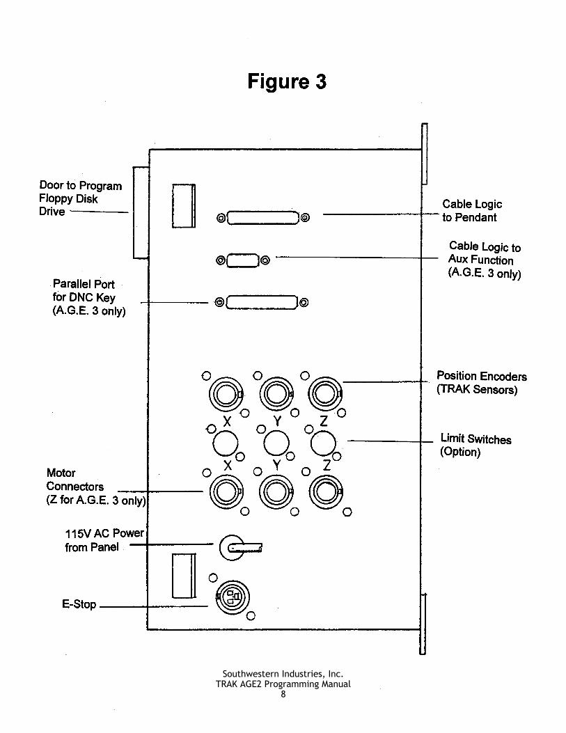
2.5 Computer Cabinet (Figure 3) The computer cabinet contains the TRAK A.G.E. 2 computer systems and access to the program floppy disk drive. See Figure 3 for a description of each connector.
2.6 Encoders The encoders used to provide direct table and quill position feedback to the TRAK A.G.E. 2 are sealed against typical shop environments and utilize the time proven gage-wheel principle. Model M250C is used on all axes.

Southwestern Industries, Inc. TRAK A.G.E. 2 Programming, Operating & Care Manual
5
2.7 Servo Motors/Amplifiers The TRAK A.G.E. 2 servo motor and amplifier have been combined into a single integrated package on each axis. The motors are rated 280 in-oz. maximum continuous torque which is sufficient for the heaviest cuts.
2.8 Ball Screw Assembly The normal acme leadscrews are replaced with zero backlash, ball bearing leadscrews to provide accurate positioning and precise contouring.
2.9 Emergency Stop Switch The emergency stop (E-stop) switch kills all power to the TRAK A.G.E. 2 servo motors. The computer and pendant remain powered.
6
Southwestern Industries, Inc.TRAK AGE2 Programming Manual
7
Southwestern Industries, Inc.TRAK AGE2 Programming Manual
8
_________________________________________________________________ Southwestern Industries, Inc.
TRAK A.G.E. 2 Programming, Operating & Care Manual
SECTION
____________ 3.0 _____________________________
Definitions, Terms & Concepts
Definitions, Terms & Concepts Section 3.0 | 9
3.0 DEFINITIONS, TERMS &
CONCEPTS
3.1 TRAK A.G.E. 2 Axis Conventions
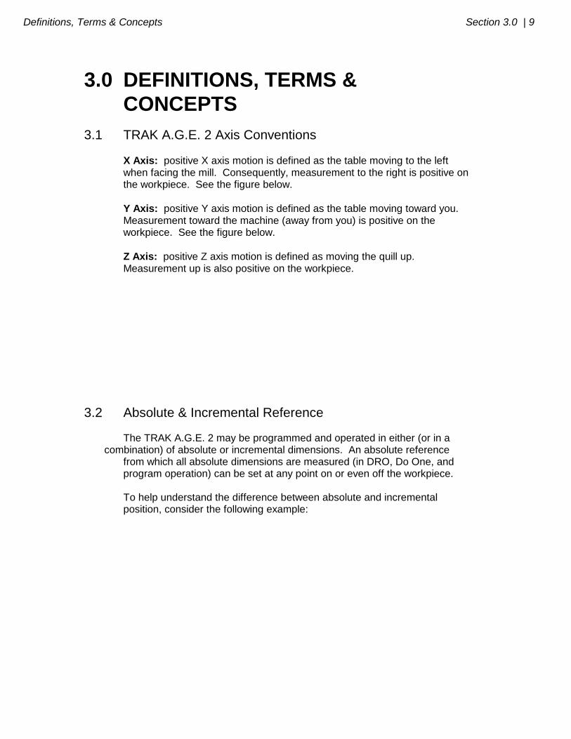
X Axis: positive X axis motion is defined as the table moving to the left when facing the mill. Consequently, measurement to the right is positive on the workpiece. See the figure below.
Y Axis: positive Y axis motion is defined as the table moving toward you. Measurement toward the machine (away from you) is positive on the workpiece. See the figure below.
Z Axis: positive Z axis motion is defined as moving the quill up. Measurement up is also positive on the workpiece.
3.2 Absolute & Incremental Reference The TRAK A.G.E. 2 may be programmed and operated in either (or in a combination) of absolute or incremental dimensions. An absolute reference from which all absolute dimensions are measured (in DRO, Do One, and program operation) can be set at any point on or even off the workpiece. To help understand the difference between absolute and incremental position, consider the following example:
10 | Section 3.0 Definitions, Terms & Concepts
3.3 Referenced and Non-Referenced Data Data is always loaded into the TRAK A.G.E. 2 by using the INC SET or ABS SET key. X, Y, Z positions are referenced data. In entering any X, Y, or Z position data, you must note whether it is an incremental or absolute dimension and enter it accordingly. All other information (non-referenced data), such as tool diameter, feedrate, etc. is not a position and may, therefore, be loaded with either the INC SET or ABS SET key. This manual uses the term SET when either INC SET or ABS SET may be used interchangeably.
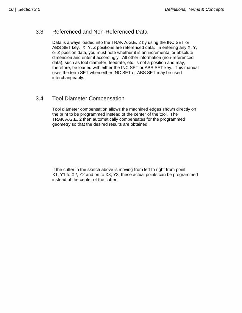
3.4 Tool Diameter Compensation Tool diameter compensation allows the machined edges shown directly on the print to be programmed instead of the center of the tool. The TRAK A.G.E. 2 then automatically compensates for the programmed geometry so that the desired results are obtained. If the cutter in the sketch above is moving from left to right from point X1, Y1 to X2, Y2 and on to X3, Y3, these actual points can be programmed instead of the center of the cutter.

Definitions, Terms & Concepts Section 3.0 | 11
Or, for the sketch above, the actual desired circle with radius R can be programmed instead of the radius of the center of the cutter Rc. Tool cutter compensation is always specified as the tool either right or left of the workpiece while looking in the direction of the tool motion. Following are examples of tool right: Examples of tool left are: Tool center means no compensation either right or left. That is, the centerline of the tool will be moved to the programmed points.
12 | Section 3.0 Definitions, Terms & Concepts
3.5 Connective Events Connective events occur between two milling events (either Mill or Arc) when the X, Y, and Z ending points of the first event are in the same location as the X, Y, and Z starting points of the next event. In addition, the tool offset and tool number of both events must be the same.
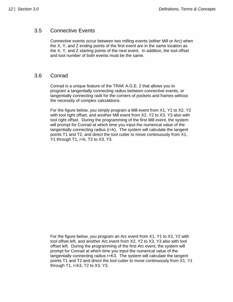
3.6 Conrad Conrad is a unique feature of the TRAK A.G.E. 2 that allows you to program a tangentially connecting radius between connective events, or tangentially connecting radii for the corners of pockets and frames without the necessity of complex calculations. For the figure below, you simply program a Mill event from X1, Y1 to X2, Y2 with tool right offset, and another Mill event from X2, Y2 to X3, Y3 also with tool right offset. During the programming of the first Mill event, the system will prompt for Conrad at which time you input the numerical value of the tangentially connecting radius (r=k). The system will calculate the tangent points T1 and T2, and direct the tool cutter to move continuously from X1, Y1 through T1, r=k, T2 to X3, Y3. For the figure below, you program an Arc event from X1, Y1 to X2, Y2 with tool offset left, and another Arc event from X2, Y2 to X3, Y3 also with tool offset left. During the programming of the first Arc event, the system will prompt for Conrad at which time you input the numerical value of the tangentially connecting radius r=K3. The system will calculate the tangent points T1 and T2 and direct the tool cutter to move continuously from X1, Y1 through T1, r=k3, T2 to X3, Y3.

Definitions, Terms & Concepts Section 3.0 | 13
Note: Conrad must always be the same as or larger than the tool radius for inside
corners. If conrad is less than the tool radius, and an inside corner is machined,
the TRAK A.G.E. 2 will ignore the Conrad.

_________________________________________________________________ Southwestern Industries, Inc.
TRAK A.G.E. 2 Programming, Operating & Care Manual
SECTION
____________ 4.0 _____________________________
DRO Mode
DRO Mode Section 4.0 | 15
4.0 DRO MODE The TRAK A.G.E. 2 operates in DRO Mode as a sophisticated 3-axis digital readout with jog, power feed capability, and singular Do One CNC events.
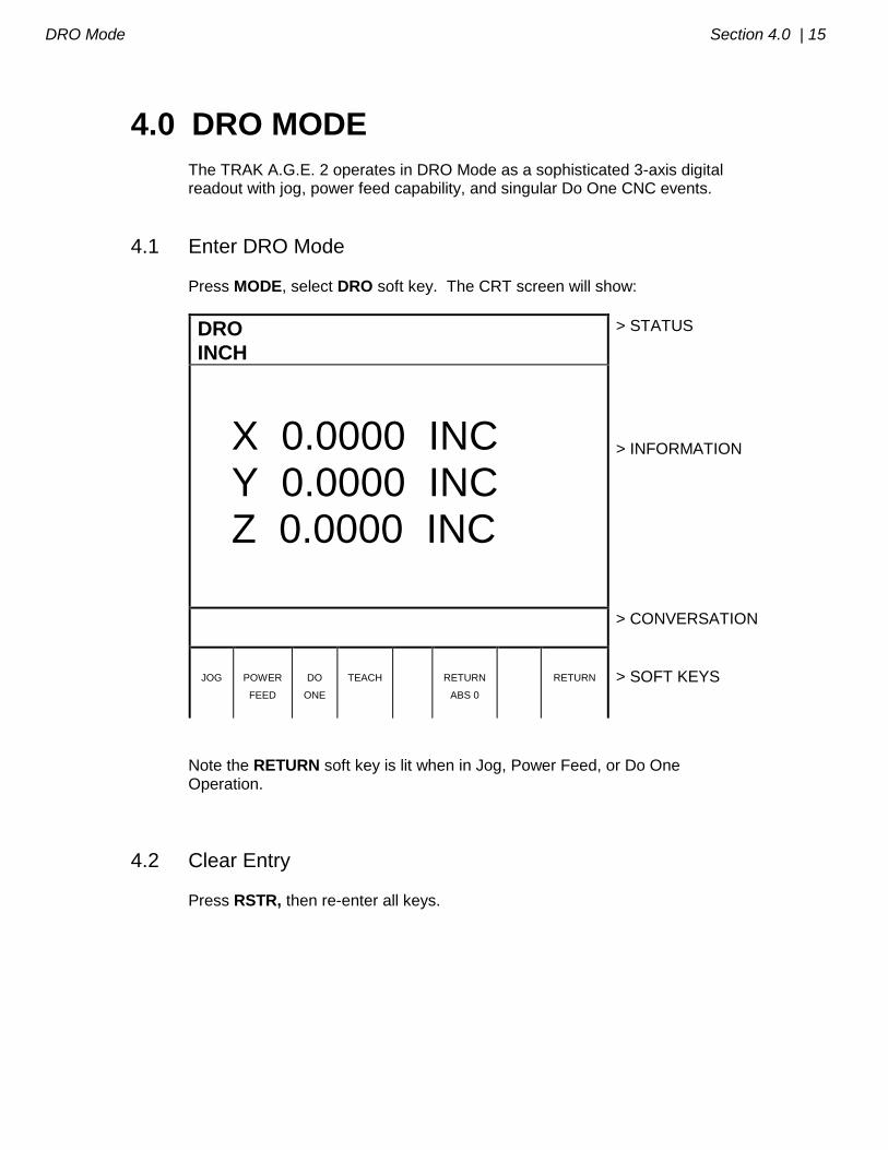
4.1 Enter DRO Mode
Press MODE, select DRO soft key. The CRT screen will show:
DRO
INCH
> STATUS
X 0.0000 INC Y 0.0000 INC Z 0.0000 INC
> INFORMATION
> CONVERSATION
JOG
POWER
FEED
DO
ONE
TEACH
RETURN
ABS 0
RETURN
> SOFT KEYS
Note the RETURN soft key is lit when in Jog, Power Feed, or Do One Operation.
4.2 Clear Entry
Press RSTR, then re-enter all keys.

16 | Section 4.0 DRO Mode
4.3 Inch to MM or MM to Inch
Press IN/MM and note CRT screen status line.
4.4 Reset One Axis Press X or Y or Z, INC SET. This zeros the incremental position in the selected axis.
4.5 Preset Press X or Y or Z, numeric data, INC SET to preset selected axis.
4.6 Reset Absolute Reference Press X or Y or Z, ABS SET to set selected axis absolute to zero at the current position. See 4.8 and 4.9 to display this data. Note: This will also reset the incremental dimension if the absolute position is being
displayed when it is reset.
4.7 Preset Absolute Reference Press X or Y or Z, numeric data, ABS SET to set the selected axis absolute to a preset location for the current machine position. See 4.8 and 4.9 to display this data. Note: This will also reset the incremental dimension if the absolute position is being
displayed when it is preset.
4.8 Recall Absolute Position of All Axes Press INC/ABS. Note the dimension for each axis is labeled INC or ABS.
DRO Mode Section 4.0 | 17
Press INC/ABS again to revert to the original reading.
4.9 Recall Absolute Position of One Axis
Press X or Y or Z, INC/ABS. Note the INC or ABS label for each axis. Repeat to get selected axis back to original reading.
4.10 Jog The servo motors can be used to jog the table.
a. Press the JOG soft key. b. The conversation line will read "JOG + 100 ipm" indicating the table will move in the X or Y positive direction at 100 inches per minute. This message will flash to warn you that JOG is activated.
c. Press +/- to reverse direction. The conversation display will read
"JOG - 100 ipm." Press +/- again to go back to JOG +.
d. Press FEED
to reduce the jog speed in 10 percent increments. The
conversation line will show these reductions. Press FEED to increase the speed.
e. Press and hold X or Y to jog that axis. Note the status line will indicate "SERVO ON." Release the key to stop. f. To jog at a prescribed rate, input the rate (for example, 25 for 25 inches
per minute) and press X or Y. Press FEED or FEED
to adjust. Press RSTR to return to 100 ipm. In metric this number represents the percent of the maximum, or 2540 mm/min.
g. Press RETURN soft key to return to manual DRO operation.
4.11 Power Feed The servo motors can be used as a power feed for the table or saddle.
a. Press the POWER FEED soft key.

18 | Section 4.0 DRO Mode
b. The conversation line will read "Power Feed 10 ipm" indicating the status and feed rate.
c. Press FEED or FEED
to adjust the feedrate from 1 ipm to 100 ipm.
d. Press X or Y, the dimension you wish to move to, and INC SET.
e. Press GO to begin power feed.
f. Press STOP to halt power feed for any reason. Press GO to resume. g. When the movement is complete, the status line will read "In Position." Repeat the process beginning at "c" above as often as you wish.
h. Press RETURN soft key to return to manual DRO operation.
4.12 Do One Because Do One operation is nearly identical to part programming it is described in Section 5.18.
4.13 Return to Absolute Zero At any time during manual DRO operation you may automatically move the
table to your absolute zero location in X and Y by pressing the RETURN
ABS 0 soft key. When you do, the conversation line will read "Check Z then
press GO." Make sure your tool is clear and press the GO key. When you do, the servos will turn on, move the table at rapid speed to your X and Y absolute zero position, and then turn off. You will be at zero and in manual DRO operation.
4.14 Teach The Teach function allows you to input a program into the TRAK A.G.E. 2 by remembering rapid position and feedrate milling events as you machine the first part, or portion of a part. This can be useful for simple operations like facing off a part, clearing out excess material, or remembering a few hole locations. While Teach can be useful, it is definitely not a substitute for programming the TRAK A.G.E. 2 (see Section 5) which is very simple, very powerful, and much more useful.
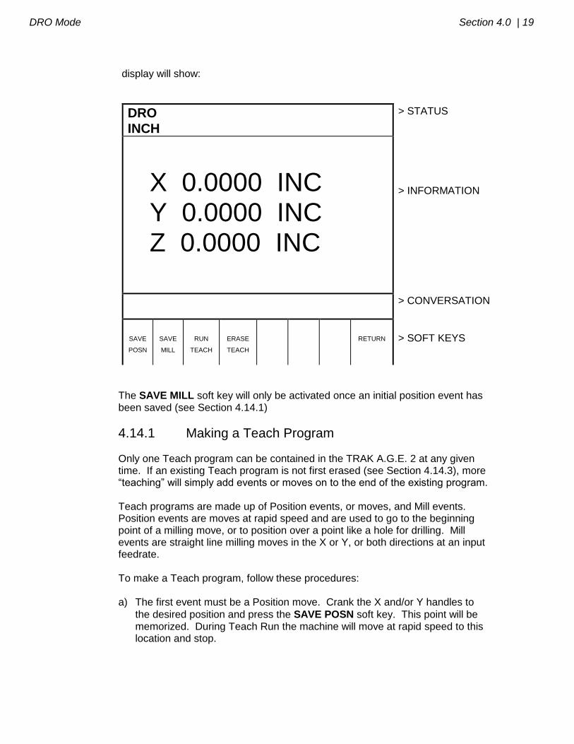
To enter Teach, press the TEACH soft key from the screen in Section 4.1. The
DRO Mode Section 4.0 | 19
display will show:
DRO
INCH
> STATUS
X 0.0000 INC Y 0.0000 INC Z 0.0000 INC
> INFORMATION
> CONVERSATION
SAVE
POSN
SAVE
MILL
RUN
TEACH
ERASE
TEACH
RETURN
> SOFT KEYS
The SAVE MILL soft key will only be activated once an initial position event has been saved (see Section 4.14.1)
4.14.1 Making a Teach Program
Only one Teach program can be contained in the TRAK A.G.E. 2 at any given time. If an existing Teach program is not first erased (see Section 4.14.3), more “teaching” will simply add events or moves on to the end of the existing program. Teach programs are made up of Position events, or moves, and Mill events. Position events are moves at rapid speed and are used to go to the beginning point of a milling move, or to position over a point like a hole for drilling. Mill events are straight line milling moves in the X or Y, or both directions at an input feedrate. To make a Teach program, follow these procedures: a) The first event must be a Position move. Crank the X and/or Y handles to
the desired position and press the SAVE POSN soft key. This point will be memorized. During Teach Run the machine will move at rapid speed to this location and stop.

20 | Section 4.0 DRO Mode
b) If you wish to rapid to the next location, repeat Step a. If you wish to feed or mill, go to Step c.
c) Mill the part along the X or Y (or both) path using the hand cranks. It’s not
important how you get to the end point. In Teach Run the machine will move at the programmed feedrate in a straight line from the beginning point to the
end. When at the end point, press the SAVE MILL soft key. The conversation line will prompt “Feedrate 10.0.” You may change the feedrate from the 10 inches per minute default to any value you wish through the
numeric keyboard. When the feedrate is what you want, press INC SET or
ABS SET to load into memory this position and feedrate. d) Repeat (a) or (c) above for all other rapid Position events, or feed Mill events
you wish. e) In Teach Run the machine will continue from one Mill event directly along to
the next Mill event. You must program a SAVE POSN if you want the machine to stop.
f) All events will automatically be saved with Tool Number 99. g) All Mill events will be saved with TOOL Center Offset (see Section 3.4).
4.14.2 Running a Teach Program A Teach Program may be run by itself from the DRO Mode, or added to a regular program (see Section 6.6), and run in the normal Run Mode.
To run a Teach program, press the RUN TEACH soft key from the screen in Section 4.14 above. Follow the same procedures for running a regular program as described in Section 8.3. Note: When you use Position to go to the beginning of a Mill move, you will have to hit GO twice
to begin the milling move.
4.14.3 Erasing a Teach Program
The TRAK A.G.E. 2 may contain only one Teach Program. To input another, you must first erase the one that exists.
To do so: Press the ERASE TEACH soft key from the screen in Section 4.14,
then select the YES soft key.

_________________________________________________________________ Southwestern Industries, Inc.
TRAK A.G.E. 2 Programming, Operating & Care Manual
SECTION
____________ 5.0 _____________________________
Program Mode
Program Mode Section 5.0 | 22
5.0 PROGRAM MODE
5.1 Enter Program Mode and Assign a Part Number
Press MODE, select PROGRAM soft key. For a new program to be written, there cannot already be a program in the active or current program memory. If a program does not already exist when you enter the Program Mode, the conversation line will read "Program Part Number." Enter the part number
(up to 8 digits) and press INC SET or ABS SET. Note: It is not necessary to enter a part number. If none is entered and the INC
SET or ABS SET button is pushed, the system will assume a part number 0.
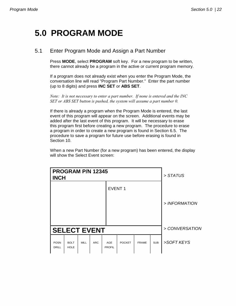
If there is already a program when the Program Mode is entered, the last event of this program will appear on the screen. Additional events may be added after the last event of this program. It will be necessary to erase this program first before creating a new program. The procedure to erase a program in order to create a new program is found in Section 6.5. The procedure to save a program for future use before erasing is found in Section 10. When a new Part Number (for a new program) has been entered, the display will show the Select Event screen:
PROGRAM P/N 12345
INCH
> STATUS
EVENT 1
> INFORMATION
SELECT EVENT > CONVERSATION
POSN
DRILL
BOLT
HOLE
MILL
ARC
AGE
PROFIL
FRAME
SUB
>SOFT KEYS
23 | Section 5.0 Program Mode
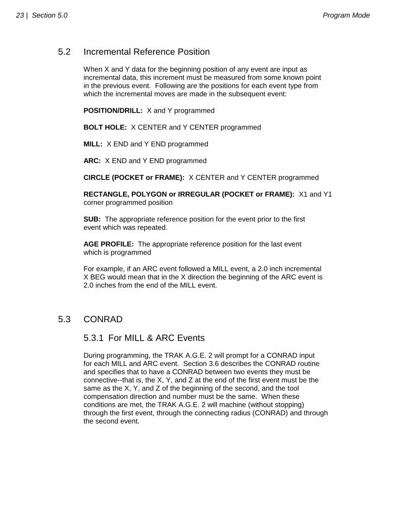
5.2 Incremental Reference Position When X and Y data for the beginning position of any event are input as incremental data, this increment must be measured from some known point in the previous event. Following are the positions for each event type from which the incremental moves are made in the subsequent event:
POSITION/DRILL: X and Y programmed
BOLT HOLE: X CENTER and Y CENTER programmed
MILL: X END and Y END programmed
ARC: X END and Y END programmed
CIRCLE (POCKET or FRAME): X CENTER and Y CENTER programmed
RECTANGLE, POLYGON or IRREGULAR (POCKET or FRAME): X1 and Y1 corner programmed position
SUB: The appropriate reference position for the event prior to the first event which was repeated.
AGE PROFILE: The appropriate reference position for the last event which is programmed For example, if an ARC event followed a MILL event, a 2.0 inch incremental X BEG would mean that in the X direction the beginning of the ARC event is 2.0 inches from the end of the MILL event.
5.3 CONRAD
5.3.1 For MILL & ARC Events During programming, the TRAK A.G.E. 2 will prompt for a CONRAD input for each MILL and ARC event. Section 3.6 describes the CONRAD routine and specifies that to have a CONRAD between two events they must be connective--that is, the X, Y, and Z at the end of the first event must be the same as the X, Y, and Z of the beginning of the second, and the tool compensation direction and number must be the same. When these conditions are met, the TRAK A.G.E. 2 will machine (without stopping) through the first event, through the connecting radius (CONRAD) and through the second event.
Program Mode Section 5.0 | 24
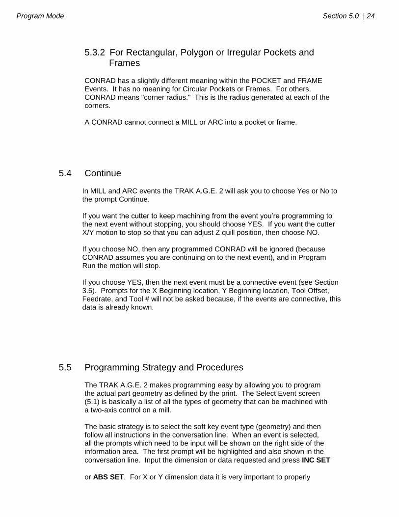
5.3.2 For Rectangular, Polygon or Irregular Pockets and Frames CONRAD has a slightly different meaning within the POCKET and FRAME Events. It has no meaning for Circular Pockets or Frames. For others, CONRAD means "corner radius." This is the radius generated at each of the corners. A CONRAD cannot connect a MILL or ARC into a pocket or frame.
5.4 Continue
In MILL and ARC events the TRAK A.G.E. 2 will ask you to choose Yes or No to the prompt Continue. If you want the cutter to keep machining from the event you’re programming to the next event without stopping, you should choose YES. If you want the cutter X/Y motion to stop so that you can adjust Z quill position, then choose NO. If you choose NO, then any programmed CONRAD will be ignored (because CONRAD assumes you are continuing on to the next event), and in Program Run the motion will stop. If you choose YES, then the next event must be a connective event (see Section 3.5). Prompts for the X Beginning location, Y Beginning location, Tool Offset, Feedrate, and Tool # will not be asked because, if the events are connective, this data is already known.
5.5 Programming Strategy and Procedures The TRAK A.G.E. 2 makes programming easy by allowing you to program the actual part geometry as defined by the print. The Select Event screen (5.1) is basically a list of all the types of geometry that can be machined with a two-axis control on a mill. The basic strategy is to select the soft key event type (geometry) and then follow all instructions in the conversation line. When an event is selected, all the prompts which need to be input will be shown on the right side of the information area. The first prompt will be highlighted and also shown in the
conversation line. Input the dimension or data requested and press INC SET
or ABS SET. For X or Y dimension data it is very important to properly
25 | Section 5.0 Program Mode
select INC SET or ABS SET. For all other data either SET will do.
As data is being entered it will show in the conversation line. When SET, the data will be transferred to the information area, and the next prompt will be shown in the conversation line.
From the event data input screen you may press the DATA FWD or DATA
BACK soft keys to go back to edit any data within an event. Simply shift forward or back to get the prompt in the conversation line and reinput the data. At any time before the event is complete you may cancel the event by pressing
the ABORT EVENT soft key. When all data for an event has been entered, the entire event will be shifted to the left side of the screen and the conversation line will ask you to select the next event.
5.5.1 Assumed Tool Offset, Feedrate, and Tool # The TRAK A.G.E. 2 will automatically program the following when the SET key is pressed without any other input:
TOOL OFFSET: for a Mill or Arc Event, same as the last event if that event was a Mill or Arc event
FEEDRATE: same as last event if that event was a Mill, Arc, Pocket, or Frame
TOOL #: same as last event You may change these assumed inputs by simply inputting the desired data when the event is programmed.
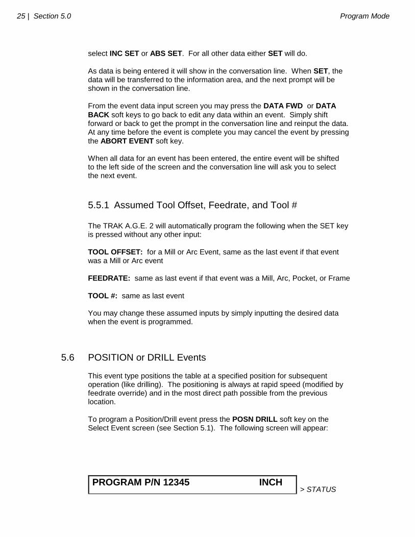
5.6 POSITION or DRILL Events This event type positions the table at a specified position for subsequent operation (like drilling). The positioning is always at rapid speed (modified by feedrate override) and in the most direct path possible from the previous location.
To program a Position/Drill event press the POSN DRILL soft key on the Select Event screen (see Section 5.1). The following screen will appear:
PROGRAM P/N 12345 INCH > STATUS
Program Mode Section 5.0 | 26
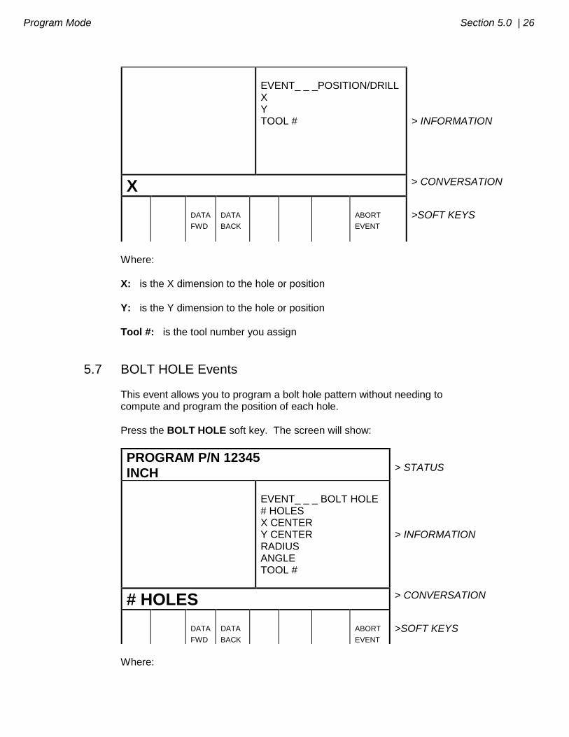
EVENT_ _ _POSITION/DRILL X Y TOOL #
> INFORMATION
X > CONVERSATION
DATA
FWD
DATA
BACK
ABORT
EVENT
>SOFT KEYS
Where:
X: is the X dimension to the hole or position
Y: is the Y dimension to the hole or position
Tool #: is the tool number you assign
5.7 BOLT HOLE Events This event allows you to program a bolt hole pattern without needing to compute and program the position of each hole.
Press the BOLT HOLE soft key. The screen will show:
PROGRAM P/N 12345
INCH
> STATUS
EVENT_ _ _ BOLT HOLE # HOLES X CENTER Y CENTER RADIUS ANGLE TOOL #
> INFORMATION
# HOLES > CONVERSATION
DATA
FWD
DATA
BACK
ABORT
EVENT
>SOFT KEYS
Where:

27 | Section 5.0 Program Mode
# HOLES: is the number of holes in the bolt hole pattern
X Center: is the X dimension to the center of the hole pattern
Y Center: is the Y dimension to the center of the hole pattern
Radius: is the radius of the hole pattern from the center to the center of the holes
Angle: is the angle from the positive X axis (that is 3 o'clock) to any hole; positive angle is measured counterclockwise from 0.000 to 359.999 degrees
Tool #: is the tool number you assign
5.8 MILL Events This event allows you to mill in a straight line from any one XY point to another, including at a diagonal. It may be programmed with a CONRAD if it is connective with the next event.
Press the MILL soft key. The screen will show:
PROGRAM P/N 12345
INCH
> STATUS
EVENT_ _ _ MILL X BEGIN Y BEGIN X END Y END CONRAD TOOL OFFSET FEEDRATE CONTINUE TOOL #
> INFORMATION
X BEGIN > CONVERSATION
DATA
FWD
DATA
BACK
ABORT
EVENT
>SOFT KEYS
Where:
Program Mode Section 5.0 | 28
X Begin: is the X dimension to the beginning of the mill cut
Y Begin: is the Y dimension to the beginning of the mill cut
X End: is the X dimension to the end of the mill cut; incremental is X Begin
Y End: is the Y dimension to the end of the mill cut; incremental is Y Begin
CONRAD: is the dimension of a tangential radius to the next event
Tool Offset: is the selection of the tool offset to right (input 1), offset to left (input 2), or tool center--no offset (input 0) relative to the programmed edge and direction of tool cutter movement
Feedrate: is the milling feedrate in in/min from .1 to 99.9, or mm/min from 5 to 2500
Continue: select if event is connective to the next (0=NO; 1=YES).
Note: If the previous event is programmed with a YES (1) for CONTINUE, then X
Begin, Y Begin, Tool Offset, Feedrate, and Tool # will not be prompted.
Tool #: is the tool number you assign
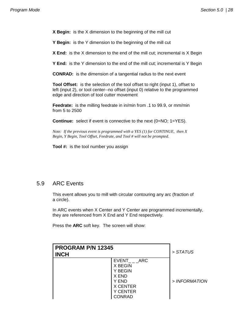
5.9 ARC Events This event allows you to mill with circular contouring any arc (fraction of a circle). In ARC events when X Center and Y Center are programmed incrementally, they are referenced from X End and Y End respectively.
Press the ARC soft key. The screen will show:
PROGRAM P/N 12345
INCH
> STATUS
EVENT_ _ _ARC X BEGIN Y BEGIN X END Y END X CENTER Y CENTER CONRAD
> INFORMATION
29 | Section 5.0 Program Mode
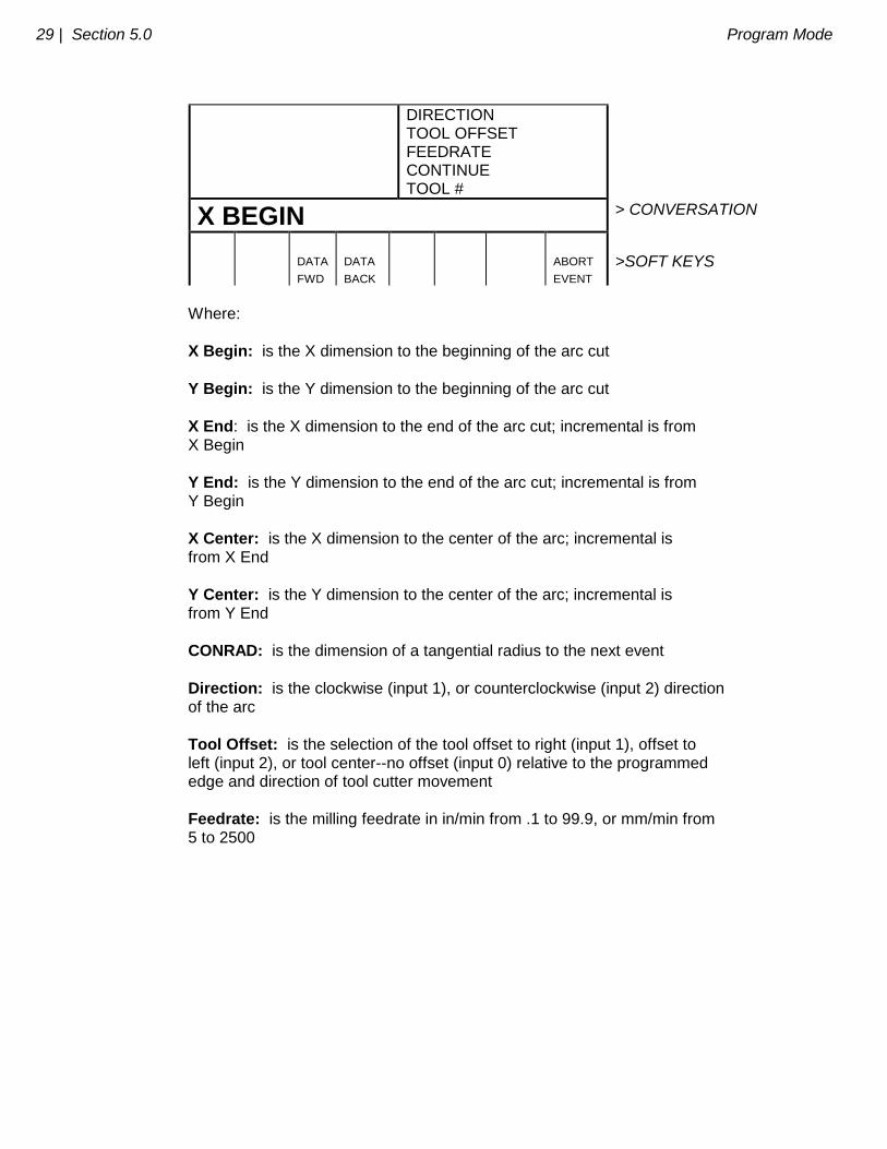
DIRECTION TOOL OFFSET FEEDRATE CONTINUE TOOL #
X BEGIN > CONVERSATION
DATA
FWD
DATA
BACK
ABORT
EVENT
>SOFT KEYS
Where:
X Begin: is the X dimension to the beginning of the arc cut
Y Begin: is the Y dimension to the beginning of the arc cut
X End: is the X dimension to the end of the arc cut; incremental is from X Begin
Y End: is the Y dimension to the end of the arc cut; incremental is from Y Begin
X Center: is the X dimension to the center of the arc; incremental is from X End
Y Center: is the Y dimension to the center of the arc; incremental is from Y End
CONRAD: is the dimension of a tangential radius to the next event
Direction: is the clockwise (input 1), or counterclockwise (input 2) direction of the arc
Tool Offset: is the selection of the tool offset to right (input 1), offset to left (input 2), or tool center--no offset (input 0) relative to the programmed edge and direction of tool cutter movement
Feedrate: is the milling feedrate in in/min from .1 to 99.9, or mm/min from 5 to 2500
Program Mode Section 5.0 | 30
Continue: select if event is connective to the next (0=NO; 1=YES).
Note: If the previous event is programmed with a YES (1) for CONTINUE, then X Begin, Y
Begin, Tool Offset, Feedrate, and Tool # will not be prompted.
Tool #: is the tool number you assign
5.10 A.G.E. Profile Mill
A Profile is a series of connected mill and arc events which form a path or shape. Remember, connective events are those where the end of one event coincides with the beginning of the next, and where the Z depth, tool offset, and tool number of both events are the same (see Section 3.5). Profiles can define an outside or inside shape. And it is not necessary that a profile end where it began. Obviously, any profile, as defined above, can be made by programming Mill and Arc events with a yes, CONTINUE as described in Sections 5.8 and 5.9. To do so, you always need to know the X, Y, begin, end and center points. However, many prints are drawn in such a way that these points are not known. You may use the Math Help functions described in Section 9 which, while powerful, are sometimes difficult and time consuming. The solution to this problem is the A.G.E. (Auto Geometry Engine) Profile Event which allows you to simply input the data that you do know (and in whatever form is on the drawing), guess at the X/Y Ends and Centers you don’t know and the A.G.E. will automatically calculate the data it needs. In other words, A.G.E. gives you some valuable capabilities of a CAD/CAM system in the easy-to-use TRAK A.G.E. 2 input format.
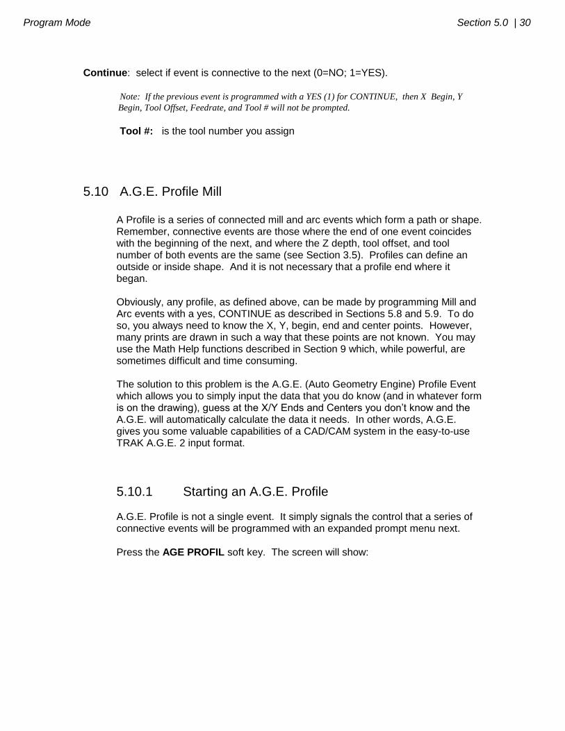
5.10.1 Starting an A.G.E. Profile A.G.E. Profile is not a single event. It simply signals the control that a series of connective events will be programmed with an expanded prompt menu next.
Press the AGE PROFIL soft key. The screen will show:
31 | Section 5.0 Program Mode
PROGRAM P/N 12345 INCH > STATUS
> INFORMATION
SELECT > CONVERSATION
MILL ARC ABORT
AGE
>SOFT KEYS
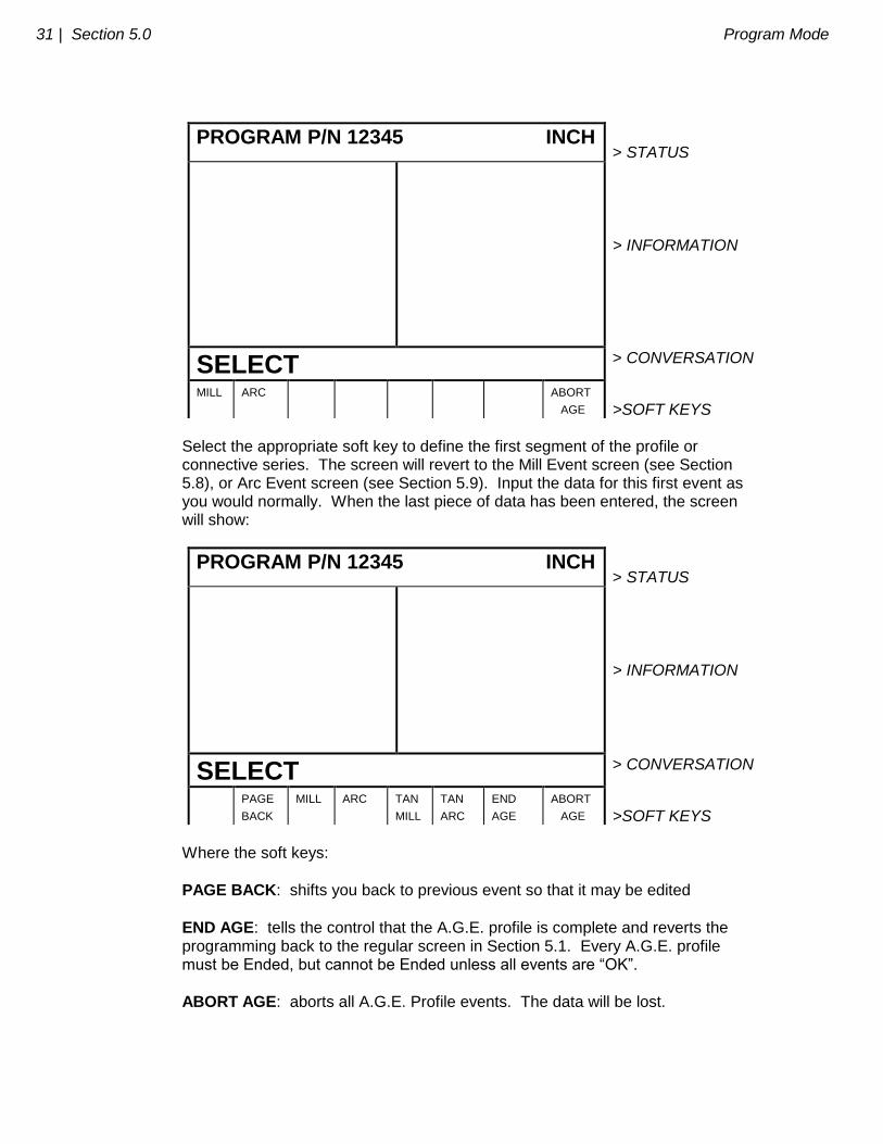
Select the appropriate soft key to define the first segment of the profile or connective series. The screen will revert to the Mill Event screen (see Section 5.8), or Arc Event screen (see Section 5.9). Input the data for this first event as you would normally. When the last piece of data has been entered, the screen will show:
PROGRAM P/N 12345 INCH > STATUS
> INFORMATION
SELECT > CONVERSATION
PAGE
BACK
MILL ARC TAN
MILL
TAN
ARC
END
AGE
ABORT
AGE
>SOFT KEYS
Where the soft keys:
PAGE BACK: shifts you back to previous event so that it may be edited
END AGE: tells the control that the A.G.E. profile is complete and reverts the programming back to the regular screen in Section 5.1. Every A.G.E. profile must be Ended, but cannot be Ended unless all events are “OK”.
ABORT AGE: aborts all A.G.E. Profile events. The data will be lost.

Program Mode Section 5.0 | 32
5.10.2 A.G.E. Profile Mill Events
Press MILL or TAN MILL from the screen above to program the next profile segment if it is a straight line. If the previous event was an arc, and this next
event is tangent to the arc, then select TAN MILL. Otherwise, select MILL. The screen will show:
PROGRAM P/N 12345 INCH > STATUS
EVENT_ _ _ TAN MILL X END Y END CONRAD ANGLE END LENGTH LINE ANGLE
> INFORMATION
X END > CONVERSATION
PAGE
FWD
PAGE
BACK
DATA
FWD
DATA
BACK
GUESS
HELP ABORT
EVENT
>SOFT KEYS
Where:
X END: is the X dimension to the end of the mill cut; incremental is X Begin
Y END: is the Y dimension to the end of the mill cut; incremental is Y Begin
CONRAD: is the dimension of a tangential radius to the next event
ANGLE END: is the angle measured counterclockwise from this mill event to the next. Do not input if the next event is an arc.
LENGTH: is the length of the mill from beginning to end
LINE ANGLE: is the angle of this mill line (moving from begin to end) measured counterclockwise from the positive X axis (that is, 3 o’clock)
Input the data (if it is known) as prompted and use the soft keys as follows:
PAGE FWD: to skip to the next event if there is one
PAGE BACK: to skip back to the previous event

33 | Section 5.0 Program Mode
DATA FWD: to skip down to the next prompt. If you don’t know the answer to
any prompt, use the DATA FWD (NEVER INC SET or ABS SET) to just skip it
DATA BACK: to skip up to the previous prompt
GUESS: press this when prompted for X End or Y End and you don’t know the dimension. Then input an estimate for the dimension (use absolute if possible)
and press ABS SET or INC SET. The dimension will be shown in parenthesis.
HELP: to see a diagram on the screen which defines the Mill and Tan Mill
prompts. Press RETURN to come back
ABORT EVENT: to cancel the event, but not the entire A.G.E. Profile Note: When enough information has been input to define the Mill segment, an “OK” will appear
next to the Event # and Type. When “OK’ there is no need to enter additional data. Press DATA
FWD (do not press PAGE FWD) past any remaining prompts. It is not necessary to make an
event “OK” before moving on to the next.
5.10.3 A.G.E. Profile Arc Events
Press the ARC or TAN ARC from the second screen in Section 5.10.1 to program the next profile segment if it is an arc. If this arc is tangent to the
previous MILL or ARC event, select TAN ARC. Otherwise, select ARC. The screen will show:
PROGRAM P/N 12345 INCH > STATUS
EVENT _ _ _ ARC DIRECTION X END Y END X CENTER Y CENTER CONRAD RADIUS CHORD LENGTH CHORD ANGLE
> INFORMATION
DIRECTION (1=CW, 2=CCW): > CONVERSATION
PAGE
FWD
PAGE
BACK
DATA
FWD
DATA
BACK
GUESS HELP ABORT
EVENT
>SOFT KEYS
Program Mode Section 5.0 | 34
Where:
DIRECTION: is the clockwise (input 1), or counterclockwise (input 2) direction of the arc
X END: is the X dimension to the end of the arc cut; incremental is from X Begin
Y END: is the Y dimension to the end of the arc cut; incremental is from Y Begin
X CENTER: is the X dimension to the center of the arc; incremental is from X End
Y CENTER: is the Y dimension to the center of the arc; incremental is from Y End
CONRAD: is the dimension of a tangential radius to the next event
RADIUS: is the radius of the arc
CHORD LENGTH: is the straight line distance from the begin point to the end point
CHORD ANGLE: is the angle spanned by the arc
Input the data (if it is known) as prompted and use the soft keys as follows:
PAGE FWD: to skip to the next event if there is one
PAGE BACK: to skip back to the previous event
DATA FWD: to skip down to the next prompt. If you don’t know the answer to
any prompt, use the DATA FWD (NEVER INC SET or ABS SET) to just skip it
DATA BACK: to skip up to the previous prompt
GUESS: press this when prompted for X End, Y End, X Center or Y Center and you don’t know the dimension. Then input an estimate for the dimension (use
absolute if possible) and press ABS SET or INC SET. The dimension will be shown in parenthesis.
HELP: to see a diagram on the screen which defines the Arc and Tan Arc
prompts. Press RETURN to come back
ABORT EVENT: to cancel the event, but not the entire A.G.E. Profile Note: When enough information has been input to define the Arc segment, an “OK” will appear
next to the Event # and Type. When “OK” there is no need to enter additional data. Press
35 | Section 5.0 Program Mode
DATA FWD past any remaining prompts. It is not necessary to make an event “OK” before
moving on to the next.
When you have programmed your last A.G.E. Profile line segment and they are
all “OK”, press the END AGE soft key. This signals the end of the profile shape and reverts the programming back to standard events in Section 5.1.
5.10.4 Procedures for Using A.G.E. Profile Events There are certain rules and issues which must be considered when programming A.G.E. Profile events. Specifically: a) The best strategy for using A.G.E. Profile is to input all the information you
have and guess at X/Y Ends and Centers when you don’t know them. The system will do the best it can using the guess dimensions to draw every event, so use LOOK (Section 5.16) to check if you’ve made an input error, or a really poor guess. If LOOK appears okay, keep programming. When you are finished with the profile and some events are still not “OK”, go back to them and see if there is more information you can input. If not, use Math Help (Section 9) to calculate some of the dimensions which you have guessed, and input the exact data (but not as a guess).
b) The first event of an A.G.E. Profile must be “OK.” That is, you must know
the beginning, end, and center points. If you don’t, then use a ramp on event from someplace off the profile (for begin), to a point you know on the profile (for end).
c) If all the events are “OK,” an “ALL OK” message will be shown in the Status
Line. If not on, then one or more previous events are not “OK”. When the conversation line prompts to select another event, all the “Not OK” events will be listed on the right side of the display.
d) If you do not know an X/Y End or Center, you do not have to guess---you can just skip it using the DATA FWD key. Sometimes your guess is not needed in calculating the correct information (for example, on a Mill if you input Length and Line Angle the system doesn’t need the guessed dimensions). However, most often this is not the case, and a reasonable guess is critical to calculating the points.
e) Whenever possible use absolute dimensions for guess.
f) Guessed dimensions are shown with parenthesis ( ) in the information area, and guess lines are bolder in LOOK.
g) The END AGE soft key will not end the A.G.E. Profile unless the events are “ALL OK.” If pressed before “ALL OK” the display will shift you back to the first not OK event.
Program Mode Section 5.0 | 36
h) NEVER, NEVER, NEVER use the ABS SET or INC SET key to data forward. This will input zero’s instead of skipping to the next prompt.
i) If you are not sure you know the correct answer to a prompt (for example,
angle end) just skip it. Input the next few events. If you don’t get “OK’s” then page back, study the print for additional information, do some calculations, and try to input some more data.
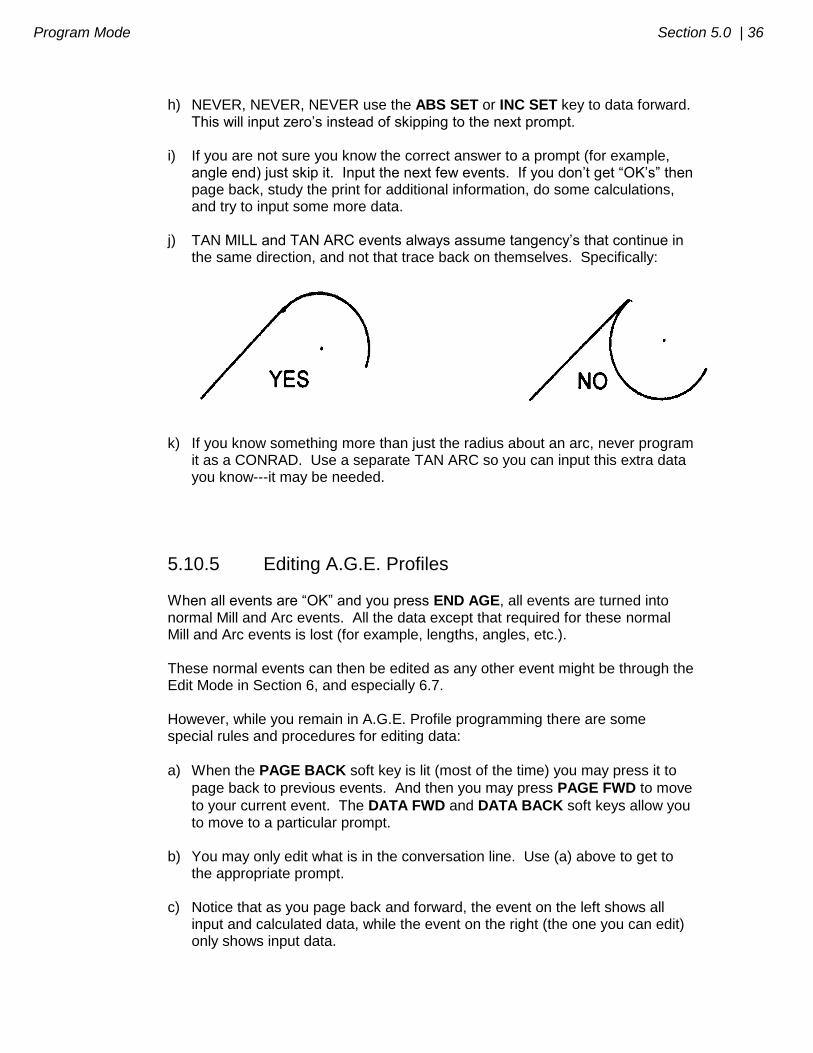
j) TAN MILL and TAN ARC events always assume tangency’s that continue in
the same direction, and not that trace back on themselves. Specifically:
k) If you know something more than just the radius about an arc, never program it as a CONRAD. Use a separate TAN ARC so you can input this extra data you know---it may be needed.
5.10.5 Editing A.G.E. Profiles
When all events are “OK” and you press END AGE, all events are turned into normal Mill and Arc events. All the data except that required for these normal Mill and Arc events is lost (for example, lengths, angles, etc.). These normal events can then be edited as any other event might be through the Edit Mode in Section 6, and especially 6.7. However, while you remain in A.G.E. Profile programming there are some special rules and procedures for editing data:
a) When the PAGE BACK soft key is lit (most of the time) you may press it to
page back to previous events. And then you may press PAGE FWD to move
to your current event. The DATA FWD and DATA BACK soft keys allow you to move to a particular prompt.
b) You may only edit what is in the conversation line. Use (a) above to get to
the appropriate prompt. c) Notice that as you page back and forward, the event on the left shows all
input and calculated data, while the event on the right (the one you can edit) only shows input data.
37 | Section 5.0 Program Mode
d) You may never edit calculated data, and the TRAK A.G.E. will not allow you to do so. If you move to a calculated prompt, the conversation line will read “calculated” and you may not edit it. If you could edit calculated data, you would create a redundant solution which would be impossible to run.
e) If you wish to input data for a prompt which has been calculated, you must
first erase data for another prompt which you have input and which was used to calculate the calculated prompt. To erase input data, bring its prompt to
the conversation line and press RSTR. Then go back to the prompt you wish to input to see if it is still calculated. If not, input the data you want.
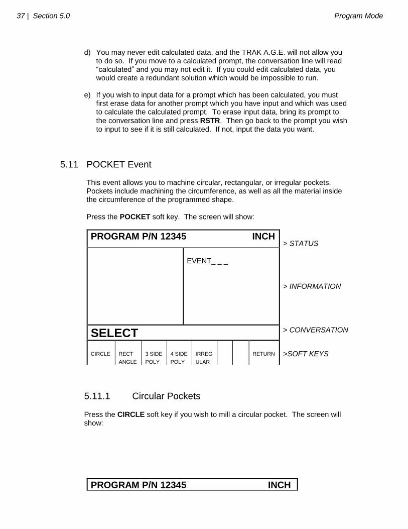
5.11 POCKET Event This event allows you to machine circular, rectangular, or irregular pockets. Pockets include machining the circumference, as well as all the material inside the circumference of the programmed shape.
Press the POCKET soft key. The screen will show:
PROGRAM P/N 12345 INCH > STATUS
EVENT_ _ _
> INFORMATION
SELECT > CONVERSATION
CIRCLE
RECT
ANGLE
3 SIDE
POLY
4 SIDE
POLY
IRREG
ULAR
RETURN
>SOFT KEYS
5.11.1 Circular Pockets
Press the CIRCLE soft key if you wish to mill a circular pocket. The screen will show:
PROGRAM P/N 12345 INCH

Program Mode Section 5.0 | 38
> STATUS
EVENT_ _ _ CIRCLE POCKET X CENTER Y CENTER RADIUS DIRECTION FIN CUT FEEDRATE TOOL #
> INFORMATION
X CENTER > CONVERSATION
DATA
FWD
DATA
BACK
ABORT
EVENT
>SOFT KEYS
Where:
X Center: is the X dimension to the center of the circle
Y Center: is the Y dimension to the center of the circle
Radius: is the finish radius of the circle
Direction: is the clockwise (input 1), or counterclockwise (input 2) direction for milling
Fin Cut: is the width of the finish cut. If 0 is input, there will be no finish cut
Feedrate: is the milling feedrate in in/min from .1 to 99.9, or mm/min from 5 to 2500
Tool #: is the tool number you assign
5.11.2 Rectangular Pockets
Press RECTANGLE soft key if you wish to mill a rectangular pocket (all corners are 90o right angles and the sides are parallel to the X and Y axes). The screen will show:

39 | Section 5.0 Program Mode
PROGRAM P/N 12345 INCH > STATUS
EVENT_ _ _ RECT POCKET X1 Y1 X3 Y3 CONRAD DIRECTION FIN CUT FEEDRATE TOOL #
> INFORMATION
X1 > CONVERSATION
DATA
FWD
DATA
BACK
ABORT
EVENT
>SOFT KEYS
Where:
X1: is the X dimension to any corner
Y1: is the Y dimension to the same corner as X1
X3: is the X dimension to the corner opposite X1; incremental is from X1
Y3: is the Y dimension to the same corner as X3; incremental is from Y1
CONRAD: is the value of the tangential radius in each corner
Direction: is the clockwise (input 1), or counterclockwise (input 2) direction for milling
Fin Cut: is the width of the finish cut. If 0 is input there will be no finish cut
Feedrate: is the milling feedrate in in/min from .1 to 99.9, or mm/min from 5 to 2500
Tool #: is the tool number you assign
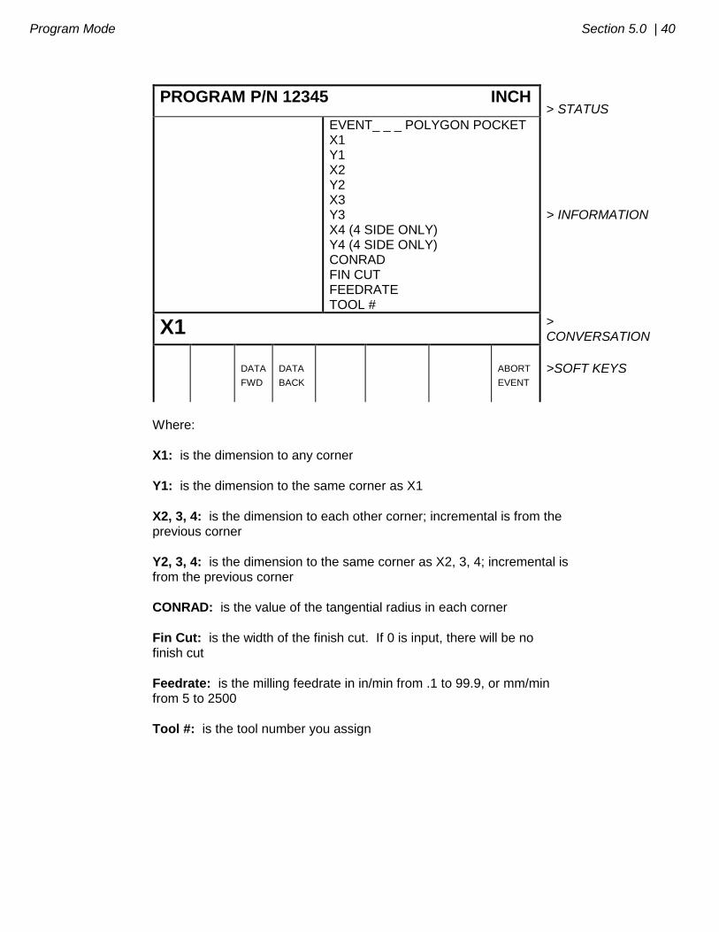
5.11.3 3-Sided or 4-Sided Polygon
Press the 3 SIDE POLY or 4 SIDE POLY soft key if you wish to mill a 3 or 4 sided polygon pocket. Note: The 4-sided polygon pocket may not have an interior angle between adjacent
sides that is greater than 180 degrees. The screen will show:
Program Mode Section 5.0 | 40
PROGRAM P/N 12345 INCH > STATUS
EVENT_ _ _ POLYGON POCKET X1 Y1 X2 Y2 X3 Y3 X4 (4 SIDE ONLY) Y4 (4 SIDE ONLY) CONRAD FIN CUT FEEDRATE TOOL #
> INFORMATION
X1 > CONVERSATION
DATA
FWD
DATA
BACK
ABORT
EVENT
>SOFT KEYS
Where:
X1: is the dimension to any corner
Y1: is the dimension to the same corner as X1
X2, 3, 4: is the dimension to each other corner; incremental is from the previous corner
Y2, 3, 4: is the dimension to the same corner as X2, 3, 4; incremental is from the previous corner
CONRAD: is the value of the tangential radius in each corner
Fin Cut: is the width of the finish cut. If 0 is input, there will be no finish cut
Feedrate: is the milling feedrate in in/min from .1 to 99.9, or mm/min from 5 to 2500
Tool #: is the tool number you assign

41 | Section 5.0 Program Mode
5.11.4 Irregular Pocket Press the IRREGULAR soft key if you wish to mill an irregular shaped pocket made up of straight lines (Mills) and arcs. The first screen in an irregular pocket defines some of its general parameters. The screen will show:
PROGRAM P/N 12345 INCH > STATUS
EVENT_ _ _ IRREG TOOL OFFSET FEEDRATE FIN CUT FIN FEEDRATE TOOL #
> INFORMATION
TOOL OFFSET, 0=CENTER, 1=RIGHT, 2=LEFT > CONVERSATION
DATA
FWD
DATA
BACK
ABORT
EVENT
>SOFT KEYS
Where:
Tool Offset: is the selection of the tool offset to the right (input 1) or offset to the left (input 2) in the programmed direction around the pocket perimeter. Do
not select 0 for tool center. In other words, input 1 if programming clockwise around the perimeter, or input 2 if counterclockwise.
Feedrate: is the milling feedrate in in/min from .1 to 99.9, or mm/min from 5 to 2500
Fin Cut: is the width of the finish cut. If 0 is input, there will be no finish cut
Fin Feedrate: is the finish cut milling feedrate in in/min from .1 to 99.9, or mm/min from 5 to 2500.
Tool #: is the tool number you assign When the above screen is complete, you need to define the shape of the pocket using Mill and ARC events with (or without) Conrads. The TRAK A.G.E. 2 will prompt for each event (or side of the pocket) in the same way as mill and arc events with YES continues. When the last side is programmed,
press the END CONTIN soft key. There are a few rules which must be followed to program a legitimate pocket. 1. The pocket may have no more than 20 sides. 2. The last side (or event) must end where the first side (or event) began.
Program Mode Section 5.0 | 42
3. No "islands" may exist in the pocket. 4. The pocket is cleared by zig zag machining along the X axis starting at the most negative Y position. Consequently, there must not be "hidden" sections when machining along X. Note: If your part has hidden sections, program it as two pockets.
In Program Run, the pocket path will be zig-zag cuts along X, followed by a rough cut along the inside of the perimeter, followed by a finish pass (if FIN CUT was not zero) along the inside of the perimeter at the Finish Feedrate.
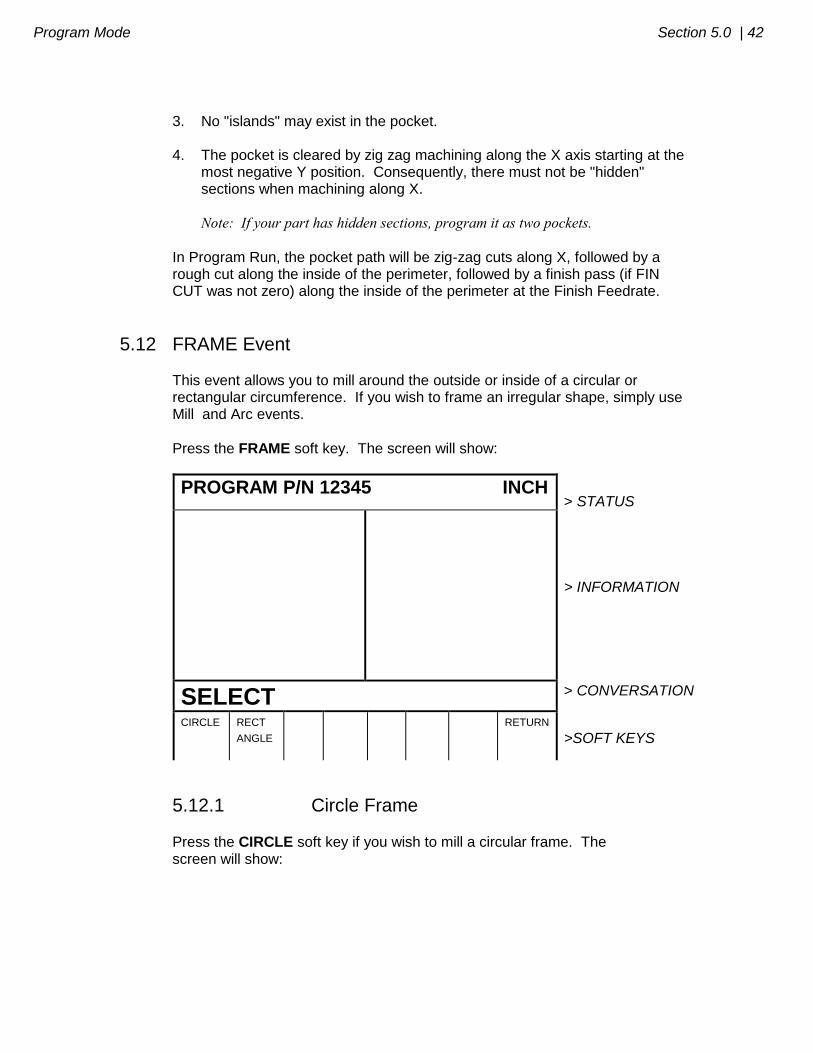
5.12 FRAME Event This event allows you to mill around the outside or inside of a circular or rectangular circumference. If you wish to frame an irregular shape, simply use Mill and Arc events.
Press the FRAME soft key. The screen will show:
PROGRAM P/N 12345 INCH > STATUS
> INFORMATION
SELECT > CONVERSATION
CIRCLE
RECT
ANGLE
RETURN
>SOFT KEYS
5.12.1 Circle Frame
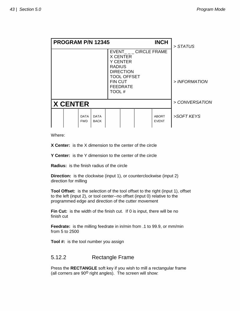
Press the CIRCLE soft key if you wish to mill a circular frame. The screen will show:
43 | Section 5.0 Program Mode
PROGRAM P/N 12345 INCH > STATUS
EVENT_ _ _ CIRCLE FRAME X CENTER Y CENTER RADIUS DIRECTION TOOL OFFSET FIN CUT FEEDRATE TOOL #
> INFORMATION
X CENTER > CONVERSATION
DATA
FWD
DATA
BACK
ABORT
EVENT
>SOFT KEYS
Where:
X Center: is the X dimension to the center of the circle
Y Center: is the Y dimension to the center of the circle
Radius: is the finish radius of the circle
Direction: is the clockwise (input 1), or counterclockwise (input 2) direction for milling
Tool Offset: is the selection of the tool offset to the right (input 1), offset to the left (input 2), or tool center--no offset (input 0) relative to the programmed edge and direction of the cutter movement
Fin Cut: is the width of the finish cut. If 0 is input, there will be no finish cut
Feedrate: is the milling feedrate in in/min from .1 to 99.9, or mm/min from 5 to 2500
Tool #: is the tool number you assign
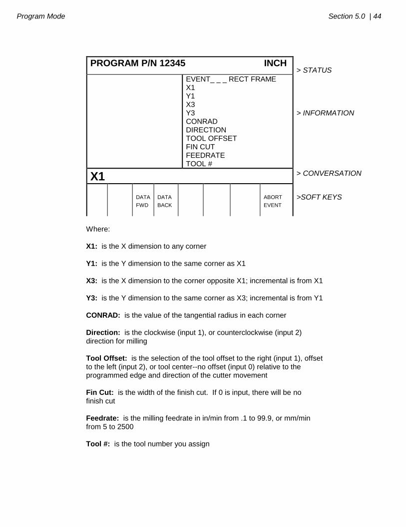
5.12.2 Rectangle Frame
Press the RECTANGLE soft key if you wish to mill a rectangular frame (all corners are 90o right angles). The screen will show:
Program Mode Section 5.0 | 44
PROGRAM P/N 12345 INCH > STATUS
EVENT_ _ _ RECT FRAME X1 Y1 X3 Y3 CONRAD DIRECTION TOOL OFFSET FIN CUT FEEDRATE TOOL #
> INFORMATION
X1 > CONVERSATION
DATA
FWD
DATA
BACK
ABORT
EVENT
>SOFT KEYS
Where:
X1: is the X dimension to any corner
Y1: is the Y dimension to the same corner as X1
X3: is the X dimension to the corner opposite X1; incremental is from X1
Y3: is the Y dimension to the same corner as X3; incremental is from Y1
CONRAD: is the value of the tangential radius in each corner
Direction: is the clockwise (input 1), or counterclockwise (input 2) direction for milling
Tool Offset: is the selection of the tool offset to the right (input 1), offset to the left (input 2), or tool center--no offset (input 0) relative to the programmed edge and direction of the cutter movement
Fin Cut: is the width of the finish cut. If 0 is input, there will be no finish cut
Feedrate: is the milling feedrate in in/min from .1 to 99.9, or mm/min from 5 to 2500
Tool #: is the tool number you assign
45 | Section 5.0 Program Mode
5.13 Subroutine Events The Subroutine Event is divided into three options: Repeat, Mirror, and Rotate.
REPEAT allows you to repeat an event or a group of events up to 99 times with an offset in X and/or Y. This can be useful for drilling a series of evenly spaced holes, duplicating some machined shapes, or even repeating an entire program with an offset for a second fixture. Another use is to repeat a programmed set of drill events (without offset) so you can center drill, drill, and counterbore without reprogramming the second and third procedures. Repeat events may be "nested" five deep. That is, you can repeat a repeat event, of a repeat event, of a repeat event of some programmed event(s). One new tool number may be assigned for each Repeat Event.
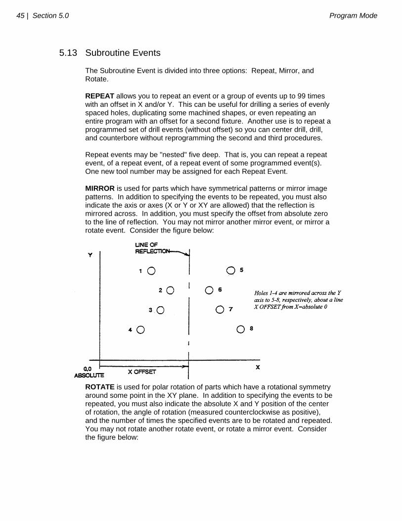
MIRROR is used for parts which have symmetrical patterns or mirror image patterns. In addition to specifying the events to be repeated, you must also indicate the axis or axes (X or Y or XY are allowed) that the reflection is mirrored across. In addition, you must specify the offset from absolute zero to the line of reflection. You may not mirror another mirror event, or mirror a rotate event. Consider the figure below:
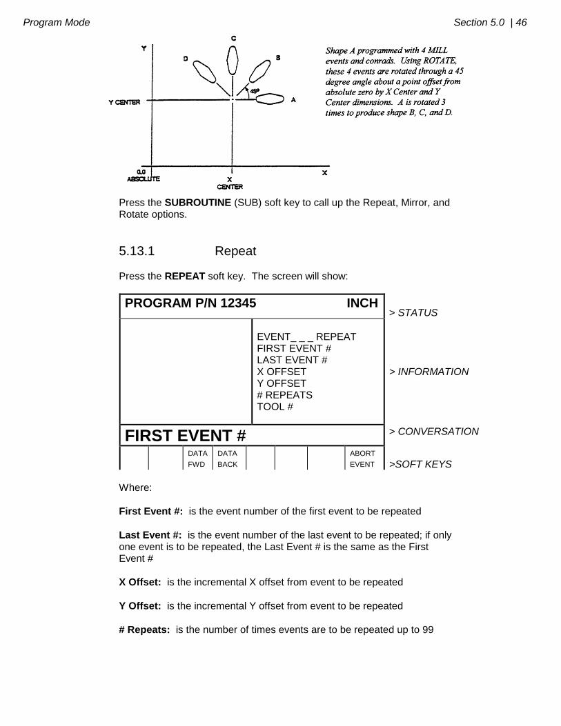
ROTATE is used for polar rotation of parts which have a rotational symmetry around some point in the XY plane. In addition to specifying the events to be repeated, you must also indicate the absolute X and Y position of the center of rotation, the angle of rotation (measured counterclockwise as positive), and the number of times the specified events are to be rotated and repeated. You may not rotate another rotate event, or rotate a mirror event. Consider the figure below:
Program Mode Section 5.0 | 46
Press the SUBROUTINE (SUB) soft key to call up the Repeat, Mirror, and Rotate options.
5.13.1 Repeat
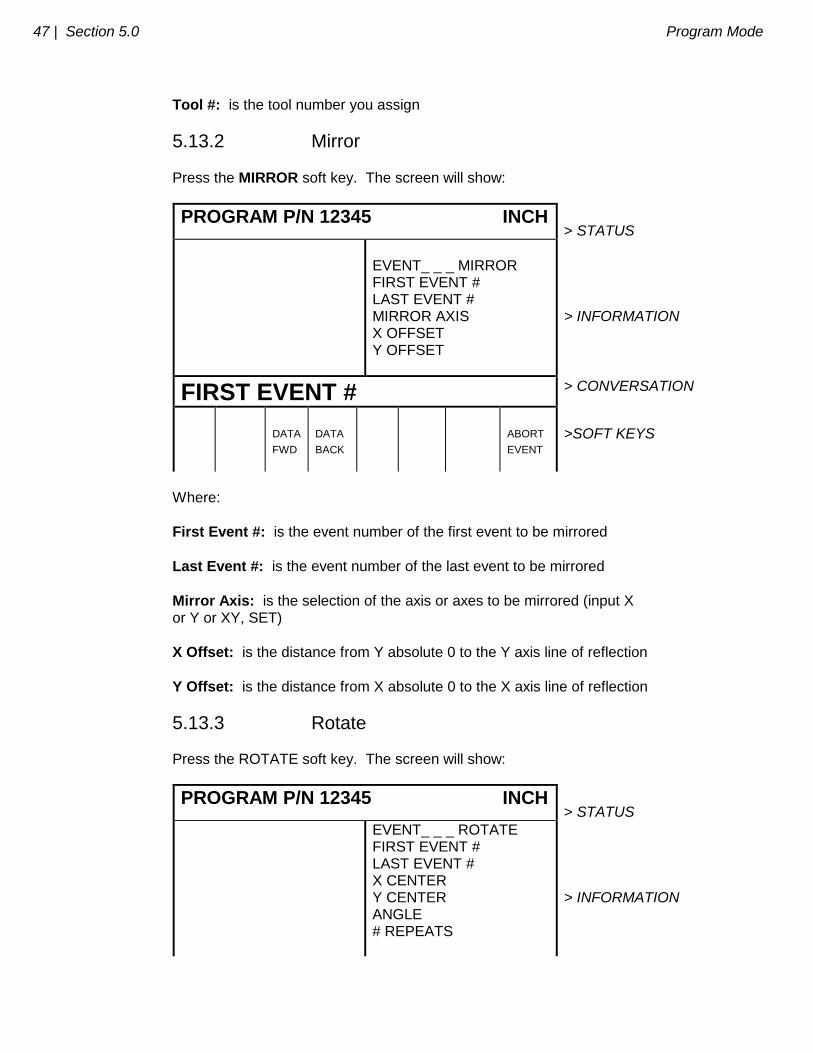
Press the REPEAT soft key. The screen will show:
PROGRAM P/N 12345 INCH > STATUS
EVENT_ _ _ REPEAT FIRST EVENT # LAST EVENT # X OFFSET Y OFFSET # REPEATS TOOL #
> INFORMATION
FIRST EVENT # > CONVERSATION
DATA
FWD
DATA
BACK
ABORT
EVENT
>SOFT KEYS
Where:
First Event #: is the event number of the first event to be repeated
Last Event #: is the event number of the last event to be repeated; if only one event is to be repeated, the Last Event # is the same as the First Event #
X Offset: is the incremental X offset from event to be repeated
Y Offset: is the incremental Y offset from event to be repeated
# Repeats: is the number of times events are to be repeated up to 99
47 | Section 5.0 Program Mode
Tool #: is the tool number you assign
5.13.2 Mirror
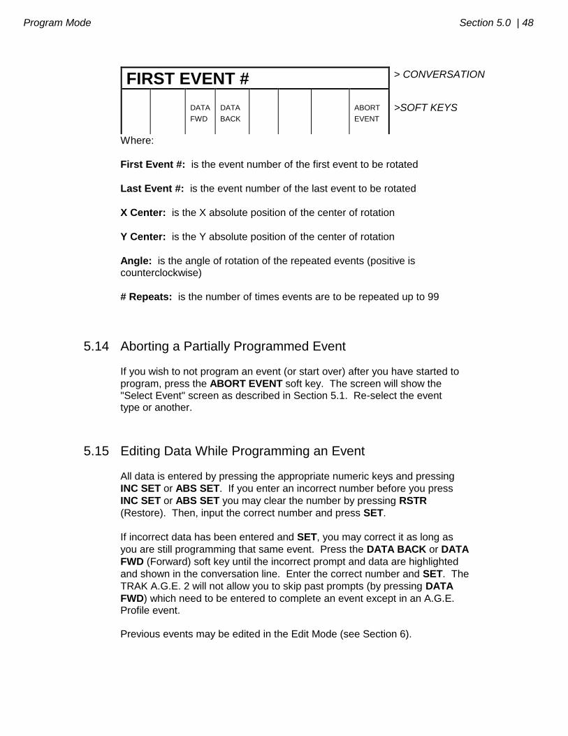
Press the MIRROR soft key. The screen will show:
PROGRAM P/N 12345 INCH > STATUS
EVENT_ _ _ MIRROR FIRST EVENT # LAST EVENT # MIRROR AXIS X OFFSET Y OFFSET
> INFORMATION
FIRST EVENT # > CONVERSATION
DATA
FWD
DATA
BACK
ABORT
EVENT
>SOFT KEYS
Where:
First Event #: is the event number of the first event to be mirrored
Last Event #: is the event number of the last event to be mirrored
Mirror Axis: is the selection of the axis or axes to be mirrored (input X or Y or XY, SET)
X Offset: is the distance from Y absolute 0 to the Y axis line of reflection
Y Offset: is the distance from X absolute 0 to the X axis line of reflection
5.13.3 Rotate Press the ROTATE soft key. The screen will show:
PROGRAM P/N 12345 INCH > STATUS
EVENT_ _ _ ROTATE FIRST EVENT # LAST EVENT # X CENTER Y CENTER ANGLE # REPEATS
> INFORMATION
Program Mode Section 5.0 | 48
FIRST EVENT # > CONVERSATION
DATA
FWD
DATA
BACK
ABORT
EVENT
>SOFT KEYS
Where:
First Event #: is the event number of the first event to be rotated
Last Event #: is the event number of the last event to be rotated
X Center: is the X absolute position of the center of rotation
Y Center: is the Y absolute position of the center of rotation
Angle: is the angle of rotation of the repeated events (positive is counterclockwise)
# Repeats: is the number of times events are to be repeated up to 99
5.14 Aborting a Partially Programmed Event If you wish to not program an event (or start over) after you have started to
program, press the ABORT EVENT soft key. The screen will show the "Select Event" screen as described in Section 5.1. Re-select the event type or another.
5.15 Editing Data While Programming an Event All data is entered by pressing the appropriate numeric keys and pressing
INC SET or ABS SET. If you enter an incorrect number before you press
INC SET or ABS SET you may clear the number by pressing RSTR
(Restore). Then, input the correct number and press SET.
If incorrect data has been entered and SET, you may correct it as long as
you are still programming that same event. Press the DATA BACK or DATA
FWD (Forward) soft key until the incorrect prompt and data are highlighted
and shown in the conversation line. Enter the correct number and SET. The
TRAK A.G.E. 2 will not allow you to skip past prompts (by pressing DATA
FWD) which need to be entered to complete an event except in an A.G.E. Profile event. Previous events may be edited in the Edit Mode (see Section 6).
49 | Section 5.0 Program Mode
5.16 LOOK As you program each event, it may be helpful to see what you have done graphically displayed on the screen. For quick graphics while in the Program
Mode, press the LOOK key located in the upper right area of the keyboard. This function is active at the end of each event, or whenever the conversation
line is prompting Select Event. Press the LOOK key and the TRAK A.G.E. 2 will draw the part in the information area. Note that it will first quickly cycle
through the program to properly size the part to fit the screen. Press RETURN to bring back the Select Event screen. You may also zoom in and shift the screen for a better view of a detail. See Section 7.3 for instructions for the zoom and shift soft keys. Note: The LOOK routine does not check for programming errors. Use DrawPart or
Tool Path (Section 7.3) to check the program.
5.17 Finish Cuts The Pocket and Frame events are designed with built-in finish cut routines because they are complete, and stand-alone pieces of geometry. Shapes machined with a series of Mill or Arc events (either with or without Continue Mill) don't have an automatic routine for making finish cuts. There is, however, a very simple technique which can be used. a. Program the shape using the print dimensions, and ignore the need to leave material for a finish cut. b. Using a subroutine event, Repeat all the events in "a." but call out a different tool number. c. In Set-Up Mode "lie" about the tool diameter for the tool called out in events in "a.". Input a tool diameter equal to the actual tool diameter plus 2 times the finish cut you wish to leave. The TRAK A.G.E. 2 will think the tool is bigger than it really is and, therefore, shift a little further away from the machined shape. d. In Set-Up Mode input the actual diameter for the tool called in the Repeat event "b.". This will produce the final dimensioned cut.
5.18 Do One Events The major portion of some jobs can best be done manually with DRO. However, there are often just a few cuts that require excessive time or complicated set-up, for example, arcs or diagonals. DO ONE programming assists you in performing these more difficult operations without the necessity of complete programs.
Program Mode Section 5.0 | 50
DO ONE events may only be programmed and run one at a time. When a DO ONE event has been run, it is erased from the TRAK A.G.E. 2 memory. The incremental reference position for any DO ONE event is the current position of the tool (or actually the table and saddle). That is, the position at the time the event is run. So an incremental input will move the table by that amount from where it currently is. The absolute reference is unchanged. DO ONE programming is nearly identical to the complete part programming described in Section 5, with these differences:
a. Press the DO ONE soft key in the DRO Mode to activate this routine. b. You do not have to program a tool number. Since the program has only one event, you need only one tool. c. You will be prompted for tool diameter during DO ONE programming. Therefore, you do not need to enter SET UP Mode. d. DO ONE Mill and Arc Events will not prompt for CONRAD. There is no second event to connect to. e. There cannot be a DO ONE A.G.E. Profile event. f. There cannot be a DO ONE Subroutine event. g. You cannot draw a DO ONE part or tool path in Set-Up Mode, or with the LOOK key (see 5.16).
When the DO ONE event is complete, press START to run DO ONE.
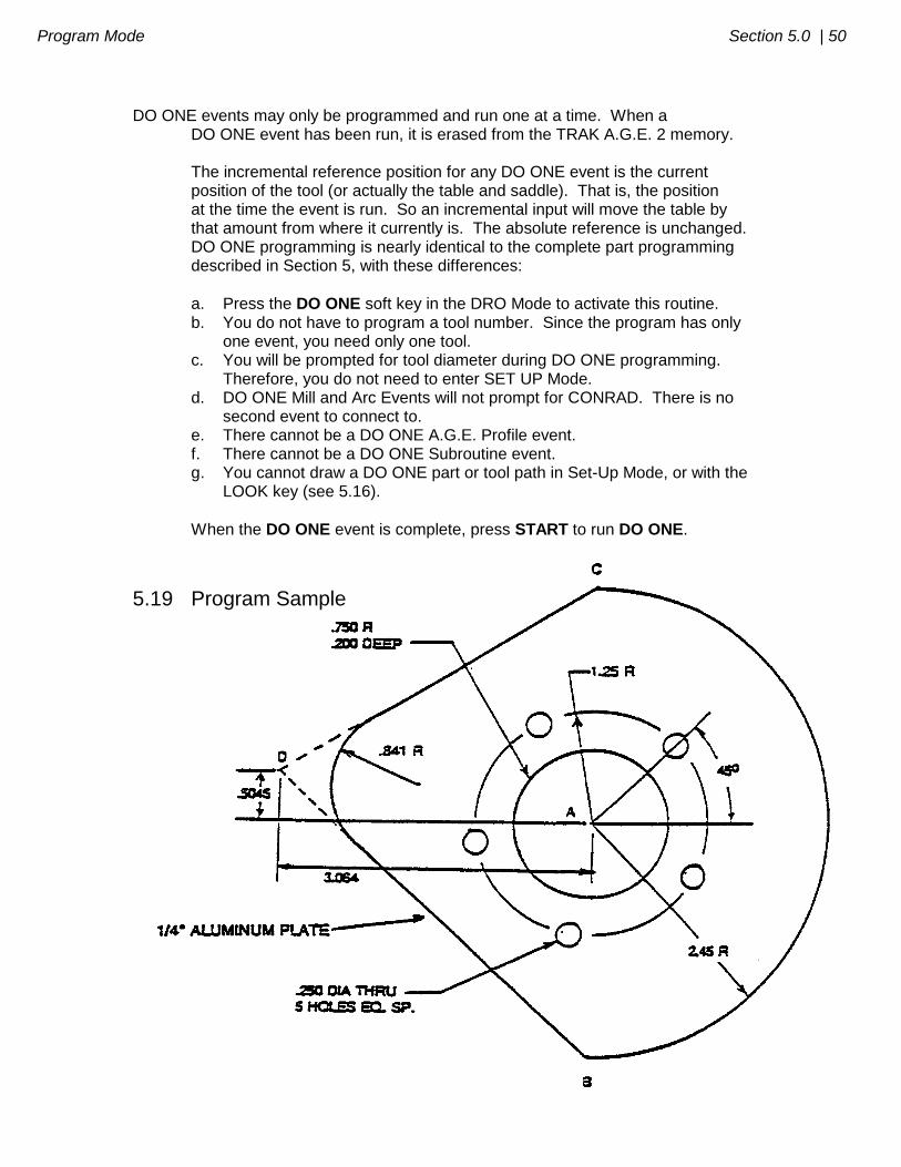
5.19 Program Sample
51 | Section 5.0 Program Mode
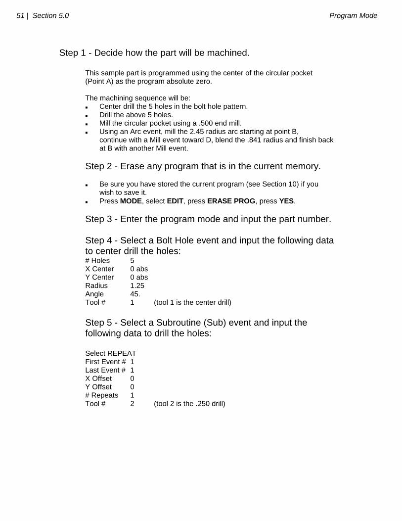
Step 1 - Decide how the part will be machined. This sample part is programmed using the center of the circular pocket (Point A) as the program absolute zero. The machining sequence will be: Center drill the 5 holes in the bolt hole pattern. Drill the above 5 holes. Mill the circular pocket using a .500 end mill. Using an Arc event, mill the 2.45 radius arc starting at point B, continue with a Mill event toward D, blend the .841 radius and finish back at B with another Mill event.
Step 2 - Erase any program that is in the current memory. Be sure you have stored the current program (see Section 10) if you wish to save it.
Press MODE, select EDIT, press ERASE PROG, press YES.
Step 3 - Enter the program mode and input the part number. Step 4 - Select a Bolt Hole event and input the following data to center drill the holes: # Holes 5 X Center 0 abs Y Center 0 abs Radius 1.25 Angle 45. Tool # 1 (tool 1 is the center drill)
Step 5 - Select a Subroutine (Sub) event and input the following data to drill the holes: Select REPEAT First Event # 1 Last Event # 1 X Offset 0 Y Offset 0 # Repeats 1 Tool # 2 (tool 2 is the .250 drill)
Program Mode Section 5.0 | 52
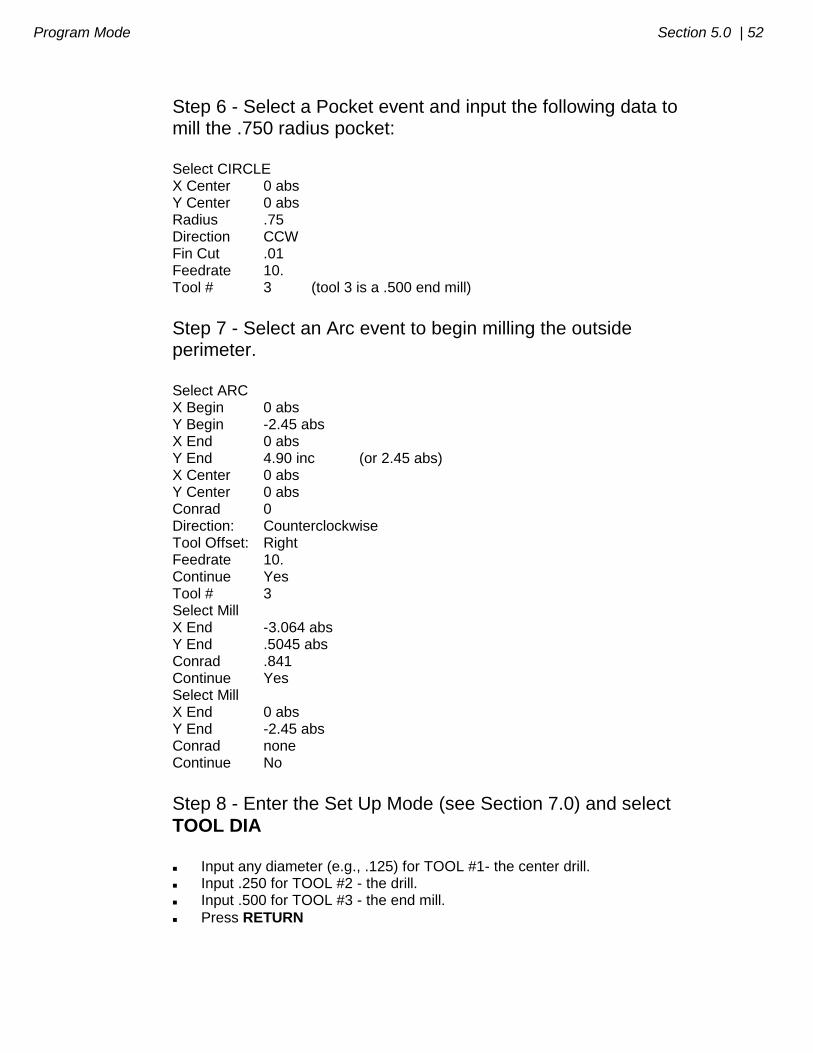
Step 6 - Select a Pocket event and input the following data to mill the .750 radius pocket: Select CIRCLE X Center 0 abs Y Center 0 abs Radius .75 Direction CCW Fin Cut .01 Feedrate 10. Tool # 3 (tool 3 is a .500 end mill)
Step 7 - Select an Arc event to begin milling the outside perimeter. Select ARC X Begin 0 abs Y Begin -2.45 abs X End 0 abs Y End 4.90 inc (or 2.45 abs) X Center 0 abs Y Center 0 abs Conrad 0 Direction: Counterclockwise Tool Offset: Right Feedrate 10. Continue Yes Tool # 3 Select Mill X End -3.064 abs Y End .5045 abs Conrad .841 Continue Yes Select Mill X End 0 abs Y End -2.45 abs Conrad none Continue No
Step 8 - Enter the Set Up Mode (see Section 7.0) and select
TOOL DIA Input any diameter (e.g., .125) for TOOL #1- the center drill. Input .250 for TOOL #2 - the drill. Input .500 for TOOL #3 - the end mill.
Press RETURN
53 | Section 5.0 Program Mode
Step 9 - Check your program by selecting DRAW PART and
pressing START
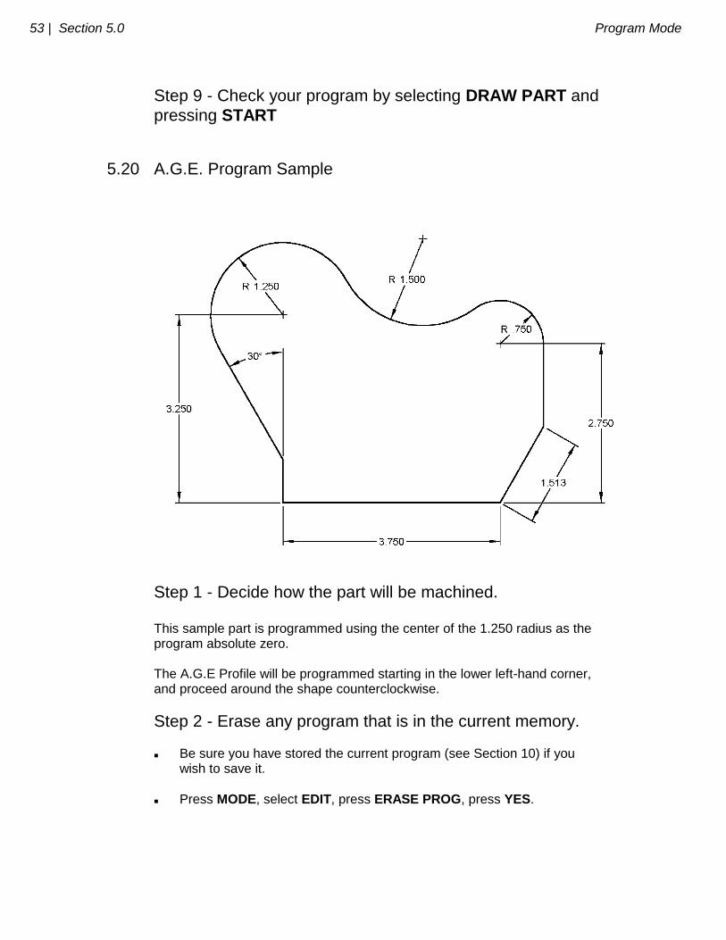
5.20 A.G.E. Program Sample
Step 1 - Decide how the part will be machined. This sample part is programmed using the center of the 1.250 radius as the program absolute zero. The A.G.E Profile will be programmed starting in the lower left-hand corner, and proceed around the shape counterclockwise.
Step 2 - Erase any program that is in the current memory. Be sure you have stored the current program (see Section 10) if you wish to save it.
Press MODE, select EDIT, press ERASE PROG, press YES.
Program Mode Section 5.0 | 54
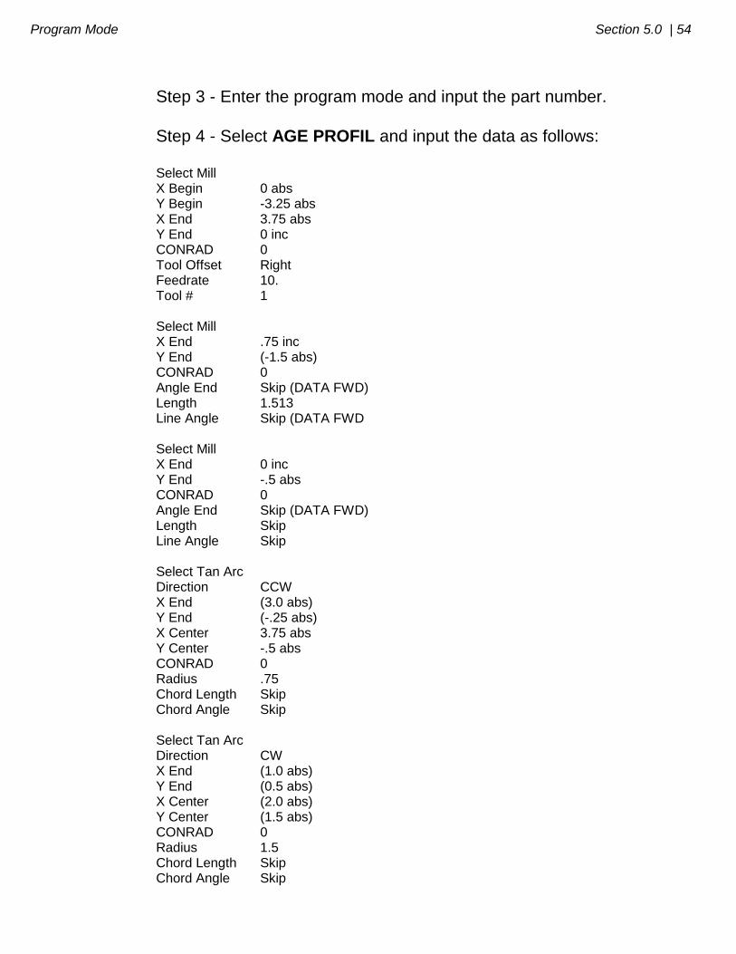
Step 3 - Enter the program mode and input the part number.
Step 4 - Select AGE PROFIL and input the data as follows: Select Mill X Begin 0 abs Y Begin -3.25 abs X End 3.75 abs Y End 0 inc CONRAD 0 Tool Offset Right Feedrate 10. Tool # 1 Select Mill X End .75 inc Y End (-1.5 abs) CONRAD 0 Angle End Skip (DATA FWD) Length 1.513 Line Angle Skip (DATA FWD Select Mill X End 0 inc Y End -.5 abs CONRAD 0 Angle End Skip (DATA FWD) Length Skip Line Angle Skip Select Tan Arc Direction CCW X End (3.0 abs) Y End (-.25 abs) X Center 3.75 abs Y Center -.5 abs CONRAD 0 Radius .75 Chord Length Skip Chord Angle Skip Select Tan Arc Direction CW X End (1.0 abs) Y End (0.5 abs) X Center (2.0 abs) Y Center (1.5 abs) CONRAD 0 Radius 1.5 Chord Length Skip Chord Angle Skip
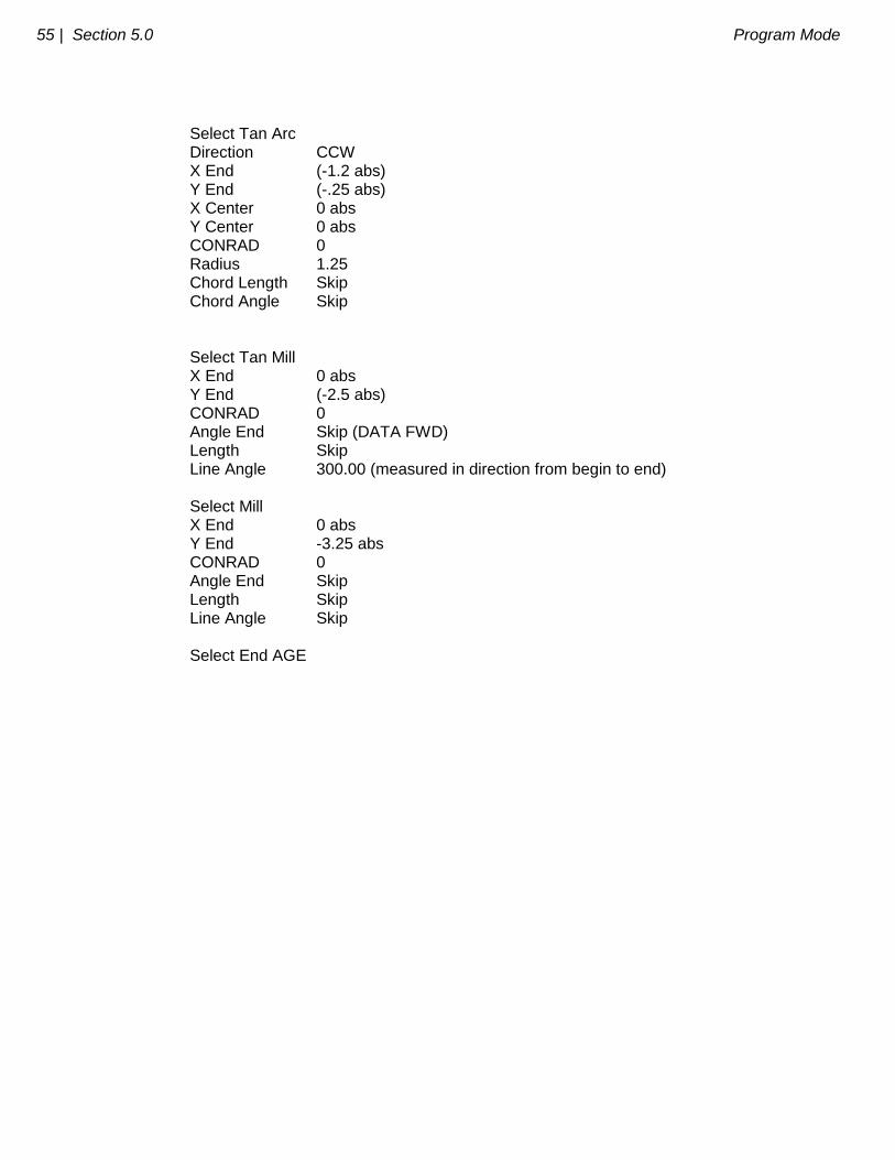
55 | Section 5.0 Program Mode
Select Tan Arc Direction CCW X End (-1.2 abs) Y End (-.25 abs) X Center 0 abs Y Center 0 abs CONRAD 0 Radius 1.25 Chord Length Skip Chord Angle Skip Select Tan Mill X End 0 abs Y End (-2.5 abs) CONRAD 0 Angle End Skip (DATA FWD) Length Skip Line Angle 300.00 (measured in direction from begin to end) Select Mill X End 0 abs Y End -3.25 abs CONRAD 0 Angle End Skip Length Skip Line Angle Skip Select End AGE
_________________________________________________________________ Southwestern Industries, Inc.
TRAK A.G.E. 2 Programming, Operating & Care Manual
SECTION
____________ 6.0 _____________________________
Edit Mode
Edit Mode Section 6.0 | 57
6.0 EDIT MODE The TRAK A.G.E. 2 allows for complete editing of programs including recall (and correction) of data, adding events in the middle of a program, deleting events within the program, and erasing programs.
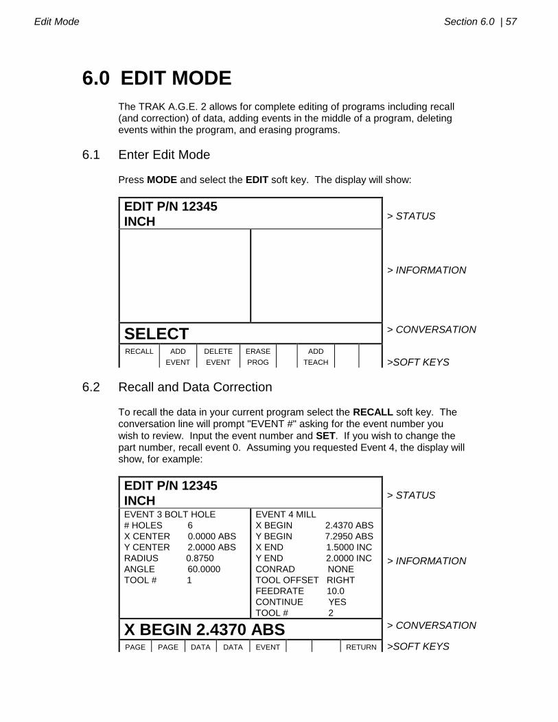
6.1 Enter Edit Mode
Press MODE and select the EDIT soft key. The display will show:
EDIT P/N 12345
INCH
> STATUS
> INFORMATION
SELECT > CONVERSATION
RECALL
ADD
EVENT
DELETE
EVENT
ERASE
PROG
ADD
TEACH
>SOFT KEYS
6.2 Recall and Data Correction
To recall the data in your current program select the RECALL soft key. The conversation line will prompt "EVENT #" asking for the event number you
wish to review. Input the event number and SET. If you wish to change the part number, recall event 0. Assuming you requested Event 4, the display will show, for example:
EDIT P/N 12345
INCH
> STATUS
EVENT 3 BOLT HOLE
# HOLES 6
X CENTER 0.0000 ABS
Y CENTER 2.0000 ABS
RADIUS 0.8750
ANGLE 60.0000
TOOL # 1
EVENT 4 MILL
X BEGIN 2.4370 ABS
Y BEGIN 7.2950 ABS
X END 1.5000 INC
Y END 2.0000 INC
CONRAD NONE
TOOL OFFSET RIGHT
FEEDRATE 10.0
CONTINUE YES
TOOL # 2
> INFORMATION
X BEGIN 2.4370 ABS > CONVERSATION
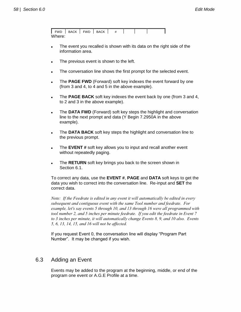
PAGE PAGE DATA DATA EVENT RETURN >SOFT KEYS
58 | Section 6.0 Edit Mode
FWD BACK FWD BACK #
Where: The event you recalled is shown with its data on the right side of the information area. The previous event is shown to the left. The conversation line shows the first prompt for the selected event.
The PAGE FWD (Forward) soft key indexes the event forward by one (from 3 and 4, to 4 and 5 in the above example).
The PAGE BACK soft key indexes the event back by one (from 3 and 4, to 2 and 3 in the above example).
The DATA FWD (Forward) soft key steps the highlight and conversation line to the next prompt and data (Y Begin 7.2950A in the above example).
The DATA BACK soft key steps the highlight and conversation line to the previous prompt.
The EVENT # soft key allows you to input and recall another event without repeatedly paging.
The RETURN soft key brings you back to the screen shown in Section 6.1.
To correct any data, use the EVENT #, PAGE and DATA soft keys to get the
data you wish to correct into the conversation line. Re-input and SET the correct data. Note: If the Feedrate is edited in any event it will automatically be edited in every
subsequent and contiguous event with the same Tool number and feedrate. For
example, let's say events 5 through 10, and 13 through 16 were all programmed with
tool number 2, and 5 inches per minute feedrate. If you edit the feedrate in Event 7
to 3 inches per minute, it will automatically change Events 8, 9, and 10 also. Events
5, 6, 13, 14, 15, and 16 will not be affected.
If you request Event 0, the conversation line will display “Program Part Number”. It may be changed if you wish.
6.3 Adding an Event Events may be added to the program at the beginning, middle, or end of the program one event or A.G.E Profile at a time.
Edit Mode Section 6.0 | 59
To do so, press the ADD EVENT soft key from the screen shown in Section 6.1. The conversation line will state "After Event #." Input the event number
which the event you wish to add will follow and press SET. The screen will ask you to "Select Event," and program as you normally would (as described in Section 5). When an event has been added, all subsequent events will be renumbered accordingly. Appropriate adjustments will automatically be made to Subroutine events.
6.4 Deleting an Event Events may be deleted one at a time or in continuous groups.
To do so, press the DELETE EVENT soft key from the screen shown in Section 6.1. The conversation line will state "Delete From #." Input the
first event number of the group to be deleted, and press SET. The conversation line will then read "Delete to #" asking you to input the last
event number of the group to be deleted, and press SET. If only one event is to be deleted, input its event number for both "Delete From #" and "Delete To #." When an event or group of events have been deleted, all subsequent events will be renumbered to eliminate any number gaps. All event numbers in any Subroutine event will also be renumbered.
6.5 Erasing a Program
You may erase your current program by pressing the ERASE PROG soft key shown in the screen in Section 6.1. However, if you ever wish to reuse this program, you must be certain that it has been saved on the TRAK A.G.E. 2 floppy disk memory, or saved offline (see Section 10).
When you press the ERASE PROG soft key, the conversation line will be highlighted and state "ARE YOU SURE YOU WISH TO ERASE THIS
PROGRAM?". If you are, press the YES soft key. If you are not, press the
NO soft key. The display will return to the Select screen shown in Section 6.1

60 | Section 6.0 Edit Mode
6.6 Adding a Teach Program to an Input Program
A program generated from Teach in DRO Mode may be inserted into a regular program. You must have at least a one event program to add the Teach events. To do so, press the ADD TEACH soft key from the screen shown in Section 6.1. The conversation line will state “After Event #”. Input the event number which the Teach program or events will follow, and press SET. You may edit this data as you would in any other event. All Teach events will be added as normal Position or Mill events with CONRAD=0, Tool Offset=Center, Feedrate as set in Teach, Tool #99 and a Continue=YES between successive Teach Mill events. When the Teach events have been added, all subsequent events will be renumbered accordingly. Appropriate adjustments will automatically be made to Subroutine events.
6.7 Editing A.G.E. Profile Events
In the Program Mode when an A.G.E. Profile set of events are complete, the TRAK A.G.E. 2 converts all of the events into standard Mill and Arc events. All of the data in the expanded format (like lengths of lines, etc.) is lost. If you wish to edit events that were programmed with A.G.E. Profile events, you have two options. You may simply edit them as any other event by changing the Begin, End, or Center points if they are known. If not known, you may use the Math Help routines in Section 9 to calculate them. Or, as a second option, you can use the Delete Events function (see Section 6.4) to erase the incorrect events, and then use Add Event (see Section 6.3) and a new A.G.E. Profile to generate the correct events. Note that if the corrected events are in the middle of the original A.G.E. Profile, you will have to use Recall (see Section 6.2) and change the Continue=YES/NO appropriately at the beginning and end of the inserted A.G.E. Profile events.
66 | Section 7.0 Set Up Mode
SECTION
____________ 7.0 _____________________________
Set Up Mode

Set Up Mode Section 7.0 | 67
7.0 SET UP MODE The Set Up Mode is used to input tool diameter information and to visually check out a program.
7.1 Enter Set Up Mode
Press MODE and select the SET UP soft key. The display will show:
SET-UP P/N 12345
INCH
> STATUS
> INFORMATION
SELECT > CONVERSATION
TOOL
DIA
DRAW
PART
TOOL
PATH
SERV
CODES
> SOFT KEYS
7.2 Inputting Tool Diameters Every program has a corresponding Tool Table which is saved and stored
with the program. To enter tool diameter information, press the TOOL DIA soft key. The display will show:
SET-UP P/N 12345
INCH
> STATUS
TOOL # DIA 1 2 3 4 7 9 10
> INFORMATION
TOOL #1 > CONVERSATION
PAGE
FWD
PAGE
BACK
DATA
FWD
DATA
BACK
RETURN >SOFT KEYS

68 | Section 7.0 Set Up Mode
Where: Each tool number that is in program 12345, as well as its diameter, is shown in the information area. The conversation line shows the tool number for which you may input data. If that tool number already has a diameter, it will be shown in the conversation line and may be changed and SET.
The DATA FWD (Forward) soft key indexes the conversation to the next tool number.
The DATA BACK soft key indexes the conversation back to the previous tool number for edit.
The RETURN soft key brings you back to the Set Up Select screen in Section 7.1.
The PAGE FWD (Forward) soft key indexes the list forward if it is too long for one screen.
The PAGE BACK soft key indexes the list back if it is too long for one screen.
7.3 Draw Part Graphics The TRAK A.G.E. 2 allows you to draw the part represented by your current
program. To do so, press the DRAW PART soft key from the screen shown in Section 7.1. The display will show:
SET-UP P/N 12345
INCH
> STATUS
> INFORMATION
> CONVERSATION
START SINGLE
STEP
ZOOM
PLUS
RETURN
> SOFT KEYS
Set Up Mode Section 7.0 | 69
Where:
START: will draw the entire part scaled to fit within the screen drawing area. There may be a few seconds delay while the ProtoTRAK computes the proper scale.
SINGLE STEP: will draw one event at a time scaled to fit within the screen drawing area. The status line will show the event #.
: will shift the drawing up by 10% for each press.
: will shift the drawing down by 10% for each press
: will shift the drawing to the right by 10% for each press
: will shift the drawing to the left by 10% for each press
ZOOM PLUS: will expand the size of the drawing by 10% for each press.
Press the +/- key, and then the ZOOM MINUS key to shrink the drawing.
Press and hold the START soft key for 3 seconds to set the scale and shift back to the center of the screen.
RETURN: brings the display back to the Set-Up Select screen in Section 7.1 In the drawing all position or drill locations are represented by small X's. All part edges programmed with mill, arc, or A.G.E Profile events are shown as solid lines.
7.4 Tool Path Graphics The TRAK A.G.E. 2 allows you to graphically show the tool path associated with your current program. In all cases the path shown on the screen represents the center of the tool. All movements at a programmed feedrate are shown as a solid line.
To show the tool path, press the TOOL PATH soft key from the screen shown in Section 7.1. The display will show the identical screen as the Draw Part Graphics screen (see Section 7.3). The soft keys also operate the same as for Draw Part Graphics.
7.5 Service Codes These are special codes which may be entered into the TRAK A.G.E. 2 to call up routines used in installation checkout and service.
70 | Section 7.0 Set Up Mode
7.5.1 Sensor Calibration: Code 123 Occasionally it may be necessary to recalibrate the TRAK Sensor encoder
accuracy. To do so, select the SERV CODES soft key from the screen in Section 7.1. The conversation line will prompt "CODE." Input 123 and press SET. The procedure is as follows: a. The conversation line prompts "Select Axis." Press X, or Y, or Z. b. The conversation line prompts "Move to Standard Begin, then SET." Place a dial indicator in the spindle and move the table to touch off one end of a standard or piece of material of known length. Press SET. c. The conversation line prompts "Move to Standard End, then SET." Move the table to touch off the other end of the standard. Press SET. d. The conversation line prompts "Input standard length, then SET." Input the length of the standard and press SET. If a legitimate calibration is computed (actual divided by standard length), the system will automatically abort to the SET UP mode of operation. Repeat the entire procedure for each axis to be calibrated. If the calibration is not legitimate, the display will read "Unreasonable Calibration Factor" This occurs if the displayed readout in the calibration procedure was less than the standard length, or too much (the maximum allowable is 1% more than the standard). Verify the standard, repeat the procedure, and request SWI or distributor service if needed.
7.5.2 Metric Default: Code 66 If you wish to have the TRAK A.G.E. 2 power up in the metric measurement mode use the following procedure:
a. Press the SERV CODES soft key from the screen in Section 7.1. b. Press 66 SET when the conversation line prompts "CODE".
7.5.3 English Default: Code 67 If you wish to have the TRAK A.G.E. 2 power up in the English measurement mode use the following procedure:
a. Press the SERV CODES soft key from the screen in Section 7.1. b. Press 67 SET when the conversation line prompts "CODE".
7.5.4 Preset All Defaults: Code 99 If you wish to have all service defaults reset to those standardized at the factory use the following procedure:

Set Up Mode Section 7.0 | 71
a. Press the SERV CODES soft key from the screen in Section 7.1. b. Press 99 SET when the conversation line prompts "CODE".
7.5.5 Software ID: Code 33 If you wish to check the revision of the software in your TRAK A.G.E. 2 use the following procedure: a. Press the SERV CODES soft key from the screen in Section 7.1. b. Press 33 SET when the conversation line prompts "CODE". The software identification will be shown in the Information area of the screen.
7.5.6 Program Scale Factor Use this Scale Factor Code if you wish the part you are making to be larger or smaller than the dimensions you program. For example, if you program 2.0000" by 3.0000" pocket and input a Scale Factor of 1.03, the pocket will be machined 2.0600" by 3.0900". A .97 Scale Factor would produce a 1.9400" by 2.9100" pocket. The default Scale Factor is 1.0000. This produces no change from the programmed data. To input a new Scale Factor use the following procedure: a. Press the SERV CODES soft key from the screen in Section 7.1. b. Press 14 SET when the conversation line prompts "CODE". c. Input the Scale Factor value (from .1000 to 10.0000) and press INC SET. Note: The X, Y and Z dimension data shown in the DRO or RUN modes will always
be the true table, saddle and quill position
In the RUN mode the status line will show "S/F" whenever the Scale Factor is not set
at 1.0000.
7.5.7 Adjust Following Error
When the TRAK A.G.E. 2 operates at high feedrates it may create small part machining errors as it goes around sharp corners. This exists on all CNC’s and is commonly called a “following error.” The TRAK A.G.E. 2 is factory preset to allow a maximum following error of 0.001 inch. The feedrate will automatically be adjusted around sharp corners so as to not violate this limit.
72 | Section 7.0 Set Up Mode
You may adjust the maximum following error to a value as small as .0001 inch. However, the smaller the value, the slower the feedrate around corners. To input a new Following Error use the following procedure:
a) Press the SERV CODES soft key from the screen in Section 7.1.
b) Press 129 SET when the conversation line prompts “CODE”. c) Follow the instructions on the screen and input the Following Error value
(from .0001 to .0100) and press INC SET.
7.5.8 Irregular Pocket Stepover
In Irregular Pocket run, each machining pass cuts material equal to 71 percent of the tool diameter (this transfers into nearly 100% at certain corners). This represents a maximum cut or stepover. This maximum stepover may be reduced by a factor from 1.0 (no change) to 0.1 (10 percent of the maximum). To input a new factor, use the following procedure:
a) Press the SERV CODES soft key from the screen in Section 7.1.
b) Press 140 SET when the conversation line prompts “CODE”.
c) Input the new stepover factor and press INC SET.
7.5.9 Save Calibration Constants to System Disk
Calibration constants (for sensors, ball screws, etc.) and certain system configuration data are stored in the TRAK A.G.E. 2 computer EEPROM memory chips. This Service Code allows you to copy these parameters to your system disk. The value of this is that if you have a computer module failure, your serviceman can copy the parameters from the disk back into the corrected computer memory without recalibrating the entire machine tool. To save the calibration constants to the system disk, use the following procedure:
a) Press the SERV CODE soft key from the screen in Section 7.1.
b) Press 142 SET when the conversation line prompts “CODE”.
c) Read the instructions and press the YES soft key if you wish to execute the operation.
_________________________________________________________________ Southwestern Industries, Inc.
TRAK A.G.E. 2 Programming, Operating & Care Manual
SECTION
____________ 8.0 _____________________________
Program Run Mode
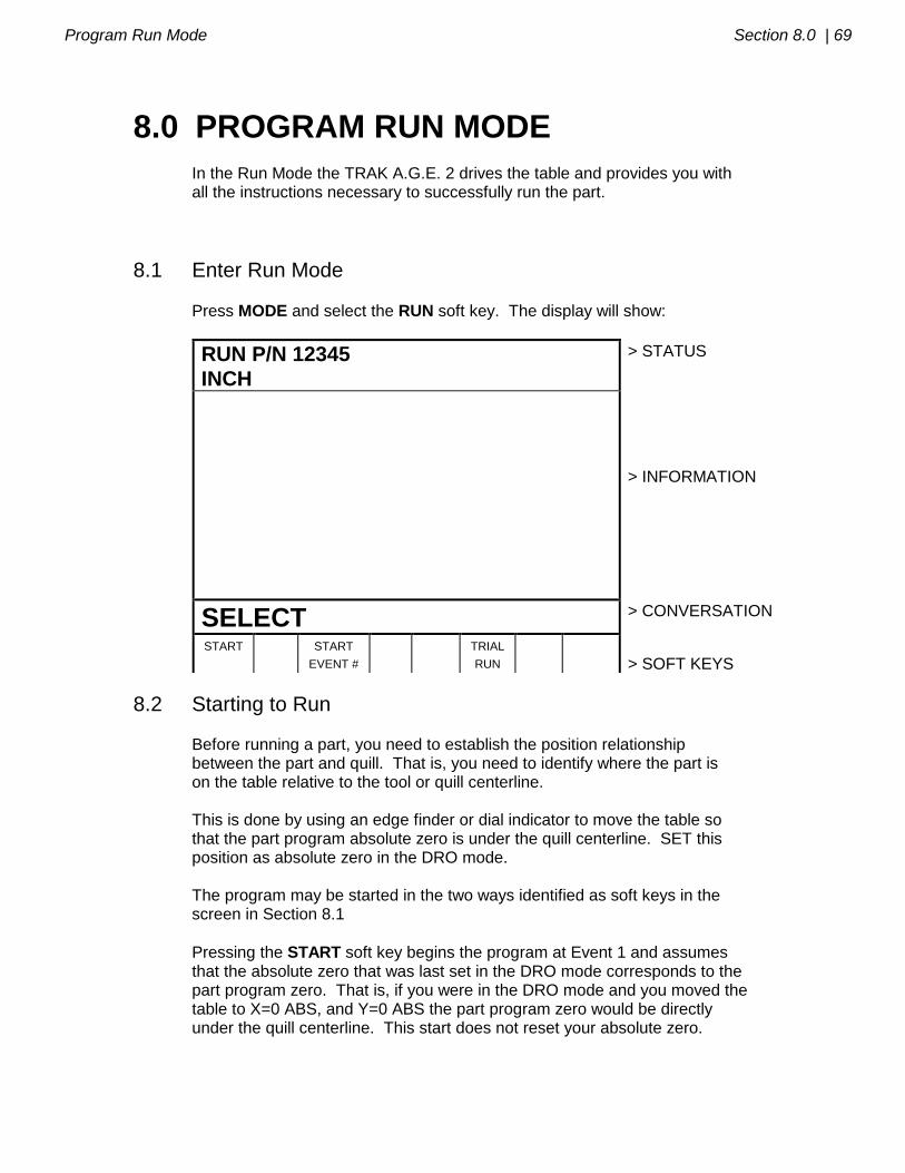
Program Run Mode Section 8.0 | 69
8.0 PROGRAM RUN MODE In the Run Mode the TRAK A.G.E. 2 drives the table and provides you with all the instructions necessary to successfully run the part.
8.1 Enter Run Mode
Press MODE and select the RUN soft key. The display will show:
RUN P/N 12345
INCH
> STATUS
> INFORMATION
SELECT > CONVERSATION
START START
EVENT #
TRIAL
RUN
> SOFT KEYS
8.2 Starting to Run Before running a part, you need to establish the position relationship between the part and quill. That is, you need to identify where the part is on the table relative to the tool or quill centerline. This is done by using an edge finder or dial indicator to move the table so that the part program absolute zero is under the quill centerline. SET this position as absolute zero in the DRO mode. The program may be started in the two ways identified as soft keys in the screen in Section 8.1
Pressing the START soft key begins the program at Event 1 and assumes that the absolute zero that was last set in the DRO mode corresponds to the part program zero. That is, if you were in the DRO mode and you moved the table to X=0 ABS, and Y=0 ABS the part program zero would be directly under the quill centerline. This start does not reset your absolute zero.

70 | Section 8.0 Program Run Mode
Pressing the START EVNT # soft key allows you to start in the middle of a program. This kind of start will not reset the absolute position. When you
press the START EVNT # soft key, the conversation line will prompt "Input Event #." Input the number of the first event you wish to run, and press SET.
8.3 Program Run When you have started by any of the means above, the display will show:
RUN P/N 12345 IN POSITION SERVOS ON INCH > STATUS
EVENT 0 0 1 BOLT HOLE
X 0.0000 ABS
Y 0.0000 ABS
Z 0.0000 ABS
FEEDRATE = 0.0 OVERRIDE = 100%
> INFORMATION
LOAD TOOL 1 DIA: _ _ _ > CONVERSATION
SHOW
ABS
SHOW
INC
SHOW
PATH
SHOW
PROG
> SOFT KEYS
Where: The part number being run is shown in the status line. An "IN POSITION" message will appear in the status line when the program has come to a pause (for example, to drill a hole). A "SERVOS ON" message will appear in the status line when the servo motors are turned on. A "S/F" message will appear in the status line when the Scale Factor is not set at 1.0000 (see Section 7.5.6). The event number and type being run is shown at the top of the information area. The current X, Y, Z absolute positions are shown in the information area. The actual table Feedrate is shown at the bottom of the information area.

Program Run Mode Section 8.0 | 71
The current Feedrate Override % (as controlled by the FEED and
FEED keys) is shown at the bottom of the Information Area. The conversation line will show all appropriate messages (see Section 8.4).
The SHOW ABS soft key (which is automatically assumed if one of the other 3 show keys are not selected) will show the absolute X, Y, Z positions as the part is run.
The SHOW INC soft key will show the incremental (or distance to go within the event) X, Y, Z positions as the part is run.
The SHOW PATH soft key will show the tool path graphics as the part is run (as described in Section 7.4).
The SHOW PROG soft key will show the programmed data for the event being run, and the next event as the part is run. The run procedure is very simple. Follow the instructions on the conversation line and proceed by pressing the GO key.
8.4 Program Run Messages During Program Run, all messages which will help you to run the part will appear in the conversation line. The messages you will usually see are:
Load Tool __ __: Means to load the tool requested and press GO to continue.
Check Z: Means to make sure the quill is properly retracted because the
next move will be rapid. Press GO to continue.
Set Z: Means to drill and retract the quill for a drilling operation, or set and
lock the quill to the proper depth for a milling cut. Press GO to continue.
Run Over: Means that the program run is complete. If you are running a second part which will be fixtured/clamped in the exact same position as the first part, you do not need to relocate the absolute 0 and restart. Instead, press the NEXT PART soft key when the conversation line states
"Run Over" and the system will proceed directly to Event 1 when you press GO.

72 | Section 8.0 Program Run Mode
8.5 Stop
At any time, the program may be halted by pressing the STOP key. This
freezes the program at that point. To continue, press the GO key.
8.6 Feedrate Override
The run feedrate may be changed at any time by pressing the FEED or
FEED keys. Each press changes the programmed feedrate, as well as rapid by 10%.
8.7 Trial Run Trial Run allows you to quickly check out your program before you actually start to make parts. In trial run the table will move at rapid speed regardless of what feedrates are programmed (the rapid speed may be overidden with
FEED and FEED keys). The table will stop at each "stop" location (for example, at each drill location) but immediately continue on without your input.
To do a trial run, press the TRIAL RUN soft key from the screen shown in Section 8.1. The conversation line will read “Check Table and Z, then press GO." Be certain the table is positioned so that if it moves through the part program, it will not reach its travel limit. Also check that the quill is fully
retracted. Press GO to begin.
8.8 Data Errors The Program Mode in Section 5 describes several rules which must be followed to successfully program a part. In addition, a program must make sense geometrically. For example, you can't machine a .250 inch diameter circular pocket using a .500 inch end mill. Data errors will nearly always be detected when the TRAK A.G.E. 2 runs through a program--either as a Trial Run or on an actual part run. They may often be detected in the Set Up mode when using the Draw Part or Tool Path Graphics routines. Whenever the TRAK A.G.E. 2 detects a data error the display will change to a screen typified by the example below.

Program Run Mode Section 8.0 | 73
> STATUS
EXPLANATION
The programmed arc or circle is a point. XY begin, end, center are the same
SOLUTION
Check all XY dimensions
> INFORMATION
Data Error 5013 around event 21 > CONVERSATION
RETURN
> SOFT KEYS
The Conversation Line displays the error number (not necessarily important to you) and the event where the error was detected. This is not necessarily the event which is in error since the system often "looks ahead" to make sure there is compatibility from one event to another. In addition, an explanation is given for each data error type as well as a
suggested solution. Press the RETURN soft key to go back to the Select Mode screen, correct your error, and proceed.
8.9 Fault Messages The TRAK A.G.E. 2 performs a number of automatic checks or self-diagnostics on itself. If problems are found it will signal you through the display. The conversation line will display "Fault __ __ __ __". The information area will display an explanation and suggested solution. Press the RETURN key to get back to the Select Mode screen.
_________________________________________________________________ Southwestern Industries, Inc.
TRAK A.G.E. 2 Programming, Operating & Care Manual
SECTION
____________ 9.0 _____________________________
Math Help Mode

Math Help Mode Section 9.0 | 76
9.0 MATH HELP MODE Prints are, unfortunately, not always drawn and labeled in such a way as to provide all of the points necessary for programming even with the powerful A.G.E. Profile events. To minimize this problem, the TRAK A.G.E. 2 provides a graphic math help function which can be used to automatically calculate points of intersection, centers of arcs, trig functions, square roots, etc.
9.1 Procedure
To enter the Math Help Mode, press MODE and select the MATH HELP soft key. The screen will show:
MATH
INCH
> STATUS
A Line-Line Intersection
B Line-Arc Intersection
C Arc-Arc Intersection
D Line-Arc Tangency
E Centers, Points, Radius, Angles of Circles
F Polar-Cartesian Transformations
G Calculator-Math/Trig
> INFORMATION
SELECT > CONVERSATION
A
B
C
D
E
F
G
TYPE #
> SOFT KEYS
If you already know the math help type you want (see Section 9.3) press the
TYPE # soft key and enter the number and SET. If you do not know the type, select from A through G using the soft keys. If, for example, you wish to find the intersection of a straight line and an arc
or circle, press the B soft key. The screen will show:
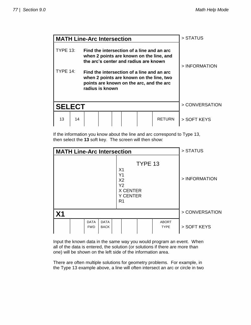
77 | Section 9.0 Math Help Mode
MATH Line-Arc Intersection > STATUS
TYPE 13: TYPE 14:
Find the intersection of a line and an arc
when 2 points are known on the line, and
the arc’s center and radius are known
Find the intersection of a line and an arc
when 2 points are known on the line, two
points are known on the arc, and the arc
radius is known
> INFORMATION
SELECT > CONVERSATION
13
14
RETURN
> SOFT KEYS
If the information you know about the line and arc correspond to Type 13,
then select the 13 soft key. The screen will then show:
MATH Line-Arc Intersection > STATUS
TYPE 13 X1 Y1 X2 Y2 X CENTER Y CENTER R1
> INFORMATION
X1 > CONVERSATION
DATA
FWD
DATA
BACK
ABORT
TYPE
> SOFT KEYS
Input the known data in the same way you would program an event. When all of the data is entered, the solution (or solutions if there are more than one) will be shown on the left side of the information area. There are often multiple solutions for geometry problems. For example, in the Type 13 example above, a line will often intersect an arc or circle in two

Math Help Mode Section 9.0 | 78
places. In these cases all possible solutions will be calculated and displayed. In most cases a careful inspection of the print and some common sense will tell you which solution applies to your problem.
9.2 Calculator-Math and Trig Procedures
If you select soft key G from the first screen in Section 9.1, the display will show:
MATH Calculator-Math/Trig > STATUS
> INFORMATION
> CONVERSATION
+ - x = SQUARE
ROOT
TRIG RETURN
> SOFT KEYS
Use the soft keys like a simple calculator, but always press = for each
calculation. Press RSTR to Clear Entry. For example, for (3 + 9 - 2) 27 4.5
press 3 + 9 = - 2 = x 27 = 4.5 = to get the correct answer = 60
To calculate a square root, press RSTR, the number you wish to find the square root of, and the SQUARE ROOT soft key.
To perform trigonometry functions, press the TRIG soft key. The display will show:
MATH Calculator-Math/Trig INCH > STATUS
> INFORMATION
> CONVERSATION
SINE COS TAN` ARC
SINE
ARC
COS
ARC
TAN
TRI
ANGLE
RETURN
> SOFT KEYS
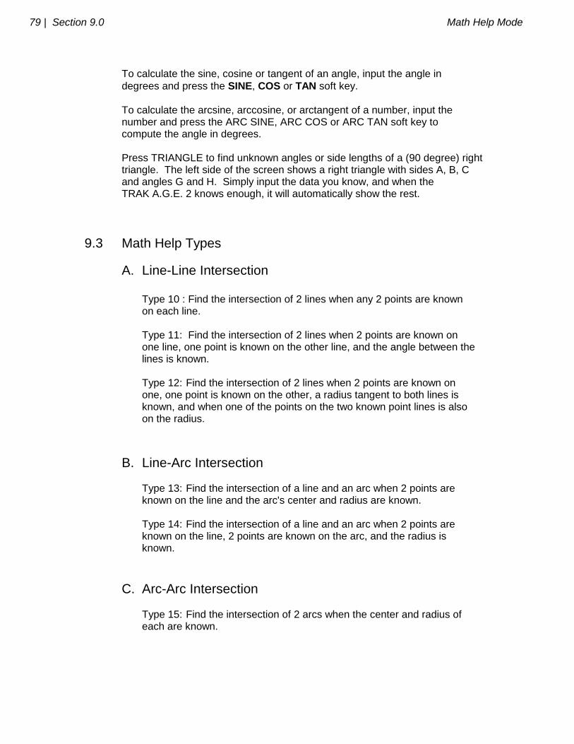
79 | Section 9.0 Math Help Mode
To calculate the sine, cosine or tangent of an angle, input the angle in
degrees and press the SINE, COS or TAN soft key. To calculate the arcsine, arccosine, or arctangent of a number, input the number and press the ARC SINE, ARC COS or ARC TAN soft key to compute the angle in degrees. Press TRIANGLE to find unknown angles or side lengths of a (90 degree) right triangle. The left side of the screen shows a right triangle with sides A, B, C and angles G and H. Simply input the data you know, and when the TRAK A.G.E. 2 knows enough, it will automatically show the rest.
9.3 Math Help Types
A. Line-Line Intersection Type 10 : Find the intersection of 2 lines when any 2 points are known on each line. Type 11: Find the intersection of 2 lines when 2 points are known on one line, one point is known on the other line, and the angle between the lines is known. Type 12: Find the intersection of 2 lines when 2 points are known on one, one point is known on the other, a radius tangent to both lines is known, and when one of the points on the two known point lines is also on the radius.
B. Line-Arc Intersection Type 13: Find the intersection of a line and an arc when 2 points are known on the line and the arc's center and radius are known. Type 14: Find the intersection of a line and an arc when 2 points are known on the line, 2 points are known on the arc, and the radius is known.
C. Arc-Arc Intersection Type 15: Find the intersection of 2 arcs when the center and radius of each are known.
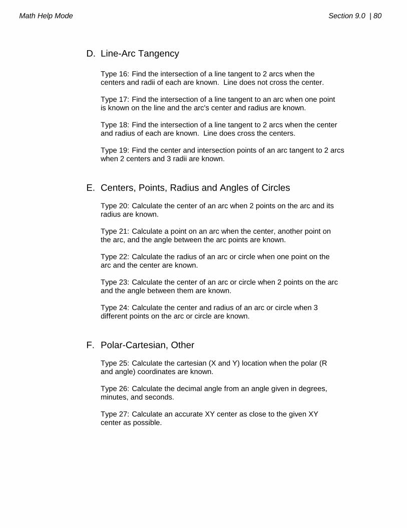
Math Help Mode Section 9.0 | 80
D. Line-Arc Tangency Type 16: Find the intersection of a line tangent to 2 arcs when the centers and radii of each are known. Line does not cross the center. Type 17: Find the intersection of a line tangent to an arc when one point is known on the line and the arc's center and radius are known. Type 18: Find the intersection of a line tangent to 2 arcs when the center and radius of each are known. Line does cross the centers. Type 19: Find the center and intersection points of an arc tangent to 2 arcs when 2 centers and 3 radii are known.
E. Centers, Points, Radius and Angles of Circles Type 20: Calculate the center of an arc when 2 points on the arc and its radius are known. Type 21: Calculate a point on an arc when the center, another point on the arc, and the angle between the arc points are known. Type 22: Calculate the radius of an arc or circle when one point on the arc and the center are known. Type 23: Calculate the center of an arc or circle when 2 points on the arc and the angle between them are known. Type 24: Calculate the center and radius of an arc or circle when 3 different points on the arc or circle are known.
F. Polar-Cartesian, Other Type 25: Calculate the cartesian (X and Y) location when the polar (R and angle) coordinates are known. Type 26: Calculate the decimal angle from an angle given in degrees, minutes, and seconds. Type 27: Calculate an accurate XY center as close to the given XY center as possible.

_________________________________________________________________ Southwestern Industries, Inc.
TRAK A.G.E. 2 Programming, Operating & Care Manual
SECTION
____________ 10.0 ____________________________
Program In/Out Mode
Program In/Out Mode Section 10.0 | 83
10.0 PROGRAM IN/OUT MODE You may store and retrieve programs in two different ways: 1. The TRAK A.G.E. 2 has two built-in floppy disk drives. One holds the system's operating software and is not accessible. The other is accessible through a door in the computer cabinet and can store up to 192 moderate size programs. 2. You may store and retrieve programs through an RS232 link to most computers. The RS232 port is located on the back of the pendant box. This same link is used to load programs which have been written via a CAD/CAM system. All programs are transmitted through the TRAK A.G.E. 2's current or computer program memory. Programs are sent from the computer memory (that is, a current program) to one of the above two permanent memory locations. Or programs are retrieved from one of the two, and loaded into the TRAK A.G.E. 2's computer memory. Programs may not be sent directly from one of the above two storage devices to the other.
10.1 Cautions About Storing and Retrieving Programs Care must be taken to keep from losing a program you wish to keep. This can happen two ways. First, whenever a program is retrieved, it is loaded into the TRAK A.G.E. 2's computer program memory. When this happens, your existing current program is erased. Therefore, if your current program is one you want to keep, be certain to store it before you retrieve another program. Second, to store a program it must have a part number so that the TRAK A.G.E. 2 can find it if you want it retrieved. However, no two programs can have the same part number (how would the system decide which to retrieve?). Therefore, if you store a program with any particular part number, it will automatically erase any other program with that same part number.
10.2 Program Formats And Labeling The TRAK A.G.E. 2 has its own unique programming system--one that organizes the program into events rather than codes and blocks. Most CAD/CAM sytems output their programs in an RS274 format--commonly referred to as a G-code format.
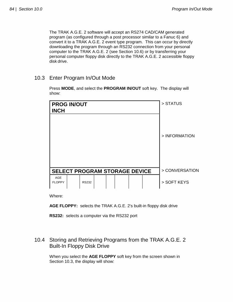
84 | Section 10.0 Program In/Out Mode
The TRAK A.G.E. 2 software will accept an RS274 CAD/CAM generated program (as configured through a post processor similar to a Fanuc 6) and convert it to a TRAK A.G.E. 2 event type program. This can occur by directly downloading the program through an RS232 connection from your personal computer to the TRAK A.G.E. 2 (see Section 10.6) or by transferring your personal computer floppy disk directly to the TRAK A.G.E. 2 accessible floppy disk drive.
10.3 Enter Program In/Out Mode
Press MODE, and select the PROGRAM IN/OUT soft key. The display will show:
PROG IN/OUT
INCH
> STATUS
> INFORMATION
SELECT PROGRAM STORAGE DEVICE > CONVERSATION
AGE
FLOPPY
RS232
> SOFT KEYS
Where:
AGE FLOPPY: selects the TRAK A.G.E. 2's built-in floppy disk drive
RS232: selects a computer via the RS232 port
10.4 Storing and Retrieving Programs from the TRAK A.G.E. 2 Built-In Floppy Disk Drive
When you select the AGE FLOPPY soft key from the screen shown in Section 10.3, the display will show:
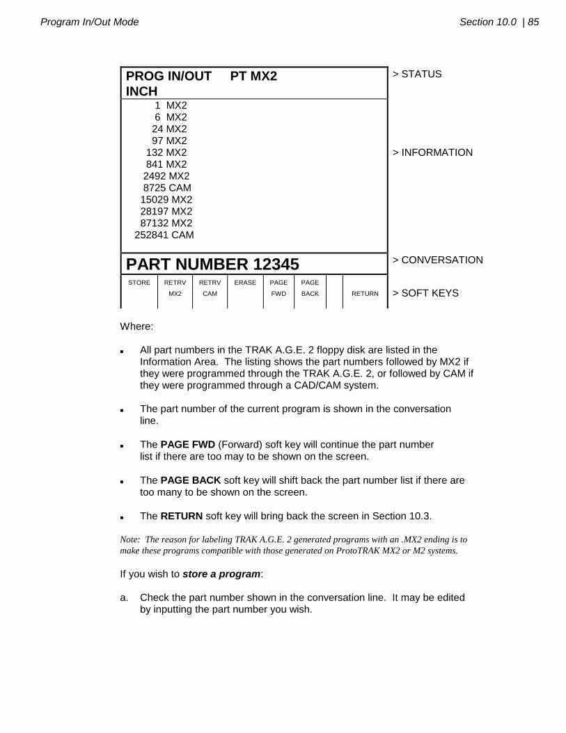
Program In/Out Mode Section 10.0 | 85
PROG IN/OUT PT MX2
INCH
> STATUS
1 MX2 6 MX2 24 MX2 97 MX2 132 MX2 841 MX2 2492 MX2 8725 CAM 15029 MX2 28197 MX2 87132 MX2 252841 CAM
> INFORMATION
PART NUMBER 12345 > CONVERSATION
STORE RETRV
MX2
RETRV
CAM
ERASE PAGE
FWD
PAGE
BACK
RETURN
> SOFT KEYS
Where: All part numbers in the TRAK A.G.E. 2 floppy disk are listed in the Information Area. The listing shows the part numbers followed by MX2 if they were programmed through the TRAK A.G.E. 2, or followed by CAM if they were programmed through a CAD/CAM system. The part number of the current program is shown in the conversation line.
The PAGE FWD (Forward) soft key will continue the part number list if there are too may to be shown on the screen.
The PAGE BACK soft key will shift back the part number list if there are too many to be shown on the screen.
The RETURN soft key will bring back the screen in Section 10.3. Note: The reason for labeling TRAK A.G.E. 2 generated programs with an .MX2 ending is to
make these programs compatible with those generated on ProtoTRAK MX2 or M2 systems.
If you wish to store a program: a. Check the part number shown in the conversation line. It may be edited by inputting the part number you wish.
86 | Section 10.0 Program In/Out Mode
b. Press the STORE soft key. The stored part number will be added to the list.
If you wish to retrieve a program: a. Input the part number so it is shown in the conversation line. Be certain it is a part number in the list.
b. Press the RETRV MX2 soft key if the part is labeled as one generated by the MX2. This program will now be your current program.
c. Press the RETRV CAM soft key if the part is labeled as one generated with a CAM (see Section 10.6). This program will now be your current program.
If you wish to erase a program from the list: a. Input the part number so it is shown in the conversation line. Be certain it is a part number in the list.
b. Press the ERASE soft key. The program will be permanently erased from the floppy disk and the part number will be eliminated from the list.
10.5 Backing Up Your Programs It is strongly recommended that important programs not be solely stored on the TRAK A.G.E. 2 accessible floppy disk drive. A back-up may be made in two ways: a. Remove the accessible floppy diskette which holds the part programs and, using an IBM compatible computer, make a copy or store the data on its hard drive. b. Use the RS232 link (see Section 10.6) to transfer programs to your computer for storage. If at any time you feel the program data on the TRAK A.G.E. 2 floppy diskette is lost or damaged, use your back-up to reproduce the programs.
10.6 Storing and Retrieving Programs through the RS232 Port - Including CAD/CAM Generated Programs
If you wish to use the RS232 port to communicate between your TRAK A.G.E. 2 and your computer, call the Customer Service Group at Southwestern Industries and let us know what computer you wish to interface to. The
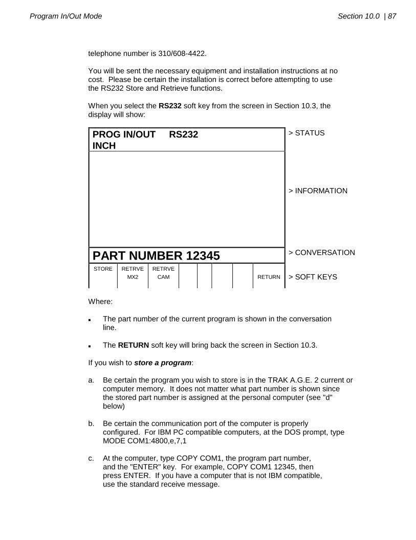
Program In/Out Mode Section 10.0 | 87
telephone number is 310/608-4422. You will be sent the necessary equipment and installation instructions at no cost. Please be certain the installation is correct before attempting to use the RS232 Store and Retrieve functions.
When you select the RS232 soft key from the screen in Section 10.3, the display will show:
PROG IN/OUT RS232
INCH
> STATUS
> INFORMATION
PART NUMBER 12345 > CONVERSATION
STORE RETRVE
MX2
RETRVE
CAM
RETURN
> SOFT KEYS
Where: The part number of the current program is shown in the conversation line.
The RETURN soft key will bring back the screen in Section 10.3.
If you wish to store a program: a. Be certain the program you wish to store is in the TRAK A.G.E. 2 current or computer memory. It does not matter what part number is shown since the stored part number is assigned at the personal computer (see "d" below) b. Be certain the communication port of the computer is properly configured. For IBM PC compatible computers, at the DOS prompt, type MODE COM1:4800,e,7,1 c. At the computer, type COPY COM1, the program part number, and the "ENTER" key. For example, COPY COM1 12345, then press ENTER. If you have a computer that is not IBM compatible, use the standard receive message.
88 | Section 10.0 Program In/Out Mode
d. At the TRAK A.G.E. 2 press the STORE soft key. The program will be written to the floppy disk and the conversation line will read "STORING." When complete, the screen will revert to the one shown in Section 10.3.
If you wish to retrieve a program: a. Input the part number you wish the program to be assigned in the TRAK A.G.E. 2.
b. Press the RETRVE MX2 soft key if the program you wish to retrieve is in the ProtoTRAK MX2, M2 or TRAK A.G.E. 2 event type format. Press the
RETRVE CAM soft key if the program you wish to retrieve is in the CAD/CAM, RS274, G-code format. c. Be certain the communication port at the computer is properly configured. For IBM PC compatible computers, at the DOS prompt, type MODE COM1:4800,e,7,1 Note: If you write a program using a CAD/CAM system on your computer and intend
to enter it into the TRAK A.G.E. 2 via the RS232 port, you must name the program
with one to eight numerical digits followed by a decimal point, followed by CAM (for
example, 123.CAM or 87654321.CAM). If these rules are not followed the TRAK
A.G.E. 2 will not recognize the program.
d. At the computer, type COPY, the program part number, COM1 and the ENTER key. For example, COPY 12345.MX2 COM1, then press ENTER. If you have a computer that is not IBM compatible, use the standard send procedure. e. When the program has been completely received by the TRAK A.G.E. 2, the screen will revert to the one shown in Section 10.3 Note: Do not attempt to write TRAK A.G.E. 2 formatted programs through your
CAD/CAM programming system.
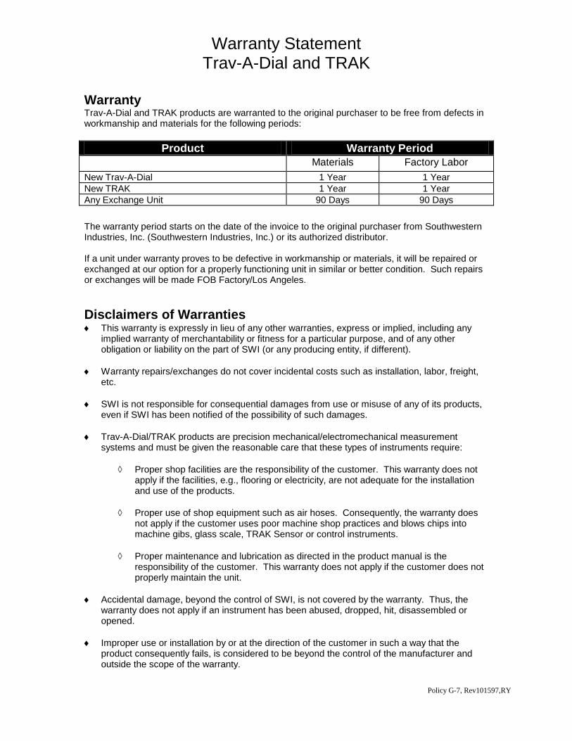
Warranty Statement Trav-A-Dial and TRAK
Warranty Trav-A-Dial and TRAK products are warranted to the original purchaser to be free from defects in workmanship and materials for the following periods:
Product Warranty Period
Materials Factory Labor
New Trav-A-Dial 1 Year 1 Year
New TRAK 1 Year 1 Year
Any Exchange Unit 90 Days 90 Days
The warranty period starts on the date of the invoice to the original purchaser from Southwestern Industries, Inc. (Southwestern Industries, Inc.) or its authorized distributor. If a unit under warranty proves to be defective in workmanship or materials, it will be repaired or exchanged at our option for a properly functioning unit in similar or better condition. Such repairs or exchanges will be made FOB Factory/Los Angeles.
Disclaimers of Warranties This warranty is expressly in lieu of any other warranties, express or implied, including any
implied warranty of merchantability or fitness for a particular purpose, and of any other obligation or liability on the part of SWI (or any producing entity, if different).
Warranty repairs/exchanges do not cover incidental costs such as installation, labor, freight, etc.
SWI is not responsible for consequential damages from use or misuse of any of its products, even if SWI has been notified of the possibility of such damages.
Trav-A-Dial/TRAK products are precision mechanical/electromechanical measurement systems and must be given the reasonable care that these types of instruments require:
Proper shop facilities are the responsibility of the customer. This warranty does not apply if the facilities, e.g., flooring or electricity, are not adequate for the installation and use of the products.
Proper use of shop equipment such as air hoses. Consequently, the warranty does not apply if the customer uses poor machine shop practices and blows chips into machine gibs, glass scale, TRAK Sensor or control instruments.
Proper maintenance and lubrication as directed in the product manual is the responsibility of the customer. This warranty does not apply if the customer does not properly maintain the unit.
Accidental damage, beyond the control of SWI, is not covered by the warranty. Thus, the warranty does not apply if an instrument has been abused, dropped, hit, disassembled or opened.
Improper use or installation by or at the direction of the customer in such a way that the product consequently fails, is considered to be beyond the control of the manufacturer and outside the scope of the warranty.
Policy G-7, Rev101597,RY