training manual viking -...
TRANSCRIPT

Viking Technical Manual for Foam System Bitexco Financial Tower Project, HCMC, Vietnam
1
TRAINING MANUAL
FOAM SYSTEM
BITEXCO FINANCIAL
TOWER PROJECT

Viking Technical Manual for Foam System Bitexco Financial Tower Project, HCMC, Vietnam
2
1. System Description:
A foam-water system is a special system of pipe connected to a source of foam
concentrate and to a water supply. The system uses appropriate discharge devices to
control and/or extinguish fires which require a smothering and cooling agent. The piping
system is connected to the water supply through a control valve that is actuated by
operation of automatic detection equipment that is installed in the same areas as the
sprinklers.
Foam-water systems are designed to distribute a foam-water solution to a specific hazard
area for fire protection. Examples: extraction plants, aircraft hangars and areas where
flammable-liquid spill fires may occur. Upon exhaustion of the foam concentrate supply,
water discharge follows and continues until shut off manually. Systems can be used for
discharge of water first, then foam for a specified period, and then followed by water
until manually shut off. The type and potential size of the hazard determines the number
of discharge devices, type of foam concentrate, and foam-water discharge rate and
duration. Characteristics of some flammable products may require higher densities and
special foam liquid concentrates.
Multiple deluge foam risers can be supplied from a single foam concentrate source.
Where a bladder tank is used as the foam concentrate storage container and foam
concentrate source, a manifold foam concentrate supply from the bladder tank to the
individual risers is a cost effective method of installing many foam risers without
duplicating the foam concentrate supply for each different riser.
The foam concentrate bladder tank will be sized by the most demanding system. It is
important to remember that the most demanding system will also mean taking in account
that the duration requirement per system may differ as well. Multiple deluge foam risers
can be supplied by a single bladder tank when a concentrate manifold from the discharge
head of the bladder tank is installed to each individual riser. The foam concentrate
manifold will be sized for the most severe volume requirement and metered pressure drop
requirement. At each riser location, a supply outlet will be provided from the concentrate
manifold supply.
The supply outlet will have a concentrate shut-off valve; a Halar® coated concentrate
control valve, concentrate piping, a concentrate swing check valve, and a concentrate
controller with integral metering orifice. The individual deluge riser will have a water
supply control valve, Viking deluge valve with deluge trim, riser pipe, concentrate
controller, solution test valve and system isolation valve.

Viking Technical Manual for Foam System Bitexco Financial Tower Project, HCMC, Vietnam
3
A manifold supply from a bladder tank to multiple deluge risers allows for individual
proportioning at each riser, allowing for different size risers. A manifold supply from a
bladder tank to multiple deluge risers also allows for individual system repair without
completely losing foam protection for other areas.
Once the deluge system release system operates, the deluge valve opens allowing water
to enter the deluge system piping. The Halar® coated concentrate control valve (C) is
primed from a common connection with the deluge valve, once the deluge valve’s
priming pressure is relieved, the Halar® coated concentrate control valve (C) priming
pressure is relieved as well. The concentrate control valve (C) will open and foam
oncentrate will flow into the inlet of the concentrate controller. The foam concentrate is
supplied by the foam bladder tank which is under the same water pressure as the deluge
riser.
Once water starts flowing into the deluge riser(s), water is flowing into the bladder tank
to displace the foam concentrate required at the concentrate controller. The water being
supplied into the tank is equal to the foam concentrate being metered into the water
stream at the concentrate controller. Once water passes through the concentrate
controller, foam concentrate is discharged into the concentrate controller through an
orifice listed and approved for the foam concentrate to be utilized. The foam and water
mix and create a foam/water solution. Generally the foam solution has a proportion of 1%
or 3% of foam concentrate to water.
A Viking Deluge Bladder Tank Foam-Water System is a standard deluge system capable
of discharging a foam-water solution automatically through open sprinklers, spray
nozzles, monitor nozzles, and other discharge devices. With a hydraulically actuated
Viking Halar® coated concentrate control deluge valve, this system consists of a standard
deluge system using a Viking Deluge Valve complete with full standard trim and
detection and releasing devices, a concentrate controller-proportioning device with
appropriately sized orifice, a hydraulically actuated Viking Halar® coated concentrate
control deluge valve on foam concentrate line, a foam concentrate bladder tank and trim
and foam agent.
Viking Technical Manual for Foam System Bitexco Financial Tower Project, HCMC, Vietnam
4
2. Operation:
Bitexco Financial Tower Building, has installed a Foam Extinguishing System to the area
which has Oil Tank and Explosive Hazardous Equipments. The following locations are:
1. Basement 2 – Fuel Oil Tank Room – Equip with Foam Extinguishing System.
2. Level 50 – Helipad Deck Area – Equip with Foam Extinguishing System.
3. Level 7 (Podium) – Generator Day Tank Room - Equip with Foam Extinguishing
System.
The main operation system of the foam equipment is the Deluge Foam Assembly
Supplied from a Foam Bladder Tank to work as the primary fire detection and fire
fighting and water flow access for all hydraulic connected equipments.
This system is mix by 97% water and 3% foam, to fight against fire in the area which has
installed oil tanks, inside Bitexco Financial Tower Building, Foam Fire Fighting is
installed under Viking UL/FM Products.
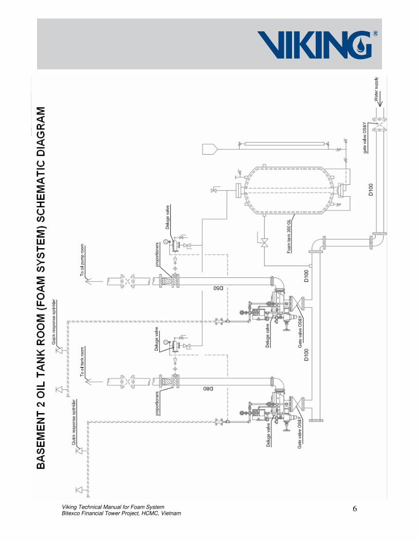
FOR BASEMENT 2 AND LEVEL 7, OIL TANK ROOM:
1. Installation: 2 piping line, First Line (1) is the Sprinkler head (Up-right), for fire
detecting inside the respective room, Second Line (2) is the Foam Discharge Nozzle
(Pendent), for discharging of water & foam concentration.
2. Discharge Sequence: Automatic from the Heat Detecting Line, once the Sprinkler
Heads exploded, the Priming Line will release the water from the Priming Chamber,
allowing the Deluge Valve Clapper to open and the Water will flow thru the inlet
Chamber, in the same time the water will discharge to the outlet piping, then the Foam
Deluge Valve Clapper will also open so that the Foam will flow thru, all equipment
consist in the foam system are hydraulically operated, once water flows to the deluge
valve assembly all equipment would function at the same time, the water and foam will
meet on the proportioner, which it will be discharge to the installed nozzle above the Oil
Tank Room. Together with the Water from Sprinkler Head and Mix Water & Foam from
the Discharge Nozzle, the foam will last with the standard NFPA time of 10 minutes.

Viking Technical Manual for Foam System Bitexco Financial Tower Project, HCMC, Vietnam
5
Manual Release Station, once the open valve was been activated, the priming line will
realease pressurized water to the piping outlet, and the priming chamber of the Deluge
Valve will open both Foam and Water Line, same as the operation for Automatic,
difference is only the manual release station will operated manually.
3. Pressurization, the Foam System and Equipments are pressurized by the Zone 1, Fire
Pump for Boosting Water; pressurizing the Foam Tank and the Deluge Foam System
Manifold.
4. Pressurization of the Foam Bladder Tank, once the Boosting of Water from Zone 1
Fire Pump, automatically the Foam Bladder Tank would receive pressure and make the
whole tank ready for Foam discharge, when it is activated.
5. Deluge Valve Assembly works as the main heart of the system: The following
specifications:
a. This equipment function is to detect fire from pilot line, means (Sprinkler Heads
installed, once the SP heads explode due to the fire), the priming line will drops its
pressure, then (1) the Halar Coated Concentrate, Control Valve will slowly open for
water to come up to the deluge valve, and (2) the Angle Coated Concentrate Control
Valve will slowly open the Foam supply line.
b. The item (1) Water and (2) Foam will mix to the Foam Proportiner or means
Concentrate Controller, where water and foam will mix together, and will go to the
discharge pendent nozzle inside the room.
c. Disharge Sequence (1) Manual Pull Station and (2) Automatic Release Heat Detectors.
6. Foam Concentrate, a water flow concentrate controller utilizing balanced pressure
injection, the controller is UL / FM Listed device to perform the task of Foam Mixing
accordingly, As water passes through the inlet nozzle, pressure is reduced in the annular
area of the nozzle. This reduction allows the metering of foam concentrate into the water
stream through a foam concentrate-metering orifice.
Viking Technical Manual for Foam System Bitexco Financial Tower Project, HCMC, Vietnam
6

Viking Technical Manual for Foam System Bitexco Financial Tower Project, HCMC, Vietnam
7

Viking Technical Manual for Foam System Bitexco Financial Tower Project, HCMC, Vietnam
8
FOR LEVEL 50, HELIPAD DECK AREA:
1. Installation
a. Foam Hose reel, fire fighting uses hose and discharging water and foam concentration.
b. Foam Oscillating Monitor, for discharging foam concentration with a given radius
automatically turn as designated for fire fighting operation.
2. Discharge Sequence: Solenoid Valve Assembly was been installed on the Entry and
Exit Door of Level 50, this would serve as the activating and triggering devices for the
Foam System installed at the Helipad Deck, once the Solenoid Valve is energized, it
would trigger the Priming Line to release pressurized water from the Priming Chamber of
the deluge valve, the water will flow to the outlet piping, and the deluge inlet piping will
let water flow thru, activating all hyradaulic equipment to function, at the same time the
Priming Line of the Foam Deluge Valve will open the Foam Piping from the Foam Tank,
allowing water and foam mix together in the Foam Proportioner, discharging to the Foam
Hose Reel and Foam Ocsillating Monitor, located at level 50 Helipad Deck Area.
The Manual Release Station can be found at the Level 49 floor, right beside the Deluge
Valve Assembly, once this the manual station is activated, the deluge valve will release
the pressurized priming line water to the outlet piping and will make the system
operational, to discharge foam in the level 50 Helipad Deck Area.
3. Pressurization of the Foam System and Equipments, at Level 49 floor, a 2,500 Liter
Capacity of Water Panel Tank was installed and 2 Jockey Pump for boosting pressurized
water to the Foam Bladder Tank and Foam System Manifold.
4. Pressurization of the Foam Bladder Tank, once the Boosting of Water from Level 49
Jockey Pump, automatically the Foam Bladder Tank would receive pressure and make
the whole tank ready for Foam discharge, when it is activated.

Viking Technical Manual for Foam System Bitexco Financial Tower Project, HCMC, Vietnam
9
5. Located at Level 50, Main Entrance Door, the Foam Pull station can be found, attach
to the crash kit cabinet, both doors of entrance and exit, this would be the discharge
sequence for the Foam System once it is activated. “DO NOT TOUCH the pull station, if
fire fighting is not needed.
6. Deluge Valve Assembly works as the main heart of the system: The following
specifications:
a. This equipment function is to detect fire from pilot line, means (Sprinkler Heads
installed, once the SP heads explode due to the fire), the priming line will drops its
pressure, then (1) the Halar Coated Concentrate, Control Valve will slowly open for
water to come up to the deluge valve, and (2) the Angle Coated Concentrate Control
Valve will slowly open the Foam supply line.
b. The item (1) Water and (2) Foam will mix to the Foam Proportiner or means
Concentrate Controller, where water and foam will mix together, and will go to the
discharge pendent nozzle inside the room.
c. Disharge Sequence (1) Manual Pull Station and (2) Automatic Release Heat Detectors.
7. Foam Hose Reel Station
Viking’s foam hose reel station is a self- contained unit that relies only on water flow and
pressure to place the system into operation. It is designed to be installed in a fixed
location such as Helidecks, offshore processing, storage or handling areas where it is
used to control fires or spills of flammable or combustible liquids. The continuous flow
hose reel is equipped with booster hose and hand line nozzle. It allows instant, single-
person operation; only unreel the amount of hose required and manually rewind.
Viking Technical Manual for Foam System Bitexco Financial Tower Project, HCMC, Vietnam
10
8. Foam Ocsillating Monitor
The Water-Powered Oscillating Monitor provides unparalleled performance with simple,
yet rugged design features in a very compact package. The monitor is designed to provide
an oscillating water or foam stream over a preset area of protection. The monitor can be
supplied with either an integral non-aspirating or air-aspirating nozzle.
The Water-powered oscillating monitors are commonly used for under wing protection in
aircraft hangars, helipads, loading racks and dike protection. They can also be used in
marine applications such as docks and offshore platforms.
Monitor shall be automatic oscillating type, requiring only water or foam solution inlet
pressure to provide power to drive oscillator mechanism. The monitor shall be fabricated
of cast brass and stainless steel, with all oscillating components constructed of brass and
stainless steel for corrosion resistance and wear. Monitor inlet connection shall be a side
mounted 2" grooved pipe.
Elevation and depression shall be infinitely adjustable from 45o below horizontal to 60o
above horizontal and shall be maintained by a locking mechanism. Elevation lock shall
incorporate a quick release for manual operation which, when re-engaged, locks elevation
in original setting.

Viking Technical Manual for Foam System Bitexco Financial Tower Project, HCMC, Vietnam
11
Viking Technical Manual for Foam System Bitexco Financial Tower Project, HCMC, Vietnam
12
3. Helpful Technical Description:
Deluge Bladder Tank Foam System is a standard deluge system capable of discharging a
foam solution automatically through open sprinklers, spray nozzles, monitor nozzles and
other discharge devices. A Deluge Bladder Tank Foam System with a Hydraulically
Concentrate Control Valve consist of a standard Deluge system using Deluge Valve
complete with full standard trim and detection and releasing devices, a Ratio Flow
Controller with appropriately sized orifice, a Hydraulically Concentrate Control Valve on
foam concentrate line, a foam concentrate Bladder Tank and trim and foam agent.
Activation of the electric release relieves the pressure in the priming chamber of both
Deluge Valve and Hydraulically Concentrate Control Valve. The system is then filled
with water, activating connected alarms and pressurizing the Bladder Tank. System water
pressurises the space between the flexible bladder and the inside surface of the steel tank,
causing the bladder to collapse and force the foam concentrate out through the discharge
pipe, hydraulic Concentrate Control Valve, the Ratio Flow Controller, into the Ratio
Flow Controller. The foam concentrate is in the proportion 3% of the supplied water.
The foam water solution is then sent to the discharge devices downstream.
The system shall be installed in accordance with the following standards:-
NFPA 16, Standard for the Installation of Deluge Foam-Water Sprinkler and Foam Water
Spray Systems,
NFPA 11, Standard for Low Expansion Foam,
NFPA 13, Standard for Installation of Sprinkler Systems and occupancy standard.
Actuation of the release line (pneumatic, hydraulic or electric) relieves the pressure in the
priming chamber of both the deluge valve and the concentrate control deluge valve. This
allows both valves to open. The system then fill’s with water, activating connected
alarms and pressurizing the bladder tank. The resulting water pressure in the space
between the flexible bladder and the inside surface of the steel tank, causes the bladder to
collapse, forcing the foam concentrate through discharge pipe work , hydraulic
Concentrate Control Valve, the Ratio Flow Controller, into the Ratio Flow Controller.
The foam concentrate is in the proportion usually 3% of the supplied water. The foam
water solution is then sent to the discharge devices downstream.

Viking Technical Manual for Foam System Bitexco Financial Tower Project, HCMC, Vietnam
13
3% AFFF Foam Concentrate
3% AFFF Foam Concentrate is a specially formulated, synthetic, aqueous film forming
foam concentrate. A vapor suppressing aqueous film is formed by the foam solution
draining from the expanded foam blanket. It is intended for use at a proportioning rate of
3% (3 part AFFF concentrate to 97 part water) on Class B hydrocarbon type fuels such as
gasoline, kerosene, diesel, etc. 3% AFFF is not intended for use on fuels which are polar
solvent/water miscible such as alcohols, ketones, esters, etc.
3% AFFF Foam Concentrate shall be UL listed and suitable for use with fresh or salt
water. It is suitable for use with carbon steel, fibre glass, polyethylene or stainless steel.
3% AFFF Foam Concentrate is not compatible with galvanized pipe or fittings in an
undiluted form. 3% AFFF foam concentrate shall have pH of 7.7, viscosity of 1.5 cps and
specific gravity of 1.02.
Bladder Tank
Vertical Bladder Tanks are designed and constructed in accordance with the latest
revision of ASME code, Section VIII for unfired pressure vessels with a working
pressure of 175 Psi and tested to 1.3 times this pressure.
The tank shell is constructed of steel, complying with ASME specifications, possessing a
tensile strength of not less than 70,000 psi. The circumference, as well as the longitudinal
body seams are machined welded. All welds and edges are to be ground smooth.
The tank inlet and tank outlet are to be screened to prevent bladder blow out or the
entrapment of debris between the tank shell and the bladder.
Four legs are provided for support and anchoring the vertical Bladder tank assembly and
for access to the bladder drain/fill valve and the tank shell drain/fill valve.
Rubber Bladder is manufactured of a vinyl based polymer, or polyester reinforced
copolymer. The bladder material shall have an ASTM D-412 Tensile Strength of at least
3,000 Psi and an ASTM D-624 Graves Tear Strength of at least 420 lbs/in.
Bladder Tank shall be UL Listed.

Viking Technical Manual for Foam System Bitexco Financial Tower Project, HCMC, Vietnam
14
Ratio- Flow Controller
Ratio Flow Controller is a device designed to meter the correct amount of foam
concentrate into the water stream over a wide range of flows and pressures with minimal
pressure loss. These devices are used in conjunction with Vertical Bladder Tank. Ratio
Flow Controllers are UL Listed and FM Approved. The operating principle of the
controller is based upon the use of a modified venturi. As water passes through the inlet
nozzle, pressure is reduced in the annular area of the nozzle. This reduction allows the
metering of foam concentrate into the water stream through a foam concentrate-metering
orifice.
Ratio Flow Controller body is cast from ASTM 85-5-5-5 brass Inlet nozzle and metering
orifice are machined from SAE #72 Brass. The inlet nozzle set screws and metering
orifice retaining ring are of stainless steel.
The inlet nozzle is secured by two stainless steel set screws. This allows the nozzle to be
removed from the controller for cleaning and/or repair.
Metering orifices are sized appropriately for each specified type and percentage foam
concentrate. A stainless steel retaining ring secures the orifice in place.
Controller body is clearly marked with a flow direction arrow and label to identify the
type of foam concentrate and injection percentage ratio.
Hydraulic Concentrate Control Valve
The standard hydraulic actuated valve assembly consist of a factory assembled and tested
quarter turn full port ball valve to which a hydraulic actuator has been attached. The ball
valve has a bronze body with a 316 stainless steel ball and stem, or is of all stainless steel
construction. Valve seats are glass-reinforced TFE. Inlet and outlet threads are female
NPT and flanges are ANSI Class 150. All valves are rated 600 Psi WOG. Stainless steel
flanged valves are rated 285 Psi WOG.
The hydraulic actuator is mounted directly to the ball valve using a mounting bracket.
The housing of the actuator has a corrosion resistant exterior with a two-part epoxy
coating providing extra protection against aggressive environments. The interior has a
long life epoxy or of PTFE finish protecting all body parts against wear and corrosion.

Viking Technical Manual for Foam System Bitexco Financial Tower Project, HCMC, Vietnam
15
The hydraulic actuator is equipped with a visual valve position indicator and has the
capability for manual override using a free handle, secured to the valve body with a
length of chain. Water to drive the valve open is fed to the hydraulic actuator through ¼”
to ½” pipe. A connection from the sprinkler system is usually made from a normally un-
pressurized port such as the water motor alarm line on the Deluge Valve to power the
hydraulic actuator. The water inlet to the hydraulic actuator is provided with a “Y”
strainer and shut-off valve to allow depressurizing and resetting of the valve after use.
Normal operating pressure range of the Hydraulic Concentrate Control Valve is 40 to 120
Psi and maximum actuator overload pressure is 200 Psi.
Foam Concentrate Piping
Foam Concentrate piping shall be compatible with foam concentrate to be used. Foam
provider shall be consulted for acceptable material of construction. Foam concentrate
piping shall be designed for the least equivalent feet of pipe run from bladder tank
discharge outlet to proportioning device and water supply to bladder tank. Excessive use
of elbows and tees shall be avoided. Foam concentrate piping shall be substantially
secured and restrained against movement, thrust and vibration. Foam concentrate piping
shall be protected from excessive heat. Foam concentrate piping shall be installed with
union to be readily removed between proportioning valve assembly and concentrate
control valve
Riser Test Connection
A test connection shall be provided on the system riser with a downstream isolation valve
for the purpose of testing foam proportioning. System test header shall be of adequate
size for at least a mid range flow of the proportioning system.
System Control Valve (OS&Y Gate Valve)
The system control valve shall be a listed type valve. The control valve shall be UL
Listed or FM Approved for fire protection installation. The system control valve shall be
rated for normal system pressure but in no case less than 175 Psi.

Viking Technical Manual for Foam System Bitexco Financial Tower Project, HCMC, Vietnam
16
Deluge Valve
Deluge systems shall utilize a 90-degree pattern. Deluge Valve shall be able to reset
externally. Deluge valve shall employ a positive vent on the priming line to ensure that
the Deluge Valve will not prematurely reset. Inlet and outlet connection of Deluge Valve
shall be flange-by-flange connection. The Deluge Valve shall be capable of installation in
the vertical or horizontal position. Deluge Valve shall be UL Listed and FM Approved.
Working Pressure of Deluge Valve shall be 250 Psi. The valve trim shall be compatible
and shall be installed following the manufacturer’s specification.
Deluge Valve Conventional Trim
Deluge Valve trim shall incorporate pressure operated relief valve (PORV), to provide a
hydraulic means to positively vent the priming water chamber. All deluge valve trim
piping and devices shall be listed for use as Deluge System. Deluge valve trim shall be
galvanized and rated for 250 Psi working pressure. Deluge Valve trim shall be
compatible with Deluge Valve.
Release Control Panel
Deluge valve release panel shall be 220VAC powered with a 24 hour D/C backup power
supply. Deluge Valve release control panel shall conform to NFPA 70, NFPA 72 and all
other applicable codes. Release control panel shall be listed for use with Deluge Valve.
Spray Nozzles
Spray Nozzles are open type spray nozzles designed for directional spray application in
fixed fire protection systems. They have an open design with an external deflector that
discharges a solid uniform cone spray of low-to-medium velocity water droplets. Spray
nozzles are available in multiple orifice sizes and spray angles to meet design criteria and
include ½” NPT external pipe thread. Spray nozzle shall be UL Listed and FM approved.
Alarm Pressure Switch
Water flow will activate an alarm by way of an alarm pressure switch. The alarm pressure
switch shall be UL Listed and FM Approved for the application in which it is used.

Viking Technical Manual for Foam System Bitexco Financial Tower Project, HCMC, Vietnam
17
Water Motor Alarm
Water flow will activate a hydraulic powered water motor alarm by way of integral valve
alarm line trim piping. The water gong shall be connected to a retarding chamber to limit
the possibility of unnecessary alarms. The water motor alarm shall be equipped with a
rear closure plate to limit the access of foreign material and accumulation of debris. The
water motor alarm shall be UL Listed and FM Approved.
Detection System
Quick Response Sprinkler shall be used as detection system to trip the Deluge Valve.
When the Quick Response Sprinkler activates, it will cause the priming chamber of the
Deluge Valve to lose pressure and thereby causing the lower chamber of the Deluge
Valve to lift the diaphragm of the Deluge and discharge water from the riser pipe into to
the Oil Tank Room.

Viking Technical Manual for Foam System Bitexco Financial Tower Project, HCMC, Vietnam
18