training manual - jordan valve - jordan valve … · 4 training manual jordan valve 4 jordan valve:...
TRANSCRIPT

TRAINING MANUAL

TRAINING MANUAL2 JORDANVALVE
2
3JORDANVALVE
3
ContentsJordan Valve: A General Profile ...........................................................4-5
Key Concepts ....................................................................................... 6-23
Regulator Overview ..........................................................................24-31
Regulator Sizing .................................................................................32-40
Back Pressure Regulator Overview ......................................................41
Temperature Regulator Overview .................................................42-51
Tank Blanketing Overview ..............................................................52-56
Control Valve Overview ...................................................................57-69
Applications ........................................................................................70-99
Jordan Valve Competition .......................................................... 100-113
Pressure Regulator Selection..................................................... 114-126
Back Pressure Regulator Selection .......................................... 127-134
Temperature Regulator Selection ............................................. 135-141
Tank Blanketing Selection .......................................................... 142-154
Control Valve Overview .............................................................. 155-170
TRAINING MANUAL4 JORDANVALVE
4
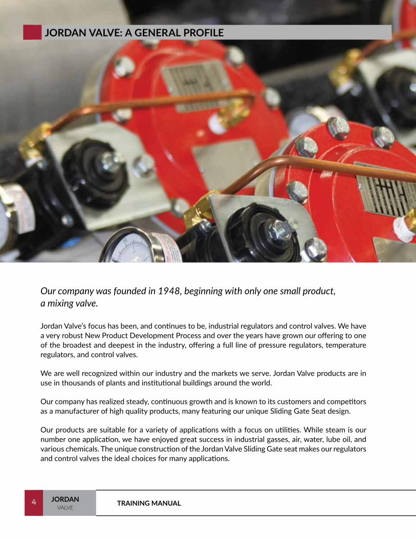
JORDAN VALVE: A GENERAL PROFILE
Our company was founded in 1948, beginning with only one small product, a mixing valve.
Jordan Valve’s focus has been, and continues to be, industrial regulators and control valves. We have a very robust New Product Development Process and over the years have grown our offering to one of the broadest and deepest in the industry, offering a full line of pressure regulators, temperature regulators, and control valves.
We are well recognized within our industry and the markets we serve. Jordan Valve products are in use in thousands of plants and institutional buildings around the world.
Our company has realized steady, continuous growth and is known to its customers and competitors as a manufacturer of high quality products, many featuring our unique Sliding Gate Seat design.
Our products are suitable for a variety of applications with a focus on utilities. While steam is our number one application, we have enjoyed great success in industrial gasses, air, water, lube oil, and various chemicals. The unique construction of the Jordan Valve Sliding Gate seat makes our regulators and control valves the ideal choices for many applications.
5JORDANVALVE
5
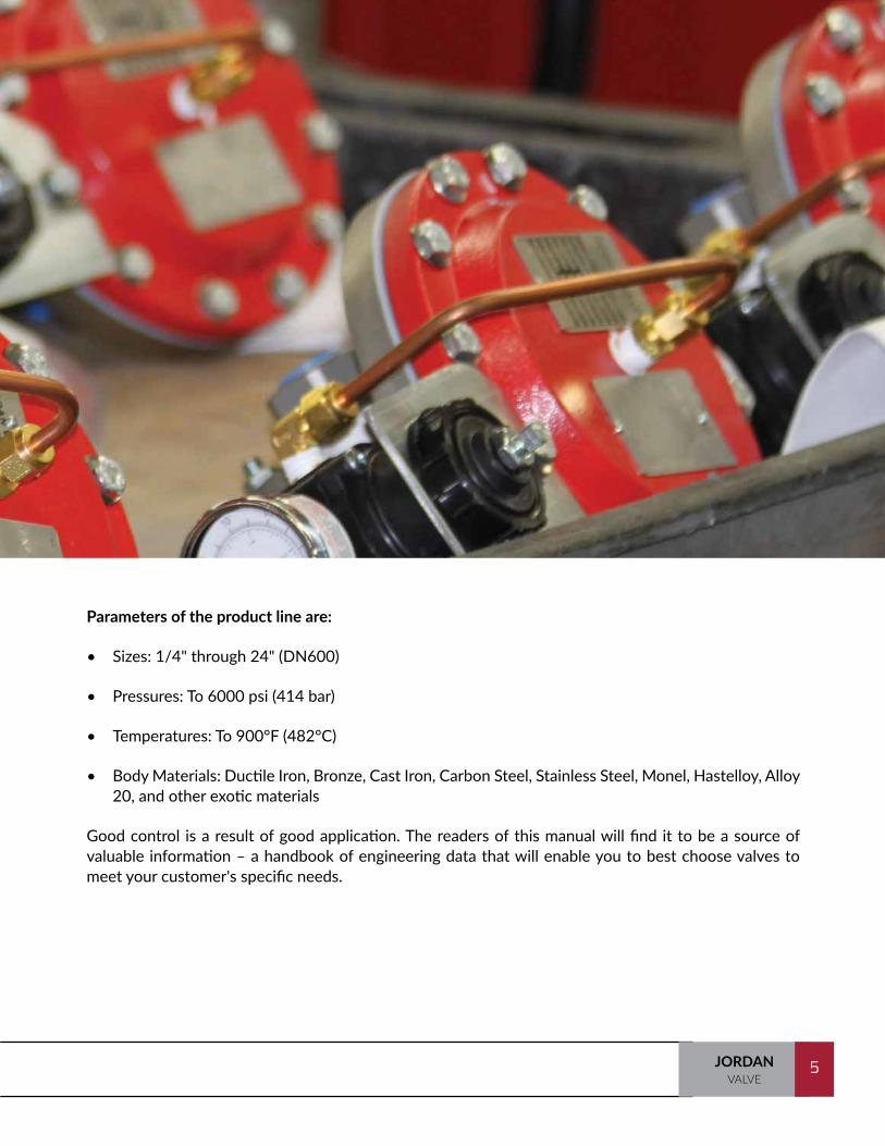
Parameters of the product line are:
• Sizes: 1/4" through 24" (DN600)
• Pressures: To 6000 psi (414 bar)
• Temperatures: To 900°F (482°C)
• Body Materials: Ductile Iron, Bronze, Cast Iron, Carbon Steel, Stainless Steel, Monel, Hastelloy, Alloy 20, and other exotic materials
Good control is a result of good application. The readers of this manual will find it to be a source of valuable information – a handbook of engineering data that will enable you to best choose valves to meet your customer's specific needs.

TRAINING MANUAL6 JORDANVALVE
6
AN INTRODUCTION TO REGULATORS AND CONTROL VALVES
Valves are probably the oldest form of control known to man. There are many valves on the market today, but none really differ from the valve first built by the Egyptians for irrigation purposes in their fields.
A valve is no more than a variable orifice, which controls flow. Whether Ball, Knife, Gate, Globe, or Sliding Gate, all valves control flow as a function of pressure, temperature, level, or flow itself.
There are so many types of valves that an understanding of their capabilities and shortcomings is important. Proper specification and application of valves can save your customer a great deal of money initially and also prevent unnecessary headaches for maintenance staff.
It is intended that this introduction to pressure and temperature regulation will provide you with the information you will need to:
• Determine the applications for which pressure and temperature regulators and control valves are designed
• Understand the basic features and benefits of each
• Determine if a self-operated or pilot-operated pressure regulator, temperature regulator, or control valve will provide your customer with the control needed at a cost-effective price

7JORDANVALVE
7
INTRODUCTION TO KEY CONCEPTS
The following section, Key Concepts, addresses Droop, Tight Shutoff, Rangeability, and the Jordan Valve Sliding Gate Seat. A thorough understanding of these concepts is crucial to your understanding of the Jordan Valve product offering.
When selling or specifying industrial regulators and control valves, there are a few key definitions that must be understood. You should have a thorough knowledge of these before any attempt is made to explain them to a customer.
Accuracy: A term used to denote the exact reliability of a measuring instrument to show the true value or true amount of the measured element. Accuracy is usually expressed as a percentage of the full scale reading of the instruments.
ANSI: American National Standards Institute is a private nonprofit organization that oversees the development of voluntary consensus standards for products, services, processes, systems, and personnel.
Control Valve: A valve which regulates the flow or pressure of a medium which affects a controlled process. Control valves are operated by remote signals from independent devices using any of a number of control media such as pneumatic, electric, electro-hydraulic.
Droop: Droop is an inherent characteristic of all self-operated and pilot-operated regulators. Also known as Proportional Band or Offset, droop is defined as the deviation from setpoint as flow increases through a regulator.
FCI: Fluid Controls Institute focuses on technical issues, and provides standards and educational materials to assist purchasers and users in understanding and using fluid control and conditioning equipment.
Lock-Up: The pressure above setpoint that is required to shut the valve off tight.
Rangeability: The ratio of maximum flow to minimum flow that a valve can pass before control becomes affected. In other words, this is the total flow range of the valve in which we can expect proper control.
Regulator: A simple self-operated control device, which operates off of the process itself. This is basically a force balance mechanism.
Set Point: A target value which automatic control devices attempt to reach or hold.
Valve: A device which controls fluid flow direction, pressure, or flow rate.
TRAINING MANUAL8 JORDANVALVE
8
KEY CONCEPTS
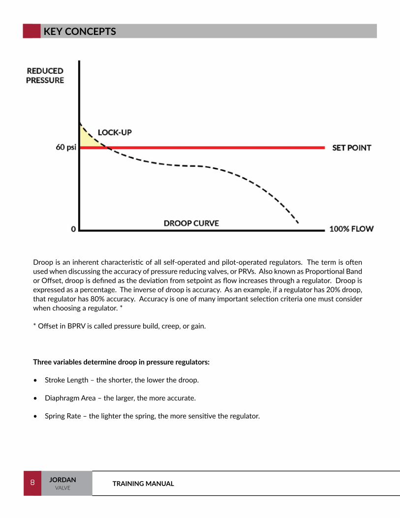
Droop is an inherent characteristic of all self-operated and pilot-operated regulators. The term is often used when discussing the accuracy of pressure reducing valves, or PRVs. Also known as Proportional Band or Offset, droop is defined as the deviation from setpoint as flow increases through a regulator. Droop is expressed as a percentage. The inverse of droop is accuracy. As an example, if a regulator has 20% droop, that regulator has 80% accuracy. Accuracy is one of many important selection criteria one must consider when choosing a regulator. *
* Offset in BPRV is called pressure build, creep, or gain.
Three variables determine droop in pressure regulators:
• Stroke Length – the shorter, the lower the droop.
• Diaphragm Area – the larger, the more accurate.
• Spring Rate – the lighter the spring, the more sensitive the regulator.
9JORDANVALVE
9
Different regulator designs can provide more accurate regulation (less droop)*:
• Self-operated: 10% - 30% droop
• Pilot operated regulators: 5% - 10% droop
• Dome loaded valves: 2% - 5% droop. Accuracy is very high due to the elimination of the spring.
If flow demands are relatively constant, or 10-30% deviation from set point is tolerable, a self-contained regulator should be used.
If the flow fluctuations are great, or accuracy is essential, it may be necessary to go to pilot-operated valves.
If you are considering using a control valve to control pressure, determine if a regulator would be accurate enough for pressure reduction applications.
General Rules
• A piloted regulator has less droop than a direct-operated regulator.
• Air loaded regulators are much more accurate because there is no spring. In some models, droop is virtually eliminated.
• High-flow regulators are less accurate than standard regulators.
• Typically, the shorter the overall stroke, the less the amount of Droop.
• Larger diaphragms will increase overall accuracy.
• Regulators supplying a medium to multiple users/vessels will be less accurate than regulators supplying a medium to a single unit/vessel.
• The set point should be toward the high end of the selected spring range to give increased accuracy of regulation.
Performance calculators (droop and build up) are available for the Mark 60 and Mark 50 in the Member Login section of the Jordan Valve website. Contact your Jordan Valve Client Consultant for help with other models.
* These are approximate values. Actual performance will vary based on application parameters.

TRAINING MANUAL10 JORDANVALVE
10
FORMULA FOR CALCULATING DROOP
R = Spring Rate
P1 = Inlet Pressure
SF = Seat Friction
A = Area
P2 = Outlet (Set) Controlled Pressure
S = Stroke
F = Force
P2 x A = F
Droop - ((P2 x A1) - (S x R)) / A2
A1 = Initial Diaphragm Area
A2 = Final Diaphragm Area
Spring Rate = Pounds Per Inch
11JORDANVALVE
11
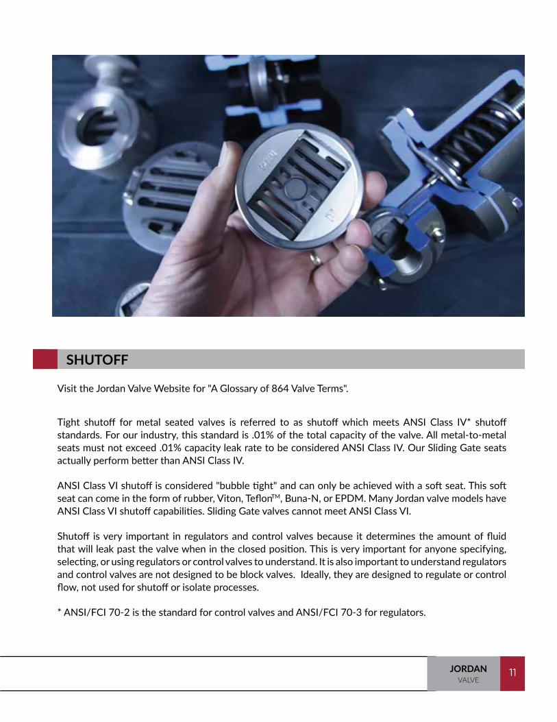
SHUTOFF
Visit the Jordan Valve Website for "A Glossary of 864 Valve Terms".
Tight shutoff for metal seated valves is referred to as shutoff which meets ANSI Class IV* shutoff standards. For our industry, this standard is .01% of the total capacity of the valve. All metal-to-metal seats must not exceed .01% capacity leak rate to be considered ANSI Class IV. Our Sliding Gate seats actually perform better than ANSI Class IV.
ANSI Class VI shutoff is considered "bubble tight" and can only be achieved with a soft seat. This soft seat can come in the form of rubber, Viton, TeflonTM, Buna-N, or EPDM. Many Jordan valve models have ANSI Class VI shutoff capabilities. Sliding Gate valves cannot meet ANSI Class VI.
Shutoff is very important in regulators and control valves because it determines the amount of fluid that will leak past the valve when in the closed position. This is very important for anyone specifying, selecting, or using regulators or control valves to understand. It is also important to understand regulators and control valves are not designed to be block valves. Ideally, they are designed to regulate or control flow, not used for shutoff or isolate processes.
* ANSI/FCI 70-2 is the standard for control valves and ANSI/FCI 70-3 for regulators.
S = Stroke

TRAINING MANUAL12 JORDANVALVE
12
ALLOWABLE LEAK RATES
Allowable Leak Rates for ANSI / FCI 70-2 and ANSI / FCI 70-3
It is important to note these standards apply to production tests and cannot be used as a basis for predicting leakage conditions other than those specified. Be sure to refer to these standards for test medium, pressures, temperatures and duration.
ANSI / FCI 70-2
Control Valve Seat Leakage1
Leakage Class Maximum Seat Leakage
Class I A modification of any Class II, III or VI valve where design intent is the same as the basic class, but by agreement between user and supplier, not test is required.
Class II 0.5% of rated valve capacityClass III 0.1% of rated valve capacityClass IV 0.01% of rated valve capacity
Class V
5 x 10⁻⁴ minute of water per inch of seat diameter per psi differential5 x 10-12 m3 per second of water per mm of seat diameter per bar differential
4.7 standard ml per minute of air per inch of orifice diameter11.1 x 10-6 standard m3 per hour of air per minute versus seat diameter
Class VIWith control valve adjusted to meet the operating conditions specified and with
sufficient time allowance for stabilizing flow, the leak rate shall not exceed the values in the table below.
Nominal Seat DiameterInches (Millimeters) ml per minute Bubbles per minute
≤ 1 (25) 0.15 11.5 (38) 0.30 22 (51) 0.45 3
2.5 (64) 0.60 43 (76) 0.90 6
4 (102) 1.70 116 (152) 4.00 278 (203) 6.75 45
10 (250) 11.1 -12 (300) 16.0 -14 (350) 21.6 -16 (400) 28.4 -
13JORDANVALVE
13
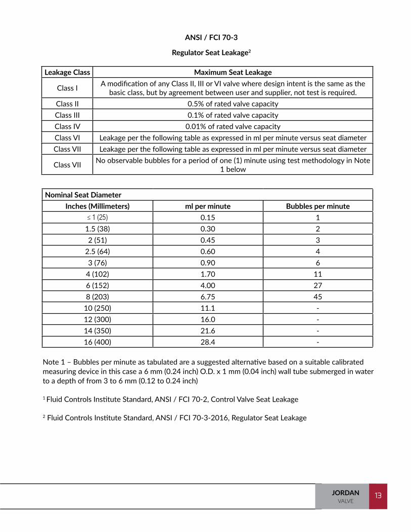
ANSI / FCI 70-3
Regulator Seat Leakage2
Note 1 – Bubbles per minute as tabulated are a suggested alternative based on a suitable calibrated measuring device in this case a 6 mm (0.24 inch) O.D. x 1 mm (0.04 inch) wall tube submerged in water to a depth of from 3 to 6 mm (0.12 to 0.24 inch)
1 Fluid Controls Institute Standard, ANSI / FCI 70-2, Control Valve Seat Leakage
2 Fluid Controls Institute Standard, ANSI / FCI 70-3-2016, Regulator Seat Leakage
Leakage Class Maximum Seat Leakage
Class I A modification of any Class II, III or VI valve where design intent is the same as the basic class, but by agreement between user and supplier, not test is required.
Class II 0.5% of rated valve capacityClass III 0.1% of rated valve capacityClass IV 0.01% of rated valve capacityClass VI Leakage per the following table as expressed in ml per minute versus seat diameterClass VII Leakage per the following table as expressed in ml per minute versus seat diameter
Class VII No observable bubbles for a period of one (1) minute using test methodology in Note 1 below
Nominal Seat DiameterInches (Millimeters) ml per minute Bubbles per minute
≤ 1 (25) 0.15 11.5 (38) 0.30 22 (51) 0.45 3
2.5 (64) 0.60 43 (76) 0.90 6
4 (102) 1.70 116 (152) 4.00 278 (203) 6.75 45
10 (250) 11.1 -12 (300) 16.0 -14 (350) 21.6 -16 (400) 28.4 -

TRAINING MANUAL14 JORDANVALVE
14
RANGEABILITY
Turndown ratio, or rangeability, is the ratio of maximum flow to minimum flow that a valve can pass before control becomes affected. In other words, this is the total flow range of the valve in which we can expect proper control.
Rangeability is very important in determining what type of valve to use for a given service. Self- Operated valves can have turndowns ranging from 10-20:1, depending upon the manufacturer. Pilot-operated valves can go anywhere from 35-50:1. Controller-operated valves can go as high as 100:1 or even greater.
One key to specifying the right valve for a particular application is in the maximum and minimum flows that are required.
Example: If a heat exchanger has a maximum capacity of 100 gpm and a minimum capacity of 10 gpm, the rangeability required from the valve to the heat exchanger will be 10:1.
For this application, it would be ideal to use a self-operated valve mainly because it is much less expensive, easier to maintain, and will provide the proper control for the application.
However, if the maximum capacity of the heat exchanger was 300 gpm and the minimum flow capacity was 10 gpm, we would have a 30:1 turndown requirement. At 30:1, we are taxing the ability of a regulator to control properly at the extremes, and it would be best to recommend a pilot-operated valve, or an air-loaded regulator.
For 500 gpm maximum and 10 gpm minimum, the turndown ratio would be 50:1. In this case, a control valve would be needed.
You can see that it is not difficult to determine which type of valve is best for an application as long as the rangeabilities are known. Once this is known, you need to determine which particular model will provide you the best service.
You can see from the example that control comes in a wide variety of valve types. There are self- operated regulators, pilot-operated valves, air-operated control valves, and electric operated control valves, all of which will be studied in this manual.
15JORDANVALVE
15
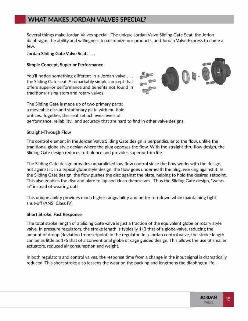
performance, reliability, and accuracy that are hard to find in other valve designs.
Straight-Through Flow The control element in the Jordan Valve Sliding Gate design is perpendicular to the flow, unlike the traditional globe style design where the plug opposes the flow. With the straight thru flow design, the Sliding Gate design reduces turbulence and provides superior trim life.
The Sliding Gate design provides unparalleled low flow control since the flow works with the design, not against it. In a typical globe style design, the flow goes underneath the plug, working against it. In the Sliding Gate design, the flow pushes the disc against the plate, helping to hold the desired setpoint. This also enables the disc and plate to lap and clean themselves. Thus the Sliding Gate design, "wears in" instead of wearing out!
This unique ability provides much higher rangeability and better turndown while maintaining tight shut-off (ANSI Class IV).
Short Stroke, Fast Response The total stroke length of a Sliding Gate valve is just a fraction of the equivalent globe or rotary style valve. In pressure regulators, the stroke length is typically 1/3 that of a globe valve, reducing the amount of droop (deviation from setpoint) in the regulator. In a Jordan control valve, the stroke length can be as little as 1/6 that of a conventional globe or cage guided design. This allows the use of smaller actuators, reduced air consumption and weight.
In both regulators and control valves, the response time from a change in the input signal is dramatically reduced. This short stroke also lessens the wear on the packing and lengthens the diaphragm life.
WHAT MAKES JORDAN VALVES SPECIAL?
Jordan Sliding Gate Valve Seats . . .
Simple Concept, Superior Performance
You’ll notice something different in a Jordan valve . . . the Sliding Gate seat. A remarkably simple concept that offers superior performance and benefits not found in traditional rising stem and rotary valves.
The Sliding Gate is made up of two primary parts: a moveable disc and stationary plate with multiple orifices. Together, this seat set achieves levels of
Several things make Jordan Valves special. The unique Jordan Valve Sliding Gate Seat, the Jorlon diaphragm, the ability and willingness to customize our products, and Jordan Valve Express to name a few.

TRAINING MANUAL16 JORDANVALVE
16
Quiet Operation Quiet operation is a standard benefit of Jordan Sliding Gate valves. Compared to conventional globe and cage designs, the Sliding Gate seat generates between 5-10 dBa less noise. In addition, you won’t find a premium price adder for “low-noise trim”. The Sliding Gate valve is inherently quieter than other types of valves because:
• The disc and plate remain in constant contact, eliminating the chatter found in plug and seat designs.
• The straight-through flow passage minimizes turbulence found in globe and rotary designs, a prime cause of valve noise.
• The multiple orifices in the plate and disc divide the flow into smaller, noise-dissipating flow streams.
Area of Closure The Sliding Gate design provides an area of closure, rather than the line of closure in a seat ring. When the valve is closed, the disc and plate are overlapped by 1/32" This area of closure helps reduce the effects of wire draw which is one of the most common causes of seat leakage. Wire drawing, which is often found in plug and seat ring designs, is the premature erosion of a valve seat caused by the excessive velocity of the medium (steam) between the valve seat and valve sealing member when the valve seat has been compromised or the valve is not fully closed. What does this mean? Less maintenance downtime and more opportunity to increase yields and profits!
17JORDANVALVE
17
• Self-cleaning – The movement of the Sliding Gate seats generates a self-cleaning action, with any leak-producing deposits being cleaned off by the sharp shearing action of the disc moving across the plate.
• Materials – Our proprietary Jorcote seat material is extremely hard and delivers outstanding wear resistance.
• Multi-orifice – The multi-orifice design separates erosive flow into smaller, less damaging streams. The erosive forces are dissipated over the numerous slots eliminating the single wear points associated with other valve types, and increased sealing areas, resulting in much longer seat life.
• Media assisted – The upstream pressure holds the disc in constant contact with the plate. This prevents the sudden, damaging (and noisy) contact which occurs in some plug/cage designs. The constant contact between the disc and plate actually generates a self-lapping effect, which results in less friction and tighter shutoff than when the valve leaves the factory in new condition.
Jordan Valve engineers conducted a steam test using 250 psig (17,2 barg) saturated steam. The test was designed so that the valve would fully stroke open and closed each time it was actuated. The pressure drop across the valve was the full 250 psig (17,2 barg). The results were impressive. Our standard Jorcote/Chrome seat combination had less friction after 70,000 cycles than when it was new and the seat leakage was still well below ANSI Class IV limits.
Result: Tighter shutoff than a brand new valve leaving the factory.
Seat Coatings
Jorcote, our standard seat material, is a proprietary composite coating on Stainless Steel. This material is extremely hard (@ RC85) and delivers outstanding performance. Factory testing at 250 psi steam shows that after over 70,000 full stroke cycles, Jorcote will still shutoff to ANSI Class IV leak limits. Other coatings include TeflonTM coating and chrome plating, good to 55°F.
Easy to Maintain
The simplistic design of the Sliding Gate valve makes maintenance easy to perform. Disassembly of the valve is very simple and, since the seats are not pressed or screwed into the valve body, they conveniently lift out. Should your flow requirements change, interchangeable Cv’s are available in flow coefficients as low as 0.0008 and as high as 395 (depending on body size).
WHY THE SLIDING GATE LASTS LONGER THAN OTHER DESIGNS:
TRAINING MANUAL18 JORDANVALVE
18
Size and Weight As the line sizes increase, so too does the size and weight of the valve. Because of the short stroke length, a Sliding Gate valve is typically shorter and lighter weight than a globe-style valve.
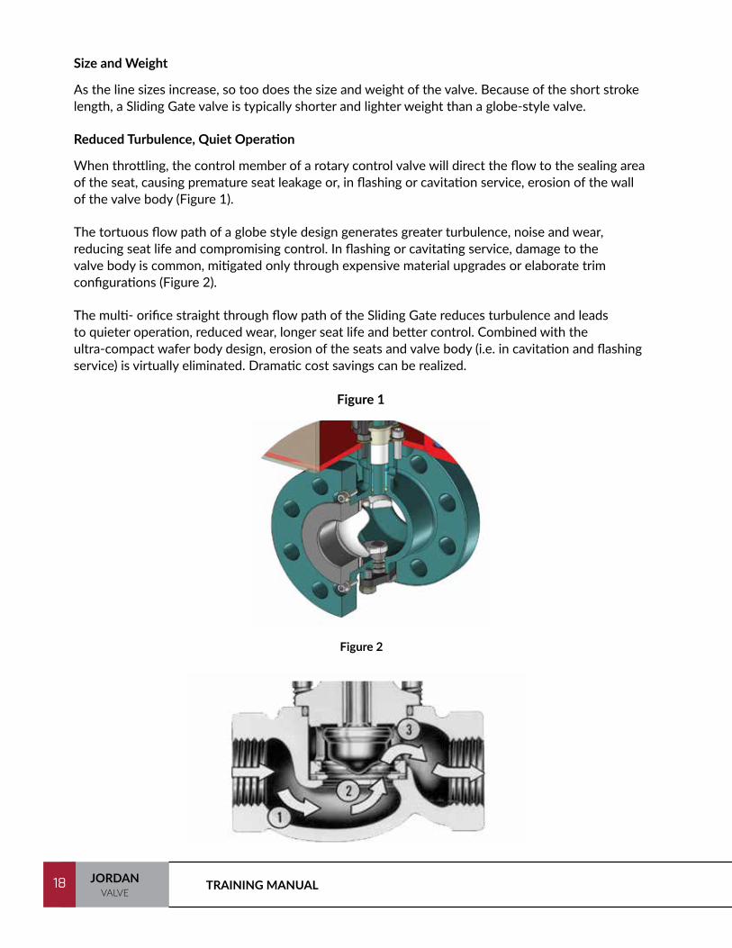
Reduced Turbulence, Quiet Operation When throttling, the control member of a rotary control valve will direct the flow to the sealing area of the seat, causing premature seat leakage or, in flashing or cavitation service, erosion of the wall of the valve body (Figure 1).
The tortuous flow path of a globe style design generates greater turbulence, noise and wear, reducing seat life and compromising control. In flashing or cavitating service, damage to the valve body is common, mitigated only through expensive material upgrades or elaborate trim configurations (Figure 2).
The multi- orifice straight through flow path of the Sliding Gate reduces turbulence and leads to quieter operation, reduced wear, longer seat life and better control. Combined with the ultra-compact wafer body design, erosion of the seats and valve body (i.e. in cavitation and flashing service) is virtually eliminated. Dramatic cost savings can be realized.
Figure 1
Figure 2

19JORDANVALVE
19
Jorlon is a proprietary chemically modified PTFE designed to minimize cold flow and creep. It positively impacts regulator reliability, performance, and service life. It is the standard, and preferred diaphragm, in most regulator applications and provides the following benefits:
• Chemical Compatibility : Jorlon is PTFE based and as such, compatible with the same media as TeflonTM
up to 450°F (232°C). It is not compatible with fluorinated gases and halogenated fluorocarbons. (See the chemical compatibility chart on the following page.)
• Improved Performance: Stainless Steel diaphragms by nature are rigid and therefore have decreased sensitivity. Jorlon approaches the droop performance seen in true elastomer diaphragms resulting in greater set point accuracy.
• Long Life: This material simply does not fail! Prior to the 2000 release of the Jorlon Diaphragm in Jordan Valve regulators, our engineers subjected them to a rigorous test regime. • We tested the Jorlon diaphragm for over 1 million full stroke cycles at 70 psi steam without failure. • We stopped our 225 psig, medium pressure test, at 258,000 full stroke cycles. No failure. • Subjected to the same test parameters, a stainless diaphragm failed at less than 2,000 cycles. • In a high pressure test, variable steam between 360 psig and 430 psig, we ended the test at 125,000 cycles without failure.
The durability and reliability of the Jorlon diaphragm, coupled with the unique Jordan Valve Sliding Gate seat, make Jordan Sliding Gate regulators the best value available in the market today.
JORLON DIAPHRAGM

TRAINING MANUAL20 JORDANVALVE
20
SPECIALS
Jordan Valves are highly engineered products. In addition to the standard Jordan product offering, we are willing and able to do special configurations and materials. Our Jordan Valve engineers welcome the opportunity to customize products for specific applications.
"S Number" - series of feature option picks that define the product structure
You can see in the chart above, we do not manufacture commodity valves by the thousands. We manufactured 4,502 unique engineered products in a 12 month period.

21JORDANVALVE
21
Always talk to your customers about Jordan Valve Express. We offer next day shipment on many valve and actuator models at no additional cost. Take advantage of this value-added sales tool. To see the wide variety of Jordan Valve products available for next business day shipping, look for the Jordan Valve Express logo on the Jordan Valve web site. Additional exceptions may apply.
To qualify for Jordan Valve Express, the following conditions must be met:
• 2 units max
• Standard Cv's
• Standard seats on Sliding Gate valves (Jorcote)
• Expedite freight required
• No traceable certs for Jordan Valve Express valves
• Specify Jordan Valve Express at time of order
End Connection Rules for Jordan Valve Express:
• Add 1 week for threaded flanges (150#, 300#, or PN40*)
• Add 2 weeks for welded flanges of ISO sanitary connections
• Jordan uses PN40 flanges when PN10/16/25/40 flanges are ordered. To meet DIN specification for PN40 pressure regulators, double bolting is required which eliminates them from the Jordan Valve Express.
Jordan Valve Express Next Business Day Valve - order must be received by 2:00 pm Eastern Standard Time Monday through Friday.
The following excerpt from the Jordan Valve Lead Time Matrix highlights those products included in the Jordan Valve Express program.
JORDAN VALVE EXPRESS

TRAINING MANUAL22 JORDANVALVE
22
Model Size Lead Time Detail
Mark 50/60 1/2" - 2" Next Business Day
SST/Jorlon diaphragm mtls, Std Cv and 1 reduction, FNPT end conn, HP option 2" and under, DIN Flanges for CS or SST bodies (DN25 to DN50), 150# ANSI Fl. for CS or SST bodies
Mark 501/502/601/602 2" Next Business
Day
Mark 51/61 All Next Business Day
FNPT end connection, SST/Jorlon Dia-phragm
Mark 53/63 All Next Business Day
SST/Jorlon diaphragm, FNPT, DIN DN25-50, 150# RF 1/" -2", Closing Caps
Mark 56/66 1/2" - 2" Next Business Day
DI & SS NPT valves only, all else 3 weeks
Mark 608 All Next Business Day
FNPT, SST Trim Only, Buna-N or Viton plug/diaphragm
Mark 70 All Next Business Day
Std actuators only, FNPT only, SMP (MK16IQ-S), DIN PN40 DN25-50 Flanges, ANSI 150 Flanges - CS/SST Bodies 1" - 2"; (1 week)
Mark 75 All Next Business Day
1" - 6", SST, STD CVs, SMP, Standard Actuator
Mark 78 All Next Business Day
Linear=%, Max CV/line size, Std actuator only, FNPT only, SMP (MK16IQ-S)
Mark 33 1/2" - 2" Next Business Day 24 VAC, FNPT only
Mark 37 1/2" - 2" Next Business Day
CML 100 Motor only, 120 VAC/240 VAC only, FNPT
Mark 80 All Next Business Day
Type A bulb only, Copper capillary, FNPT
Actuator Assembly 14M, 35M Next Business Day MK70/74: 1/2" - 2", 3-15 Rev/DIR
Lead Time Matrix

23JORDANVALVE
23
Plug Style
The plug and seat design allows for ANSI Class VI shutoff with a soft seat and will shut off flow from either side. If it has a cage-guided, bottom entry design, the valve can be repaired in-line (See Figure 1).
One disadvantage of the plug style valve is the wear on the plug that is accelerated by increases in velocity and turbulence caused by the many changes in direction through the flow path. It’s not recommended on steam service.
Sliding Gate Seats
The most unique pressure regulator on the market utilizes a Sliding Gate seat that is the standard seat design used in most of our valves. It operates on precisely the same principle as the plug and seat, but has many advantages because of its design, especially in steam and erosive liquid services.
Because the seat allows straight-through flow, the velocity, turbulence, noise, and erosiveness of the steam are all reduced because the lower velocity service is dissipated over the large surface area of the Sliding Gate’s multiple orifices (See Figure 2).
Since the disc portion of the Sliding Gate seat provides a 1/32" overlap in the closed position, Jordan valves provide excellent shutoff and leak rate characteristics. This additional seating surface not only provides tighter shutoff than globe valve, but also has a longer life because there’s an additional 1/32" of metal to erode before shutoff and control are affected.
Both seat designs have their strong points, and since we can provide both types of valves, we must help our customers decide which style is best suited for their application.
TYPES OF SEAT DESIGNS
Figure 1 Figure 2

TRAINING MANUAL24 JORDANVALVE
24
THE REGULATOR
What is a Regulator? A regulator is a classic force balance machine. Two forces are set up in opposition, and as the balance between the two forces change, different actions take place. If we look at the simple diagram below, we see a set screw, spring, diaphragm, and plug. The spring and the downstream pressure acting on the diaphragm represent the two opposing forces, and the plug acts on the balance between the two. We use the set screw to show the regulator how much pressure we want by turning it to compress the spring. A compressed spring generates a force tending to push downward which in turn opens the plug and results in more flow. As the flow builds up pressure downstream, that pressure acts as an upward force on the diaphragm. This upwards force balances the downward force of the spring. The plug stops moving toward open and the flow and the pressure are now balanced.
Set Point Adjustment
Springs keep PRV in the normally open position
Downstream pressure is sensed beneath the diaphragm
Flow (P2)Flow (P1)
Controlled Variable

25JORDANVALVE
25
REGULATING VALVE DEFINITIONS
Back Pressure Regulating Valve: Often referred to as a BPRV, this valve is designed to modulate to hold a specific back pressure. BPRV regulates P1 and can relieve (not a relief valve) or maintain the upstream pressure.
Diaphragm: A flexible disc used to separate the control medium from the controlled medium and which actuates the valve stem.
Differential Pressure Regulator: A differential pressure regulator maintains a differential pressure between the main line and a reference line.
Dome Loaded Regulator: The dome loaded regulator does not have a spring. The spring force is replaced by an air signal or other medium which is loaded into the dome above the diaphragm.
P1: Upstream pressure. The controlled variable when using a back pressure regulator.
P2: Downstream pressure. The controlled variable when using a pressure regulator.
Pilot Operated Regulator: The pilot amplifies the signal to the main valve. This provides a more sensitive signal and greater accuracy.
Pressure Reducing Valve : Often referred to as a PRV, this valve is designed to hold a specific downstream pressure. PRV regulates P2, downstream pressure.
Seat: That portion of a valve against which the plug presses to effect shut-off.
Self-Operated: The simplest type of regulator, known as a force balance mechanism. They sense pressure on one side of the diaphragm and have an opposing spring on the other. The set point is adjusted by changing the spring compression.
Sliding Gate: A seat in which a sliding disc blocks the orifice in a stationery plate to stop or modulate flow.

TRAINING MANUAL26 JORDANVALVE
26
WHAT TO KNOW ABOUT REGULATORS
How They Work - Without air, electricity, or controllers.
Accurate Regulation - This depends on the type of regulator, i.e., self-operated, pilot operated, or dome loaded, and the manufacturer’s design. Droop, often referred to as Offset, is an inherent characteristic of all self-operated and pilot operated regulators. Droop is defined as the drop in (controlled or reduced) pressure (P2) as the valve moves from the minimum flow position to the maximum flow position. This deviation from set point is expressed as a percentage. Regulator accuracy is the inverse of droop. If a regulator has a 10% droop, the regulator is 90% accurate. The lower the droop, the more accurate the regulation.
Tight Shutoff - Normally ANSI Class IV shutoff is acceptable as the regulator is controlling pressure and temperature and ideally operates between 30% and 70% open. Tighter shutoff, Class VI, is a requirement in some gas applications. ANSI Class III or IV shutoff is available in most metal seated regulators, while Class VI may be available in soft seated models.
Fast Response - This depends on stroke length. Regulators respond very quickly because they operate off the medium being controlled. Minimum Maintenance - There are few moving parts and in some regulator designs, there are no “soft parts!” Low Noise - Most regulator designs provide quiet operation.

27JORDANVALVE
27
When to Use:
A regulator can be used any time there is an allowable offset of 10-30% of the entire range. If these offsets can be tolerated, or there are no great load changes, it is very cost effective to use a regulator.
Keep in mind that different regulator designs have different offsets. The Jordan Valve, with its Sliding Gate seat design, keeps offset lower than any other regulator on the market. In fact, our self-operated regulator often has a lower offset than many pilot-operated valves because of its short stroke.
When a Regulator is Not Applicable:
• When the desired pressure or temperature set point is beyond the range of a regulator
• Process offset cannot be tolerated
• The pressure drop is extremely small or extremely great
• Extra power is necessary due to prolonged shut-off
• A “fail safe” feature is required
• The system requires the control of a multi-variable process. This requires a very sophisticated control which we will get into later
• Feedback is required
Disadvantages for Regulators:
• Fixed proportional band or droop
• Has limitations on applications which have large load changes
• Pressure drop limitations
Advantages for Regulators:
• Overall costs are lower / lower initial price
• Less costly to install and maintain
• Simple design, with generally fewer parts. Therefore, it is easier to maintain
• No outside source of power is required for operation
• It has a very fast response time. In fact, its response time is a direct correlation with the distance of the stroke from full open to full closed

TRAINING MANUAL28 JORDANVALVE
28
PRESSURE REGULATORS
Let’s suppose the downstream demand for flow decreases causing more pressure to build in the downstream line. This will upset our force balance. The increased downstream pressure will exert more upward force on the diaphragm, causing the plug to move toward closed. This limits the flow to prevent further pressure build up. As the diaphragm continues to move upward, the spring is being further compressed, and the downward force it exerts increases. Once the downward force from the spring equals the upward force from the diaphragm, we are now back in the force balance condition and the flow and the pressure are now balanced once more.
Set Point Adjustment
Springs keep PRV in the normally open position
Downstream pressure is sensed beneath the diaphragm
Flow (P2)Flow (P1)
Controlled Variable

29JORDANVALVE
29
ACTUATION SYSTEM
Self-Operated Self-operated regulators are the simplest type. They sense pressure on one side of a diaphragm and have an opposing spring on the other side. Hence, they are known as a force balance mechanism. The pressure or temperature set point is adjusted by changing the spring compression. Self-operated pressure regulators are designed to regulate pressure with a minimum amount of offset and at a relatively low price. Obviously, accuracy and reliability will vary throughout the industry.
Another type of self-operated regulator is a Back Pressure Regulator. Back pressure regulators are designed to regulate upstream pressure rather than downstream pressure. Among their most common applications is maintaining constant pump discharge pressures. This type of valve operates the same as a pressure regulating valve, only in the opposite direction. The seats are normally closed, and as pressure exceeds the set point, it begins to open.
The most important thing to remember about self-operated regulators is that they are designed to be simple, easy to maintain, quick in response time, cost-effective, and used for a variety of media including steam, liquids, oil, or gas. Always choose the lowest spring range available that covers the desired set point; the lower the spring range, the greater the sensitivity.
Plug & Seat
Atmospheric Pressure Adjusting
Spring
Diaphragm

TRAINING MANUAL30 JORDANVALVE
30
ACTUATION SYSTEM
Pilot OperatedDifferent types of regulators provide different degrees of accuracy and response. Pilot-operated valves generally have a smaller offset than self-operated regulators. Typically, pilot-operated valves have accuracies of regulation from 95% to 99%, but are somewhat susceptible to dirt and are generally not used on intermittent service applications.The pilot does nothing more than amplify the signal to the main valve. It is this amplification that provides a more sensitive signal and greater accuracy. Sensitivity is obtained by the combination of the pilot’s small diameter diaphragm, the light pilot spring, and the pilot valve’s short stroke (about 0.015"). Very small changes in pressure move the pilot spring quickly. Pilot-operated valves also compensate for load changes better than self-operated regulators, and consequently, have much greater rangeability: 35:1 to 50:1.
Pilot operated valves are produced with internal or external pilots. In summary, pilot-operated valves:• Have accuracies of regulation from 90-95%• Have considerable turndown ratios• Offer high capacity• Are susceptible to pilot problems with dirt• Have higher maintenance costs• Have higher initial costs
Pilot Adjusting Screw
Pilot Diaphragm
Pilot Plug & Seat
Pressure Supply to Pilot
Main Valve Plug & Seat
Flow
Main Valve Spring
Main Valve Diaphragm
Bleed Orifice
External Sense Line
Atmospheric Pressure

31JORDANVALVE
31
Air/Steam OperatedAir and steam-loaded (dome loaded) regulators combine the rugged simplicity of direct operation with the accuracy of a pilot mechanism. They are appropriate for rapid cycling operations or where the set point must constantly be changed.
Differential RegulatorsThe important point to understand is that there are two loading forces on the dome. The first loading force is the outside signal, whether it is air, liquid, or steam. The second loading force is the spring, referred to as the differential force.
Differential regulators will maintain a downstream pressure equal to the two pressures. Hence, the spring determines the differential pressure and the differential pressure can be changed by increasing or decreasing the tension on the spring.
Unlike other regulators, they do not have a spring; the spring force is replaced by an air signal which is loaded to the dome. This air signal determines the set point: if you load 30 lbs. to the dome, the valve will regulate slightly less than 30 lbs. downstream pressure. (An additional ½ - 1 psi should be loaded on the dome when needed. This difference will depend on the return spring, but you will find a noticeable difference between a globe and a Sliding Gate here).
Air-operated regulators are recommended where droop must be kept to a minimum; where remote control is needed; or where the set point is changed frequently.
Air loaded regulators provide a closer degree of control than self-operated or pilot-operated valves, and also provide greater flexibility. A downstream sensing tap is provided for greater sensitivity.
TRAINING MANUAL32 JORDANVALVE
32
PROPER SIZING OF A PRESSURE REGULATING VALVE
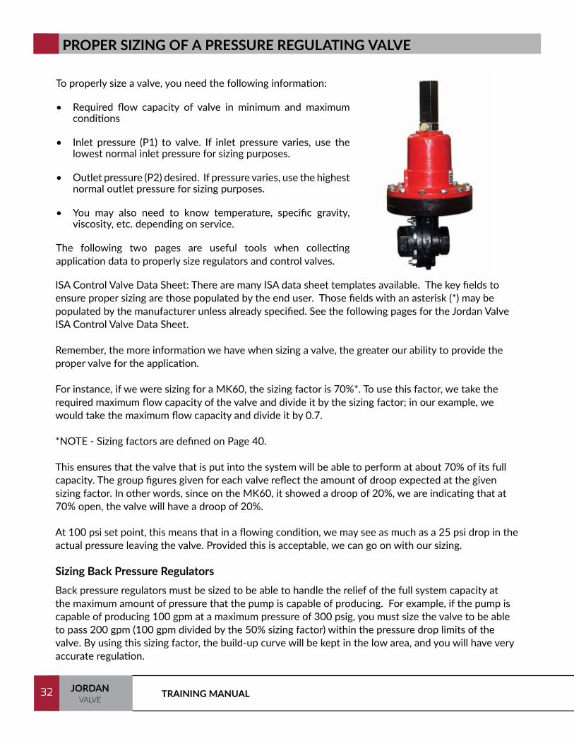
To properly size a valve, you need the following information:
• Required flow capacity of valve in minimum and maximum conditions
• Inlet pressure (P1) to valve. If inlet pressure varies, use the lowest normal inlet pressure for sizing purposes.
• Outlet pressure (P2) desired. If pressure varies, use the highest normal outlet pressure for sizing purposes.
• You may also need to know temperature, specific gravity, viscosity, etc. depending on service.
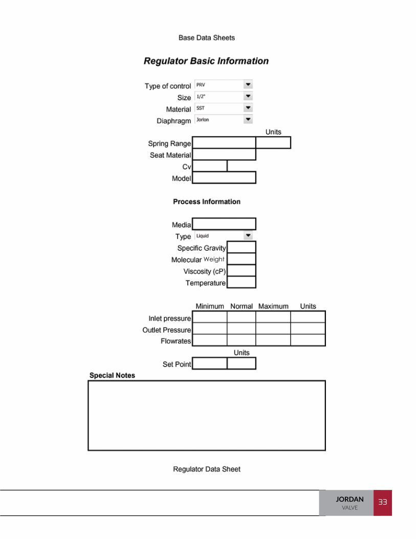
The following two pages are useful tools when collecting application data to properly size regulators and control valves.
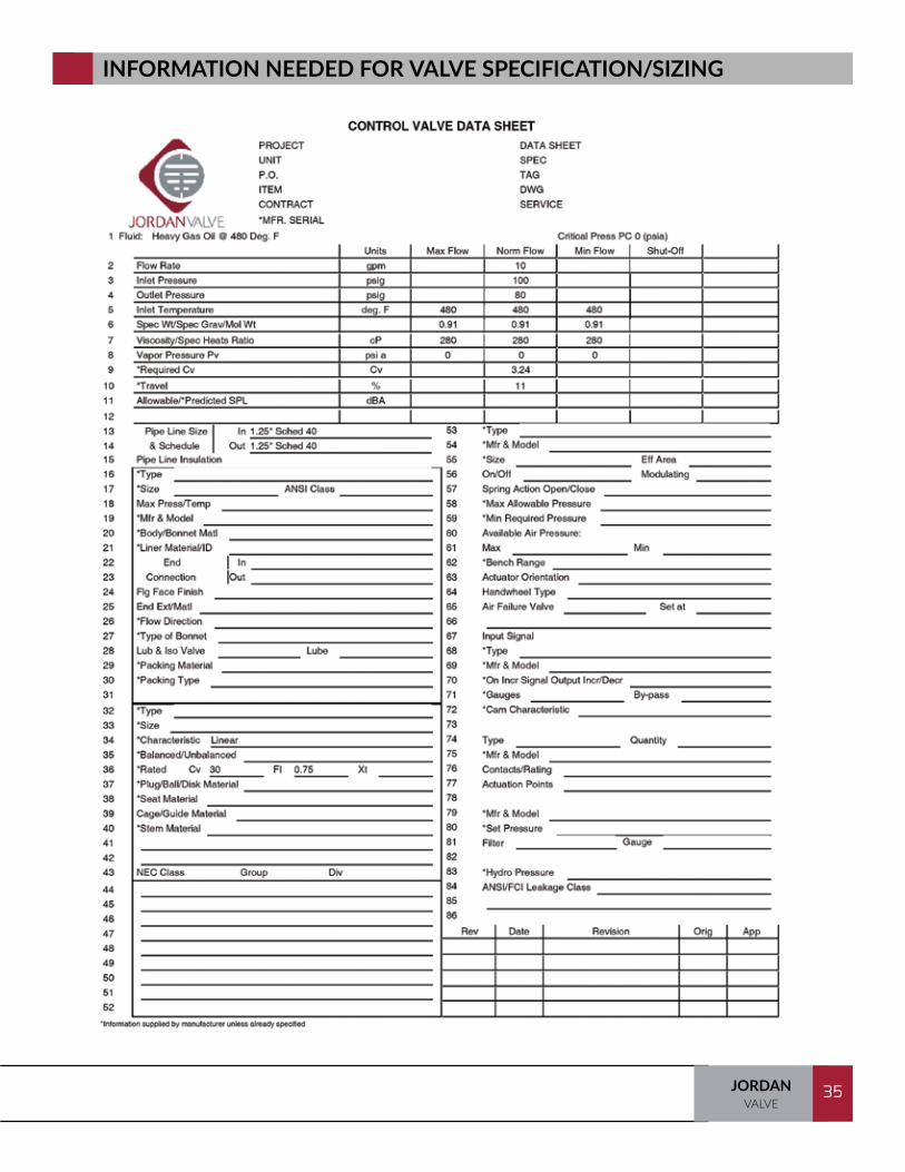
ISA Control Valve Data Sheet: There are many ISA data sheet templates available. The key fields to ensure proper sizing are those populated by the end user. Those fields with an asterisk (*) may be populated by the manufacturer unless already specified. See the following pages for the Jordan Valve ISA Control Valve Data Sheet.
Remember, the more information we have when sizing a valve, the greater our ability to provide the proper valve for the application.
For instance, if we were sizing for a MK60, the sizing factor is 70%*. To use this factor, we take the required maximum flow capacity of the valve and divide it by the sizing factor; in our example, we would take the maximum flow capacity and divide it by 0.7.
*NOTE - Sizing factors are defined on Page 40.
This ensures that the valve that is put into the system will be able to perform at about 70% of its full capacity. The group figures given for each valve reflect the amount of droop expected at the given sizing factor. In other words, since on the MK60, it showed a droop of 20%, we are indicating that at 70% open, the valve will have a droop of 20%.
At 100 psi set point, this means that in a flowing condition, we may see as much as a 25 psi drop in the actual pressure leaving the valve. Provided this is acceptable, we can go on with our sizing.
Sizing Back Pressure Regulators Back pressure regulators must be sized to be able to handle the relief of the full system capacity at the maximum amount of pressure that the pump is capable of producing. For example, if the pump is capable of producing 100 gpm at a maximum pressure of 300 psig, you must size the valve to be able to pass 200 gpm (100 gpm divided by the 50% sizing factor) within the pressure drop limits of the valve. By using this sizing factor, the build-up curve will be kept in the low area, and you will have very accurate regulation.
33JORDANVALVE
33
Weight

TRAINING MANUAL34 JORDANVALVE
34
Weight
35JORDANVALVE
35
INFORMATION NEEDED FOR VALVE SPECIFICATION/SIZING

TRAINING MANUAL36 JORDANVALVE
36
Designed for engineers, the JVCV is a valve sizing program that has been developed to help you quickly and accurately determine the flow coefficient (Cv) of a valve so that you can choose the proper Jordan valve for your application. The program will warn if cavitation flow is present, whether you have flashing flow or not, and will calculate noise level per IEC (International Electrotechnical Commission) standards. The JVCV program is available in a downloadable or web based version.
The install requires admin permissions. It also asks for a reboot to automatically start the service but you can do it manually from the start menu:
Richards Industries -> ServiceJVCV -> Service Management, select Start Service. After a reboot or a manual start, you should be able to load the app in your browser with the Online JVCV link on your desktop from the start menu or a bookmark.Once started, the program will remain available via the links until you uninstall.
The JVCV program is easy to use and is equipped with many user friendly features.
First, start by clicking on Jordan Valve on the home page.
JVCV SIZING PROGRAM
37JORDANVALVE
37
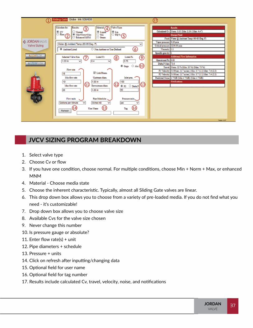
1. Select valve type2. Choose Cv or flow3. If you have one condition, choose normal. For multiple conditions, choose Min + Norm + Max, or enhanced
MNM4. Material - Choose media state5. Choose the inherent characteristic. Typically, almost all Sliding Gate valves are linear. 6. This drop down box allows you to choose from a variety of pre-loaded media. If you do not find what you
need - it's customizable!7. Drop down box allows you to choose valve size8. Available Cvs for the valve size chosen9. Never change this number 10. Is pressure gauge or absolute? 11. Enter flow rate(s) + unit12. Pipe diameters + schedule 13. Pressure + units14. Click on refresh after inputting/changing data15. Optional field for user name 16. Optional field for tag number 17. Results include calculated Cv, travel, velocity, noise, and notifications
JVCV SIZING PROGRAM BREAKDOWN
TRAINING MANUAL38 JORDANVALVE
38
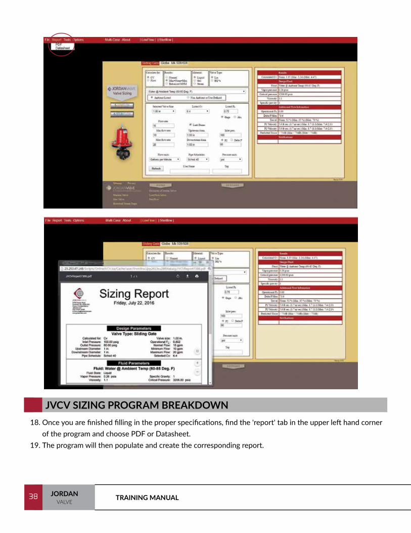
18. Once you are finished filling in the proper specifications, find the 'report' tab in the upper left hand corner of the program and choose PDF or Datasheet.
19. The program will then populate and create the corresponding report.
JVCV SIZING PROGRAM BREAKDOWN

39JORDANVALVE
39
The Calculated Cv in JVCV is the required Cv. When sizing for the following valve types, the figure should be divided by:
Back Pressure Regulators 0.5
Self Operated Regulators 0.7
Piloted Regulators 0.9
Dome Loaded Regulators 0.9
Piloted Back Pressure Regulator 0.9
Temperature Regulator 0.9
Diaphragm Operated Control Valve 0.9
Motor Operated Control Valve 0.9
SIZING FACTORS

TRAINING MANUAL40 JORDANVALVE
40
NOTES:

41JORDANVALVE
41
BACK PRESSURE REGULATORS
Back pressure regulators perform the opposite of pressure regulators. A back pressure regulator is normally closed while a pressure reducing valve is normally open. Secondly, the back pressure regulator controls upstream pressure (P1), while a PRV controls downstream pressure (P2). Other than that, the valves operate identically. In the normally closed position, upstream pressure is sensed underneath the diaphragm. As P1 increases above the set point, the pressure of the service overcomes the spring force and begins opening the valve. This bleeds off the pressure on the P1 side and maintains the constant upstream pressure.
Many people will refer to BPRVs as relief valves. Although they do perform a relieving function, they are not a snap acting safety relief device. Back pressure regulators regulate. This is an important point and important that BPRVs are not applied where a safety relief valve is required. These are not ASME coded devices.
Set Point Adjustment
Springs keep PRV in the normally open position
Downstream pressure is sensed beneath the diaphragm
Flow (P2)Flow (P1)
Controlled Variable
TRAINING MANUAL42 JORDANVALVE
42
Operation
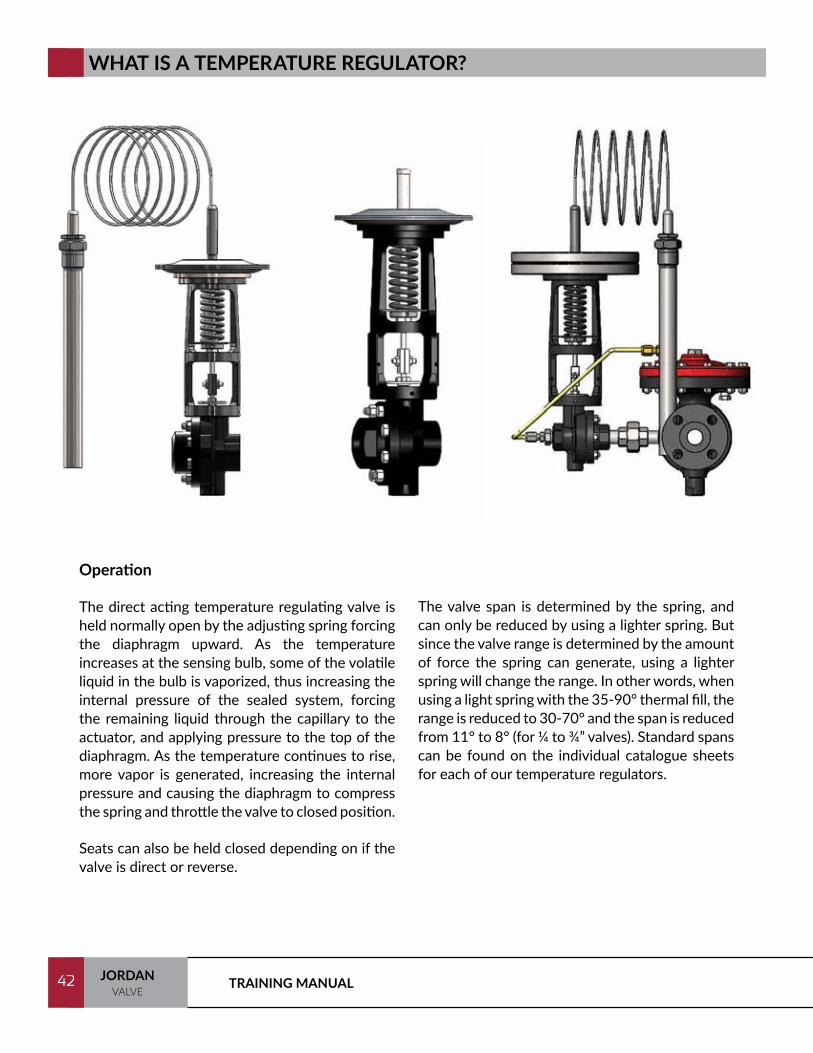
The direct acting temperature regulating valve is held normally open by the adjusting spring forcing the diaphragm upward. As the temperature increases at the sensing bulb, some of the volatile liquid in the bulb is vaporized, thus increasing the internal pressure of the sealed system, forcing the remaining liquid through the capillary to the actuator, and applying pressure to the top of the diaphragm. As the temperature continues to rise, more vapor is generated, increasing the internal pressure and causing the diaphragm to compress the spring and throttle the valve to closed position.
Seats can also be held closed depending on if the valve is direct or reverse.
The valve span is determined by the spring, and can only be reduced by using a lighter spring. But since the valve range is determined by the amount of force the spring can generate, using a lighter spring will change the range. In other words, when using a light spring with the 35-90° thermal fill, the range is reduced to 30-70° and the span is reduced from 11° to 8° (for ¼ to ¾” valves). Standard spans can be found on the individual catalogue sheets for each of our temperature regulators.
WHAT IS A TEMPERATURE REGULATOR?
43JORDANVALVE
43
DEFINITIONS
Bellows: Elastic vessels that can be compressed when pressure is applied to the outside of the vessel, or extended under vacuum. When the pressure or vacuum is released, the bellows will return to its original shape (provided the material has not been stressed past its yield strength).
Capillary: One of the components of a thermal system, the capillary is a thin, armor clad length of copper tubing connecting the sensing bulb to the actuator.
Finned Bulb: Made for sensing the temperature of the atmosphere. The “fins” increase the effective exposed surface, providing the necessary sensitivity.
Sensing Bulb: One of the components of a thermal system, the sensing bulb is positioned where the temperature is to be controlled.
Span: The amount of temperature change in the variable required to stroke the valve from full open to full closed.
SWA Actuator: The thermal system used by Jordan valve consists of three pieces of metal stamped and bonded together and heliarc welded around the outside. A bonded double stainless steel diaphragm is welded between the two stainless steel casings to provide an all metal seal.
Thermal Fill: A liquid housed in a thermal system that vaporizes and creates pressure within the sealed system.
Thermal System: A sealed system consisting of a sensing bulb, capillary, and actuator filled with a liquid that when heated, vaporizes and expands exerting force on the actuator diaphragm causing the valve to change position.
Thermal Well: Thermal wells (thermowells) are tubular fittings used to protect temperature sensors installed in industrial processes. A thermal well consists of a tube closed at one end and mounted in the process stream or vessel. A thermal well also allows for removal of the sensing bulb without shutting off the process stream or draining the vessel.

TRAINING MANUAL44 JORDANVALVE
44
UNDERSTANDING TEMPERATURE REGULATORS
Thermal Systems - There are various thermal systems available in the market today. The majority of the systems are Bellows Style. The vapor is housed in a metal accordion style bellows, which expands up and down according to the expansion and contraction of the internal fill. As the bellows expands, the spring is expanded or contracted to stroke the valve. Because of the metal fatigue involved in this type of expansion, they have a tendency to wear out rather quickly. Because of the long stroke of a globe style valve, the bellows must expand back and forth quite a distance. This leads to poor regulation in the form of higher spans and eventual failure.
The span of a temperature regulator is the amount of temperature change in the temperature being sensed required to stroke the valve from full open to full closed. The more narrow the span, the more accurate the temperature regulator.
The most accurate and reliable thermal system available is the SWA actuator. This actuator consists of three pieces of metal stamped and bonded together and then heliarc welded around the outside. A bonded double stainless steel diaphragm is welded between the two stainless steel casings to provide an all metal seal. There are no rubber parts in this actuator. There is no rubber to dry out, crack, or allow fill to leak out of the actuator itself.
Furthermore, this actuator, when combined with the short stroke of the Sliding Gate seat, enables the movement of the diaphragm to be just 1/3 the length of a bellows type. Thus, the metal fatigue involved with this diaphragm is considerably less than that of the bellows. Therefore, the reliability of this valve far exceeds anything else available in the market.

45JORDANVALVE
45
As mentioned previously, a temperature regulating valve is only as good as its actuator. That’s why so much time and effort has gone into the development of Jordan’s stainless steel actuator and, when combined with the Sliding Gate seat, provides you the finest temperature regulating valves today.
Stainless Steel Diaphragm Produced from AISI 347 stainless steel, the diaphragm is pre-formed to eliminate rupturing, which is a common failure of bellows type actuators caused by metal fatigue induced by constant movement.
Tamper-Proof The all welded construction of Jordan’s actuator prevents accidental breaking of the hermetic seal and the resultant loss of the system fill.
Liquid Vapor System To obtain the necessary force to positively position the valve seats, Jordan uses a liquid-vapor thermal system. A measured amount of “fill” goes into the system, filling all of the dome and capillary, and much of the sensing bulb. As the temperature at the bulb increases, the “fill” begins to boil, creating a vapor. As the vapor is generated, internal pressure increases and is transmitted through the capillary to the actuator. This causes the diaphragm to compress the spring and throttle the valve.
Sensitive Control Though relatively small, the actuator is extremely sensitive and reacts rapidly to very minor changes in temperature. The smaller size valves will fully stroke with a temperature change of only 10°.
THE SWA ACTUATOR
Stainless Steel Castings The upper and lower casings are die stamped from AISI 304 stainless steel, offering greater resistance to corrosive atmospheric conditions. This eliminates the possibility of leaks, which sometimes occur in porous castings.
Heliarc Welded Construction The top and bottom casings, and the diaphragms are heliarc welded around the circumference, fusing them into a solid bond. This eliminates the need for a gasket, a common source of leaks.
Maintenance-Free Jordan’s thermal actuators are completely assembled in one piece which is maintenance-free. Being hermetically sealed, the system is pre-set and requires no field adjustments.
Simple Replacement Secured to the yoke by only four screws, the actuator can be replaced in less than five minutes. Temperature control ranges can be changed by simply replacing the actuator even while the valve is still in the line.
TRAINING MANUAL46 JORDANVALVE
46
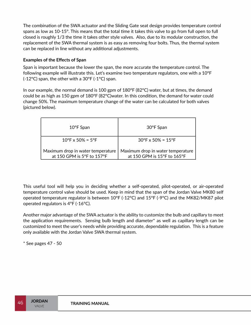
The combination of the SWA actuator and the Sliding Gate seat design provides temperature control spans as low as 10-15°. This means that the total time it takes this valve to go from full open to full closed is roughly 1/3 the time it takes other style valves. Also, due to its modular construction, the replacement of the SWA thermal system is as easy as removing four bolts. Thus, the thermal system can be replaced in line without any additional adjustments.
Examples of the Effects of Span Span is important because the lower the span, the more accurate the temperature control. The following example will illustrate this. Let’s examine two temperature regulators, one with a 10°F (-12°C) span, the other with a 30°F (-1°C) span.
In our example, the normal demand is 100 gpm of 180°F (82°C) water, but at times, the demand could be as high as 150 gpm of 180°F (82°C)water. In this condition, the demand for water could change 50%. The maximum temperature change of the water can be calculated for both valves (pictured below).
This useful tool will help you in deciding whether a self-operated, pilot-operated, or air-operated temperature control valve should be used. Keep in mind that the span of the Jordan Valve MK80 self operated temperature regulator is between 10°F (-12°C) and 15°F (-9°C) and the MK82/MK87 pilot operated regulators is 4°F (-16°C).
Another major advantage of the SWA actuator is the ability to customize the bulb and capillary to meet the application requirements. Sensing bulb length and diameter* as well as capillary length can be customized to meet the user’s needs while providing accurate, dependable regulation. This is a feature only available with the Jordan Valve SWA thermal system.
* See pages 47 - 50
10°F Span 30°F Span
10°F x 50% = 5°F
Maximum drop in water temperature at 150 GPM is 5°F to 157°F
30°F x 50% = 15°F
Maximum drop in water temperature at 150 GPM is 15°F to 165°F

47JORDANVALVE
47
STANDARD BULB SIZES
Jordan Valve offers a variety of standard options and sizes. Standard bulb sizes are shown in the chart below.
Nominal Bulb Size (Diameter x Length)
BulbType
for ranges beginning:
101°F (30°C) or above 100°F (38°C) or above
A & B
1" x 12" (standard)(2,5 cm x 30,5 cm)
1" x 14" (standard) (2,5 cm x 35,6 cm)
3/4" x 23" (optional)(1,9cm x 58,4 cm)
3/4" x 27" (optional)(1,9 cm x 68,6 cm)
C
1" x 12" (SST only)(2,5 cm x 30,5 cm)
1" x 14" (SST only)(2,5 cm x 35,6 cm)
1-1/8" x 14" (CU only)(2,9 cm x 35,6 cm)
1-1/8" x 14" (CU only)(2,9 cm x 35,6 cm)
D, E & F 1" x 12" (standard)(2,5 cm x 30,5 cm)
1" x 14" (standard)(2,5 cm x 35,6 cm)
TRAINING MANUAL48 JORDANVALVE
48
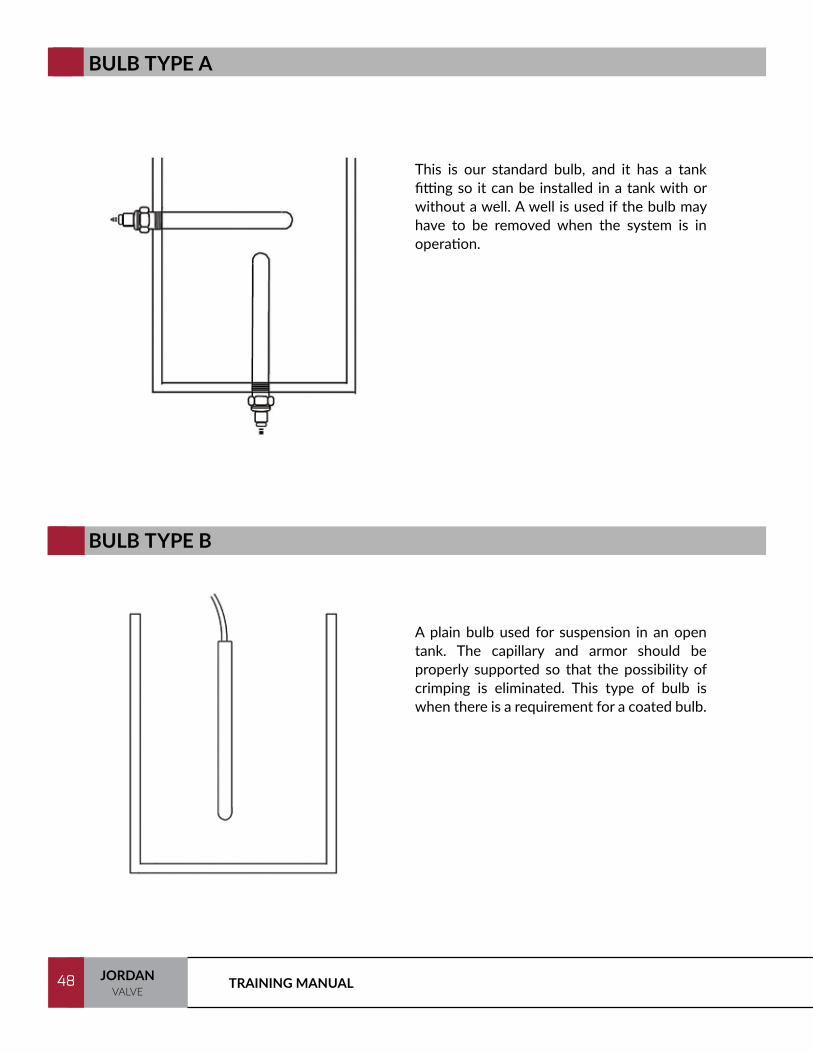
BULB TYPE A
This is our standard bulb, and it has a tank fitting so it can be installed in a tank with or without a well. A well is used if the bulb may have to be removed when the system is in operation.
BULB TYPE B
A plain bulb used for suspension in an open tank. The capillary and armor should be properly supported so that the possibility of crimping is eliminated. This type of bulb is when there is a requirement for a coated bulb.
49JORDANVALVE
49
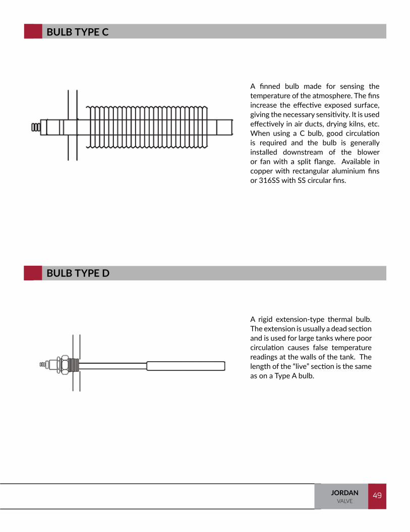
BULB TYPE C
A finned bulb made for sensing the temperature of the atmosphere. The fins increase the effective exposed surface, giving the necessary sensitivity. It is used effectively in air ducts, drying kilns, etc. When using a C bulb, good circulation is required and the bulb is generally installed downstream of the blower or fan with a split flange. Available in copper with rectangular aluminium fins or 316SS with SS circular fins.
BULB TYPE D
A rigid extension-type thermal bulb. The extension is usually a dead section and is used for large tanks where poor circulation causes false temperature readings at the walls of the tank. The length of the “live” section is the same as on a Type A bulb.

TRAINING MANUAL50 JORDANVALVE
50
BULB TYPE E
A pressure-tight extended bulb. If mounted horizontally, a well is needed for support. The length of the “live” section is the same as the Type A bulb.
BULB TYPE F
An extension-type bulb with an adjustable union that is not pressure-tight. This system is generally installed vertically where the added strength of the armor is desired. A well is required when mounting horizontally.
51JORDANVALVE
51
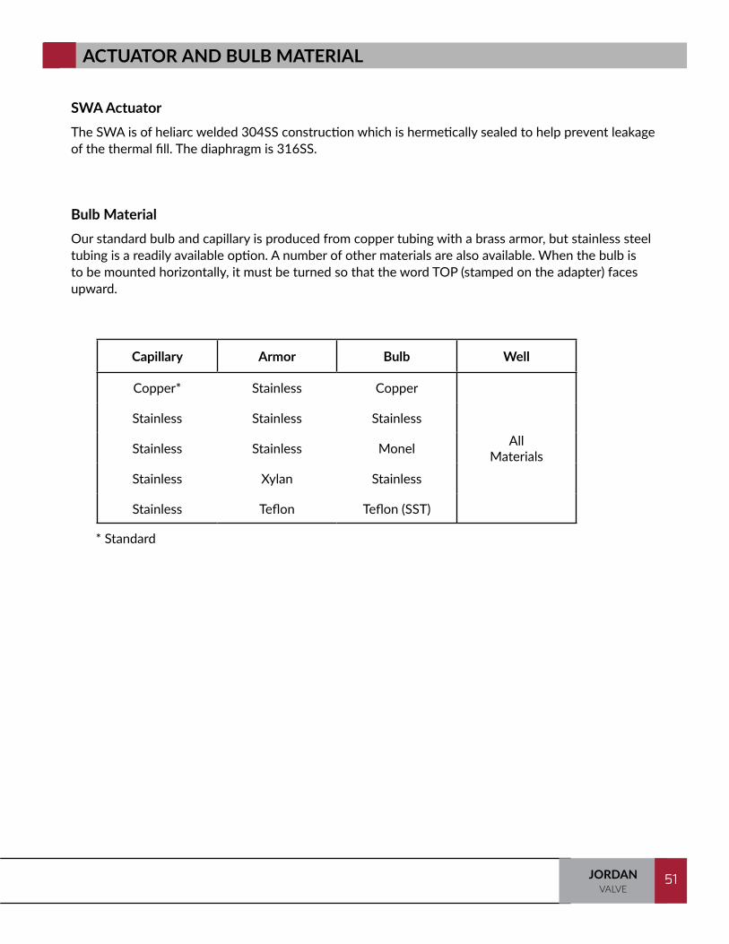
SWA Actuator The SWA is of heliarc welded 304SS construction which is hermetically sealed to help prevent leakage of the thermal fill. The diaphragm is 316SS.
Bulb Material Our standard bulb and capillary is produced from copper tubing with a brass armor, but stainless steel tubing is a readily available option. A number of other materials are also available. When the bulb is to be mounted horizontally, it must be turned so that the word TOP (stamped on the adapter) faces upward.
ACTUATOR AND BULB MATERIAL
* Standard
Capillary Armor Bulb Well
Copper* Stainless Copper
AllMaterials
Stainless Stainless Stainless
Stainless Stainless Monel
Stainless Xylan Stainless
Stainless Teflon Teflon (SST)
TRAINING MANUAL52 JORDANVALVE
52
TANK BLANKETING
What is Tank Blanketing?
Tank Blanketing, sometimes referred to as “padding”, is the process of filling the empty space of a liquid storage tank with an inert gas, most likely Nitrogen. Nitrogen is generally the blanketing gas of choice due to its inert properties, availability, and relatively low cost.
Why is Tank Blanketing Important?
Blanketing protects people, the environment, products, and equipment. If the media is combustible, blanketing removes the Oxygen required for combustion. Blanketing protects food and other substances from oxidation, contamination or evaporation. Vapor recovery prevents harmful vapors from escaping into the atmosphere. Reducing corrosion through oxidation helps maintain the integrity of the tank. Managing the tank pressure correctly limits the risk of implosion or explosion.
Who uses Tank Blanketing?
The bulk of tank blanketing applications are in the Chemical, Petrochemical and Oil & Gas Industries with a smaller percentage in the Food & Beverage, Pharma / Biopharm, Personal Care / Cosmetics and Semiconductor industries.
A variety of products are protected in the market segments listed above. Blanketed products include but are not limited to: adhesives, catalysts, chemicals, deionized water, fats and oils, flavors, foods, fragrances, fuels, industrial coatings, inks, juices, pharmaceuticals, photographic chemicals, sealants, soaps, solvents, volatile combustibles, and water for injection.
How do Blanketing Regulators Work?
Blanketing regulators, also referred to as padding or “make-up” regulators, are controlling the gas pressure inside the tank. The blanketing valve is typically mounted on top of a storage tank. The piping from the blanketing gas supply is connected to the valve inlet and the valve outlet is piped to the tank. In most cases, a sensing line runs from the tank to the valve’s sensing port.
When the regulator senses a decrease in the pressure, the valve opens to introduce more gas into the tank until the vapor pressure in the tank reaches the desired set point. When the pressure reaches or begins to exceed the set point, the valve moves to the closed position and pressure returns to the set point.
53JORDANVALVE
53
DEFINITIONS
API 2000: The American Petroleum Institute’s standard information regarding tank blanketing regulator selection.
De-pad Valves: Used in conjunction with a tank blanketing (padding) regulator, a de-pad valve is a back pressure regulator that vents gas from the tank to prevent damage from over pressurization. The regulator senses an increase in the blanket pressure and opens to relieve pressure in the tank to atmosphere or for reclamation.
External Pressure Registration: Pressure sensing is achieved through the use of an external sensing line located downstream for PRV and upstream for BPRV.
Internal Pressure Registration: Pressure sensing is achieved via a channel inside the valve body.
One-sided System: A tank blanketing system where only a padding valve is utilized.
Sensing Line: Also called the control line, this is attached to the valve actuator and / or pilot and the place on the tank where the pressure is to be controlled. This allows the valve to sense the pressure in the tank.
Tank Blanketing: Sometimes referred to as “padding”, the process of filling the empty space of a liquid storage tank with an inert gas, most likely Nitrogen
Tank Blanketing Regulator: Also called padding and “make-up” regulators. The regulator is controlling the pressure inside the tank. When the regulator senses a decrease in the blanket pressure, it opens to introduce more gas and moves to the close position when pressure returns to the set point.
Two-sided System: A padding valve and de-pad valve are both used on a tank. Both valves are controlling the pressure in the tank. The padding valve ensures there is enough pressure in the tank and the de-pad valve prevents over pressurization.

TRAINING MANUAL54 JORDANVALVE
54
SELF-OPERATED
There are several padding regulator choices available in the marketplace. Self operated blanketing regulators offer fast response, low initial cost and a simple design. Self operated regulators can use internal pressure registration which allows easier installation, or, an external sensing line that generally provides greater accuracy.
Self operated regulators are very sensitive and can achieve low set points due to their large diaphragms and light spring. For higher inlet pressures and flows, balanced plug and double seated versions are available.
360° body orientation. Valve can be installed in any position and easily repositioned while inline
Soft elastomer plug provides tight shutoff
Aspirator is designed and situated to optimise the boost effect and improve performance - no sensing line required
Large elastomer diaphragms and a variety of spring ranges provide excellent sensitivity and accurate regulation
Lever amplifies diaphragm forces for tighter shutoff

55JORDANVALVE
55
EXTERNALLY PILOTED
Pilot operated blanketing valves offer higher flows, greater accuracy, and extremely fast lock-up. Blanketing valves can be internally or externally piloted.
Globe style conditioning regulator drops the inlet pressure to 150 to 25 psig to feed the pilot regulator
Main valve body and actuator handle high inlet pressure and high flows
The pilot valve provides accurate controls and fast lockup
TRAINING MANUAL56 JORDANVALVE
56
INTERNALLY PILOTED
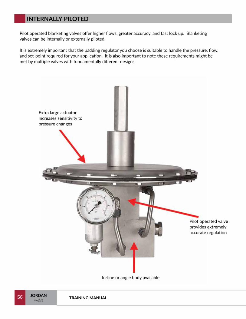
Pilot operated blanketing valves offer higher flows, greater accuracy, and fast lock up. Blanketing valves can be internally or externally piloted.
It is extremely important that the padding regulator you choose is suitable to handle the pressure, flow, and set-point required for your application. It is also important to note these requirements might be met by multiple valves with fundamentally different designs.
Extra large actuator increases sensitivity to pressure changes
In-line or angle body available
Pilot operated valve provides extremely accurate regulation

57JORDANVALVE
57
WHAT IS A CONTROL VALVE?
Control valves are valves used to control conditions such as flow, pressure, temperature, and level by fully or partially opening or closing in response to signals received from controllers that compare a "setpoint" to a "process variable" whose value is provided by sensors that monitor changes in such conditions.[1] Control Valve is also termed as the Final Control Element.
A control valve is the most widely used type of final control element of a control loop, and is used to amplify low level power from a controller to higher level power required to control the flowing fluid.A control loop consists of three major elements:• A sensing element• A controlling element• A final control element
A sensing element measures the process variable which is being controlled, and then sends the output to the controlling instrument. Among the variables that can be measured:• Pressure• Flow• Level• Temperature• pH
1 Bela G. Liptak (Editor) (2003). Instrument Engineers' Handbook (4th ed.). CRC Press.

TRAINING MANUAL58 JORDANVALVE
58
DEFINITIONS
Valve Actuator: The mechanism used to open and close a valve. In a control valve, the actuator repositions the disc or plug of a control valve to correct the error.
Control Instrument: Calculates the error (difference in signal from sensing element and the desired set-point) and sends corrective signal to final control element.
Control Loop: A process management system designed to maintain a process variable at a desired set point. Each step in the loop works in conjunction with the others to manage the system.
Equal Percentage: Equal increments of valve travel produce equal changes in existing flow.
Final Control Element: The control valve varies the flow to change the controlled variable to the required set-point.
Flow Characteristic: The relationship between flow through the valve and the valve stem (plug) position as the valve is stroked from 0 to 100% of the rated travel.
Flow Curve: The percentage of valve opening plotted against valve stem position.
Inherent Characteristic: The flow characteristic of the valve alone as a constant pressure drop is maintained across the valve.
Installed Characteristic: The flow characteristic of the valve installed in the system where the pressure drop across the valve varies as dictated by variations in flow and other conditions of the system. This is unique for each valve installation.
Linear: Flow rate is directly proportional to valve travel.
Quick Opening: A flow characteristic where maximum flow change is achieved with minimal valve travel
59JORDANVALVE
59
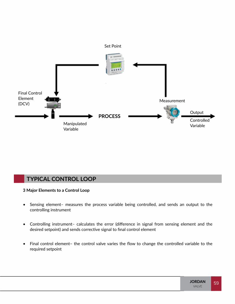
TYPICAL CONTROL LOOP
3 Major Elements to a Control Loop
• Sensing element– measures the process variable being controlled, and sends an output to the controlling instrument
• Controlling instrument– calculates the error (difference in signal from sensing element and the desired setpoint) and sends corrective signal to final control element
• Final control element– the control valve varies the flow to change the controlled variable to the
required setpoint
Set Point
Final Control Element (DCV)
Manipulated Variable
Measurement
Output
Controlled Variable
PROCESS
TRAINING MANUAL60 JORDANVALVE
60
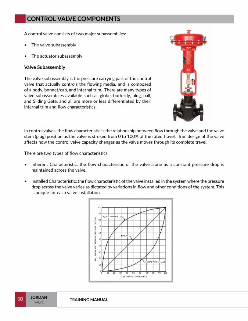
CONTROL VALVE COMPONENTS
A control valve consists of two major subassemblies:
• The valve subassembly
• The actuator subassembly
Valve Subassembly
The valve subassembly is the pressure carrying part of the control valve that actually controls the flowing media, and is composed of a body, bonnet/cap, and internal trim. There are many types of valve subassemblies available such as globe, butterfly, plug, ball, and Sliding Gate, and all are more or less differentiated by their internal trim and flow characteristics.
In control valves, the flow characteristic is the relationship between flow through the valve and the valve stem (plug) position as the valve is stroked from 0 to 100% of the rated travel. Trim design of the valve affects how the control valve capacity changes as the valve moves through its complete travel.
There are two types of flow characteristics:
• Inherent Characteristic: the flow characteristic of the valve alone as a constant pressure drop is maintained across the valve.
• Installed Characteristic: the flow characteristic of the valve installed in the system where the pressure drop across the valve varies as dictated by variations in flow and other conditions of the system. This is unique for each valve installation.
QUICK OPENING
LINEAR
EQUAL PERCENTAGE
FULL VALVE STEM TRAVEL %
FULL
FLO
W A
T CO
NST
AN
T PR
ESSU
RE D
ROP
%
00
10 20 30 40 50 60 70 80 90 100
10
20
30
40
50
60
70
80
90
100
61JORDANVALVE
61
The most common characteristics are shown on the previous page. The curves shown are representative and typical of those available from many valve manufacturers.
These curves are based on constant pressure drop across the valve and are called inherent flow characteristics. The majority of control applications are valves with linear, equal-percentage, or modified-flow characteristics.
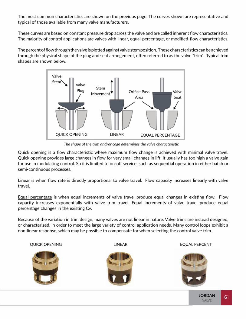
The percent of flow through the valve is plotted against valve stem position. These characteristics can be achieved through the physical shape of the plug and seat arrangement, often referred to as the valve "trim". Typical trim shapes are shown below.
Quick opening is a flow characteristic where maximum flow change is achieved with minimal valve travel. Quick opening provides large changes in flow for very small changes in lift. It usually has too high a valve gain for use in modulating control. So it is limited to on-off service, such as sequential operation in either batch or semi-continuous processes.
Linear is when flow rate is directly proportional to valve travel. Flow capacity increases linearly with valve travel.
Equal percentage is when equal increments of valve travel produce equal changes in existing flow. Flow capacity increases exponentially with valve trim travel. Equal increments of valve travel produce equal percentage changes in the existing Cv.
Because of the variation in trim design, many valves are not linear in nature. Valve trims are instead designed, or characterized, in order to meet the large variety of control application needs. Many control loops exhibit a non-linear response, which may be possible to compensate for when selecting the control valve trim.
QUICK OPENING LINEAR EQUAL PERCENT
The shape of the trim and/or cage determines the valve characteristic
Valve Stem
Valve Plug Stem
Movement Orifice Pass Area
Valve Seat
QUICK OPENING LINEAR EQUAL PERCENTAGE

TRAINING MANUAL62 JORDANVALVE
62
INHERENT AND INSTALLED FLOW CHARACTERISTICS
It is important to select a control valve with the correct flow characteristic. Control valves have two flow characteristics: inherent flow characteristic and installed flow characteristic.Inherent Control Valve Flow Characteristics– These curves are based on constant pressure drop across the valve. The majority of control applications are with valves with linear, equal-percentage, or modified-flow characteristics (See figure 1).
NOTE: These flow characteristic curves were developed after extensive research and comparisons of the performance curves of many different valve manufacturers. These characteristic curves are smoothed, best fit representations of an average of those manufacturers' curves[1].
The inherent characteristic of a valve is the characteristic published by the manufacturer, based on tests performed in a system where great care is taken to ensure that the pressure drop across the test valve is held constant at all valve openings and flow rates. The inherent characteristic, therefore, represents the relationship between valve flow capacity and valve opening when there are no system effects involved.
Different valve designs have different inherent characteristics. For example:• Jordan Valve Sliding Gate Valves – Linear• Globe valves – Equal percentage, linear or quick opening• High performance butterfly valves – Modified linear• Ball valve – Equal percentage
Installed Control Valve Flow Characteristics – When valves are installed with pumps, piping and fittings, and other process equipment, the pressure drop across the valve will vary as the plug moves through its travel. When the actual flow in a system is plotted against valve opening, the curve is called the Installed Flow Characteristic.
In most applications, when the valve opens, and the resistance due to fluids flow decreases the pressure drop across the valve. This moves the inherent characteristic.
FIGURE 1
63JORDANVALVE
63
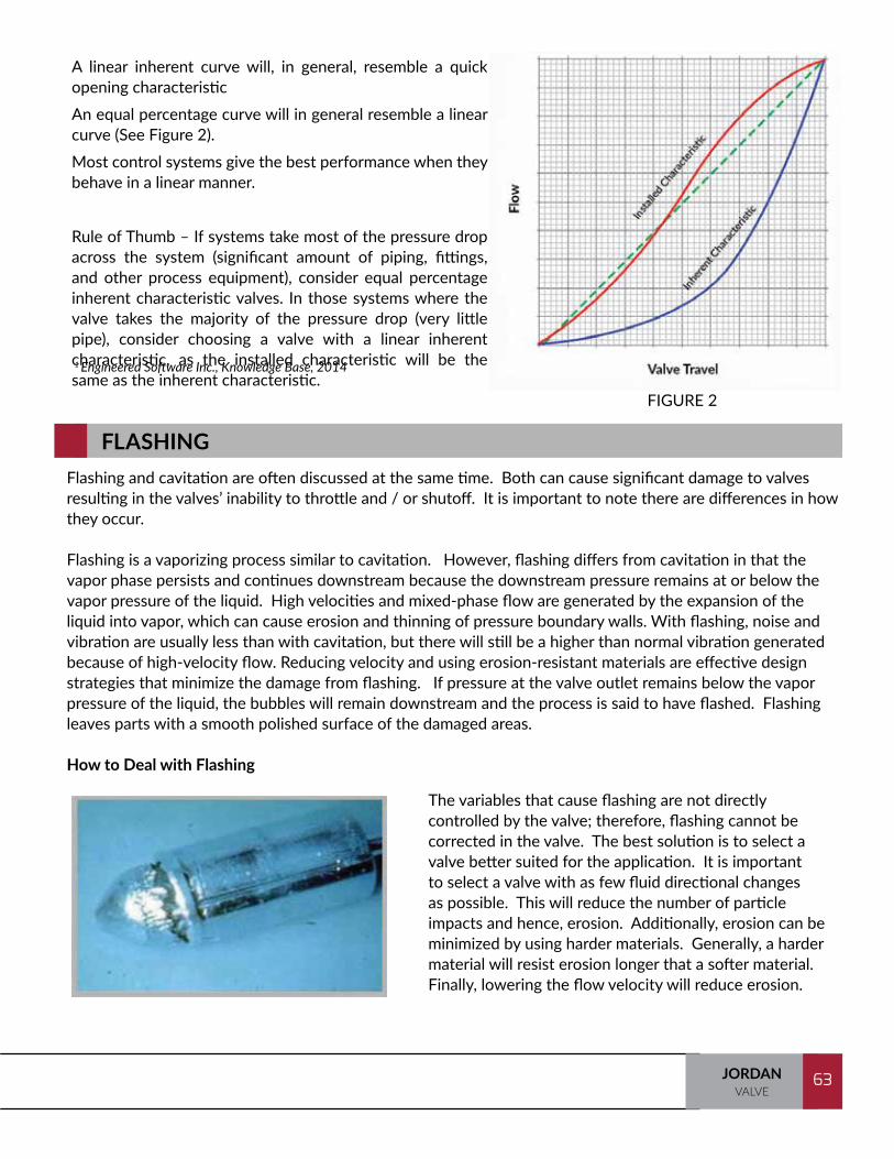
A linear inherent curve will, in general, resemble a quick opening characteristicAn equal percentage curve will in general resemble a linear curve (See Figure 2).Most control systems give the best performance when they behave in a linear manner.
Rule of Thumb – If systems take most of the pressure drop across the system (significant amount of piping, fittings, and other process equipment), consider equal percentage inherent characteristic valves. In those systems where the valve takes the majority of the pressure drop (very little pipe), consider choosing a valve with a linear inherent characteristic, as the installed characteristic will be the same as the inherent characteristic.1 Engineered Software Inc., Knowledge Base, 2014
FIGURE 2
FLASHING Flashing and cavitation are often discussed at the same time. Both can cause significant damage to valves resulting in the valves’ inability to throttle and / or shutoff. It is important to note there are differences in how they occur.
Flashing is a vaporizing process similar to cavitation. However, flashing differs from cavitation in that the vapor phase persists and continues downstream because the downstream pressure remains at or below the vapor pressure of the liquid. High velocities and mixed-phase flow are generated by the expansion of the liquid into vapor, which can cause erosion and thinning of pressure boundary walls. With flashing, noise and vibration are usually less than with cavitation, but there will still be a higher than normal vibration generated because of high-velocity flow. Reducing velocity and using erosion-resistant materials are effective design strategies that minimize the damage from flashing. If pressure at the valve outlet remains below the vapor pressure of the liquid, the bubbles will remain downstream and the process is said to have flashed. Flashing leaves parts with a smooth polished surface of the damaged areas.
How to Deal with Flashing
The variables that cause flashing are not directly controlled by the valve; therefore, flashing cannot be corrected in the valve. The best solution is to select a valve better suited for the application. It is important to select a valve with as few fluid directional changes as possible. This will reduce the number of particle impacts and hence, erosion. Additionally, erosion can be minimized by using harder materials. Generally, a harder material will resist erosion longer that a softer material. Finally, lowering the flow velocity will reduce erosion.

TRAINING MANUAL64 JORDANVALVE
64
Cavitation, simply defined, is a localized gaseous condition formed in a liquid stream. Cavitation occurs when the pressure of the flowing media is reduced to a value less than the vapor pressure. This pressure reduction at the vena contracta (the point of highest velocity and lowest pressure) allows the liquid to form bubbles. As the flow passes the vena contracta, it begins to slow down and the pressure recovers causing the bubbles to implode - resulting in shock waves. Each of these shock waves erodes a small amount of material from the valve’s interior. While each implosion removes only a minute amount of material, the cumulative effect is significant. In fact, severe pitting can destroy the valves' interior and associated piping in a brief time.
CAVITATION
There are a few options available to help reduce or eliminate the problems caused by cavitation.
1. Reduce the Delta P to a value below the onset of cavitation. Raise the outlet pressure so the vena contracta pressure does not fall below the vapor pressure.
2. Use cavitation control trim. Cavitation control trim induces cavitation in a controlled manner so that the pressure recovery and the resulting implosions take place in an area where they will not damage the trim.
3. Minimize damage by using harder materials. This solution is buying time. Eventually, cavitation will still damage the valve.
It is never wise to ignore cavitating flows. In order to ensure long life and trouble-free operation, it is necessary to take whatever steps are necessary to eliminate cavitation.
CAVITATION CONTROL TRIM
DAMAGE CAUSED BY CAVITATION

65JORDANVALVE
65
Three significant issues to watch for when selecting a control valve are Cavitation, Flashing, and Noise.
Noise and velocity go together. Since noise is caused by vibration, the source of much of the noise in piping systems can be attributed to regulators and control valves. These components are keys to low noise systems.
Pragmatic approach. Because noise characteristics are so important to the proper application of control valves, Jordan Valve invested in the fundamental studies necessary to derive workable production methods. This research was conducted at the University of Cincinnati, by Mechanical Engineering Department personnel, using equipment and methods generally accepted by industry and technical associations.
There are three major causes of valve noise: cavitation, which in the case of liquids may occur at high pressure drops; mechanical vibration of valve parts; and aerodynamic turbulence.
Cavitation - This phenomenon occurs only when transporting liquids. The increase in velocity of the liquid as it flows through the valve causes the static pressure to decrease. Bubbles will form if the pressure drops below the vapor pressure of the liquid. At some point within the exiting portion of the valve, the liquid velocity will decrease, causing the static pressure to increase above the vapor pressure, resulting in a sudden collapse of the bubbles. This process produces sound similar to gravel rattling in the flow system. Noise and valve damage as a result of cavitation can be avoided by selecting appropriate limits to the service conditions.
Mechanical Vibration - This is caused by random pressure fluctuations within the valve body, and by fluid impingement upon movable or flexible parts of the valve. It causes the particular component to vibrate at its natural frequency. High stress concentrations are created which ultimately may result in fatigue failure of the part.
Aerodynamic Noise - While cavitation and mechanical vibration are noticeable sources of noise, experience has shown that aerodynamic noise is by far the most prevalent cause of total valve noise.
Aerodynamic noise is a result of turbulent flow in steam, air, and other gases. Common origins of aerodynamic noise are at obstructions in the flow path, rapid expansion of the flow stream causing deceleration of the high velocity gas exiting from the valve, and sharp turns or bends of the fluid stream. The noise originates from the highly turbulent regions that have high rates of fluid deceleration. These motions or waves consist of successive compression and rarefaction[1] gas layers that travel away from the disturbance. A major portion of the sound is radiated downstream from the valve into the open pipe causing it to vibrate, and in turn transmits the noise to the surrounding area. Upstream propagation can occur, but usually is inhibited by the velocity of the fluid as well as the physical blockage of the sound field due to the flow constriction. The velocity of the fluid stream and the extent of the turbulent region control the noise level of the disturbance.
In summary: the factors that control noise level are velocity, flow rate, upstream pressure, valve pressure drop, geometry of the flow path, as well as the fluid physical properties.
With the unique and simple design of the Jordan Sliding Gate Valve, a large amount of valve-induced noise is eliminated.
NOISE

TRAINING MANUAL66 JORDANVALVE
66
The straight-through flow, which is an important design feature in the standard Jordan Sliding Gate valve, minimizes flow turbulence which is a major cause of aerodynamic noise. As aerodynamic noise tends to be the most common cause of valve noise encountered, this will drastically improve many applications.
Valve noise is further reduced in Sliding Gate Valves as the seat design drastically minimizes potential for mechanical vibrations in the valve. As the gate and plate remain in constant contact at all times, potential for vibrations and wear of these seating parts is significantly reduced or eliminated.
Compare the following examples in these specific applications. On Chart #1, saturated steam is run through a globe style valve in a system. The inlet pressure is 10 bar with an outlet pressure of 5 bar. The flow rate is 1500 kg per hour, with a calculated Cv of 13.6. When calculated for noise output, the noise emitted by the globe style valve measures more than 81 dB when the valve is operating at 45.3% valve capacity (noise is measured three feet away from the valve).
Compare Chart #1 to Chart #2. Chart #2 displays the noise production of a Sliding Gate valve using the same operating parameters that were present in the globe-style valve application of Chart #1. In Chart #2, the Cv is 17.94, and the noise levels measured three feet from the valve are 74 dB when the valve is operating at 59.8% of valve capacity (a higher capacity than the globe style valve).
To help put those numbers into perspective consider this: The average whisper or rustle of leaves measures 20 decibels. Average conversational speech measures 50-70 decibels at 1 meter away. The average alarm clock at 2 feet away measures 80 decibels. Lawn mowers range between 90 and 105 decibels. As you can see, an increase of a seemingly small number of decibels can make a significant difference in noise level.
So, in the valve example demonstrated in charts #1 and #2, the difference between the Sliding Gate valve and a globe style valve would be similar to the difference between conversational speech and an alarm clock, or a single running car compared to heavy traffic.
Remember, OSHA maintains very specific standards concerning noise production. Due to their design, selecting Sliding Gate valves will help you select more valves that will fall within these OSHA acceptable noise parameters.
1 Rarefaction is the reduction of density, the opposite of compression.

67JORDANVALVE
67
ACTUATOR SUBASSEMBLY
As mentioned earlier, the second component of a control valve is the actuator subassembly. This subassembly amplifies the low power error signal from the controller into a signal with sufficient power to reposition the disc or plug in order to correct the error. The actuator must have sufficient gain (amplification) to generate, from the error signal, a force large enough to reposition the valve disc or plug and overcome the forces in the valve:
• Packing friction
• Seat friction (in Sliding Gate valves)
• Force due to pressure drop across plug in globe valve
• Weight of parts

TRAINING MANUAL68 JORDANVALVE
68
What is Hysteresis?
Hysteresis is the variation of stem position at a specific control pressure at increasing control signal compared to decreasing control signal. It is usually expressed as a percent of total travel, and is caused by packing friction and seat friction.
What is Dead Band?
Dead band is the change in the control signal required to initiate valve stem movement. It is usually expressed as a percent of total control signal, and is caused by static friction (“stick-slip”), weight of parts, and the dynamic forces in the seats caused by flowing media.
Types of Actuators
There are a variety of actuators on the market:
• Pneumatically operated diaphragm actuators
• Piston (cylinder) actuators
• Electro-hydraulic electro-pneumatic actuators
• High performance servo actuators
• Electro-mechanical actuators
Jordan valve provides pneumatically operated diaphragm actuators, piston actuators, and electromechanical (motor) actuators.

69JORDANVALVE
69
WAYS TO COMBAT HYSTERESIS AND DEAD BAND
Use of a Larger ActuatorBecause sensitivity is affected by diaphragm area, the use of a larger actuator will result in more accurate control.
Jordan’s standard actuator is our 35M multi-spring actuator which features a 40 square inch effective diaphragm area. For greater control and higher pressure drops, our larger 55M and 85M actuators are available. All of our multiple spring actuators are completely enclosed to offer protection from the environment, and are designed to give the proper actuator range.
Pneumatic PositionerA positioner is a device used to accurately position the control valve disc or plug. It reduces actuator dead band and hysteresis while maintaining the valve stem in the proper position relative to the error signal from the controller.
A positioner should be used when:• Very accurate control is required• You need to increase the force output of the actuator
(for a higher pressure out of the positioner than the error signal)
• You need higher pressure drop capabilities across the valve
• Handling very viscous fluids• The valve must respond to very small error signal• You wish to increase the valve response (the
valve moves quicker due to higher capacity of the positioner)
• You desire characterized flow
Other Accessories• Limit switches: sense valve position (open or closed)• Switching valve: for split range operation such as
3-9/9-15 psi. For use with two valves in parallel – one 3-9 psi, the other 9-15 psi.
• I to P converter: to operate a pneumatic valve from an electronic signal such as 4-20 mA.
• Handwheel: to manually operate valve – used for back-up

TRAINING MANUAL70 JORDANVALVE
70
WHY REDUCE PRESSURE?
Pressure is reduced in an attempt to get the most available heat out of each pound of steam fed into the heat exchange surfaces. As the pressure of the steam decreases, the latent heat of evaporation increases. In general, as we lower the pressure of the steam in the heat exchanger, we get a greater percentage of the available heat out of it.
Then why don’t we operate the boiler at the lowest pressure required in the heat exchanger? This can be done if the heat exchangers are in close proximity to the boiler. But the situation changes if the steam has to be transmitted for any distance.
Consider the commonly found combination of 5 psig steam for a heat exchanger and 125 psig steam in transmission main. As the steam pressure increases, its total heat per pound increases, and the volume occupied by each pound of steam decreases. Comparing the two characteristics at 5 psig and at 125 psig, we can readily calculate that it would take approximately seven times the cross-sectional area of steam main to transmit 5 psig steam as it does to transmit it at 125 psig for equal weights. It would also take a larger boiler to generate the steam at 5 psig.
Thus…pressure is reduced because the increased cost in steam piping and fittings could be tremendous if we transmitted low pressure steam for any appreciable distance.

71JORDANVALVE
71
We can reduce steam pressure by simply throttling it through a manually adjusted valve or an automatic pressure regulating valve. The principle is the same in either case: a rapid reduction in pressure due to passage of the steam through a restriction line, with a resultant expansion in the downstream side of the valve.
As an example, we’ll continue our application from the previous page, and reduce 125 psig steam in the transmission main down to 5 psig for use in a heat exchanger, with an automatic reducing valve. It’s easy to see that there has been no appreciable loss in heat from the upstream side to the downstream side of the valve; therefore, the total heat in each pound of steam has not changed in the process.
As the pressure drops, the total heat per pound of saturated steam decreases, so where has the difference in heat content gone? It is still there in the steam. If the 125 psig steam was wet, containing entrained moisture, the difference in total heat will have a drying effect on that moisture, as the heat will evaporate the droplets of moisture into wet saturated steam.
Now, suppose the 125 psig steam was dry, but saturated before it entered the reducing valve. The result is superheated steam at 5 psig and about 305°F, as the excess heat has gone into raising the temperature of the steam.
However, very seldom will today’s industrial boiler in the average plant produce steam that has less than 4% moisture. The trend is toward higher steaming rates which produce very wet steam in most cases, with a considerable amount of entrained moisture. Consequently, there is a very low probability that the average industrial plant is producing superheated steam in the pressure reducing valves in its steam system. If any is being produced, the effect may actually be beneficial.
A little logical thinking on the method of passing the steam through a throttling valve will produce the conclusion that it must be an inefficient way of doing it. If steam is going to be expanded from 125 psig to 5 psig, there must be a tremendous waste of energy. Why not put it to use in the process?
This is being done in a large number of industrial plants where the steam requirements run into the thousands of pounds per hour. In such cases, it is not unusual to find that steam is being produced in the boiler at pressures as high as 400 psig, and is being used to generate at least part of the plant’s electrical energy in a steam turbine generator. It is exhausted at low pressure and then used in the plant’s process work. This system is also quite common in refineries and large chemical plant complexes, as well as many of the large automobile plants.
The same method is also quite prevalent in countries or areas where fuel costs are high, such as England. There are many ingenious methods devised in some such areas to get the most use out of each pound of steam generated. In the United States, we find that maintenance and operating costs are relatively higher than fuel costs, so simplicity is the rule in medium to smaller plants. This calls for the basic pressure reducing valve in place of a steam turbine driver or other such method of reducing the steam pressure.
When steam is expanded in a turbine, engine driver, or similar apparatus, the resultant low pressure steam is very wet, as the expansion accompanied with expenditure of useful work produces a condensing effect on the steam instead of the drying effect experienced with the reducing valve. Therefore, a pressure reducing valve is the most effective way to reduce steam pressure.
HOW TO REDUCE STEAM PRESSURE

TRAINING MANUAL72 JORDANVALVE
72
JORDAN VALVE APPLICATION MATRIX
Jordan Valve Type
APPLICATION
MK33 X XMK37 X X XMK39 X X XMK40/MK46 XMK44 XMK50MK501/MK502/MK51 X X XMK5108 XMK52 X X XMK53/54 X X XMK55 X XMK56 X X XMK57 X X XMK58A/MK58FT X X X X XMK508 X X X XMK518 X X X XMK60/MK601/MK602/MK61 X XMK6127MK62 X XMK63/MK64 X X XMK65 X XMK66 X XMK67 X XMK68G X X X XMK68HP X X X XMK608 X X XMK608BP X X XMK608DS X X XMK608IS X X XMK627 XMK630 XMK660 X XMK686 X XMK687 X X XMK688 X X XMK695X / MK695 X XMK70/MK701/MK702/MK711/MK707 X X XMK74 X X XMK75 X X XMK76 X X XMK78 X X XMK79/MK79MX X X XMK82 X XMK85 X XMK86 X XMK87 X XMK89/MK89MX X XMK2000 X X XMK D/MK DA X X XMK ED/MK ET/MK EZ X X X XMK HPX X X X X
Stea
m
Air
Arg
on
Atom
izin
g
Back
Pr
essu
re/B
ypas
s
Boile
r Fee
d W
ater
Buta
ne
Carb
on D
ioxi
de
Cont
rol V
alve

73JORDANVALVE
73
XX XX X X
X XX
X X X X X XX
X XX
X X XX X X
X X X X X X X XX X XX X X
X X X X XX XX
X X XX
X X X XX X X X
X X X X X X X X XX X X X X X X X X
X X X XX X X XX X X XX X X XX XX X
X X X X X XX X X X X X X X XX X X X X X X X X XX X X X X X X X X X
X X
XX X X X X X
X X X X XX X X X X X
XXXXX
X X
X X XX X X X X X XX X X X X X
Diff
eren
tial
Elec
tric
Mot
or O
p
Floa
t &
Leve
r Con
trol
Fuel
Gas
Fuel
Oil
Burn
er
Cont
rol
Gas
olin
e
Indu
stria
l Gas
es
Kero
sene
Lube
Oil
Mix
ing/
D
iver
ting
Mot
or O
il
Nat
ural
Gas
Nitr
ogen
Prop
ane
Pres
sure
Re
duci
ng
Tank
Bla
nketi
ng
Tem
pera
ture
Co
ntro
l
Vacu
um
Wat
er
Zero
Fug
itive
Em
issio
ns
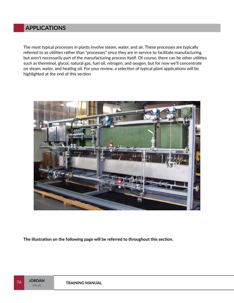
TRAINING MANUAL74 JORDANVALVE
74
The most typical processes in plants involve steam, water, and air. These processes are typically referred to as utilities rather than “processes” since they are in service to facilitate manufacturing, but aren’t necessarily part of the manufacturing process itself. Of course, there can be other utilities such as therminol, glycol, natural gas, fuel oil, nitrogen, and oxygen, but for now we’ll concentrate on steam, water, and heating oil. For your review, a selection of typical plant applications will be highlighted at the end of this section
APPLICATIONS
The illustration on the following page will be referred to throughout this section.
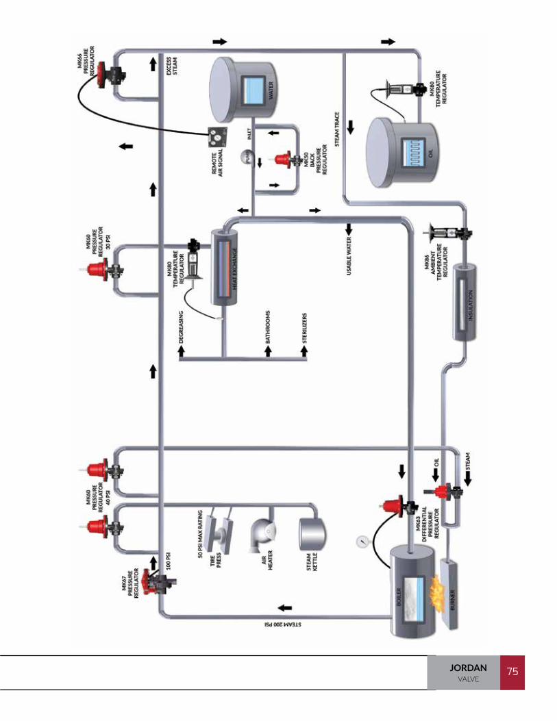
75JORDANVALVE
75
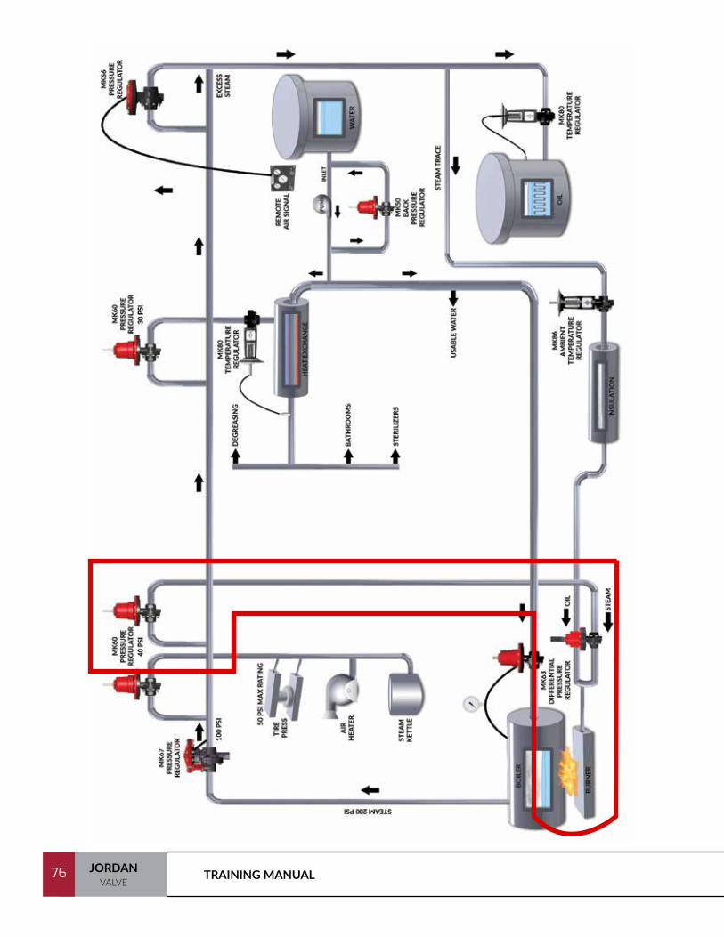
TRAINING MANUAL76 JORDANVALVE
76

77JORDANVALVE
77
The source of steam, of course, is water heated past its boiling point. This process takes place in a boiler. Many manufacturing plants have at least one boiler.
In our “typical plant,” note the boiler at the bottom left side of the process. The boiler requires oil (or other fuel) to produce heat, and water to produce steam at 200 psi (14 bar). Note the oil supply tank (bottom right hand side) and water tank above the oil.
STEAM FOR BURNER APPLICATIONS

TRAINING MANUAL78 JORDANVALVE
78

79JORDANVALVE
79
We’ll begin our look at steam production at the fuel oil tank itself. It is this fuel oil that will eventually produce a flame which will boil the water to produce steam.
Fuel oil is normally trucked or piped into a storage tank for eventual use. Eventually the oil will be piped into the plant, fed into the burner (a device which creates the flame), and be consumed in steam production. Because most fuels are likely to thicken beyond their flowing state in cold weather, these tanks must be kept warm.
As the oil is transported through the piping to the burner, it needs to be heated so as to remain liquid. This is accomplished by wrapping the pipe with copper “tracing” lines and then wrapping the “traced” pipe with insulation.
The MK86 Ambient Temperature (Ambi-Temp) Regulator is used to automatically turn the steam on and off as the temperature surrounding the valve decreases or increases around the set point. This protects the line from freezing, as well as reduces energy consumption (See Conserving Energy and Preventing Freeze Ups at the back of this section on page 142).
FUEL OIL APPLICATIONS
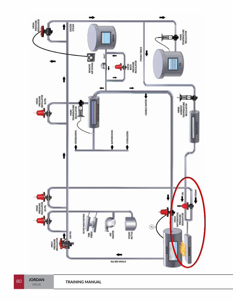
TRAINING MANUAL80 JORDANVALVE
80

81JORDANVALVE
81
Above is the schematic is the MK63 Differential/Atomizing valve with the fuel oil entering through the top dome area and the steam entering through the valve body. This valve is used to maintain steam pressure at a constant differential from the oil pressure. This assures effective atomization of the fuel oil into droplets (mist) so that a flame can be produced.
BURNER APPLICATION
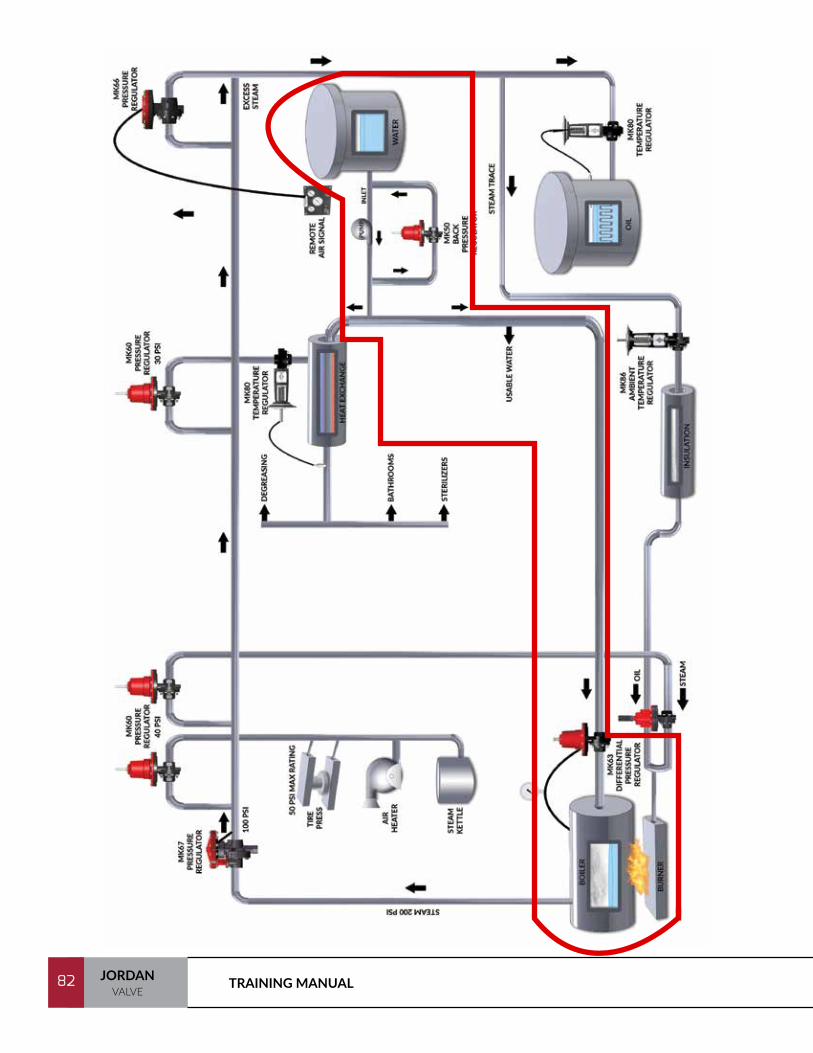
TRAINING MANUAL82 JORDANVALVE
82

83JORDANVALVE
83
Water is used throughout the plant, but it needs to be pressurized with a pumping station so that it can be piped and used effectively. So that the pump doesn’t over pressurize the water system, a Back Pressure Regulating Valve is used to recirculate the water to the suction side of the pump when pressure exceeds a predetermined set point. This assures trouble free pump operation as well as protection from bursting pipes (See Eliminating Pump Wear With Back Pressure Regulation at the end of this section).
Since the pump must be capable of maintaining water pressure throughout the plant, it is likely that the pump will be producing 250-300 psi water at its outlet. As the water line returns back down to the boiler, regulation becomes critical for boiler feedwater control.
At this point, the 250 psi water is reduced to a pressure equal to Boiler Pressure (notice the tap on top of the boiler running to the top of the dome of the MK63) plus whatever differential needs to be maintained. With a 200 psi steam pressure outlet and a normal differential requirement of 15 psi, the MK63 will reduce the water pressure from 300 psi to 215 psi before it enters the actual Electric Boiler Feedwater Control Valve (see Boiler Feedwater Application at the back of this section). This valve throttles open and closed, based on the water level in the boiler drum. Normally, it is done electrically with a mechanical float type device that moves up and down on a wire wound coil and creates a resistance. This varies the electric signal to between 0-185 ohm to the Electric Control Valve and enough water is maintained to produce the required amount of steam.
BOILER FEEDWATER APPLICATION
MK50 BACK PRESSURE
REGULATOR
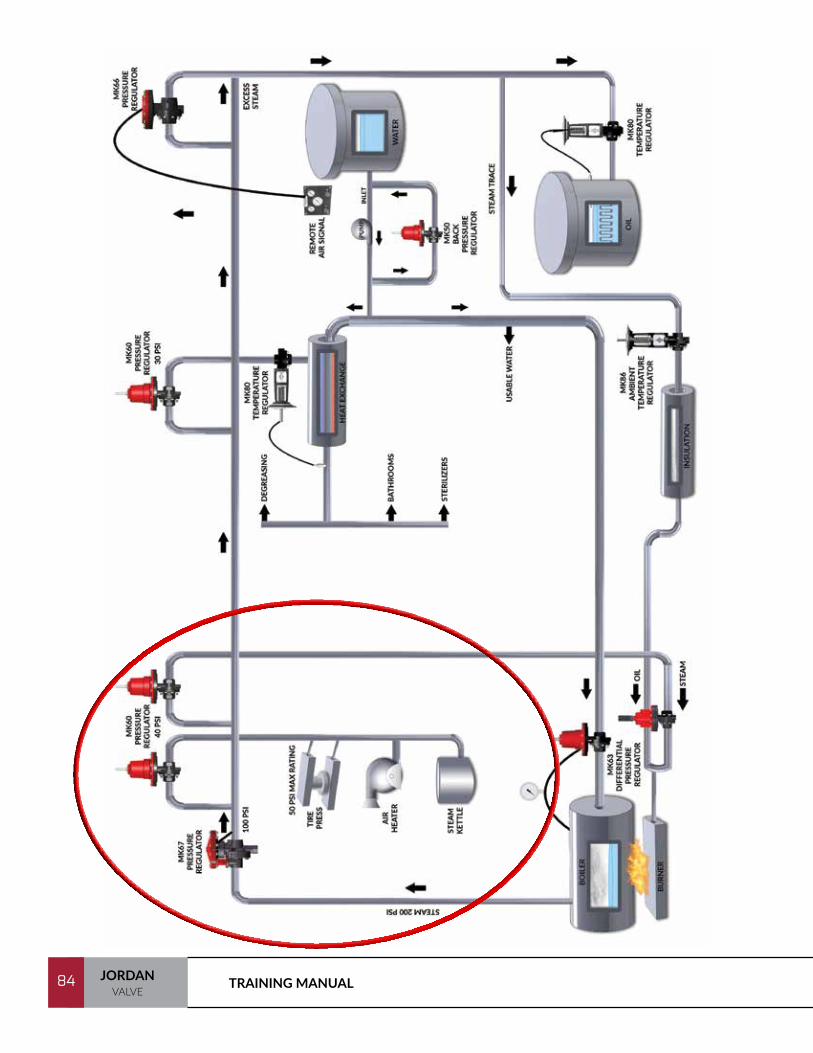
TRAINING MANUAL84 JORDANVALVE
84

85JORDANVALVE
85
Now that 200 psi steam has been generated, it can be put to work in the plant. As shown in the earlier illustration, this might involve using the steam: To blow up and cure rubber tires in a tire press, for heating the plant with air heaters, or brewing beer in a steam kettle.
If we go back to the steam required to heat the fuel oil tank, we see a MK66 Air Loaded Regulator is used to regulate the pressure of the main steam line to a much lower pressure at the tank (See Application with a Wide Pressure Range at the end of this section). The steam may also be used to control the temperature of a number of different processes from heating water for the showers to maintaining the temperature inside a sterilized fermentation process. Normally, a heat exchanger would be used to take the heat of the steam and transfer this heat to another liquid or gas (See Temperature Regulation with Heat Exchangers).
There are unlimited uses for these products. You will find potential applications for Jordan pressure regulators, temperature regulators, and control valves in virtually any plant from hospitals to military bases, chrome plating companies to food processing companies, and from refineries to power plants.
The important point to remember is that Jordan Valve’s main thrust is in the control of those “utilities”– steam, water, air, and gas – that help facilitate the process, not necessarily control the process.
VARIOUS STEAM APPLICATIONS

TRAINING MANUAL86 JORDANVALVE
86
Chemical, water, and oil lines need to be steam traced to prevent freeze-ups. However, as the cost of energy (especially steam) increases, a considerable amount of money is wasted by leaving steam lines open continuously.
By using the Mark 86 steam tracing valve, you can eliminate the possibilities of freeze-up (because the plant foreman forgot to turn the valve off) as well as save a substantial amount on wasted steam. Normal range; 2-55°F.
The Mark 86 can be adjusted in the filled within the full range of the valve. It has a set point indicator as well as a stem position indicator for local read out.
CONSERVING ENERGY AND PREVENTING FREEZE UP

87JORDANVALVE
87
A customer's pump was constantly wearing out due to the pump operating against a high head pressure. As the back pressure against the pump outlet rises, the pump must work harder. The Mark 50 back pressure regulator will eliminate the high head pressure. As the process pressure reaches the set point, the back pressure regulating valve will begin to open to reduce the back pressure.
With the short stroke of the Sliding Gate seat design, back pressure can be controlled very precisely. The 1/32" overlap provides the tight shutoff needed in the back pressure.
ELIMINATING PUMP WEAR
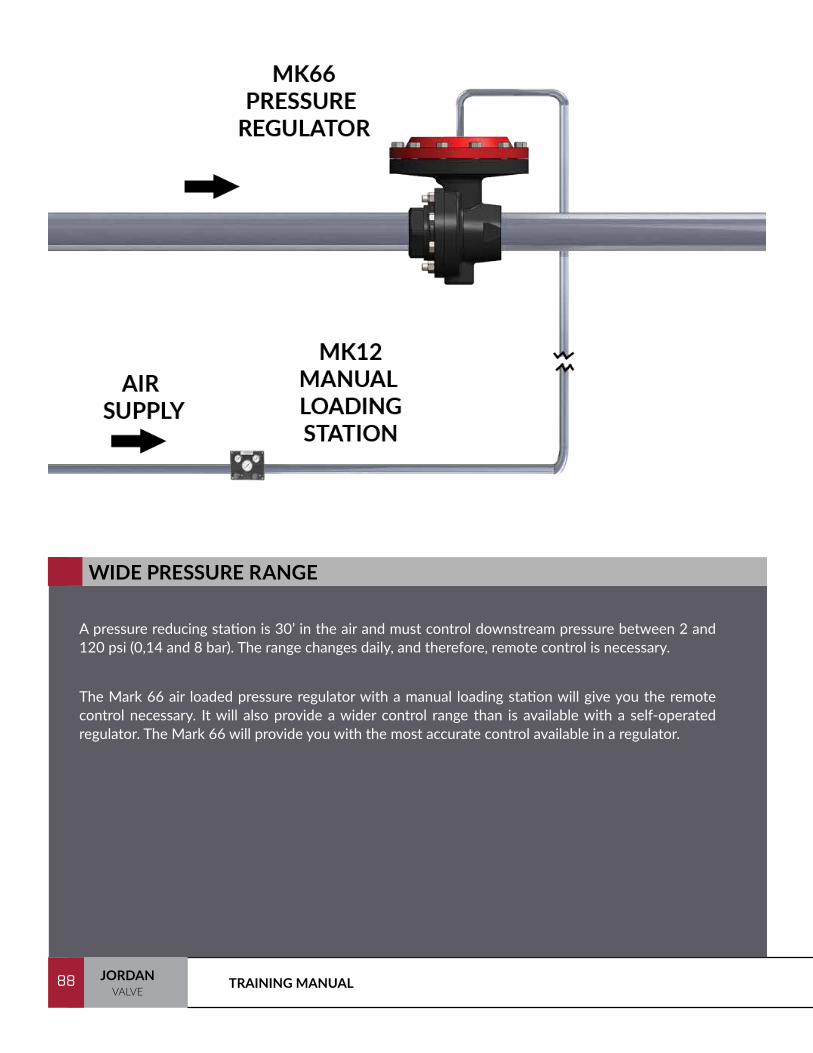
TRAINING MANUAL88 JORDANVALVE
88
A pressure reducing station is 30’ in the air and must control downstream pressure between 2 and 120 psi (0,14 and 8 bar). The range changes daily, and therefore, remote control is necessary.
The Mark 66 air loaded pressure regulator with a manual loading station will give you the remote control necessary. It will also provide a wider control range than is available with a self-operated regulator. The Mark 66 will provide you with the most accurate control available in a regulator.
WIDE PRESSURE RANGE
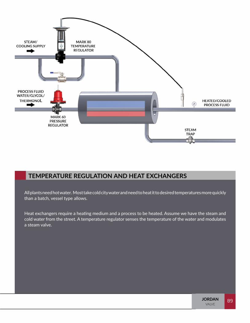
89JORDANVALVE
89
All plants need hot water. Most take cold city water and need to heat it to desired temperatures more quickly than a batch, vessel type allows.
Heat exchangers require a heating medium and a process to be heated. Assume we have the steam and cold water from the street. A temperature regulator senses the temperature of the water and modulates a steam valve.
TEMPERATURE REGULATION AND HEAT EXCHANGERS

TRAINING MANUAL90 JORDANVALVE
90
A variation of the temperature regulator is referred to as an Ambient Temperature Sensing Steam Tracing Valve. These valves sense the temperature of the air around the actuator and stroke the valve open as temperature approaches the set point. They are generally used for the steam tracing of oil, gas, water or chemical lines that must be kept from freezing.
Extracted from: Basics of Industrial Steam Utilization
In oil refineries, petroleum processing plants, and any industry handling heavy liquids, there are often times when it is necessary to heat a product before it can be moved. Viscous fluids become extremely difficult, and sometimes impossible, to pump if they cool below a certain temperature. To avoid this, it is necessary to supply heat to the product to keep it fluid enough to flow without too much work being expended by the pumps.
As you may know, steam tracing is one of the most practical methods used to provide supplemental heat to process lines to protect the product, instruments, valves, and other automatic controls from low process- fluid temperatures. Steam tracing can be used to prevent freezing, solidification, or separation, particularly important in lines that cannot be flushed, blown down, or drained while the process unit or equipment is on stream.
In its simplest terms, steam tracing consists of applying steam to the areas requiring such protection by means of tubing or small sized pipe that follows the contours of the product line or equipment to provide the level of heat required.
There are three general types of steam tracing:
• External
• Internal
• Jacketing
We will briefly look into all three methods, and explain the good and bad features of each, with the help of the figure shown on the next page.
STEAM TRACING

91JORDANVALVE
91
In the external method, pipe or tubing of small bore carrying steam is either wrapped around the product line or vessel, or else parallel runs are placed outside the product line, with the transfer of the heat taking place through the pipe wall. This is the more common method of the three, as it is the simplest and cheapest, it’s easy to repair or alter, and there is no possibility of cross-contamination between the product and the steam or condensate. The disadvantages are that the heat transfer rate between the tracer and the pipe is often unpredictable, consequently there is usually a slow heat up rate if the product is allowed to cool, and a high temperature drop is required between the tracer and the pipe, which often results in uneven temperature distribution.
The illustration to the right shows the usual manner in which the external tracer is applied. Actual tests have shown that there is a slight advantage to placing the tracer line below the product line when this method is used, but this is seldom done, due to the easier maintenance if the tracer is above the product line.
If more than one tracer line is used on the outside of the pipe, then it is recommended that they be on different traps. This will ensure that some heating will still take place if one trap becomes clogged or stuck in the closed position. Also, for more uniform temperatures, two parallel tracer lines along a product pipe should, if possible, be fed in opposite directions so that a drop in temperature along the tracer lines will cancel each other out and maintain a more uniform total effect on the product line.
When insulation is placed over the traced line, it requires a larger diameter insulation (often 1" or more larger than normally would be used). This often leads to odd sizes being required, which in turn raises the price on the insulation.
On external tracing, if there is too much heat transfer to the product, it is usual to place some blocking between the tracer and the product line, or else place a thin layer of insulating paper between them. It is essential that the tracer be spaced uniformly along long pipe runs, and it should be fastened properly so as to permit some movement, without danger of it working loose or pulling away from the product line.
Internal steam tracing is considerably more difficult to obtain. It requires some complicated fittings where the steam line enters and leaves the product pipe. This often requires packing glands or stuffing boxes, and makes repairs very difficult. There is also the danger of cross contamination between the steam and the product. A much faster heat- up is obtained, however, and a much better heat transfer than is obtained with the external method. As you can see, especially if the tracer line is coiled within the product line.

TRAINING MANUAL92 JORDANVALVE
92
As illustrated on the previous page, internal steam tracing is considerably more difficult to obtain. It requires some complicated fittings where the steam line enters and leaves the product pipe. This often requires packing glands or stuffing boxes, and makes repairs very difficult. There is also the danger of cross contamination between the steam and the product. A much faster heat-up is obtained, however, and a much better heat transfer than is obtained with the external method. As you can see, especially if the tracer line is coiled within the product line.
The jacketed method more closely resembles a typical double pipe heat exchanger. Here, the steam heating is provided from outside the product line, and there is much more heating surface available than with either of the other two methods. There is a lower temperature drop possible between the tracer medium and the product with this system due to the greater amount of transfer surface. The heat transfer rate is more predictable, and the heat-up from cold is faster. However, the cost is higher than either of the other two methods, it is difficult to repair, and there is still danger of cross-contamination.
Many suppliers have placed special piping, valves, and fittings on the market for steam tracing or jacketing. Pipe is available which has a formed tracer passage built into one side of it. Also, there are valves and fittings made with cast-in tracing passages. However, it is fairly easy for the average maintenance man with common facilities available to adapt tubing and small diameter pipe to his own needs. The usual method is to use copper tubing of about 3/8", 1/2", or 3/4" O.D., and either lay it along the pipe or wrap it around the product line as necessary. Valves and fittings are easily handled in this manner.
AMBIENT TEMPERATURE REGULATORS CONTINUED
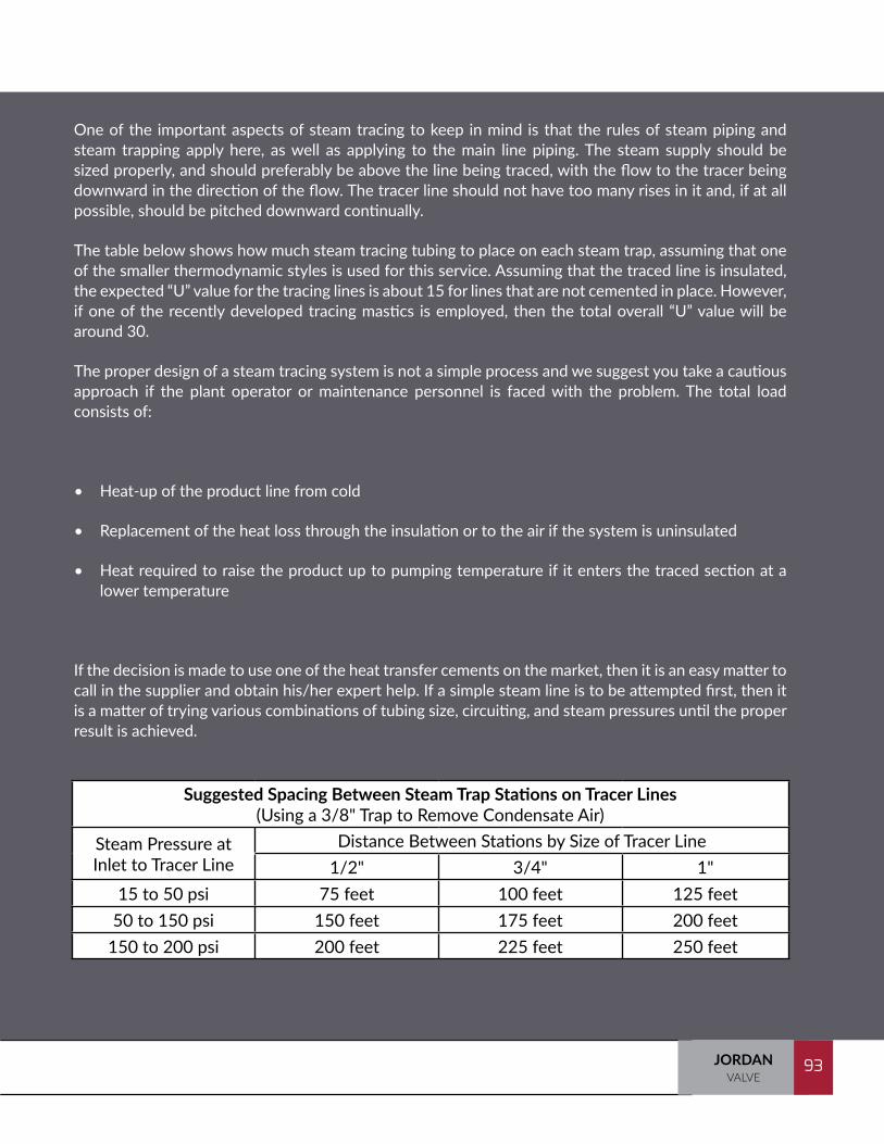
93JORDANVALVE
93
One of the important aspects of steam tracing to keep in mind is that the rules of steam piping and steam trapping apply here, as well as applying to the main line piping. The steam supply should be sized properly, and should preferably be above the line being traced, with the flow to the tracer being downward in the direction of the flow. The tracer line should not have too many rises in it and, if at all possible, should be pitched downward continually.
The table below shows how much steam tracing tubing to place on each steam trap, assuming that one of the smaller thermodynamic styles is used for this service. Assuming that the traced line is insulated, the expected “U” value for the tracing lines is about 15 for lines that are not cemented in place. However, if one of the recently developed tracing mastics is employed, then the total overall “U” value will be around 30.
The proper design of a steam tracing system is not a simple process and we suggest you take a cautious approach if the plant operator or maintenance personnel is faced with the problem. The total load consists of:
• Heat-up of the product line from cold
• Replacement of the heat loss through the insulation or to the air if the system is uninsulated
• Heat required to raise the product up to pumping temperature if it enters the traced section at a lower temperature
If the decision is made to use one of the heat transfer cements on the market, then it is an easy matter to call in the supplier and obtain his/her expert help. If a simple steam line is to be attempted first, then it is a matter of trying various combinations of tubing size, circuiting, and steam pressures until the proper result is achieved.
Suggested Spacing Between Steam Trap Stations on Tracer Lines(Using a 3/8" Trap to Remove Condensate Air)
Steam Pressure at Inlet to Tracer Line
Distance Between Stations by Size of Tracer Line1/2" 3/4" 1"
15 to 50 psi 75 feet 100 feet 125 feet50 to 150 psi 150 feet 175 feet 200 feet
150 to 200 psi 200 feet 225 feet 250 feet
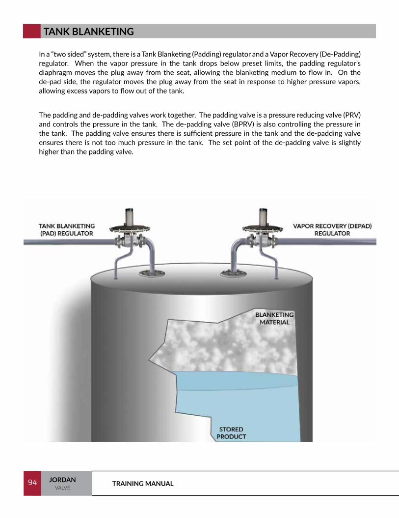
TRAINING MANUAL94 JORDANVALVE
94
TANK BLANKETING
In a “two sided” system, there is a Tank Blanketing (Padding) regulator and a Vapor Recovery (De-Padding) regulator. When the vapor pressure in the tank drops below preset limits, the padding regulator’s diaphragm moves the plug away from the seat, allowing the blanketing medium to flow in. On the de-pad side, the regulator moves the plug away from the seat in response to higher pressure vapors, allowing excess vapors to flow out of the tank.
The padding and de-padding valves work together. The padding valve is a pressure reducing valve (PRV) and controls the pressure in the tank. The de-padding valve (BPRV) is also controlling the pressure in the tank. The padding valve ensures there is sufficient pressure in the tank and the de-padding valve ensures there is not too much pressure in the tank. The set point of the de-padding valve is slightly higher than the padding valve.
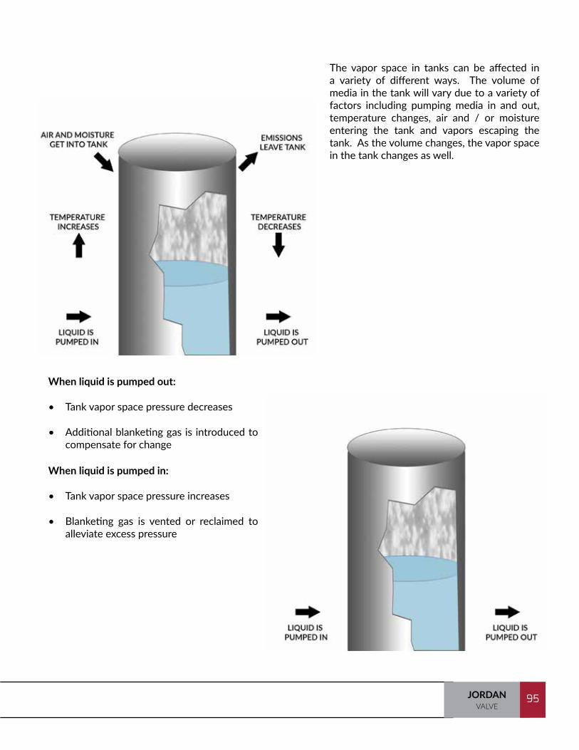
95JORDANVALVE
95
The vapor space in tanks can be affected in a variety of different ways. The volume of media in the tank will vary due to a variety of factors including pumping media in and out, temperature changes, air and / or moisture entering the tank and vapors escaping the tank. As the volume changes, the vapor space in the tank changes as well.
When liquid is pumped out:
• Tank vapor space pressure decreases
• Additional blanketing gas is introduced to compensate for change
When liquid is pumped in:
• Tank vapor space pressure increases
• Blanketing gas is vented or reclaimed to alleviate excess pressure
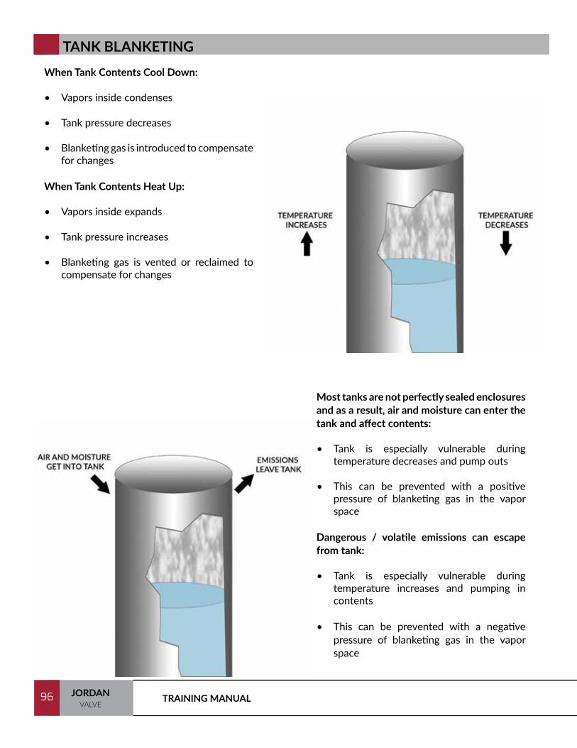
TRAINING MANUAL96 JORDANVALVE
96
When Tank Contents Cool Down:
• Vapors inside condenses
• Tank pressure decreases
• Blanketing gas is introduced to compensate for changes
When Tank Contents Heat Up:
• Vapors inside expands
• Tank pressure increases
• Blanketing gas is vented or reclaimed to compensate for changes
Most tanks are not perfectly sealed enclosures and as a result, air and moisture can enter the tank and affect contents:
• Tank is especially vulnerable during temperature decreases and pump outs
• This can be prevented with a positive pressure of blanketing gas in the vapor space
Dangerous / volatile emissions can escape from tank:
• Tank is especially vulnerable during temperature increases and pumping in contents
• This can be prevented with a negative pressure of blanketing gas in the vapor space
TANK BLANKETING
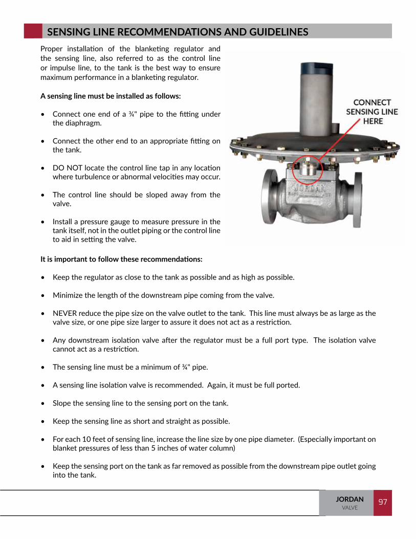
97JORDANVALVE
97
Proper installation of the blanketing regulator and the sensing line, also referred to as the control line or impulse line, to the tank is the best way to ensure maximum performance in a blanketing regulator.
A sensing line must be installed as follows:
• Connect one end of a ¾" pipe to the fitting under the diaphragm.
• Connect the other end to an appropriate fitting on the tank.
• DO NOT locate the control line tap in any location where turbulence or abnormal velocities may occur.
• The control line should be sloped away from the valve.
• Install a pressure gauge to measure pressure in the tank itself, not in the outlet piping or the control line to aid in setting the valve.
It is important to follow these recommendations:
• Keep the regulator as close to the tank as possible and as high as possible.
• Minimize the length of the downstream pipe coming from the valve.
• NEVER reduce the pipe size on the valve outlet to the tank. This line must always be as large as the valve size, or one pipe size larger to assure it does not act as a restriction.
• Any downstream isolation valve after the regulator must be a full port type. The isolation valve cannot act as a restriction.
• The sensing line must be a minimum of ¾" pipe.
• A sensing line isolation valve is recommended. Again, it must be full ported.
• Slope the sensing line to the sensing port on the tank.
• Keep the sensing line as short and straight as possible.
• For each 10 feet of sensing line, increase the line size by one pipe diameter. (Especially important on blanket pressures of less than 5 inches of water column)
• Keep the sensing port on the tank as far removed as possible from the downstream pipe outlet going into the tank.
SENSING LINE RECOMMENDATIONS AND GUIDELINES
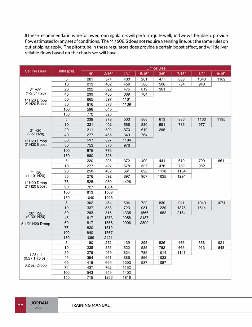
TRAINING MANUAL98 JORDANVALVE
98
If these recommendations are followed, our regulators will perform quite well, and we will be able to provide flow estimates for any set of conditions. The MK608IS does not require a sensing line, but the same rules on outlet piping apply. The pitot tube in these regulators does provide a certain boost effect, and will deliver reliable flows based on the charts we will have.
Set Pressure Inlet (psi)Orifice Size
1/8" 3/16" 1/4" 5/16" 3/8" 7/16" 1/2" 9/16"
2" H20(1-2.5" H20)
1" H20 Droop2" H20 Boost
5 201 374 430 261 477 888 1043 116910 213 402 456 580 506 784 94320 222 392 475 619 36140 299 465 639 76460 665 897 116180 816 873 1139100 598 640150 770 825
3" H20(2-5" H20)
1" H20 Droop2" H20 Boost
5 239 373 503 560 613 886 1163 119510 231 402 566 580 591 783 97720 211 392 570 619 29540 277 465 649 76460 597 897 119480 753 873 976
100 675 776150 880 825
7" H20(4-10" H20)
1" H20 Droop2" H20 Boost
5 220 295 372 409 441 619 799 66110 277 427 578 527 476 732 98220 258 462 661 893 1118 115435 276 592 897 967 1035 129475 525 980 142690 727 1364
100 813 1503150 1040 1926
28" H20(5-30" H20)
5-1/2" H20 Droop
5 302 454 604 722 839 941 1040 107410 337 533 723 981 1239 1378 151430 283 816 1335 1666 1982 215445 617 1373 2058 248760 817 1866 2906 289975 820 1812
100 840 1867150 1089 2421
1.25 psi(0.5 - 1.75 psi)
0.2 psi Droop
5 180 272 439 395 526 465 658 92110 235 333 522 535 783 665 913 84830 279 469 824 785 1014 114145 354 561 886 856 103360 418 669 1003 937 108775 427 762 1152
100 543 949 1402150 715 1266 1816

99JORDANVALVE
99
NOTES:
TRAINING MANUAL100 JORDANVALVE
100
JORDAN VALVE COMPETITION
This section provides a brief overview of our primary competitors by valve category. The categories are broken out as follows:
Pressure Regulators (Includes PRV and BPRV)Temperature RegulatorsTank Blanketing ValvesControl Valves
The list of competitors is not all inclusive but focused on those you will most likely encounter on a regular basis.
Pressure Regulators
• Fisher
• Cashco
• Spirax Sarco
• Spence Engineering
• Leslie Controls
• Schubert & Salzer
• Samson Controls
101JORDANVALVE
101
Temperature Regulators
• Trerice
• Watson McDaniel
• Leslie
• Spirax Sarco
• Spence Engineering
• Powers
• Robertshaw
Tank Blanketing
• Fisher
• Cashco (Valve Concepts)
• Protectoseal
• Shand & Jurs (L & J Technologies)
Control Valves
• Fisher
• Cashco
• Leslie Controls
• Samson
• Masoneilan
• Valtek
The list of competitors is not all inclusive but we have focused on those you will most likely encounter on a regular basis.

TRAINING MANUAL102 JORDANVALVE
102
Fisher is part of the Emerson Process Management group, a division of Emerson Electric. Emerson Electric is an American multinational corporation headquartered in Ferguson, Missouri. Fisher manufactures in a variety of locations globally and works through a large network of reps and distributors. Fisher is the industry leader in industrial control valves and regulators. They have the broadest product offering in the industry.
FISHER
CASHCO
Spirax-Sarco Engineering plc is a multi-national engineering group that has its headquarters in Cheltenham, UK. The Group comprises two world leading engineering businesses: Spirax Sarco for steam specialties and Watson-Marlow for niche peristaltic pumps and associated fluid path technologies. They have a wide product portfolio touching almost every aspect of steam and fluid processing infrastructure.
SPIRAX SARCO
Cashco, Inc. is a manufacturer and worldwide marketer of a broad line of industrial control products. Cashco owns and markets products under Cashco and Valve Concepts names. Products include control valves, regulators, controllers, pressure/vacuum relief vents, and flame and detonation arrestors. Cashco is best known for regulators, ranging from 1/4" to 6" (DN8 to DN150) in size for air, liquids, and steam. Cashco , Inc. services customers in industries including chemical, terminal storage, oil & gas, electronics, food and pharmaceutical through a worldwide network of offices and representatives.
The Valve Concepts brand is a leader in tank storage with its pilot operated technology in both blanketing valves and relief vents, allowing for tighter control of vapor spaces. This leads to fewer emissions and less product loss. Cashco’s Germany branch has developed the newest line of flame and detonation arrestors on the market, giving customers more flexibility while maintaining the highest level of quality.
The Ranger QCT is the flagship of the Control Valve line, with patented technology to allow field service friendly characteristics with high pressure drop capabilities.
103JORDANVALVE
103
LESLIE CONTROLS
SCHUBERT & SALZER
Leslie Controls is also a division of Circor Energy. Located in Tampa, Florida, Leslie Controls has been manufacturing industrial products including control valves, shutoff valves, control instrumentation, steam conditioning systems, steam water heaters and regulators for more than a century.
Schubert & Salzer is based in Germany and manufactures Sliding Gate control valves and regulators, conventional and angle body globe valves, pinch valve and ball valves. They serve the U.S. market through their North Carolina locations.
SPENCE ENGINEERING
Spence Engineering Company is a division of Circor Energy. They have a strong presence in the steam equipment regulation field. They manufacture steam specialty & fluid control devices. Spence is headquartered in Walden, New York, with sales offices located throughout the United States, Europe, Asia, Central and South America, and the Middle East.
The SAMSON Group is comprised of SAMSON AG, global SAMSON sales subsidiaries, and ten manufacturing companies that provide flow control products including linear globe, rotary plug, ball, and butterfly control valves for the oil & gas, petrochemical, nuclear & traditional power, industrial chemical, household & personal chemical, food & beverage, pharmaceutical, solar thermal, mining & metals and HVAC industries.
SAMSON CONTROLS

TRAINING MANUAL104 JORDANVALVE
104
TRERICE
A Watts company, Powers has been involved in temperature control for over 100 years Their current focus is on automatic temperature control for commercial buildings.
POWERS
Trerice is a long time manufacturer of temperature regulators, pressure regulators, and control valves. Trerice temperature regulators provide temperature control without the need for an external power source, pressure regulators are suitable for a variety of pressure regulating and pressure reducing applications and pneumatic and electric operated control valves.
WATSON MCDANIELFor over 100 years, Watson McDaniel has been manufacturing a wide range of steam specialty and fluid products for the industrial marketplace. Their focus is on improving the efficiency of the operation of steam, compressed air, heat transfer and fluid systems.
Another long time manufacturer, Robertshaw’s product line includes level controls, vibration monitors and switches, control valves, regulators and wireless level technology.
ROBERTSHAW

105JORDANVALVE
105
PROTECTOSEAL
SHAND & JURS
A Flowserve brand, Valtek manufactures a complete line of globe style industrial control valves, positioners, high performance butterfly valves, triple-offset butterfly valves, eccentric plug valves, and actuators.
VALTEK
A leading manufacturer of products that conserve and control volatile emissions and protect low pressure storage tanks, vessels and processes from fire and explosion. Protectoseal offers an integrated line of pressure and vacuum relief vents, flame/detonation arresters and related vapor control devices used primarily in process industries.
An L & J Technologies brand, Shand & Jurs manufactures a line of conservation vents, vapor recovery systems, specialty valves, gas blanketing valves, tank fittings, and flame and detonation arresters.
Product matrices follow.
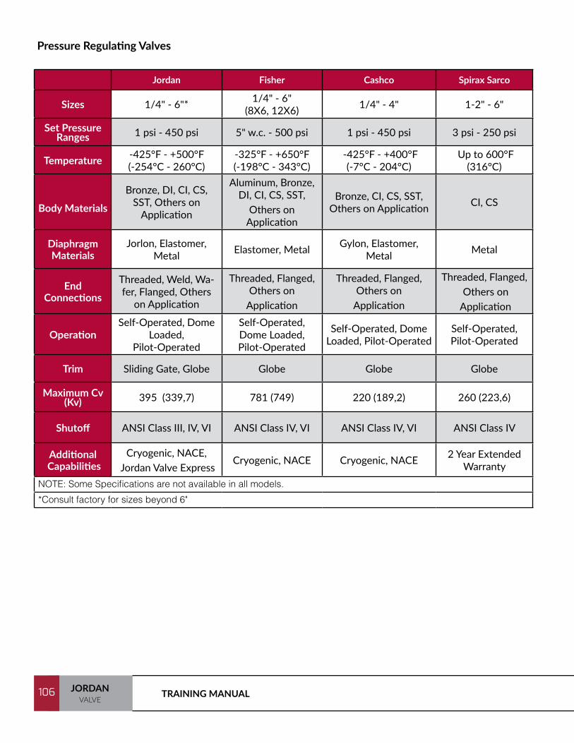
TRAINING MANUAL106 JORDANVALVE
106
Pressure Regulating Valves
Jordan Fisher Cashco Spirax Sarco Spence Leslie Controls Schubert & Salzer Samson
Sizes 1/4" - 6"* 1/4" - 6" (8X6, 12X6) 1/4" - 4" 1-2" - 6" 3/8" - 12" 1/2" - 4" 1-2" - 6" 1-2" - 16"
Set Pressure Ranges 1 psi - 450 psi 5" w.c. - 500 psi 1 psi - 450 psi 3 psi - 250 psi to 600 psi 2 psi - 300 psi 4.4 psi - 145 psi 0.75 psi - 400 psi
Temperature -425°F - +500°F (-254°C - 260°C)
-325°F - +650°F (-198°C - 343°C)
-425°F - +400°F (-7°C - 204°C)
Up to 600°F (316°C) Up to 750°F (399°C) Up to 750°F (399°C) -75°F - +445°F
(-59°C - 229°C) -5°F - +660°F
(-21°C - 349°C)
Body Materials
Bronze, DI, CI, CS, SST, Others on
Application
Aluminum, Bronze, DI, CI, CS, SST,
Others on Application
Bronze, CI, CS, SST, Others on Application CI, CS Bronze, CI, CS Bronze, DI, CI, CS, SST SST Bronze, Brass, SG Iron
(DI), CI, CS, SST
Diaphragm Materials
Jorlon, Elastomer, Metal Elastomer, Metal Gylon, Elastomer,
Metal Metal Elastomer, Metal Metal, Spiroflex, PTFE Elastomer, Composite, PTFE Elastomer, EPDM/PTFE
End Connections
Threaded, Weld, Wa-fer, Flanged, Others
on Application
Threaded, Flanged, Others on
Application
Threaded, Flanged, Others on
Application
Threaded, Flanged, Others on
Application
Threaded, Flanged, Others on Application
Threaded, Flanged Wafer Threaded, Flanged
OperationSelf-Operated, Dome
Loaded, Pilot-Operated
Self-Operated, Dome Loaded, Pilot-Operated
Self-Operated, Dome Loaded, Pilot-Operated
Self-Operated, Pilot-Operated
Self-Operated, Dome Loaded, Pilot-Operated
Self-Operated, Dome Loaded, Pilot-Operated Self-Operated
Self-Operated, Pilot-Operated
Trim Sliding Gate, Globe Globe Globe Globe Globe Globe Sliding Gate Globe
Maximum Cv (Kv) 395 (339,7) 781 (749) 220 (189,2) 260 (223,6) 1611 (1386) 124.8 (107) 393 (338) 2300 (2000)
Shutoff ANSI Class III, IV, VI ANSI Class IV, VI ANSI Class IV, VI ANSI Class IV ANSI Class IV, VI ANSI Class IV ANSI Class IV ANSI Class IV
Additional Capabilities
Cryogenic, NACE, Jordan Valve Express
Cryogenic, NACE Cryogenic, NACE 2 Year Extended Warranty
Quick Delivery Program, UL Series
Modified Linear and =% Flow Characteristic NACE
NOTE: Some Specifications are not available in all models.
*Consult factory for sizes beyond 6"
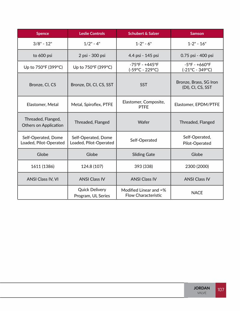
107JORDANVALVE
107
Jordan Fisher Cashco Spirax Sarco Spence Leslie Controls Schubert & Salzer Samson
Sizes 1/4" - 6"* 1/4" - 6" (8X6, 12X6) 1/4" - 4" 1-2" - 6" 3/8" - 12" 1/2" - 4" 1-2" - 6" 1-2" - 16"
Set Pressure Ranges 1 psi - 450 psi 5" w.c. - 500 psi 1 psi - 450 psi 3 psi - 250 psi to 600 psi 2 psi - 300 psi 4.4 psi - 145 psi 0.75 psi - 400 psi
Temperature -425°F - +500°F (-254°C - 260°C)
-325°F - +650°F (-198°C - 343°C)
-425°F - +400°F (-7°C - 204°C)
Up to 600°F (316°C) Up to 750°F (399°C) Up to 750°F (399°C) -75°F - +445°F
(-59°C - 229°C) -5°F - +660°F
(-21°C - 349°C)
Body Materials
Bronze, DI, CI, CS, SST, Others on
Application
Aluminum, Bronze, DI, CI, CS, SST,
Others on Application
Bronze, CI, CS, SST, Others on Application CI, CS Bronze, CI, CS Bronze, DI, CI, CS, SST SST Bronze, Brass, SG Iron
(DI), CI, CS, SST
Diaphragm Materials
Jorlon, Elastomer, Metal Elastomer, Metal Gylon, Elastomer,
Metal Metal Elastomer, Metal Metal, Spiroflex, PTFE Elastomer, Composite, PTFE Elastomer, EPDM/PTFE
End Connections
Threaded, Weld, Wa-fer, Flanged, Others
on Application
Threaded, Flanged, Others on
Application
Threaded, Flanged, Others on
Application
Threaded, Flanged, Others on
Application
Threaded, Flanged, Others on Application
Threaded, Flanged Wafer Threaded, Flanged
OperationSelf-Operated, Dome
Loaded, Pilot-Operated
Self-Operated, Dome Loaded, Pilot-Operated
Self-Operated, Dome Loaded, Pilot-Operated
Self-Operated, Pilot-Operated
Self-Operated, Dome Loaded, Pilot-Operated
Self-Operated, Dome Loaded, Pilot-Operated Self-Operated
Self-Operated, Pilot-Operated
Trim Sliding Gate, Globe Globe Globe Globe Globe Globe Sliding Gate Globe
Maximum Cv (Kv) 395 (339,7) 781 (749) 220 (189,2) 260 (223,6) 1611 (1386) 124.8 (107) 393 (338) 2300 (2000)
Shutoff ANSI Class III, IV, VI ANSI Class IV, VI ANSI Class IV, VI ANSI Class IV ANSI Class IV, VI ANSI Class IV ANSI Class IV ANSI Class IV
Additional Capabilities
Cryogenic, NACE, Jordan Valve Express
Cryogenic, NACE Cryogenic, NACE 2 Year Extended Warranty
Quick Delivery Program, UL Series
Modified Linear and =% Flow Characteristic NACE
NOTE: Some Specifications are not available in all models.
*Consult factory for sizes beyond 6"

TRAINING MANUAL108 JORDANVALVE
108
Temperature Regulating Valves
Jordan Trerice Watson McDaniel Leslie Spirax Sarco Spence Powers Robertshaw
Sizes 1/4"-6" 1/2"-6" 1/2"-4" 1/2"-4" 1/2"-6" 1/2"-2" 1/2"-4" 1/2"-6"
Pressure Class ANSI 150-300 1/2"-2" 250 psig 2-1/2"-6" 125 psig
1/2"-2" 250 psig 2-1/2"-4" 125 psig ANIS 150-300 ANSI 125 - 300 250 NPT ANSI 125 - 250 ANSI 125 - 250
Cv's (Kv's) 0.0008 - 395 (0,0007 - 340)
0.12 - 340 (0,10 - 292)
2.8 - 196 (2,4 - 169)
1.8 - 125 (1,55 - 108)
3.48 - 260 (2,99 - 224)
0.40 - 33 (0,34 - 28)
0.25 -53 (21,5 - 46)
1 - 563 (0,86 - 484)
Temperature Ranges13 Ranges from -20°F to 450°F
(-29°C to 232°C)
13 Ranges from 20°F - 440°F
(-10°C - 225°C)
13 Ranges from 20°F - 440°F
(-10°C - 225°C)
14 Ranges from 20°F - 425°F
(-10°C - 218°C)
7 Ranges from 0°F - 340°F
(-18°C - 171°C)
10 Ranges from 45°F - 415°F
(-7,2°C - 212°C)
13 Ranges from 0°F - 330°F
(-18°C - 166°C)
13 Ranges from 15°F - 330°F
(-9°C - 166°C)
Body MaterialsDI, CI, Bronze, CS,
SST, Others on Application
Bronze, CI, CS, SST Bronze, CI, BR/SST Bronze, CI, CS CI, CS Bronze, DI Bronze, CI Bronze, CI
Body Styles Sliding Gate Globe Globe Globe Globe Globe Globe Globe
End Connections Flanged, Threaded, Weld
Flanged, Threaded, Union
Flanged, Threaded, Union Flanged, Threaded Flanged, Threaded Threaded, Union Threaded, Union Threaded Union,
Flanged
Operation Self-Operated, Pilot-Operated Self-Operated Self-Operated Self-Operated,
Pilot-OperatedSelf-Operated, Pilot-Operated Self-Operated Self-Operated Self-Operated
Bellows No Yes Yes Yes Yes Yes Yes Yes
Overheat Protection
Yes Yes Yes Yes Yes Yes No Yes
Capillary Lengths 8' Standard - up to 100'+ 8', 12', 16', 20' 8', 12', 16', 20', 24' 8', 25', 40' 6.5', 8', 13', 15' 8', 25', 40' 8', 15', 30' 1' - 50'
Key Features and Options
SWA, Sliding Gate Seat, Custom Sensing Bulbs,
Short Span, Three-Way
Double Seated, Three-Way
Double Seated, Three-Way
Pressure / Temperature
version
Various Pilot Configurations
with Electrical On/Off Override
Double Seated, Three-Way
Double Seated, Three-Way
Double Seated, Three-Way
NOTE: Some Specifications are not available in all models.
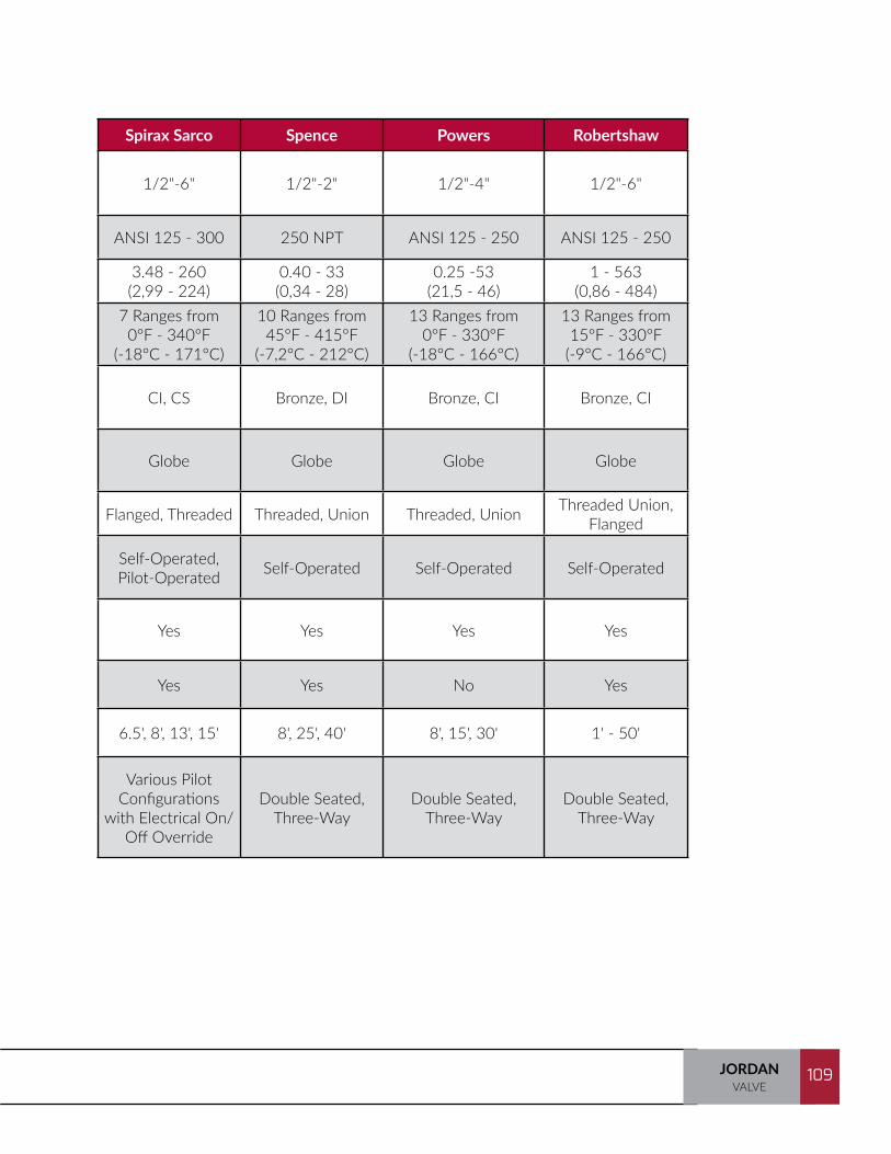
109JORDANVALVE
109
Jordan Trerice Watson McDaniel Leslie Spirax Sarco Spence Powers Robertshaw
Sizes 1/4"-6" 1/2"-6" 1/2"-4" 1/2"-4" 1/2"-6" 1/2"-2" 1/2"-4" 1/2"-6"
Pressure Class ANSI 150-300 1/2"-2" 250 psig 2-1/2"-6" 125 psig
1/2"-2" 250 psig 2-1/2"-4" 125 psig ANIS 150-300 ANSI 125 - 300 250 NPT ANSI 125 - 250 ANSI 125 - 250
Cv's (Kv's) 0.0008 - 395 (0,0007 - 340)
0.12 - 340 (0,10 - 292)
2.8 - 196 (2,4 - 169)
1.8 - 125 (1,55 - 108)
3.48 - 260 (2,99 - 224)
0.40 - 33 (0,34 - 28)
0.25 -53 (21,5 - 46)
1 - 563 (0,86 - 484)
Temperature Ranges13 Ranges from -20°F to 450°F
(-29°C to 232°C)
13 Ranges from 20°F - 440°F
(-10°C - 225°C)
13 Ranges from 20°F - 440°F
(-10°C - 225°C)
14 Ranges from 20°F - 425°F
(-10°C - 218°C)
7 Ranges from 0°F - 340°F
(-18°C - 171°C)
10 Ranges from 45°F - 415°F
(-7,2°C - 212°C)
13 Ranges from 0°F - 330°F
(-18°C - 166°C)
13 Ranges from 15°F - 330°F
(-9°C - 166°C)
Body MaterialsDI, CI, Bronze, CS,
SST, Others on Application
Bronze, CI, CS, SST Bronze, CI, BR/SST Bronze, CI, CS CI, CS Bronze, DI Bronze, CI Bronze, CI
Body Styles Sliding Gate Globe Globe Globe Globe Globe Globe Globe
End Connections Flanged, Threaded, Weld
Flanged, Threaded, Union
Flanged, Threaded, Union Flanged, Threaded Flanged, Threaded Threaded, Union Threaded, Union Threaded Union,
Flanged
Operation Self-Operated, Pilot-Operated Self-Operated Self-Operated Self-Operated,
Pilot-OperatedSelf-Operated, Pilot-Operated Self-Operated Self-Operated Self-Operated
Bellows No Yes Yes Yes Yes Yes Yes Yes
Overheat Protection
Yes Yes Yes Yes Yes Yes No Yes
Capillary Lengths 8' Standard - up to 100'+ 8', 12', 16', 20' 8', 12', 16', 20', 24' 8', 25', 40' 6.5', 8', 13', 15' 8', 25', 40' 8', 15', 30' 1' - 50'
Key Features and Options
SWA, Sliding Gate Seat, Custom Sensing Bulbs,
Short Span, Three-Way
Double Seated, Three-Way
Double Seated, Three-Way
Pressure / Temperature
version
Various Pilot Configurations
with Electrical On/Off Override
Double Seated, Three-Way
Double Seated, Three-Way
Double Seated, Three-Way
NOTE: Some Specifications are not available in all models.

TRAINING MANUAL110 JORDANVALVE
110
Tank Blanketing Valves
Fisher Jordan Valve* Jordan Valve* VCI (Cashco) Protectoseal Shand & Jurs
Operation Actuation Pressure Registration Model / Series Sizes Model / Series Sizes Model / Series Sizes Model / Series Sizes Model / Series Sizes
Padding
Self External ACE95jr 1/2" 695X 1/2" - 3/4" 1088** 1/2" Series 30 1/2" 94270 1/2"Self Internal Y690A 3/4" - 1" 608IS 3/4" - 1-1/4" 31-N*** 1/2" - 1" Series 30 1/2" 94270 1/2"Self Internal Y692 1-1/2" - 2" N/A N/A N/A N/ASelf External Y693 1-1/2" - 2" 608 1-1/2" - 2" 31-N*** 1-1/2" - 2" N/A N/APilot External ACE95 3/4" - 1" 695 3/4" - 1" 1078 1" Series 20 1" 94270**** 1"Pilot External ACE95SR 2" 695 2" 1078 2" Series 10 2" 94270 2"Pilot External 1190 1,2,3,4,6,8x6 688 1" - 2" N/A N/A N/A
De-Pad
Self Internal Y695A 3/4" - 1" 508 3/4" - 1-1/4" 31-B*** 1/2" - 1" N/A N/ASelf External Y696 1-1/2" - 2" 508 1-1/2" - 2" 31-B*** 1-1/2" - 2" N/A N/ASelf Internal or External 66R 2" - 4" 518 1", 2", 4" N/A N/A 94261***** 2" - 8"Pilot External 66RR 2" - 4" N/A N/A N/A N/APilot External 1290 1,2,3,4,6,8x6 N/A N/A N/A N/A
Pad / De-Pad External ACE97 Pad - 1/2" - 2" Depad 1" - 4" N/A N/A N/A N/A
*MK 508BPM and 608BPM are suitable for blanketing applications with the 515 actuator
**Internal or External Sensing
***Internal sensing standard. External optional
****Dip Tube also available
*****Referred to in Shand & Jurs data sheet as Vapor Recover Regulator and "Vent"
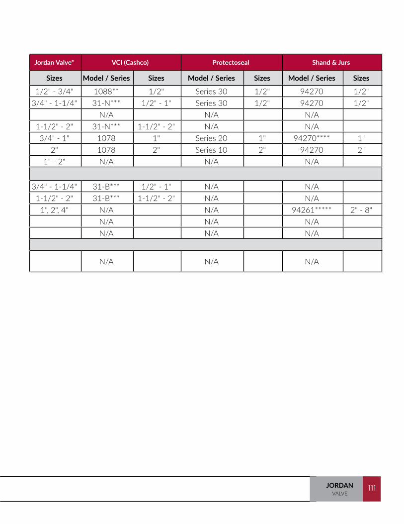
111JORDANVALVE
111
Fisher Jordan Valve* Jordan Valve* VCI (Cashco) Protectoseal Shand & Jurs
Operation Actuation Pressure Registration Model / Series Sizes Model / Series Sizes Model / Series Sizes Model / Series Sizes Model / Series Sizes
Padding
Self External ACE95jr 1/2" 695X 1/2" - 3/4" 1088** 1/2" Series 30 1/2" 94270 1/2"Self Internal Y690A 3/4" - 1" 608IS 3/4" - 1-1/4" 31-N*** 1/2" - 1" Series 30 1/2" 94270 1/2"Self Internal Y692 1-1/2" - 2" N/A N/A N/A N/ASelf External Y693 1-1/2" - 2" 608 1-1/2" - 2" 31-N*** 1-1/2" - 2" N/A N/APilot External ACE95 3/4" - 1" 695 3/4" - 1" 1078 1" Series 20 1" 94270**** 1"Pilot External ACE95SR 2" 695 2" 1078 2" Series 10 2" 94270 2"Pilot External 1190 1,2,3,4,6,8x6 688 1" - 2" N/A N/A N/A
De-Pad
Self Internal Y695A 3/4" - 1" 508 3/4" - 1-1/4" 31-B*** 1/2" - 1" N/A N/ASelf External Y696 1-1/2" - 2" 508 1-1/2" - 2" 31-B*** 1-1/2" - 2" N/A N/ASelf Internal or External 66R 2" - 4" 518 1", 2", 4" N/A N/A 94261***** 2" - 8"Pilot External 66RR 2" - 4" N/A N/A N/A N/APilot External 1290 1,2,3,4,6,8x6 N/A N/A N/A N/A
Pad / De-Pad External ACE97 Pad - 1/2" - 2" Depad 1" - 4" N/A N/A N/A N/A
*MK 508BPM and 608BPM are suitable for blanketing applications with the 515 actuator
**Internal or External Sensing
***Internal sensing standard. External optional
****Dip Tube also available
*****Referred to in Shand & Jurs data sheet as Vapor Recover Regulator and "Vent"
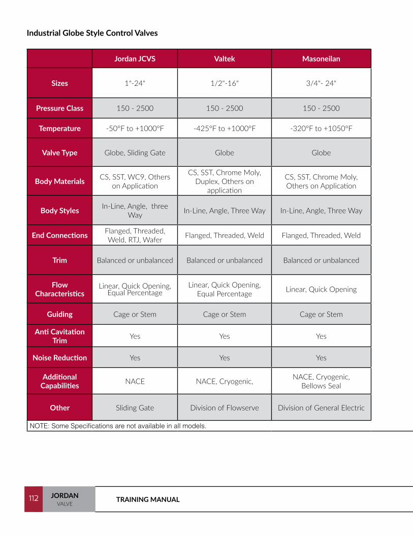
TRAINING MANUAL112 JORDANVALVE
112
Jordan JCVS Valtek Masoneilan Fisher Leslie Controls Samson
Sizes 1"-24" 1/2"-16" 3/4"- 24" 1"-30" 1" - 16" 1/4"- 24"
Pressure Class 150 - 2500 150 - 2500 150 - 2500 150 - 2500 150 - 4500 150-2500
Temperature -50°F to +1000°F -425°F to +1000°F -320°F to +1050°F -325°F to +1292°F -20°F to +1050°F (-29°C to +565°C) -325°F to +1292°F
Valve Type Globe, Sliding Gate Globe Globe Globe Globe Globe
Body Materials CS, SST, WC9, Others on Application
CS, SST, Chrome Moly, Duplex, Others on
application
CS, SST, Chrome Moly, Others on Application
CI, CS, SST, WC9, Others on Application CS, SST, WC9
Body Styles In-Line, Angle, three Way In-Line, Angle, Three Way In-Line, Angle, Three Way In-Line, Angle, Three Way In-line, Angle In-Line, Angle, Three Way
End Connections Flanged, Threaded, Weld, RTJ, Wafer Flanged, Threaded, Weld Flanged, Threaded, Weld Flanged, Threaded, Weld Flanged, Threaded, Weld,
RTJ Flanged, Threaded, Weld
Trim Balanced or unbalanced Balanced or unbalanced Balanced or unbalanced Balanced or unbalanced Balanced or unbalanced Balanced or unbalanced
Flow Characteristics
Linear, Quick Opening, Equal Percentage
Linear, Quick Opening, Equal Percentage Linear, Quick Opening Linear, Quick Opening Linear, Quick Opening,
Equal PercentageLinear, Quick Opening,
Equal Percentage
Guiding Cage or Stem Cage or Stem Cage or Stem Cage or Stem Cage or stem Cage or Stem
Anti Cavitation Trim Yes Yes Yes Yes Yes Yes
Noise Reduction Yes Yes Yes Yes Yes Yes
Additional Capabilities NACE NACE, Cryogenic, NACE, Cryogenic,
Bellows SealNACE, Cryogenic, Bellows
Seal NACE NACE, Cryogenic,
Other Sliding Gate Division of Flowserve Division of General Electric Market Leader, Division of Emerson Division of Circor Bellows Seal
NOTE: Some Specifications are not available in all models.
Industrial Globe Style Control Valves

113JORDANVALVE
113
Jordan JCVS Valtek Masoneilan Fisher Leslie Controls Samson
Sizes 1"-24" 1/2"-16" 3/4"- 24" 1"-30" 1" - 16" 1/4"- 24"
Pressure Class 150 - 2500 150 - 2500 150 - 2500 150 - 2500 150 - 4500 150-2500
Temperature -50°F to +1000°F -425°F to +1000°F -320°F to +1050°F -325°F to +1292°F -20°F to +1050°F (-29°C to +565°C) -325°F to +1292°F
Valve Type Globe, Sliding Gate Globe Globe Globe Globe Globe
Body Materials CS, SST, WC9, Others on Application
CS, SST, Chrome Moly, Duplex, Others on
application
CS, SST, Chrome Moly, Others on Application
CI, CS, SST, WC9, Others on Application CS, SST, WC9
Body Styles In-Line, Angle, three Way In-Line, Angle, Three Way In-Line, Angle, Three Way In-Line, Angle, Three Way In-line, Angle In-Line, Angle, Three Way
End Connections Flanged, Threaded, Weld, RTJ, Wafer Flanged, Threaded, Weld Flanged, Threaded, Weld Flanged, Threaded, Weld Flanged, Threaded, Weld,
RTJ Flanged, Threaded, Weld
Trim Balanced or unbalanced Balanced or unbalanced Balanced or unbalanced Balanced or unbalanced Balanced or unbalanced Balanced or unbalanced
Flow Characteristics
Linear, Quick Opening, Equal Percentage
Linear, Quick Opening, Equal Percentage Linear, Quick Opening Linear, Quick Opening Linear, Quick Opening,
Equal PercentageLinear, Quick Opening,
Equal Percentage
Guiding Cage or Stem Cage or Stem Cage or Stem Cage or Stem Cage or stem Cage or Stem
Anti Cavitation Trim Yes Yes Yes Yes Yes Yes
Noise Reduction Yes Yes Yes Yes Yes Yes
Additional Capabilities NACE NACE, Cryogenic, NACE, Cryogenic,
Bellows SealNACE, Cryogenic, Bellows
Seal NACE NACE, Cryogenic,
Other Sliding Gate Division of Flowserve Division of General Electric Market Leader, Division of Emerson Division of Circor Bellows Seal
NOTE: Some Specifications are not available in all models.
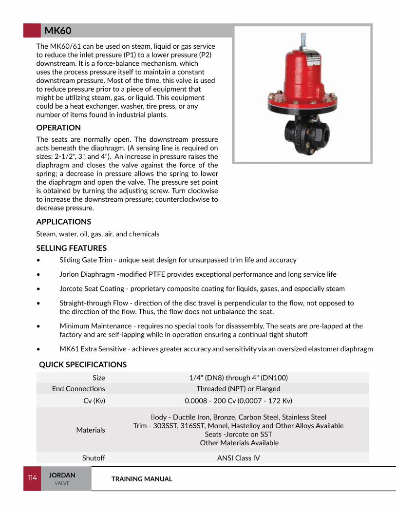
TRAINING MANUAL114 JORDANVALVE
114
The MK60/61 can be used on steam, liquid or gas service to reduce the inlet pressure (P1) to a lower pressure (P2) downstream. It is a force-balance mechanism, which uses the process pressure itself to maintain a constant downstream pressure. Most of the time, this valve is used to reduce pressure prior to a piece of equipment that might be utilizing steam, gas, or liquid. This equipment could be a heat exchanger, washer, tire press, or any number of items found in industrial plants.
OPERATIONThe seats are normally open. The downstream pressure acts beneath the diaphragm. (A sensing line is required on sizes: 2-1/2", 3", and 4"). An increase in pressure raises the diaphragm and closes the valve against the force of the spring; a decrease in pressure allows the spring to lower the diaphragm and open the valve. The pressure set point is obtained by turning the adjusting screw. Turn clockwise to increase the downstream pressure; counterclockwise to decrease pressure.
SELLING FEATURES• Sliding Gate Trim - unique seat design for unsurpassed trim life and accuracy
• Jorlon Diaphragm -modified PTFE provides exceptional performance and long service life
• Jorcote Seat Coating - proprietary composite coating for liquids, gases, and especially steam
• Straight-through Flow - direction of the disc travel is perpendicular to the flow, not opposed to the direction of the flow. Thus, the flow does not unbalance the seat.
• Minimum Maintenance - requires no special tools for disassembly, The seats are pre-lapped at the factory and are self-lapping while in operation ensuring a continual tight shutoff
• MK61 Extra Sensitive - achieves greater accuracy and sensitivity via an oversized elastomer diaphragm
MK60
APPLICATIONSSteam, water, oil, gas, air, and chemicals
QUICK SPECIFICATIONSSize 1/4" (DN8) through 4" (DN100)
End Connections Threaded (NPT) or Flanged
Cv (Kv) 0.0008 - 200 Cv (0,0007 - 172 Kv)
Materials
Body - Ductile Iron, Bronze, Carbon Steel, Stainless SteelTrim - 303SST, 316SST, Monel, Hastelloy and Other Alloys Available
Seats -Jorcote on SST Other Materials Available
Shutoff ANSI Class IV

115JORDANVALVE
115
The Mark 601 and Mark 602 meet higher capacity requirements than standard regulators. The HighFlow Mark 601 has Cv’s as high as 50 (43Kv) and theSuper High Flow Mark 602 has Cv’s up to 70 (60,2Kv).
OPERATIONThe seats are normally open. The downstream pressureacts beneath the diaphragm. An increase in pressure raises the diaphragm and closes the valve against the force of the spring; a decrease in pressure allows the spring to lower the diaphragm and open the valve. The pressure set point is obtained by turning the adjusting screw. Turn clockwise to increase the downstream pressure; counterclockwise to decrease pressure.
SELLING FEATURES• Sliding Gate Trim - unique seat design for unsurpassed trim life and accuracy
• Jorcote Seat Coating - ceramic composite for liquids, gases, and especially steam
• Straight-through Flow - direction of the disc travel is perpendicular to the flow, not opposed to the di-rection of the flow. Thus, the flow does not unbalance the seat.
• Minimum Maintenance - requires no special tools for disassembly, The seats are pre-lapped at the fac-tory and are self-lapping while in operation ensuring a continual tight shutoff
• Jorlon
APPLICATIONSSteam, water, oil, gas, air and chemicals
QUICK SPECIFICATIONSSize 1-1/2" (DN40) & 2" (DN50)
End Connections Threaded, ANSI or DIN Flanges
Cv (Kv) 25 – 70 Cv (21,5 – 60 Kv)
Materials
Body - Ductile Iron, Bronze, Carbon Steel, Stainless SteelTrim - 303SST or 316SSTSeats -Jorcote on SST *
Other Materials AvailableShutoff ANSI Class IV
MK601/602

TRAINING MANUAL116 JORDANVALVE
116
The Mark 62 internally piloted pressure regulator is designed for critical applications where space is limited, but highly accurate regulation is required. It features the Sliding Gate design in the main valve trim for superior performance and life when installed in clean gas and steam systems.
OPERATIONThe main valve is normally closed; the pilot valve is held normally open by an adjusting spring. The line fluid passes through the inlet pilot tube and the pilot valve to the main valve diaphragm. The pressure of a fluid forces the main diaphragm down to open the main valve seats. As the setpoint is reached, the downstream pressure acts beneath the pilot valve diaphragm to close the pilot valve, starving supply to the top of the main diaphragm causing the lower return spring to close the main valve. Due to precision manufacturing required for this internally piloted regulator, it is well suited for filtered media free of entrained particles or dirt.
SELLING FEATURES• Internal pilot — provides highly accurate performance in a compact, lightweight assembly.• Sliding Gate Seats
— Straight-through flow for reduced turbulence and quiet operation — Short stroke for fast response and accurate regulation. — Easily interchangeable Cv’s — Tight Shutoff
APPLICATIONSClean gas, steam, and air
QUICK SPECIFICATIONSSize 1/2" (DN15) though 2" (DN50)
End Connections Threaded (NPT) or Flanged
Cv (Kv) 2.5 to 30 Cv (2,15 - 26 Kv)
Materials
Body - Ductile Iron or Bronze Trim - Stainless Steel or 316SST
Seats - Jorcote on SST Other Materials Available Upon Request
Shutoff ANSI Class IV
MK62

117JORDANVALVE
117
The Mark 63 and Mark 64 differential pressure regulators are used to maintain a constant downstream pressure equal to the pressure loaded to the dome, plus spring force applied to the diaphragm. This valve is used to maintain a difference in pressure between two separate sources. The Mark 64 provides the same flow capacity as the Mark 63 but with less offset due to a larger diaphragm.
OPERATIONFor proper operation, there must be two separate lines: one for the process fluid and the other for the loading fluid. Basically, the valve will work exactly like the MK60, except the setpoint will equal the spring pressure plus whatever is loaded to the dome.
SELLING FEATURES• Mark 63/64 — maintains a constant differential between the pressure on the discharge side of the
regulator and the signal pressure loaded on the diaphragm. The MK64 features a larger effective dia-phragm area for greater sensitivity.
• Sliding Gate Seats — all of Jordan Valve’s differential regulators feature advanced Sliding Gate seat technology: straight-through flow for reduced turbulence and quiet operation; short stroke for fast response and accurate regulation; easily interchangeable Cv’s; tight shutoff
APPLICATIONSSteam, oil, gas, air, chemicals, and water
QUICK SPECIFICATIONS
Size MK63: 1/4" (DN8) through 2" (DN50) MK64: 1/4” (DN8) through 3/4” (DN20)
End Connections Threaded (NPT), ANSI flanged, or DIN flanged
Cv (Kv) 0.84 - 30 Cv (0,7 - 26 Kv)
MaterialsBody - Ductile Iron, Bronze, Carbon Steel, or Stainless Steel
Trim - 303SST or 316SSTSeats - Jorcote on SST
Shutoff ANSI Class IV
MK63/64

TRAINING MANUAL118 JORDANVALVE
118
Jordan vacuum regulators control very accurately and shutoff tightly to maintain the proper vacuum setting. They are used to maintain vacuums at predetermined settings and to regulate vacuums on evaporators, cookers, grinding fixtures, milking machines, altitude chambers and other vacuum systems.
OPERATIONThe Mark 65 is normally closed. The higher vacuum acts beneath the diaphragm. An increase in vacuum lowers the diaphragm and opens the valve; a decrease in vacuum raises the diaphragm to close the valve. To adjust the set point, the adjusting screw is turned clockwise to increase the vacuum or counterclockwise to decrease the vacuum.
SELLING FEATURES• High capacity. We are one of the few industrial regulator companies that manufacture vacuum
regulators through 2" (DN50) size. Most manufacturers of vacuum regulators are only in the 1/4" and 1/2" size.
• Sliding Gate seats. The short stroke of the Sliding Gate seat provides very accurate control of vacuum and provides very fast vacuum breaking.
APPLICATIONSVacuum regulation on evaporators, cookers, milking machines, grinding fixtures, and altitude chambers
QUICK SPECIFICATIONSSize 1/2" (DN15) through 2" (DN50)
End Connections Threaded (NPT) or Flanged
Cv (Kv) 2.5 - 30 Cv (2,15 - 26 Kv)
MaterialsBody - Ductile Iron, Bronze, Carbon Steel, or Stainless Steel
Trim - 316SST or 303SSSeats - Jorcote on SST or Plated SST
Shutoff ANSI Class IV
MK65

119JORDANVALVE
119
The MK66 air-loaded regulator is the most accurate regulator we produce. Because it uses air instead of a spring to opposedownstream pressure (P2), it eliminates the droop caused by the mechanical properties of range springs.
With the MK66, you can expect accuracy approaching that of a control valve at a great reduction in price. Furthermore, because it uses air rather than a spring, it has the capability of being set anywhere from 2-200 psi without a range change.
OPERATIONThe controlled pressure setting is adjusted by controlling the air pressure supplied to the top of the diaphragm. The valve disc is normally stroked up, closing the valve. Air pressure supplied to the top of the diaphragm opens the valve. As the outlet pressure begins to balance the loading pressure, the return spring moves the seats toward the closed position. To increase the controlled pressure, increase the air pressure to the top of the diaphragm.
Note: the dome can also be loaded with liquid or nitrogen.
SELLING FEATURES• High Rangeability: 35 – 40:1• Extremely Accurate: Droop of 2% - 5%• Sliding Gate seat
APPLICATIONSSteam, industrial gasses, air, lube oil, water and some chemicals. The Mark 66 is great for remote locations and / or frequently changing set points.
QUICK SPECIFICATIONSSize 1/2" (DN15) through 6" (DN150)
End Connections Threaded, ANSI Flanged, DIN Flanged, or JIS Flanged (10k,20k)
Cv (Kv) 2.5 - 395 Cv (2,2 - 340 Kv)
MaterialsBody - Ductile Iron, Bronze, Carbon Steel, Stainless Steel, or Cast Iron
Trim - 303SS or 316Seats - Jorcote on SST, Jordanic on SST, and Chrome Plated SST
Shutoff ANSI Class IV
MK66

TRAINING MANUAL120 JORDANVALVE
120
The Mark 67 Series is for critical pressure reducing applications and provides greater accuracy and lower offset than can be achieved with a self-operated regulator. The Mark 67 regulator combines the short stroke of the Sliding Gate with the action of a pilot valve to create a more accurate response. This allows for higher accuracy in a self-contained valve where control systems are not an option.
OPERATIONThe Mark 67 is normally closed. The upstream pressure enters the body and passes through the piping to the pilot valve. The pilot valve is normally open, allowing the upstream pressure to act on the top of the main valve diaphragm. This force pushes the stem downward, opening the main valve. As the downstream pressure rises to the setpoint, the pilot senses the rising pressure and begins to close, which throttles the flow to the main diaphragm. The pressure on the main valve diaphragm is bled off downstream, and the main valve closes.
SELLING FEATURES• Mark 67 — features the Mark 69 plug-style pilot valve for pressure settings ranging from 10 psi to 200
psi (0,69 bar to 13,79 bar)• Mark 67 with 69D Pilot —features a differential pilot for services where a constant differential must be
maintained between two fluids. It is commonly used for atomizing steam and oil for combustion on oil burners where a constant differential between the steam and oil must be maintained.
• Mark 67 with 69A Pilot — features an airloaded pilot that allows remote adjustment of your pressure setpoint by changing the air pressure loaded to the dome. This option is recommended where droop must be kept to a minimum, where remote control is needed, or where frequent setpoint changes may be required.
APPLICATIONSControlling the pressure of gaseous oxygen to furnaces at steel mills, controlling pressure of sealing oil on turbines, and pressure control on steam mains and distribution lines
QUICK SPECIFICATIONSSize 1/2" (DN15) through 6" (DN150)
End ConnectionsThreaded — FNPT, BSPT, BSPP (1/2" - 2" only)
ANSI Flanges — 150#, 300#DIN Flanges — PN10/16, PN25/40
Cv (Kv) 5.0 - 395 Cv (4,3 - 340 Kv)
MaterialsBody -Ductile Iron, Cast Iron, Carbon Steel, Stainless Steel
Trim - 303SS or 316SSSeats - Jorcote on SST or Jorcote/Jordanic
Shutoff ANSI Class IV
MK67
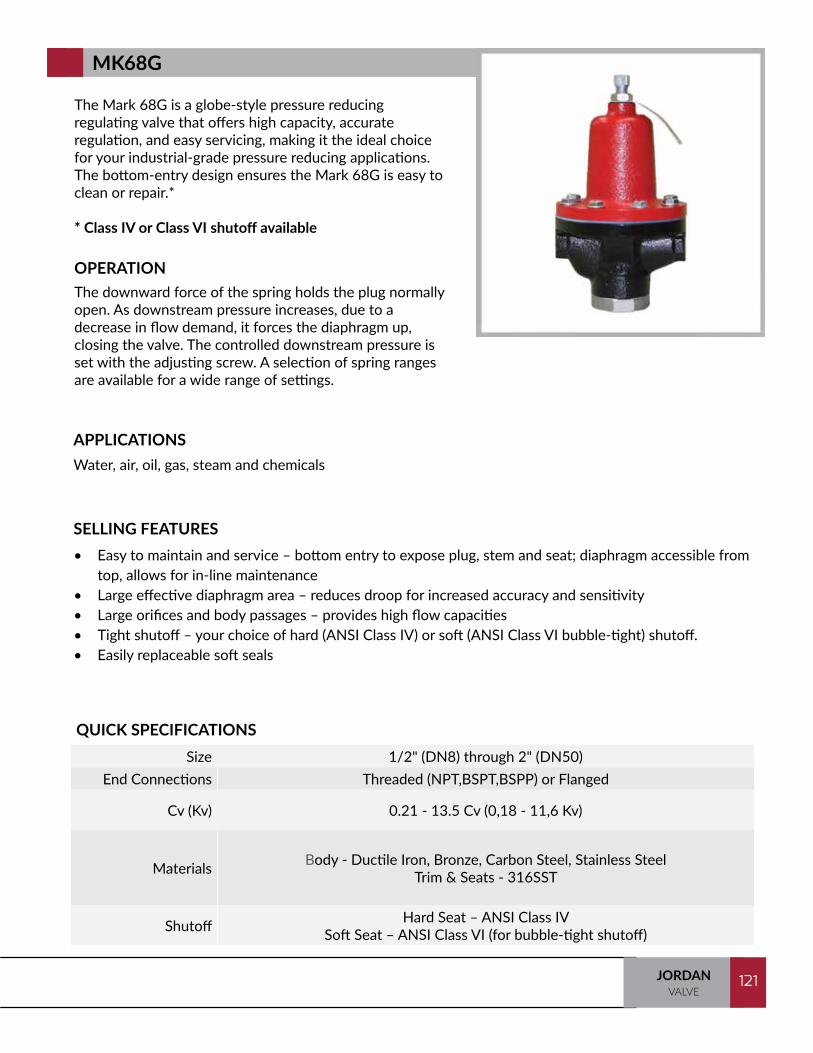
121JORDANVALVE
121
The Mark 68G is a globe-style pressure reducing regulating valve that offers high capacity, accurate regulation, and easy servicing, making it the ideal choice for your industrial-grade pressure reducing applications. The bottom-entry design ensures the Mark 68G is easy to clean or repair.*
* Class IV or Class VI shutoff available
OPERATIONThe downward force of the spring holds the plug normally open. As downstream pressure increases, due to a decrease in flow demand, it forces the diaphragm up, closing the valve. The controlled downstream pressure is set with the adjusting screw. A selection of spring ranges are available for a wide range of settings.
SELLING FEATURES• Easy to maintain and service – bottom entry to expose plug, stem and seat; diaphragm accessible from
top, allows for in-line maintenance• Large effective diaphragm area – reduces droop for increased accuracy and sensitivity• Large orifices and body passages – provides high flow capacities• Tight shutoff – your choice of hard (ANSI Class IV) or soft (ANSI Class VI bubble-tight) shutoff.• Easily replaceable soft seals
APPLICATIONSWater, air, oil, gas, steam and chemicals
QUICK SPECIFICATIONSSize 1/2" (DN8) through 2" (DN50)
End Connections Threaded (NPT,BSPT,BSPP) or Flanged
Cv (Kv) 0.21 - 13.5 Cv (0,18 - 11,6 Kv)
Materials Body - Ductile Iron, Bronze, Carbon Steel, Stainless SteelTrim & Seats - 316SST
Shutoff Hard Seat – ANSI Class IVSoft Seat – ANSI Class VI (for bubble-tight shutoff)
MK68G
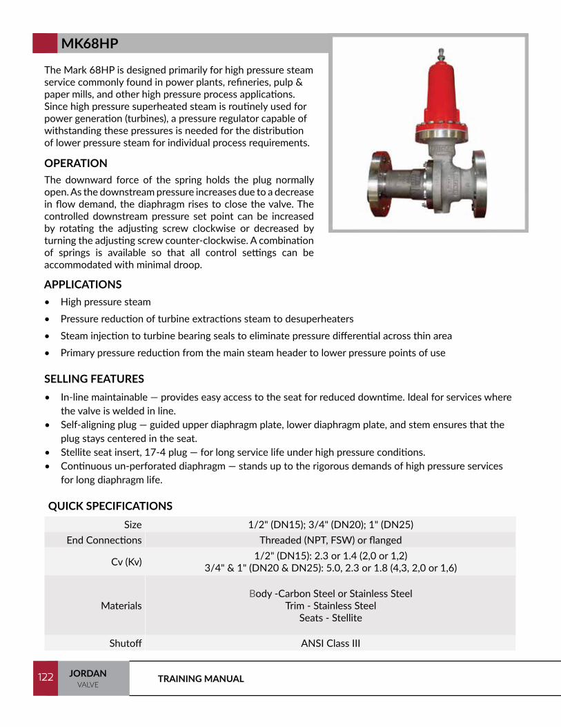
TRAINING MANUAL122 JORDANVALVE
122
The Mark 68HP is designed primarily for high pressure steam service commonly found in power plants, refineries, pulp & paper mills, and other high pressure process applications. Since high pressure superheated steam is routinely used for power generation (turbines), a pressure regulator capable of withstanding these pressures is needed for the distribution of lower pressure steam for individual process requirements.
OPERATIONThe downward force of the spring holds the plug normally open. As the downstream pressure increases due to a decrease in flow demand, the diaphragm rises to close the valve. The controlled downstream pressure set point can be increased by rotating the adjusting screw clockwise or decreased by turning the adjusting screw counter-clockwise. A combination of springs is available so that all control settings can be accommodated with minimal droop.
SELLING FEATURES• In-line maintainable — provides easy access to the seat for reduced downtime. Ideal for services where
the valve is welded in line.• Self-aligning plug — guided upper diaphragm plate, lower diaphragm plate, and stem ensures that the
plug stays centered in the seat.• Stellite seat insert, 17-4 plug — for long service life under high pressure conditions.• Continuous un-perforated diaphragm — stands up to the rigorous demands of high pressure services
for long diaphragm life.
APPLICATIONS• High pressure steam• Pressure reduction of turbine extractions steam to desuperheaters• Steam injection to turbine bearing seals to eliminate pressure differential across thin area• Primary pressure reduction from the main steam header to lower pressure points of use
QUICK SPECIFICATIONSSize 1/2" (DN15); 3/4" (DN20); 1" (DN25)
End Connections Threaded (NPT, FSW) or flanged
Cv (Kv) 1/2" (DN15): 2.3 or 1.4 (2,0 or 1,2)3/4" & 1" (DN20 & DN25): 5.0, 2.3 or 1.8 (4,3, 2,0 or 1,6)
MaterialsBody -Carbon Steel or Stainless Steel
Trim - Stainless SteelSeats - Stellite
Shutoff ANSI Class III
MK68HP
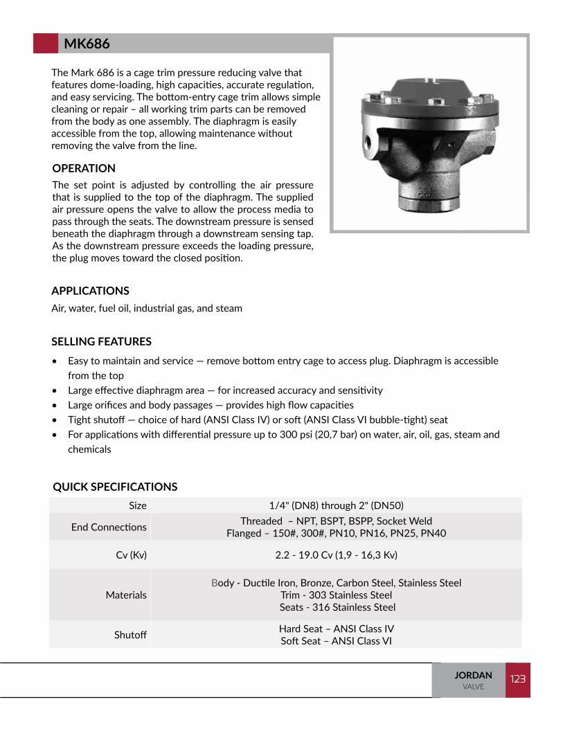
123JORDANVALVE
123
The Mark 686 is a cage trim pressure reducing valve that features dome-loading, high capacities, accurate regulation, and easy servicing. The bottom-entry cage trim allows simple cleaning or repair – all working trim parts can be removed from the body as one assembly. The diaphragm is easily accessible from the top, allowing maintenance without removing the valve from the line.
OPERATIONThe set point is adjusted by controlling the air pressure that is supplied to the top of the diaphragm. The supplied air pressure opens the valve to allow the process media to pass through the seats. The downstream pressure is sensed beneath the diaphragm through a downstream sensing tap. As the downstream pressure exceeds the loading pressure, the plug moves toward the closed position.
SELLING FEATURES• Easy to maintain and service — remove bottom entry cage to access plug. Diaphragm is accessible
from the top• Large effective diaphragm area — for increased accuracy and sensitivity• Large orifices and body passages — provides high flow capacities• Tight shutoff — choice of hard (ANSI Class IV) or soft (ANSI Class VI bubble-tight) seat• For applications with differential pressure up to 300 psi (20,7 bar) on water, air, oil, gas, steam and
chemicals
APPLICATIONSAir, water, fuel oil, industrial gas, and steam
QUICK SPECIFICATIONSSize 1/4" (DN8) through 2" (DN50)
End Connections Threaded – NPT, BSPT, BSPP, Socket WeldFlanged – 150#, 300#, PN10, PN16, PN25, PN40
Cv (Kv) 2.2 - 19.0 Cv (1,9 - 16,3 Kv)
MaterialsBody - Ductile Iron, Bronze, Carbon Steel, Stainless Steel
Trim - 303 Stainless Steel Seats - 316 Stainless Steel
Shutoff Hard Seat – ANSI Class IVSoft Seat – ANSI Class VI
MK686
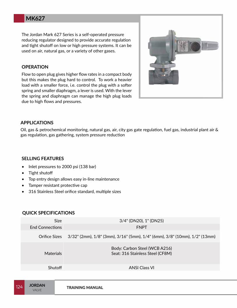
TRAINING MANUAL124 JORDANVALVE
124
The Jordan Mark 627 Series is a self-operated pressure reducing regulator designed to provide accurate regulation and tight shutoff on low or high pressure systems. It can be used on air, natural gas, or a variety of other gases.
OPERATIONFlow to open plug gives higher flow rates in a compact body but this makes the plug hard to control. To work a heavier load with a smaller force, i.e. control the plug with a softer spring and smaller diaphragm, a lever is used. With the lever the spring and diaphragm can manage the high plug loads due to high flows and pressures.
SELLING FEATURES• Inlet pressures to 2000 psi (138 bar)• Tight shutoff• Top entry design allows easy in-line maintenance• Tamper resistant protective cap• 316 Stainless Steel orifice standard, multiple sizes
APPLICATIONSOil, gas & petrochemical monitoring, natural gas, air, city gas gate regulation, fuel gas, industrial plant air & gas regulation, gas gathering, system pressure reduction
QUICK SPECIFICATIONSSize 3/4" (DN20), 1" (DN25)
End Connections FNPT
Orifice Sizes 3/32" (2mm), 1/8" (3mm), 3/16" (5mm), 1/4" (6mm), 3/8" (10mm), 1/2" (13mm)
MaterialsBody: Carbon Steel (WCB A216)Seat: 316 Stainless Steel (CF8M)
Shutoff ANSI Class VI
MK627

125JORDANVALVE
125
The Jordan Mark 630 self-operated pressure reducing regulator is designed to provide tight shutoff and accurate regulation on high pressure gas systems. It can be used on air and a variety of gases. It is designed to handle inlet pressures up to 1500 psi (103 bar).
OPERATIONFlow to open plug gives higher flow rates in a compact body but this makes the plug hard to control. To work a heavier load with a smaller force, i.e. control the plug with a softer spring and smaller diaphragm, a lever is used. With the lever, the spring and diaphragm can manage the high plug loads due to high flows and pressures.
SELLING FEATURES• Inlet pressures to 1500 psi (103 bar)• Tight shutoff• Easy maintenance• Rugged design• Multiple orifice sizes, stainless steel• NACE compatible
APPLICATIONSFirst cut or second stage regulator, high pressure process, fuel gas, natural gas, and air
QUICK SPECIFICATIONSSize 1" (DN25) through 2" (DN50)
End Connections FNPT *Contact factory for other options
Orifice Sizes 1/8" (3mm), 3/16" (5mm), 1/4" (6mm), 3/8" (10mm), 1/2" (13mm)
Materials Body: Ductile Iron, Carbon Steel (LLC)Seat: 316 Stainless Steel (CF8M)
Shutoff ANSI Class VI
MK630
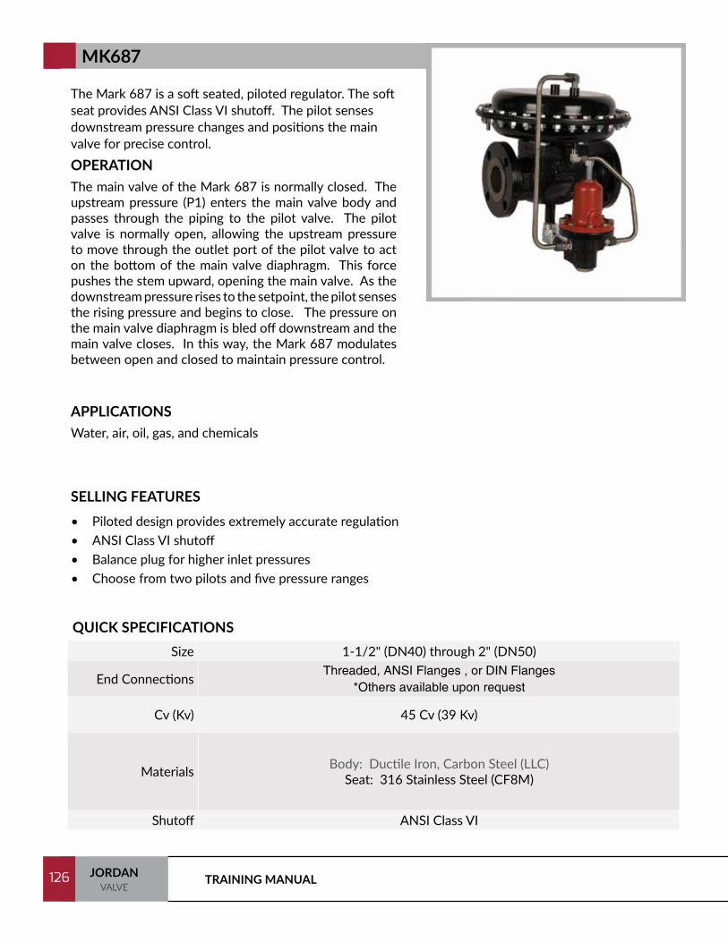
TRAINING MANUAL126 JORDANVALVE
126
The Mark 687 is a soft seated, piloted regulator. The soft seat provides ANSI Class VI shutoff. The pilot senses downstream pressure changes and positions the main valve for precise control.OPERATIONThe main valve of the Mark 687 is normally closed. The upstream pressure (P1) enters the main valve body and passes through the piping to the pilot valve. The pilot valve is normally open, allowing the upstream pressure to move through the outlet port of the pilot valve to act on the bottom of the main valve diaphragm. This force pushes the stem upward, opening the main valve. As the downstream pressure rises to the setpoint, the pilot senses the rising pressure and begins to close. The pressure on the main valve diaphragm is bled off downstream and the main valve closes. In this way, the Mark 687 modulates between open and closed to maintain pressure control.
SELLING FEATURES• Piloted design provides extremely accurate regulation• ANSI Class VI shutoff• Balance plug for higher inlet pressures• Choose from two pilots and five pressure ranges
APPLICATIONSWater, air, oil, gas, and chemicals
QUICK SPECIFICATIONSSize 1-1/2" (DN40) through 2" (DN50)
End ConnectionsThreaded, ANSI Flanges , or DIN Flanges
*Others available upon request
Cv (Kv) 45 Cv (39 Kv)
Materials Body: Ductile Iron, Carbon Steel (LLC)Seat: 316 Stainless Steel (CF8M)
Shutoff ANSI Class VI
MK687

127JORDANVALVE
127
The Mark 50 Sliding Gate Back Pressure Regulator is used to regulate upstream pressure at a predetermined setpoint. The spring in the Mark 50 holds the Sliding Gate seats in their normally closed position.
OPERATIONThe upstream pressure is sensed beneath the diaphragm. (A sensing line is required on sizes: 2-1/2", 3", and 4"). As the upstream pressure exceeds the setpoint, pressure is exerted on the diaphragm which raises the stem to modulate the disc (the movable component of the Sliding Gate seat set) toward the open position. As the seats open, upstream pressure will be regulated to the required setpoint. A decrease in pressure relaxes the spring and diaphragm to move the seats toward the closed position.
SELLING FEATURES• Straight-through Flow
• Sliding Gate Seat — unique seat design for unsurpassed trim life and accuracy.
• Jorlon Diaphragm — extremely durable, virtually universally applicable up to 450°F (232°C).
• Quiet Operation — typically 5-10 dB less than conventional globe style regulators. The disc and plate are always in contact, which eliminates chattering. *Straight-through flow minimizes turbulence. Multiple orifices in the plate and disc divide the flow stream into smaller flow components.
• Minimum Maintenance — The MK50 Sliding Gate seats require no special tools for disassembly.
• MK51 Extra Sensitive — Achieves greater accuracy and sensitivity via an oversized elastomer diaphragm
APPLICATIONSSteam, water, oil, gas, air, and chemicals
QUICK SPECIFICATIONSSize 1/4" (DN8) through 4" (DN100)
End Connections Threaded, ANSI, DIN, or JIS Flanged
Cv (Kv) 0.84 - 200 Cv (0,74 - 172 Kv)
Materials
Body - Ductile Iron, Bronze, Carbon Steel, Stainless SteelTrim - 303SST or 316SST
Seats -Jorcote on SST**Other Materials Available
Shutoff ANSI Class IV
MK50
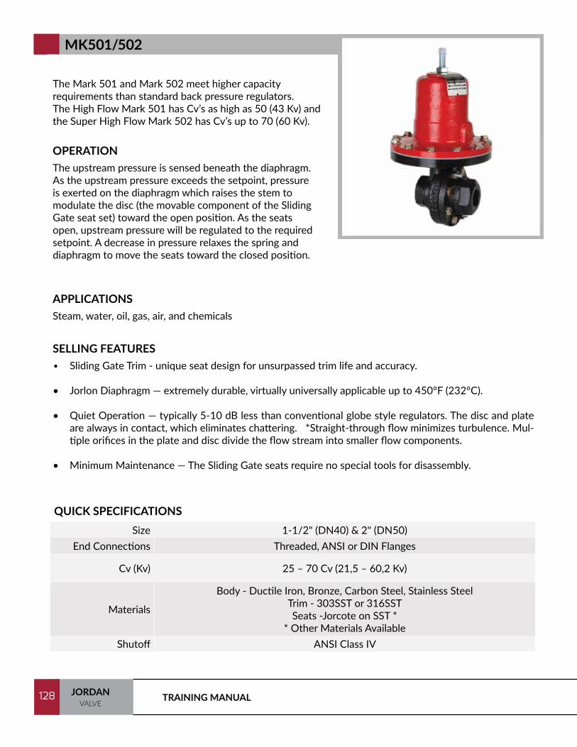
TRAINING MANUAL128 JORDANVALVE
128
The Mark 501 and Mark 502 meet higher capacity requirements than standard back pressure regulators.The High Flow Mark 501 has Cv’s as high as 50 (43 Kv) and the Super High Flow Mark 502 has Cv’s up to 70 (60 Kv).
OPERATIONThe upstream pressure is sensed beneath the diaphragm. As the upstream pressure exceeds the setpoint, pressure is exerted on the diaphragm which raises the stem to modulate the disc (the movable component of the Sliding Gate seat set) toward the open position. As the seats open, upstream pressure will be regulated to the required setpoint. A decrease in pressure relaxes the spring and diaphragm to move the seats toward the closed position.
APPLICATIONSSteam, water, oil, gas, air, and chemicals
QUICK SPECIFICATIONSSize 1-1/2" (DN40) & 2" (DN50)
End Connections Threaded, ANSI or DIN Flanges
Cv (Kv) 25 – 70 Cv (21,5 – 60,2 Kv)
Materials
Body - Ductile Iron, Bronze, Carbon Steel, Stainless SteelTrim - 303SST or 316SSTSeats -Jorcote on SST *
* Other Materials AvailableShutoff ANSI Class IV
MK501/502
SELLING FEATURES• Sliding Gate Trim - unique seat design for unsurpassed trim life and accuracy.
• Jorlon Diaphragm — extremely durable, virtually universally applicable up to 450°F (232°C).
• Quiet Operation — typically 5-10 dB less than conventional globe style regulators. The disc and plate are always in contact, which eliminates chattering. *Straight-through flow minimizes turbulence. Mul-tiple orifices in the plate and disc divide the flow stream into smaller flow components.
• Minimum Maintenance — The Sliding Gate seats require no special tools for disassembly.

129JORDANVALVE
129
The Mark 52 internally piloted back pressure regulator is a specialty valve designed for critical application regulation in locations where space is limited. Small and lightweight in design, the MK52 valve provides the accuracy of a piloted valve with the size, weight and appearance of a single, self-operated valve. As the Mark 52 is self operating, it is suitable for use in locations where accurate regulation is needed, but air or electric supply may not be readily available.
OPERATIONThe operation of the Mark 52 is very similar to that of an externally piloted regulator. The main valve and the pilot are normally closed. The inlet pressure passes through the inlet pilot tubing beneath the pilot diaphragm. When the set point is reached, the force of the adjusting spring is overcome, and the pilot valve opens. This allows the inlet pressure to enter the chamber above the main diaphragm and opens the main valve. When the pressure drops below the set point, the adjusting spring overcomes the force of the pressure beneath the pilot diaphragm and the pilot and main valve closes.
SELLING FEATURES• Internal pilot — provides highly accurate performance in a compact, lightweight assembly.• Sliding Gate Seats — all of Jordan Valve’s piloted back pressure regulators feature advanced Sliding Gate
seat technology.
— Straight-through flow for reduced turbulence and quiet operation— Short stroke for fast response and accurate regulation.— Easily interchangeable Cv’s— Tight Shutoff
APPLICATIONSClean gas, steam, and air
QUICK SPECIFICATIONSSize 1/2" (DN15) through 2" (DN50)
End Connections Threaded or Flanged
Cv (Kv) 2.5 to 30 Cv (2,15 - 25,8 Kv)
Materials
Body - Ductile Iron or Bronze Trim - Stainless Steel or 316SST
Seats - Jorlon, Jorcote/Jordanic , and Chrome Plated SST**Other Materials Available
Shutoff ANSI Class IV
MK52

TRAINING MANUAL130 JORDANVALVE
130
The Jordan Mark 53 maintains a constant differential between the inlet pressure and the pressure loaded on top of the diaphragm. It can be used for both differential and remotely adjusted applications. The Mark 54 provides the same flow capacity as the Mark 53 but with less offset in controlled pressure due to the larger diaphragm.
OPERATIONThe valve is normally closed. The inlet pressure acts beneath the diaphragm and is opposed by the force of the adjusting spring plus the pressure of the loading fluid. As the inlet pressure overcomes the set point (the combined pressures on top of the diaphragm), the valve moves toward the open position, relieving the necessary pressure to maintain the set point.
SELLING FEATURES• Mark 53/54 — maintains a constant differential between the inlet pressure and the pressure loaded to
the top of the diaphragm.• Sliding Gate Seats — all of Jordan Valve’s differential regulators feature advanced Sliding Gate seat
technology. — Straight-through flow for reduced turbulence and quiet operation — Short stroke for fast response and accurate regulation — Easily interchangeable Cv’s — Tight Shutoff
APPLICATIONSSteam, water, oil, air, and chemicals
QUICK SPECIFICATIONS
Size MK53: 1/4" (DN8) through 2" (DN50) MK54: 1/4" (DN8) through 3/4" (DN20)
End Connections Threaded, ANSI flanged, or DIN flanged
Cv (Kv) 0.84 - 30 Cv (0,74 - 26 Kv)
MaterialsBody - Ductile Iron, Bronze, Carbon Steel, or Stainless Steel
Trim - 303SST or 316SSTSeats - Jorlon, Jorcote/Jordanic , and Chrome Plated SST
Shutoff ANSI Class IV
MK53/54
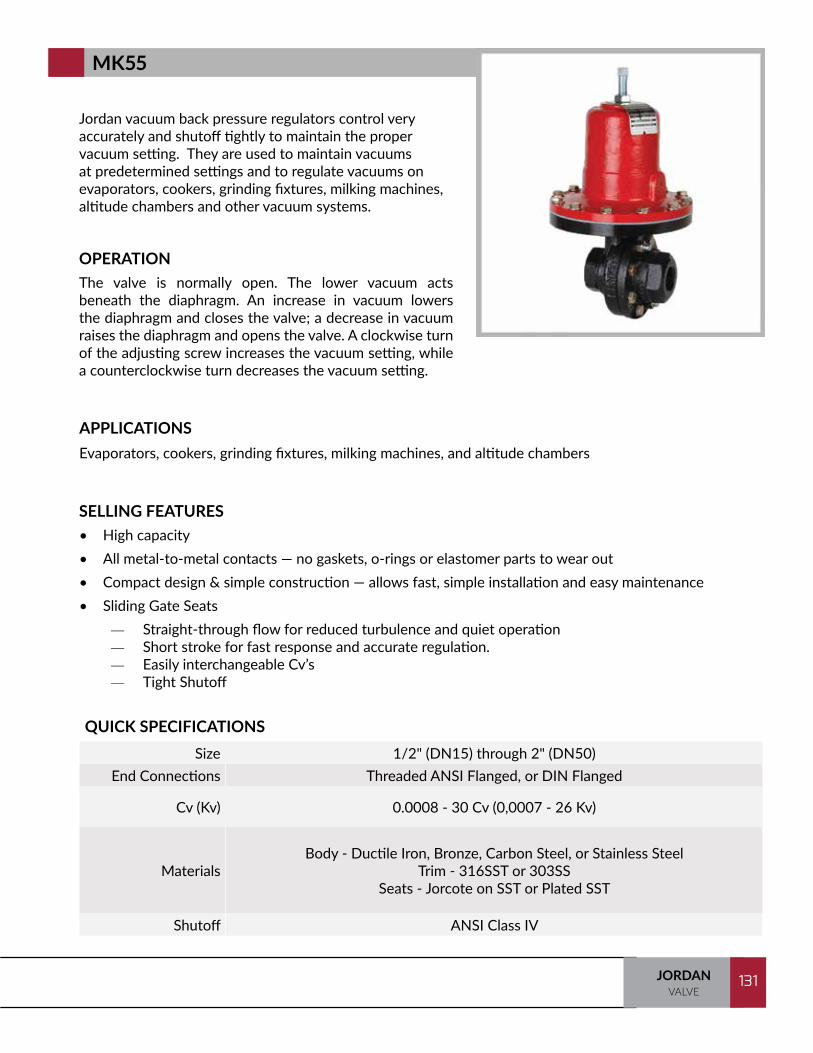
131JORDANVALVE
131
Jordan vacuum back pressure regulators control very accurately and shutoff tightly to maintain the proper vacuum setting. They are used to maintain vacuums at predetermined settings and to regulate vacuums on evaporators, cookers, grinding fixtures, milking machines, altitude chambers and other vacuum systems.
OPERATIONThe valve is normally open. The lower vacuum acts beneath the diaphragm. An increase in vacuum lowers the diaphragm and closes the valve; a decrease in vacuum raises the diaphragm and opens the valve. A clockwise turn of the adjusting screw increases the vacuum setting, while a counterclockwise turn decreases the vacuum setting.
SELLING FEATURES• High capacity• All metal-to-metal contacts — no gaskets, o-rings or elastomer parts to wear out• Compact design & simple construction — allows fast, simple installation and easy maintenance• Sliding Gate Seats
— Straight-through flow for reduced turbulence and quiet operation— Short stroke for fast response and accurate regulation.— Easily interchangeable Cv’s— Tight Shutoff
APPLICATIONSEvaporators, cookers, grinding fixtures, milking machines, and altitude chambers
QUICK SPECIFICATIONSSize 1/2" (DN15) through 2" (DN50)
End Connections Threaded ANSI Flanged, or DIN Flanged
Cv (Kv) 0.0008 - 30 Cv (0,0007 - 26 Kv)
MaterialsBody - Ductile Iron, Bronze, Carbon Steel, or Stainless Steel
Trim - 316SST or 303SSSeats - Jorcote on SST or Plated SST
Shutoff ANSI Class IV
MK55

TRAINING MANUAL132 JORDANVALVE
132
The dome loaded MK56 offers an easily adjustable setpoint. The setpoint is based on changing the air load to the top of the main valve’s diaphragm. Because of this, it is often found in applications in which the pressure it controls must be changed to differing setpoints during the manufacturing process. The maximum setpoint is equal to the maximum body pressure limit.
OPERATIONThe inlet pressure setting is adjusted by controlling the air pressure supplied to the top of the diaphragm. The valve disc is normally stroked up, opening the valve. Air pressure supplied to the top of the diaphragm closes the valve. As the inlet pressure begins to balance the loading pressure, the return spring moves the seats toward the open position. To increase the controlled pressure, increase the air to the top of the diaphragm. Sensing line required on 2 1/2" or higher.
SELLING FEATURES• Highly accurate• High rangeability • All metal-to-metal contacts – no gaskets or o-rings to wear out (2"/DN50 and under)• Versatile application – use on steam, air, gas, liquids or chemicals• Sliding Gate Seats — Straight-through flow for reduced turbulence and quiet operation — Short stroke for fast response and accurate regulation — Easily interchangeable Cv’s — Tight Shutoff
APPLICATIONSSteam, water, air, gas, oil, chemicals
QUICK SPECIFICATIONSSize 1/2" (DN15) through 6" (DN150)
End Connections Threaded, ANSI flanged, DIN flanged, or JIS Flanged
Cv (Kv) 2.5 - 395 Cv (2,2 - 340 Kv)
MaterialsBody - Ductile Iron, Bronze, Carbon Steel, Stainless Steel, or Cast Iron
Trim - 303SS, 316SS, Jorcote/Jordanic, and Chrome Plated SSTSeats - Jorcote on SST, Jordanic on SST, and Chrome Plated SST
Shutoff ANSI Class IV
MK56
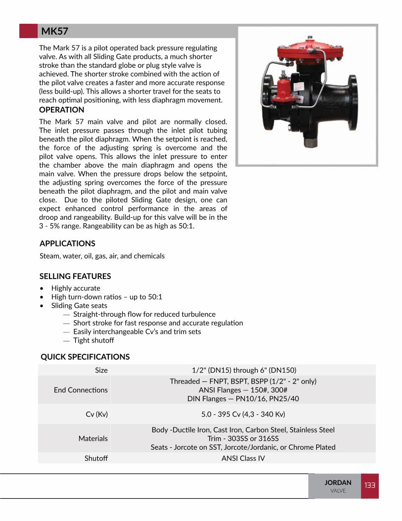
133JORDANVALVE
133
The Mark 57 is a pilot operated back pressure regulating valve. As with all Sliding Gate products, a much shorter stroke than the standard globe or plug style valve is achieved. The shorter stroke combined with the action of the pilot valve creates a faster and more accurate response (less build-up). This allows a shorter travel for the seats to reach optimal positioning, with less diaphragm movement.OPERATIONThe Mark 57 main valve and pilot are normally closed. The inlet pressure passes through the inlet pilot tubing beneath the pilot diaphragm. When the setpoint is reached, the force of the adjusting spring is overcome and the pilot valve opens. This allows the inlet pressure to enter the chamber above the main diaphragm and opens the main valve. When the pressure drops below the setpoint, the adjusting spring overcomes the force of the pressure beneath the pilot diaphragm, and the pilot and main valve close. Due to the piloted Sliding Gate design, one can expect enhanced control performance in the areas of droop and rangeability. Build-up for this valve will be in the 3 - 5% range. Rangeability can be as high as 50:1.
SELLING FEATURES• Highly accurate • High turn-down ratios – up to 50:1• Sliding Gate seats — Straight-through flow for reduced turbulence — Short stroke for fast response and accurate regulation — Easily interchangeable Cv’s and trim sets — Tight shutoff
APPLICATIONSSteam, water, oil, gas, air, and chemicals
QUICK SPECIFICATIONSSize 1/2" (DN15) through 6" (DN150)
End ConnectionsThreaded — FNPT, BSPT, BSPP (1/2" - 2" only)
ANSI Flanges — 150#, 300#DIN Flanges — PN10/16, PN25/40
Cv (Kv) 5.0 - 395 Cv (4,3 - 340 Kv)
MaterialsBody -Ductile Iron, Cast Iron, Carbon Steel, Stainless Steel
Trim - 303SS or 316SSSeats - Jorcote on SST, Jorcote/Jordanic, or Chrome Plated
Shutoff ANSI Class IV
MK57

TRAINING MANUAL134 JORDANVALVE
134
The Mark 58 is a cage trim back pressure regulator featuring three ports: a bypass outlet on the bottom, and two side ports which are directly connected to serve as inlet and outlet for through-flow. The Mark 58 is available in sizes up to 2" (DN50) in a wide variety of body materials. Diaphragms can be either Stainless Steel or elastomer. Low flow versions with Cv values as low as 0.26 (2,24 Kv) are available in certain sizes.
OPERATIONThe Mark 58 back pressure regulator features three ports: a bypass outlet on the bottom and two side ports which are directly connected to serve as inlet and outlet for flow-through. It can be installed in a "T" fashion (MK58FT) allowing fluid to flow in one side and out the other with the flow relieved via the bottom bypass when the pressure exceeds the setting. It can also be installed with one side port as an inlet and the other side port plugged (MK58A). In this arrangement, when the inlet pressure exceeds the set point, fluid is relieved through the bottom port.
SELLING FEATURES• Easy maintenance – cage can be removed from the bottom port to access plug; diaphragm is
accessible from top• Highly accurate – large effective diaphragm area reduces droop• High flow capacities• Tight shutoff – ANSI Class IV (hard seats) or ANSI Class VI (soft seats)
APPLICATIONSWater, air, oil, gas, steam, chemicals
QUICK SPECIFICATIONSSize 1/2" (DN8) through 2" (DN50)
End Connections Threaded, ANSI Flanged, or DIN Flanged
Cv (Kv) 2.2 - 13.5 Cv (1,9 - 11,6 Kv)
MaterialsBody - Ductile Iron, Bronze, Carbon Steel, Stainless Steel
Hard Seat Plug - 17-4 plug with EPDM, 17-4 plug with VitonSoft Seat Plug - Buna-N / 316, Viton / 316, EPDM / 316
Shutoff Hard Seat – ANSI Class IVSoft Seat – ANSI Class VI
MK58FT/58A
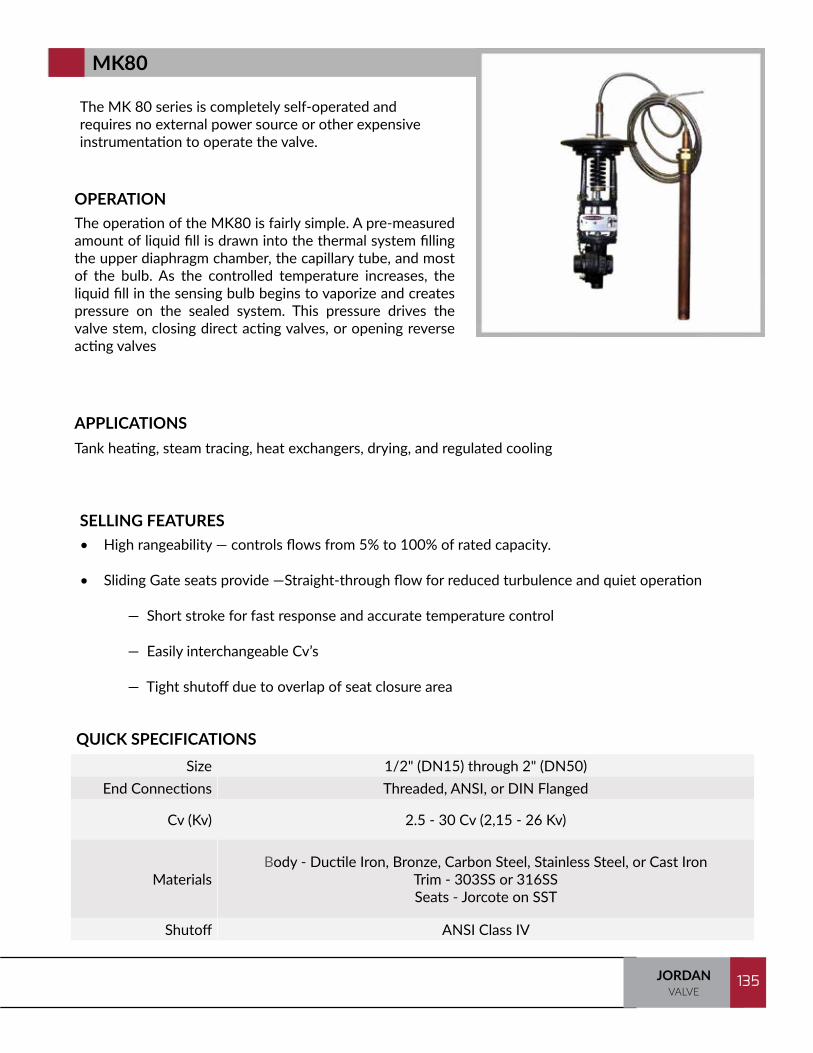
135JORDANVALVE
135
The MK 80 series is completely self-operated and requires no external power source or other expensive instrumentation to operate the valve.
OPERATIONThe operation of the MK80 is fairly simple. A pre-measured amount of liquid fill is drawn into the thermal system filling the upper diaphragm chamber, the capillary tube, and most of the bulb. As the controlled temperature increases, the liquid fill in the sensing bulb begins to vaporize and creates pressure on the sealed system. This pressure drives the valve stem, closing direct acting valves, or opening reverse acting valves
SELLING FEATURES• High rangeability — controls flows from 5% to 100% of rated capacity.
• Sliding Gate seats provide —Straight-through flow for reduced turbulence and quiet operation
— Short stroke for fast response and accurate temperature control
— Easily interchangeable Cv’s
— Tight shutoff due to overlap of seat closure area
APPLICATIONSTank heating, steam tracing, heat exchangers, drying, and regulated cooling
QUICK SPECIFICATIONSSize 1/2" (DN15) through 2" (DN50)
End Connections Threaded, ANSI, or DIN Flanged
Cv (Kv) 2.5 - 30 Cv (2,15 - 26 Kv)
MaterialsBody - Ductile Iron, Bronze, Carbon Steel, Stainless Steel, or Cast Iron
Trim - 303SS or 316SSSeats - Jorcote on SST
Shutoff ANSI Class IV
MK80

TRAINING MANUAL136 JORDANVALVE
136
The Mark 801 and 802 series provide extremely high flows, are completely self-operated and require no external power source or other expensive instrumentation to operate the valve.
OPERATIONThe operation of the MK801 and 802 Series is fairly simple. A pre-measured amount of liquid fill is drawn into the thermal system filling the upper diaphragm chamber, the capillary tube, and most of the bulb. As the controlled temperature increases, the liquid fill in the sensing bulb begins to vaporize and creates pressure on the sealed system. This pressure drives the valve stem, closing direct acting valves, or opening reverse acting valves.
SELLING FEATURES• SWA actuator• Custom capillary lengths • Sliding Gate seats provides: — Straight-through flow for reduced turbulence and quiet operation — Short stroke for fast response and accurate temperature control — Easily interchangeable Cv’s — Tight shutoff due to overlap of seat closure area
APPLICATIONSTank heating, steam tracing, heat exchangers, drying, and regulated cooling
QUICK SPECIFICATIONSSize 1/2" through 2" (DN15 through DN50)
End Connections Threaded, ANSI or DIN Flanges
Cv (Kv) 6.4 – 70 Cv (5,5 – 60 Kv)
Materials
Body - Ductile Iron, Bronze, Carbon Steel, Stainless SteelTrim - 303SST or 316SSTSeats -Jorcote on SST *
* Other Materials AvailableShutoff ANSI Class IV
MK801/802

137JORDANVALVE
137
The MK82 internally piloted valve provides fast response, bet-ter rangeability, higher accuracy, and shorter bulbs than can be found with the MK80. Whereas, our MK80 has a span between span between 10°F and 15°F, the MK82’s span is just 4°F. This valve should be used anywhere precise control is required.
OPERATIONThe internal pilot valve seats and the main valve seats are up and closed. As the process temperature rises, the fluid in the sensing bulb vaporizes to apply pressure to the pilot diaphragm, thus opening the pilot valve. The upstream pressure passes through the pilot valve, through the pilot port opening the main valve to provide the required cooling action.
As the temperature sensed at the bulb drops, the pilot valve tends to close, shutting off pressure to the main valve’s diaphragm. The lower spring closes the main valve as the pressure on the main diaphragm is bled off through the downstream port.
Direct Acting MK82 – operates as above except that the pilot valve is normally open and closes on an increase in temperature.
SELLING FEATURES
• Extremely accurate• Sliding Gate Seats — Straight-through flow for reduced turbulence, longer life and quiet operation — Short stroke for fast response and accurate regulation — Easily interchangeable Cv’s — Extended tight shutoff due to wear resistant coatings and overlap of seat closure area
APPLICATIONSSmall, well insulated tanks or chambers. Clean service only.
QUICK SPECIFICATIONSSize 1/2" (DN15) through 2" (DN50)
End Connections Threaded or Flanged
Cv (Kv) 2.5 to 30 Cv (2,15 - 26 Kv)
MaterialsBody - Ductile Iron or Bronze
Trim - Stainless Steel or Bronze Seats - Jorcote or Chrome Platted
Shutoff ANSI Class IV
MK82

TRAINING MANUAL138 JORDANVALVE
138
The Mark 85 is a self-operated temperature regulator with controlled failure option which allows you to predetermine the position of the valve in the event of a thermal system failure. The Mark 85 is designed to fail closed on heating applications and to fail open on cooling applications.
OPERATIONThe direct acting Mark 85 is normally open, held in this position by a vacuum in the thermal system. As the process temperature increases, the vacuum decreases, allowing the spring to pull the diaphragm downward to close the seats. A leak in the thermal system will again decrease the vacuum and cause the seats to close.
An inherent feature of the controlled failure design is that it is slower responding than a standard temperature regulator and cannot compensate as quickly for rapid load changes. It is ideal for slower responding systems such as autoclaves and large storage tanks.
SELLING FEATURES• Replaceable thermal system• Sliding Gate Seats — Straight-through flow for reduced turbulence and quiet operation — Short stroke for fast response and accurate regulation — Easily interchangeable Cv’s — Tight shutoff due to overlap of seat closure area
APPLICATIONSSlower responding systems, autoclaves, large storage tanks
QUICK SPECIFICATIONSSize 1/2" (DN15) and 3/4" (DN20)
End Connections Threaded or Flanged
Cv (Kv) 0.84 - 4.4 Cv (0,7 - 3,8 Kv)
MaterialsBody - Ductile Iron, Bronze, Carbon Steel, Stainless Steel, or Cast Iron
Trim - 303SS or 316SSSeats - Jorcote or Chrome Platted
Shutoff ANSI Class IV
MK85

139JORDANVALVE
139
The Mark 86 temperature regulator is designed to control steam tracing lines based on ambient temperatures. These steam tracing lines are commonly used to protect outdoor instrumentation, pipelines and tanks from freezing. The Mark 86 allows steam to flow through the tracer lines only when it is needed, and remains closed when the ambient temperature rises above a predetermined set point.
OPERATIONThe Mark 86 is generally installed as a normally closed valve. As the ambient temperature falls below the set point, the valve will open, allowing steam to enter the tracing line system. The Mark 86 may also be set up as a normally open valve and stroke toward closed as the ambient temperature rises.
SELLING FEATURES
• Sealed Welded Actuator – no elastomer parts providing longer service life• Sliding Gate Seats — Straight-through flow for reduced turbulence and quiet operation — Short stroke for fast response and accurate regulation — Easily interchangeable Cv’s — Tight shutoff
APPLICATIONSSteam tracing for outdoor instrumentation, pipelines, and tanks
QUICK SPECIFICATIONSSize 1/2" (DN15) through 2" (DN50)
End Connections Threaded, ANSI Flanged, DIN Flanged, or JIS Flanged
Cv (Kv) 02.5 - 30 Cv (2,15 - 26 Kv)
MaterialsBody - Ductile Iron, Bronze, Carbon Steel, Stainless Steel, or Cast Iron
Trim - 316SST and Stainless SteelSeats - Jorcote on SST and Chrome Plated SST
Shutoff ANSI Class IV
MK86
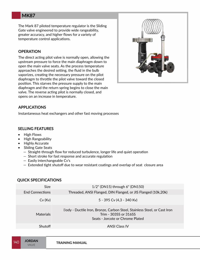
TRAINING MANUAL140 JORDANVALVE
140
The Mark 87 piloted temperature regulator is the Sliding Gate valve engineered to provide wide rangeability, greater accuracy, and higher flows for a variety of temperature control applications.
OPERATIONThe direct acting pilot valve is normally open, allowing the upstream pressure to force the main diaphragm down to open the main valve seats. As the process temperature approaches the desired setting, the fluid in the bulb vaporizes, creating the necessary pressure on the pilot diaphragm to throttle the pilot valve toward the closed position. This starves the pressure supply to the main diaphragm and the return spring begins to close the main valve. The reverse acting pilot is normally closed, and opens on an increase in temperature.
SELLING FEATURES• High Flows• High Rangeability • Highly Accurate • Sliding Gate Seats — Straight-through flow for reduced turbulence, longer life and quiet operation — Short stroke for fast response and accurate regulation — Easily interchangeable Cv’s — Extended tight shutoff due to wear resistant coatings and overlap of seat closure area
APPLICATIONSInstantaneous heat exchangers and other fast moving processes
QUICK SPECIFICATIONSSize 1/2" (DN15) through 6" (DN150)
End Connections Threaded, ANSI Flanged, DIN Flanged, or JIS Flanged (10k,20k)
Cv (Kv) 5 - 395 Cv (4,3 - 340 Kv)
MaterialsBody - Ductile Iron, Bronze, Carbon Steel, Stainless Steel, or Cast Iron
Trim - 303SS or 316SSSeats - Jorcote or Chrome Plated
Shutoff ANSI Class IV
MK87

141JORDANVALVE
141
The Mark 89 is a three-way, self-contained temperature regulating valve for use on diverting service (MK89) or for combining fluids as a mixing valve (MK89MX).
OPERATIONThe MK89 is used for diverting service and is ideal for bypassing fluids around coolers or filters. In this configuration, there is one inlet and two outlet ports. When one seat is opened, or opening, the other is closed or closing. The MK89X is used for mixing and in this configuration two inlets and one outlet are required.
SELLING FEATURES• Highly accurate• Completely self-operated — no external power source required.• Totally enclosed, heliarc welded stainless steel actuator for long service life — no gaskets or bellows to
wear out.• Thermal system with capillaries up to 100 feet (30 meters) in length are easily replaced in the field for
quick range changes.• Sliding Gate seats provide — — Straight-through flow for reduced turbulence and quiet operation — Short stroke for fast response and accurate temperature control — Easily interchangeable Cv’s — Tight shutoff
APPLICATIONSDiverting, mixing, steam, water, oil, gas, air and chemicals
QUICK SPECIFICATIONSSize 1-1/2" (DN40) and 2" (DN50)
End Connections NPT, BSPT, BSPP, Flanged
Cv (Kv) 15 - 30 Cv (12,9 - 26 Kv)
MaterialsBody - Carbon Steel or Stainless Steel
Trim - 303SS or 316SSSeats - Jorcote or Chrome Plated
Shutoff ANSI Class IV
MK89/89MX
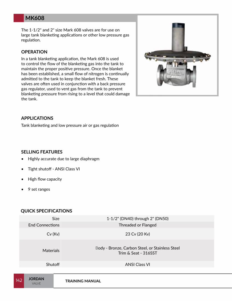
TRAINING MANUAL142 JORDANVALVE
142
The 1-1/2" and 2" size Mark 608 valves are for use on large tank blanketing applications or other low pressure gas regulation.
OPERATIONIn a tank blanketing application, the Mark 608 is used to control the flow of the blanketing gas into the tank to maintain the proper positive pressure. Once the blanket has been established, a small flow of nitrogen is continually admitted to the tank to keep the blanket fresh. These valves are often used in conjunction with a back pressure gas regulator, used to vent gas from the tank to prevent blanketing pressure from rising to a level that could damage the tank.
SELLING FEATURES• Highly accurate due to large diaphragm
• Tight shutoff - ANSI Class VI
• High flow capacity
• 9 set ranges
APPLICATIONSTank blanketing and low pressure air or gas regulation
QUICK SPECIFICATIONSSize 1-1/2" (DN40) through 2" (DN50)
End Connections Threaded or Flanged
Cv (Kv) 23 Cv (20 Kv)
Materials Body - Bronze, Carbon Steel, or Stainless SteelTrim & Seat - 316SST
Shutoff ANSI Class VI
MK608
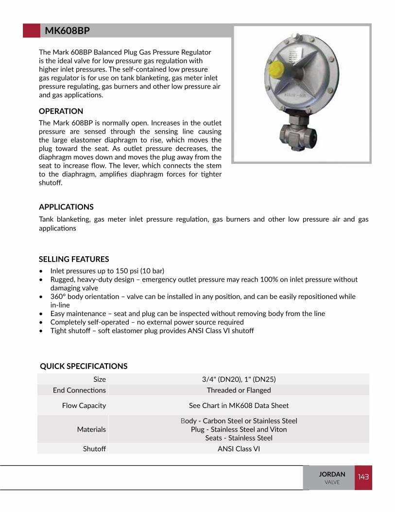
143JORDANVALVE
143
The Mark 608BP Balanced Plug Gas Pressure Regulator is the ideal valve for low pressure gas regulation with higher inlet pressures. The self-contained low pressure gas regulator is for use on tank blanketing, gas meter inlet pressure regulating, gas burners and other low pressure air and gas applications.
OPERATIONThe Mark 608BP is normally open. Increases in the outlet pressure are sensed through the sensing line causing the large elastomer diaphragm to rise, which moves the plug toward the seat. As outlet pressure decreases, the diaphragm moves down and moves the plug away from the seat to increase flow. The lever, which connects the stem to the diaphragm, amplifies diaphragm forces for tighter shutoff.
SELLING FEATURES• Inlet pressures up to 150 psi (10 bar)• Rugged, heavy-duty design – emergency outlet pressure may reach 100% on inlet pressure without
damaging valve• 360° body orientation – valve can be installed in any position, and can be easily repositioned while
in-line• Easy maintenance – seat and plug can be inspected without removing body from the line• Completely self-operated – no external power source required• Tight shutoff – soft elastomer plug provides ANSI Class VI shutoff
APPLICATIONSTank blanketing, gas meter inlet pressure regulation, gas burners and other low pressure air and gas applications
QUICK SPECIFICATIONSSize 3/4" (DN20), 1" (DN25)
End Connections Threaded or Flanged
Flow Capacity See Chart in MK608 Data Sheet
MaterialsBody - Carbon Steel or Stainless Steel
Plug - Stainless Steel and Viton Seats - Stainless Steel
Shutoff ANSI Class VI
MK608BP

TRAINING MANUAL144 JORDANVALVE
144
The Mark 608DS is a double seated, self-operated gas regulator for use in tank blanketing applications. The double seated design allows the Mark 608DS to handle increased flow and higher pressure drops than similarly sized single seat valve types while maintaining ANSI Class VI shutoff.
OPERATIONThe Mark 608DS is used to control the flow of the blanketing gas into the tank to maintain the proper positive pressure. Increases in the outlet pressure are sensed through the sensing line causing the large elastomer diaphragm to rise, which moves the plugs toward their seats. As outlet pressure decreases, the diaphragm moves down and moves the plug away from the seat to increase flow.
SELLING FEATURES• Large, highly sensitive diaphragm insures accurate regulation
• Tight shutoff - ANSI Class VI
• High capacity
APPLICATIONSTank blanketing and other gas applications
QUICK SPECIFICATIONSSize 1-1/2" (DN40) through 2" (DN50)
End Connections ANSI Flanged
Cv (Kv) 1-1/2" size: 5 Cv; orifice 9/16" (14mm) 2" size: 17 Cv; orifice 1" (26mm)
MaterialsBody - Carbon Steel or Stainless Steel
Trim- Stainless Steel or Hasteloy CSeats - To match diaphragm
Shutoff ANSI Class VI
MK608DS

145JORDANVALVE
145
The Mark 608IS gas pressure regulator is the ideal valve for low pressure gas regulation. The self-contained low pressure gas regulator is for use on tank blanketing, gas meter inlet pressure regulating, gas burners and other low pressure air and gas applications.
OPERATIONThe Mark 608 is normally open. Increases in the outlet pressure are sensed through the aspirator causing the large elastomer diaphragm to rise, which moves the plug toward the seat. As outlet pressure decreases, the diaphragm moves down and moves the plug away from the seat to increase flow. The lever, which connects the stem to the diaphragm, amplifies diaphragm forces for tighter shutoff.
SELLING FEATURES• Inlet pressures up to 150 psi (10 bar)• Rugged, heavy-duty design – emergency outlet pressure may reach 100% on inlet pressure without
damaging valve• 360° body orientation – valve can be installed in any position and can be easily repositioned while
in-line• Easy maintenance – seat and plug can be inspected without removing body from the line• Completely self-operated – no external power source required• Tight shutoff – soft elastomer plug provides ANSI Class VI shutoff
APPLICATIONSTank blanketing, gas meter inlet pressure regulating, gas burners, and low pressure air and gas applications
QUICK SPECIFICATIONSSize 3/4" (DN20), 1" (DN25), 1-1/4" (DN32)
End Connections Threaded or Flanged
Flow Capacity See Chart in MK608IS Datasheet
MaterialsBody - Carbon Steel or Stainless Steel
Plug- Stainless Steel and Viton Seats - Stainless Steel
Shutoff ANSI Class VI
MK608IS

TRAINING MANUAL146 JORDANVALVE
146
The Mark 688 Series piloted soft seat regulator was designed specifically to provide accurate pressure control on very low pressure tank blanketing systems. The pilot operated Mark 688 responds to very small changes in tank pressure by throttling open or closed to maintain the desired pressure set point.
OPERATIONSee following page
SELLING FEATURES• Accurate regulation down to 1" wc (2.49 mbar)• ANSI Class VI Shutoff• Five available spring ranges • 200 psi maximum inlet pressure• High flows: Cv 1" - 17; 1-1/2" - 30; 2" - 45
APPLICATIONSTank blanketing
QUICK SPECIFICATIONSSize 1" (DN25) through 2" (DN50)
End Connections ANSI Flanges
Cv (Kv) 17-45 Cv (14,7 - 38,9 Kv)
MaterialsBody - Carbon Steel, Stainless Steel
Trim - 316 Stainless Steel Seats - 316 Stainless Steel/Viton
Shutoff ANSI Class VI
MK688

147JORDANVALVE
147
OPERATIONInlet pressure (P1) is applied to the upstream piping of the product and fed into the Mark 68G conditioning regulator. The main valve is normally closed and the conditioning regulator is normally open. The conditioning regulator reduces the inlet pressure (P1’) before it goes to the Mark 608P pilot valve. The tank pressure (P2) is sensed through a control line from the vessel to the main valve actuator and is simultaneously fed to the pilot. When tank pressure decreases below the set point, the pilot will sense a drop in P2 and spring force on the pilot diaphragm opens the pilot valve plug, allowing additional loading pressure to the main valve actuator diaphragm. The loading pressure opens the main valve plug to supply the required flow of gas (P2’) to the tank. When downstream demand has been satisfied, tank pressure (P2) increases and acts on the pilot and main valve diaphragms. When the sensed pressure (P2) exceeds the pilot control spring setting, the pilot diaphragm moves to close the pilot valve plug. The loading pressure (P3) reduces by exhausting downstream through the bleed orifice (P4), allowing the main valve spring to close the main valve plug.
P2 Tank Pressure
P3
Outlet P2'
P1P1'
P4
Bleed Orifice
Inlet P1
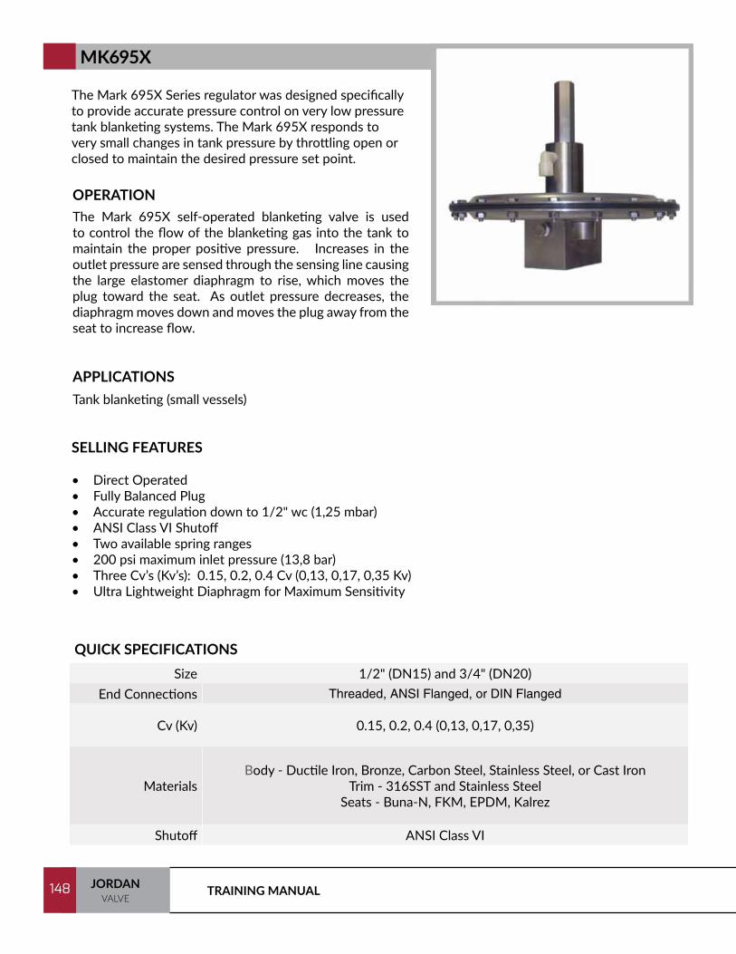
TRAINING MANUAL148 JORDANVALVE
148
The Mark 695X Series regulator was designed specifically to provide accurate pressure control on very low pressure tank blanketing systems. The Mark 695X responds to very small changes in tank pressure by throttling open or closed to maintain the desired pressure set point.
OPERATIONThe Mark 695X self-operated blanketing valve is used to control the flow of the blanketing gas into the tank to maintain the proper positive pressure. Increases in the outlet pressure are sensed through the sensing line causing the large elastomer diaphragm to rise, which moves the plug toward the seat. As outlet pressure decreases, the diaphragm moves down and moves the plug away from the seat to increase flow.
SELLING FEATURES
• Direct Operated• Fully Balanced Plug• Accurate regulation down to 1/2" wc (1,25 mbar)• ANSI Class VI Shutoff• Two available spring ranges • 200 psi maximum inlet pressure (13,8 bar)• Three Cv’s (Kv’s): 0.15, 0.2, 0.4 Cv (0,13, 0,17, 0,35 Kv)• Ultra Lightweight Diaphragm for Maximum Sensitivity
APPLICATIONSTank blanketing (small vessels)
QUICK SPECIFICATIONSSize 1/2" (DN15) and 3/4" (DN20)
End Connections Threaded, ANSI Flanged, or DIN Flanged
Cv (Kv) 0.15, 0.2, 0.4 (0,13, 0,17, 0,35)
MaterialsBody - Ductile Iron, Bronze, Carbon Steel, Stainless Steel, or Cast Iron
Trim - 316SST and Stainless SteelSeats - Buna-N, FKM, EPDM, Kalrez
Shutoff ANSI Class VI
MK695X
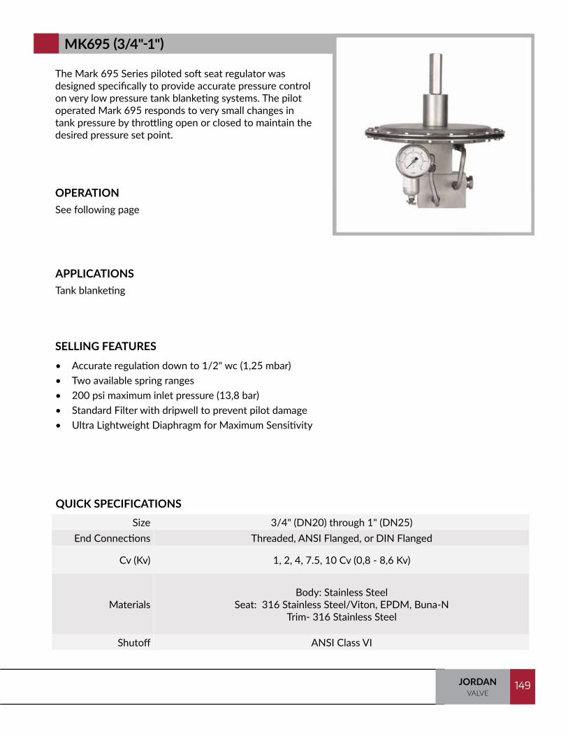
149JORDANVALVE
149
The Mark 695 Series piloted soft seat regulator was designed specifically to provide accurate pressure control on very low pressure tank blanketing systems. The pilot operated Mark 695 responds to very small changes in tank pressure by throttling open or closed to maintain the desired pressure set point.
OPERATIONSee following page
SELLING FEATURES• Accurate regulation down to 1/2" wc (1,25 mbar)• Two available spring ranges • 200 psi maximum inlet pressure (13,8 bar)• Standard Filter with dripwell to prevent pilot damage• Ultra Lightweight Diaphragm for Maximum Sensitivity
APPLICATIONSTank blanketing
QUICK SPECIFICATIONSSize 3/4" (DN20) through 1" (DN25)
End Connections Threaded, ANSI Flanged, or DIN Flanged
Cv (Kv) 1, 2, 4, 7.5, 10 Cv (0,8 - 8,6 Kv)
MaterialsBody: Stainless Steel
Seat: 316 Stainless Steel/Viton, EPDM, Buna-NTrim- 316 Stainless Steel
Shutoff ANSI Class VI
MK695 (3/4"-1")
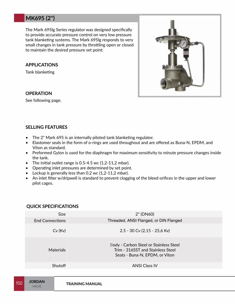
TRAINING MANUAL150 JORDANVALVE
150
The Mark 695lg Series regulator was designed specifically to provide accurate pressure control on very low pressure tank blanketing systems. The Mark 695lg responds to very small changes in tank pressure by throttling open or closed to maintain the desired pressure set point.
SELLING FEATURES
• The 2" Mark 695 is an internally piloted tank blanketing regulator. • Elastomer seals in the form of o-rings are used throughout and are offered as Buna-N, EPDM, and
Viton as standard. • Preformed Gylon is used for the diaphragm for maximum sensitivity to minute pressure changes inside
the tank. • The initial outlet range is 0.5-4.5 wc (1,2-11,2 mbar). • Operating inlet pressures are determined by set point. • Lockup is generally less than 0.2 wc (1,2-11,2 mbar). • An inlet filter w/dripwell is standard to prevent clogging of the bleed orifices in the upper and lower
pilot cages.
APPLICATIONSTank blanketing
OPERATIONSee following page.
QUICK SPECIFICATIONSSize 2" (DN60)
End Connections Threaded, ANSI Flanged, or DIN Flanged
Cv (Kv) 2.5 - 30 Cv (2,15 - 25,6 Kv)
MaterialsBody - Carbon Steel or Stainless Steel
Trim - 316SST and Stainless SteelSeats - Buna-N, EPDM, or Viton
Shutoff ANSI Class IV
MK695 (2")
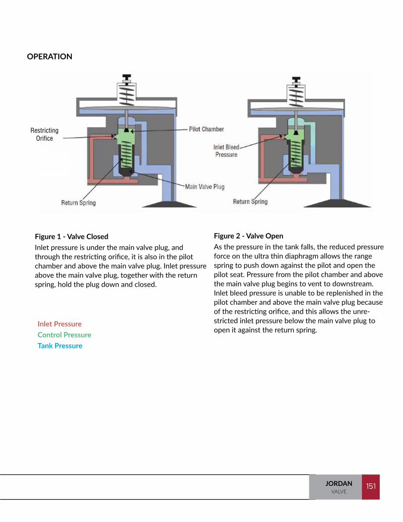
151JORDANVALVE
151
OPERATION
Inlet PressureControl PressureTank Pressure
Figure 1 - Valve Closed Inlet pressure is under the main valve plug, and through the restricting orifice, it is also in the pilot chamber and above the main valve plug. Inlet pressure above the main valve plug, together with the return spring, hold the plug down and closed.
Figure 2 - Valve Open As the pressure in the tank falls, the reduced pressure force on the ultra thin diaphragm allows the range spring to push down against the pilot and open the pilot seat. Pressure from the pilot chamber and above the main valve plug begins to vent to downstream. Inlet bleed pressure is unable to be replenished in the pilot chamber and above the main valve plug because of the restricting orifice, and this allows the unre-stricted inlet pressure below the main valve plug to open it against the return spring.
Restricting Orifice
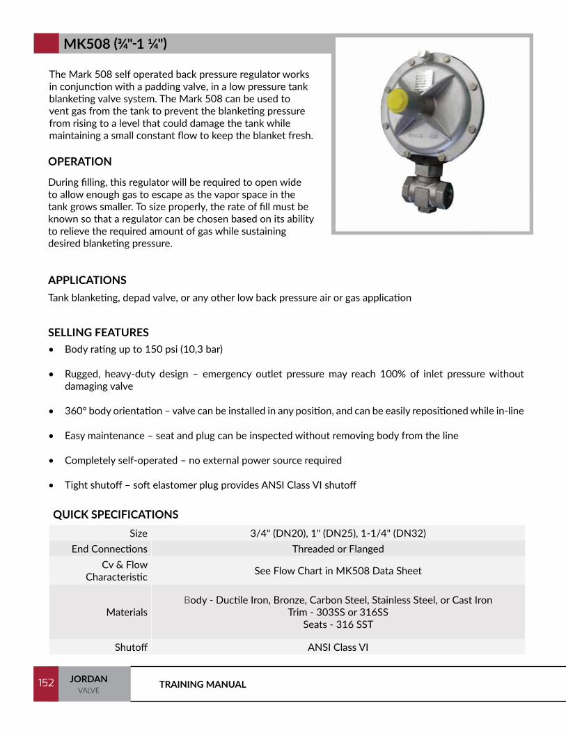
TRAINING MANUAL152 JORDANVALVE
152
The Mark 508 self operated back pressure regulator works in conjunction with a padding valve, in a low pressure tank blanketing valve system. The Mark 508 can be used to vent gas from the tank to prevent the blanketing pressure from rising to a level that could damage the tank while maintaining a small constant flow to keep the blanket fresh.
OPERATION
During filling, this regulator will be required to open wide to allow enough gas to escape as the vapor space in the tank grows smaller. To size properly, the rate of fill must be known so that a regulator can be chosen based on its ability to relieve the required amount of gas while sustaining desired blanketing pressure.
SELLING FEATURES• Body rating up to 150 psi (10,3 bar)
• Rugged, heavy-duty design – emergency outlet pressure may reach 100% of inlet pressure without damaging valve
• 360° body orientation – valve can be installed in any position, and can be easily repositioned while in-line
• Easy maintenance – seat and plug can be inspected without removing body from the line
• Completely self-operated – no external power source required
• Tight shutoff – soft elastomer plug provides ANSI Class VI shutoff
APPLICATIONSTank blanketing, depad valve, or any other low back pressure air or gas application
QUICK SPECIFICATIONSSize 3/4" (DN20), 1" (DN25), 1-1/4" (DN32)
End Connections Threaded or Flanged Cv & Flow
Characteristic See Flow Chart in MK508 Data Sheet
MaterialsBody - Ductile Iron, Bronze, Carbon Steel, Stainless Steel, or Cast Iron
Trim - 303SS or 316SSSeats - 316 SST
Shutoff ANSI Class VI
MK508 (3/4"-1 1/4")
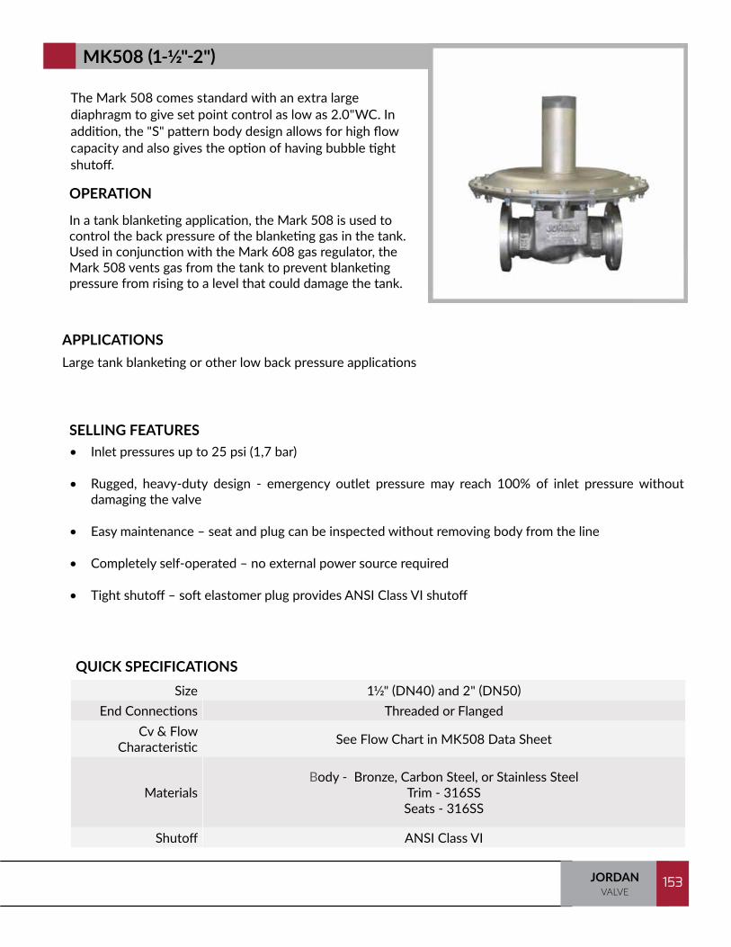
153JORDANVALVE
153
The Mark 508 comes standard with an extra large diaphragm to give set point control as low as 2.0"WC. In addition, the "S" pattern body design allows for high flow capacity and also gives the option of having bubble tight shutoff.
OPERATION
In a tank blanketing application, the Mark 508 is used to control the back pressure of the blanketing gas in the tank. Used in conjunction with the Mark 608 gas regulator, the Mark 508 vents gas from the tank to prevent blanketing pressure from rising to a level that could damage the tank.
SELLING FEATURES• Inlet pressures up to 25 psi (1,7 bar)
• Rugged, heavy-duty design - emergency outlet pressure may reach 100% of inlet pressure without damaging the valve
• Easy maintenance – seat and plug can be inspected without removing body from the line
• Completely self-operated – no external power source required
• Tight shutoff – soft elastomer plug provides ANSI Class VI shutoff
APPLICATIONSLarge tank blanketing or other low back pressure applications
QUICK SPECIFICATIONSSize 11/2" (DN40) and 2" (DN50)
End Connections Threaded or Flanged Cv & Flow
Characteristic See Flow Chart in MK508 Data Sheet
MaterialsBody - Bronze, Carbon Steel, or Stainless Steel
Trim - 316SSSeats - 316SS
Shutoff ANSI Class VI
MK508 (1-1/2"-2")
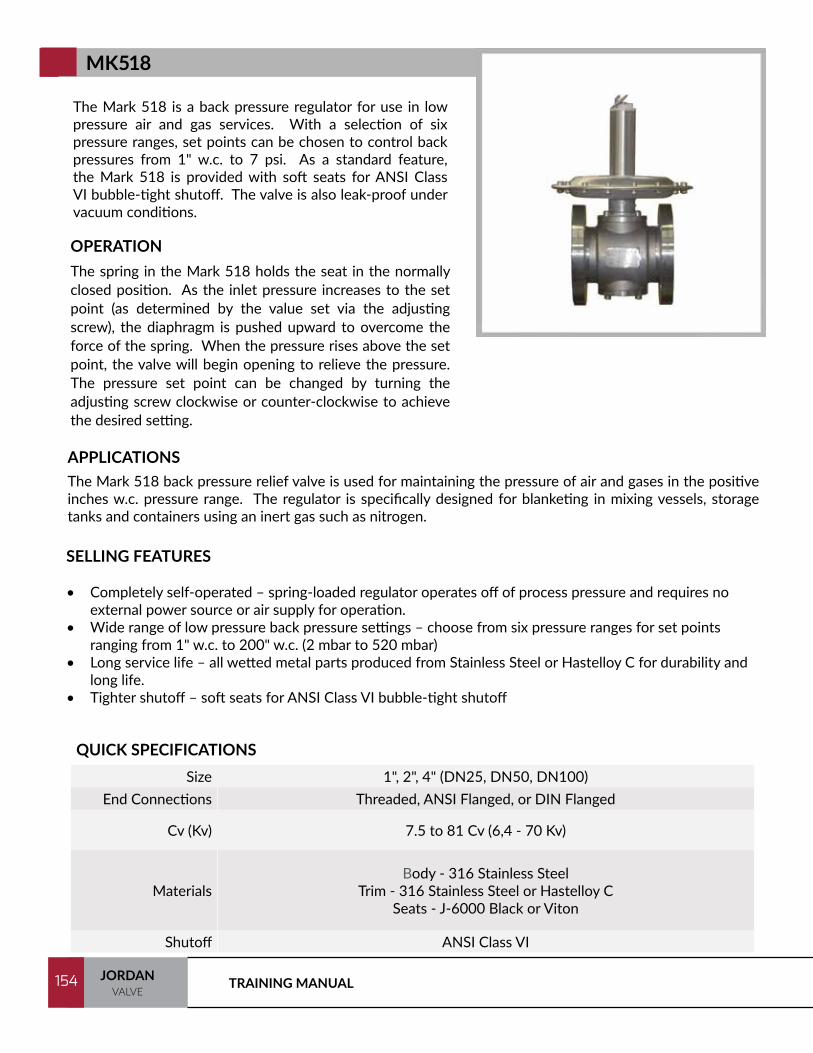
TRAINING MANUAL154 JORDANVALVE
154
The Mark 518 is a back pressure regulator for use in low pressure air and gas services. With a selection of six pressure ranges, set points can be chosen to control back pressures from 1" w.c. to 7 psi. As a standard feature, the Mark 518 is provided with soft seats for ANSI Class VI bubble-tight shutoff. The valve is also leak-proof under vacuum conditions.
OPERATIONThe spring in the Mark 518 holds the seat in the normally closed position. As the inlet pressure increases to the set point (as determined by the value set via the adjusting screw), the diaphragm is pushed upward to overcome the force of the spring. When the pressure rises above the set point, the valve will begin opening to relieve the pressure. The pressure set point can be changed by turning the adjusting screw clockwise or counter-clockwise to achieve the desired setting.
SELLING FEATURES
• Completely self-operated – spring-loaded regulator operates off of process pressure and requires no external power source or air supply for operation.
• Wide range of low pressure back pressure settings – choose from six pressure ranges for set points ranging from 1" w.c. to 200" w.c. (2 mbar to 520 mbar)
• Long service life – all wetted metal parts produced from Stainless Steel or Hastelloy C for durability and long life.
• Tighter shutoff – soft seats for ANSI Class VI bubble-tight shutoff
APPLICATIONSThe Mark 518 back pressure relief valve is used for maintaining the pressure of air and gases in the positive inches w.c. pressure range. The regulator is specifically designed for blanketing in mixing vessels, storage tanks and containers using an inert gas such as nitrogen.
QUICK SPECIFICATIONSSize 1", 2", 4" (DN25, DN50, DN100)
End Connections Threaded, ANSI Flanged, or DIN Flanged
Cv (Kv) 7.5 to 81 Cv (6,4 - 70 Kv)
MaterialsBody - 316 Stainless Steel
Trim - 316 Stainless Steel or Hastelloy CSeats - J-6000 Black or Viton
Shutoff ANSI Class VI
MK518
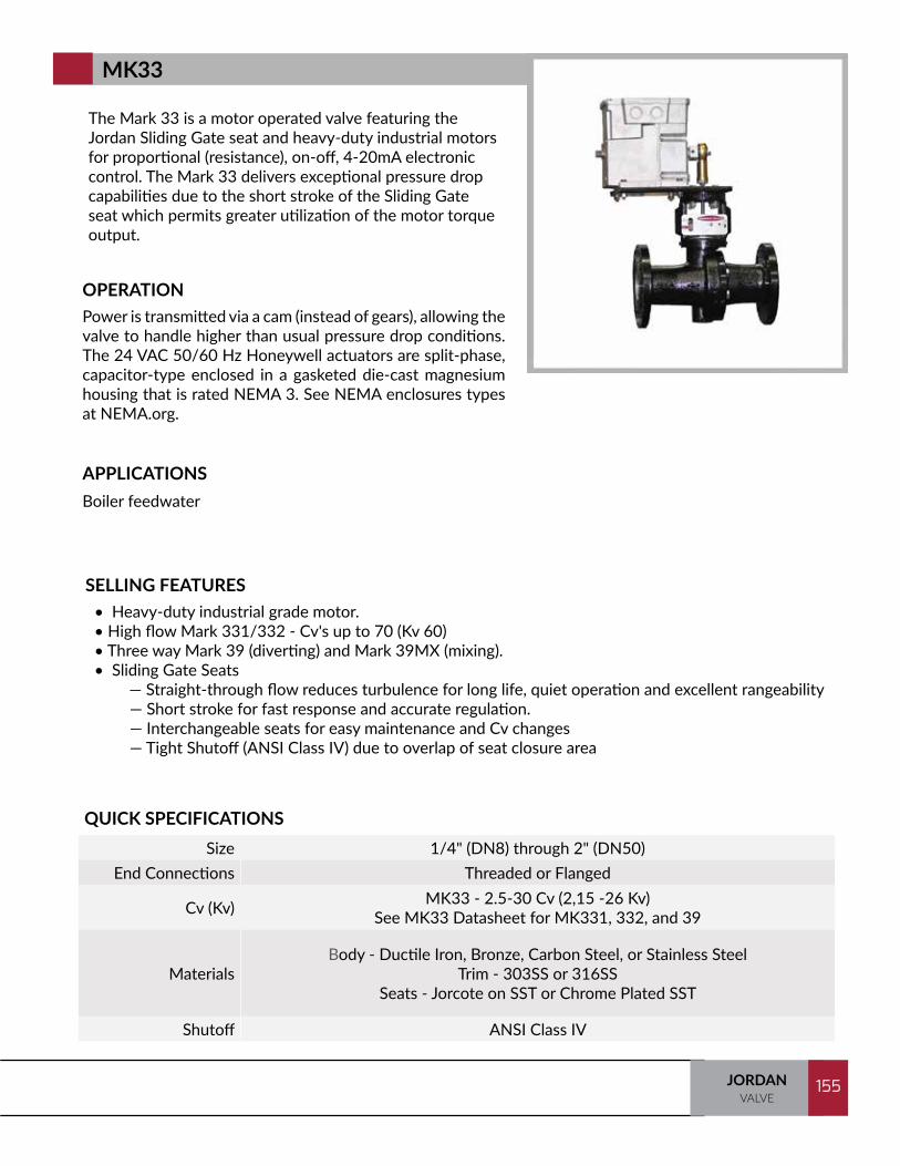
155JORDANVALVE
155
The Mark 33 is a motor operated valve featuring the Jordan Sliding Gate seat and heavy-duty industrial motors for proportional (resistance), on-off, 4-20mA electronic control. The Mark 33 delivers exceptional pressure drop capabilities due to the short stroke of the Sliding Gate seat which permits greater utilization of the motor torque output.
OPERATIONPower is transmitted via a cam (instead of gears), allowing the valve to handle higher than usual pressure drop conditions. The 24 VAC 50/60 Hz Honeywell actuators are split-phase, capacitor-type enclosed in a gasketed die-cast magnesium housing that is rated NEMA 3. See NEMA enclosures types at NEMA.org.
SELLING FEATURES• Heavy-duty industrial grade motor.• High flow Mark 331/332 - Cv's up to 70 (Kv 60)• Three way Mark 39 (diverting) and Mark 39MX (mixing).• Sliding Gate Seats — Straight-through flow reduces turbulence for long life, quiet operation and excellent rangeability
— Short stroke for fast response and accurate regulation.— Interchangeable seats for easy maintenance and Cv changes— Tight Shutoff (ANSI Class IV) due to overlap of seat closure area
APPLICATIONSBoiler feedwater
QUICK SPECIFICATIONSSize 1/4" (DN8) through 2" (DN50)
End Connections Threaded or Flanged
Cv (Kv) MK33 - 2.5-30 Cv (2,15 -26 Kv)See MK33 Datasheet for MK331, 332, and 39
MaterialsBody - Ductile Iron, Bronze, Carbon Steel, or Stainless Steel
Trim - 303SS or 316SSSeats - Jorcote on SST or Chrome Plated SST
Shutoff ANSI Class IV
MK33
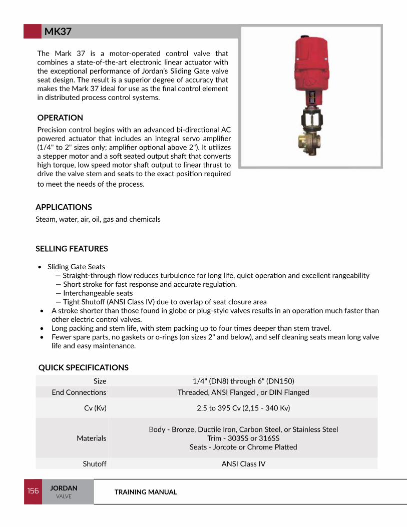
TRAINING MANUAL156 JORDANVALVE
156
The Mark 37 is a motor-operated control valve that combines a state-of-the-art electronic linear actuator with the exceptional performance of Jordan’s Sliding Gate valve seat design. The result is a superior degree of accuracy that makes the Mark 37 ideal for use as the final control element in distributed process control systems.
OPERATIONPrecision control begins with an advanced bi-directional AC powered actuator that includes an integral servo amplifier (1/4" to 2" sizes only; amplifier optional above 2"). It utilizes a stepper motor and a soft seated output shaft that converts high torque, low speed motor shaft output to linear thrust to drive the valve stem and seats to the exact position required to meet the needs of the process.
SELLING FEATURES
• Sliding Gate Seats — Straight-through flow reduces turbulence for long life, quiet operation and excellent rangeability
— Short stroke for fast response and accurate regulation.— Interchangeable seats— Tight Shutoff (ANSI Class IV) due to overlap of seat closure area
• A stroke shorter than those found in globe or plug-style valves results in an operation much faster than other electric control valves.
• Long packing and stem life, with stem packing up to four times deeper than stem travel.• Fewer spare parts, no gaskets or o-rings (on sizes 2" and below), and self cleaning seats mean long valve
life and easy maintenance.
APPLICATIONSSteam, water, air, oil, gas and chemicals
QUICK SPECIFICATIONSSize 1/4" (DN8) through 6" (DN150)
End Connections Threaded, ANSI Flanged , or DIN Flanged
Cv (Kv) 2.5 to 395 Cv (2,15 - 340 Kv)
MaterialsBody - Bronze, Ductile Iron, Carbon Steel, or Stainless Steel
Trim - 303SS or 316SS Seats - Jorcote or Chrome Platted
Shutoff ANSI Class IV
MK37

157JORDANVALVE
157
The Mark 40 and Mark 46 are designed with the unique Sliding Gate seats for level control of tanks. Both valves utilize the same design with the exception of the actuator. The Mark 40 is supplied with a float actuator; the Mark 46 is supplied with a lever with a series of drilled holes for attachment to a customer supplied actuator.
OPERATIONMark 40 - Float ActuatorMark 46 - Lever
SELLING FEATURES• Sliding Gate seats• Compact design and simple construction• High differential pressure capabilities• Extremely long packing life with short stroke• Corrosion resistant configurations with complete 316 SST materials or alloys (upon request)
APPLICATIONSSteam, water, oil, gas, air, and chemicals
QUICK SPECIFICATIONSSize 1/4" (DN8) through 6" (DN150)
End Connections Threaded or Flanged
Cv (Kv) 2.5 to 395 Cv (2,15 - 340 Kv)
MaterialsBody - Ductile Iron, Bronze, Stainless Steel, or Cast Iron
Trim - SS/BRZ, 303SS, 316SSSeats - 303SST/Jorcote and 316SS/Jorcote
Shutoff ANSI Class IV
MK40/46
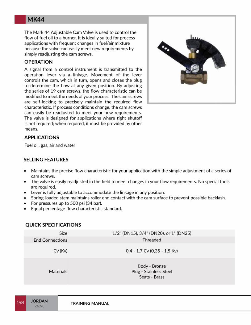
TRAINING MANUAL158 JORDANVALVE
158
The Mark 44 Adjustable Cam Valve is used to control the flow of fuel oil to a burner. It is ideally suited for process applications with frequent changes in fuel/air mixture because the valve can easily meet new requirements by simply readjusting the cam screws.
OPERATIONA signal from a control instrument is transmitted to the operation lever via a linkage. Movement of the lever controls the cam, which in turn, opens and closes the plug to determine the flow at any given position. By adjusting the series of 19 cam screws, the flow characteristic can be modified to meet the needs of your process. The cam screws are self-locking to precisely maintain the required flow characteristic. If process conditions change, the cam screws can easily be readjusted to meet your new requirements. The valve is designed for applications where tight shutoff is not required; when required, it must be provided by other means.
SELLING FEATURES
• Maintains the precise flow characteristic for your application with the simple adjustment of a series of cam screws.
• The valve is easily readjusted in the field to meet changes in your flow requirements. No special tools are required.
• Lever is fully adjustable to accommodate the linkage in any position.• Spring-loaded stem maintains roller end contact with the cam surface to prevent possible backlash.• For pressures up to 500 psi (34 bar).• Equal percentage flow characteristic standard.
APPLICATIONSFuel oil, gas, air and water
QUICK SPECIFICATIONSSize 1/2" (DN15), 3/4" (DN20), or 1" (DN25)
End Connections Threaded
Cv (Kv) 0.4 - 1.7 Cv (0,35 - 1,5 Kv)
MaterialsBody - Bronze
Plug - Stainless Steel Seats - Brass
MK44
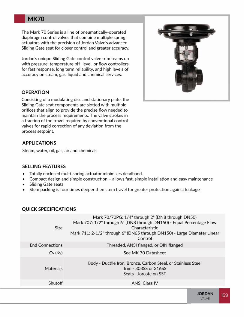
159JORDANVALVE
159
The Mark 70 Series is a line of pneumatically-operated diaphragm control valves that combine multiple spring actuators with the precision of Jordan Valve’s advanced Sliding Gate seat for closer control and greater accuracy.
Jordan’s unique Sliding Gate control valve trim teams up with pressure, temperature pH, level, or flow controllers for fast response, long term reliability, and high levels of accuracy on steam, gas, liquid and chemical services.
OPERATIONConsisting of a modulating disc and stationary plate, the Sliding Gate seat components are slotted with multiple orifices that align to provide the precise flow needed to maintain the process requirements. The valve strokes in a fraction of the travel required by conventional control valves for rapid correction of any deviation from the process setpoint.
SELLING FEATURES• Totally enclosed multi-spring actuator minimizes deadband. • Compact design and simple construction – allows fast, simple installation and easy maintenance• Sliding Gate seats• Stem packing is four times deeper then stem travel for greater protection against leakage
APPLICATIONSSteam, water, oil, gas, air and chemicals
QUICK SPECIFICATIONS
Size
Mark 70/70PG: 1/4" through 2" (DN8 through DN50)Mark 707: 1/2" through 6" (DN8 through DN150) - Equal Percentage Flow
CharacteristicMark 711: 2-1/2" through 6" (DN65 through DN150) - Large Diameter Linear
ControlEnd Connections Threaded, ANSI flanged, or DIN flanged
Cv (Kv) See MK 70 Datasheet
MaterialsBody - Ductile Iron, Bronze, Carbon Steel, or Stainless Steel
Trim - 303SS or 316SSSeats - Jorcote on SST
Shutoff ANSI Class IV
MK70

TRAINING MANUAL160 JORDANVALVE
160
The Mark 701 and Mark 702 Series provide extremely high flows in Sliding Gate, pneumatically-operated diaphragm control valves. Combined with multiple spring actuators, the Jordan Valve unique Sliding Gate control valve trim provides high levels of accuracy in a variety of services.
OPERATIONConsisting of a modulating disc and stationary plate, the Sliding Gate seat components are slotted with multiple orifices that align to provide the precise flow needed to maintain the process requirements. The valve strokes in a fraction of the travel required by conventional control valves for rapid correction of any deviation from the process setpoint.
SELLING FEATURES• Totally enclosed multi-spring actuator minimizes deadband.
• Compact design and simple construction – allows fast, simple installation and easy maintenance
• Sliding Gate seats
• Stem packing is four times deeper then stem travel for greater protection against leakage
• Available with Top or Side Mounted positioner for greater accuracy
APPLICATIONSSteam, water, oil, gas, air and chemicals
QUICK SPECIFICATIONSSize 1/2" through 2" (DN15 through DN50)
End Connections Threaded, ANSI or DIN Flanges
Cv (Kv) 6.4 – 70 Cv (5,5 – 60 Kv)
Materials
Body - Ductile Iron, Bronze, Carbon Steel, Stainless SteelTrim - 303SST or 316SSTSeats -Jorcote on SST *
* Other Materials Available
Shutoff ANSI Class IV
MK701/702

161JORDANVALVE
161
The Mark 74 Bellows Seal Control Valve provides exceptional bellows life with a valve stroke that is just a fraction of that of other rising stem valves. This means Jordan Valve can use a smaller formed bellows that has minimal movement during operation. With limited movement, the bellows is not subjected to excessive wear and fatigue – conditions that can quickly lead to failure in other designs. In actual laboratory evaluations, the valves tested exceeded two million throttling cycles in Class 300 service with no failures of the SST bellows. You can expect the Mark 74 to provide long-term, dependable service.
SELLING FEATURES• Long bellows life – in actual lab tests, the Mark 74 exceeded 2 million cycles with no bellows failures• Short stroke – a smaller bellows that has minimal movement during operation. With limited
movement, the bellows is not subjected to excessive wear and fatigue, conditions that can quickly lead to failure in other valve designs.
• Fully packed back-up seal – for additional assurance, a secondary chamber of multiple packing rings provides extra leakage protections
• Detection/monitoring port – a gauge can be mounted to verify bellows performance• Totally enclosed multi-spring actuator – minimizes deadband and is field reversible without the use of
special tools or additional parts• Specialty alloys available – ideal for toxic or corrosive services
APPLICATIONSToxic, corrosive, explosive and high temperature fluids
QUICK SPECIFICATIONSSize 1/2" (DN8) through 2" (DN50)
End Connections Threaded, ANSI Flanged, or DIN Flanged
Cv (Kv) 2.5 - 30 Cv (2,2 - 26 Kv)
MaterialsBody - Ductile Iron, Bronze, Carbon Steel, or Stainless Steel
Trim - 303SS or 316SS Seats - Jorcote on SST
Shutoff ANSI Class IV
MK74
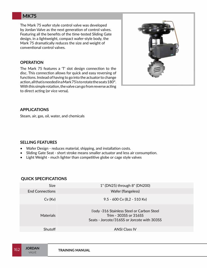
TRAINING MANUAL162 JORDANVALVE
162
The Mark 75 wafer style control valve was developed by Jordan Valve as the next generation of control valves. Featuring all the benefits of the time-tested Sliding Gate design, in a lightweight, compact wafer-style body, the Mark 75 dramatically reduces the size and weight of conventional control valves.
OPERATIONThe Mark 75 features a 'T' slot design connection to the disc. This connection allows for quick and easy reversing of functions. Instead of having to go into the actuator to change action, all that is needed in a Mark 75 is to rotate the seats 180°. With this simple rotation, the valve can go from reverse acting to direct acting (or vice versa).
SELLING FEATURES• Wafer Design - reduces material, shipping, and installation costs.• Sliding Gate Seat - short stroke means smaller actuator and less air consumption. • Light Weight - much lighter than competitive globe or cage style valves
APPLICATIONSSteam, air, gas, oil, water, and chemicals
QUICK SPECIFICATIONSSize 1" (DN25) through 8" (DN200)
End Connections Wafer (flangeless)
Cv (Kv) 9.5 - 600 Cv (8,2 - 510 Kv)
MaterialsBody -316 Stainless Steel or Carbon Steel
Trim - 303SS or 316SSSeats - Jorcote/316SS or Jorcote with 303SS
Shutoff ANSI Class IV
MK75
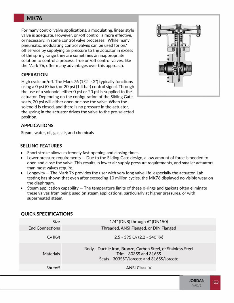
163JORDANVALVE
163
For many control valve applications, a modulating, linear style valve is adequate. However, on/off control is more effective, or necessary, in some control valve processes. While many pneumatic, modulating control valves can be used for on/off service by supplying air pressure to the actuator in excess of the spring range they are sometimes an inappropriate solution to control a process. True on/off control valves, like the Mark 76, offer many advantages over this approach.
OPERATIONHigh cycle on/off. The Mark 76 (1/2" - 2") typically functions using a 0 psi (0 bar), or 20 psi (1,4 bar) control signal. Through the use of a solenoid, either 0 psi or 20 psi is supplied to the actuator. Depending on the configuration of the Sliding Gate seats, 20 psi will either open or close the valve. When the solenoid is closed, and there is no pressure in the actuator, the spring in the actuator drives the valve to the pre-selected position.
SELLING FEATURES• Short stroke allows extremely fast opening and closing times • Lower pressure requirements — Due to the Sliding Gate design, a low amount of force is needed to
open and close the valve. This results in lower air supply pressure requirements, and smaller actuators than most valves require.
• Longevity — The Mark 76 provides the user with very long valve life, especially the actuator. Lab testing has shown that even after exceeding 10 million cycles, the MK76 displayed no visible wear on the diaphragm.
• Steam application capability — The temperature limits of these o-rings and gaskets often eliminate these valves from being used on steam applications, particularly at higher pressures, or with superheated steam.
APPLICATIONSSteam, water, oil, gas, air, and chemicals
QUICK SPECIFICATIONSSize 1/4" (DN8) through 6" (DN150)
End Connections Threaded, ANSI Flanged, or DIN Flanged
Cv (Kv) 2.5 - 395 Cv (2,2 - 340 Kv)
MaterialsBody - Ductile Iron, Bronze, Carbon Steel, or Stainless Steel
Trim - 303SS and 316SSSeats - 303SST/Jorcote and 316SS/Jorcote
Shutoff ANSI Class IV
MK76

TRAINING MANUAL164 JORDANVALVE
164
The Mark 78 pneumatic control valve is designed for accurate performance and simplified maintenance. This versatile product can be used on a variety of applications, including viscous/corrosive liquids, process gases or utility steam in process or utility service.
OPERATIONThe Mark 78 globe style control valve utilizes a cage retained seat design with unbalanced plug. The top entry cage design allows maintenance while the valve is in the line. The trim comes with stainless steel standard, or can easily accommodate special materials for maximum corrosion resistance. Threaded, welded, or flanged ends complete a truly versatile valve that covers a wide variety of applications from utility steam to process gases, to corrosive/viscous liquids.
SELLING FEATURES• Top entry cage design – allows easy, in-line maintenance• Tight shutoff - ANSI class IV (hard seats) and ANSI Class VI (soft seats)• Characterized flow options – including linear, equal percentage, quick opening, or an equal-linear
combination• High capacity – Cv's up to 60 (Kv's up to 51,6) in 2" (DN50) valves • Lift out seats – seats are not screwed in, and lift out of the valve body for easy access and quick
maintenance.
APPLICATIONSViscous/corrosive liquids, gases, or steam
QUICK SPECIFICATIONSSize 1/2" (DN15) - 2" (DN50)
End Connections Threaded , ANSI Flanges, DIN Flanges , Companion Flanges, orIntegral Flanges
Cv (Kv) 4.4 - 60 Cv (3,8 - 52 Kv)
MaterialsBody: Bronze, Carbon Steel, or Stainless Steel
Seat: TeflonTM/Stainless Steel or Metal Trim: 316SS
Shutoff ANSI Class VI with Soft SeatANSI Class IV with Hard Seat
MK78

165JORDANVALVE
165
The Mark 79 is a pneumatic 3-way control valve for use in either bypass or mixing service. The MK79 utilizes the unique Sliding Gate trim design to provide excellent control with superior longevity. Each valve contains two sets of Sliding Gate seats connected to a common valve stem for synchronized movement, whether in bypass or mixing mode.
OPERATIONThe Mark 79 is used for diverting service and is ideal for bypassing fluids around coolers or filters. In this configuration, there is one inlet and two outlets. As one outlet closes, the other outlet opens, diverting flow from one channel to the other in accordance to the air signal to the actuator.
The Mark 79MX is used as a combining or mixing valve with two inlets and one outlet. When used as a mixing valve, optimal performance will be achieved with equal pressures on both inlets. Contact factory for further information.
SELLING FEATURES• Totally enclosed multi-spring actuator minimizes deadband.• Multi-spring actuator can be configured to accept a 3-15 psi signal or other control ranges on request.• Available with a top-mounted or side mounted positioner.
APPLICATIONSSteam, oil, gas, air, water, chemicals
QUICK SPECIFICATIONSSize 1-1/2" (DN40); 2" (DN50); 3" (DN80)
End Connections Threaded or Flanged (3" Flanged Only)
Cv (Kv) 15-30 Cv (12,9 -26 Kv)
MaterialsBody -Carbon Steel or Stainless Steel
Trim - 303SS or 316SSSeats - Jorcote or Chrome Platted SST
Shutoff ANSI Class IV
MK79/MK79 MX
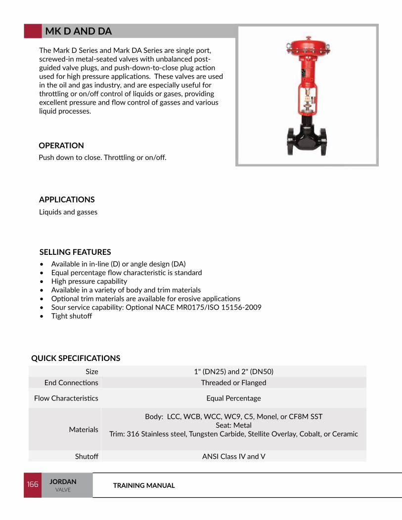
TRAINING MANUAL166 JORDANVALVE
166
The Mark D Series and Mark DA Series are single port, screwed-in metal-seated valves with unbalanced post-guided valve plugs, and push-down-to-close plug action used for high pressure applications. These valves are used in the oil and gas industry, and are especially useful for throttling or on/off control of liquids or gases, providing excellent pressure and flow control of gasses and various liquid processes.
OPERATIONPush down to close. Throttling or on/off.
SELLING FEATURES• Available in in-line (D) or angle design (DA)• Equal percentage flow characteristic is standard• High pressure capability• Available in a variety of body and trim materials• Optional trim materials are available for erosive applications• Sour service capability: Optional NACE MR0175/ISO 15156-2009• Tight shutoff
APPLICATIONSLiquids and gasses
QUICK SPECIFICATIONSSize 1" (DN25) and 2" (DN50)
End Connections Threaded or Flanged
Flow Characteristics Equal Percentage
Materials
Body: LCC, WCB, WCC, WC9, C5, Monel, or CF8M SSTSeat: Metal
Trim: 316 Stainless steel, Tungsten Carbide, Stellite Overlay, Cobalt, or Ceramic
Shutoff ANSI Class IV and V
MK D AND DA

167JORDANVALVE
167
The Mark E Series is a single port, globe-style body with composition or metal seats and a balanced push-down-to-close valve action plug.
The Mark ED Series is intended for general control applications over a wide variety of temperatures and pressure drops. This design has an upper piston ring seal and metal-to-metal seating.
The Mark ET Series is intended for applications requiring low leakage rates with composition seating (TFE) for tight shutoff requirements or metal-to-metal seating for higher temperature capabilities. The valve plug has a two-piece upper seal.
OPERATIONPush down to close.
SELLING FEATURES• Top entry cage design allows easy, in-line maintenance• Balanced Plug allows the use of smaller actuators• Characterized flow options including equal percentage, linear, and quick opening• Available in a variety of body and trim materials make the Mark E Series suitable for a variety of
applications including liquids, gasses or steam• Cage guiding allows the Mark E to handle high pressure drops while providing greater plug stability• Sour Service Capability: Optional NACE MRO175/ISO 15156-2009
APPLICATIONSNatural gas, water, steam, oil, and industrial gas
QUICK SPECIFICATIONSSize 1” (DN25) through 8” (DN200)
End Connections Raised Face or Ring Type Joint Flanges
Flow Characteristics Linear, Quick Opening, or Equal Percentage
Materials
Body: LCC, WCB, WCC, WC9, C5, Monel, or CF8M SSTSeat: Metal or PTFE
Trim: 316SST (standard), 416SST, 17-4PH, Alloy6-Co.Cr-A, Cobalt, or 316SST/Tungsten Carbide
Shutoff Mark ET: ANSI Class IV & VMark ED: ANSI Class II & III
MK ED AND ET
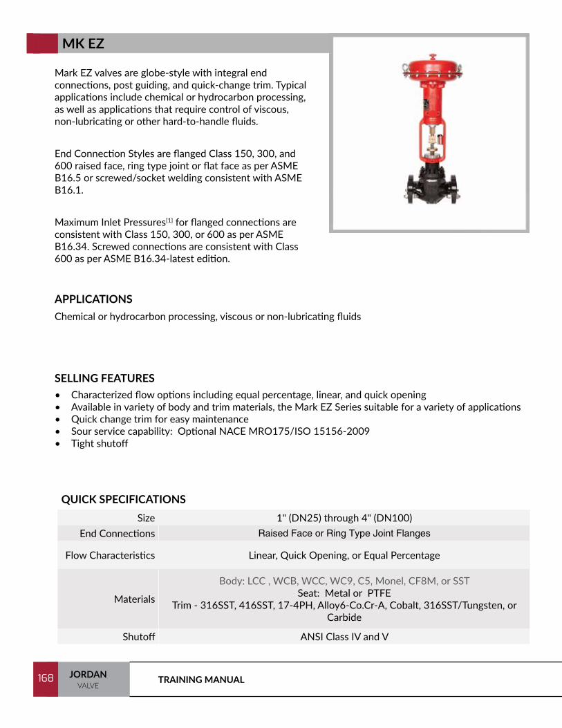
TRAINING MANUAL168 JORDANVALVE
168
Mark EZ valves are globe-style with integral end connections, post guiding, and quick-change trim. Typical applications include chemical or hydrocarbon processing, as well as applications that require control of viscous, non-lubricating or other hard-to-handle fluids.
End Connection Styles are flanged Class 150, 300, and 600 raised face, ring type joint or flat face as per ASME B16.5 or screwed/socket welding consistent with ASME B16.1.
Maximum Inlet Pressures[1] for flanged connections are consistent with Class 150, 300, or 600 as per ASME B16.34. Screwed connections are consistent with Class 600 as per ASME B16.34-latest edition.
SELLING FEATURES• Characterized flow options including equal percentage, linear, and quick opening• Available in variety of body and trim materials, the Mark EZ Series suitable for a variety of applications • Quick change trim for easy maintenance• Sour service capability: Optional NACE MRO175/ISO 15156-2009• Tight shutoff
APPLICATIONSChemical or hydrocarbon processing, viscous or non-lubricating fluids
QUICK SPECIFICATIONSSize 1" (DN25) through 4" (DN100)
End Connections Raised Face or Ring Type Joint Flanges
Flow Characteristics Linear, Quick Opening, or Equal Percentage
Materials
Body: LCC , WCB, WCC, WC9, C5, Monel, CF8M, or SST Seat: Metal or PTFE
Trim - 316SST, 416SST, 17-4PH, Alloy6-Co.Cr-A, Cobalt, 316SST/Tungsten, or Carbide
Shutoff ANSI Class IV and V
MK EZ

169JORDANVALVE
169
The Mark EW valve bodies are single port, globe-style bodies with cage guiding, clamped seat rings and push-down-to-close valve plug action. Providing excellent pressure and flow control on steam, gasses, and various liquid processes.
The Mark EWD Series is intended for general control applications over a wide variety of temperatures and pressure drops. This design has balanced valve plug with metal-to-metal seating.
The Mark EWS Series is intended for application requiring better shutoff capabilities than those suitable for the EWD. This valve uses an unbalanced valve plug with metal-to-metal seating, or optional metal-to-TFE seating.
The Mark EWT Series is suitable for applications with stringent shutoff requirements. This valve uses a balanced valve plug with metal-to-TFE seating, or metal-to-metal seating for use in higher temperatures.
SELLING FEATURES• Characterized flow options including equal percentage, linear, and quick opening• Available in a variety of body and trim materials,the Mark EW Series is suitable for a variety of
applications including liquids, gasses or steam• Anti-Cavitation trim and Noise Abatement trim available• Sour service capability: Optional NACE MRO175/ISO 15156-2009
APPLICATIONSNatural gas, water, steam, oil, and industrial gas
QUICK SPECIFICATIONSSize 8x6, 10x8, 12x6, 12x8, 16x12, 20x16, 24x16, 24x20
End Connections Raised Face, Ring Type Joint, and welded flanges
Flow Characteristics Linear, Quick Opening, or Equal Percentage
Materials
Body - LCC, WCB, WCC, WC9, C5, Monel, or CF8M SSTTrim - 316 Stainless Steel
Seats - Metal or Stainless Steel
ShutoffMK EWD: ANSI Class II, III & IVMK EWS: ANSI Class IV, V & VI
MK EWT: ANSI Class IV & V
MK EW
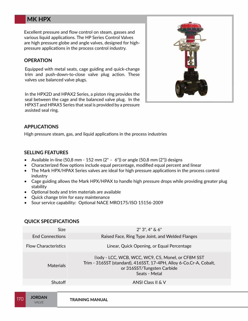
TRAINING MANUAL170 JORDANVALVE
170
Excellent pressure and flow control on steam, gasses and various liquid applications. The HP Series Control Valves are high pressure globe and angle valves, designed for high-pressure applications in the process control industry.
OPERATION
SELLING FEATURES• Available in-line (50,8 mm - 152 mm (2" – 6")) or angle (50,8 mm (2")) designs• Characterized flow options include equal percentage, modified equal percent and linear• The Mark HPX/HPAX Series valves are ideal for high pressure applications in the process control
industry• Cage guiding allows the Mark HPX/HPAX to handle high pressure drops while providing greater plug
stability• Optional body and trim materials are available• Quick change trim for easy maintenance• Sour service capability: Optional NACE MRO175/ISO 15156-2009
APPLICATIONSHigh pressure steam, gas, and liquid applications in the process industries
QUICK SPECIFICATIONSSize 2" 3", 4" & 6"
End Connections Raised Face, Ring Type Joint, and Welded Flanges
Flow Characteristics Linear, Quick Opening, or Equal Percentage
Materials
Body - LCC, WCB, WCC, WC9, C5, Monel, or CF8M SSTTrim - 316SST (standard), 416SST, 17-4PH, Alloy 6-Co.Cr-A, Cobalt,
or 316SST/Tungsten CarbideSeats - Metal
Shutoff ANSI Class II & V
Equipped with metal seats, cage guiding and quick-change trim and push-down-to-close valve plug action. These valves use balanced valve plugs.
In the HPX2D and HPAX2 Series, a piston ring provides the seal between the cage and the balanced valve plug. In the HPX5T and HPAX5 Series that seal is provided by a pressure assisted seal ring.
MK HPX

171JORDANVALVE
171
NOTES:

172
Jordan Valvea Division of Richards Industries
3170 Wasson Road Cincinnati, OH 45209 USA
513.533.5600 (T) 513.871.0105 (F)
www.jordanvalve.com
© Richards Industries – Printed in USA
JVTM/0517