train technical specification...train technical specification document no.:...
TRANSCRIPT
Train Technical
Specification Document no.: HS2-HS2-RR-SPE-000-000007
Revision Date Reason for revision
P07 26/07/2018 Version at Invitation to Tender
P11 15/03/2019 Final version for Tender updated to address Clarification Questions from Tenderers
Train Technical Specification
Document no.: HS2-HS2-RR-SPE-000-000007
Revision: P11
Page 1
Contents
Contents 1
1 Introduction 8
1.1 Document structure and content 8
1.2 Document format 9
1.2.1 Document format for ITT version of TTS 10
1.3 Collaboration in the design process 10
1.4 Tender Evaluation 11
2 Abbreviations, definitions and defined terms 11
2.1 System definitions 11
2.2 Network and route definitions 17
2.3 People 17
2.4 Layouts and payloads 18
2.5 Other defined terms and abbreviations 20
3 Strategic goals and objectives 26
4 Operational Duty 27
5 Unit and Train formation 28
6 Relevant Approvals 29
6.1 Authorisation and standards 29
6.2 Compatibility 30
6.3 Safety 30
6.4 Assurance 30
7 Performance 30
7.1 Journey times 31
7.2 Traction 31
7.3 Braking 32
7.4 EMC 34
7.4.1 Overall EMC 34
7.4.2 Mobile telephone use 35
7.5 Energy collection 35
7.5.1 Electrical power supply 35
7.5.2 Pantograph 36
7.6 Energy consumption 38
7.7 Auxiliary Power Supply 39
7.8 Structural integrity and Carbody 41
7.9 Gauging 43
7.9.1 Vehicle gauge 43
7.9.2 Compatibility with train detection systems 45
7.9.3 Electrical clearance 45
7.10 Mass and static loads 46
Train Technical Specification
Document no.: HS2-HS2-RR-SPE-000-000007
Revision: P11
Page 2
7.11 Track interaction 47
7.11.1 Track damage 47
7.11.2 Track curvature 48
7.12 Running behaviour 49
7.13 Ride quality 50
7.14 Aerodynamics 51
7.15 Access and egress 53
7.15.1 High-level goals 53
7.15.2 Moveable Step 54
7.15.3 Platform to Moveable Step interface (HS2) 55
7.15.4 Platform to Moveable Step interface (CRN) 56
7.15.5 Doorway clearway width 57
7.15.6 Dwell Time 57
7.15.7 Evacuation 57
7.15.8 Doorway positions 59
7.16 Internal climate 59
7.16.1 Saloon climate 59
7.16.2 Cab climate 64
7.16.3 Air filtration 65
7.17 Heat output 65
7.18 Acoustics 66
7.18.1 External noise 66
7.18.2 Internal noise - Saloon and Vestibule 67
7.18.3 Internal noise - Cab 69
7.18.4 General noise requirements 69
7.18.5 Communication audibility 70
7.19 Operational environment 70
7.19.1 Temperature and altitude 70
7.19.2 Precipitation and fluids 71
7.19.3 Other elements of the operational environment 72
7.20 Environmental impact 73
7.21 Fire 73
7.22 Reliability 75
7.23 Maintenance and servicing 76
7.23.1 Durations and times 76
7.23.2 Cleanability 78
7.23.3 Access for servicing tasks 79
7.23.4 Damage and vandalism 80
8 Protection and driving 82
8.1 Standards and documentation 83
8.2 General requirements 83
8.2.1 Data entry 83
8.2.2 Driver Machine Interface (DMI) 84
8.2.3 Wheel calibration 85
8.2.4 Communication requirements 85
8.2.5 Future capability 86
8.2.6 On-board CCS Performance 86
Train Technical Specification
Document no.: HS2-HS2-RR-SPE-000-000007
Revision: P11
Page 3
8.3 ETCS 87
8.3.1 ETCS functions 87
8.3.2 ETCS performance 87
8.3.3 Key management 88
8.4 AWS / TPWS 88
8.5 Protection during HS2-CRN transition 89
8.6 ATO 89
8.6.1 ATO functions 89
8.6.2 ATO Stop and Safe Location 90
8.6.3 Transitions between networks 91
8.6.4 ATO stopping accuracy 91
8.6.5 Other ATO functions 92
8.7 Manual driving (GoA1) 94
8.8 Shunting 94
8.9 Independent C-DAS 95
8.10 Voice radio 96
8.11 Other protection systems 97
9 Functionality and systems 98
9.1 Operator Settings and Software Updates 99
9.2 Diagram allocation 99
9.3 On-board controls 101
9.4 Train to Wayside and passenger communications 102
9.4.1 Non-Passenger communications 102
9.4.2 Passenger mobile communications 103
9.4.3 Passenger WiFi communications 104
9.4.4 Additional Data Communications System Provision 105
9.5 Monitoring and recording 106
9.5.1 Events 106
9.5.2 Data recording 107
9.5.3 Data recording for testing 109
9.5.4 Reset and isolation 110
9.6 Location-based functions 110
9.7 Login, states and activation times 111
9.7.1 Log-in and security 111
9.7.2 Operational states 112
9.7.3 Activation times 114
9.7.4 Train Captain settings 115
9.8 Interworking and coupling 116
9.8.1 Interworking and rescue 116
9.8.2 Coupling process 118
9.9 Traction control 122
9.10 Brake control 122
9.11 Jerk rate 124
9.12 Sanding and adhesion control 125
9.13 Power supply control 126
9.14 Energy metering 128
9.15 Pantograph control 129
Train Technical Specification
Document no.: HS2-HS2-RR-SPE-000-000007
Revision: P11
Page 4
9.16 Running Gear monitoring 130
9.17 Payload management 130
9.18 Exterior Doors 131
9.18.1 Standards 131
9.18.2 Train-wide door control 131
9.18.3 Automatic Selective Door Operation (ASDO) 134
9.18.4 Exterior Door system 136
9.18.5 Auto-close 137
9.18.6 Door obstacle detection 138
9.18.7 Door status 139
9.18.8 Emergency Egress Device 140
9.18.9 Moveable Step 141
9.19 PEP system 143
9.19.1 PEP-to-Unit Communication 143
9.19.2 Door and PEP control 144
9.20 HVAC 146
9.20.1 HVAC control 146
9.21 Heat management 148
9.22 Fire and smoke detection 149
9.22.1 Internal fire detection 149
9.22.2 External smoke control 152
9.23 Security 153
9.23.1 Physical security 153
9.23.2 Cyber security 154
9.24 Passenger Alarms and Call For Aids 154
9.24.1 Passenger Alarms 154
9.24.2 Call For Aid 155
9.25 Passenger Information System (PIS) 157
9.25.1 Visual displays 157
9.25.2 Audio information 159
9.25.3 Automatic Information Programme (AIP) 160
9.25.4 Wayfinding beacon system 163
9.25.5 Reservation and occupancy detection 163
9.26 On-board CCTV 165
9.26.1 Requirements applicable to all CCTV Systems 165
9.26.2 FFRF CCTV 168
9.26.3 Pantograph CCTV 168
9.26.4 Interior CCTV 169
9.26.5 Cab CCTV 171
9.27 Infrastructure Monitoring 172
9.27.1 Monitoring equipment to be fitted to all Units 172
9.27.2 Equipment fitted to IM Units 173
9.27.3 Unattended Geometry Measurement System (UGMS) 174
9.27.4 Unattended Overhead Measurement System (UOMS) 175
9.27.5 Signalling and Radio Frequency Monitoring System 176
9.28 Automatic vehicle identification tag 177
9.29 Maintenance and servicing 177
Train Technical Specification
Document no.: HS2-HS2-RR-SPE-000-000007
Revision: P11
Page 5
9.29.1 Train preparation 177
9.29.2 Consumable / waste monitoring 177
9.29.3 Software update 178
9.29.4 Maintenance laptop access 178
9.30 Horns 179
9.31 Exterior lights 179
9.32 Toilets and Sanitary Systems 180
9.33 Interior lighting 181
9.33.1 Lighting states and levels 181
9.33.2 Reading lights 185
9.33.3 Cab lighting control 185
9.34 Interior Doors 186
9.35 Cleaning sockets 189
9.36 Clocks / time 189
9.37 Staff communication 190
10 Interior Design and Components 190
10.1 Human factors 190
10.2 Industrial design 192
10.3 Passenger Seats 193
10.3.1 General seat design 193
10.3.2 HS2 Seats 195
10.3.3 Tip-up Seats 196
10.3.4 Premium Seats 196
10.3.5 At-seat facilities 197
10.3.6 Vestibule Seat 200
10.4 Tables 200
10.4.1 Bay tables 200
10.4.2 Seat back tables 201
10.5 Multi-Purpose Areas 201
10.6 Luggage storage 202
10.6.1 Overhead luggage racks 202
10.6.2 Luggage stacks 203
10.6.3 Bulk Luggage Storage Area 203
10.7 Wheelchair Spaces 204
10.8 Catering 205
10.8.1 Catering Trolley Stowage Point 205
10.8.2 Catering Café-Shop 205
10.8.3 Catering Kiosk 207
10.8.4 Catering flexibility 208
10.9 Train Captain and Train Crew facilities 209
10.9.1 Cab design 209
10.9.2 Cab sightlines 211
10.9.3 Train Crew facilities 212
10.10 Evacuation equipment 212
10.11 Equipment and storage 214
10.12 Gangway 216
10.13 Interior panelling and glazing 216
Train Technical Specification
Document no.: HS2-HS2-RR-SPE-000-000007
Revision: P11
Page 6
10.14 Interior partitions 217
10.14.1 Full-width Partitions 217
10.14.2 Partial Partitions 218
10.15 Interior flooring 219
10.16 Toilets 219
10.16.1 General Toilet requirements 219
10.16.2 Toilet Facilities 220
10.16.3 Toilet Controls 223
10.17 Litter collection 224
10.18 Colours and signage 225
10.19 PIS display integration 226
10.20 Interior lighting 226
10.20.1 Lighting standards 226
10.20.2 Luminaire specification and design 226
10.20.3 Illuminance levels 227
10.20.4 Reduced lighting 230
10.20.5 Emergency lighting 230
10.21 Fire extinguishers 232
11 Interior Layout 232
11.1 One-Space Layout 233
11.1.1 Passenger Seats 233
11.1.2 Wheelchair Spaces 234
11.1.3 Window size and alignment 235
11.1.4 Toilets 236
11.1.5 Luggage 237
11.1.6 Catering 238
11.1.7 PIS display position 239
11.1.8 Other equipment 239
11.2 Two-Space Layout 239
11.3 Contractually Protected Area 239
11.4 High Density Layout 239
12 Wayside Data System 242
12.1 Access and interfaces 242
12.2 WDS functions 243
12.2.1 General functions 243
12.2.2 Diagram allocation (§9.2) 244
12.2.3 Train to Wayside and passenger communications (§9.4) 244
12.2.4 Monitoring and recording (§9.5) 245
12.2.5 Location-based functions (§9.6) 247
12.2.6 Login, states and activation times (§9.7) 247
12.2.7 Traction control (§9.9) 248
12.2.8 Brake control (§9.10) 248
12.2.9 Power supply control (§9.13) 248
12.2.10 Energy metering (§9.14) 248
12.2.11 Payload management (§9.17) 249
12.2.12 Exterior Doors and PEP system (§9.18/9.19) 249
12.2.13 HVAC (§9.20) 249
Train Technical Specification
Document no.: HS2-HS2-RR-SPE-000-000007
Revision: P11
Page 7
12.2.14 Heat and smoke detection (§9.22) 250
12.2.15 Passenger Information System (§9.25) 250
12.2.16 On-board CCTV (§9.26) 252
12.2.17 Infrastructure Monitoring (§9.27) 253
12.2.18 Maintenance and servicing (§9.29) 254
12.2.19 Interior Lighting (§9.33) 254
12.2.20 Interior Doors (§9.34) 255
12.2.21 Staff communication (§9.37) 255
12.3 Timing and prioritisation 256
13 References 257

Train Technical Specification
Document no.: HS2-HS2-RR-SPE-000-000007
Revision: P11
Page 8
1 Introduction 1.0.1 This Train Technical Specification (TTS) contains the technical requirements for the
'conventional compatible' Units being procured as part of the High Speed 2 Project. The
Units will include on-board control-command and signalling (CCS) equipment, including on-
board Automatic Train Operation (ATO) as part of their scope. The scope of the TTS also
includes the Wayside Data System, which enables Train Data to be downloaded from and
uploaded to the Unit as well as being stored, interrogated and communicated to and from
other systems.
1.0.2 A single design of Unit is required that is capable of operating at the line speeds of both the
HS2 Network and existing UK Main Line Network.
1.0.3 In preparing this specification, interfaces have been defined between the Unit and:
the HS2 Network, including infrastructure, stations, energy supply systems and
wayside signalling and communications systems;
the UK Main Line Network and specifically the routes of this network over which
HS2 services will operate - the Conventional Rail Network (CRN);
other rolling stock operating on the CRN;
staff working on-board the Unit or on the wider railway;
passengers on HS2 services; and
neighbours of the HS2 Network and CRN.
1.0.4 As far as possible, the interfaces with the Unit have been specified in terms of performance
and functionality, rather than specifying the inner working of the Unit or specific design
solutions.
1.1 Document structure and content
1.1.1 This document has the following sections:
2 - Abbreviations, definitions and defined terms.
3 - Strategic goals and objectives - sets out the high-level goals for the Unit's
design.
4 - Operational duty - provides high-level information about how and where the
Unit will be operated. This section is supported by the Data Book[116], which details
information about the HS2 Network and the CRN.
5 - Unit and Train formation - defines key parameters about the length and layout
of the Unit.
6 - Relevant Approvals - sets out the top-level technical requirements from railway
Train Technical Specification
Document no.: HS2-HS2-RR-SPE-000-000007
Revision: P11
Page 9
regulations under which the Units will be introduced. The regulations define the
applicable standards and hence a significant proportion of the total requirements
for the Unit. Repetition of these requirements through the remainder of the
specification, has been avoided, except where clarifications are required.
7 - Performance - sets out the requirements for the performance of the Unit,
which influences the capacity and capability of the Unit systems and defines the
mechanical and electrical interfaces with the railway.
8 - Protection and driving - sets out requirements for control-command and
signalling systems and driving, including European Train Control System (ETCS) and
ATO.
9 - Functionality and systems - sets out requirements for how all other systems
on-board the Unit should function, and how they should integrate with wayside
systems.
10 - Interior design and components - sets out requirements for individual parts
of the interiors.
11 - Interior layout - sets out the requirements for the arrangement of interior
components in the Saloon and around the Unit.
12 - Wayside Data System - sets out requirements for the separate software /
server to enable Train Data to be downloaded from and uploaded to the Unit as
well as being stored, interrogated and communicated to and from other systems.
This is not part of the Unit, but is within the TMM's scope.
13 - References - List of standards and documents referenced by this TTS.
Individual TTS requirements defined how these references should be applied.
1.1.2 The TTS contains requirements for the design of the Unit. Requirements for processes that
shall be undertaken by the Train Manufacturer and Maintainer (TMM) in designing the Unit
to meet this TTS are defined in other schedules of the Manufacture and Supply Agreement
(MSA). Links between this document and other schedules are highlighted where
appropriate.
1.2 Document format
1.2.0.1 This TTS includes a combination of requirements and rationale to explain the source of the
requirements. Requirements are provided in the following format:
1.2.2 TTS-1261 - Requirement Name (PQTS-107)
Example requirement text.
Rationale: Explanation of the requirement
Each requirement has a unique ID (TTS-###) and name. Reference to the
equivalent requirement of the Pre-Qualification Technical Summary (PQTS)[117] is
also provided where applicable.
Train Technical Specification
Document no.: HS2-HS2-RR-SPE-000-000007
Revision: P11
Page 10
Only text contained within the box is considered part of the requirement. There
may be a number separate statements separated by a line-break which must all be
considered together as part of the requirement.
All other text is provided for guidance and information. 'Rationale' for the
requirement has been provided to explain the requirement's purpose and wider
context.
Cross-references have been included to highlight where particular requirements
relate to each other.
1.2.1 Document format for ITT version of TTS
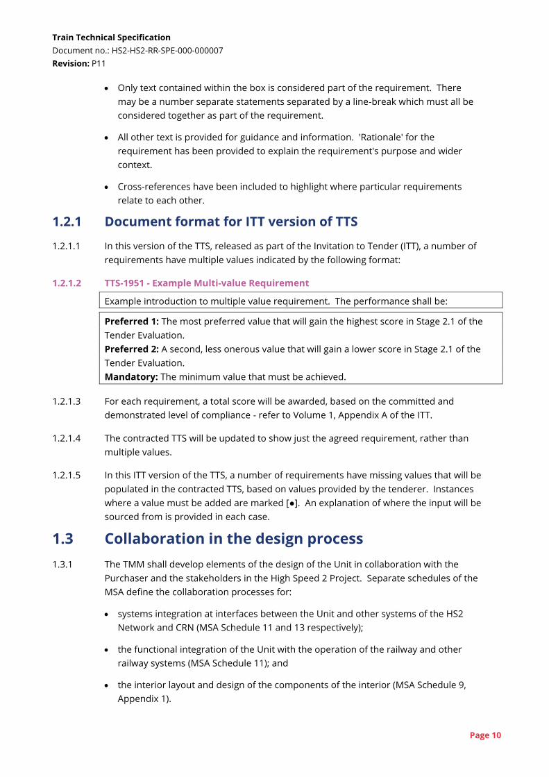
1.2.1.1 In this version of the TTS, released as part of the Invitation to Tender (ITT), a number of
requirements have multiple values indicated by the following format:
1.2.1.2 TTS-1951 - Example Multi-value Requirement
Example introduction to multiple value requirement. The performance shall be:
Preferred 1: The most preferred value that will gain the highest score in Stage 2.1 of the
Tender Evaluation.
Preferred 2: A second, less onerous value that will gain a lower score in Stage 2.1 of the
Tender Evaluation.
Mandatory: The minimum value that must be achieved.
1.2.1.3 For each requirement, a total score will be awarded, based on the committed and
demonstrated level of compliance - refer to Volume 1, Appendix A of the ITT.
1.2.1.4 The contracted TTS will be updated to show just the agreed requirement, rather than
multiple values.
1.2.1.5 In this ITT version of the TTS, a number of requirements have missing values that will be
populated in the contracted TTS, based on values provided by the tenderer. Instances
where a value must be added are marked [●]. An explanation of where the input will be
sourced from is provided in each case.
1.3 Collaboration in the design process
1.3.1 The TMM shall develop elements of the design of the Unit in collaboration with the
Purchaser and the stakeholders in the High Speed 2 Project. Separate schedules of the
MSA define the collaboration processes for:
systems integration at interfaces between the Unit and other systems of the HS2
Network and CRN (MSA Schedule 11 and 13 respectively);
the functional integration of the Unit with the operation of the railway and other
railway systems (MSA Schedule 11); and
the interior layout and design of the components of the interior (MSA Schedule 9,
Appendix 1).
Train Technical Specification
Document no.: HS2-HS2-RR-SPE-000-000007
Revision: P11
Page 11
1.3.2 This TTS sets out requirements consistent with these collaboration processes:
Section 7 sets out performance requirements related to interfaces, which support
the systems integration process;
Sections 8 and 9 set out requirements to define the range of required operational
functionality; and
Section 10 sets out requirements for interior design of the Unit. Section 11 sets out
the requirements for the interior layout.
1.3.3 To support the collaboration process a number of requirements defining provision for
future flexibility have been defined; this is indicated in titles of these requirements.
1.4 Tender Evaluation
1.4.1 Full details of the Tender Evaluation process are contained in the Invitation to Tender.
Requirements of this TTS are either:
mandatory, which is highlighted in the title of each requirement;
scored; or
contribute to the whole life value model.
2 Abbreviations, definitions and defined terms
2.1 System definitions
2.1.1 The top-level systems that are defined in this TTS are consistent with the Technical
Specifications for Interoperability (TSIs) and subsystems defined in the Interoperability
Directive[1].
Unit - A formation of vehicles, which can operate by itself or coupled to another Unit. A
Unit comprises both On-board CCS and Rolling Stock subsystems and requirements
referring to 'Unit' apply to both subsystems.
IM Unit - A Unit which has been fitted with infrastructure monitoring equipment.
Train - An operational formation of one or more Units, with all coupled Units controlled
from a single Cab. Each Unit may be orientated in either direction.
200m Train is a Train formed of one Unit
400m Train is a Train formed of two coupled Units
Vehicle - a carriage or locomotive within the Unit, as defined in the LOC&PAS TSI[4].
Train Technical Specification
Document no.: HS2-HS2-RR-SPE-000-000007
Revision: P11
Page 12
On-board CCS - all parts of the Unit that form part of the 'on-board control-command and
signalling subsystem' as defined in paragraph 2.4 of Annex II of the Interoperability
Directive[1]. The On-board CCS is considered to be composed of the following sub-systems:
ETCS On-board;
AWS/TPWS On-board - the national train control system;
ATO On-board - this is an ATO over ETCS solution, referred to as "ATO-OB" in [19];
GSM-R/GPRS Voice Radio On-board;
Interoperable C-DAS - a Connected Driver Advisory System as defined in AoE
SRS[19], section 7.12; and
Independent C-DAS Onboard - a Connected Driver Advisory System where ERTMS
is not available.
Rolling Stock - all parts of the Unit that form part of the 'rolling stock subsystem' as
defined in paragraph 2.7 of Annex II of the Interoperability Directive[1]. The following
systems, components and areas of the Rolling Stock, and the scope of each item, are
defined to ensure clarity of requirements. The systems and components are not required
to be procured to align with these scope definitions.
Auxiliary Power Supply – all elements of the Unit that supply power to systems
other than traction. This includes (if used) auxiliary convertors, main batteries, local
batteries, battery chargers, capacitors and cabling from the transformer through to
the systems. The definition of 'Auxiliary Power Supply' includes the air supply if this
is used to power auxiliary systems such as doors.
Bulk Luggage Storage Area - area for large luggage as defined in Section 10.6.3.
Cab - the area of the Unit from where the Train Captain controls the Train.
Cab CCTV System - a CCTV system recording images of the interior of the Cab - see
Section 9.26.5.
Cab Door – a door on the side of the Unit that leads from outside the vehicle to the
cab only. Note that the Unit is not required to have dedicated Cab Doors.
Cab HVAC – the HVAC for the Cab.
Call For Aid – a device for summoning help.
Carbody – the assembled structural shell of the Vehicle, excluding Windows and
Exterior Doors.
Catering Area – the area of the Vehicle immediately surrounding the catering
facilities. Catering facilities include the Catering Trolley Stowage Point, the Catering
Café-Shop and the Catering Kiosk.
CCTV System – a Unit-based closed-circuit television system - see Section 9.26.
Train Technical Specification
Document no.: HS2-HS2-RR-SPE-000-000007
Revision: P11
Page 13
Crew Control Point – a touch screen, handset and other controls (if necessary)
that enables Train Crew to access the train management system to give Train Crew
a subset of controls and information for on-board systems.
CRN Pantograph – a pantograph to be used on the CRN. This may be the same
component as the HS2 Pantograph, provided it is compatible with both networks.
Digital On-board Repeater (D-OBR) - A system for boosting public mobile
networks for Passengers on-board the Unit.
Energy Metering System - equipment and software to monitor the energy usage
of the Unit. This may be incorporated into traction / line voltage systems.
Evacuation Doors – Exterior Doors that form part of the primary evacuation route
for controlled evacuation of all people on the Unit.
Exterior Door – a door to the side of the Unit that leads to a Vestibule, from where
a Saloon or a Cab can be accessed. It is recognised that the Moveable Step may be
part of the same procured system, but the Exterior Door and Moveable Step are
treated as separate systems for the purposes of requirements.
Evacuation Device – a ramp / stepped device carried on the Unit that facilitates
evacuation of people from the Unit to locations other than a platform.
Evacuation Wheelchair – a device carried on the Unit, into which a wheelchair
user can transfer in order to facilitate evacuation from the Unit - defined by TTS-
330.
Exterior Doorway – the area of the Vehicle around the Exterior Door including the
aperture in the carbody, any trim and flooring.
Forward Facing/Rear Facing (FFRF) CCTV System – a CCTV system showing
images looking forward/rear from the Cab – see Section 9.26.2.
Full Seat Bay: an arrangement of four Passenger Seats around a table.
Full-width Partition – a partition that fully divides a Vehicle, which includes an
Interior Door.
Gangway – a flexible connection that allows safe movement of people between
Vehicles.
Half Seat Bay – an arrangement of two Passenger Seats opposite each other
around a table.
Heating, Ventilation and Air Conditioning (HVAC) – all of the systems and
controls that provide heating, cooling and ventilation (including fresh air provision
and exhaust of stale air).
HDL Seat – a Passenger Seat used in the HDL as defined in Section 11.4.
HS2 Pantograph – a pantograph to be used on the HS2 Network. This may be the
Train Technical Specification
Document no.: HS2-HS2-RR-SPE-000-000007
Revision: P11
Page 14
same component as the CRN Pantograph, provided it is compatible with both
networks.
HS2 Seat – a Passenger Seat meeting the requirements of Sections 10.3.1 and
10.3.2 of this TTS.
Interior CCTV System – a CCTV system recording images of the Saloon, Vestibules
and other interior areas – see Section 9.26.4.
Interior Door – a powered door that separates areas of the Vehicle, including
between the Saloon, the Vestibule and the gangway. A Full-width Partition will
include an Interior Door. The scope of the Interior Door includes any controls,
sensors and drives. Doors for toilets are not part of the Interior Door scope.
Litter Bin – a bin for the collection of waste from Passengers, compliant with
Section 10.17.
Moveable Step – a retractable device integrated into the Vehicle forming a step
with the door threshold, fully automatic and activated/controlled in conjunction
with the door release and closing sequences to reduce the gap in width and height
between Vehicle and platform - as defined by EN 14752[40] with additional reference
to door release.
Multi-Purpose Area – a seating bay which can be converted into an open area for
luggage or buggies - see Section 10.5.
On-board Ramp – a manual device that is positioned between the vehicle door
threshold and the platform.
Pantograph CCTV System – a CCTV system showing images of the pantograph and
pantograph well – see Section 9.26.3.
Partial Partition – a partition that visually breaks-up the Vehicle into separate
spaces but does not block the aisle clearway in any way.
Passenger Alarm – a device for alerting the Train Captain in an emergency.
Passenger HVAC – the HVAC for the Saloon, Vestibule, Toilets and Catering Areas.
Passenger Information System (PIS) – all of the components that provide general
audio and visual information to Passengers, including public address functionality.
Passenger Seat – an individual seat for one passenger, including the mounting of
that seat to the Vehicle and any facilities provided at that seat.
Premium Seat – a Passenger Seat meeting the requirements of sections 10.3.1 and
10.3.4 of this TTS.
Public WiFi Network - A system that provides WiFi to Passengers on-board the
Unit and communicates with the Wayside.
Running Gear – the wheels and suspension that provide support and guidance for
Train Technical Specification
Document no.: HS2-HS2-RR-SPE-000-000007
Revision: P11
Page 15
the Vehicle.
Saloon – the area of the Unit where passengers will normally sit, bounded by Full-
width Partitions at each end.
Saloon Section – a portion of a Saloon, measured between Partitions, for which
separate lighting settings can be applied, as defined by TTS-1089.
Sanitary Systems – the toilet bowl, flush, effluent system, fresh water supply and
sink facilities. It is assumed that to meet the requirements of this TTS a ‘bio-reactor’
effluent system will be required.
Seating Position – an individual Passenger Seat or Wheelchair Space and the space
associated with that seat or space. (Note that Vestibule Seats are not considered
Seating Positions).
Seat-back Table - a table mounted to the back of a seat in front or to another
feature if the seat faces a partition or other feature.
Signalling and Radio Frequency Monitoring System – a system on IM Units
measuring signal strength of CCS systems, as defined in section 10.4.2.
Standard Toilet – a smaller Toilet, as defined by PRM TSI[6] sections 5.3.2.2 and
5.3.2.3 and section 10.16 of this TTS.
Tip-up Seat – a sub-type of HS2 Seat meeting the requirements of Sections 10.3.1,
10.3.2 and 10.3.3.
Toilet – the whole module containing the passenger facing elements of the
Sanitary Systems and other facilities. This includes the door for the Toilet and any
controls, locks and drives for this door.
Unattended Geometry Measurement System (UGMS) – a system on IM Units
measuring track geometry.
Unattended Overhead Measurement System (UOMS) – a system on IM Units
measuring OCS/OLE.
Universal Toilet – a large Toilet, in particular providing facilities for wheelchair
users, as defined by PRM TSI[6] sections 5.3.2.2 and 5.3.2.4 and Section 10.16 of this
TTS.
Vestibule – the area of the Unit immediately inside the Exterior Doors. Where
separate requirements apply to the Saloon and Vestibule, the Interior Doors
between the two will define the boundary.
Vestibule Seat – a fold-down seat fitted in a Vestibule.
Wheelchair Space – a position where a passenger using a wheelchair can locate
their wheelchair as defined by PRM TSI Section 4.2.2.2.
Window – The main bodyside windows for Passengers to view the outside of the
Train Technical Specification
Document no.: HS2-HS2-RR-SPE-000-000007
Revision: P11
Page 16
Unit from the Saloon. This does not include windscreen, cab side windows,
windows in Exterior Doors or internal glazing.
Wayside – a generic name for systems outside the Unit which the Unit will communicate
with. This will include the Network Integrated Control Centre (NICC). The majority of the
Wayside will be outside the TMM's scope, but the TMM will need to provide equipment to
interpret and store Train Data that is transmitted to and from the Unit - the Wayside Data
System.
Wayside Data System (WDS) - software and data storage that enables Train Data to be
downloaded from and uploaded to the Unit as well as being stored, interrogated and
communicated to and from other systems.
3rd Party Applications - software and hardware that can connect with the Wayside Data
System to send and receive data and provide commands.
The Wayside includes the CCS Trackside which is outside the scope of supply of the TMM.
It comprises:
ATO Trackside - the trackside component of the ATO; and
ETCS Trackside - the trackside component of ETCS.
Special Operator Equipment - equipment that is designed, built and supplied by the TMM
for use in operating the Units, which includes:
rescue couplers - as required by TTS-375 - see Section 9.8.1.3 for definition and
Schedule 14 for quantity;
On-board Ramps - as required by TTS-268 - one ramp per Vehicle with Wheelchair
Spaces;
Evacuation Devices - as required by TTS-2802 - two per Unit;
Evacuation Wheelchairs - as required by TTS-2802 - four per Unit;
door barriers - as required by TTS-3337 - one per Vestibule;
access keys for Train Captains, Train Crew and cleaners - as required, in part, by
section 9.23 and TTS-740 - see Schedule 14 for quantity;
contactless log-in cards (or similar) - as required by TTS-605 - see Schedule 14 for
quantity;
removable CCTV storage media - as required by TTS-558 - see Schedule 14 for
quantity; and
track circuit clips, flags and ladders - as required by TTS-3444 - see requirement for
quantities.
Train Technical Specification
Document no.: HS2-HS2-RR-SPE-000-000007
Revision: P11
Page 17
2.2 Network and route definitions
Conventional Rail Network (CRN) – the parts of the UK Main Line Network over which
HS2 services will operate, as defined in MSA Schedule 4. Note that the CRN is not a subset
of the HS2 Network.
East Coast Mainline (ECML) – the conventional main line between London, Leeds, York,
Newcastle and Edinburgh - see Data Book[116] for the list of CRN routes which form part of
the ECML.
High Speed Two (HS2) Network – the new infrastructure and railway systems being
constructed as part of the High Speed 2 Project over which HS2 services will operate. This
is defined in Schedule 4 of the MSA. Note that the CRN is not a subset of the HS2 Network.
West Coast Mainline (WCML) – the conventional main line between London, Birmingham,
Liverpool, Manchester and Scotland - see Data Book[116] for the list of CRN routes which
form part of the WCML.
UK Main Line Network – The UK-wide main line rail network maintained and operated by
Network Rail. The CRN is a subset of the UK Main Line Network.
More detailed definition of all routes is provided in MSA Schedule 4.
2.3 People
2.3.1 The following people are defined within this TTS. Where necessary, the range of sizes
defined in TTS-291 shall be considered for each of these people.
Authorised Person - the Train Captain, any member of Train Crew, and any member of
station staff who is authorised to carry out actions related to the Unit, or any person who is
permitted to access the Unit when it is not in passenger service.
Catering Staff - an employee of the HS2 Train Operator, or their catering sub-contractor,
who is responsible for staffing catering facilities and equipment.
Instructor - a person who instructs and trains trainee Train Captains.
Maintenance Technician - a person who undertakes maintenance tasks on the Unit.
These include changes to the Unit the Train Captain or Train Crew are not permitted to
make.
Passenger - a passenger of HS2 services who travels on an HS2 service.
Restricted Persons - a sub-group of Authorised Persons who are able to access particular
security-related areas or devices.
Train Captain - The person with overall control of the Train, who will drive the Train on the
CRN; and drive or provide supervision from the cab on the HS2 Network. The Train Captain
will control the whole Train, including all coupled Units.
Train Technical Specification
Document no.: HS2-HS2-RR-SPE-000-000007
Revision: P11
Page 18
Train Crew - Authorised Persons on the Train while it is in service between stations, who
are employed by the HS2 Train Operator, excluding the Train Captain and Instructor (if
present).
User Population - any person using the Unit from within the range defined in TTS-291.
This term is used for requirements relating to ergonomics and anthropometrics.
Wayside Staff - a person on remote from the Unit with access to the Wayside Data System.
This person may work for the TMM, the HS2 Infrastructure Manager, the HS2 Train
Operator or another party.
2.4 Layouts and payloads
2.4.1 The Unit is required to have flexibility for future internal reconfiguration during the design
phase or later in the Unit's life. To achieve this, a number of layouts are defined within this
TTS:
One-Space Layout (1SL) which provides a single seating space throughout the
whole Unit; the service offering would be varied by features other than seat
arrangement. This layout is defined by the requirements in Section 11.1.
Two-Space Layout (2SL) which is a variant on the 1SL that incorporates a different
seat design in some Vehicles. This layout is defined by a set of changes to the 1SL
requirements, which are listed in Appendix R. It is used in a number of the Stage 5
Whole Life Value requirements.
High Density Layout (HDL) which is the maximum seating and standing capacity
that the Unit can provide. This layout is used to define the envelope of future
flexibility. This layout is defined by the requirements in Section 11.4.
2.4.2 It is anticipated that either the 1SL or 2SL will be selected prior to contract award as the
base layout. The requirements for this base layout, and the layout itself, may be varied
through the project according to the interiors collaboration process described in MSA
Schedule 9, Appendix 1. The HDL will not be changed through the collaboration process as
it represents the maximum envelope for the collaboration process and any future
reconfiguration.
2.4.3 A number of payloads are defined for these layouts. These payloads are referenced
throughout the TTS and the use of these payloads is summarised in Appendix B.
2.4.4 The following four definitions define the maximum payload conditions for the Unit, based
on the HDL. The TTS contains requirements for safe operation of the Unit (such as braking,
dynamics and axle loads) based on these payloads to ensure the Unit can safely be
operated up to these limits in the future.
2.4.5 The definitions have the following clarifications to EN 15663[46]:
Rationale: The terminology of the TTS is based on the 2009 version of EN 15663[46]. Use of the 2017
version would require significant re-drafting of the TTS for consistency and so has not been adopted.
Train Technical Specification
Document no.: HS2-HS2-RR-SPE-000-000007
Revision: P11
Page 19
Passenger mass per seat shall be 90kg including 10kg luggage;
Passenger mass for standing areas shall be 80kg (i.e. no luggage); and
Tip-up Seats and folding tables in Multi-Purpose Areas shall be considered to be in
the 'down' / deployed position so that they act as seats with no standing area.
Rationale: Data for the UK shows that the average mass is currently 76kg per person. 90kg has been
specified to give 10kg provision of luggage per person and scope for average mass to grow. No
luggage provision is made for standing Passengers, since luggage would weigh less than further
Passengers that could stand where the luggage would be. The Multi-Purpose Area is intended to be
reconfigured in the off-peak to provide additional storage (e.g. for buggies); it is not intended as a
standing area.
Normal Operational Payload (HDL) - operational mass under normal payload as defined
in EN 15663[46] for high speed and long distance vehicles except that passenger mass shall
be 90kg including luggage and Tip-up Seats shall be in the down position. This shall be
calculated using the HDL defined in Section 11.4.
Normal Payload (HDL) - design mass under normal payload as defined in EN 15663[46] for
high speed and long distance vehicles except that passenger mass shall be 90kg including
luggage and Tip-up Seats shall be in the down position. This shall be calculated using the
HDL defined in Section 11.4.
Exceptional Payload (HDL) - design mass under exceptional payload as defined in EN
15663[46] for high speed and long distance vehicles with 90kg per person for all seated
passengers and [●] kg/m² in standing and catering areas and Tip-up Seats in the down
position. This shall be calculated using the HDL defined in Section 11.4.
Update for contract - standing density to be updated based on the response to Section 11.4
Exceptional Payload (HDL+RA) - design mass under exceptional payload as defined in EN
15663[46] for high speed and long distance vehicles with 80kg per person for all seated
passengers and 320kg/m² in standing and catering areas and Tip-up Seats in the down
position. This shall be calculated using the HDL defined in Section 11.4. This payload is
only used for requirement TTS-133.
Rationale: This alternative value for Exceptional Payload is used solely for specification of Route
Availability (RA) number in accordance with GE/RT8006[100]. Network Rail has confirmed that this
separate payload condition should be used for consistency with existing analysis of underline
bridges.
2.4.6 The two definitions below define the payload conditions to be used for key performance
requirements such as journey time, dwell time and energy consumption. A combination of
the 1SL and 2SL will be used for these purposes. During the course of the contract, if
changes are made to the layout from the base layout through the collaboration process,
these payloads will change, and the impact on performance requirements will need to be
assessed as part of agreeing the final scope of change. It is anticipated that these final
payloads will be used for compliance with Mandatory Standards to support Relevant
Approvals.

Train Technical Specification
Document no.: HS2-HS2-RR-SPE-000-000007
Revision: P11
Page 20
Normal Payload (1SL) - design mass under normal payload as defined in EN 15663[46] for
high speed and long distance vehicles except that passenger mass shall be 90kg including
luggage and Tip-up Seats shall be in the down position. This shall be calculated using the
1SL defined in Section 11.1.
Normal Payload (2SL) - design mass under normal payload as defined in EN 15663[46] for
high speed and long distance vehicles except that passenger mass shall be 90kg including
luggage and Tip-up Seats shall be in the down position. This shall be calculated using the
2SL, which is defined in Section 11.1 modified by Appendix R.
2.4.7 For the purposes of Relevant Approvals, Exceptional Payload in the 1SL / 2SL condition is
defined as follows.
Exceptional Payload (1SL) - design mass under exceptional payload as defined in EN
15663[46] for high speed and long distance vehicles with 90kg per person for all seated
passengers and up to 320kg/m² in standing and Catering Areas and Tip-up Seats in the
down position. This shall be calculated using the 1SL defined in Section 11.1. If the 2SL is
later chosen as the base layout, payloads will be based on the 2SL instead. The mass of
standing passengers shall be varied to a single value for the whole Unit up to 320kg/m², but
such that the payload of any vehicle is no higher than Exceptional Payload (HDL) of that
vehicle.
2.4.8 The following payload is defined as the lightest possible payload. The 2SL is specified since
this is considered to achieve the least amount of equipment inside a Vehicle. If the 1SL is
chosen as the base layout, these requirements will be updated to refer to the 1SL prior to
contract award.
Working Order (2SL) - design mass in working order payload as defined in EN 15663[46] for
high speed and long distance vehicles. This shall be calculated using the equipment of the
2SL defined in Section 11.2. If the 1SL is later chosen as the base layout, payloads will be
based on the 1SL instead.
2.4.9 Appendix B has a summary of requirements that refer to a payload and which payload is
applicable in each case. It also includes an explanation of how it is anticipated that the
payload and HDL will be defined.
2.5 Other defined terms and abbreviations
3-pin Socket - is a 230V AC, 3-pin socket that complies with BS 1363-2[23] - i.e. the normal
UK socket.
Abnormal PTI Conditions - vehicle conditions that affect the Platform-Train Interface that
are unusual and rarely-experienced and not part of the normal maintenance cycle,
including:
Payload above the Normal Payload (HDL) limit
[●]
Train Technical Specification
Document no.: HS2-HS2-RR-SPE-000-000007
Revision: P11
Page 21
Update for contract - further Vehicle conditions to be added based on the response to
requirement TTS-154, section 7.11.1 in the TTS Response Spreadsheet.
Active Cab - the Cab of the Train that is currently being used by the Train Captain to
control the Train.
ASDO - Automatic Selective Door Operation - a system / function for automatically
restricting which Exterior Doors can open at a particular platform.
ATO - Automatic Train Operation, operated over ETCS.
ATO Stop - is a control in the Cab for unplanned, controlled stopping of the Train.
ATO Traction / Brake Control - is the feature of the driving function of ATO On-board as
described in ATO over ETCS SRS[19] Section 7.1.5.
Automatic Dropping Device (ADD) - device that lowers the pantograph in the event of
pantograph head failure or damage of the pantograph head.
Automatic Information Programme (AIP) - is an automated set of visual and audible
messages broadcast during a Service - see Section 9.25.3.
Automatic Train Stopping Management - is the feature of the driving function ATO On-
board as described in ATO over ETCS SRS[19] Section 7.1.4.
AWS - Automatic Warning System - UK national train protection system - refer to RIS-0775-
CCS[79].
Bicycle - a bicycle with 740mm wheels, a 580mm frame (i.e. seat tube measurement),
1050mm wheelbase and 460mm width handlebars.
CCS - Control-command and Signalling.
Connected Driver Advisory System (C-DAS) - a Driver Advisory System that includes two-
way communication between the Train and the Wayside to enable the provision of
schedule, routing and speed restriction updates to the Train in near real time, and also
receipt of information from the Train to improve train regulation decisions. On the HS2
Network, C-DAS will operate over ETCS.
Contractually Protected Area - a minimum internal area which must be available for
flexible reconfiguration of the interior, as defined in Section 11.
CRN Contact Quality Criteria - the criteria for assessing compatibility between a
pantograph and the CRN OLE, defined by GM/RT2111[84] Clause 4.9.1.3.
Data Book - sets of data that support this TTS, providing details about the HS2 Network
and CRN - reference [116].
Design - the design of the Units and Equipment that is developed through the Design
Phase and defined by the Design Documentation.
Train Technical Specification
Document no.: HS2-HS2-RR-SPE-000-000007
Revision: P11
Page 22
Discharge Water - Waste water produced by the Sanitary System that complies with
LOC&PAS TSI[4] Clause 4.2.5.1 (2).
Driver Machine Interface (DMI) - this is specifically the DMI for On-board CCS and not
other train control screens that may be provided.
Dwell Time - the time taken for a Unit to perform all normal aspects of station operations
from wheels-stop to wheels-start including alighting and boarding of passengers.
EIRENE SRS - European Integrated Railway Radio Enhanced Network System Requirements
Specification.
EMC - Electromagnetic compatibility.
Emergency Egress Device - a device for opening an Exterior Door in an emergency. This is
referred to as an 'emergency-opening device' in the LOC&PAS TSI[4].
ETCS - European Train Control System.
ERTMS - European Rail Traffic Management System.
Eurobalise - a wayside transmission unit, used in an ERTMS/ETCS installation, that uses the
magnetic transponder technology. Its main function is to transmit information through the
air gap. The Eurobalise is a single device mounted on the track, which communicates with a
Unit passing over it.
EUAR - European Union Agency for Railways - Replaces the European Rail Agency (ERA).
Event - an occurrence on the Train that the Train records together with appropriate data
and warnings - as defined in Section 9.5.1.
EVC - European Vital Computer.
Fit for Service - has the meaning given in Appendix 3 (Meaning of Fit for Service) to
Schedule 5 (Performance Regime) of the TSA.
FHD - Full High Definition.
Fleet - all of the Units supplied as part of this Agreement (the MSA) and any further Units of
the same design that are later supplied.
FMECA - Failure Mode, Effects and Criticality Analysis.
FRMCS - Future Railway Mobile Communication System.
Full Shut-down State - an operational state where the Unit is not connected to the 25kV
power supply; all systems are switched off so no power is consumed - see section 9.7.2.
Grade of Automation level 2 (GoA2) - GoA2 is semi-automatic train operation where
starting and stopping is automated, but a Train Captain remains in the cab and can drive
the Train if needed and handle emergencies.
Train Technical Specification
Document no.: HS2-HS2-RR-SPE-000-000007
Revision: P11
Page 23
GNSS - Global Navigation Satellite System.
GPRS - General Packet Radio System.
GSM-R - Global System for Mobile Communications – Railway.
HS2 Platform - a platform nominally positioned at 1115mm above rail and an offset
consistent with GC gauge (as defined in EN 15273-3[45]). For the purpose of Step-free
Access requirements, any tolerance in platform height may be ignored (i.e. the impact of
tolerance between the track and platform will be managed by HS2).
HS2 Train Operator - any entity nominated by the Secretary of State and/or the Purchaser
to operate the HS2 Services.
Inactive Cab - any cab in the Train other than the Active Cab.
Infrastructure Train Data - any Train Data to the extent that such data relates to the CRN,
HS2 Network or other Railway Infrastructure on which any of the Units operate from time
to time, including associated Unit metadata.
ITT - Invitation to Tender.
Key Management Centre - as defined in SUBSET-026[16] Chapter 2, section 2.5.
Large Bag - a bag with dimensions of 800 × 570 × 300mm.
Limited Heat Release State - is an operational State where systems are configured to
minimise heat output from the Unit while providing the best on-board environment
possible. See Sections 9.7.2 and 9.21.
LSVG - Lower Sector Vehicle Gauge.
MA - Movement Authority (with respect to ETCS).
MSA - Manufacture and Supply Agreement - the overall contract for the supply of the Units.
Maximum Line Speed - for the CRN, this is the current maximum permissible speed
shown in the Sectional Appendix[111] (excluding any differential speed limits), amended by
the line speed improvements listed inMSA Schedule 4, Table 4. Line speed improvements
are locations where HS2 anticipates the line speed can be increased without significant
modification to the current infrastructure. For the HS2 Network, this is the line speed
shown in the Data Book.
Minimum Aesthetic Standards - will be a set aesthetic conditions that the Unit must
maintain through its life. They will be developed from a set of aesthetic standards that will
be agreed for Acceptance of the Units, but adjusted to take into account fair wear and tear.
mph - miles per hour - note that all CRN speeds are given in mph and all HS2 Network
speeds in km/h.
NICC - Network Integrated Control Centre.
Train Technical Specification
Document no.: HS2-HS2-RR-SPE-000-000007
Revision: P11
Page 24
Normal Operation - the Unit is able to operate with full functionality and at full
performance, subject to available line current. HVAC performance shall be in accordance
with specified temperature limits in Section 7.16.
Notified National Technical Rule (NNTR) - as defined by the Interoperability Regulations.
NTC - National Train Control - 'Level NTC' refers to a train equipped with ETCS operating on
a line equipped with a national signalling system.
ORR - Office of Rail and Road established under the Railways and Transport Safety Act
2003.
OCS - Overhead Contact System - name given on HS2 Network
OLE - Overhead Line Equipment - name typically used on CRN
Operator - the party identified as the Operator in the Train Services Agreement (TSA).
Operator Settings - configurable train control settings that can be changed by the
Operator, as defined in Paragraph 9.1.1.
Operational Diagram - a sequence of Services that the Unit will undertake in a day, as
defined in Paragraph 9.2.1.
Passenger Service State - is an operational state where all systems are operational and
fully functioning. See Section 9.7.2.
PEP - Platform Edge Protection - a generic name for systems that include platform edge
doors and other systems fulfilling a similar purpose.
PEA - Passenger Emergency Alarm.
PRM - Persons of Reduced Mobility - this includes all passengers who may have some
restriction on their mobility. See definition in section 2.2 of the PRM TSI[6].
PQTS - Pre-Qualification Technical Summary[117].
Platform Train Interface (PTI) - the interface between a platform and the Moveable Step
and Exterior Door of the Unit.
RA - Route Availability (as defined by GE/RT8006[100]).
RAIB - the Railway Accident Investigation Branch established by the Railways and Transport
Safety Act 2003 and any successor body.
Railway Group Standards (RGS) - technical standards for railway assets, or equipment
used on or as part of railway assets, as issued and maintained by the Rail Safety and
Standards Board and authorised pursuant to the document known as the Railway Group
Standards Code.
Train Technical Specification
Document no.: HS2-HS2-RR-SPE-000-000007
Revision: P11
Page 25
Railway Industry Standards (RIS) - technical standards that define functional or technical
requirements to be met in circumstances where the management of the railway system
does not need the use of Railway Group Standards.
RH - Relative Humidity.
Safe Location - a dedicated safe location on the HS2 Network where Trains can wait safely,
and evacuation can be carried out if necessary.
Service - a journey between two points with a number of intermediate stops, or no
intermediate stops.
Service Affecting Failure - Refer to definitions in MSA and TSA for complete definition. In
summary, a Service Affecting Failure is a failure on the Unit that causes:
a delay of 3 minutes or more at a terminal station or an intermediate point;
a Unit to be withdrawn from service; or
a Unit to be made available for service 3 or more minutes late.
Servicing State - is an operational state where systems are running at settings to permit
cleaning, light maintenance or service preparation. See Section 9.7.2.
Shut-down State - is an operational state where the Unit is not connected to the 25kV
power supply; all systems except those required to deliver Wayside control required in
section 9.7.2.
Small Bag - a bag with dimensions of 560 × 450 × 250mm.
Software Update - a change that can be made that only requires a change to software, as
defined in Paragraph 9.1.6.
Standby State - an operational state where all systems are running at reduced output to
limit energy consumption and with limited functionality considering that no Passengers will
be on-board. The Train may be stationary or running empty coaching stock. See Section
9.7.2.
Static Dwell Time Model - a model for assessing compliance with the 2-minute Dwell Time
requirement TTS-161. It is defined in Appendix I.
State - one of the operational states for which different settings are set for on-board
systems. States shall include those defined in Section 9.7.2 and any other states defined by
the TMM in the design.
Stopping Point - the point where a Train is planned to stop under ATO control, as defined
in the ATO over ETCS glossary[15].
Stored Water - Discharge Water that has been stored on the Unit, because it has not been
possible to immediately release this water. This water does not need to comply with
LOC&PAS TSI[4] Clause 4.2.5.1 (2).
Train Technical Specification
Document no.: HS2-HS2-RR-SPE-000-000007
Revision: P11
Page 26
Tender Vehicle Gauge - the vehicle gauge Tenderers will develop in response to the
Gauging Challenge[122].
TMM - Train Manufacturer and Maintainer - the legal entity that enters into the MSA and
the TSA as supplier of the Works and the Services.
Train Data - all of the data generated by each Unit. (Note that the MSA and TSA define this
term prior to and after Acceptance, respectively.)
Train Protection and Warning System (TPWS) - UK national train protection system -
refer to RIS-0775-CCS[79].
TSI - Technical Specification for Interoperability. Note that TSIs are referred to by their
abbreviations and listed in full at the end of this document.
TTS - Train Technical Specification.
UTC - Universal Time Coordinated / Universal Coordinated Time.
VTT - Virtual Test Track - a data file representing the track characteristics and quality.
VUC - Variable Usage Charge.
WSP - Wheel-Slide Protection.
3 Strategic goals and objectives 3.1 HS2 Ltd has the following strategic goals for the design of the Unit:
Safety - in line with regulations and standards, provide a safe and secure
environment for all passengers and staff;
Customer experience - a design that makes passengers feel safe, comfortable and
welcome, is flexible in use and able to accommodate the needs of a diverse range
of users including commuters, business users, families and those with luggage. This
also covers staff experience, welfare and provision, which is essential for providing
an exceptional passenger experience;
Performance - delivering journey times between UK cities to support the HS2
business case;
Railway capacity - a design that supports the operation of at least an 18 trains per
hour per direction railway, with a PTI that is optimised for accessibility and short
Dwell Times;
Environmental impact and sustainability - a design and maintenance regime
that minimises whole-life environmental impact, in particular with respect to
carbon, noise emissions and resource efficiency including sustainable sourcing of
materials;
Reliability - a design and maintenance regime that delivers exceptional levels of
Train Technical Specification
Document no.: HS2-HS2-RR-SPE-000-000007
Revision: P11
Page 27
reliability and operational robustness, ensuring delays are kept to a minimum in
order to support the overall delay targets, and Trains never have failures that
prevent them reaching their destination; and
Whole life, whole system cost - a design solution that maximises value for
money, consistent with the HS2 business case.
3.2 These goals will be achieved by compliance with the requirements of this document, and
also through implementation of appropriate processes by the TMM defined by other
Schedules of the MSA. To achieve these goals, the TMM will need to work collaboratively
with the Purchaser, as contracting entity, and other stakeholders in the High Speed 2
Project. In particular, the TMM and the Purchaser will need to work with passenger user
groups and the HS2 Train Operator to develop the user-facing elements of the Unit.
4 Operational Duty 4.1 The Train will operate services
wholly on the HS2 Network; and
on both the HS2 Network and the CRN
4.2 Initial trial operations and some future operations may be conducted on the CRN only.
4.3 Particular features of the HS2 Network include:
railway systems designed for a maximum speed of at least 360 km/h;
ETCS Level 2 or Level 3 with ATO over ETCS fitted;
built to GC and GI2 gauges;
HS2 Platforms built at a nominal height of 1115mm;
25kV OCS;
both slab track and ballasted track;
long tunnels, in particular under the Chilterns and London suburbs at the southern
end of the route; and
tunnels that are single bore and smaller than tunnels on other high speed lines.
Micro-pressure wave mitigation is incorporated into tunnel portals.
4.4 Particular features of the CRN include:
current maximum linespeeds up to 125mph on the ECML and 110mph on the
WCML, assuming no tilt (linespeeds may be raised in the future through
infrastructure works and re-signalling);
structure gauge typical of UK Main Line Network;
Train Technical Specification
Document no.: HS2-HS2-RR-SPE-000-000007
Revision: P11
Page 28
fitted with colour light signals protected by AWS and TPWS systems. ETCS may be
fitted during the life of the Unit;
platforms built to a nominal height of 915mm, but with significant variation; and
25kV OLE at variable height.
4.5 Detailed data about the HS2 Network and CRN is provided in the Data Book[116].
4.6 Appendix A describes the service operating parameters. In particular:
Trains operating as single Units;
Trains operating as two coupled Units throughout a journey; and
Trains that split or join during the journey to serve multiple destinations.
5 Unit and Train formation 5.1 This section defines some key parameters that define the length and overall layout of the
Unit. These are specified first since they need to be considered in all subsequent
requirements.
5.2 The nominal length of the Unit shall be 200m. It has been determined that all Units should
be the same length, with no requirement for a Unit to be capable of being lengthened or
shortened. This supports the overall HS2 business case.
5.3 TTS-987 - Operational formation - Mandatory
The Unit shall be capable of Normal Operation as a single Unit or as two coupled Units.
Rationale: The planned operation of HS2 services includes operation of both 200m and 400mTrains.
Cross-reference: See also Requirement TTS-249 (Interworking Function) in Section 9.8.1.1
(Interworking)
5.4 Requirements that are applicable to Units in operation in the above formations refer to
'200m Train' or '400m Train' respectively rather than 'Unit'. References may also be made
to 'Train' to mean either of the two operational formations.
5.5 TTS-75 - Train Length - Maximum (PQTS-315) - Mandatory
The maximum length of two coupled Units, including all tolerances, shall be 404.0m.
Rationale: HS2 interface - The HS2 Network has been designed assuming a maximum Train length of
400m+1% from the now- superseded HS RST TSI[10].
5.6 TTS-1758 - Cabs - Mandatory
The Unit shall have Cabs at each end of the Unit, which are identical as perceived by a Train
Captain.
Rationale: It is considered that there is too much risk in trying to adopt a solution with a single cab
and/or CCTV to avoid the cab being at the end of the Unit. The cabs must be identical to provide a
common interface to the Train Captain. Minor differences that are not apparent to the Train Captain
Train Technical Specification
Document no.: HS2-HS2-RR-SPE-000-000007
Revision: P11
Page 29
are acceptable, but the impact on maintenance and possible errors should be considered. Units will
frequently change orientation in service.
6 Relevant Approvals See also MSA Schedule 10.
6.1 Authorisation and standards
6.1.1 To support authorisation, the Unit will need to comply with mandatory TSIs and NNTRs as
they apply to the HS2 Network and the CRN, including those applicable to the On-board
CCS.
6.1.2 TTS-984 - Standards (HS2) - Mandatory
The Unit shall comply with the TSIs for operation on the HS2 Network at 360km/h, subject
to the non-compliances listed in Appendix O.
Rationale: This includes compliance with TSIs for both Rolling Stock and On-board CCS subsystems.
Compliance with the TSIs is a HS2 Sponsor's Requirement. The TSIs have an overall limit of 350km/h
and particular technical specifications have lower limits (e.g. 320km/h for pantograph / OCS
interaction). Refer to MSA Schedule 10 for details of the TMM's responsibilities regarding TSI-
compliance at 360 km/h.
6.1.3 Update for contract - The content of Appendix O will be populated in the contracted
version of the TTS using a list of non-compliances provided in the Tender.
6.1.4 There are no NNTRs for HS2. Requirements for compatibility with the HS2 Network are
defined within this TTS. MSA Schedule 11 defines the process for managing systems
integration and hence demonstrating compatibility with the HS2 Network.
6.1.5 TTS-84 - Standards (UK MLN) (PQTS-306) - Mandatory
The Unit shall comply with the TSIs and NNTRs for operation on the UK Main Line Network
at 125mph, subject to the non-compliances listed in Appendix O.
Rationale: The UK Main Line Network has a set of NNTRs defined at
https://www.gov.uk/government/publications/rail-interoperability-current-notified-national-technical-
rules. The current maximum operating speed on this network is 125mph. Individual routes may have
lower speed limits due to signalling, track curvature or other infrastructure constraints.
6.1.6 Update for contract - The content of Appendix O will be populated in the contracted
version of the TTS using a list of non-compliances provided in the Tender.
6.1.7 Compliance with the above requirements will be assessed by the Notified Body /
Designated Body and documented in the technical file. Refer to MSA Clauses 10 and 11
and Schedule 10.
6.1.8 Additionally, capability to operate at 140mph on the CRN is required should this become
possible during the life of the Units. To achieve this a small number of specific
requirements for some interface areas have been included in this TTS where capability can
be assessed prior to Acceptance.
Train Technical Specification
Document no.: HS2-HS2-RR-SPE-000-000007
Revision: P11
Page 30
6.1.9 Requirements to comply with the TSIs and NNTRs for the purposes of Relevant Approvals
are not repeated in this TTS. The TTS only includes requirements related to these
standards where:
a certain implementation or clarification of a TSI or NNTR is required;
compliance with a non-mandatory standard in addition to those necessary for
authorisation is required; and
compliance with a regulatory standard at the payloads defined for the High Density
Layout for the purposes of future flexibility is required. See Section 2.4.
6.1.10 Where appropriate, at the start of each section, the TTS references the sections of
Mandatory Standards that should be considered with the requirements of that section.
6.2 Compatibility
6.2.1 The operation of the Trains will need to be demonstrated as compatible with the
operational routes in addition to compliance with Mandatory Standards.
6.2.2 TTS-83 - Compatibility Assessment (CRN) (PQTS-165) - Mandatory
The Unit, operated as a 200m Train or a 400m Train, shall be compatible with the CRN.
6.2.3 Where requirements have been identified to achieve compatibility, these are detailed
within the TTS. These requirements are a subset of the full set of requirements to achieve
compatibility. These are highlighted in the TTS with the text "CRN interface" at the start of
the rationale.
6.2.4 There is no equivalent requirement to TTS-83 for the HS2 Network. The TMM's
responsibilities for compatibility on the HS2 Network are defined in MSA Schedule 11.
Requirements of this TTS that contribute to achieving compatibility are highlighted with the
text "HS2 interface" in the rationale.
6.3 Safety
6.3.1 There are no specific requirements for safety in this TTS. Responsibilities for undertaking a
risk assessment for the Unit in accordance with the Common Safety Method for Risk
Evaluation and Assessment regulations[2] are defined in MSA Schedule 10.
6.4 Assurance
6.4.1 All requirements related to assurance are contained in MSA Schedule 10.
7 Performance 7.0.1 This section defines the performance of the overall Unit to achieve HS2's Sponsor's
Requirements, and to define mechanical and electrical interfaces with other railway
systems and rolling stock on the HS2 Network and the CRN.
Train Technical Specification
Document no.: HS2-HS2-RR-SPE-000-000007
Revision: P11
Page 31
7.1 Journey times
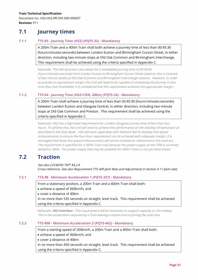
7.1.1 TTS-93 - Journey Time (HS2) (PQTS-32) - Mandatory
A 200m Train and a 400m Train shall both achieve a journey time of less than 00:45:30
(hours:minutes:seconds) between London Euston and Birmingham Curzon Street, in either
direction, including two-minute stops at Old Oak Common and Birmingham Interchange.
This requirement shall be achieved using the criteria specified in Appendix C.
Rationale: The HS2 business case allows for a timetabled journey time of 00:49:00
(hours:minutes:seconds) from London Euston to Birmingham Curzon Street stations; this is inclusive
of two-minute dwells at Old Oak Common and Birmingham Interchange stations. However, in order
to provide an operational margin, the Unit will need to be capable of completing the journey in less
time than that timetabled. It is considered that this requirement achieves the appropriate margin.
7.1.2 TTS-94 - Journey Time (HS2+CRN, 200m) (PQTS-34) - Mandatory
A 200m Train shall achieve a journey time of less than 03:45:30 (hours:minutes:seconds)
between London Euston and Glasgow Central, in either direction, including two-minute
stops at Old Oak Common and Preston. This requirement shall be achieved using the
criteria specified in Appendix C.
Rationale: HS2 has a high-level requirement for London-Glasgow journey time of less than four
hours. To achieve this, the Unit will need to achieve this performance on the existing infrastructure as
described in the Data Book. HS2 will work separately with Network Rail to develop line-speed
enhancements to ensure the four-hour requirement can be achieved with adequate margin. It is
envisaged that these line-speed enhancements will not be included or referenced in this contract.
The requirement is specified for a 200m Train only because the power supply on the CRN is currently
limited to 300A. The power supply that may be available for 400m Trains is not yet determined.
7.2 Traction
See also LOC&PAS TSI[4] §4.2.8
Cross-reference: See also Requirement TTS-409 (Jerk Rate and Adjustment) in Section 9.11 (Jerk rate)
7.2.1 TTS-98 - Minimum Acceleration 1 (PQTS-327) - Mandatory
From a stationary position, a 200m Train and a 400m Train shall both:
achieve a speed of 360km/h; and
cover a distance of 40km
in no more than 535 seconds on straight, level track. This requirement shall be achieved
using the criteria specified in Appendix C.
Rationale: HS2 interface - This requirement will be necessary to support capacity on the railway.
This is the acceleration required by a Train leaving a station and re-joining the main line.
7.2.2 TTS-908 - Minimum Acceleration 2 (PQTS-462) - Mandatory
From a starting speed of 200km/h, a 200m Train and a 400m Train shall both:
achieve a speed of 360km/h; and
cover a distance of 40km
in no more than 450 seconds on straight, level track. This requirement shall be achieved
using the criteria specified in Appendix C.
Train Technical Specification
Document no.: HS2-HS2-RR-SPE-000-000007
Revision: P11
Page 32
Rationale: HS2 interface - This level of acceleration is required to support the Phase Two timetable
and the required service frequency in the core section of the HS2 Network. This is the acceleration
required for a Train joining the HS2 Network at a junction.
7.2.3 With reference to LOC&PAS TSI[4] Clause 4.2.8.1.2 (5), no residual acceleration at the
maximum service speed of 360km/h is required.
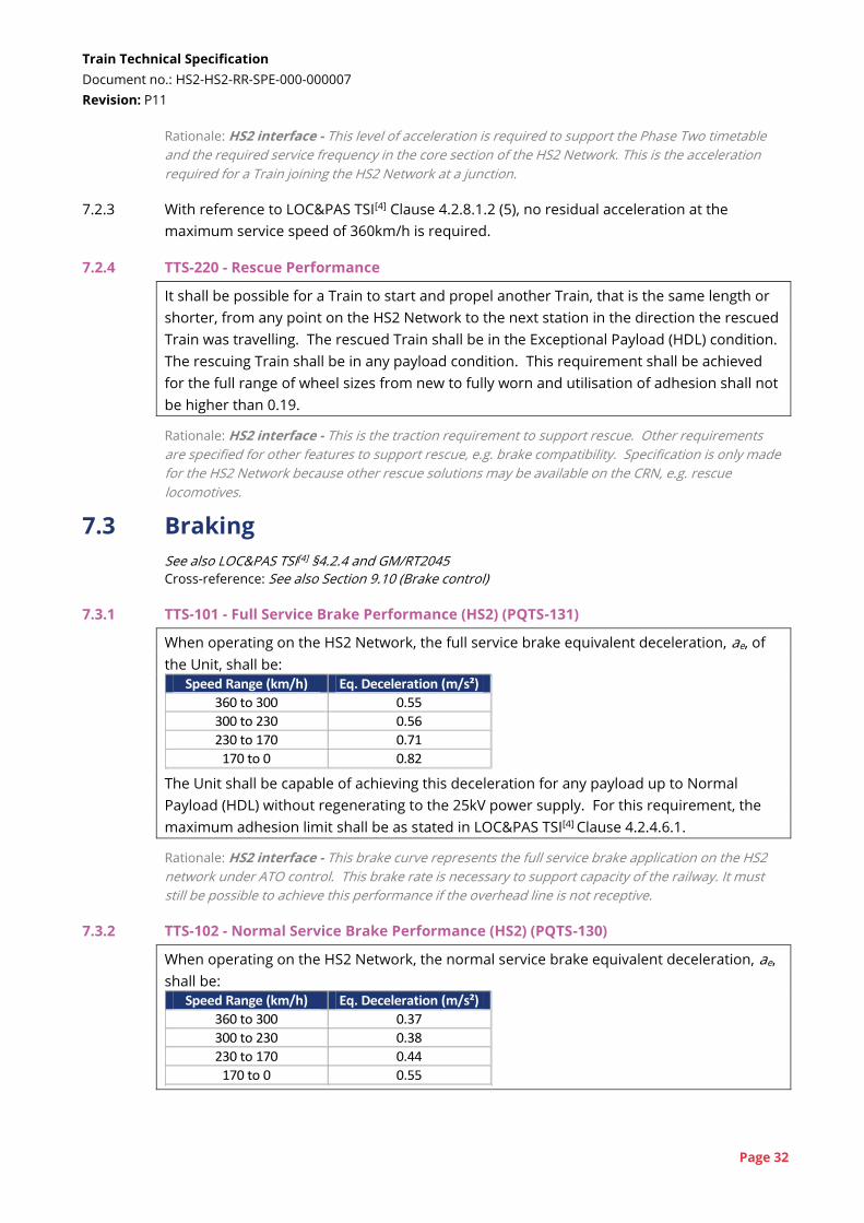
7.2.4 TTS-220 - Rescue Performance
It shall be possible for a Train to start and propel another Train, that is the same length or
shorter, from any point on the HS2 Network to the next station in the direction the rescued
Train was travelling. The rescued Train shall be in the Exceptional Payload (HDL) condition.
The rescuing Train shall be in any payload condition. This requirement shall be achieved
for the full range of wheel sizes from new to fully worn and utilisation of adhesion shall not
be higher than 0.19.
Rationale: HS2 interface - This is the traction requirement to support rescue. Other requirements
are specified for other features to support rescue, e.g. brake compatibility. Specification is only made
for the HS2 Network because other rescue solutions may be available on the CRN, e.g. rescue
locomotives.
7.3 Braking
See also LOC&PAS TSI[4] §4.2.4 and GM/RT2045
Cross-reference: See also Section 9.10 (Brake control)
7.3.1 TTS-101 - Full Service Brake Performance (HS2) (PQTS-131)
When operating on the HS2 Network, the full service brake equivalent deceleration, ae, of
the Unit, shall be:
Speed Range (km/h) Eq. Deceleration (m/s²)
360 to 300 0.55
300 to 230 0.56
230 to 170 0.71
170 to 0 0.82 The Unit shall be capable of achieving this deceleration for any payload up to Normal
Payload (HDL) without regenerating to the 25kV power supply. For this requirement, the
maximum adhesion limit shall be as stated in LOC&PAS TSI[4] Clause 4.2.4.6.1.
Rationale: HS2 interface - This brake curve represents the full service brake application on the HS2
network under ATO control. This brake rate is necessary to support capacity of the railway. It must
still be possible to achieve this performance if the overhead line is not receptive.
7.3.2 TTS-102 - Normal Service Brake Performance (HS2) (PQTS-130)
When operating on the HS2 Network, the normal service brake equivalent deceleration, ae,
shall be:
Speed Range (km/h) Eq. Deceleration (m/s²)
360 to 300 0.37
300 to 230 0.38
230 to 170 0.44
170 to 0 0.55
Train Technical Specification
Document no.: HS2-HS2-RR-SPE-000-000007
Revision: P11
Page 33
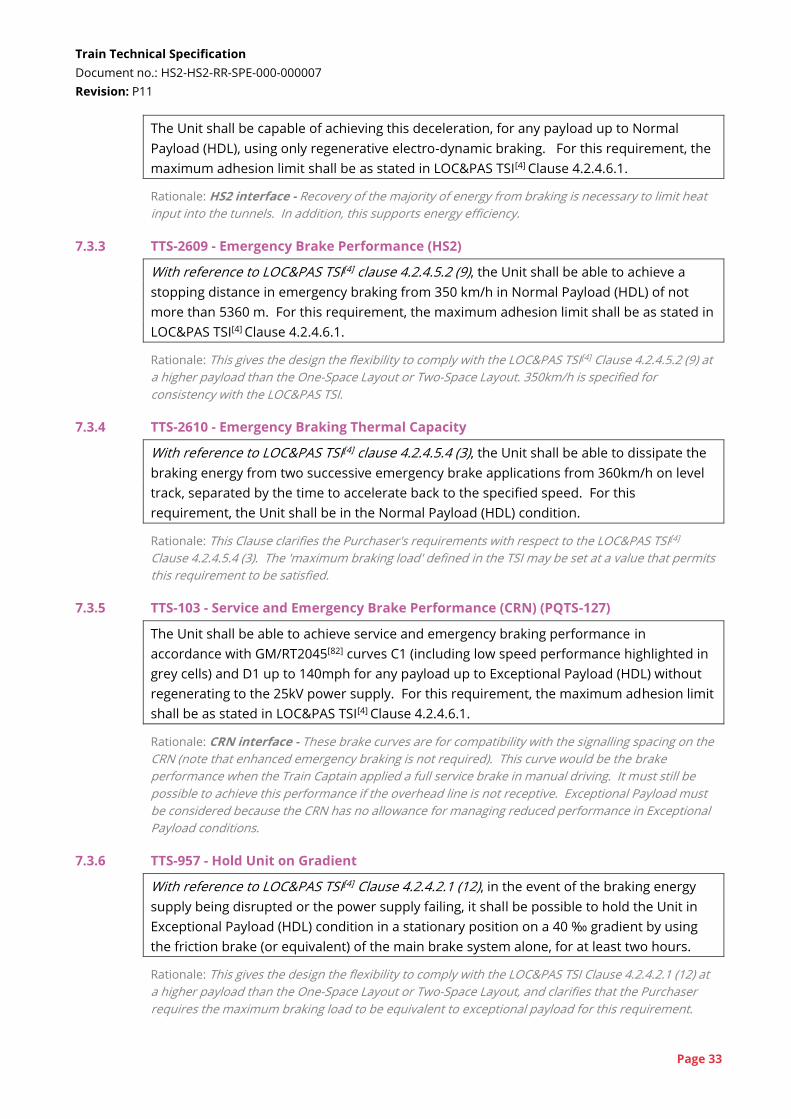
The Unit shall be capable of achieving this deceleration, for any payload up to Normal
Payload (HDL), using only regenerative electro-dynamic braking. For this requirement, the
maximum adhesion limit shall be as stated in LOC&PAS TSI[4] Clause 4.2.4.6.1.
Rationale: HS2 interface - Recovery of the majority of energy from braking is necessary to limit heat
input into the tunnels. In addition, this supports energy efficiency.
7.3.3 TTS-2609 - Emergency Brake Performance (HS2)
With reference to LOC&PAS TSI[4] clause 4.2.4.5.2 (9), the Unit shall be able to achieve a
stopping distance in emergency braking from 350 km/h in Normal Payload (HDL) of not
more than 5360 m. For this requirement, the maximum adhesion limit shall be as stated in
LOC&PAS TSI[4] Clause 4.2.4.6.1.
Rationale: This gives the design the flexibility to comply with the LOC&PAS TSI[4] Clause 4.2.4.5.2 (9) at
a higher payload than the One-Space Layout or Two-Space Layout. 350km/h is specified for
consistency with the LOC&PAS TSI.
7.3.4 TTS-2610 - Emergency Braking Thermal Capacity
With reference to LOC&PAS TSI[4] clause 4.2.4.5.4 (3), the Unit shall be able to dissipate the
braking energy from two successive emergency brake applications from 360km/h on level
track, separated by the time to accelerate back to the specified speed. For this
requirement, the Unit shall be in the Normal Payload (HDL) condition.
Rationale: This Clause clarifies the Purchaser's requirements with respect to the LOC&PAS TSI[4]
Clause 4.2.4.5.4 (3). The 'maximum braking load' defined in the TSI may be set at a value that permits
this requirement to be satisfied.
7.3.5 TTS-103 - Service and Emergency Brake Performance (CRN) (PQTS-127)
The Unit shall be able to achieve service and emergency braking performance in
accordance with GM/RT2045[82] curves C1 (including low speed performance highlighted in
grey cells) and D1 up to 140mph for any payload up to Exceptional Payload (HDL) without
regenerating to the 25kV power supply. For this requirement, the maximum adhesion limit
shall be as stated in LOC&PAS TSI[4] Clause 4.2.4.6.1.
Rationale: CRN interface - These brake curves are for compatibility with the signalling spacing on the
CRN (note that enhanced emergency braking is not required). This curve would be the brake
performance when the Train Captain applied a full service brake in manual driving. It must still be
possible to achieve this performance if the overhead line is not receptive. Exceptional Payload must
be considered because the CRN has no allowance for managing reduced performance in Exceptional
Payload conditions.
7.3.6 TTS-957 - Hold Unit on Gradient
With reference to LOC&PAS TSI[4] Clause 4.2.4.2.1 (12), in the event of the braking energy
supply being disrupted or the power supply failing, it shall be possible to hold the Unit in
Exceptional Payload (HDL) condition in a stationary position on a 40 ‰ gradient by using
the friction brake (or equivalent) of the main brake system alone, for at least two hours.
Rationale: This gives the design the flexibility to comply with the LOC&PAS TSI Clause 4.2.4.2.1 (12) at
a higher payload than the One-Space Layout or Two-Space Layout, and clarifies that the Purchaser
requires the maximum braking load to be equivalent to exceptional payload for this requirement.
Train Technical Specification
Document no.: HS2-HS2-RR-SPE-000-000007
Revision: P11
Page 34
7.3.7 TTS-1058 - Low Adhesion Braking Performance
Braking performance of the Unit shall be maximised in low adhesion conditions that are
likely to be experienced on the CRN.
Rationale: The CRN particularly suffers from low adhesion in autumn, due to the impact of leaf-fall.
WSP and sanding systems are required to manage the levels of adhesion. No particular provisions
for low adhesion are required for the HS2 Network, beyond compliance with LOC&PAS TSI[4] section
4.2.4.6.2.
Cross-reference: See also Requirement TTS-824 (Sanding Equipment) in Section 9.12 (Sanding and
adhesion control)
7.3.8 TTS-958 - Adhesion-independent Braking Systems
The Unit shall not incorporate a track brake or eddy current brake.
Rationale: HS2 and CRN interface - Track brakes and eddy current brakes are not commonly used
on the UK Main Line Network, and their use is not under active consideration on HS2 Network.
7.4 EMC
7.4.1 Overall EMC
7.4.1.1 TTS-1422 - EMC Standards
The Unit shall comply with EN 50121-3-1[57] [59] and EN 50121-3-2[58] [60], i.e. the 2006 and
2016/2017 versions of this standard.
Rationale: HS2 and CRN interface - The HS2 Infrastructure Manager have overall responsibility for
compatibility with respect to EMC on the HS2 Network. The TMM must meet this EuroNorm to
support compatibility. Compliance also supports compatibility with the CRN. Compliance is required
with a composite frequency range from both versions of the standard. The 2016 versions are
required for the high frequency (>1GHz) radiated emission and immunity test limits as this is a
credible hazard due to the proliferation of mobile communication devices operating in these higher
frequency bands. Compliance with the 2006 versions is required for compatibility with Network Rail
infrastructure.
7.4.1.2 TTS-106 - EMC (CRN) (PQTS-330) - Mandatory
Electromagnetic emissions from a Train shall be limited to levels that will not create a
hazard to the safe operation of infrastructure systems and equipment, or other existing
rolling stock on the CRN.
The Unit shall be immune to electromagnetic emissions from infrastructure systems and
equipment, and other existing rolling stock on the CRN.
Rationale: CRN interface - Achieving this requirement supports compatibility with the CRN.
Responsibility for EMC with the CRN is allocated to the TMM. The Train will need to be compatible
with legacy infrastructure systems including power supply, signalling and communications, which
may not meet modern standards. Additional equipment may be required to prevent interference.
7.4.1.3 TTS-107 - EMC (Neighbouring Railways) (PQTS-411) - Mandatory
Electromagnetic emissions from a Train shall be limited to levels that will not create a
hazard to the safe operation of infrastructure systems and equipment, or other existing
rolling stock on neighbouring railways.
Train Technical Specification
Document no.: HS2-HS2-RR-SPE-000-000007
Revision: P11
Page 35
The Unit shall be immune to electromagnetic emissions from infrastructure systems and
equipment, and other existing rolling stock on neighbouring railways.
Rationale: CRN interface - Achieving this requirement supports compatibility with the neighbouring
railways. Responsibility for EMC with neighbouring railways, where this is due to the Train, is
allocated to the TMM. HS2 services will run in proximity to a number of other rail systems, including
London Underground, Manchester Metrolink, Glasgow Subway and other parts of Network Rail
infrastructure that do not form part of the CRN. As for the CRN, systems on these networks may not
meet modern standards.
7.4.2 Mobile telephone use
7.4.2.1 TTS-1484 - Mobile Telephone Compatibility
The Unit shall not cause excessive impediment to mobile telephones and other similar
devices communicating with public networks.
Rationale: Some recent rolling stock introduced in the UK has had characteristics that interfere with
mobile phone signals. This interference should be minimised as far as possible.
7.5 Energy collection
7.5.1 Electrical power supply See also LOC&PAS TSI[4] §4.2.8.2 and GM/RT2111[84]
7.5.1.1 TTS-802 - Power Supply - Definition
With reference to LOC&PAS TSI[4] Clause 4.2.8.2.1 (2), the Unit shall comply with the
requirements for the AC 25 kV 50 Hz system only.
Rationale: HS2 and CRN interface - Compatibility with other power supply voltages / frequencies
(e.g. 750V DC) listed in the TSI is not required.
7.5.1.2 TTS-1488 - Power Supply Compatibility (HS2)
The Unit shall comply with EN 50388[64] for a 25kV system.
Rationale: HS2 interface - The TMM's responsibility for electrical compatibility with the HS2 Network
power supply will be to comply with this standard. Note that it will also be necessary to apply this
standard for compatibility with the CRN (TTS-1487).
7.5.1.3 TTS-3348 - Power Factor (HS2)
With reference to EN 50388[64] Clause 6.2, for line voltage below Umax1 and regardless of the
active power flow direction, inductive displacement power factor shall be above 0.95.
Rationale: HS2 interface - This requirement is based on the requirement contained in prEN 50388-
1[64A] and has been used in the specification of the HS2 power supply. It should be understood that
during regeneration the power factor can only be allowed to decrease freely in the range of 1.1Un
and Umax2 in order to keep voltage within limits.
7.5.1.4 TTS-1487 - Power Supply Compatibility (CRN)
The Unit shall be compatible with the 25kV power supply systems on the CRN.
Train Technical Specification
Document no.: HS2-HS2-RR-SPE-000-000007
Revision: P11
Page 36
Rationale: CRN interface - The TMM will have full responsibility for electrical compatibility with the
CRN power supply. This will include compliance with applicable standards and compatibility with
specific features of the CRN routes.
7.5.1.5 TTS-2485 - Shore Supply Plug/Socket Arrangement
The Unit shall be compatible with a 400V power supply defined in LOC&PAS TSI[4] Clause
4.2.11.6 and EN/IEC 60309-2[68].
There shall be connections for this power supply at the ends of the Unit, in the vicinity of
the auto-coupler.
Rationale: Depot interface - This is to enable auxiliary supply when the pantograph cannot be raised.
This is only required at the home depot of the Unit, since it is assumed Units will remain powered via
pantographs when stabled elsewhere on the network. A position at the end of the Unit is specified to
give the capability to provide auxiliary power from a locomotive.
7.5.1.6 TTS-3484 - Shore Supply Electrical Separation
It shall be possible to plug the shore supply in at only one end of a Unit or at both ends of a
Unit. In the case that the shore supply is plugged in at both ends of the Unit, suitable
automatic electrical separation shall be provided to mitigate the effects of asynchronous
power supplies within the depot.
Rationale: Depot interface - It is understood that the shore supply sockets specified in EN/IEC 60309-
2 may not be suitably rated to supply the entirety of the auxiliary load on a 200m Unit. Therefore, the
ability to plug in a second shore supply at the other end of the Unit will allow a higher auxiliary load
to be drawn by the Unit. It is noted that with both shore supplies plugged in, the full auxiliary load of
the Unit may still not be able to be drawn.
7.5.2 Pantograph See also LOC&PAS TSI[4] §4.2.8.2.9 and GM/RT2111[84]
7.5.2.1 The following requirements refer to an HS2 Pantograph for the pantograph that will be
used on the HS2 Network and a CRN Pantograph for a pantograph that will be used on
the CRN. The Unit could be fitted with different types of pantograph for each network, or a
single type of pantograph that complies with all the requirements for both the HS2
Pantograph and CRN Pantograph. However, a single type of pantograph that would satisfy
all of the requirements below has not been identified, so it is assumed that two different
types of pantograph will be fitted. It is further assumed that two of each pantograph type
will be provided for redundancy, though this is also not specifically required.
7.5.2.2 TTS-398 - OCS Height Range (HS2)
With reference to LOC&PAS TSI[4] Section 4.2.8.2.9.1.1, the installation and movement range
of the HS2 Pantograph shall allow mechanical contact with a contact wire at a height of
5.12m above rail level.
Rationale: HS2 interface - This requirement for the HS2 Network is less onerous than LOC&PAS TSI[4]
Clause 4.2.8.2.9.1.1, since the HS2 contact wire will be installed at a constant height (with
construction tolerance). The wire will be installed at a nominal height at registration arms of 5.12m.
More detailed design information for the OCS is given in document HS2-HS2-RR-REP-000-000056[120].
The Purchaser would support an 'innovative solution' or other approach to permit the HS2
Train Technical Specification
Document no.: HS2-HS2-RR-SPE-000-000007
Revision: P11
Page 37
Pantograph to only operate over a reduced height range and not comply with the LOC&PAS TSI
Clause 4.2.8.2.9.1.1. Note that wire height at Washwood Heath depot may be at a different height.
7.5.2.3 TTS-397 - OLE Low Height Limit (CRN)
With reference to Clause 4.5.1 of GM/RT2111[84], the Unit and the CRN Pantograph shall be
compatible with a low wire height of 4.140m above rail level.
Rationale: CRN interface - This minimum height limit has been defined from data provided by
Network Rail. This data shows a number of low wire heights below the nominal minimum in RGS of
4.165m. Stagger is shown by the data to be compliant with NR/L2/ELP/21088[108].
7.5.2.4 TTS-399 - Pantograph Spacing (HS2)
With reference to LOC&PAS TSI [4] Clause 4.2.8.2.9.7 (3), on a 400m Train, the separation
between two active HS2 Pantographs shall be at least 200m.
Rationale: HS2 interface - The HS2 Network's overhead line equipment will be compliant with the
ENE TSI[8] and designed for 200m spacing. If a single HS2 Pantograph was fitted to each Unit, this
requirement would not be achieved, because the orientation of Units will frequently change in
service. Additional analysis of compatibility with the OCS would be required at the reduced spacing,
and the TMM would be responsible for compatibility as described in MSA Schedule 11.
7.5.2.5 TTS-990 - Pantograph Head Geometry (HS2)
With reference to LOC&PAS TSI[4] Clause 4.2.8.2.9.2 (1), the head geometry for HS2
Pantograph shall comply with EN 50367[63] Figure A.6.
Rationale: HS2 interface - This is one of the two geometries permitted by LOC&PAS TSI §4.2.8.2.9.2.
The HS2 Network has been designed for this geometry and not the wider 1950mm head.
7.5.2.6 The head geometry for the CRN Pantograph is defined as a notified national technical rule
to be EN 50367[63] Figure B.6. The head geometry defined in Figure A.6 is also permitted if
this is compatible, but this is considered unlikely to be compatible with the CRN due to this
profile's insulated horns.
7.5.2.7 TTS-401 - Contact Quality (HS2)
With reference to LOC&PAS TSI[4] Section 4.2.8.2.9.6, on both a 200m Train and a 400m
Train, the HS2 Pantograph contact force and dynamic behaviour shall comply with the
criteria of ENE TSI[8] Table 4.2.12 applied at 360km/h while operating on the HS2 Network.
The HS2 Network's OCS is characterised by design document HS2-HS2-RR-REP-000-
000056[120].
Rationale: HS2 interface - The referenced document provides initial information about the OCS, that
will be refined during the design development phases of the Unit and OCS, and integration of the two
systems in accordance with MSA Schedule 11. This OCS is designed to enable the ENE TSI criteria to
be applied at 360km/h, instead of the 320km/h limit specified in the TSI.
7.5.2.8 The CRN contact force and dynamic behaviour criteria are specified in GM/RT2111[84]
section 4.9.1 which defines a set of CRN Contact Quality Criteria.
7.5.2.9 The following requirements are based on these criteria and standards.
Train Technical Specification
Document no.: HS2-HS2-RR-SPE-000-000007
Revision: P11
Page 38
7.5.2.10 TTS-402 - Contact Quality (CRN, 200m Train)
On a 200m Train, the CRN Pantograph shall meet the CRN Contact Quality Criteria when
operating over any part of the CRN at any speed up to the Maximum Line Speed.
Rationale: CRN interface - Operation of a single Unit with a single pantograph up to the Maximum
Line Speed is achieved by current rolling stock on the WCML and ECML, and so is considered
achievable by the Unit.
7.5.2.11 TTS-2856 - Contact Quality (CRN, 400m Train 100mph)
On a 400m Train, both CRN Pantographs shall meet the CRN Contact Quality Criteria when
operating over any part of the CRN at any speed up to 100mph or Maximum Line Speed,
whichever is lower.
Rationale: CRN interface - Operation of a multiple units at 100mph is achieved by current rolling
stock on the WCML and ECML using shorter pantograph spacing than is likely to be achieved with the
HS2 Units. Therefore, this requirement is considered achievable by the HS2 Unit.
7.5.2.12 TTS-2857 - Contact Quality (CRN, 400m Train, 125mph)
The TMM shall use reasonable endeavours to procure that on a 400m Train, both CRN
Pantographs shall meet the CRN Contact Quality Criteria when operating over any part of
the CRN at any speed up to Maximum Line Speed.
Rationale: CRN interface - Operation of multiple units above 100mph has been investigated on a
number of projects. Some units have been authorised for operation at 110mph on some sections of
the WCML. A 400m Unit should achieve much larger pantograph spacing than trains of existing units,
and improvements in pantograph design may permit this requirement to be achieved wholly or
partially.
7.5.2.13 The CRN OLE is defined by NR/L2/ELP/21088[108].
7.5.2.14 There is no requirement for the width (along the track) of the HS2 Pantograph other than
that in the LOC&PAS TSI[4]; a single carbon solution would be acceptable.
7.6 Energy consumption
7.6.1 Energy consumption requirements have been set to manage significant parts of the long-
term cost and environmental impact of operating the Unit.
Cross-reference: See also Requirement-Intro TTS-847 (Greenhouse Gas Emissions during Lifecycle) in
Section 7.20 (Environmental impact)
7.6.2 TTS-115 - HS2 1SL Energy Consumption (PQTS-49)
When operating on the HS2 Network, the average energy consumption of the Unit shall not
exceed [●] kWh/Unit/km when calculated in accordance with the criteria specified in
Appendix C and assuming the Normal Payload (1SL).
7.6.3 TTS-3327 - HS2 2SL Energy Consumption
When operating on the HS2 Network, the average energy consumption of the Unit shall not
exceed [●] kWh/Unit/km when calculated in accordance with the criteria specified in
Appendix C and assuming the Normal Payload (2SL).
Train Technical Specification
Document no.: HS2-HS2-RR-SPE-000-000007
Revision: P11
Page 39
7.6.4 TTS-1921 - CRN 1SL Energy Consumption
When operating on CRN, the average energy consumption of the Unit shall not exceed [●]
kWh/Unit/km when calculated in accordance with the criteria specified in Appendix C and
assuming the Normal Payload (1SL).
7.6.5 TTS-3328 - CRN 2SL Energy Consumption
When operating on CRN, the average energy consumption of the Unit shall not exceed [●]
kWh/Unit/km when calculated in accordance with the criteria specified in Appendix C and
assuming the Normal Payload (2SL).
Rationale: Separate targets are set for the HS2 Network and the CRN because the operation, in
particular speed, will be quite different on the two infrastructures.
7.6.6 TTS-1923 - Annual Average Auxiliary Consumption 1SL
The Unit shall not exceed an average auxiliary consumption of [●] kW when calculated in
accordance with the criteria and Energy Assessment Tool in Appendix C and assuming the
Normal Payload (1SL).
7.6.7 TTS-3330 - Annual Average Auxiliary Consumption 2SL
The Unit shall not exceed an average auxiliary consumption of [●] kW when calculated in
accordance with the criteria and Energy Assessment Tool in Appendix C and assuming the
Normal Payload (2SL).
Rationale: A further separate requirement is specified for auxiliary consumption to account for its
relatively small proportion compared to traction consumption, and to enable assessment at all times
of the year.
7.6.8 Update for contract - The missing values in requirements TTS-115, TTS-3327, TTS-1921,
TTS-3328, TTS-1923 and TTS-3330 will be populated in the contracted version of the TTS
using values provided for Stage 5 of the Tender Evaluation.
7.6.9 TTS-3169 - Power Consumption - Standby State
The energy consumption of the Unit when in the Standby State shall be minimised.
Rationale: This requirement is intended to define that when Units are stabled, their consumption
should be reduced to as low a level as possible while protecting the Unit and allowing it to return to
service within a reasonable timeframe. It is intended that the full definition of which consumers
operate at reduced power will be finalised during the design phase.
7.7 Auxiliary Power Supply
7.7.1 TTS-815 - Maintain Power through Transitions
Following a loss of 25kV power supply at neutral sections and the HS2-CRN transition, the
Auxiliary Power Supply shall maintain full supply to all non-traction systems for at least 30
seconds, provided that the Unit is moving faster than 60km/h.
There may be short interruptions to power supply provided that these are not discernible
to Passengers.
Train Technical Specification
Document no.: HS2-HS2-RR-SPE-000-000007
Revision: P11
Page 40
Rationale: This requirement is to cover neutral sections and the transition between HS2 and the CRN.
To avoid disruption to passengers, HS2 requires HVACs to continue to operate during the transition.
7.7.2 TTS-1726 - 10-Minute Auxiliary Supply
Following an unplanned loss of 25kV power supply, the Auxiliary Power Supply shall
maintain all passenger-facing systems, except
heating;
cooling;
catering systems; and
at-seat power sockets
at the same performance as before the power loss, for at least 10 minutes.
This shall be achieved at any external ambient temperature between -5°C and 30°C.
Rationale: As far as possible, the Unit should maintain normal performance in the initial stages of
disruption.
7.7.3 TTS-3248 - 60-Minute Auxiliary Supply
Following an unplanned loss of 25kV power supply, the Auxiliary Power Supply shall
maintain supply to the following systems and functions for at least 60 minutes:
ventilation for all parts of the Unit; and
reduced lighting level.
This shall be achieved at any external ambient temperature between -5°C and 30°C.
Rationale: This supply is to maintain an acceptable passenger environment in the event of a loss of
25kV supply. The one hour duration is specified to ensure there is ventilation during an evacuation,
which is predicted to take longer than 30 minutes that is specified for ventilation in the LOC&PAS
TSI[4].
Cross-reference: See also Requirement TTS-388 (CO2 Level - Emergency) in Section 7.16.1 (Saloon
climate)
See also Section 10.20.4 (Reduced lighting)
7.7.4 TTS-1176 - 180-Minute Auxiliary Supply
Following an unplanned loss of 25kV power supply, the Auxiliary Power Supply shall
maintain supply to the following systems and functions for at least 180 minutes:
train control including all displays in the Cab and at the Crew Control Point;
train protection systems;
external lights;
emergency lighting;
voice communication between Passengers, Train Captain, Train Crew and the Wayside;
ten minutes of all passenger information colour display operation at any time within the
180 minutes;
PEAs and call-for-aid devices;
10 cycles of Internal Doors;
2 cycles of External Doors and Moveable Steps;
all CCTV and 10 minutes continuous transmission to the Wayside upon request; and
10 cycles of the Toilets and all Passenger-facing Sanitary Systems.
This shall be achieved at any external ambient temperature between -5°C and 30°C.
Train Technical Specification
Document no.: HS2-HS2-RR-SPE-000-000007
Revision: P11
Page 41
Rationale: This supply is to maintain an emergency passenger environment and sufficient
functionality in the event of a loss of 25kV supply. With respect to Toilets and Sanitary Systems,
Passengers must be able to use the Toilet and Sanitary Systems for two hours. Effluent-management
systems may be loadshed provided this does not restrict use of the Toilet. A number of cycles or
duration is specified to allow sizing of the Auxiliary Power Supply - it is assumed that any number of
cycles can be achieve in practice while there is still sufficient supply.
7.7.5 TTS-2612 - 5-hour Auxiliary Supply
Following an unplanned loss of 25kV power supply, the Auxiliary Power Supply shall
maintain the following functions for at least five hours:
tail lights;
any power necessary to enable coupling (e.g. coupler cover);
any power necessary to enable brake control via the brake pipe (TTS-820); and
any power necessary to control traction and braking of a rescuing Unit from the Cab of
the failed Unit (TTS-3415).
This shall be achieved at any external ambient temperature between -5°C and 30°C.
Rationale: This is to provide sufficient power to enable rescue to be undertaken. In this scenario,
Passengers would no longer be on-board
7.7.6 Note that TTS-1726, TTS-1176 and TTS-2612 should be considered to start at the same time
and hence overlap, rather than starting sequentially.
7.7.7 TTS-1174 - Future Flexibility - Additional Auxiliary Capacity
The Auxiliary Power Supply shall enable new systems and equipment to be installed
through the Unit's life. The Auxiliary Power Supply shall have a minimum of 10% additional
capacity above the level necessary to deliver the performance and functions specified in
this TTS for the 2SL, considering the normal range of operation. 10% additional capacity
shall be available for both AC and DC supplies.
Rationale: This additional capacity is specified to enable new systems to be added to the Unit during
the design process or during future refurbishment.
7.7.8 TTS-2475 - Future Flexibility - Additional Electrical Storage Capacity
The Auxiliary Power Supply shall have a minimum of 10% electrical storage above the level
necessary to deliver requirements TTS-1726, TTS-1176, TTS-2612 and TTS-3248 for the 2SL.
7.7.9 Note that where the collaboration processes defined in MSA Schedule 9, Appendix 1 lead
to changes to on-board power consumption, the TMM will need to report any impact on
compliance with TTS-1174 and TTS-2475, and any other TTS requirements, which would be
resolved via a Purchaser Change.
7.8 Structural integrity and Carbody
See also LOC&PAS TSI[4] §4.2.2, GM/RT2100[83] and guidance note GM/GN2686[97]
7.8.1 Requirements for Window and deadlight size and position are specified in Section 11.1.3.
These requirements will affect the Carbody design and its structural integrity.
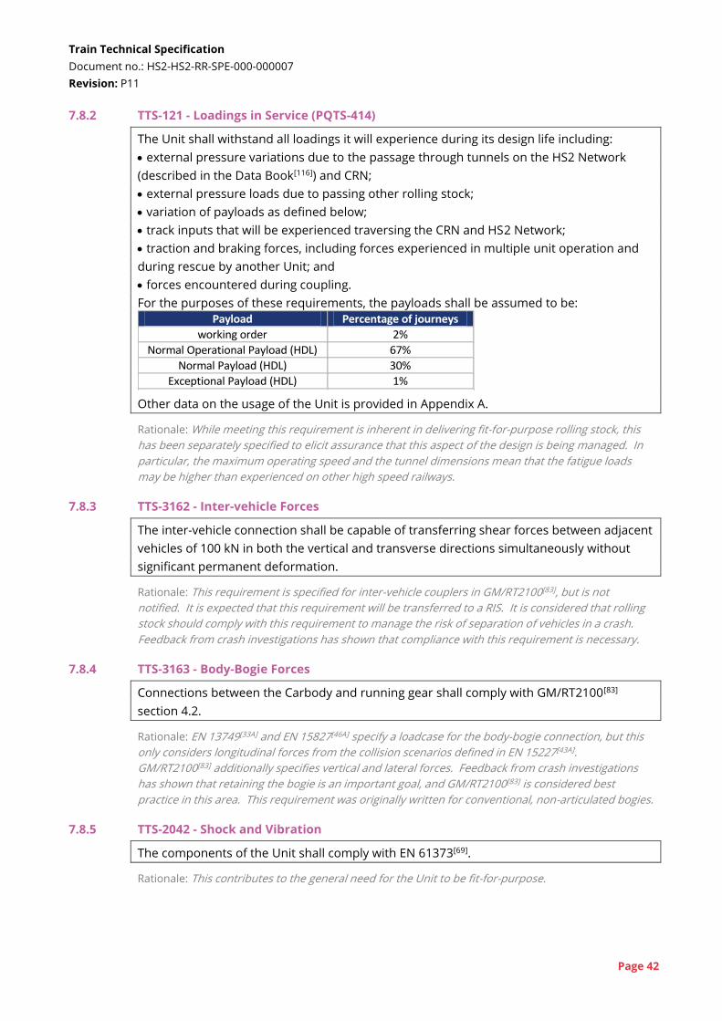
Train Technical Specification
Document no.: HS2-HS2-RR-SPE-000-000007
Revision: P11
Page 42
7.8.2 TTS-121 - Loadings in Service (PQTS-414)
The Unit shall withstand all loadings it will experience during its design life including:
external pressure variations due to the passage through tunnels on the HS2 Network
(described in the Data Book[116]) and CRN;
external pressure loads due to passing other rolling stock;
variation of payloads as defined below;
track inputs that will be experienced traversing the CRN and HS2 Network;
traction and braking forces, including forces experienced in multiple unit operation and
during rescue by another Unit; and
forces encountered during coupling.
For the purposes of these requirements, the payloads shall be assumed to be:
Payload Percentage of journeys
working order 2%
Normal Operational Payload (HDL) 67%
Normal Payload (HDL) 30%
Exceptional Payload (HDL) 1% Other data on the usage of the Unit is provided in Appendix A.
Rationale: While meeting this requirement is inherent in delivering fit-for-purpose rolling stock, this
has been separately specified to elicit assurance that this aspect of the design is being managed. In
particular, the maximum operating speed and the tunnel dimensions mean that the fatigue loads
may be higher than experienced on other high speed railways.
7.8.3 TTS-3162 - Inter-vehicle Forces
The inter-vehicle connection shall be capable of transferring shear forces between adjacent
vehicles of 100 kN in both the vertical and transverse directions simultaneously without
significant permanent deformation.
Rationale: This requirement is specified for inter-vehicle couplers in GM/RT2100[83], but is not
notified. It is expected that this requirement will be transferred to a RIS. It is considered that rolling
stock should comply with this requirement to manage the risk of separation of vehicles in a crash.
Feedback from crash investigations has shown that compliance with this requirement is necessary.
7.8.4 TTS-3163 - Body-Bogie Forces
Connections between the Carbody and running gear shall comply with GM/RT2100[83]
section 4.2.
Rationale: EN 13749[33A] and EN 15827[46A] specify a loadcase for the body-bogie connection, but this
only considers longitudinal forces from the collision scenarios defined in EN 15227[43A].
GM/RT2100[83] additionally specifies vertical and lateral forces. Feedback from crash investigations
has shown that retaining the bogie is an important goal, and GM/RT2100[83] is considered best
practice in this area. This requirement was originally written for conventional, non-articulated bogies.
7.8.5 TTS-2042 - Shock and Vibration
The components of the Unit shall comply with EN 61373[69].
Rationale: This contributes to the general need for the Unit to be fit-for-purpose.
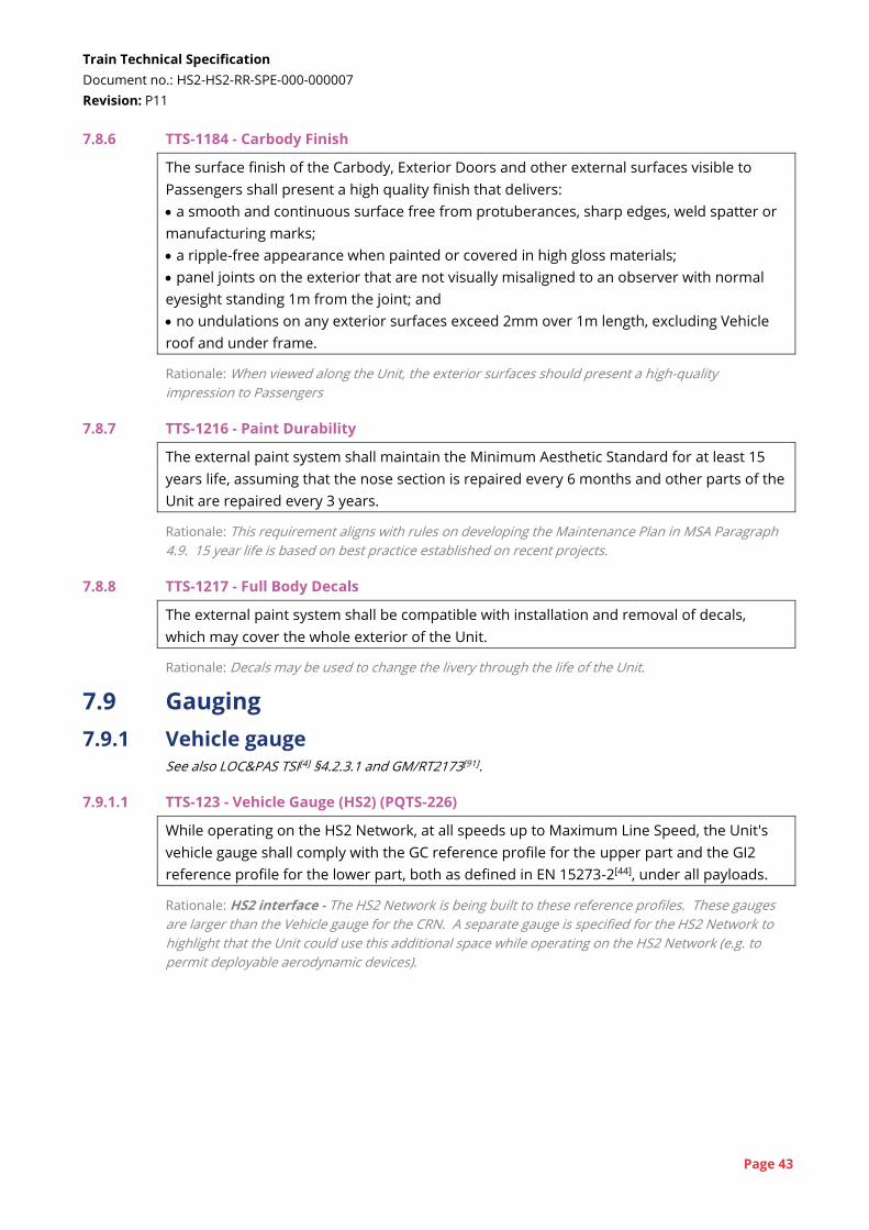
Train Technical Specification
Document no.: HS2-HS2-RR-SPE-000-000007
Revision: P11
Page 43
7.8.6 TTS-1184 - Carbody Finish
The surface finish of the Carbody, Exterior Doors and other external surfaces visible to
Passengers shall present a high quality finish that delivers:
a smooth and continuous surface free from protuberances, sharp edges, weld spatter or
manufacturing marks;
a ripple-free appearance when painted or covered in high gloss materials;
panel joints on the exterior that are not visually misaligned to an observer with normal
eyesight standing 1m from the joint; and
no undulations on any exterior surfaces exceed 2mm over 1m length, excluding Vehicle
roof and under frame.
Rationale: When viewed along the Unit, the exterior surfaces should present a high-quality
impression to Passengers
7.8.7 TTS-1216 - Paint Durability
The external paint system shall maintain the Minimum Aesthetic Standard for at least 15
years life, assuming that the nose section is repaired every 6 months and other parts of the
Unit are repaired every 3 years.
Rationale: This requirement aligns with rules on developing the Maintenance Plan in MSA Paragraph
4.9. 15 year life is based on best practice established on recent projects.
7.8.8 TTS-1217 - Full Body Decals
The external paint system shall be compatible with installation and removal of decals,
which may cover the whole exterior of the Unit.
Rationale: Decals may be used to change the livery through the life of the Unit.
7.9 Gauging
7.9.1 Vehicle gauge See also LOC&PAS TSI[4] §4.2.3.1 and GM/RT2173[91].
7.9.1.1 TTS-123 - Vehicle Gauge (HS2) (PQTS-226)
While operating on the HS2 Network, at all speeds up to Maximum Line Speed, the Unit's
vehicle gauge shall comply with the GC reference profile for the upper part and the GI2
reference profile for the lower part, both as defined in EN 15273-2[44], under all payloads.
Rationale: HS2 interface - The HS2 Network is being built to these reference profiles. These gauges
are larger than the Vehicle gauge for the CRN. A separate gauge is specified for the HS2 Network to
highlight that the Unit could use this additional space while operating on the HS2 Network (e.g. to
permit deployable aerodynamic devices).
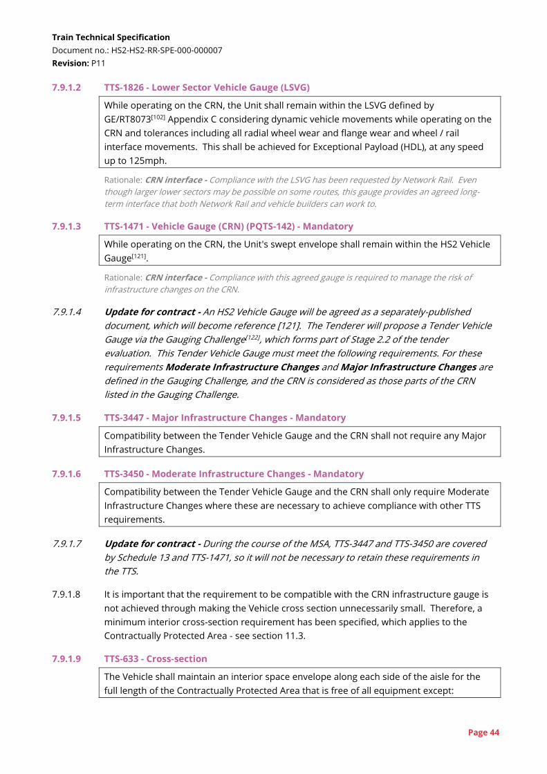
Train Technical Specification
Document no.: HS2-HS2-RR-SPE-000-000007
Revision: P11
Page 44
7.9.1.2 TTS-1826 - Lower Sector Vehicle Gauge (LSVG)
While operating on the CRN, the Unit shall remain within the LSVG defined by
GE/RT8073[102] Appendix C considering dynamic vehicle movements while operating on the
CRN and tolerances including all radial wheel wear and flange wear and wheel / rail
interface movements. This shall be achieved for Exceptional Payload (HDL), at any speed
up to 125mph.
Rationale: CRN interface - Compliance with the LSVG has been requested by Network Rail. Even
though larger lower sectors may be possible on some routes, this gauge provides an agreed long-
term interface that both Network Rail and vehicle builders can work to.
7.9.1.3 TTS-1471 - Vehicle Gauge (CRN) (PQTS-142) - Mandatory
While operating on the CRN, the Unit's swept envelope shall remain within the HS2 Vehicle
Gauge[121].
Rationale: CRN interface - Compliance with this agreed gauge is required to manage the risk of
infrastructure changes on the CRN.
7.9.1.4 Update for contract - An HS2 Vehicle Gauge will be agreed as a separately-published
document, which will become reference [121]. The Tenderer will propose a Tender Vehicle
Gauge via the Gauging Challenge[122], which forms part of Stage 2.2 of the tender
evaluation. This Tender Vehicle Gauge must meet the following requirements. For these
requirements Moderate Infrastructure Changes and Major Infrastructure Changes are
defined in the Gauging Challenge, and the CRN is considered as those parts of the CRN
listed in the Gauging Challenge.
7.9.1.5 TTS-3447 - Major Infrastructure Changes - Mandatory
Compatibility between the Tender Vehicle Gauge and the CRN shall not require any Major
Infrastructure Changes.
7.9.1.6 TTS-3450 - Moderate Infrastructure Changes - Mandatory
Compatibility between the Tender Vehicle Gauge and the CRN shall only require Moderate
Infrastructure Changes where these are necessary to achieve compliance with other TTS
requirements.
7.9.1.7 Update for contract - During the course of the MSA, TTS-3447 and TTS-3450 are covered
by Schedule 13 and TTS-1471, so it will not be necessary to retain these requirements in
the TTS.
7.9.1.8 It is important that the requirement to be compatible with the CRN infrastructure gauge is
not achieved through making the Vehicle cross section unnecessarily small. Therefore, a
minimum interior cross-section requirement has been specified, which applies to the
Contractually Protected Area - see section 11.3.
7.9.1.9 TTS-633 - Cross-section
The Vehicle shall maintain an interior space envelope along each side of the aisle for the
full length of the Contractually Protected Area that is free of all equipment except:
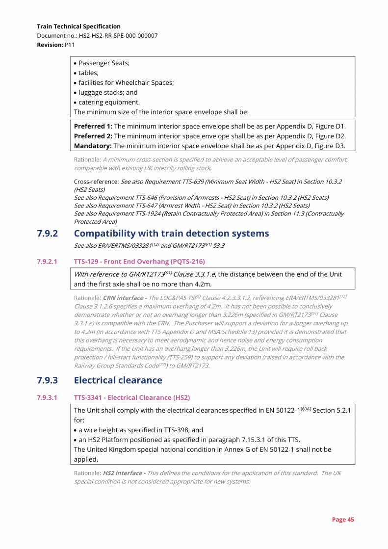
Train Technical Specification
Document no.: HS2-HS2-RR-SPE-000-000007
Revision: P11
Page 45
Passenger Seats;
tables;
facilities for Wheelchair Spaces;
luggage stacks; and
catering equipment.
The minimum size of the interior space envelope shall be:
Preferred 1: The minimum interior space envelope shall be as per Appendix D, Figure D1.
Preferred 2: The minimum interior space envelope shall be as per Appendix D, Figure D2.
Mandatory: The minimum interior space envelope shall be as per Appendix D, Figure D3.
Rationale: A minimum cross-section is specified to achieve an acceptable level of passenger comfort,
comparable with existing UK intercity rolling stock.
Cross-reference: See also Requirement TTS-639 (Minimum Seat Width - HS2 Seat) in Section 10.3.2
(HS2 Seats)
See also Requirement TTS-646 (Provision of Armrests - HS2 Seat) in Section 10.3.2 (HS2 Seats)
See also Requirement TTS-647 (Armrest Width - HS2 Seat) in Section 10.3.2 (HS2 Seats)
See also Requirement TTS-1924 (Retain Contractually Protected Area) in Section 11.3 (Contractually
Protected Area)
7.9.2 Compatibility with train detection systems See also ERA/ERTMS/033281[12] and GM/RT2173[91] §3.3
7.9.2.1 TTS-129 - Front End Overhang (PQTS-216)
With reference to GM/RT2173[91] Clause 3.3.1.e, the distance between the end of the Unit
and the first axle shall be no more than 4.2m.
Rationale: CRN interface - The LOC&PAS TSI[4] Clause 4.2.3.3.1.2, referencing ERA/ERTMS/033281[12]
Clause 3.1.2.6 specifies a maximum overhang of 4.2m. It has not been possible to conclusively
demonstrate whether or not an overhang longer than 3.226m (specified in GM/RT2173[91] Clause
3.3.1.e) is compatible with the CRN. The Purchaser will support a deviation for a longer overhang up
to 4.2m (in accordance with TTS Appendix O and MSA Schedule 13) provided it is demonstrated that
this overhang is necessary to meet aerodynamic and hence noise and energy consumption
requirements. If the Unit has an overhang longer than 3.226m, the Unit will require roll back
protection / hill-start functionality (TTS-259) to support any deviation (raised in accordance with the
Railway Group Standards Code[77]) to GM/RT2173.
7.9.3 Electrical clearance
7.9.3.1 TTS-3341 - Electrical Clearance (HS2)
The Unit shall comply with the electrical clearances specified in EN 50122-1[60A] Section 5.2.1
for:
a wire height as specified in TTS-398; and
an HS2 Platform positioned as specified in paragraph 7.15.3.1 of this TTS.
The United Kingdom special national condition in Annex G of EN 50122-1 shall not be
applied.
Rationale: HS2 interface - This defines the conditions for the application of this standard. The UK
special condition is not considered appropriate for new systems.
Train Technical Specification
Document no.: HS2-HS2-RR-SPE-000-000007
Revision: P11
Page 46
7.9.3.2 TTS-2712 - Electrical Clearance (CRN)
The risk to Passengers:
on a nominal CRN platform; and also when
boarding the Unit
due to electrical clearances shall be no worse than for existing rolling stock operating on
the CRN.
Rationale: CRN interface - Although the risks associated with electrical clearance are primarily
defined by the OLE height (outside TMM control) and pantograph profile (set by standards), the
installation of the pantograph and high voltage equipment on the roof can have a relative impact on
safety compared to existing rolling stock. Class 390 and Class 800 are considered to have the highest
risk due to the tapered carbody cross-section profile and position of the bodyside door respectively.
7.10 Mass and static loads
See also GE/RT8006[100]
7.10.1 TTS-911 - Minimum and Maximum Mass and Axle Loads (PQTS-453)
The mass of the Vehicles of the Unit, and the axleload of each axle within the Unit,
calculated in the Normal Payload (HDL) condition, shall be within ±10% of the values
defined in Appendix E.
Rationale: CRN interface - The mass limits and axle load limits are specified for the purpose of
managing compatibility with underline bridges. The values in Appendix E will be used to assess
compatibility and determine any infrastructure changes (at HS2 Ltd's cost) or operational restrictions.
7.10.2 Update for contract - Appendix E is currently blank. It will be populated in the contracted
version of the TTS using values provided in the TMM Train Proposal.
7.10.3 TTS-132 - Maximum Axle Load (PQTS-118)
The maximum axle load of any axle, in Normal Operational Payload (HDL), shall be not
more than 17.0 tonnes.
Rationale: HS2 interface - This is consistent with the INF TSI[9] Table 2, Clause 4.2.1, with previous
high speed design limits and is the interface value for the HS2 Network for the design of the civil
structures and track.
7.10.4 TTS-133 - Maximum Route Availability (PQTS-119)
The Route Availability (RA) value of the Unit, calculated in accordance with GE/RT8006[100]
with Exceptional Payload (HDL+RA), shall not exceed:
Preferred 1: The RA value shall not exceed RA3.
Preferred 2: The RA value shall not exceed RA4.
Preferred 3: The RA value shall not exceed RA5.
Preferred 4: The RA value shall not exceed RA6.
Preferred 5: The RA value shall not exceed RA7.
Rationale: CRN interface - RA7 equates to axle-load of 22 tonnes (note the different payloads
between TTS-133 and TTS-132), but is also dependent on axle spacing. RA7 is the limit for all CRN core
routes and all proposed diversionary routes at the current 'permissible' linespeeds (typically
110mph). However there is a goal of increased linespeeds up to the 'EPS' speed limits at some
Train Technical Specification
Document no.: HS2-HS2-RR-SPE-000-000007
Revision: P11
Page 47
locations (typically 125mph) and a lower RA number would reduce the impact on bridges where
speeds are increased (current rolling stock operating at EPS limits is RA3). The payload to be used for
this requirement is specified by GE/RT8006 and has been confirmed by Network Rail as applicable for
this analysis. It is different from the exceptional payload definition used for other analyses.
7.11 Track interaction
7.11.1 Track damage See also LOC&PAS TSI[4] §4.2.3 and GM/TT0088[78]
7.11.1.1 TTS-1723 - Track Forces (PQTS-452)
The Unit shall comply with GM/TT0088[78] with a maximum normal operating speed (Vm) of
140mph and Exceptional Payload (HDL). Compliance shall be to Clauses 5.2, 6.2, 7.2 and
7.3. Alternative requirements in Clauses 5.3, 6.3 and 7.4 shall not be applied.
Rationale: HS2 and CRN interface - Compliance with this standard at 140mph is required for future
capability to operate at 140mph on the CRN. Compliance with this requirement will also ensure the
unsprung mass is limited below the level that has been assumed for ground-borne noise and
vibration (2.25 tonnes).
7.11.1.2 TTS-137 - Variable Usage Charge (1SL) (PQTS-236)
The CRN Variable Usage Charge, calculated using the 1SL in accordance with the Network
Rail VUC calculator[128], shall be less than or equal to [●] p/mile/Unit when calculated in
accordance with Appendix F.
7.11.1.3 TTS-3345 - Variable Usage Charge (2SL) (PQTS-236)
The CRN Variable Usage Charge, calculated using the 2SL in accordance with the Network
Rail VUC calculator[128], shall be less than or equal to [●] p/mile/Unit when calculated in
accordance with Appendix F.
Rationale: On the CRN, the Variable Usage Charge captures the cost of track interaction including all
appropriate vehicle characteristics.
7.11.1.4 Update for contract - The missing values in requirements TTS-137 and TTS-3345 will be
populated in the contracted version of the TTS using values provided in the Stage 5 Tender
Evaluation.
7.11.1.5 TTS-1236 - Tγ Limit - Mandatory
The T-gamma (Tɣ) for each axle of the Unit shall lie below the curve shown in Appendix G,
Table G1/Figure G2. The Tɣ values shall be calculated in accordance with Appendix G.
Rationale: CRN interface - The T-gamma curve limit has been used on other recent rolling stock
procurements as a way of limiting track damaging characteristics of the proposed Vehicle / Running
Gear. This curve is specified to limit any single axle, based on predicted values for power head and
articulated designs.
7.11.1.6 TTS-1715 - Whole Unit Damage
The 'whole-Unit damage', calculated in accordance with the methodology set out in
Appendix G, shall not exceed the limit lines shown in Appendix G, Figure G5.
Train Technical Specification
Document no.: HS2-HS2-RR-SPE-000-000007
Revision: P11
Page 48
Preferred 1: The whole-Unit damage shall not exceed the dotted line of Figure G5.
Preferred 2: The whole-Unit damage shall not exceed the dashed line of Figure G5.
Mandatory: The whole-Unit damage shall not exceed the solid line of Figure G5.
Rationale: CRN interface - These curves limit the overall damage of the whole Unit, and account for
differences between power head and distributed traction, and different Running Gear solutions.
7.11.1.7 TTS-1549 - Flange Lubrication
The Unit shall be fitted with a flange lubrication system that ensures all flanges on the Unit
are lubricated and the lubrication is effective on all curves on the CRN.
Rationale: CRN interface - It is inevitable that the Unit will project high rotational forces on the CRN
due to the need for stability on the HS2 Network. Flange lubrication will reduce the wear on CRN
curves. It is not possible to rely on flange lubrications systems on the infrastructure, as these are
insufficient. It is not intended that flange lubrication will be necessary for operation on the HS2
Network.
7.11.2 Track curvature See also LOC&PAS TSI[4] §4.2.3.6
7.11.2.1 The following requirements make reference to payload conditions defined in section 2.4
and standard EN 15663[46] and suspension conditions. The possible suspension conditions
are considered to be:
inflated - secondary air suspension working correctly
deflated - secondary air suspension has failed and the vehicle is resting on an
emergency spring
any - either of the above conditions
7.11.2.2 TTS-140 - Minimum Horizontal Curvature (CRN, Unit) (PQTS-207)
A 200m Train in working order, as defined by EN 15663[46], and with inflated secondary
suspension shall be able to traverse the following minimum track curve radii on the CRN:
horizontal single curve: 120m; and
horizontal reverse curve: 150m - 3m straight - 150m.
Rationale: CRN interface - This curvature is based on the minimum curvature on the depots. Studies
have been undertaken to confirm this is the minimum radius curvature that the Unit needs to
negotiate. No payload is included because this would be for empty coaching stock moves only.
Inflated suspension is specified to prevent over-design to cope with deflation and worst-case curves
together.
7.11.2.3 TTS-1541 - Minimum Horizontal Curvature (CRN, 400m Train)
A 400m Train in any payload condition and any suspension condition shall be able to
traverse the following minimum track curve radii on the CRN:
horizontal single curve: 150m; and
horizontal reverse curve: 165m - 3m straight - 165m.
Train Technical Specification
Document no.: HS2-HS2-RR-SPE-000-000007
Revision: P11
Page 49
Rationale: This geometry corresponds to the tightest geometry identified on the CRN. HS2's analysis
has determined that this equivalent, in terms of inter-Vehicle shear, to a 150m-6m-150m reverse
curve (assuming a 25m Vehicle with conventional bogies).
7.11.2.4 TTS-912 - Minimum Horizontal Curvature (Coupling) (PQTS-454)
The Unit shall be able to couple to another Unit without external assistance, and uncouple,
on a 400m horizontal curve. Each Unit may be in any payload condition. Both Units shall
have inflated secondary suspension.
Rationale: HS2 interface - This radius is the minimum radius curve on the HS2 Network, where
rescue must be possible by another Unit. Normal in-service coupling would take place on straight
track. No value is specified for the CRN, because the Unit could be rescued by a range of different
rolling stock.
7.11.2.5 TTS-1233 - Minimum Horizontal Track Curvature (HS2)
A 400m Train in any payload condition and any suspension condition shall be able to
traverse the following minimum track curve radii on the HS2 Network:
400m on passenger lines; and
190m within HS2 depots.
Rationale: HS2 interface - The minimum curve radius on the HS2 Network is larger than the CRN.
This larger minimum radius could be exploited by the Unit while operating on the HS2 Network in the
same way as a larger vehicle gauge.
7.11.2.6 TTS-351 - Minimum Vertical Curvature
A 400m Train shall be able to traverse the following minimum vertical curve radii in any
payload condition and with inflated secondary suspension:
minimum convex (crest) curve: 500m; and
minimum concave (hollow) curve: 500m.
Rationale: HS2 and CRN interface - The minimum vertical curves are taken from guidance note
GM/GN2689. This is the best available source of data, although this may not reflect the actual CRN
infrastructure. If these minima cannot be achieved, an alternative method of demonstrating
compatibility with the CRN will need to be determined.
7.12 Running behaviour
See also LOC&PAS TSI[4] §4.2.3, EN 14363[38], ERA/TD/2012-17/INT[11] and GM/RT2141[88]
7.12.1 TTS-2611 - Running Behaviour Capability
The Unit shall be capable of complying with EN 14363[38] [39] at any speed up to 360km/h in
Normal Payload (HDL) and Exceptional Payload (HDL) as specified by EN 14363.
Rationale: The Unit must still be able to comply with EN 14363 if the layout is changed to any layout
up to and including the HDL through the Unit's life. Both versions of EN 14363, [38] and [39], have
been specified with the TTS because the LOC&PAS TSI refers to the 2005 version but this is now
superseded. Either the 2005 or 2016 version may be applied as detailed in Annex ZA.2 of EN
14363:2016, subject to agreement with the TMM's Notified Body.
Train Technical Specification
Document no.: HS2-HS2-RR-SPE-000-000007
Revision: P11
Page 50
7.12.2 TTS-1250 - Stability at High Conicity
The TMM shall demonstrate by analysis that the Unit suspension design shall maintain
stability as defined by EN 14363[39] Section 7.6.5:
when the equivalent conicity is 0.4, for any speed up to 140mph;
when the equivalent conicity is 0.2, for any speed up to 360km/h; and
for the full range of suspension wear.
Rationale: The curving and speed profiles are very different between the HS2 Network and the CRN. It
is possible that vehicles designed for stability on the HS2 Network at very high speeds may be too
stiff in yaw on the CRN. In contrast, vehicles designed for good curving on the CRN will hunt, or
exhibit lateral instability, on the HS2 Network. This requirement seeks to limit the proclivity of the
Unit to hunt on the HS2 Network. Critical speed hunting generally tends to be in the region of 4-8Hz,
but lower frequency hunting will be noticeable and unpleasant. Whilst it can be viewed that this
requirement is contained within compliance to EN 14363, notable cases of previous rolling stock
designs being unable to meet stability requirements soon after acceptance suggest that the issue
should be included as a requirement for specific emphasis, and absolute lack of ambiguity. The
conicity of 0.4 is an assumed value of conicity that could be reached on the CRN following wear to the
track and wheels.
7.12.3 With reference to EN 14363[38] [39] and the requirements for overspeed testing specified
therein, The HS2 Infrastructure Manager does not require overspeed testing for its
purposes. However, it remains the TMM's responsibility to demonstrate to the Notified
Body and to itself that EN 14363 is complied with at 360km/h.
7.12.4 With reference to GM/RT2141[88] Clause 2.4 (Resistance to roll-over induced by
overspeeding), the Purchaser would support a deviation (raised in accordance with the
Railway Group Standards Code[77]) to reduce the limit of 21° to 18°.
7.13 Ride quality
7.13.1 TTS-2621 - Ride Quality - HS2 (PQTS-155)
The Unit shall achieve a mean comfort index for the HS2 Network, NMV,HS2, measured: in accordance with EN 12299[31];
on a run on the track files in the Data Book[116] Appendices 4 and 5;
while operating at 360km/h; and
with the Unit having Working Order (2SL) payload
of no more than:
Preferred 1: The mean comfort index for the HS2 Network, NMV,HS2 shall be no more than
1.2.
Preferred 2: The mean comfort index for the HS2 Network, NMV,HS2 shall be no more than
1.6.
Preferred 3: The mean comfort index for the HS2 Network, NMV,HS2 shall be no more than
2.0.
7.13.2 TTS-144 - Ride Quality - CRN (PQTS-155)
The Unit shall achieve a mean comfort index for the CRN, NMV,CRN, measured:

Train Technical Specification
Document no.: HS2-HS2-RR-SPE-000-000007
Revision: P11
Page 51
in accordance with EN 12299[31] averaged across all five-minute sections of a run, except
that the assessment will not be at a constant speed;
on a run from Wigan to Carlisle on the CRN, which will have track quality that is no worse
than that described in the Data Book[116] Appendices 2 and 3;
with the Unit operating at the current maximum permissible speed as defined in the Data
Book[116], subject to acceleration and braking; and
with the Unit having Working Order (2SL) payload,
of no more than:
Preferred 1: The mean comfort index for the CRN, NMV,CRN shall be no more than 1.5.
Preferred 2: The mean comfort index for the CRN, NMV,CRN shall be no more than 1.9.
Preferred 3: The mean comfort index for the CRN, NMV,CRN shall be no more than 2.3.
7.13.3 TTS-2620 - Ride Quality - 5min (PQTS-155)
The Unit shall not exceed a mean comfort index over any single five-minute period,
NMV,5min, measured:
in accordance with EN 12299[31], when operating:
at any speed up to the Maximum Line Speed;
both the HS2 Network and CRN, assuming track quality no worse than provided in the
Data Book[116];
any payload between Working Order (2SL) and Normal Payload (HDL); and
the full range of wheel and suspension wear,
of:
Preferred 1: The mean comfort index over any 5 minute period, NMV,5min shall be not
exceed 2.0.
Preferred 2: The mean comfort index over any 5 minute period, NMV,5min shall be not
exceed 2.4.
Preferred 3: The mean comfort index over any 5 minute period, NMV,5min shall be not
exceed 2.8.
Rationale: These levels of ride quality have been specified based on measurements of existing
vehicles in-service on comparable infrastructures, including both conventional rolling stock on UK
infrastructure and high speed trains on high speed infrastructure.
7.14 Aerodynamics
See also LOC&PAS TSI[4] §4.2.6.2 and GM/RT2100[83] §7
7.14.1 TTS-146 - Pressure Sealing - Saloon (PQTS-188)
Throughout its operation on all parts of the HS2 Network, the maximum rate of change of
pressure, in kPa, inside any Saloon shall be:
Time Period less than or equal to 1 sec
less than or equal to 10 sec
Increase +0.2 +1.5
Decrease -0.5 -2.0 This requirement shall be achieved using the parameters defined in Appendix T.
Train Technical Specification
Document no.: HS2-HS2-RR-SPE-000-000007
Revision: P11
Page 52
Rationale: The defined pressure changes inside the Unit are considered to give an acceptable level of
comfort for Passengers. Sudden pressure changes can occur due to transitions through tunnels, and
the entry into and exit from the tunnel of a second Train. Using the tunnel designs in the Data Book,
an assumed cross-sectional area of 10m² for a conventional-compatible vehicle gauge and a sealing
time-constant of 18 seconds, the increase and decrease in pressure through all of tunnels has been
calculated. The figures in the table represent the worst case across all of these tunnels. In addition
to tunnels, rapid changes could also occur at stations when Exterior Doors are opened if there is not
appropriate control on the approach to the station.
7.14.2 TTS-3200 - Pressure Sealing - All
Throughout its operation on all parts of the HS2 Network, the maximum rate of change of
pressure inside any part of the Unit shall be:
No greater than ±0.5kPa during any period less than or equal to 1 second; and
No greater than ±2.5kPa during any period less than or equal to 10 seconds.
This requirement shall be achieved using the parameters defined in Appendix T.
Rationale: This requirement gives a lower pressure sealing requirement for non-passenger areas.
7.14.3 TTS-217 - Maximum Cross-section
The Unit shall have a maximum cross-section of 11m².
Rationale: HS2 interface - This maximum cross-section has been used in the design of the tunnels.
HS2's gauging analysis has shown that a Vehicle compatible with the CRN infrastructure will probably
have a cross-section closer to 10m².
7.14.4 Tunnels on the HS2 Network include porous tunnel portals in the infrastructure design to
mitigate the adverse effects of micro-pressure waves. Therefore it will not be necessary to
include micro-pressure wave mitigation features in the Unit design.
7.14.5 TTS-221 - Slipstream on Passengers / Trackworkers
The maximum air speed, u2σ, when a Unit passes at 300km/h shall not exceed 15m/s,
measured at 3m from the track centreline, 0.2m above the track, in accordance with
LOC&PAS TSI[4] Clause 6.2.3.13 and EN 14067-4[34] Clause 8.5.2 referenced therein.
Rationale: HS2 interface - This is a more onerous version of LOC&PAS TSI §4.2.6.2.1, and is the
compatibility requirement for the HS2 Network to ensure safety of passengers on platforms and
trackworkers. The HS2 Network has been designed with an assumed reduction in slipstream impact
compared to the LOC&PAS TSI. Analysis of existing streamlined high speed trains shows this should
be achievable.
7.14.6 TTS-222 - Head Pressure Pulse
With reference to LOC&PAS TSI[4] Clause 4.2.6.2.2 (3), both a 200m Train and a 400m Train,
travelling at 250km/h shall not cause the maximum peak-to-peak pressure changes to
exceed a value of 700Pa, as assessed over the range of height between 1.5 m and 3.0 m
above the top of rail, and at a distance of 2.5 m from the track centre, during the passage
of the head. This shall be assessed in accordance with LOC&PAS TSI Clause 6.2.3.14 and
clauses of EN 14067-4[34] referenced therein.
Train Technical Specification
Document no.: HS2-HS2-RR-SPE-000-000007
Revision: P11
Page 53
Rationale: This is a more onerous version of LOC&PAS TSI §4.2.6.2.2, and is specified to improve
passenger comfort on passing trains. The requirement for compatibility is that specified in the
LOC&PAS TSI.
7.14.7 TTS-3042 - Maximum Pressure Variation in Tunnels
With reference to LOC&PAS TSI[4] Clause 4.2.6.2.3 (1), a 400m Train shall be aerodynamically
designed so that for the given reference case of train speed and tunnel cross section in
case of a solo run in a simple, non-inclined tube-like tunnel (without any shafts etc.) the
requirements for characteristic pressure variation in the following table shall be met:
Reference Case Criteria for reference case
Vtr Atu ΔpN ΔpN + ΔpFr ΔpN + ΔpFr + ΔpT
250 km/h 63.0 m² = 1600 Pa = 2700 Pa = 3700 Pa
Rationale: HS2 interface - This more onerous version of LOC&PAS TSI §4.2.6.2.3 is specified to
manage the maximum pressure applied to tunnel systems and the maximum pressure variation
inside the Unit if the pressure sealing failed. The requirement is based on an analysis of a future type
of unit, which is assumed to have an 11m² cross-sectional area.
7.14.8 TTS-224 - Characteristic Wind Curves
The Characteristic Wind Curve (CWC) for the Unit's leading Vehicle and the adjacent Vehicle
shall be, for all values, greater than or equal to the CWCs in EN 14067-6[37] Tables 9, 10 and
11. The CWCs shall be assessed using reduced-scale wind tunnel measurements in
accordance with EN 14067-6 Section 5.3.4 and the single track ballasted rail ground
configuration (§5.3.4.11). The calculation of the wheel unloading shall be carried out using
the advanced quasi-static method (EN 14067-6 §5.4.3) or the time-dependent multi-body
simulation method (§5.4.4)
Rationale: HS2 and CRN interface - This is a development of LOC&PAS TSI §4.2.6.2.4(3)(b). It is
required that option (b) is adopted, and not option (a). In addition to defining the characteristic wind
curve, it is required that it exceeds a minimum set of values defined in EN 14067-6[37] to ensure a
minimum performance is achieved.
7.14.9 It is only necessary to use the advanced quasi-static method or the time-dependent MBS
method to demonstrate compliance with TTS-224, but analysis using all three methods
(§5.4.2 to §5.4.4) shall be completed to support risk assessments on the HS2 Network and
CRN.
7.15 Access and egress
See also PRM TSI[6] §4.2.2.11 and GM/RT2173[91]
7.15.1 High-level goals
7.15.1.1 The Unit will need to interface with both HS2 Platforms (section 7.15.3) and CRN platforms
(7.15.4). The Unit does not need to have compatibility with any other platform heights.
7.15.1.2 There are two high-level goals for the PTI described by requirements TTS-2635 and TTS-
1963.
Train Technical Specification
Document no.: HS2-HS2-RR-SPE-000-000007
Revision: P11
Page 54
7.15.1.3 TTS-2635 - Optimal PTI - Accessibility
The PTI between the Unit and all stations on the HS2 Network and CRN shall enable the
widest range of Passengers, including PRMs, to board and disembark the Unit unaided and
with confidence.
7.15.1.4 TTS-1963 - Optimal PTI - Dwell Times
The PTI between the Unit and all stations on the HS2 Network and CRN shall minimise the
time taken for all Passengers to board the Unit.
7.15.1.5 It is considered that these top-level requirements are generally achieved by the
requirements in sub-sections 7.15.2 to 7.15.4, but a detailed review of the emerging and
final design against these two requirements will still be necessary as part of the Platform
Train Interface Plan required as part of Schedule 9 to the MSA.
7.15.1.6 Appendix H contains figures illustrating the requirements of this section.
7.15.2 Moveable Step
7.15.2.1 TTS-1324 - Moveable Step (PQTS-295) - Mandatory
The Unit shall have a Moveable Step at every Exterior Door, which shall be automatically
deployed (unless inhibited) when the door is released, and fully retracted whenever the
Unit is in motion.
Rationale: A Moveable Step is considered necessary to provide an improvement in the PTI compared
with existing rolling stock and to meet HS2 goals for accessibility.
Cross-reference: See also Section 9.18.9 (Moveable Step)
7.15.2.2 TTS-158 - Step-Vestibule Vertical Limit (PQTS-406)
The vertical distance between the Moveable Step and the floor of the Vestibule
immediately inside the Exterior Door, v2, shall not exceed:
Preferred 1: The v2 threshold-step distance shall not exceed 20mm.
Preferred 2: The v2 threshold-step distance shall not exceed 30mm.
Mandatory: The v2 threshold-step distance shall not exceed 40mm.
Rationale: Minimising the step between the Movable Step and the vestibule will aid access and
egress. The preferred value of 20mm represents a step that almost all users can negotiate.
7.15.2.3 TTS-2705 - Infill Slope at Threshold
If the v2 threshold-step distance is greater than 20mm, there shall be an infill slope at the
threshold, θthreshold, of no greater than 20° to the horizontal.
Where provided, this infill slope shall cover at least 80% of the vertical height, v2.
Rationale: Applying a short slope at the door threshold may ease transition between the step and the
vestibule, but the gradient and length of this slope are limited, and it must be ensured that a large
enough stepping surface (TTS-157) is maintained.
Train Technical Specification
Document no.: HS2-HS2-RR-SPE-000-000007
Revision: P11
Page 55
7.15.2.4 TTS-157 - Deployed Step Depth (PQTS-405)
When deployed at an HS2 Platform, the Moveable Step shall have a minimum horizontal
surface depth perpendicular to the bodyside, hstep, of 240mm.
Rationale: This ensures that the step is large enough for passengers to get their foot comfortably on
to the step.
7.15.2.5 TTS-1949 - Step Surface Angle
The top, walking surface of the Moveable Step shall have a maximum angle, θstep, to the
horizontal plane of 6.84°, when the Vehicle is on level track.
Rationale: A step at an angle may permit a reduction in vertical discontinuities across the PTI. The
angle is taken from the PRM TSI[6] Table 6. A steeper angle than specified would be too difficult to
stand on. Adoption of an angle will need consideration of the PTI at stations with canted track - see
data in the Data Book[116]. This maximum angle does not apply to short transitions between the step
and the vestibule - see TTS-2705.
7.15.2.6 TTS-264 - Moveable Step Width
The Moveable Step shall have a minimum width, parallel to the bodyside, of at least the
clear usable width of the doorway.
Rationale: The design of the PTI needs to consider Passengers who approach the doorway at an
angle.
Cross-reference: See also Requirement TTS-170 (Minimum Door Horizontal Clearway) in Section
7.15.5 (Doorway clearway width)
7.15.3 Platform to Moveable Step interface (HS2)
7.15.3.1 The HS2 Platform will have the following dimensions:
Height: 1115mm above rail level; and
Offset: 1655mm from track centreline; platforms have a minimum curve radius of
1000m, but there is no adjustment of offset.
7.15.3.2 The TMM should assume that legal requirements allowing the use of platforms at such a
height will be in place prior to the HS2 Network being brought into service.
7.15.3.3 TTS-153 - Platform-Step Vertical Limit (Normal) (PQTS-400)
Except under Abnormal PTI Conditions, the maximum vertical distance between the
deployed Moveable Step and an HS2 Platform, v1,normal, shall not exceed:
Preferred: The v1,normal step-platform distance shall not exceed +20/-0mm.
Mandatory: The v1,normal step-platform distance shall not exceed +30/-0mm.
Rationale: The preferred value of 20mm represents a step that almost all users can negotiate; higher
steps are negotiable but with decreasing success rates.
7.15.3.4 TTS-154 - Platform-Step Vertical Limit (Abnormal) (PQTS-402)
Under all conditions including Abnormal PTI Conditions, the maximum vertical distance
between the deployed Moveable Step and an HS2 Platform, v1,abnormal, shall not exceed:
Train Technical Specification
Document no.: HS2-HS2-RR-SPE-000-000007
Revision: P11
Page 56
Preferred: The v1,abnormal step-platform distance shall not exceed +30/-5mm
Mandatory: The v1,abnormal step-platform distance shall not exceed +40/-10mm
Rationale: It is recognised that the normal stepping distance tolerance cannot be achieved in all
conditions, and that a larger tolerance may exist in some conditions, e.g. Exceptional Payload
7.15.3.5 TTS-156 - Platform-Step Horizontal Limit (PQTS-403) - Mandatory
The maximum horizontal gap between a deployed Moveable Step and the HS2 Platform,
hgap, shall be:
20mm to the furthest point of the step where the HS2 Platform is straight; and
20mm to the nearest point where the HS2 Platform is curved.
Rationale: This is the largest gap that all users could comfortably negotiate.
Cross-reference: See also Requirement TTS-2469 (Moveable Step Deployment Distance - HS2) in
Section 9.18.9 (Moveable Step)
7.15.4 Platform to Moveable Step interface (CRN)
7.15.4.1 Platforms on the CRN have a nominal design position of 915mm as defined by GIRT7020[99].
However, many of the platforms on the CRN fall outside the tolerance specified in this
standard. The Data Book[116] contains current data on platform heights and offsets, for
information only. The following requirement is specified for compatibility with these
platforms.
7.15.4.2 TTS-151 - Step Position - PRM TSI (PQTS-289) - Mandatory
With reference to the PRM TSI[6] Clause 4.2.2.11 and Clause 7.3.2.6 (requirements for ‘step
position for vehicle access and egress’), the Unit shall comply with the requirements for a
915mm height platform at a platform offset as defined in GIRT7073[99A].
Rationale: CRN interface - CRN platforms have a nominal height of 915mm.
7.15.4.3 TTS-1055 - Compatibility with On-board Ramp
All Exterior Doorways shall allow the use of a boarding On-board Ramp, supplied by the
TMM, which is manually positioned by an Authorised Person.
Rationale: CRN Platforms are at a range of heights and currently use manually-deployed ramps to
enable wheelchair access. The TMM may achieve compatibility with current ramps or specify /
procure a new design.
Cross-reference: See also Requirement TTS-307 (Door Auto-close) in Section 9.18.5 (Auto-close)
See also Requirement TTS-1635 (Prevent Step Deployment) in Section 9.18.9 (Moveable Step)
See also Requirement TTS-1640 (Retract Step) in Section 9.18.9 (Moveable Step)
See also Requirement TTS-1651 (Local Auto-close Inhibit) in Section 9.18.5 (Auto-close)
7.15.4.4 TTS-3379 - On-board Ramp Angle
With reference to PRM TSI[6] Clause 5.3.2.9 (1), when positioned between an Exterior
Doorway and a platform at 815mm above rail level, the maximum angle of the On-board
Ramp shall be 18%.
Train Technical Specification
Document no.: HS2-HS2-RR-SPE-000-000007
Revision: P11
Page 57
Rationale: The PRM TSI does not specify a platform height. 815mm is an estimate of the 5th
percentile platform height based on available CRN data. If platforms are below this height, it should
be assumed that ramps are available at the station.
7.15.5 Doorway clearway width
7.15.5.1 TTS-170 - Minimum Door Horizontal Clearway (PQTS-413) - Mandatory
With reference to PRM TSI[6] Clause 4.2.2.3.2 (1) and EN 14752[40] Clause 4.1.1.1, all Exterior
Doorways shall have a minimum clear usable width of 900mm when the Exterior Door is
open.
This 900mm clear width shall extend from the doorway to the centre-line of the Vehicle.
Rationale: The PRM TSI[6] mandates a minimum of 800mm which is considered insufficient for manual
wheelchair users as it only allows 50mm per side for the users hands. 100mm clearance for hands is
considered necessary, leading to a dimension of 900mm. 900mm is also required for a person using
crutches or a walking frame.
7.15.6 Dwell Time
7.15.6.1 TTS-161 - Dwell Time Performance (PQTS-72) - Mandatory
The Unit shall deliver 95% confidence of achieving a Dwell Time of 2 minutes at
intermediate stations, calculated in accordance with the Static Dwell Time Model in
Appendix I using the 1SL.
Rationale: Achievement of a two-minute Dwell Time is key to achievement of HS2 railway capacity
and journey times. The Static Dwell Time Model evaluates the key architectural elements of the
interior layout that impact the Passenger exchange part of Dwell Time.
7.15.7 Evacuation
7.15.7.1 Certain doors on the Unit will be classified as Evacuation Doors for use during controlled
evacuation in a tunnel. (This does not affect compliance with LOC&PAS TSI[4] Clause
4.2.5.5.9 (1)). These will be the primary route for a controlled evacuation of the Unit in the
event of an incident in a tunnel.
7.15.7.2 TTS-165 - Evacuation Door Position (PQTS-239) - Mandatory
The Unit shall have exactly two Evacuation Doors per side, which shall be positioned along
the length of the Unit such that when two Units are coupled, in any possible orientation,
the centrelines of two Evacuation Doors (one per Unit) are 350±10m apart.
Rationale: HS2 interface - This is to support the tunnel evacuation strategy. The HS2 tunnels have
cross passages every 350m±2m. The tunnel ventilation will be able to create a bubble of fresh air
10m in each direction from the cross-passage door. A 400m Train should be able to stop with at least
one doorway of each Unit located in an air bubble adjacent to a cross passage.
7.15.7.3 The following figure illustrates this requirement, comparing the tunnel design with the
Train layout.
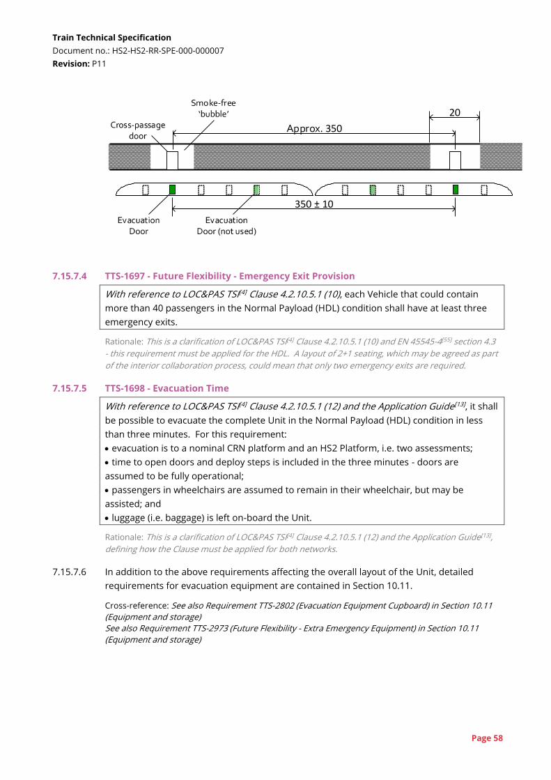
Train Technical Specification
Document no.: HS2-HS2-RR-SPE-000-000007
Revision: P11
Page 58
20
Approx. 350
350 ± 10
7.15.7.4 TTS-1697 - Future Flexibility - Emergency Exit Provision
With reference to LOC&PAS TSI[4] Clause 4.2.10.5.1 (10), each Vehicle that could contain
more than 40 passengers in the Normal Payload (HDL) condition shall have at least three
emergency exits.
Rationale: This is a clarification of LOC&PAS TSI[4] Clause 4.2.10.5.1 (10) and EN 45545-4[55] section 4.3
- this requirement must be applied for the HDL. A layout of 2+1 seating, which may be agreed as part
of the interior collaboration process, could mean that only two emergency exits are required.
7.15.7.5 TTS-1698 - Evacuation Time
With reference to LOC&PAS TSI[4] Clause 4.2.10.5.1 (12) and the Application Guide[13], it shall
be possible to evacuate the complete Unit in the Normal Payload (HDL) condition in less
than three minutes. For this requirement:
evacuation is to a nominal CRN platform and an HS2 Platform, i.e. two assessments;
time to open doors and deploy steps is included in the three minutes - doors are
assumed to be fully operational;
passengers in wheelchairs are assumed to remain in their wheelchair, but may be
assisted; and
luggage (i.e. baggage) is left on-board the Unit.
Rationale: This is a clarification of LOC&PAS TSI[4] Clause 4.2.10.5.1 (12) and the Application Guide[13],
defining how the Clause must be applied for both networks.
7.15.7.6 In addition to the above requirements affecting the overall layout of the Unit, detailed
requirements for evacuation equipment are contained in Section 10.11.
Cross-reference: See also Requirement TTS-2802 (Evacuation Equipment Cupboard) in Section 10.11
(Equipment and storage)
See also Requirement TTS-2973 (Future Flexibility - Extra Emergency Equipment) in Section 10.11
(Equipment and storage)
Train Technical Specification
Document no.: HS2-HS2-RR-SPE-000-000007
Revision: P11
Page 59
7.15.8 Doorway positions
7.15.8.1 TTS-299 - Door Arrangement - Symmetry - Mandatory
The Exterior Doors shall be located in symmetrical positions, either side of both the lateral
and longitudinal centre-lines of the Unit.
Rationale: Adoption of a PEP system is still under consideration. The HS2 Network has a triangular
junction near Birmingham, which will cause Units to be frequently turned around and hence the
orientation of the Unit at a platform cannot be guaranteed. The Exterior Doors must align with the
PEP system regardless of the orientation of the Unit.
7.15.8.2 TTS-1660 - Train Captain's Door Location - Mandatory
It shall be possible to access the Cab from the exterior of the Unit without needing to pass
through a Saloon.
Rationale: This is specified to ensure there is reasonable access to the Cab, either via dedicated cab
doors, or through Exterior Doors positioned close to the rear of the Cab.
7.15.8.3 TTS-2629 - Door Arrangement - Consistency
The position of all Exterior Doors, except the Exterior Doors closest to the Cab, shall be in a
consistent position relative to the end of the vehicle.
Rationale: This will minimise the need for any PEP installation to be customised to a particular rolling
stock design. It is assumed, but not required, that there will be an Exterior Door between the Cab
and first Saloon.
7.16 Internal climate
See also LOC&PAS TSI[4] §4.2.5.8 and §4.2.9.1.7
7.16.1 Saloon climate
7.16.1.1 The requirements of this section are based on EN 13129[32] with some amendments. All
terminology is consistent with and defined in EN 13129.
7.16.1.2 TTS-383 - Heating Performance - Mandatory
The Unit shall be able to maintain the mean interior temperature, Tim, of the Saloon at 21°C
or higher, when:
the external temperature is -6°C;
the Unit is at any speed from stationary to 360km/h;
no solar load;
no Passengers in the Saloon; and
fresh air is provided at a rate that would provide 15m³/h/passenger if there were 30% of
Normal Payload (HDL) in the Saloon.
Rationale: These conditions are developed from EN 13129[32] Section 7.1.1 as it applies to HS2 (Zone I
winter), with an increase in the external temperature to the normal minimum used for the UK.
Train Technical Specification
Document no.: HS2-HS2-RR-SPE-000-000007
Revision: P11
Page 60
7.16.1.3 TTS-384 - Cooling Performance - Mandatory
The Unit shall be able to maintain the mean interior temperature, Tim, of the Saloon at 25°C
or lower, when:
the external temperature is +29°C;
there is 45% RH;
the Unit is at any speed from stationary to 360km/h;
there is 600W/m² equivalent solar load;
the Unit is in Normal Payload (HDL) condition; and
15m³/h/passenger fresh air (as per EN 13129[32] Table 11) is provided.
Rationale: This is the same requirement as EN 13129 Section 7.1.1, except that the external
temperature has been increased by 1K from Zone III summer conditions to account for future climate
change.
7.16.1.4 TTS-1074 - Full Capacity Range
The Passenger HVAC shall continue to operate at full capacity between the following limits:
-15°C Tem, no solar load;
+34°C Tem, 30% RH, 600W/m² equivalent solar load (external operation); and
+43°C Tem, 30% RH, no solar load (tunnel operation)
while the Unit is at any payload up to Exceptional Payload (HDL).
Rationale: This is the same requirement as EN 13129[32] Section 7.1.2, except that the external
temperature has been increased by 1K from Zone III summer conditions to account for future climate
change. In addition, tunnel conditions have also been specified. Payload up to Exceptional Payload
has been added. The Unit may see a payload between Normal and Exceptional in degraded
conditions, and full HVAC capacity must be maintained.
7.16.1.5 TTS-1075 - Reduced Capacity Range
The Passenger HVAC shall continue to operate at reduced capacity up to the following
limits:
+39°C Tem, 25% RH, 600W/m² equivalent solar load (external operation); and
+50°C Tem, 30% RH, no solar load (tunnel operation).
Rationale: This is the same requirement as EN 13129[32] Section 7.1.2, except that the external
temperature has been increased by 1K from Zone III summer conditions to account for future climate
change. In addition, tunnel conditions have also been specified.
7.16.1.6 TTS-1083 - Quality of Saloon HVAC Regulation
The Passenger HVAC shall regulate the mean interior temperature, Tim, of the Saloon to the
target internal temperature, Tic, in accordance with EN 13129[32] Section 9.3.
Rationale: Implementation of EN 13129 Section 9.3.
Cross-reference: See also Requirement TTS-385 (Temperature Regulation) in Section 9.20.1 (HVAC
control)

Train Technical Specification
Document no.: HS2-HS2-RR-SPE-000-000007
Revision: P11
Page 61
7.16.1.7 TTS-1084 - Comfort Conditions
Comfort conditions defined in EN 13129[32] Sections 10.1.1 to 10.1.4, inclusive, shall be
complied with at all locations within the Saloon. For the purposes of this requirement, the
normal range and extended range of q1,q2 shall be:
Winter, normal: Tem ≥ 0°C;
Winter, extended: -6°C ≤ Tem < 0°C;
Summer, normal: Tem ≤ +23°C; and
Summer, extended: +23°C < Tem ≤ +29°C.
Rationale: This is modified from EN 13129 by a 1K increase in summer temperatures to account for
climate change and a 4K increase in minimum temperature to account for normal UK minimum
temperature.
7.16.1.8 TTS-1066 - Conformity Level
The overall conformity level with TTS-1083 and TTS-1084, calculated in accordance EN
13129[32] Section 4 and Annex B, shall be Level A or B (i.e. ≥ 93%).
Rationale: The overall conformity level is a measure of how well the HVAC system provides a
comfortable environment for passengers. The methodology is defined in EN 13129.
7.16.1.9 TTS-1085 - Fresh Air
For payloads up to Normal Payload (HDL), the Passenger HVAC shall be able to supply at
least the fresh air levels in accordance with EN 13129[32] Table 11.
Rationale: Implementation of EN 13129 Clause 10.1.5.1
Cross-reference: See also Requirement TTS-1087 (Fresh Air Regulation) in Section 9.20.1 (HVAC
control)
7.16.1.10 TTS-2463 - CO2 Level - Across Route
With reference to LOC&PAS TSI[4] Clause 4.2.5.8 (2), the Passenger HVAC shall be able to
maintain the CO2 level in the Saloon and the Vestibule below 1600 ppm, while the Unit is
operating a Service from Birmingham Curzon Street to London Euston and return. This
shall be achieved using the parameters specified in Appendix T.
Rationale: This reduces the CO2 concentration compared to the LOC&PAS TSI and gives a more
applicable assessment. The HS2 Network will have long tunnels where provision of fresh air will be
more difficult due to pressure sealing limitations, including multiple trains in tunnels - see TTS-146.
The HVAC must control the fresh air over the journey, potentially supplying more fresh air outside of
the tunnels, to ensure this requirement is achieved. The 1600ppm level is specified as a good quality
environment, based on the level specified in draft versions of EN 14750 for a Category A vehicle. The
external CO2 concentration is taken from EN 13129[32], section 10.1.5.
7.16.1.11 Two different requirements are specified for emergency ventilation. In the majority of
environmental conditions, TTS-388 would apply. In high temperature conditions it is
necessary to provide increased air flow to manage heat and humidity in the stalled Unit.
This would be achieved in combination with opening Exterior Doors and Interior Doors
(TTS-3477), if necessary, and switching to an emergency ventilation mode.
Train Technical Specification
Document no.: HS2-HS2-RR-SPE-000-000007
Revision: P11
Page 62
Cross-reference: See also Requirement TTS-3270 (Emergency High Ventilation Mode) in Section 9.20.1
(HVAC control)
7.16.1.12 TTS-388 - CO2 Level - Emergency
With reference to LOC&PAS TSI[4] Clause 4.2.5.8 (2), following a loss of the 25kV power
supply, the Passenger HVAC shall maintain the CO2 levels below 10,000 ppm for 60
minutes, assuming fresh air can be drawn into the Unit at a CO2 concentration, Cext, of 400
ppm. The Unit shall be in Exceptional Payload (HDL) condition.
Rationale: This extends the duration specified in the LOC&PAS TSI from 30 minutes to 60 minutes
Cross-reference: See also Requirement TTS-3248 (60-Minute Auxiliary Supply) in Section 7.7 (Auxiliary
Power Supply)
7.16.1.13 TTS-3269 - Fresh Air Flow - Emergency
Following a loss of the 25kV power supply, the Passenger HVAC shall provide
5m³/h/Passenger of fresh air for 60 minutes. The Unit shall be in Normal Payload (HDL)
condition. Interior Doors may be held open and Exterior Doors may be open with barriers
in place or other similar measures may be taken to improve air-flow.
Rationale: In high temperatures, it is predicted that the fresh air flow necessary to maintain 10 000
ppm CO2 will be too low to manage heat-related illness in Passengers. A higher rate of fresh air is
required to reduce humidity. Since the Unit will be stalled measures such as opening Exterior Doors
slightly can be used to maximise the air flow.
Cross-reference: See also Requirement TTS-3337 (Door Barrier) in Section 10.11 (Equipment and
storage)
See also Requirement TTS-3477 (Open All Interior Doors) in Section 9.34 (Interior Doors)
7.16.1.14 TTS-1094 - Vestibule Temperature Regulation
The temperature Tim in each Vestibule shall be regulated with respect to the Tic for that
Vehicle in accordance with EN 13129[32] Table 13 (row 2).
Rationale: Implementation of EN 13129 Clause 10.2
7.16.1.15 TTS-2059 - Draughts through Vestibule
The Passenger HVAC shall minimise drafts in the Saloon when the Exterior Doors and
Interior Doors are both open and there is a significant difference in temperature between
interior and exterior.
Rationale: To assist with dwell times, automatic opening of vestibule doors is specified, but this
creates the risk of draughts through the saloon.
Cross-reference: See also Requirement TTS-1813 (Automatic Interior Door Opening - Stations) in
Section 9.34 (Interior Doors)
7.16.1.16 TTS-1080 - Door Opening Sequence
During three sequences of
one minute with Exterior Doors and Interior Doors open; and
19 minutes with all doors closed,
Train Technical Specification
Document no.: HS2-HS2-RR-SPE-000-000007
Revision: P11
Page 63
the range of mean interior temperature, Tim, of the Saloon, with respect to Tic, shall be
within the q2 limit defined in EN 13129[32] Clause 10.1.1.
Rationale: Implementation of EN 13129 Clause 8.6, using the cycle proposed in the EN.
7.16.1.17 TTS-1096 - Toilet Temperature Regulation
The mean interior temperature, Tim, in each Toilet shall be regulated with respect to the Tic
for that Vehicle in accordance with EN 13129[32] Table 13 (row 3).
Rationale: Implementation of EN 13129 Clause 10.2
7.16.1.18 TTS-1098 - Catering Temperature Regulation
The mean interior temperature, Tim, of Catering Areas shall be regulated with respect to the
Tic for that Vehicle in accordance with EN 13129[32] Table 14.
Rationale: Implementation of EN 13129 Clause 10.3
Cross-reference: See also Section 10.8 (Catering)
7.16.1.19 TTS-1099 - Temperature Limits
Surface temperatures and air flows in the Saloon shall comply with EN 13129[32] Table 15.
For the purposes of this requirement, the normal range and extended range shall be:
Winter, normal: Tem ≥ 0°C
Winter, extended: -6°C ≤ Tem < 0°C
Summer, normal: Tem ≤ +23°C
Summer, extended: +23°C < Tem ≤ +29°C
Rationale: This is modified from EN 13129 by a 1K increase in summer temperatures to account for
climate change and a 4K increase in minimum temperature to account for normal UK minimum
temperature.
7.16.1.20 TTS-1428 - Manage Smells
The Passenger HVAC shall minimise the spread of smells from the Toilets and Catering
Area into the Saloon and Vestibule.
Rationale: Managing smells, particularly around Toilets adjacent to Vestibules is important to
passengers' perception of the Vehicle.
7.16.1.21 TTS-1125 - Future Flexibility - HVAC Performance 1
The Passenger HVAC shall enable all performance requirements to be met following
addition or removal of a Full-width Partition at the halfway point in the Saloon, if the Saloon
is longer than 12m.
7.16.1.22 TTS-3512 - Future Flexibility - HVAC Performance 2
The Passenger HVAC shall enable all performance requirements to be met following
addition or removal of:
a Toilet; and
a Catering Area.
Train Technical Specification
Document no.: HS2-HS2-RR-SPE-000-000007
Revision: P11
Page 64
Rationale: It must be possible to make changes to the interior with minimal impact on the HVAC
system.
7.16.2 Cab climate
7.16.2.1 The requirements of this section are based on EN 14813[41] with some amendments. All
terminology is consistent with EN 14813.
7.16.2.2 TTS-1128 - Heating Performance
The Unit shall be able to maintain the mean interior temperature, Tim, of the Cab at 18°C or
above, when:
the external temperature is -10°C;
the Unit is at any speed from stationary to 360km/h;
there is no solar load;
the Cab is empty; and
fresh air is provided at 50% of its maximum operational rate.
Rationale: Implementation of EN 14813[41] Clause 7.1
7.16.2.3 TTS-1129 - Cooling Performance (External)
The Unit shall be able to maintain the mean interior temperature, Tim, of the Cab at 22°C or
below, when:
the external temperature is +29°C;
there is 45% RH;
the Unit is stationary;
the Cab is occupied by two people;
there is 600W/m² equivalent solar load; and
60m³/h fresh air is provided to the Cab.
Rationale: This is derived from EN 14813[41] Clause 7.3 for a Category A train with fresh air for two
people (Train Captain and an instructor) and an increase of 1K to account for climate change.
7.16.2.4 TTS-1284 - Full Capacity Range
The Cab HVAC shall continue to operate at full capacity between the following limits:
-15°C Tem, no solar load;
+34°C Tem, 30% RH, 600W/m² equivalent solar load (external operation); and
+43°C Tem, 30% RH, no solar load (tunnel operation).
Rationale: Implementation of EN 14813[41] Clause 6.3
7.16.2.5 TTS-1285 - Reduced Capacity Range
The Cab HVAC shall continue to operate at reduced capacity up to the following limits:
+39°C Tem, 25% RH, 600W/m² equivalent solar load (external operation); and
+50°C Tem, 30% RH, no solar load (tunnel operation).
Rationale: Implementation of EN 14813[41] Clause 6.3
7.16.2.6 There are no requirements for pre-heat / pre-cool times. In normal service, it is expected
that pre-heating and pre-cooling will be triggered automatically.
Train Technical Specification
Document no.: HS2-HS2-RR-SPE-000-000007
Revision: P11
Page 65
Cross-reference: See also Requirement TTS-1313 (Automatic Pre-heat / Pre-cool) in Section 9.20.1
(HVAC control)
7.16.2.7 TTS-1139 - Cab Comfort Parameters
The comfort parameters of EN 14813[41] Sections 9.1 to 9.5 inclusive shall be complied with
for a Category A Vehicle.
Rationale: Implementation of EN 14813.
Cross-reference: See also Requirement TTS-1138 (Cab Temperature Control) in Section 9.20.1 (HVAC
control)
7.16.2.8 TTS-1143 - Cab Fresh Air Flow
The Cab HVAC shall be capable of supplying 60m³/h fresh air to the Cab:
in Normal Operation; and
following a loss of the main 25kV power supply (see TTS-3248).
Rationale: This provides sufficient fresh air for two people in the cab, based on the minimum
quantities specified in EN 14813[41].
Cross-reference: See also Requirement TTS-1144 (Cab Fresh Air Regulation) in Section 9.20.1 (HVAC
control)
See also Requirement TTS-3248 (60-Minute Auxiliary Supply) in Section 7.7 (Auxiliary Power Supply)
7.16.3 Air filtration
7.16.3.1 TTS-1681 - Air Filtration
The Cab HVAC and Passenger HVAC shall filter untreated air to a level at least equivalent to
grade G4 in accordance with EN 779[29].
Rationale: This is the filtration level recommended in EN 13129[32]. While EN 779 has been replaced
by EN ISO 16890-1[73], there is no clear consensus on the equivalent measure.
7.17 Heat output
7.17.1 Both Euston and Old Oak Common stations are planned to be relatively enclosed. Heat
emissions from the Units could cause excessive temperatures inside the station
environments at these locations. The following requirements and the requirements of
Section 9.21 of this TTS are specified to manage heat output from the Unit. It is anticipated
that some flexibility will be required with settings to enable systems to be adjusted to
manage the heat from the Units.
7.17.2 TTS-914 - Heat Release - OOC Station (PQTS-449)
During the dwell at Old Oak Common station, the rate of heat release from the Unit shall
not exceed 700kW, averaged over a two-minute dwell, assuming an external temperature
of 35°C. The Unit is assumed to be in Normal Payload (1SL) condition. Exterior Doors are
assumed to be open for 90 seconds of the dwell. The humidity ratio shall be 0.012
kgwater/kgdry_air. The Unit may switch to a Limited Heat Release State to achieve this
requirement.
Train Technical Specification
Document no.: HS2-HS2-RR-SPE-000-000007
Revision: P11
Page 66
Rationale: HS2 interface - Old Oak Common station has restrictions on its ventilation. It is
considered that the Unit will have to adopt specific settings while at the station to limit heat output
(e.g. reducing traction cooling).
7.17.3 TTS-915 - Heat Release - Euston Station (PQTS-458)
During the dwell at Euston station, the rate of heat release from the Unit shall not exceed
350kW, averaged over a 28-minute dwell (described below), assuming an external
temperature of 35°C. The Unit is assumed to be in Normal Payload (1SL) condition.
Exterior Doors are assumed to be open for 2 minutes at the start of the dwell and 10
minutes at the end of the dwell. The Unit shall be in a Standby State from 2 minutes to 18
minutes of the dwell with no Passengers on-board. The humidity ratio shall be 0.012
kgwater/kgdry_air. The Unit may switch to a Limited Heat Release State to achieve this
requirement.
Rationale: HS2 interface - Euston station has restrictions on its ventilation, and hence heat output
must be limited.
Cross-reference: See also Section 9.21 (Heat management)
7.17.4 TTS-1317 - Heat Release Evenness
When stationary during a station dwell as specified in TTS-914 and TTS-915, the Unit shall
emit heat evenly along the Unit such that no Vehicle emits more than 25% of the total heat
output, averaged over the length of the dwell.
Rationale: HS2 interface - The design of the station ventilation systems is being based on an even
heat output along the Unit.
7.18 Acoustics
See also NOI TSI[7] and GM/RT2160[89]
7.18.1 External noise
7.18.1.1 TTS-178 - Pass-by Noise (PQTS-186)
The limit value for the A-weighted equivalent continuous sound pressure level at a speed of
360km/h (LpAeq,Tp,(360km/h)) measured in accordance with EN ISO 3095[71] on a track at the
limits defined in EN ISO 3095 Section 6.2, 3.5m above rail level, 25m from the track shall be
[●] dB.
Rationale: This requirement extends the NOI TSI evaluation of pass-by noise to 360km/h, and also
changes the measurement position to 25m from the track. 25m has been the basis for analysis
carried out to date. The requirement is specified in accordance with conditions in EN ISO 3095 so
that it is assessable. It cannot be assumed that the track quality will exceed the EN ISO 3095 limits.
These conditions will not be completely reproducible on the HS2 Network (e.g. HS2 Network will have
slab track). The TMM's V&V plan will need to propose suitable V&V activities to address this.
7.18.1.2 Update for contract - The missing value in requirement TTS-178 will be populated in the
contracted version of the TTS using the value provided in the Stage 5 Tender Evaluation.

Train Technical Specification
Document no.: HS2-HS2-RR-SPE-000-000007
Revision: P11
Page 67
7.18.1.3 TTS-3201 - Pass-by Noise 200km/h
The limit value for the A-weighted equivalent continuous sound pressure level measured at
a speed of 200km/h in accordance with EN ISO 3095[71], 1.2m above rail level, 7.5m from
the track and normalised to 80km/h in accordance with formula (1) of the NOI TSI[7]
(LpAeq,Tp,(80km/h)) shall be 80dB.
Rationale: To ensure there is no negative impact on operation on the CRN, compared to existing
rolling stock, the Unit needs to meet the NOI TSI for a maximum operational speed of 200km/h.
7.18.1.4 TTS-181 - High-level Noise (PQTS-250)
The external pass-by noise of the pantograph and upper body aerodynamics shall be
minimised.
Rationale: Noise barriers on the infrastructure can be provided to mitigate low-level noise
(particularly wheel-rail noise), and therefore aerodynamic noise from the roof and pantographs will
become a more dominant noise source. Managing high level noise is important for achieving the HS2
Environmental Minimum Requirements.
7.18.1.5 TTS-861 - Stationary Noise - Depot
At any measurement position required to demonstrate compliance to NOI TSI[7] Clause
4.2.1 the limit for the maximum AF-weighted sound pressure level (LipAFmax), at any time that
the Unit
is stationary; and
is being maintained, stabled or prepared for service;
but excluding sounding of the horn or depot warning device,
shall be 85dB.
Rationale: Loud noises from trains in depots can be particularly annoying for neighbours of the
depot. The NOI TSI[7] specifies a requirement for the air dryer exhaust valve, however, all other
equipment should also not exceed this limit.
7.18.2 Internal noise - Saloon and Vestibule
7.18.2.1 TTS-183 - Open Air Saloon Max Noise Level (PQTS-192)
The A-weighted equivalent continuous sound pressure level (LpAeq,20s) at any point within
the Saloon, measured in accordance with EN ISO 3381[72] and Appendix P, while the Unit is
operating in the open, at 360km/h on reference track as defined in EN ISO 3095[71], shall
not exceed:
Preferred 1: The open air saloon maximum noise level shall not exceed 73dB(A).
Preferred 2: The open air saloon maximum noise level shall not exceed 74dB(A).
Preferred 3: The open air saloon maximum noise level shall not exceed 75dB(A).
Preferred 4: The open air saloon maximum noise level shall not exceed 76dB(A).
Rationale: The maximum saloon noise level is specified to account for noise at locations such as
above running gear and beneath the pantograph, if these occur in the Saloon.
Train Technical Specification
Document no.: HS2-HS2-RR-SPE-000-000007
Revision: P11
Page 68
7.18.2.2 TTS-3237 - Open Air Saloon Average Noise Level
The average A-weighted equivalent continuous sound pressure level (LpAeq,20s) between all
Saloons, measured in accordance with EN ISO 3381[72] and Appendix P, while the Unit is
operating in the open, at 360km/h on reference track as defined in EN ISO 3095[71], shall
not exceed:
Preferred 1: The open air saloon average noise level shall not exceed 69dB(A).
Preferred 2: The open air saloon average noise level shall not exceed 70dB(A).
Preferred 3: The open air saloon average noise level shall not exceed 71dB(A).
Preferred 4: The open air saloon average noise level shall not exceed 72dB(A).
Rationale: The average saloon noise level provides a target for the quietest part of the Saloons, but
considering all Vehicles.
7.18.2.3 TTS-184 - Tunnel Saloon Noise Level (PQTS-420)
The A-weighted equivalent continuous sound pressure level (LpAeq,20s), measured in
accordance with EN ISO 3381[72], at any point within the Saloon, measured while the Unit is
operating in the Northolt Tunnel, as defined in Appendix P, at 320 km/h, shall not exceed:
Preferred 1: The tunnel saloon noise level shall not exceed 76dB(A).
Preferred 2: The tunnel saloon noise level shall not exceed 77dB(A).
Preferred 3: The tunnel saloon noise level shall not exceed 78dB(A).
Preferred 4: The tunnel saloon noise level shall not exceed 79dB(A).
Rationale: A high proportion of the HS2 network is in tunnel or cutting or behind a noise barrier or
parapet. Therefore, internal noise levels in these locations will have a significant impact on
Passengers' perception of the journey.
7.18.2.4 For the purposes of TTS-184, Northolt Tunnel shall be as defined in Appendix P, section
P.3.3.
7.18.2.5 TTS-1344 - Saloon Noise (Stationary)
The A-weighted equivalent continuous sound pressure level (LpAeq,20s), measured in
accordance with EN ISO 3381[72], at any point within the Saloon shall not exceed 62dB(A),
while the Unit is stationary, with all systems running.
7.18.2.6 TTS-1350 - Vestibule Noise
The A-weighted equivalent continuous sound pressure level (LpAeq,20s), measured in
accordance with EN ISO 3381[72], at any point within the Vestibule shall not exceed 80dB(A),
while the Unit is operating at 360km/h in the open on reference track as defined in ISO
3095[71].
Train Technical Specification
Document no.: HS2-HS2-RR-SPE-000-000007
Revision: P11
Page 69
7.18.3 Internal noise - Cab
7.18.3.1 TTS-865 - Cab Interior Noise - Open Track
With reference to NOI TSI[7] Section 4.2.4, the A-weighted equivalent continuous sound
pressure level (LpAeq,20s), measured in accordance with EN 15892[47], in the Cab shall not
exceed the 76 dB(A), while the Unit is operating on reference track as defined in EN ISO
3095[71] at 360km/h.
Rationale: This requirement is more onerous than the NOI TSI to account for the high proportion of
high speed running and tunnel operation on the HS2 Network.
7.18.3.2 TTS-866 - Cab Interior Noise - Tunnels
The A-weighted equivalent continuous sound pressure level (LpAeq,20s), measured in
accordance with EN ISO 3381[72], in the Cab shall not exceed 80 dB(A), while the Unit is
operating in the Northolt Tunnel, as defined in Appendix P, at 320km/h.
Rationale: This covers noise emissions in the two long tunnels at the southern end of the HS2
Network.
7.18.3.3 TTS-1169 - Cab Interior Noise - Stationary
The A-weighted equivalent continuous sound pressure level (LpAeq,20s), measured in
accordance with EN ISO 3381[72], in the Cab shall not exceed 62 dB(A), while the Unit is
stationary with all systems operating, except external warning devices.
Rationale: This requirement is specified to manage the noise of in-cab HVAC systems.
7.18.3.4 TTS-1346 - Detonator Audibility
With reference to Clause 2.1.1 of GM/RT2160[89], the Train Captain shall be made aware
when the Unit runs over a detonator at any speed up to 140mph.
Rationale: Audibility of detonators is only required on the CRN. It is recognised that reducing noise
levels in the Cab may mean it is not possible to adequately hear detonators in the Cab. The
Purchaser would support a deviation (raised in accordance with the Railway Group Standards
Code[77]) to adopt an alternative solution to inform the Train Captain.
7.18.4 General noise requirements
7.18.4.1 TTS-1354 - Annoying Noise Features
The Unit shall minimise bangs, rattles, squeaks, pure tones, whistling, scraping or grating
sounds that could cause annoyance or alarm to passengers, Train Captain and Crew, and
neighbours of the railway.
Rationale: There are numerous features of existing rolling stock that should be avoided such as:
- loud circuit breakers
- Exterior Doors that make a grating sound when they open
- Persistent mechanical noise from HVAC units
- rattling and vibrating interior panels
- tonal noise from open jacking points
Train Technical Specification
Document no.: HS2-HS2-RR-SPE-000-000007
Revision: P11
Page 70
7.18.4.2 TTS-1967 - Pure Tones
The noise limits specified in sections 7.18.1, 7.18.2 and 7.18.3 shall be reduced by 3dB(A) if
significant pure tones in the ‘one-third octave’ bands centred on 100 Hz - 10 kHz, are
present. The significance of pure tone noise in this context shall be assessed using the
‘one-third octave’ method in Annex K of ISO 1996-2[70A]. The 'possible choice' values
presented in Annex K of ISO 1996-2 for identifying the presence of prominent tones shall
be adopted.
Rationale: Pure tone elements (e.g. whistles and hums) within a sound spectrum can be particularly
noticeable and annoying, even when they do not necessarily contribute significantly to the overall A-
weighted level.
7.18.5 Communication audibility
7.18.5.1 TTS-871 - STI PA Level
The spoken information shall have a minimum STI-PA level of
0.58 in Saloon, including all Seating Positions; and
0.45 in Vestibules and Toilets;
in accordance with EN 60268-16[67] while the Unit is travelling on both open track (as per
TTS-183) and in a tunnel (as per TTS-184).
Rationale: A higher value of STI-PA has been required compared to the PRM TSI[6], based on the
quality of service that should be delivered.
Cross-reference: See also Requirement TTS-1405 (Volume Adjustment) in Section 9.25.2 (Audio
information)
7.19 Operational environment
See also LOC&PAS TSI[4] §4.2.6.1
7.19.0 It is recognised that it is difficult to specify requirements for operational environment
which can be validated and to test every scenario specified. The requirements of this
section define the scope of operational environment interfaces. It is expected that these
requirements will be demonstrated through reference to particular design features that
address each requirement. The TMM will need to propose appropriate V&V activities and
reference existing design precedents to show the robustness of these designs.
7.19.1 Temperature and altitude
7.19.1.1 TTS-186 - Climate Zone Definitions (PQTS-94)
With reference to LOC&PAS TSI[4] Section 4.2.6.1.1 and EN 50125[61], the climatic zone T1
shall apply.
Rationale: This is the zone applicable to the UK.
7.19.1.2 TTS-189 - Tunnel Environment - Summer (PQTS-112)
The Unit shall be capable of Normal Operation in the tunnels that will transition from 25°C
at the tunnel entry portal to 35°C within the tunnel. Tunnel relative humidity will vary
between 30% and 50% during summer.
Train Technical Specification
Document no.: HS2-HS2-RR-SPE-000-000007
Revision: P11
Page 71
Rationale: These are the estimated temperatures in normal summer conditions.
7.19.1.3 TTS-190 - Tunnel Environment - Winter (PQTS-135)
The Unit shall be capable of Normal Operation in the tunnels that will transition from -6°C
at the tunnel entry portal to 30°C within the tunnel. Tunnel relative humidity will vary
between 90% at the cool end of the tunnel and 20% to 30% at the warmest part of the
tunnel.
Rationale: These are the estimated conditions in normal winter conditions.
7.19.1.4 TTS-191 - Tunnel Congestion Conditions - Average (PQTS-136)
The Unit shall be capable of Normal Operation when the tunnel temperature is an average
of 43°C, with variations around the vehicle and a humidity ratio of 0.012 kgwater/kgdry_air.
Rationale: HS2 interface - This is the estimated temperature in the tunnel during operational
congestion when trains stop in the tunnel and air flow through the tunnel is reduced. The
temperature around the Unit will depend on the Unit's heat release characteristics.
7.19.1.5 TTS-192 - Tunnel Congestion Conditions - Maximum (PQTS-137)
The Unit shall be capable of Normal Operation when the tunnel temperature is an average
of 50°C, with variations around the Vehicle, and a humidity ratio of 0.012 kgwater/kgdry_air for
up to five minutes.
Rationale: HS2 interface - This temperature is predicted during the initial stages of operational
congestion in tunnels. In these circumstances, the tunnel ventilation system may be required to
reverse the prevailing airflow direction and the average temperature in the tunnel is predicted to rise
to 50°C.
7.19.1.6 Note that Normal Operation is defined as full performance, including full performance of
traction systems (see Section 2). The temperature of 15°C specified in requirements in
Section 7.1 and 7.2 is only specified to enable consistent, comparable simulations.
7.19.2 Precipitation and fluids
7.19.2.1 TTS-187 - Maximum Snow and Flood Water Levels (PQTS-386)
The Unit shall be capable of Normal Operation when:
snow is up to 200mm above the rail level; and
flood water is up to 50mm below the rail level,
subject to operational limitations in the Rule Book[104] and similar limitations in any rule
book agreed for the HS2 Network.
Rationale: The UK Rule Book specifies these as the limits of normal operation. The limit of flood
water is the bottom of the rail head, which is approximately 50mm below rail level. The same rule
will be applied to the HS2 Network.
7.19.2.2 TTS-340 - Ice and Snow
The Unit shall be capable of Normal Operation under all snow and ice conditions that the
Unit may encounter in service, subject to operational limitations in the Rule Book[104] and
similar limitations in any rule book agreed for the HS2 Network.
Train Technical Specification
Document no.: HS2-HS2-RR-SPE-000-000007
Revision: P11
Page 72
Rationale: Particular types of snow have caused issues for previous rolling stock in the UK. In
particular, dry, powdery snow has caused issues with traction systems, and this was then made
worse by travelling into tunnels.
7.19.2.3 TTS-2181 - Ice Build-up
The Unit shall be resistant to the build-up of snow and ice, and subsequent detachment of
large blocks of ice.
Rationale: Trains on High Speed 1 have suffered damage in cold weather when ice formed around
the bogie and bolster, and then detached when the mass was too large or the train entered warmer
tunnels. The detached ice caused significant damage to underframe equipment and could cause
damage to lineside equipment.
7.19.2.4 TTS-1749 - Protect Passengers and Staff
The Unit shall protect Passengers, the Train Captain and Train Crew and interior
furnishings from all fluids that the Unit will encounter in service, including precipitation and
traversing a wash plant.
7.19.2.5 TTS-337 - Fluids and Chemical Resistance
The Unit shall be resistant to degradation from all fluids and chemicals that the Unit will
encounter in service.
Cross-reference: See also Requirement TTS-886 (Use of Cleaning Chemicals) in Section 7.23.2
(Cleanability)
7.19.2.6 TTS-2830 - Precipitation Level
The Unit shall be capable of Normal Operation with precipitation of up to 60mm/h
including hail, sleet, and snow.
7.19.3 Other elements of the operational environment
7.19.3.1 TTS-188 - Dust and Particles (PQTS-111)
The Unit shall be resistant to all dust and particles that the Unit may encounter in service.
Rationale: In addition to normal levels of dust the Units will be exposed to higher levels of dust,
including concrete, associated with construction following opening of each phase, particularly in the
tunnels.
7.19.3.2 TTS-2874 - Accumulation of Debris
The Unit shall prevent leaves, litter and other debris accumulating within the Vehicle roof,
underframe or other areas where they could affect operation of the Unit or become a fire
risk.
Rationale: Leaves may get sucked into parts of the underframe or may fall onto the roof when the
Unit is stabled. These should not be able to cause blockages or accumulate such that they become a
fire risk.
Train Technical Specification
Document no.: HS2-HS2-RR-SPE-000-000007
Revision: P11
Page 73
7.20 Environmental impact
7.20.1 TTS-847 - Greenhouse Gas Emissions during Lifecycle
The total life-cycle (upstream, core and downstream) global warming potential impact of
the Unit, measured in kg CO2 equivalent per passenger km, calculated in accordance with
EN ISO 14025[74], the Product Category Rules for Rolling Stock[112] and Appendix J, shall be:
Preferred 1: The life-cycle global warming impact shall be no more than 0.00186 kg CO2 eq
/ passenger km.
Preferred 2: The life-cycle global warming impact shall be no more than 0.00220 kg CO2 eq
/ passenger km.
Rationale: The requirement is consistent with requirements for the High Speed 2 Project to minimise
carbon emissions and supports the strategic goal to design, construct and operate the railway to
reduce carbon.
7.20.2 TTS-2195 - Recyclability
The recyclability of the Unit, calculated using UNIFE Recyclability and Recoverability
Calculation Method Railway Rolling Stock[113], shall be:
Preferred 1: The recyclability shall be at least 95%.
Preferred 2: The recyclability shall be at least 90%.
Rationale: This is specified to align with goal of adoption of circular economy principles.
7.20.3 TTS-2192 - Recoverability
The recoverability of the Unit, calculated using UNIFE Recyclability and Recoverability
Calculation Method Railway Rolling Stock[113], shall be:
Preferred 1: The recoverability shall be at least 97%.
Preferred 2: The recoverability shall be at least 95%.
Rationale: This is specified to align with goal of adoption of circular economy principles.
7.20.4 TTS-2199 - Contaminants
The Unit shall prevent any potentially contaminative fluids from being released from the
Unit into the environment. Any non-contaminative fluids may be released, so long as the
necessary contents or approvals in accordance with HS2 Ltd's Water Resources and Flood
Risk Consents Standard[123] have been obtained.
Rationale: Compliance with HS2 Ltd's standard is necessary to support HS2 Ltd's legal requirements.
The TMM will need to provide information about any fluids that can be released to support any
consents or approvals that may be necessary. Release of water from bio-reactor toilets will need to
be in controlled locations to prevent it entering the wider environment.
Cross-reference: See also Requirement TTS-2641 (Discharge Water Release) in Section 9.32 (Toilets
and Sanitary Systems)
7.21 Fire
See also LOC&PAS TSI[4] §4.2.10 and GM/RT2130[85]
Cross-reference: See also Section 9.22 (Fire and smoke detection)
Train Technical Specification
Document no.: HS2-HS2-RR-SPE-000-000007
Revision: P11
Page 74
See also Section 10.21 (Fire extinguishers)
See also Requirement TTS-3480 (Passenger Seat Fire Performance) in Section 10.3.1 (General seat
design)
7.21.1 TTS-197 - Fire Categorisation (PQTS-146)
With reference to LOC&PAS TSI[4] Section 4.2.10, the Unit shall be assessed as Category B.
With reference to EN 45545[53] [54] [55] [56] the Unit shall be assessed as:
Operation Category 3; and
Design Category N.
Rationale: The HS2 Network contains long tunnels that considerably exceed the 5km limit for
Category A rolling stock, and do not have intermediate rescue stations. Although the Unit must have
ATO capability, there is no intention to operate without any staff (Design Category A).
7.21.2 TTS-320 - Running Capability
Following the outbreak of a 'Type 2' fire on-board the Train, as the Train enters any tunnel
on the HS2 Network, at any speed, the Train shall maintain at least the following functions
until the Unit has exited the far end of that tunnel:
braking control;
traction control;
traction power sufficient to maintain a minimum speed of 80km/h;
public address and communication to the Wayside via the GSM-R voice radio;
PEAs and call-for-aids;
ventilation and control of fresh air intake / recirculation;
external and internal door control and power;
ATO / ETCS; and
emergency lighting.
The maintenance of these functions shall be assessed in accordance with EN 50553[65].
Refer to the Data Book[116] for tunnel lengths, gradients and cross-sections.
Rationale: HS2 interface - This requirement is in addition to the LOC&PAS TSI[4] section 4.2.10.4.4.
Rather than specify simply a time-based duration, the Train must be able to get to a place of safety
considering the distance and route profile along the network and impacts on traction of the fire. In
addition to braking and traction, specified in the TSI, additional functions are specified. Note that this
is not to say that other functions should be de-activated in this scenario.
7.21.3 TTS-3249 - Maintain Communications
Public address and internal voice communications between Train Crew and the Train
Captain shall be protected from fire by:
providing redundant connections between components; and
protecting cabling that provides basic voice communications and any necessary power
supply in accordance with PH60 classification when tested in accordance with EN 50200[61A]
or equivalent.
Rationale: If a Train stops in a tunnel with a significant fire, and it is then chosen to evacuate the
Train, it must be possible to maintain communications throughout the Train. It is predicted that the
evacuation process could take up to 60 minutes. It is only necessary to maintain basic
communications functions.
Train Technical Specification
Document no.: HS2-HS2-RR-SPE-000-000007
Revision: P11
Page 75
7.21.4 TTS-1311 - Fire Barriers - General
Fire barriers shall be provided in accordance with EN 45545-3[54], except that the
longitudinal position of the barrier between adjacent passenger areas (Table 1, point 5)
shall be as per TTS-321.
Rationale: EN 45545-3 specifies a maximum spacing of 30m for barriers in passenger areas, which is
considered too far apart considering the likely length of Vehicles and the evacuation scenarios.
7.21.5 TTS-321 - Cross-section Fire Barriers
With reference to LOC&PAS TSI[4] Section 4.2.10.3.4, the Unit shall have a full cross-section
partition fire barrier at each end of each Vehicle, either:
between a vestibule that is at the end of the Vehicle and the Saloon, or
adjacent to the Gangway, provided that TTS-900 and TTS-2078 are adequately complied
with.
The fire barrier shall meet EN 45545-3[54] for a barrier between adjacent passenger areas
(Table 1, point 5).
Rationale: HS2 interface - A more onerous requirement than the LOC&PAS TSI[4] is specified to
permit passengers to be evacuated to adjacent Vehicles in the event of a fire. It must be possible for
a passenger in a wheelchair to be moved to a place of safety beyond a fire barrier. Therefore, if there
is no barrier between the Saloon and Vestibule, it must be possible to evacuate passengers to and
adjacent vehicle, which requires the wheelchair to pass through the gangway (TTS-900, TTS-2078).
The development and adoption of alternative non-physical fire containment and control systems in
place of a fire barrier is not supported.
Cross-reference: See also Requirement TTS-900 (Inter-Vehicle Gangway Clearway - Minimum) in
Section 10.12 (Gangway)
See also Requirement TTS-2078 (Inter-Vehicle Gangway Clearway - Maximisation) in Section 10.12
(Gangway)
7.21.6 TTS-1297 - Peak Heat Release
The Unit design shall ensure that for all reasonably foreseeable fire scenarios, the peak
heat release rate does not exceed 7MW from ignition of the fire. Scenarios shall include a
passenger luggage fire source represented by ignition model 5 defined in EN 45545-1[52B],
Annex A.
Rationale: HS2 interface - A 7MW peak heat release rate has been used in the fire strategy for the
tunnels. An ignition model 5 is specified as this is considered representative of a luggage fire or an
arson attack.
7.22 Reliability
7.22.1 There is an HS2 Sponsor's Requirement for an overall railway reliability of a moving annual
average delay per HS2 service on the HS2 Network of no greater than 30 seconds at an HS2
station destination or the HS2 Network/CRN boundary. To support this, requirements for
mean distance between Service Affecting Failure have been specified in the in the TSA as
part of the Performance Regime (TSA Schedule 5).
Train Technical Specification
Document no.: HS2-HS2-RR-SPE-000-000007
Revision: P11
Page 76
7.22.2 These requirements are included in the TTS in a slightly different form such that the
reliability of the design of the Unit (the "Design") is considered through design and up to
Acceptance.
7.22.3 TTS-200 - MDBSAF (HS2) (PQTS-195)
The Design shall be capable of achieving a mean distance between Service Affecting
Failures of at least 300,000 km while operating on the HS2 Network. Train operation
parameters in Appendix A shall be used for assessment of this requirement.
7.22.4 TTS-3282 - MDBSAF (CRN)
The Design shall be capable of achieving a mean distance between Service Affecting
Failures of at least 160,000 km while operating on the CRN. Train operation parameters in
Appendix A shall be used for assessment of this requirement.
7.22.5 In addition to the requirements for mean distance between Service Affecting Failure, the
following requirements are specified for no single point failure.
7.22.6 TTS-2638 - NSPF Causes Train Immobilisation
No credible single point failure of the Unit's traction, power supply, braking or train control
systems shall cause a Train to be unable to move without external assistance while the
25kV power supply is available.
Rationale: Achievement of this requirement is necessary to manage the risk of Trains becoming
stalled in tunnels. The requirement applies to 200m Trains and 400m Trains. Although a 400m Train
gives a level of redundancy, it must be ensured that a fault on one Unit does not immobilise both
Units.
7.22.7 TTS-3280 - NSPF Causes No Ventilation
No credible single point failure on the Unit shall lead to a Vehicle having no ventilation.
7.22.8 TTS-3281 - NSPF Causes No PA
No credible single point failure on the Unit shall lead to a Vehicle have no public address.
7.23 Maintenance and servicing
Cross-reference: See also Section 9.29 (Maintenance and servicing)
See also Section 9.29.1 (Train preparation)
7.23.1 Durations and times
7.23.1.1 TTS-2803 - Fresh Water Storage
The Unit shall have sufficient fresh water storage for Sanitary Systems for at least three
days' operation. For the purposes of this requirement, it shall be assumed that each toilet
and handwash is used 10 times per hour.
Rationale: The Unit may not have access to potable water every day. To enable refilling, TTS-2644
requires access to water fillers at all locations.

Train Technical Specification
Document no.: HS2-HS2-RR-SPE-000-000007
Revision: P11
Page 77
7.23.1.2 The following three requirements with TTS-2641 and TTS-3490 in section 9.32, relate to
emptying effluent from the Unit. The periodicities specified are based on the use of a 'bio-
reactor' system that processes effluent into Discharge Water and solid waste. The
operational and environmental constraints for the release of water from the Unit are not
yet confirmed; the design of the Sanitary System will need to be developed to address
these constraints as defined in MSA Schedule 9, Appendix 2 and the interfaces agreed as
defined in MSA Schedule 11, Appendix 1.
7.23.1.3 TTS-3489 - On-board Water Processing - Mandatory
The Sanitary System shall be capable of converting the waste water into Discharge Water
that complies with LOC&PAS TSI[4] Clause 4.2.5.1 (2) at a minimum rate of 10 litres/hour.
Rationale: To enable the Unit to release Discharge Water on to the track, the Unit must be capable of
processing water to this standard.
7.23.1.4 TTS-2639 - Stored Water Emptying Periodicity - Mandatory
The Unit shall be capable of storing on-board the total amount of Discharge Water
produced during any 24 hour period. For the purpose of this requirement, it shall be
assumed that there are 120 uses of each Toilet per 24-hour period.
Rationale: The Unit could operate for up to 24 hours before it is at a location where water can be
emptied from the Unit. It is recognised that the Discharge Water may deteriorate during storage such
that it no longer complies with LOC&PAS TSI[4] Clause 4.2.5.1 (2). Therefore, this water is considered
as Stored Water.
7.23.1.5 TTS-2184 - Solid Waste Emptying Periodicity - Mandatory
It shall be possible to operate the Unit for at least 30 days without the need to empty solid
waste from the Unit.
Rationale: HS2 interface - Complying with this requirement allows a significant reduction in depot
facilities for emptying CET tanks. It also means that the operation of the Units has far greater
flexibility with less likelihood of Toilets being locked out due to full effluent tanks.
7.23.1.6 TTS-3173 - Sand Storage
Each sanding location shall have sufficient storage for 45kg of sand per wheel, i.e. 90kg per
sanding location.
7.23.1.7 TTS-3174 - Screen Wash Storage
Each cab shall have a screen-wash tank of at least 50 litres.
Rationale: This storage capacity is specified to achieve 10 days between refilling, but since usage will
vary through the year and cannot easily be defined, storage capacity has been specified.
7.23.1.8 TTS-2807 - Flange Lubrication Storage
The Unit shall have sufficient storage of flange lubricant for at least [10 / ●] days' operation.
Rationale: Flange lubrication must last for the minimum exam periodicity. The minimum exam
periodicity is 10 days, but the TMM may increase this, which would require this duration to be
increased.
Train Technical Specification
Document no.: HS2-HS2-RR-SPE-000-000007
Revision: P11
Page 78
7.23.1.8 Update for contract - The missing value in requirement TTS-2807 is the minimum exam
periodicity specified in the Tender.
7.23.1.10 TTS-2576 - Time between Automatic Inspection
The Unit shall be capable of at least three days / 57 operational hours / 9000km without
needing to be examined by an automatic vehicle inspection system.
7.23.1.11 TTS-2577 - Time between Exam
The Unit shall be capable of operation for at least ten days and 190 operational hours and
30,000 km without needing a planned exam to be carried out over a pitted road.
7.23.2 Cleanability
7.23.2.1 TTS-886 - Use of Cleaning Chemicals
The exterior and interior finishes, including any films and decals in the scope of this
Agreement, shall withstand damage and deterioration from a reasonable range of cleaning
products, such that there is no unacceptable loss or change in texture, gloss or colour of
the finishes.
Rationale: The Unit will be cleaned at a number of depots, so the Unit must be compatible with a
range of chemicals.
Cross-reference: See also Requirement TTS-1217 (Full Body Decals) in Section 7.8 (Structural integrity
and Carbody)
7.23.2.2 TTS-882 - Interior Cleanability Design 1
The interior shall not have crevices, abrupt changes of section or other internal features
where dust and dirt can accumulate.
7.23.2.3 TTS-1985 - Interior Cleanability Design 2
All soft furnishings, including carpet and seat coverings shall be cleanable using standard
vacuum cleaner fittings. A single floor tool, 270 × 90 mm, shall be able to access all parts of
the floor.
7.23.2.4 TTS-884 - Interior Replacements
Floor coverings in the Vestibule and Saloon aisle, and seat cushions and covers shall be
replaceable by one person, without removing any other equipment except catches or strips
that hold these in place. These items shall resist removal by Passengers.
7.23.2.5 TTS-885 - HVAC Grilles Cleanability
Ventilation and extraction ducts/grilles, and other such features, shall be accessible and
cleanable using standard cleaning equipment.
7.23.2.6 TTS-1185 - Wash-plant Compatibility
The exterior of the Unit shall avoid features that prevent the wash-plant from effectively
cleaning the Unit. Any hatches or covers shall resist opening or damage.
Train Technical Specification
Document no.: HS2-HS2-RR-SPE-000-000007
Revision: P11
Page 79
7.23.2.7 TTS-1989 - High Pressure Hose Compatibility
The exterior of the Vehicle, including Running Gear, shall be compatible with cleaning by
high pressure hose.
7.23.3 Access for servicing tasks
7.23.3.1 TTS-2185 - Toilet Tank Emptying Access
It shall be possible to empty solid waste from both sides of the exterior of the Unit, using
an evacuation nozzle as defined in LOC&PAS TSI[4] Appendix G, Figure G1.
Rationale: Depot facilities for emptying toilet tanks will only have access to one side of the Unit, which
could be either side.
7.23.3.2 TTS-3342 - Drain Stored Water
With reference to LOC&PAS TSI[4] 4.2.5.1 (3), it shall only be possible to drain Discharge
Water and Stored Water downwards from the underside of a Vehicle and only from a point
±100mm from the longitudinal centre-line of the Vehicle.
Rationale: HS2 interface - In normal service, it is currently intended that Stored Water will be drained
from the Unit at terminal stations, which will have suitable drainage to a sewer. This requires that
Stored Water is released from closer to the vehicle centre-line than specified in the LOC&PAS TSI.
Cross-reference: See also Requirement TTS-2641 (Discharge Water Release) in Section 9.32 (Toilets
and Sanitary Systems)
7.23.3.3 TTS-3339 - Manual Emptying of Stored Water
It shall be possible to empty Stored Water manually by connecting an evacuation nozzle as
defined in LOC&PAS TSI[4] Appendix G, Figure G1.
Rationale: This is intended to allow water to be emptied from a Unit that is not able to return to an
acceptable location for release of Stored Water.
7.23.3.4 TTS-2644 - Re-fill Fresh Water
It shall be possible refill all fresh water tanks of a Vehicle from both sides of the Vehicle.
The filling points shall be accessible from:
track level;
a nominal CRN platform; and
an HS2 Platform.
Rationale: The HS2 Platform will be 300-400mm from the Unit. A design solution will be required to
safely bridge this gap to enable water to be re-filled. The Moveable Steps could be used with
additional equipment to permit access to the fillers if they are not adjacent to Exterior Doors.
7.23.3.5 TTS-2804 - Re-fill Screen Wash
It shall be possible to refill screen-wash from both sides of the Vehicle at:
track level;
a nominal CRN platform; and
an HS2 Platform.

Train Technical Specification
Document no.: HS2-HS2-RR-SPE-000-000007
Revision: P11
Page 80
Rationale: This also covers the ability to refill in depots, which will have maintenance platforms within
the range of the HS2 and CRN platforms.
7.23.3.6 TTS-2805 - Re-fill Sand
It shall be possible to refill sand hoppers from track level.
7.23.3.7 TTS-2808 - Re-fill Flange Lubricant
It shall be possible to refill flange lubricant from track level.
7.23.4 Damage and vandalism
7.23.4.1 The following four requirements specify maximum replacement times for items on the Unit
that it is considered could be damaged or vandalised during operation of the Unit.
7.23.4.2 TTS-1214 - Maximum Repair Time - Normal Dwell
It shall be possible to replace at least the following items due to damage and vandalism
within 18 minutes in a station environment:
the seat back and seat base cushions of any Passenger Seat; and
communications handsets in the cab or at public address positions.
Rationale: 18 minutes is the normal duration between services at a terminal station.
7.23.4.3 TTS-3038 - Maximum Repair Time - Extended Dwell
It shall be possible to replace at least the following items due to damage and vandalism
within 45 minutes in a station environment:
internal speakers;
interior PIS display screens;
interior luminaires;
CCTV cameras;
seat-back table;
temporary repair to up to 2m of carpet from the aisle;
at-seat sockets;
seat reservation displays; and
film applied to any glazed surfaces.
Rationale: 45 minutes is a longer dwell time at a terminal station that could be achieved by changing
a Unit to a different diagram.
7.23.4.4 TTS-2580 - Maximum Repair Time - Stabling
It shall be possible to replace at least the following items due to damage and vandalism
within 6 hours while the Unit is in a station:
Passenger Seat shell;
Train Captain's seat;
Instructor's seat;
table;
any section of carpet;
Interior Door;
individual Passenger-facing elements of the Toilet, including the Sanitary Systems;
Train Technical Specification
Document no.: HS2-HS2-RR-SPE-000-000007
Revision: P11
Page 81
interior panelling;
catering equipment; and
cab controls and screens.
Rationale: 6 hours would be available if the Unit was stabled away from a depot at night. The Unit
may be at a stabling siding, but for the purposes of this requirement, it should be assumed that
replacement items can be brought on to the Unit via a platform or staging.
7.23.4.5 TTS-2581 - Maximum Repair Time - Depot
It shall be possible to replace at least the following items due to damage and vandalism
within 6 hours in a depot environment with pit, crane and any staging required:
windscreen wipers;
coupler cover;
any detachable exterior panels;
obstacle deflector;
horns and covers;
exterior lights;
Exterior Doors;
Gangways including the time to separate the Vehicles and re-couple Vehicles;
external antennas;
Running Gear-mounted equipment included brake actuators/callipers and axle-end
probes; and
underframe-mounted signalling equipment.
Rationale: This covers items that require the Unit to be returned to a depot for repair.
7.23.4.6 TTS-3276 - Maximum Repair Time - Windows
It shall be possible to replace both the windscreen and Windows within 6 hours in both a
station and a depot. This time shall include any curing time and the time to assemble
suitable staging if required (e.g. at a station).
7.24.4.7 The following requirements cover design of the Unit to minimise the possibility and effects
of damage.
7.23.4.8 TTS-2864 - Paint Durability
The finish of the Carbody, Exterior Doors and other exterior surfaces visible to Passengers
shall be resistant to chips, scratches and marks from ballast strikes and other items the
Unit is likely to contact.
Rationale: Deterioration of the external paint will affect Passenger's perception of the quality of the
service.
7.23.4.9 TTS-883 - Interior Durability
Surfaces of the Unit shall be resistant to:
scuffing and accidental damage; and
permanent damage from graffiti or vandalism.
Train Technical Specification
Document no.: HS2-HS2-RR-SPE-000-000007
Revision: P11
Page 82
7.23.4.10 TTS-1319 - Vandalism Resistance
The design of the Unit shall resist vandalism, including by:
avoiding slots into which liquids can be poured;
making it difficult for items to be pried open or off their mountings; and
avoiding fixings that can be unscrewed or opened with normal tools.
7.23.4.11 TTS-745 - Signage Robustness
All labelling and signage shall be resistant to forced removal and deliberate defacing
activities.
7.23.4.12 TTS-2582 - Damage Resistance
The Unit, and in particular the front end of the Unit, shall be designed to minimise damage
when it strikes foreseeable items at up to 360km/h. The Unit shall minimise the
consequences of this damage.
Rationale: HS2 is keen to ensure that where possible the Unit is designed to withstand impacts from
foreseeable object strikes, e.g. ballast strike, and that the implications of repairing any damage are
minimised.
8 Protection and driving 8.0.1 In normal operation on the HS2 Network, Trains will be protected by ETCS and operated
under ATO (GoA2), with ATO data provided over ERTMS. ATO will only be available when
the ETCS On-board has been granted a Full Supervision Movement Authority.
Rationale: It has been determined that a level of automatic control is necessary to achieve the
capacity and reliability of HS2 operations. It is considered that ATO (GoA2) offers the appropriate
level of automation.
8.0.2 On the CRN and the transition area, the Trains will be protected by lineside colour-light
signalling fitted with AWS/TPWS and initially operated in manual driving mode. Driving
advice will be available via a C-DAS, provided the necessary traffic management systems
are available on the CRN. Parts of the CRN may be migrated to ETCS during the life of the
Unit.
8.0.3 The following table shows the initial train protection systems and driving mode
combinations:
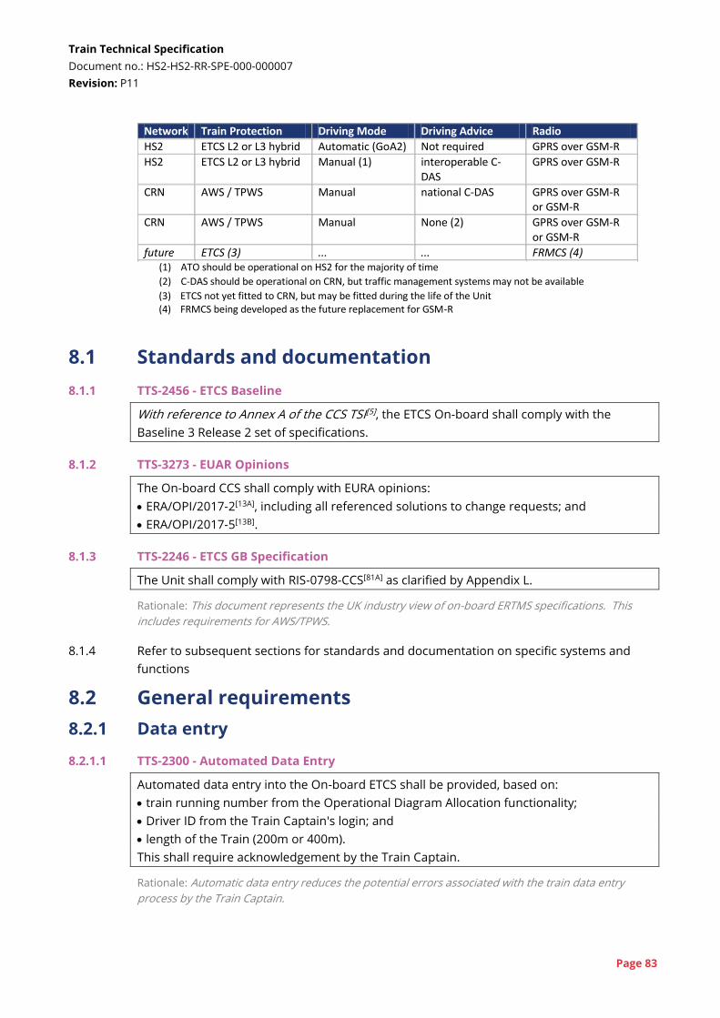
Train Technical Specification
Document no.: HS2-HS2-RR-SPE-000-000007
Revision: P11
Page 83
Network Train Protection Driving Mode Driving Advice Radio
HS2 ETCS L2 or L3 hybrid Automatic (GoA2) Not required GPRS over GSM-R
HS2 ETCS L2 or L3 hybrid Manual (1) interoperable C-DAS
GPRS over GSM-R
CRN AWS / TPWS Manual national C-DAS GPRS over GSM-R or GSM-R
CRN AWS / TPWS Manual None (2) GPRS over GSM-R or GSM-R
future ETCS (3) ... ... FRMCS (4) (1) ATO should be operational on HS2 for the majority of time
(2) C-DAS should be operational on CRN, but traffic management systems may not be available
(3) ETCS not yet fitted to CRN, but may be fitted during the life of the Unit (4) FRMCS being developed as the future replacement for GSM-R
8.1 Standards and documentation
8.1.1 TTS-2456 - ETCS Baseline
With reference to Annex A of the CCS TSI[5], the ETCS On-board shall comply with the
Baseline 3 Release 2 set of specifications.
8.1.2 TTS-3273 - EUAR Opinions
The On-board CCS shall comply with EURA opinions:
ERA/OPI/2017-2[13A], including all referenced solutions to change requests; and
ERA/OPI/2017-5[13B].
8.1.3 TTS-2246 - ETCS GB Specification
The Unit shall comply with RIS-0798-CCS[81A] as clarified by Appendix L.
Rationale: This document represents the UK industry view of on-board ERTMS specifications. This
includes requirements for AWS/TPWS.
8.1.4 Refer to subsequent sections for standards and documentation on specific systems and
functions
8.2 General requirements
8.2.1 Data entry
8.2.1.1 TTS-2300 - Automated Data Entry
Automated data entry into the On-board ETCS shall be provided, based on:
train running number from the Operational Diagram Allocation functionality;
Driver ID from the Train Captain's login; and
length of the Train (200m or 400m).
This shall require acknowledgement by the Train Captain.
Rationale: Automatic data entry reduces the potential errors associated with the train data entry
process by the Train Captain.
Train Technical Specification
Document no.: HS2-HS2-RR-SPE-000-000007
Revision: P11
Page 84
Cross-reference: See also Section 9.2 (Diagram allocation)
See also Requirement TTS-3503 (Automatic Data Entry - Radio) in Section 8.10 (Voice radio)
8.2.1.2 TTS-2301 - Preset Manual Data Entry
If automated data entry is not available, presets shall be provided to the Train Captain that
cover the two normal Train formations and possible rescue formations and degraded
operation modes.
Rationale: The preferred option for fixed formation units is to have automatic data entry but if this
functionality is not available, fixed data should be used since it minimises the risks associated with
data collection and incorrect entry by the Train Captain. During abnormal operation (e.g. rescue)
automatic data entry will not be available and hence the Train Captain will have to enter data.
8.2.2 Driver Machine Interface (DMI)
8.2.2.1 TTS-2303 - Speed Indication Transition
During any transition between ATO, ETCS and AWS/TPWS and between possible odometry
sources, the position of the speed indicator on the DMI shall not alter as a result of the
changeover process.
Rationale: Speed will need to be displayed in either km/h or mph depending on the mode. The
'needle' should not change position when the measurement units change.
8.2.2.2 TTS-2305 - Redundant Display
If DMI functionality is provided on a second DMI, the second DMI shall show the same
information with the same size, layout and format as the main DMI.
Rationale: Failure of the DMI is a potentially significant failure, and use of another in-cab screen (e.g.
the train control interface screen) to mitigate this is often adopted. This second screen must have
the same display as the main DMI to ensure a common interface for the Train Captain and not be
compressed, split or otherwise changed.
8.2.2.3 TTS-2306 - Fault Indications on DMI
Visual fault indications on the DMI shall not be suppressed at any time other than during
isolation of the faulty sub-system.
Rationale: This requirement will contribute to efficient driving.
8.2.2.4 TTS-2307 - On-board CCS Sub-components' Status
The Train Captain shall be able to access a maintenance menu on the DMI that will indicate
the status of the On-board CCS sub-systems.
Rationale: This requirement will support operational performance by quickly identifying On-board
CCS or CCS Trackside failures.
8.2.2.5 TTS-2269 - Secondary DMI
The Cab shall permit a temporary installation of a second DMI for the Instructor.
Rationale: During driver training, the Instructor will require clear visibility of the DMI display, including
both the main display and a temporary secondary display, such as a laptop screen showing the DMI.
Train Technical Specification
Document no.: HS2-HS2-RR-SPE-000-000007
Revision: P11
Page 85
Cross-reference: See also Requirement TTS-2027 (Instructor Visibility - ETCS DMI) in Section 10.9.2
(Cab sightlines)
8.2.3 Wheel calibration
8.2.3.1 TTS-2323 - Odometry Calibration
Odometry calibration shall not require specific additions or changes to the HS2 Network or
the CRN.
Rationale: It is preferable for the On-board CCS solution to re-calibrate itself automatically to account
for a reduction in wheel diameters as wheels wear. The HS2 Network will not include provision to
facilitate an automatic calibration system (see also TTS-2324, TTS-2325 and TTS-2326) for the On-
board CCS solution. Automatic calibration systems can rely only upon the ETCS/ATO infrastructure
that would otherwise be available. Eurobalises will not be located to any higher accuracy than that
stated against Q_NVLOCACC or Q_LOCACC; however, the value for Q_LOCACC is expected to be more
accurate in ATO specific areas.
8.2.3.2 TTS-2324 - Automatic Odometry Calibration 1
Automatic calibration of the wheel diameter shall not lead to different speeds calculated by
the ETCS On-board and ATO On-board.
Rationale: This functionality ensures consistency between ATO and ETCS speed calculation.
Cross-reference: See also Requirement TTS-100 (ATO Stopping Accuracy) in Section 8.6.4 (ATO
stopping accuracy)
8.2.3.3 TTS-2325 - Automatic Odometry Calibration 2
Automatic calibration of wheel diameter shall be sufficiently accurate to support the
stopping accuracy requirements.
Rationale: This functionality ensures consistency between different systems’ measurements (e.g.
ETCS and ATO).
8.2.3.4 TTS-2326 - Automatic Odometry Calibration 3
When automatically calibrating wheel diameter, erroneous values of wheel diameter shall
be automatically detected and corrected (e.g. by repeating calibration).
Rationale: Inconsistent measurement of wheel diameter should not impact operations.
8.2.3.5 TTS-3507 - Automatic Odometry Calibration 4
The Unit shall automatically recalibrate the ETCS odometry in response to wheel wear.
Cross-reference: See also Section 8.9 (Independent C-DAS)
8.2.4 Communication requirements
8.2.4.1 The installation of CCS antennas should consider GK/GN0602. This provides guidance on
positioning to avoid interference.
Train Technical Specification
Document no.: HS2-HS2-RR-SPE-000-000007
Revision: P11
Page 86
8.2.5 Future capability
8.2.5.1 TTS-2371 - Data Radios
A minimum of Three Edge-capable GSM-R/GPRS Data Only Radios (EDORs) shall be
provided.
Rationale: It is necessary to have two data only radios for ETCS and one for ATO. The second radio
for ETCS is to enable communication with a second RBC.
8.2.5.2 TTS-470 - Additional Space for Future Equipment
Additional space shall be provided for the fitment of future CCS / ATO equipment close to
each ETCS EVC installation. This space shall be equipped with 19" rack mounts and provide
a minimum of 6U of height and 450mm depth. There shall be 1U ventilation space above
and below the space provided.
Rationale: There may be a need in the future to upgrade the functionality of the on-board equipment
which requires additional components to be fitted to the Unit and connected to existing signalling
equipment.
8.2.5.3 TTS-2376 - Future Flexibility - 'Future Rail Mobile Communications System (FRMCS)
The Unit shall be capable of being migrated to the FRMCS. This shall allow for a situation
where current GSM-R/GPRS is used in some locations alongside FRMCS in others.
Rationale: FRMCS is the project to develop a successor to GSM-R (http://uic.org/frmcs)
8.2.6 On-board CCS Performance
8.2.6.1 TTS-3031 - CCS Accuracy for Distances
The accuracy of distance measured on-board shall better than or equal to ± (5m + 1% s), i.e.
the over reading amount and the under reading amount shall be equal to or lower than
(5m + 1% s), where 's' is the measured distance.
Rationale: This is a modification of Performance Requirements for Interoperability[16A] Clause 5.3.1.1
to support the CCS functionality required on the HS2 Network.
8.2.6.2 TTS-3411 - ATO Accuracy at ATO Passing Points
The Unit shall achieve an accuracy of measured Train location at ATO passing points that is
better than or equal to ± 1 m.
8.2.6.3 TTS-3412 - Accuracy of Train Speed
The Unit shall achieve an accuracy of measured Train speed that is better than or equal to
± 2 km/h at all possible speeds, provided that there is no wheel slip/slide and there are no
equipment failures,
Train Technical Specification
Document no.: HS2-HS2-RR-SPE-000-000007
Revision: P11
Page 87
8.3 ETCS
8.3.1 ETCS functions
8.3.1.1 TTS-234 - ETCS (PQTS-238) - Mandatory
The Unit shall be authorised to operate at the following ETCS application levels:
Level NTC;
Level 0;
Level 1;
Level 2; and
Level 3.
Rationale: Level NTC is required for initial operation on the CRN. Level 0 is required for shunting and
rescue. Level 1 is required for operation at the exit of the depot. It is currently planned that the HS2
Network will operate in ETCS Level 2, but ETCS Hybrid Level 3 (described in [22A]) may be adopted in
order to allow a reduction in trackside train detection equipment. It is planned to fit ETCS to the CRN
during the life of the Unit.
8.3.1.2 TTS-2255 - Integrity Function Performance
The on-board train integrity system for ETCS Level 3 shall be:
SIL4; or
compliant with future versions of the CCS TSI that include requirements for on-board
train integrity monitoring.
Rationale: The integrity of the train integrity system is not yet specified as part of Level 3 functionality.
8.3.1.3 TTS-2257 - ATO ETCS Service Brake Inhibit
When ATO On-board is Engaged (EG), the ETCS On-board shall inhibit the calculation of the
service brake intervention limits (SBI1 and SBI2).
Rationale: This is required to enhance ETCS performance.
8.3.1.4 TTS-2258 - Braking Correction Factor
The correction factor Kdry_rst shall be obtained using Monte Carlo methodology.
Rationale: The tolerance and reliability of the brake system is captured within the ETCS parameter
Kdry_rst which has a direct impact on the assumed deceleration of the Train. Monte Carlo analysis is
specified to ensure the calculated performance is as high as possible, thus maximising capacity.
8.3.2 ETCS performance
8.3.2.1 The following timings are specified for the ETCS On-board sub-system to support overall
times specified for the Unit in section 9.7.3.
8.3.2.2 TTS-2309 - ETCS Power-up Time
The ETCS On-board system shall take no more than 75 seconds to go from No Power (NP)
mode to requesting a Movement Authority (MA).
Rationale: The RBC will grant the Movement Authority so delay to obtain FS MA will depend on
trackside delays.
Train Technical Specification
Document no.: HS2-HS2-RR-SPE-000-000007
Revision: P11
Page 88
8.3.3 Key management
8.3.3.1 TTS-2330 - Key Management - Receive Updates
The On-board CCS shall be capable of accepting both on-line and off-line key management
updates from the Key Management Centre.
Rationale: It may be necessary to use on-line key management to achieve sufficient cyber-security.
8.3.3.2 TTS-2331 - Key Management Centre Identification
The On-board CCS shall be capable of identifying the correct Key Management Centre.
8.3.3.3 TTS-2332 - Key Management - Request Updates
The On-board CCS shall be capable of requesting an on-line update for the on-board keys
to the correct Key Management Centre at any time.
Rationale: The HS2 Units will be operated on both the HS2 Network and the CRN, which will be
managed by NR Key Management System.
8.4 AWS / TPWS
See also GE/RT8075[103]
8.4.1 TTS-236 - Conventional Signalling Systems (PQTS-242) - Mandatory
The Unit shall be fitted with AWS/TPWS equipment for operation on the CRN.
Rationale: The CRN routes are currently fitted with three/four aspect lineside signalling with AWS and
TPWS (defined by GE/RT8075). These systems may be upgraded to ETCS within the life of the Unit.
8.4.2 TTS-2337 - AWS/TPWS DMI Integration
The AWS/TPWS cab desk displays shall be integrated onto the ETCS DMI.
Rationale: A single DMI for use at all times is considered to be the preferred solution from a human
factors perspective.
8.4.3 TTS-3139 - AWS/TPWS Standard
The DMI for the AWS/TPWS On-board system shall have functionality and layout as defined
in RIS-0775-CCS[79] Part 5.
Rationale: CRN interface - Compliance with the RIS ensures an interface that is consistent with other
UK rolling stock and that adopts best practice for AWS/TPWS
8.4.4 TTS-2336 - AWS/TPWS with EVC Isolation
The AWS/TPWS, including the DMI, shall be available whether or not the EVC is isolated.
Rationale: This requirement ensures that even when the EVC is isolated, it is possible to run the
service on the CRN.
8.4.5 TTS-2335 - No Suppression in NTC SH Mode
The AWS/TPWS shall not be suppressed when the ETCS On-board is in Level NTC Shunting
(SH) mode.
Train Technical Specification
Document no.: HS2-HS2-RR-SPE-000-000007
Revision: P11
Page 89
Rationale: Some AWS/TPWS implementations permit AWS/TPWS to be suppressed when the unit is
shunting. This functionality should not be possible.
8.4.6 TTS-2339 - AWS/TPWS Power-up Tests
The ETCS On-board shall not prevent AWS/TPWS power-up tests from being undertaken
when the ETCS On-board is in Standby (SB), Isolation (IS) or No Power (NP) modes.
Rationale: This requirement contributes to the performance requirements on the CRN.
8.5 Protection during HS2-CRN transition
8.5.1 TTS-237 - Signalling Transition - Speed (PQTS-41)
The Unit shall be able to transition from the ETCS on the HS2 Network and to AWS/TPWS
on the CRN, and vice-versa at all speeds up to Maximum Line Speed.
Rationale: HS2 Trains will need to transition between the HS2 Network and CRN (and vice versa)
without needing to stop in the transition zone.
8.5.2 TTS-238 - Signalling Transition - Continuous Protection (PQTS-294)
Throughout each train protection system transition the Unit shall remain protected by at
least one of the train protection systems.
Rationale: The Trains must always under the protection of one of the applicable signalling systems.
8.5.3 TTS-437 - Failure to Transition Reporting
Failure of the Unit to complete a transition between protection systems shall be recorded
as an Event.
Rationale: Failures will need to be investigated as soon as possible to ensure the disruption is
minimised.
8.5.4 TTS-1742 - Transition Self-Test
The Units shall include the ability to run a self-test in advance of making a transition or in
the depot to provide prior warnings of any failures that could prevent the Unit from
transitioning to or from the HS2 Network.
Rationale: Failures that could prevent a Train from transitioning to or from the HS2 Network are likely
to have a significant impact on the operation of the railway. Early warning of these failures is key to
putting appropriate mitigation in place.
8.6 ATO
8.6.1 ATO functions
8.6.1.1 TTS-2341 - ATO GoA Level - Mandatory
The ATO On-board shall support Grade of Automation (GoA) 2 functionality.
8.6.1.2 TTS-2248 - EU ATO Specifications
The ATO On-board and Interoperable C-DAS shall be compliant with the ATO over ETCS
European development, specifically:
Train Technical Specification
Document no.: HS2-HS2-RR-SPE-000-000007
Revision: P11
Page 90
UNISIG specifications for ATO [19] [20] [21];
the release notes [21A];
amendments to existing specifications [18]; and
glossary document [15],
except where modified by requirements of this TTS.
Rationale: These documents represent the European industry view of ATO On-board specifications.
8.6.1.3 TTS-2249 - GB ATO Specification
The ATO On-board system shall be compliant with the ATO – GB New Trains Onboard
Subsystem Requirements Specification[22].
Rationale: This document represents the UK view of ATO On-board specifications.
8.6.2 ATO Stop and Safe Location
8.6.2.1 ATO Stop is an additional function compared to the ATO over ETCS SRS[19]. The purpose of
this function is to enable the Train Captain to command the Train to stop at the next Safe
Location. A Safe Location is a pre-defined location on the HS2 Network where Trains can
wait safely, and evacuation can be carried out if necessary. If it is not necessary to make an
emergency brake application, this enables more control of where Trains make un-planned
stops.
8.6.2.2 TTS-2359 - ATO Stop Button
An ATO Stop control shall be provided on the cab desk. (This is in addition to the ATO
Disengage input specified by ATO over ETCS SRS[19] Clause 8.1.1.4.)
Rationale: This enable the Train Captain to command the ATO to bring the Train to a stop, under the
ATO's control.
8.6.2.3 TTS-2356 - ATO Stopping
If the Train Captain presses the 'ATO Stop' control, the ATO On-board shall automatically
stop the Train at the next Safe Location at which the Train can stop at full service brake
deceleration.
8.6.2.4 TTS-3110 - ATO Stop Report
The ATO On-board shall report to the ATO Trackside when the ATO Stop control is
activated.
Rationale: This is to enable an alarm to be triggered at the NICC. It is expected that the Train Captain
will contact the traffic management controller in the NICC to explain the on-board issue.
8.6.2.5 TTS-3111 - ATO Stop Planned Location
When the ATO Stop control is activated, the ATO On-board shall report to the ATO
Trackside the location (i.e. the Safe Location) where the Train is expected to stop.
Train Technical Specification
Document no.: HS2-HS2-RR-SPE-000-000007
Revision: P11
Page 91
8.6.2.6 TTS-3112 - ATO Stop Actual Location
When the Train has stopped following activation of the ATO Stop control, the ATO On-
board shall report the Train's location, as determined by the On-board CCS, to the ATO
Trackside.
Rationale: For controlled stop in a tunnel, this would allow the tunnel ventilation system to be
configured around the stopping position.
8.6.3 Transitions between networks
8.6.3.1 TTS-2342 - HS2-CRN Transition
When a Train transitions from the HS2 Network to the CRN:
the ATO On-board shall transition to Disengaging (DE) state;
the Train Captain shall be required to select "ATO Disengage" or make a brake application
within 5 seconds; and
the Train shall continue at its current speed, unless a brake application is made by the
Train Captain.
The ATO On-board shall not cause the Train to stop if the transition is performed correctly.
If the Train Captain does not select "ATO Disengage" or make a brake application, the ATO
On-board shall apply a full service brake.
Rationale: This functionality is based on the "Losing ATO Operational Conditions" scenario described
in ATO over ETCS SRS[19] Section 9.10.3.
8.6.3.2 TTS-3378 - CRN-HS2 Transition
When a Train transitions from the CRN to the HS2 Network:
the ATO On-board shall transition through to ATO Ready (RE) state;
the Train Captain shall select "ATO Engage"; and
the ATO On-board shall change to ATO Engaged (EG) state.
It shall not be necessary to stop the Train through this process.
8.6.4 ATO stopping accuracy
8.6.2.1 The performance criteria in this section are based on standards[70] [75] for similar systems.
8.6.4.2 TTS-100 - ATO Stopping Accuracy (PQTS-122)
When ATO On-board stops the Train at a Stopping Point that is a station, the Unit shall
achieve the following stopping accuracies:
± 0.50 m for 99.997% of all station stops;
± 0.75 m for 99.9993% of all station stops; and
± 1.00 m for 99.9999% of all station stops;
when making a stop at any rate up to full service brake deceleration.
Rationale: HS2 interface - This level of accuracy is necessary for compatibility with a PEP system.
Since this is still under consideration, the Unit will need to capable of achieving this. If low adhesion
is reported (i.e. lower than specified in the LOC&PAS TSI[4] (as defined in TTS-101) the ATO will require
a lower brake rate.
Train Technical Specification
Document no.: HS2-HS2-RR-SPE-000-000007
Revision: P11
Page 92
Cross-reference: See also Requirement TTS-101 (Full Service Brake Performance (HS2)) in Section 7.3
(Braking)
See also Requirement TTS-2276 (Poor Adhesion Response) in Section 8.6.5 (Other ATO functions)
See also Requirement TTS-3144 (Report WSP in Automatic Mode) in Section 9.10 (Brake control)
8.6.4.3 TTS-3095 - BTM Design
The balise transmission module shall use the 'balise reference mark' or the highest point of
the 'Eurobalise main lobe zone' to recalibrate the odometry subsystem.
Rationale: This functionality supports odometry performance requirements for ATO.
8.6.4.4 TTS-2349 - Stopping Adjustment
When the Train comes to a stop at a Stopping Point, if the Train has either:
overrun the Stopping Point by a distance less than a maximum overrun distance; or
stopped short of the Stopping Point,
the On-board ATO shall not disengage and shall automatically re-align the Train with the
Stopping Point.
Rationale: This contradicts ATO over ETCS[19] Clause 7.1.4.4. This is necessary to achieve the required
level of service reliability. Automatic re-alignment will minimise delays caused by inaccurate stopping
at platforms. A maximum overrun distance will be defined. Provided the overrun is less than this, the
Train should move backwards to re-align. Beyond this maximum overrun distance, manual re-
alignment will be required.
Cross-reference: See also Requirement TTS-3031 (CCS Accuracy for Distances) in Section 8.2.6 (On-
board CCS Performance)
8.6.4.5 TTS-2350 - Stopping Approach Adjustment
The ATO On-board shall adjust the Automatic Train Stopping Management, if the Train has
overrun three stopping points consecutively.
Rationale: This is to achieve the required level of service reliability. A number of factors which are
random in nature can cause degradation of the stopping accuracy. This can cause delays and
adversely impact service reliability. This function intends to compensate the performance
degradation by automatically adjusting the speed profile on approach to stopping points.
8.6.5 Other ATO functions
8.6.5.1 TTS-2344 - ATO Isolation
The ATO On-board shall not fail in a way that interferes with manual driving or ETCS On-
board.
This shall be achieved by enabling the Train Captain to isolate the ATO On-board.
Rationale: The ATO On-board is not required to have the same integrity as ETCS On-board. It is
possible that ATO On-board could provide traction demands when not intended. The Train Captain
must be able to isolate the ATO to prevent this.
8.6.5.2 TTS-2346 - No Traction Out of ATO
When the ATO On-board exits Engaged (EG) state, the Train shall not respond to any
traction demand from the traction-brake controller until the controller has first been
returned to the neutral / coast position.
Train Technical Specification
Document no.: HS2-HS2-RR-SPE-000-000007
Revision: P11
Page 93
Rationale: The ATO over ETCS operational concept requires that selecting braking will disengage the
ATO, but selecting traction will have no impact. If traction is selected for more than 5 seconds, an
alarm should be sounded - ATO over ETCS SRS[19] Clauses 8.2.9.1 / .2. If the traction/brake controller
is moved to the traction position and then ATO disengages, the Train could respond to the traction
demand unless this is suppressed. This requirement is not currently included in the ATO over ETCS
SRS.
8.6.5.3 TTS-2276 - Poor Adhesion Response
The ATO On-board shall be capable of modifying the ATO Operational Speed Profile and
traction / braking commands according to “low adhesion information” received from the
ATO Trackside, as specified in ATO over ETCS SRS[19] Section 7.6.
Rationale: This requirement permits ATO brake and acceleration rates to be modified in low adhesion
conditions. The decision to lower rates will be made by the traffic controller. The commands may be
sent to one Train or several Trains in an area.
8.6.5.4 TTS-2352 - Automatic Speed Reduction
The ATO Traction / Brake Control shall take account of any speed restrictions that are
necessary due to exceptional conditions or failures with the Rolling Stock (e.g. deflated
secondary suspension).
The Train Captain shall be given a warning that the speed limit has been applied.
Rationale: This function is intended to implement temporary rolling stock speed restrictions due to
high payloads or failures. It is anticipated that another system would have to enforce the speed
restriction, but the ATO On-board should not attempt to overcome this.
8.6.5.5 TTS-2353 - Automatic Payload Adjustment
The ATO Traction / Brake Control shall take account of the Train payload information when
defining the ATO output commands, unless traction and braking sub-systems already
account for payload.
Rationale: This enables efficient driving with the optimum energy consumption.
8.6.5.6 TTS-2310 - Automation of Preparation and Stabling
The On-board CCS shall provide functionality for automation of the preparation and
stabling processes, including changes of Train direction.
Rationale: This is specified in the ATO over ETCS Operational Requirements[17] (3.1, 3.2 and 5.1) and
includes 'Automatic Start of Mission' and 'Automatic End of Mission' functionality. This functionality
will speed-up station turnarounds and transfers into and out of service.
8.6.5.7 TTS-2354 - Expected Arrival Time Information
The ATO On-board shall be able to provide next station, expected arrival time and other
similar information to other systems on the Unit.
Rationale: This information can be used by the PIS.
Cross-reference: See also Requirement TTS-2878 (AIP Through Journey) in Section 9.25.3 (Automatic
Information Programme (AIP))
8.6.5.8 There are other requirements in Section 9 of the TTS related to ATO.
Train Technical Specification
Document no.: HS2-HS2-RR-SPE-000-000007
Revision: P11
Page 94
Cross-reference: See also Requirement TTS-318 (Automatic Door Control) in Section 9.18.2 (Train-
wide door control)
See also Requirement TTS-488 (Vigilance - Driving Modes) in Section 8.11 (Other protection systems)
See also Requirement TTS-946 (Automatic Sanding Activation) in Section 9.12 (Sanding and adhesion
control)
See also Requirement TTS-1400 (ODA Auto Login) in Section 9.2 (Diagram allocation)
See also Requirement TTS-1761 (Vigilance - Adjust X Value) in Section 8.11 (Other protection systems)
See also Requirement TTS-2039 (Report WSP) in Section 9.10 (Brake control)
See also Requirement TTS-2472 (PEP System Interlock) in Section 9.19.2 (Door and PEP control)
See also Requirement TTS-2497 (Data Recording - Delay) in Section 9.5.2 (Data recording)
See also Requirement TTS-2751 (Standing in ATO) in Section 10.9.1 (Cab design)
See also Requirement TTS-2878 (AIP Through Journey) in Section 9.25.3 (Automatic Information
Programme (AIP))
See also Requirement TTS-2942 (AIP Journey Time Update) in Section 9.25.3 (Automatic Information
Programme (AIP))
See also Requirement TTS-3144 (Report WSP in Automatic Mode) in Section 9.10 (Brake control)
See also Requirement TTS-3383 (Vigilance - Variable X Value) in Section 8.11 (Other protection
systems)
8.7 Manual driving (GoA1)
8.7.1 The Train will be manually driven when it is operating on the CRN and on some occasions
on the HS2 Network. Requirements for manual control of the Train are contained in the
LOC&PAS TSI[4] with an additional function below.
Rationale: It is envisaged that there may be certain scenarios where manual driving is required on the
HS2 Network.
Cross-reference: See also Section 9.10 (Brake control)
See also Section 9.9 (Traction control)
8.7.2 TTS-2177 - Set Speed Control
The Unit shall have a 'Set Speed' function that allows the Train Captain to set a fixed speed
that the Unit will maintain using traction and braking until the function is cancelled.
Rationale: This will support the Train Captain through long sections with a constant speed limit.
8.7.3 TTS-3428 - Speed Limiter
The Unit shall have a speed limiter function that limits the maximum speed of the Train
while giving the Train Captain full control of traction and braking up to that limit.
Rationale: This would enable a temporary speed restriction to be enforced on the CRN (this function
can be achieved via ETCS on the HS2 Network).
8.8 Shunting
8.8.1 TTS-1485 - Slow Speed Control
The Unit shall have a speed control function that allows a low maximum speed to be set
and allows the speed of the Unit to be held at this limit.
Rationale: It is envisaged that this would be used for operation in depots, sidings and for moving
through wash plants.
Train Technical Specification
Document no.: HS2-HS2-RR-SPE-000-000007
Revision: P11
Page 95
8.8.2 TTS-1575 - Slow Speed Adjustment
The Train Captain shall be able to adjust the slow speed control (TTS-1485) in increments of
1km/h up to a maximum 25km/h, and select a pre-set 'train wash' speed that is adjustable
as an Operator Setting.
8.8.3 TTS-2030 - Automatic Depot Speed Limit
It shall be possible to automatically apply a maximum value for slow-speed control
depending on the depot the Unit is currently located in.
Rationale: Different depots may have different maximum speed limits.
8.8.4 TTS-415 - Reverse Driving
It shall be possible to manually drive the Train in reverse, i.e. away from the Active Cab.
In this mode, the Train shall apply a speed limit.
The speed limit shall be adjustable via a Software Update.
Rationale: This is intended to be used for depot and shunting operations or situations where a Train
needs to be manually set back at a station. The full operational controls to support this movement
need further development.
8.8.5 TTS-1579 - Reverse Driving CCTV
When moving in reverse, images from the FFRF CCTV camera(s) in the rear Cab shall be
displayed to the Train Captain.
Rationale: This is to allow the Train Captain visibility of the direction of travel.
Cross-reference: See also Section 9.26.2 (FFRF CCTV)
8.8.6 TTS-3191 - Reverse Driving Windscreen Wipers
When moving in reverse, it shall be possible to activate the means of clearing the view of
the FFRF CCTV camera(s) (e.g. windscreen wipers) on the rear Cab from the Active Cab.
Rationale: If the FFRF CCTV is used for rear visibility, it must be possible to ensure a clear view.
Cross-reference: See also Requirement TTS-597 (Keep FFRF Cameras Clear) in Section 9.26.2 (FFRF
CCTV)
8.9 Independent C-DAS
8.9.1 Independent C-DAS is described in RIS-0711-CCS[78A]. Of the sub-systems described in that
document, the TMM is required to provide the C-DAS Onboard. The C-DAS Onboard will
interface with the C-DAS RU Trackside; this interface will be developed in accordance with
MSA Schedule 11.
8.9.2 TTS-244 - Connected Driver Advisory System (C-DAS) (PQTS-44)
The Unit shall include an Independent C-DAS Onboard that will provide advice to the Train
Captain when driving manually on the CRN.
Rationale: Correct presentation of Trains at junctions with the HS2 Network is necessary to achieve
the high reliability of operations on the HS2 Network. Furthermore, achievement of consistent, on-

Train Technical Specification
Document no.: HS2-HS2-RR-SPE-000-000007
Revision: P11
Page 96
time running based on real-time railway conditions and the possibility of delivering energy efficiency
are key to overall goals of the High Speed 2 Project.
8.9.3 TTS-2885 - Compliance with Independent C-DAS Specification
The Independent C-DAS Onboard shall comply with the Interim System Requirements
Specification for C-DAS[107].
8.9.4 TTS-477 - Independent C-DAS Information to Train
The Independent C-DAS Onboard shall enable the receipt of schedule, routing and speed
restriction updates by the Train in near-realtime, with information presented to the Train
Captain to ensure on time running.
Rationale: In order to deliver correct presentation of trains at the HS2 Network it is envisaged that a
C-DAS system will be required to deliver dynamic advice to the Train Captain.
8.9.5 TTS-3366 - Independent C-DAS Default Information
In an area where there is no data provided by a network operation centre, the Independent
C-DAS Onboard shall operate with the most recent updates received from a control centre
or pre-configured data.
8.9.6 TTS-3024 - C-DAS Visualisation
The Independent C-DAS Onboard shall present information on the ETCS DMI.
Rationale: This is intended to reduce cognitive workload associated with moving between the CRN
and the HS2 Network by ensuring the Train Captain is always provided with driving information on
the same display.
8.10 Voice radio
See also CCS TSI[5]
8.10.1 TTS-481 - Compatibility with GSM-R - Mandatory
The Unit shall be equipped with a voice radio system capable of GSM-R communication.
Rationale: The GSM-R voice radio shall allow the Train Captain to communicate with the signaller, for
the passing of urgent safety-related data between the Unit and the Wayside and to fulfil emergency
communication capability requirements.
8.10.2 TTS-2250 - GSM-R RIS Specification
The GSM-R Voice Radio On-board shall be compliant RIS-0794-CCS[81].
8.10.3 The Unit shall achieve requirements TTS-3503, TTS-2057 and TTS-2517 provided that the
standard Network Rail GSM-R Voice Radio has been developed to enable this functionality.
This development is not the responsibility of the TMM.
8.10.4 TTS-3503 - Automatic Data Entry - Radio
Automated data entry into the GSM-R Voice Radio On-board shall be provided, based on
both:
automated data entry into the On-board ETCS (TTS-2300); or
Train Technical Specification
Document no.: HS2-HS2-RR-SPE-000-000007
Revision: P11
Page 97
manual data entry into the Onboard ETCS.
8.10.5 TTS-2057 - GSM-R Voice Radio Volume Adjustable
With reference to RIS-0794-CCS[81] Clause 8.2.27.1 and EIRENE SRS[14] Clause 5.4.5, the
handset and loudspeaker volume shall be capable of automatic adjustment based on the
measured or predicted ambient cab noise.
The volume shall also be manually adjustable by the Train Captain.
Rationale: Train Captains will have preferences over volume levels. The ambient noise in the cab is
likely to vary considerably between low speed and very high speed in tunnels.
Cross-reference: See also Section 9.7.4 (Train Captain settings)
8.10.6 TTS-2517 - Recording of GSM-R Coverage Loss
The loss and re-establishment of GSM-R coverage shall be recorded.
8.11 Other protection systems
8.11.1 A Driver’s Reminder Appliances (DRA), as defined by GM/RT2491[94], is required by the
current list of notified national technical rules.
Rationale: CRN interface - A DRA device is deemed to be required for operation on the CRN
8.11.2 TTS-486 - Driver's Reminder Appliance (DRA) Functionality
When the DRA is reset, there shall be a warning to the Train Captain in the form of a
recorded voice message “DRA off – Driver check signal.”
Rationale: This functionality is intended to assist the Train Captain in ensuring it is safe to proceed.
8.11.3 TTS-488 - Vigilance - Driving Modes
With reference to LOC&PAS TSI[4] Section 4.2.9.3.1, the 'driver's activity control' (vigilance)
function shall be configurable to :
operate at all times as specified in the LOC&PAS TSI;
monitor activity at all times, but not make an emergency brake application when the ATO
On-board is Engaged (EG); and
operate only when ATO is not Engaged (EG).
Rationale: Whilst this functionality currently contravenes the LOC&PAS TSI[4], the capability to change
to this functionality, when permitted, will improve operation of the railway by the ability to take
alternative action if a Train Captain has become incapacitated when operating under ATO, e.g. by
moving the Train to a specific point of safety before stopping.
8.11.4 TTS-1760 - Vigilance - Communicate to Wayside
A lack of driver's activity and the failure of the Train Captain to cancel the warning shall be
communicated to the Wayside, whether or not a brake application is made.
Train Technical Specification
Document no.: HS2-HS2-RR-SPE-000-000007
Revision: P11
Page 98
8.11.5 TTS-1761 - Vigilance - Adjust X Value
With reference to LOC&PAS TSI[4] Clause 4.2.9.3.1 (2) ¶3, it shall be possible to set a
separate value of X (the time before an activity is required) for when ATO On-board is
Engaged (EG) and when it is not Engaged.
The value of X for when ATO On-board is Engaged shall be capable of being greater than 60
seconds.
Values of X shall be set as Operator Settings.
Rationale: It may be determined that when ATO is Engaged, activity monitoring is required, but at a
less frequent interval.
8.11.6 TTS-3383 - Vigilance - Variable X Value
When ATO On-board is Engaged (EG), the value of X (the time before an activity is required)
shall be capable of being set to a randomly changing value between two limits.
The limit values of X shall be set as Operator Settings.
Rationale: A constant value of X would mean the Train Captain would have a very repetitive
interaction while ATO is engaged. A variable value of X may lead to better engagement
8.11.7 Human factors assessment will be required to determine how best to apply the 'driver's
activity control' function while ATO On-board is active. Implementation in any way other
than that specified in the LOC&PAS TSI will be subject to updates to the TSIs to permit this
functionality or other regulatory approval that enables this. The above requirements
specify the capability to change the function, but such changes would not be implemented
without the necessary approvals. Refer to Appendix O.
9 Functionality and systems 9.0.1 The functionality of the Unit, its interactions with Passengers, the Train Captain and other
Train Crew, and its integration with the Wayside will be developed by the TMM in
partnership with the Purchaser, the HS2 Train Operator and other stakeholders in the HS2
project according to the functional integration process described in MSA Schedule 11.
9.0.2 The TTS defines the high-level functions to be achieved. The TMM will develop the detailed
functionality that achieves these functions and integrates all systems.
9.0.3 The majority of functionality requirements apply to the Unit as an operational Train, which
may comprise one Unit or two coupled Units. Requirements refer to 'Unit' or 'Train'
accordingly. Where requirements refer to the Unit or Train, this includes On-board CCS
and Rolling Stock subsystems.
9.0.4 This section first sets out common train controls functions and principles, which are used
for most systems. It then defines requirements for driving the Train, followed by
requirements for each area of functionality.
Train Technical Specification
Document no.: HS2-HS2-RR-SPE-000-000007
Revision: P11
Page 99
9.1 Operator Settings and Software Updates
9.1.1 The functionality described in this TTS must be developed prior to Acceptance. However, it
is envisaged that some systems will need to permit changes to settings after Acceptance
without the need for formal modification. Such changes would be implemented by the
Operator to affect how the Unit interacts with Passengers, the Train Captain and Train
Crew. These are referred to as Operator Settings. Requirements through this section
make reference to functions being adjustable as an Operator Setting. The following
general requirements exist for Operator Settings where they are specified:
9.1.2 TTS-494 - Set Operational Vehicle Type
It shall be possible for Vehicles within a Unit to have different Operator Settings from each
other.
Rationale: This permits different vehicles to be allocated to different types of on-board service.
9.1.3 TTS-1362 - Update Operator Settings 1
It shall be possible to update Operator Settings from the Wayside.
Rationale: This is to prevent the need to visit each Unit to update it.
9.1.4 TTS-1361 - Update Operator Settings 2
It shall be possible to update Operator Settings on a single Unit, the Fleet or a number of
Units within the Fleet.
Rationale: It is envisaged that new settings may be trialled on a single Unit prior to roll-out across the
Fleet. In some cases this could introduce undesirable situations, and so all Units must be updated
together. These Operator Settings will need to be restricted to fleet-only so that all Units must be
updated together.
9.1.5 TTS-2079 - Temporary Operator Settings
It shall be possible to temporarily update Operator Settings for a particular Vehicle. The
updated settings would be set at Crew Control Points or received from the Wayside.
The updated settings shall reset at the end of the current Service.
Rationale: This would give the flexibility for some passenger-facing settings (HVAC set-point and
lighting levels are the most likely changes) to be adjusted either mid-journey or for a particular
journey.
9.1.6 There are further settings for which it would not be suitable to make changes without
suitable review, assurance and control. However, it is still required that these changes can
be made through changes to software alone. These are referred to as Software Updates -
see Section 9.29.
9.2 Diagram allocation
9.2.1 This section describes functionality required to permit individual Units to be allocated to
specific Operational Diagrams - the sequence of Services that a Unit will undertake in a
given day, including empty coaching stock (ECS) moves. Each Service is a journey between
Train Technical Specification
Document no.: HS2-HS2-RR-SPE-000-000007
Revision: P11
Page 100
two points with a number of intermediate stops. This functionality will need to be
developed with any traffic management systems that are implemented on the HS2
Network and the CRN.
Rationale: The functionality in this section is defined to simplify the process of the Train Captain and
Train Crew setting up a Unit. This will speed-up departure and should minimise the chance that
services leave with incorrect or missing passenger information. This functionality will also enable
Units to automatically prepare themselves for service, pre-heating and pre-cooling only when
required and minimise the overall energy consumption.
9.2.2 TTS-1392 - Operational Diagram Allocation
It shall be possible to allocate a Unit to a specific Operational Diagram on a specific date,
and time as required.
9.2.3 TTS-1564 - ODA - Multiple Unit Operation
Operational Diagram Allocation shall include multiple-unit operation, in which the order of
Units shall be planned and monitored.
Rationale: Certain services will be operated as two Units. The Units will need to configure themselves
for this arrangement, including opening and closing coupler covers at the appropriate points.
9.2.4 TTS-1395 - ODA - Control
A Unit shall receive its allocation to an Operational Diagram from the Wayside, and shall
store this on the Unit.
Rationale: This Unit should not be dependent on the connection to the Wayside to maintain this
functionality.
9.2.5 TTS-1393 - ODA - Time in Advance
It shall be possible to allocate Units to Operational Diagrams up to three months in
advance.
9.2.6 TTS-1394 - ODA Changes - Wayside
It shall be possible to change the allocation of a Unit to an Operational Diagram from the
Wayside in advance, between services or during a Service.
If the Unit is in a driving mode (i.e. it has an Active Cab) at the time of the change, the
change shall be displayed to the Train Captain and at any Crew Control Point.
Rationale: Changes to the planned diagram or route of Train may be made by the traffic
management system.
9.2.7 TTS-1396 - ODA Changes - On-board
It shall be possible for the Train Captain to change the allocation of a Unit to an
Operational Diagram.
If a change is made, this shall be communicated to the Wayside.
Train Technical Specification
Document no.: HS2-HS2-RR-SPE-000-000007
Revision: P11
Page 101
9.2.8 TTS-1397 - ODA - On-board Check
It shall be possible for the Train Captain and Train Crew to check which Operational
Diagram and Services a Unit has been allocated to, and which Service it is currently
operating.
9.2.9 TTS-3380 - ODA - On-board Check Information
For each Service which the Train Captain can check (TTS-1397), the Train Captain shall be
able to see at least the:
origin;
destination;
stopping points;
coupling/uncoupling locations;
preceding Service; and
following Service.
9.2.10 TTS-1400 - ODA Auto Login
The Unit shall automatically provide mandatory data to on-board systems, e.g. ETCS, ATO,
DAS and GSM-R voice radio based on its Operational Diagram allocation and the Service it
is operating.
The Train Captain shall be required to confirm this data.
9.2.11 TTS-1996 - ODA Crew Log
It shall be possible to add names or IDs of Train Captain and Train Crew for a particular
Service to an Operational Diagram.
It shall be possible to compare this data to crew logins.
9.3 On-board controls
9.3.1 This section sets out controls to be provided for the Train Captain and Train Crew. The
functionality of these controls is defined in other sections of the TTS.
9.3.2 TTS-1593 - Train Captain Controls
All controls for the Train Captain to operate the Train shall be included in the Cab.
9.3.3 TTS-1454 - Crew Control Point - Mandatory
The Unit shall have a Crew Control Point positioned close to the mid-point of the Unit.
The Crew Control Point shall include a colour touch screen for accessing a limited set of
information and controls, and a communications handset.
Rationale: It is assumed that the Cab will provide means to access train control systems. To enable a
faster response to issues that may arise on-board, access is required to some systems without Train
Crew needing to walk to a Cab at the far end of the Unit.
9.3.4 TTS-1594 - Crew Controls in Cab
Train Crew shall be able to use a subset of controls and equipment in an Inactive Cab to
access information from on-board systems.
Train Technical Specification
Document no.: HS2-HS2-RR-SPE-000-000007
Revision: P11
Page 102
9.3.5 TTS-1595 - Public Address Point
The Unit shall have public address points with a communications handset in Vestibules
arranged such that:
at least one public address point is provided in each Vehicle;
in Vehicles with Evacuation Doors, the handset shall be provided in the same Vestibule as
the Evacuation Doors; and
there is at least one public address point every 25m along the Unit.
Public address points shall not be accessible to the public.
Rationale: Train Crew will need to be able to make announcements and respond to calls throughout
the Unit.
9.3.6 TTS-1330 - Train Crew Door Control at Doorways
Three sets of controls for Train-wide door control, including a signal buzzer for
communication with the Train Captain, shall be provided for use by Train Crew.
Train-wide door controls shall be distributed at approximately 50m intervals throughout
the Unit.
Train-wide door controls shall be installed adjacent to Exterior Doorways inside the
Vestibule on both sides of the Vehicle.
Train-wide door controls shall not be accessible to the public.
Rationale: This is in addition to door controls in the Cab, for use by the Train Captain. Controls would
be approximately 50m, 100m and 150m along the Unit. The controls are required to support specific
train dispatch concepts.
9.3.7 TTS-2173 - Controls' Human Factors
The design of all controls, including the presentation of information and soft controls on
train control screens shall consider the human factors of the user of the controls.
Rationale: This high-level requirement is included to highlight that human factors needs to be
considered as part of the development of train controls.
9.4 Train to Wayside and passenger communications
9.4.0.1 This section contains requirements for three systems to enable non-critical and passenger
communications between the Unit and the Wayside. Whilst the functionality is split in to
three systems it is not required that they are physically separated and may share common
elements to allow optimisation of the overall design.
9.4.1 Non-Passenger communications
9.4.1.1 Non-passenger communications covered by this section are intended to include
communication required for all data related to the Wayside Data System including for
example, diagnostic data, CCTV data, Operator Settings, etc.
9.4.1.2 TTS-3304 - Train to Wayside Communications Interface
All non-safety critical, operational communication between the Unit and the Wayside and
Wayside Data System shall be capable of being transmitted via both:
Train Technical Specification
Document no.: HS2-HS2-RR-SPE-000-000007
Revision: P11
Page 103
WiFi when the Unit is within range of a suitable WiFi system (e.g. depot or station); and
public mobile networks.
Rationale: It is expected that the most accessible communications channel available to the Units will
be public mobile networks, including in HS2 tunnels, however WiFi may also be used for certain bulk
download activities at stations and/or depots.
9.4.1.3 TTS-3306 - Mobile Network Future Compatibility
Provision shall be made for Train to Wayside communications to be compatible with future
5G networks.
This provision shall as a minimum include suitable antennas and cabling to cover the
current range of frequencies anticipated for UK mobile operations in the range from
700MHz to 5GHz.
Rationale: The Units should be prepared as much as possible for future mobile network upgrades.
9.4.2 Passenger mobile communications
9.4.2.1 TTS-3308 - Digital On-board Repeater (D-OBR) - Mandatory
The Unit shall be fitted with a system capable of repeating and boosting mobile network
signals from outside the Unit to all areas of the Unit - a Digital On-board Repeater (D-OBR).
Any signal boosting capability shall include tuneable gain and filtering, echo cancellation
channel switching and noise cancellation appropriate to each band and configurable by
Location (Line & Distance).
9.4.2.2 TTS-3309 - D-OBR Coverage
The D-OBR shall be designed to ensure that there is sufficient coverage for the 1SL seating
capacity.
9.4.2.3 TTS-3310 - D-OBR Compatibility
The D-OBR shall be multiband compatible and capable of repeating and enhancing signals
in all bands and across all cellular standards for voice and data communications used by
UK public mobile operators.
Rationale: Passengers and Train Crew should have the ability to remain connected to high quality
public mobile network signals for as much of the journey as possible.
9.4.2.4 TTS-3311 - D-OBR Future Compatibility
Provision shall be made for the D-OBR to be compatible with future 5G networks.
This provision shall as a minimum include suitable antennas and cabling to cover the
current range of frequencies anticipated for UK mobile operations in the range from
700MHz to 5GHz.
Rationale: The Units should be prepared as much as possible for future mobile network upgrades.
Train Technical Specification
Document no.: HS2-HS2-RR-SPE-000-000007
Revision: P11
Page 104
9.4.3 Passenger WiFi communications
9.4.3.1 TTS-3313 - Public WiFi Network - Mandatory
Units shall be fitted with a system to provide WiFi to all passenger and staff areas within
the Unit - a Public WiFi Network.
Rationale: Passengers and Train Crew should have the option to use a public WiFi network to enable
communications via personal computers, smart phones, tablet computers or equivalents.
9.4.3.2 TTS-3305 - Mobile Network Compatibility
The Public WiFi Network shall communicate with public mobile networks and shall be 2G,
3G and 4G compatible and support the following:
LTE Carrier Aggregation;
Multiple-in / Multiple Out antennas for train to mobile network connectivity;
GNSS positioning; and
bonding of multiple connections.
Rationale: The Public WiFi Network should be able to maximise available bandwidth.
9.4.3.3 TTS-3314 - Public WiFi Network Capacity
The Public WiFi network shall be designed to ensure that, assuming the 1SL seating
capacity, all passengers can be connected to the system simultaneously and that the
bandwidth available to each user is maximised.
Rationale: Passengers and Train Crew should have the ability to continue to use their devices when
on-board. It is acknowledged that the final available bandwidth will be dependent on the network
coverage.
9.4.3.4 TTS-3324 - Future Flexibility - Public WiFi Network Expansion
The on-board network provided to support the Public WiFi Network systems shall be
capable of supporting a minimum of 10Gb/s. This shall include all cabling, switches and
gateway units.
Rationale: There should be scope for scaling of the system based on technology and equipment
available during the lifetime of the Units.
9.4.3.5 TTS-3315 - Public WiFi Network Mobile Network Future Compatibility
Provision shall be made for the Public WiFi Network to be compatible with future 5G
networks for transmission to the Wayside.
This provision shall as a minimum include suitable antennas and cabling to cover the
current range of frequencies anticipated for UK mobile operations in the range from
700MHz to 5GHz.
Rationale: The Units should be as prepared as possible for future mobile network upgrades.
9.4.3.6 TTS-3316 - Public WiFi Network Access Point Functionality
WiFi access points shall conform to IEEE 802.11 using the following protocols:
IEEE 802.11a (5.0 GHz);
IEEE 802.11b (2.4 GHz);
Train Technical Specification
Document no.: HS2-HS2-RR-SPE-000-000007
Revision: P11
Page 105
IEEE 802.11g (2.4 GHz);
IEEE 802.11n (2.4 GHz);
IEEE 802.11n (5.0 GHz); and
IEEE 802.11ac (5.0 GHz).
WiFi access points shall be able to dynamically allocate channels to minimise interference.
9.4.3.7 TTS-3317 - Public WiFi Network Access Point Upgradeability
The WiFi access point shall be flexible/expandable to support any future WiFi protocols.
Rationale: The Units should be as prepared as possible for future WiFi upgrades.
9.4.3.8 TTS-3320 - Public WiFi Network Content Server
An on-board content server shall be provided which shall interface with the Public WiFi
Network.
The content server should be able to host various content like video, audio and interactive
games and services.
Rationale: The Units should support a wide range of future operating scenarios.
9.4.4 Additional Data Communications System Provision
9.4.4.1 TTS-3318 - Provision for Additional Data Communications Systems - Mandatory
The Unit shall include provision for the fitment of an additional data communications
system. This provision shall be in the form of locations and interfaces to install one system
with the following characteristics in each of the leading Vehicles (i.e. two systems per Unit):
space allocation in the form of a 19" rack mount which is at least 4U high and a minimum
depth of 400mm. It shall be assumed that the equipment to be fitted will have a maximum
mass of 10kg;
the provision of a power supply of up to 3A at 110V DC;
physical interfaces and cabling to allow this additional system to be connected to the
Public WiFi Network;
physical interfaces and cabling to allow this additional system to be used for non-
passenger communications; and
accessible cable route to a location suitable for the future fitment of a roof mounted
antenna that has a line of sight in front of the leading Cab.
Rationale: The Units should be as prepared as possible for future technology changes. The HS2
Network or CRN may be fitted with a dedicated wireless communications system to enable high-
bandwidth communication with the Units. Such a system may require additional equipment to be
fitted to the Units. Passenger communications (using the Public WiFi Network on the Units) and non-
passenger communication (Section 9.4.1) would be expected to utilise the dedicated wireless
communication system at all locations where it is fitted, but would need to revert to infrastructure-
fitted WiFi or to public mobile networks elsewhere.
Train Technical Specification
Document no.: HS2-HS2-RR-SPE-000-000007
Revision: P11
Page 106
9.5 Monitoring and recording
9.5.1 Events
9.5.1.1 TTS-498 - Record Events - Mandatory
The Train shall record an Event whenever
there is a failure of any system or function that can reasonably be recorded; and/or
specific conditions or actions occur on the Train.
9.5.1.2 The list of Events to be recorded, and their priority, will be developed by the TMM in
collaboration with HS2 Ltd as part of the functional integration described in MSA Schedule
11.
9.5.1.3 TTS-2918 - Event Location
Events shall be recorded on the Unit on which the Event occurs.
On a 400m Train Events shall be accessible from the other Unit from that in which the
Event occurred.
Rationale: If an Event occurs in the rear Unit of a 400m Train, it may be necessary to alert the Train
Captain. With less urgent events, Train Crew in one Unit may want to investigate events in the other
Unit.
9.5.1.4 TTS-2187 - Prioritisation of Events
Each Event shall be prioritised depending on
the most appropriate person to respond - Train Captain, Train Crew or Maintenance
Technician;
the priority of this response; and
the Location (Line & Distance) of the Train.
Rationale: It is necessary to prioritise events to prevent overloading staff with information and to
provide information to the right staff. Changes in priority due to location are necessary to account
for the different operation on the HS2 Network and the CRN. In addition, changes in priority may be
necessary when approaching and traversing long tunnels.
9.5.1.5 TTS-1374 - Event Metadata
All Events shall be recorded with relevant metadata about the condition and location of the
Unit.
Rationale: This data should help explain the nature and the timing of the Event, and assist with
defining the cause of the Event.
9.5.1.6 TTS-1463 - Event Presentation - Train Captain
Warnings and information for the Train Captain due to an Event shall be presented in the
Active Cab with an appropriate alert depending on the priority.
9.5.1.7 TTS-1464 - Event Presentation - Train Crew
Warnings and information for Train Crew due to an Event shall be accessible in any Inactive
Cab or a Crew Control Point following log-in.
Train Technical Specification
Document no.: HS2-HS2-RR-SPE-000-000007
Revision: P11
Page 107
9.5.1.8 TTS-2188 - Event Alert - Train Crew
It shall be possible to broadcast an audible alert to Train Crew when certain Events take
place.
It shall be possible to configure which Events cause the alert and the volume of this alert as
an Operator Setting.
Rationale: An audible alert may be useful operationally to alert Train Crew. However, these can
become annoying for Passengers.
9.5.1.9 TTS-1465 - Event Presentation - Maintainer
A list of all Events and all data associated with the Events shall be accessible to a
Maintenance Technician both on-board and on the Wayside.
9.5.1.10 TTS-1377 - Event Messages
It shall be possible to edit the Event messages displayed to the Train Captain or Train Crew
as an Operator Setting.
9.5.1.11 TTS-1466 - Event Transmission to Wayside
The Unit shall communicate Events to the Wayside at appropriate intervals based on the
priority of the Event and the actions required to respond to the Event.
Rationale: High priority Events will need to be communicated as soon as possible to the Wayside,
whereas low priority Events can be downloaded at regular intervals.
9.5.1.12 TTS-3250 - Time to Transmit
For the highest priority Events, the Unit shall take no more than 5 seconds from the source
of the Event occurring to the Event being transmitted to and received by the Wayside,
assuming mobile data communications or WiFi connectivity with the Wayside are available.
Rationale: This is specified to ensure that transmission of high priority Events is not delayed by other
on-board systems. A transmission rate is specified since the method of transmission is still to be
defined.
9.5.1.13 TTS-1999 - Manual Event
The Train Captain and Train Crew shall be able to manually record Events, such as failures
of on-board equipment, faults or other information to be reported to a Maintenance
Technician. This shall be possible in a Cab or at a Crew Control Point either by picking from
pre-defined lists or by entering text.
9.5.2 Data recording
9.5.2.1 TTS-500 - Data Recording - Systems / Performance
The Unit shall record Train Data about all on-board systems to record the performance of
the system and how the Unit has been operated.
9.5.2.2 The TTS does not define the individual items of Train Data to be recorded. The TMM shall
develop this list of items as part of the functional integration process defined in Schedule
11.
Train Technical Specification
Document no.: HS2-HS2-RR-SPE-000-000007
Revision: P11
Page 108
9.5.2.3 TTS-2526 - Data Recording - Time and Location
Recorded Train Data shall be synchronised with time and location data for the Unit.
Rationale: This is necessary to understand data in the context of other events on the Train and on the
Wayside.
Cross-reference: See also Section 9.36 (Clocks / time)
9.5.2.4 TTS-1763 - Data Recording - Train Captain
The Unit shall record Train Data about the Train Captain's actions, both normal and
abnormal, and in particular those that are safety-related.
9.5.2.5 TTS-1764 - Report Abnormal Actions
All abnormal Train Captain's actions shall be immediately reported to the Wayside.
Rationale: The definition of what will be considered 'abnormal' will be agreed with the TMM as part of
the functional integration process described in MSA Schedule 11. Examples are isolating systems and
unexpectedly leaving a Cab.
9.5.2.6 TTS-2021 - Data Recording - Journey Time
The Unit shall record Train Data about the journey time achieved on each Service, including
wheel-start and wheel-stop times at each station;
speed / time profile; and
any unplanned stops.
9.5.2.7 TTS-2497 - Data Recording - Delay
When the Train is delayed compared to planned journey times for a Service, the Unit shall
record Train Data about the cause of the delay, whether it is:
train regulation by the Train Captain, ATO or signalling system;
passenger interaction (e.g. passenger alarm); and
failure of an on-board system or function.
9.5.2.8 TTS-1713 - Data Recording - Passenger Interface
Where reasonably practicable, the Unit shall record Train Data about on-board systems to
automatically identify:
Service Defects (as defined in TSA Schedule 5 Appendix 3); and
failures that mean the Unit is no longer Fit for Service (as defined in TSA Schedule 5
Appendix 5).
Rationale: The purpose of this requirement is to record data about whether systems such as lighting,
HVAC, passenger information, WiFi are functioning correctly to give clear data to support the TSA.
The scope and level of monitoring will be developed through the design phase such that the widest
scope of systems are monitored without negatively affecting reliability. It is recognised that some
failures cannot reasonably be monitored by the Unit, and are better monitored by Train Captain or
Train Crew.
Train Technical Specification
Document no.: HS2-HS2-RR-SPE-000-000007
Revision: P11
Page 109
9.5.2.9 TTS-499 - Data Download - Regular
The Unit shall communicate recorded Train Data to the Wayside at appropriate intervals, or
following particular Events.
This shall include Train Data on the train data recorder / juridical recorder unit and Train
Data recorded in other monitoring systems.
9.5.2.10 TTS-1822 - Data Download - Triggered
It shall be possible to trigger the download of specific Train Data from the train data
recorder / juridical recorder unit and other monitoring systems from the Wayside.
It shall be possible to select Train Data for any time period stored on the Unit.
9.5.2.11 TTS-1470 - Data Review On-board
It shall be possible for a Maintenance Technician to access recorded Train Data on-board
the Unit, including Train Data stored on the data recorder / juridical recorder.
9.5.2.12 TTS-2261 - Future Flexibility - Data Capacity
The data recorder / juridical recorder shall have at least 20% spare recording channels
over-and-above those necessary to meet this specification and Mandatory Standards.
Rationale: This requirement ensures flexibility to include additional on-board monitoring and
recording.
9.5.3 Data recording for testing
9.5.3.1 To support testing and systems integration, particularly of the CCS, additional data
recording is required over and above the normal data recording that would continue for
the Unit's life.
9.5.3.2 TTS-2528 - Data Recording - Enhanced Temporary Cab Diagnostics
It shall be possible to temporarily configure the Unit to synchronously record the status of
the primary cab controls (as defined in GM/RT2161[90] Section 7.2) and all images shown
and inputs to control screens in the Active Cab.
Storage shall be provided for up to 24 hours of operation.
Rationale: This function is to support testing, particularly of the on-board CCS and achieve enhanced
diagnostics.
9.5.3.3 TTS-2292 - Data Recording - Enhanced CCS Monitoring
It shall be possible to temporarily configure the Unit to record all messages received and
sent by the On-board CCS.
On an IM Unit, this data shall be synchronised with the GSM-R quality of service monitoring
data.
Rationale: This requirement supports testing activities for ETCS, C-DAS and ATO.
Cross-reference: See also Requirement TTS-619 (GSM-R Transmission Quality Monitoring) in Section
9.27.5 (Signalling and Radio Frequency Monitoring System)
Train Technical Specification
Document no.: HS2-HS2-RR-SPE-000-000007
Revision: P11
Page 110
9.5.4 Reset and isolation
9.5.4.1 TTS-490 - Automatic Recovery from Failure
Where possible and appropriate, the Unit shall automatically respond to Events and data
about the status and failure of functions and systems. This response may include a limited
number of resets or isolation of the function or system.
9.5.4.2 TTS-491 - Remote Recovery from Failure
Where possible and appropriate, the Unit shall enable functions and systems to be reset
and isolated from the Cab and/or from the Wayside.
9.5.4.3 TTS-492 - Isolation Control On-board
Where functions or systems require reset and isolation on the Unit local to the component,
the Unit shall provide clear instructions to the Train Captain and Train Crew as appropriate.
9.6 Location-based functions
9.6.1 A number of functions defined in this Section 9 of the TTS relate to the location of the Unit.
Depending on the function, it may be necessary to determine:
whether the Unit is on the HS2 Network or the CRN;
the line of the network (as identified by the 'Engineer's Line Reference' codes on
Network Rail infrastructure and the equivalent codes on HS2 Network), and the
distance along that line from a datum; and
the specific track that the Unit is on - e.g. Up Fast.
9.6.2 Requirements for the Train to establish its location are specified below. Functions based
on location refer to one of these levels of accuracy.
9.6.3 It is envisaged that the Train will be able to establish its location using at least:
GNSS;
Eurobalises, where fitted; and/or
distance travelled since last confirmed position.
9.6.4 TTS-1706 - Location (Network)
The Train shall be able to establish whether it is operating on the HS2 Network or CRN - its
Location (Network).
Rationale: Some functions will need to know which network the Train is operating on. Depending on
the Unit design, some functions may need to know this with a high level of integrity to ensure that the
Unit is operating in a suitable state for the Network it is operating on.
Train Technical Specification
Document no.: HS2-HS2-RR-SPE-000-000007
Revision: P11
Page 111
9.6.5 TTS-1707 - Location (Line & Distance)
The Train shall be able to establish its location with respect to the line it is operating on and
the distance along this line from the line's datum, with an accuracy of ±10m - its Location
(Line & Distance).
Rationale: The majority of functions requiring location data will need know an approximate
geographical location of the Unit. This will not require a high level of integrity and a GNSS should
suffice.
9.6.6 TTS-1825 - Location Reporting
The Unit shall report its Location (Line & Distance) and current speed to the Wayside every
15 seconds, provided a connection to the Wayside is available.
Rationale: This functionality is specified to provide location information on the CRN without having to
rely on trackside CRN systems. On the HS2 Network, other systems will be available to report the
position of the Units, but Unit should continue to report its location.
9.6.7 TTS-1398 - ODA Deviation
The Unit shall monitor its Location (Line & Distance) against the time and location expected
for an Operational Diagram.
Rationale: This data may be used to provide live updates to passengers. A similar function is required
using ATO - TTS-2354.
9.6.8 TTS-3230 - Report Orientation
The orientation of each Unit in the Train shall be reported to the Wayside at regular
intervals.
Rationale: The HS2 operation will lead to Units frequently changing orientation. Accurate information
must be provided to staff and information systems at stations to help Passengers wait in the correct
location.
9.7 Login, states and activation times
9.7.1 Log-in and security
9.7.1.1 TTS-1451 - On-board Log-in
The Unit shall require the Train Captain, Train Crew or Maintenance Technicians to log-in
with a unique ID before accessing train control functions.
Rationale: This log-in is required to restrict access to train control functions.
9.7.1.2 TTS-3436 - Log-in for Presence
The Unit shall enable all members of Train Crew to log-in to the Unit independently from
accessing train control functions (TTS-1451).
Rationale: This log-in is required to check the presence of certain Train Crew on the Train.
Train Technical Specification
Document no.: HS2-HS2-RR-SPE-000-000007
Revision: P11
Page 112
9.7.1.3 TTS-1605 - Contactless Login
The Train Captain, Train Crew and Maintenance Technicians shall be able to log in using
contactless technology.
Facilities for log-in shall be provided in Cabs and at the Crew Control Point.
The unique cards, or similar devices, issued to each member of the HS2 Train Operator's
staff will be Special Operator Equipment.
Rationale: This reduces the risk that unique IDs are shared or misused.
9.7.1.4 TTS-1604 - Record Login
The Unit shall record which Train Captains, Train Crew and Maintenance Technicians have
logged into the Unit and when this occurred.
This data shall be transmitted to the Wayside.
9.7.1.5 TTS-3437 - Report Log-ins
The Unit shall report to the Wayside when the planned Train Captain and all planned Train
Crew have logged in to the Unit.
Rationale: A service should not depart until all necessary Train Crew are on-board.
Cross-reference: See also Requirement TTS-1996 (ODA Crew Log) in Section 9.2 (Diagram allocation)
9.7.1.6 TTS-412 - On-board Mode Selection - Train Captain
Only a Train Captain shall have access to driving modes to move the Unit.
9.7.1.7 TTS-1369 - Secure Mode
The Unit shall enable the Train Captain to leave the Cab and secure the Unit without exiting
a driving mode or de-activating the Cab.
The Unit shall be unmoveable until the Train Captain returns to the same Cab.
All Passenger-facing systems shall retain full functionality and performance while the Train
Captain is away.
Rationale: This state permits the Train Captain to leave the Cab (e.g. to go to a signal telephone)
without needing to de-activate and then re-start the Train.
9.7.1.8 TTS-1606 - Changeover
The Unit shall enable Train Captains to change over, including logging in and logging out
and the removal of any personally-issued equipment, such as keys, without deactivating
the Cab or affecting Passenger-facing systems.
Rationale: This is necessary to ensure that changeover of the Train Captain does not delay the
service.
9.7.2 Operational states
9.7.2.1 TTS-1598 - On-board States
The Unit shall have a number of on-board States relating to the status and operation of on-
board systems.
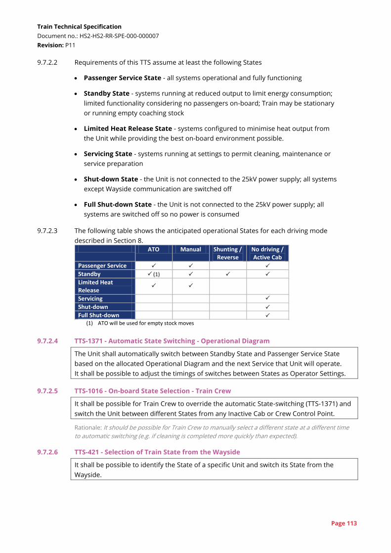
Train Technical Specification
Document no.: HS2-HS2-RR-SPE-000-000007
Revision: P11
Page 113
9.7.2.2 Requirements of this TTS assume at least the following States
Passenger Service State - all systems operational and fully functioning
Standby State - systems running at reduced output to limit energy consumption;
limited functionality considering no passengers on-board; Train may be stationary
or running empty coaching stock
Limited Heat Release State - systems configured to minimise heat output from
the Unit while providing the best on-board environment possible.
Servicing State - systems running at settings to permit cleaning, maintenance or
service preparation
Shut-down State - the Unit is not connected to the 25kV power supply; all systems
except Wayside communication are switched off
Full Shut-down State - the Unit is not connected to the 25kV power supply; all
systems are switched off so no power is consumed
9.7.2.3 The following table shows the anticipated operational States for each driving mode
described in Section 8. ATO Manual Shunting /
Reverse No driving / Active Cab
Passenger Service
Standby (1)
Limited Heat Release
Servicing
Shut-down
Full Shut-down
(1) ATO will be used for empty stock moves
9.7.2.4 TTS-1371 - Automatic State Switching - Operational Diagram
The Unit shall automatically switch between Standby State and Passenger Service State
based on the allocated Operational Diagram and the next Service that Unit will operate.
It shall be possible to adjust the timings of switches between States as Operator Settings.
9.7.2.5 TTS-1016 - On-board State Selection - Train Crew
It shall be possible for Train Crew to override the automatic State-switching (TTS-1371) and
switch the Unit between different States from any Inactive Cab or Crew Control Point.
Rationale: It should be possible for Train Crew to manually select a different state at a different time
to automatic switching (e.g. if cleaning is completed more quickly than expected).
9.7.2.6 TTS-421 - Selection of Train State from the Wayside
It shall be possible to identify the State of a specific Unit and switch its State from the
Wayside.
Train Technical Specification
Document no.: HS2-HS2-RR-SPE-000-000007
Revision: P11
Page 114
9.7.2.7 TTS-1370 - On-board State Selection - Maintenance / Servicing
It shall be possible for cleaners to switch a Unit into Servicing State using a single control
on-board the Unit and without having to log in.
This control shall be inaccessible or inoperable when the Unit is in Passenger Service State.
Rationale: Cleaners will only need access to the Unit, and will not need to control the Unit in any way
except that lighting, Interior Doors etc. should be operational.
9.7.2.8 TTS-2174 - Switch Out of Maintenance State
The Unit shall switch back from Servicing State to Standby State, by activating the control
(TTS-1370) again, or after a defined time period, which shall be an Operator Setting.
9.7.2.9 TTS-840 - Management of Power Supply Interruption - Standby
If a Unit in Standby State loses 25kV power supply whilst stationary, the Unit shall, after a
defined time period, automatically drop its pantograph, switch to Shut-down State and
report this change to the Wayside.
The time period shall be an Operator Setting.
Rationale: Dropping the pantograph saves on-board energy and gives a visual indication to depot
staff that power has been lost.
9.7.2.10 TTS-1602 - Maintain Communication in Shut-down
When in Shut-down State, the Unit shall maintain communication with the Wayside while
auxiliary power is available.
Rationale: This enables the Unit to be remotely switched back on.
9.7.2.11 TTS-2477 - Full Shut-down
When in Shut-down State, the Unit shall switch to a Full Shut-down State at a defined low
battery level.
Rationale: A minimum level of battery capacity and voltage must be protected such that the Unit can
raise its pantograph when 25kV is available.
9.7.2.12 The exact list of driving modes and operational States will be developed by the TMM as
part of the functional integration process described in MSA Schedule 11.
9.7.3 Activation times
9.7.3.1 TTS-428 - Start Up Time from Standby
The Unit shall start-up from standby in no more than 90 seconds. This shall be measured
from the Unit being in Standby State to the Unit being in Passenger Service State and ready
to depart on a service, excluding:
time between request for and receipt of an ETCS MA; and
time to pre-heat / pre-cool the interior.
This shall include a reasonable period for the Train Captain to enter any mandatory data,
unless this is automatically set.
Train Technical Specification
Document no.: HS2-HS2-RR-SPE-000-000007
Revision: P11
Page 115
9.7.3.2 TTS-2735 - Start-up Time from Shut-down
The Unit shall start-up from shut-down in no more than 180 seconds. This shall be
measured from the Unit being in Shut-down State to the Unit being in Passenger Service
State and ready to depart on a Service, excluding:
time between request for and receipt of an ETCS MA; and
time to pre-heat / pre-cool the interior.
The time to charge air-supplies is not included in this time. This start-up time shall include
a reasonable period for the Train Captain to enter any mandatory data, unless this is
automatically set.
Rationale: Although it is envisaged that Units will rarely be in the Shut-down State immediately prior
to a Service, the Unit may be restarted to clear faults (even if this is not the correct course of action to
resolve the fault), and the time taken to restart becomes critical to the length of the delay.
Cross-reference: See also Requirement TTS-2309 (ETCS Power-up Time) in Section 8.3.2 (ETCS
performance)
9.7.3.3 TTS-1373 - Stand-by Time
The Unit shall change from Passenger Service State to Standby State in no more than 30
seconds. This shall be measured from the point that the Unit comes to a halt at the end of
a Service to the point it is in a Standby State with no Train Captain logged in.
9.7.3.4 TTS-2040 - Train Captain Changeover Time
The Unit shall facilitate a changeover of Train Captains (TTS-1606) within a two-minute
Dwell Time. In this time period there shall be time for the exiting Train Captain to:
release and opening doors;
log out of the Cab; and
exit the Cab and Unit.
In this time period there shall be time for the entering Train Captain to:
enter the Unit and Cab;
log in to the Cab;
adjust Cab setting to the Train Captain's personal preferences; and
fulfil the Train Captain's role in closing doors, which does not include checking the PTI.
9.7.4 Train Captain settings
9.7.4.1 TTS-2044 - Train Captain Settings
The Train Captain shall be able to save their settings for all electronically adjustable
systems in the Cab.
The Train Captain shall be able to restore a Cab to these saved settings.
Rationale: Saved settings will prevent Train Captains having to remember their preferred settings and
re-adjust the cab every time they enter a new cab.
9.7.4.2 The following list of systems are envisaged as being part of the saved settings (depending
on the design of these systems):
cab seat position;
Train Technical Specification
Document no.: HS2-HS2-RR-SPE-000-000007
Revision: P11
Page 116
'driver's safety device' footpedal height;
cab radio volume; and
Cab HVAC settings.
9.7.4.3 TTS-2047 - Train Captain Settings - Wayside Synchronisation
When the Train Captain saves their settings, these shall be synchronised with a database of
settings on the Wayside.
Rationale: This functionality should work between different Units.
9.7.4.4 TTS-2048 - Train Captain Settings - Automatic Adjustment
When the Train Captain logs in to a Cab, the Cab shall automatically adjust to their last-
saved settings, as recorded in a database on the Wayside Data System.
Rationale: This reduces the time taken for a Train Captain to get the cab to their liking.
9.8 Interworking and coupling
9.8.1 Interworking and rescue
9.8.1.1 Interworking
9.8.1.1.1 TTS-249 - Interworking Function (PQTS-89) - Mandatory
The Unit shall enable coupling to, and interworking with, another Unit of the same type,
regardless of its orientation.
All functions that are available on a single Unit shall be available on a coupled Train of two
Units.
9.8.1.1.2 There are no requirements for compatibility with rolling stock that may be procured with
later phases of the High Speed 2 Project, other than the rescue requirements in Section
9.8.1.2, below.
Rationale: Achieving interworking between Phase 1 and Phase 2 rolling stock (which may be supplied
by different manufacturers) is considered too complex given the complexity of train control required.
9.8.1.1.3 TTS-1426 - Propelling Mode
A 400m Train shall be able to switch to a propelling mode. In this mode, one Unit lowers its
pantograph while the Train is in motion.
The Unit with the raised pantograph shall supply all tractive effort for the Train.
The Unit with the lowered pantograph shall supply full auxiliary loads regenerated from its
traction system.
Both Units shall provide full functionality and performance (except journey time
performance) as if fully powered.
Rationale: This is a mode that will potentially be used on the CRN if it is not possible to operate with
two pantographs raised at high speeds - see requirements in section 7.5.2. It is assumed that full
auxiliary power could be re-generated from the traction system when the Unit is moving at higher
speed. When stationary or at low speeds, the second Unit would need to raise its pantograph. Note
that the journey time and traction requirements to not apply to this mode.
Train Technical Specification
Document no.: HS2-HS2-RR-SPE-000-000007
Revision: P11
Page 117
9.8.1.1.4 TTS-1590 - Propelling Mode Pantograph Control
When in propelling mode, the Unit not providing tractive effort shall automatically raise its
pantograph at low speed and lower the pantograph as speed increases.
9.8.1.2 Rescue
9.8.1.2.1 The following definitions are made for this section:
Unit - an HS2 conventional-compatible Unit as defined by this TTS;
unit - any unit including a Unit (as above), or another 200m HS2 unit procured in a
later phase or locomotive that a Unit could encounter;
rescuing unit - the unit undertaking the rescue that is fully powered and
operational;
failed unit - the unit that requires rescue and has somehow failed; and
rescue Train - the formation of one or more rescuing Units and one or more failed
Units.
9.8.1.2.2 TTS-820, TTS-432 and TTS-1626 apply to rescue scenarios where one of the units may not
be a 'Unit', as defined by this TTS. TTS-3415 and TTS-3419 only apply to scenarios where
both units are 'Units'.
9.8.1.2.3 TTS-820 - Brake Control when Failed
It shall be possible to control a failed Unit's braking from a rescuing unit via the UIC brake
system (brake pipe as braking control command line).
Rationale: The LOC&PAS TSI[4] requires rescue by a Vehicle equipped with a UIC brake system. This
could be complied with via a simple on/off brake control. Full control provided by the UIC brake
system is required for rescue scenarios. Note that TTS-2612 requires 5 hours' auxiliary supply to
support brake control on the failed Unit.
Cross-reference: See also Requirement TTS-220 (Rescue Performance) in Section 7.2 (Traction)
9.8.1.2.4 TTS-432 - Brake Control when Rescuing
A rescuing Unit shall be able to control a failed unit's braking via the UIC brake system
(brake pipe as braking control command line), provided that the failed unit has a
compatible brake system.
Rationale: This is the equivalent requirement to TTS-820 for the rescuing Unit.
9.8.1.2.5 TTS-3415 - Train Control when Failed
It shall be possible to control the traction of the rescuing Unit and the braking of the rescue
Train from the Cab of the failed Unit, provided that auxiliary power is available on all Units
and there are no faults preventing this.
Rationale: It may only possible to rescue a failed Unit from the rear and not possible to reverse
direction. Therefore, it will be necessary to control the rescue Train from the leading Cab of the failed
Train Technical Specification
Document no.: HS2-HS2-RR-SPE-000-000007
Revision: P11
Page 118
Unit. It is assumed that the failure on the failed Unit does not inhibit this operation. Note that TTS-
2612 requires 5 hours' auxiliary supply to support this operation.
9.8.1.2.6 TTS-1626 - Auxiliary Supply during Rescue
When the rescue Train is in motion, it shall be possible for the failed Unit to provide full
auxiliary power to systems on the failed Unit, generated from the traction system on the
failed Unit, provided the relevant systems are still operational.
Rationale: This will support longer rescue periods and provision of more facilities to Passengers (e.g.
HVAC).
9.8.1.2.7 TTS-3419 - Auxiliary Supply via Jumper
It shall be possible to make a connection between two Units' Auxiliary Power Systems via a
jumper such that the rescuing Unit can supply auxiliary power to the failed Unit. This
jumper will be Special Operator Equipment.
Rationale: This would allow limited transfer of power if a failed Unit lost all stored energy.
9.8.1.3 Rescue couplers
9.8.1.3.1 TTS-375 - Rescue Coupler - Compatibility
The Fleet shall be supplied with rescue couplers and pneumatic hoses for rescue
compatibility with:
units with a Dellner 12 couplers at 1025mm above rail level;
units with a Dellner 12 couplers at 925mm above rail level; and
draw hook.
These rescue couplers will be Special Operator Equipment.
Rationale: This should enable coupling to most rolling stock on the WCML and ECML. Dellner 12 (or
compatible Voith type 136) couplers at 925mm are becoming a UK standard for multiple units.
However, Class 390 and 22x units have a different height and compatibility with these units is also
required. See RSSB research report T1003[109] for more detailed information.
Cross-reference: See also Requirement TTS-1181 (Rescue Coupler Storage) in Section 10.11
(Equipment and storage)
9.8.2 Coupling process
9.8.2.1 Coupling / uncoupling process
9.8.2.1.1 TTS-250 - No Impacts from Coupling / Uncoupling (PQTS-152)
When coupling or uncoupling, Passenger-facing functions of the stationary Unit, including
Exterior Door control, shall be unaffected.
Rationale: Some 400m Trains will need to split and join mid-journey. To minimise the impact on
journey time, the Unit will need to be able undertake normal station operations during this time. It
may be decided, operationally, to close doors during the coupling process, but the Unit design should
not require this.
Train Technical Specification
Document no.: HS2-HS2-RR-SPE-000-000007
Revision: P11
Page 119
9.8.2.1.2 TTS-1627 - Forces during Coupling
When coupling, the maximum jerk and acceleration experienced on either Unit shall be low
enough for Passengers to be able to board and alight the stationary Unit during the
process.
Rationale: This requirement complements TTS-250. As well as being able to functionally couple with
doors open, the motion of the two Units must support Passengers boarding and alighting during the
couple. This may be achieved through energy absorbing couplers or other means.
9.8.2.1.3 TTS-251 - Maximum Couple Time (PQTS-151)
The time to couple two Units shall not exceed 120 seconds. This is measured from the
time when the second Unit contacts and mechanically couples with the stationary Unit until
the combined Train is ready to depart. It includes:
the time to make an electrical connection and re-configure systems into a single
operational Train;
the time for normal dwell activities (e.g. close Exterior Doors), which may overlap coupling
and reconfiguration; and
the time for the combined Train to request an ETCS MA.
Rationale: Achievement of this time is necessary to support the planned train service.
9.8.2.1.4 TTS-252 - Maximum Uncouple Time (PQTS-235)
The time to uncouple two Units shall not exceed 120 seconds. This is measured from when
the two coupled Units come to a stop until one of the Units is ready to depart. It includes:
the time to separate mechanical and electrical connections;
the time to retract couplers and close coupler covers if this must happen while stationary
(see TTS-1624);
the time for both Units to reconfigure into single Units; and
the time for normal dwell activities (e.g. close Exterior Doors), which may overlap coupling
and reconfiguration.
Rationale: The 120 second duration supports completion of uncoupling in a standard station Dwell
Time.
9.8.2.1.5 TTS-1624 - Single Stop Uncoupling (PQTS-235)
When two Units arrive at a station, uncouple and depart, both Units shall come to a stop
only once in the process. The Units shall either:
be able to retract couplers and close coupler covers while stationary; or
be able to close coupler covers while in motion without affecting the acceleration of the
Train.
Rationale: A second stop at the station would lengthen the uncoupling process and confuse
passengers.
9.8.2.1.6 TTS-1735 - Uncoupling from Lead Cab
It shall be possible to uncouple two Units from a Cab remote from the coupling.
Rationale: When a Train splits in a station, the Train Captain in the leading Unit should be able to
uncouple the trailing Unit without leaving the Cab at the front of the formation. It should not be
Train Technical Specification
Document no.: HS2-HS2-RR-SPE-000-000007
Revision: P11
Page 120
necessary to activate either of the Cabs adjacent to the coupler between the two Units in order to
uncouple. This would require extra staff, and creates a risk of delay.
9.8.2.1.7 TTS-2090 - Uncoupling from Centre Cab
It shall be possible to uncouple two Units from only one of the Cabs adjacent to the
coupler.
Rationale: If a 400m Train is split into two Units in a depot or at a terminal station, the Train Captain
or other Authorised Person may be closer to the centre of the Train.
9.8.2.1.8 TTS-434 - Manual Coupling
The Unit shall include controls in the Cab and/or functionality for the Train Captain to
couple and uncouple two Units, including:
controls to enable a slow-speed approach;
controls to open and close coupler covers at either end of the Train Captain's Unit and
deploy / retract the coupler (if required);
equipment to enable a check that the coupler covers on both units are open and couplers
deployed (if required);
engagement of the electrical heads at the Train Captain's discretion; and
controls to enable a pull-away test, if required.
Cross-reference: See also Requirement TTS-596 (FFRF Auto-coupler View) in Section 9.26.2 (FFRF
CCTV)
See also Requirement TTS-3441 (FFRF Short Range View) in Section 9.26.2 (FFRF CCTV)
9.8.2.1.9 TTS-1614 - No Electrical Connection
When coupled, it shall be possible to disengage the electrical connection between Units
while remaining mechanically coupled.
Rationale: This will enable the two Units to switch from an interworking functionality to a rescue /
recovery formation if one Unit has a failure.
9.8.2.2 Automation for coupling
9.8.2.2.1 TTS-3429 - Minimisation of Coupling Steps
The number of inputs, checks and acknowledgements by the Train Captain during the
coupling process shall be minimised.
Rationale: The more complex the coupling process, the greater variation in coupling time will occur,
and the greater chance the Train Captain will make a mistake.
9.8.2.2.2 TTS-3430 - Coupling Speed Limit
During coupling, the Train Captain shall be able to select a speed limit set at a value
suitable for coupling.
Rationale: This will ensure the Unit is travelling at the correct speed for coupling. When combined
with TTS-3429, the goal is a single 'couple' pushbutton controlling approach speed and coupling.
Cross-reference: See also Requirement TTS-2177 (Set Speed Control) in Section 8.7 (Manual driving
(GoA1))
See also Requirement TTS-3428 (Speed Limiter) in Section 8.7 (Manual driving (GoA1))
Train Technical Specification
Document no.: HS2-HS2-RR-SPE-000-000007
Revision: P11
Page 121
9.8.2.2.3 TTS-1620 - Automatic Coupling - Open Cover
Prior to coupling, both the stationary and moving Unit shall automatically open their
coupler covers and deploy their couplers (if necessary) at the locations where the Units will
couple.
Rationale: Automatic coupling should not rely on the Train Captains to remember to prepare their
Units for coupling. The Unit can use the Operational Diagram allocation to identify that it is planned
to couple at a forthcoming station. The stationary Unit can use its Operational Diagram allocation to
open covers close to the time that coupling should occur.
9.8.2.2.4 TTS-2092 - Control Coupler Covers
The Unit shall prevent the Train Captain from attempting to couple to another Unit with the
coupler cover of either Unit closed.
Rationale: The Train Captain may not have visibility of the coupler cover. It is recognised that it may
not be possible to prevent incorrect operation regarding the coupler cover in all scenarios, but the
Unit should automatically manage the covers in normal operation.
9.8.2.2.5 TTS-3439 - Coupler Cover Speed Interlock
The Unit shall be able to prevent the Train Captain driving the Train at more than 50km/h
with the coupler cover open.
It shall be possible to isolate this function.
Rationale: Driving the Train with the coupler cover open will expose the coupler to damage and affect
noise and energy consumption. However, the scenario where a coupler cover fails must be
manageable.
9.8.2.2.6 TTS-1625 - Reconfigure Train Automatically
Following coupling, the two Units shall automatically reconfigure themselves into a single
Train using data from the Operational Diagram allocation. This shall commence when the
two Units have confirmed successful coupling.
Rationale: This will save time of the Train Captain in the stationary Unit waiting for confirmation of
coupling and then re-configuring the Units.
9.8.2.2.7 TTS-436 - Enable Uncoupling - Automatic
When a 400m Train arrives at station where it is due to uncouple, it shall automatically
uncouple and reconfigure the two Units into two Trains, based on the Operational Diagram
allocation.
Rationale: This will save time of waiting for the second Train Captain entering the second Unit,
uncoupling and then reconfiguring their Unit.
9.8.2.2.8 TTS-1622 - Automatic Uncoupling - Close Covers
Following separation after automatic uncoupling, the two Units shall close their coupler
covers and retract couplers (if necessary) automatically and as soon as possible.
Rationale: It is assumed that coupler covers can only close after the Units have moved apart.
Alternatively the couplers could retract so that covers could close while the Units are stationary.
Train Technical Specification
Document no.: HS2-HS2-RR-SPE-000-000007
Revision: P11
Page 122
9.9 Traction control
See also LOC&PAS TSI[4] §4.2.8.2 and GM/RT2111[84]
9.9.1 TTS-939 - Acceleration Limit
It shall be possible to implement acceleration limits on the CRN based on the Location (Line
& Distance) of the Unit.
Rationale: CRN interface - Certain parts of the CRN have an assumed maximum acceleration or
'attainable speed' in the design of their CCS systems. New rolling stock may exceed this assumed
acceleration and therefore not be compatible with existing equipment without operational controls.
Such controls should be implemented automatically.
9.9.2 TTS-1351 - Tractive Effort Limit
It shall be possible to limit the maximum tractive effort by Location (Line & Distance), time
of year and alternatively a temporary Operator Setting from the Wayside.
Rationale: This is to prevent damage to the track where wheelspin frequently occurs. Limits could be
applied during seasons or could be activated from the NICC at times of known low adhesion.
9.9.3 TTS-959 - Traction-Braking Controller Orientation
With reference to LOC&PAS TSI[4] Clauses 4.2.9.1.6 (4) and 7.3.2.19, the orientation of
traction/braking controls shall follow UK conventions:
the ‘tractive effort’ shall increase by drawing the lever towards the Train Captain; and
the ‘braking effort’ shall increase by pushing the lever away from the Train Captain.
Rationale: Clarification of options in LOC&PAS TSI.
Cross-reference: See also Requirement TTS-2139 (Cab Desk and Control Layout) in Section 10.9.1 (Cab
design)
9.9.4 TTS-1444 - Traction Control Gradation for Manual Driving
In manual driving, the Unit shall have continuously variable traction control with a clear
detent for no traction / coasting.
Rationale: Continuously variable control is considered to the best method of control, based on
feedback from fleets where this has been implemented. It is recognised a variable control position
may be encoded into discrete traction demands, while still giving the impression of continuous
variability. The no traction / coast detent will be used when ATO is Engaged.
Cross-reference: See also Requirement TTS-2139 (Cab Desk and Control Layout) in Section 10.9.1 (Cab
design)
9.10 Brake control
See also LOC&PAS TSI[4] §4.2.4 and GM/RT2045[82]
9.10.1 TTS-259 - Holding Brake (PQTS-416)
The Unit shall have a holding brake function that automatically prevents any roll-back when
the Unit comes to a halt or starts moving when the Unit is on a 35 ‰ gradient.
Train Technical Specification
Document no.: HS2-HS2-RR-SPE-000-000007
Revision: P11
Page 123
Rationale: HS2 and CRN interface - This supports the adoption of a 4.2m overhang on the CRN, and
ensures a Unit cannot roll-back after coming to a stop. It is considered important functionality even
with a shorter nose as it is necessary to hold the train when ATO disengages when coming to a stop.
9.10.2 TTS-937 - Regen Isolation
With reference to LOC&PAS TSI[4] Clause 4.2.8.2.3 (2) and GM/RT2111[84] Clause 3.6.1 (c),
isolation of the regenerative brake shall be recorded and reported to the Wayside.
Inappropriate use of this isolation function shall be discouraged.
Rationale: It is important that the regenerative brake is not incorrectly isolated as this would impact
heat generation in tunnels and increase maintenance costs.
9.10.3 TTS-938 - Braking Status Display
The status of the braking system shall be displayed to the Train Captain, considering:
the rate of braking applied by the Train Captain using the controls;
the brake force or deceleration currently being achieved;
split between different braking systems;
isolation of any parts of the braking system, including sanding; and
energy available to braking systems.
Rationale: The Purchaser does not have a firm view of the braking information to be provided to the
Train Captain. However, air pressure gauges and warnings of isolation are unlikely to be sufficient.
In particular feedback to the Train Captain of the applied or achieved brake rate is likely to be
required. This status display will need to be developed via the functional integration process defined
in Schedule 11.
9.10.4 TTS-953 - Brake Control Gradation for Manual Driving
In manual driving, the Unit shall have continuously variable brake application with clear
detents for emergency brake and coast / no braking.
Rationale: The seven-step brake application is as specified by the LOC&PAS TSI[4]. A continuously
variable brake application has been considered compliant with the LOC&PAS TSI on other projects.
The emergency brake position should be distinguishable from service braking. The no-braking 'coast'
will be used in when ATO is Engaged.
Cross-reference: See also Requirement TTS-2139 (Cab Desk and Control Layout) in Section 10.9.1 (Cab
design)
9.10.5 TTS-2176 - Emergency Brake Control
With reference to LOC&PAS TSI[4] Clause 4.2.4.4.1 (2), at least one of the independent
emergency brake command devices shall be available in an inactive cab (i.e. it can be used
in a rear or middle cab of a Train).
Rationale: UK convention is that the emergency stop plunger / pushbutton in all cabs can be used at
all times.
9.10.6 TTS-926 - Brake Release for Recovery
It shall be possible to release holding and parking brake applications in any vehicle
condition with the Unit at a HS2 Platform or CRN platform. This may be achieved by
coupling another Unit to provide air supply.
Train Technical Specification
Document no.: HS2-HS2-RR-SPE-000-000007
Revision: P11
Page 124
Rationale: It must be possible to recover a stalled Unit, considering all possible conditions for that
unit, including loss of air supply. With reference to releasing the brakes, a Unit located at a platform
is considered the worst location due to the restricted access to the underframe, which may require
internal isolation cocks.
9.10.7 TTS-927 - Parking Brake Automatic Application
With reference to LOC&PAS TSI[4] Section 4.2.4.4, the parking brake shall automatically be
applied following a loss of main braking energy (e.g. main reservoir pressure) such that the
Unit does not move during the transition.
Rationale: HS2 requires an automatic parking brake function as envisaged, but not mandated in
LOC&PAS TSI Section 4.2.4.4.5.
9.10.8 TTS-2039 - Report WSP
Activation of the wheel slide protection system shall be immediately reported to the
Wayside, with details of:
the Train Location (Line & Distance);
the direction of travel;
whether the ATO On-board is Engaged (EG) or not; and
the level of traction or braking demand when spin or slide was detected.
Rationale: This will support collation of data about sites with low adhesion so that preventative
measures can be taken - e.g. more defensive driving.
9.10.9 TTS-3144 - Report WSP in Automatic Mode
When ATO On-board is in Engaged (EG) state, activation of the wheel slide protection
system, together with the currently-applied ATO brake and acceleration rates, shall be sent
by the ATO On-board to the ATO Trackside within 5 seconds.
Rationale: This requirement expands on ATO over ETCS SRS[19] Clause 7.6.1.2 by additionally requiring
brake and acceleration rates. Such information is commonly used in other ATO systems to inform
the required response.
9.11 Jerk rate
9.11.1 TTS-409 - Jerk Rate and Adjustment
The Unit shall control the longitudinal jerk rate to not exceed 0.5m/s³ with the following
exceptions:
loss or substantial instantaneous reduction of traction power supply for any unplanned
reason (i.e. excluding neutral sections);
during the loss of regenerative braking for any irregular reason; and
during the application of the emergency brake.
Rationale: Maintaining an acceptable jerk rate is important to Passenger comfort.
9.11.2 TTS-410 - Jerk Rate Adjustment
It shall be possible to adjust the jerk rate limit between 0.25m/s³ and 0.75m/s³ via a
Software Update.

Train Technical Specification
Document no.: HS2-HS2-RR-SPE-000-000007
Revision: P11
Page 125
Rationale: This requirement is to allow the flexibility to change jerk rate at a later date, if required.
Compliance with journey time, acceleration and energy consumption requirements is only required
with a 0.5m/s³ jerk rate.
9.12 Sanding and adhesion control
See also GM/RT2461[93]
9.12.1 TTS-824 - Sanding Equipment - Mandatory
The Unit shall have sanding equipment for use in traction and braking during low adhesion
conditions.
Rationale: CRN interface - The TSIs and NNTRs cover the performance and functionality of sanding
equipment, but not the need for sanding. A sanding system is necessary for compatibility with the
CRN and may be required for operation on the HS2 Network.
9.12.2 TTS-946 - Automatic Sanding Activation
When On-board ATO is Engaged (EG), sanding shall be automatic in both traction and
braking.
9.12.3 TTS-947 - Automatic Sanding Activation (Braking)
When the Train is being manually driven, sanding shall be automatic in braking.
9.12.4 TTS-948 - Manual Traction Sanding Activation
When the Train is being manually driven, sanding in traction shall be manually activated by
the Train Captain.
The Train Captain shall receive an indication that wheel spin has occurred and shall then be
able to select whether to actuate sanding.
9.12.5 TTS-940 - Automatic Sanding Variation and Inhibition
It shall be possible, in braking and traction, to inhibit or vary the rate of sanding based on
the Unit's Location (Line & Distance).
Variable sanding shall have at least two rates available.
Rationale: Inhibition of sanding will prevent sand being deposited in tunnels or over switches and
crossings. Variability of sanding rates will allow usage of sand to be optimised. It will also permit
different sanding rates for the CRN and HS2 Network. Whereas the CRN has often suffered from low
adhesion, the HS2 Infrastructure Manager intends to manage the HS2 Network to minimise low
adhesion, and would like to minimise contamination of the railway with sand as far as possible.
9.12.6 TTS-2178 - Sand Usage Monitoring
The Unit shall monitor the estimated usage of sand and alert the Wayside when sand is
likely to need to be topped up.
Rationale: Incidents have occurred in the UK where trains have operated without sufficient sand.
This requirement mitigates the risk of this happening, by triggering an Event for the need for more
sand.
Train Technical Specification
Document no.: HS2-HS2-RR-SPE-000-000007
Revision: P11
Page 126
9.12.7 TTS-1700 - Sand Level Monitoring
The Unit shall monitor the level of sand on the Unit and alert the Train Captain and the
Wayside when sand is below a defined level.
Rationale: This requirement, together with TTS-1701 provides a 'last resort' in case sand is not topped
up in response to TTS-2178.
9.12.8 TTS-1701 - Limit Sanding in Low Sand Level
The Unit shall restrict sanding to either braking only or emergency braking only,
configurable as a Software Update, when the sand level is below the defined level specified
in TTS-1700.
9.13 Power supply control
See also LOC&PAS TSI[4] §4.2.8.2 and GM/RT2111[84]
9.13.1 TTS-1489 - Power Supply Transition Trigger
With reference to LOC&PAS TSI[4] Section 4.2.8.2.9.8, the Unit shall automatically transition
through neutral sections and the HS2-CRN transition:
on the HS2 Network, on which ETCS will be installed; and
on the CRN, where ETCS is not currently installed, but Eurobalises are installed for this
purpose.
Rationale: On the HS2 Network, power supply commands will be received via ETCS as envisaged in
the TSIs. On the CRN, HS2 Ltd intends to install Eurobalises to provide instructions for neutral
sections and for the CRN-HS2 transition. The Unit will need to receive messages from the Eurobalises
when operating in Level NTC.
9.13.2 TTS-393 - Neutral Section Transition
With reference to LOC&PAS TSI[4] Clauses 4.2.8.2.9.8 (4) and (5), the Unit shall automatically
remove and restore traction demand such that jerk limits are met.
Rationale: This expands the TSI by requiring traction to be removed in a controlled way.
Cross-reference: See also Requirement TTS-409 (Jerk Rate and Adjustment) in Section 9.11 (Jerk rate)
9.13.3 TTS-1500 - APC Magnet
The Unit shall be capable of being fitted with equipment to enable compatibility with
automatic power control magnets for neutral section transitions on the CRN, in compliance
with GM/RT2111[84] Section 4.11.
Rationale: CRN interface - This is a fall-back option for compatibility with the CRN. HS2 Ltd is seeking
to implement Eurobalises for power supply transitions on the CRN, but it may not be possible to
achieve this.
9.13.4 Non-fitment of an automatic power control receiver would require a deviation to
GM/RT2111 Section 4.11. This would be supported by the Purchaser.
Train Technical Specification
Document no.: HS2-HS2-RR-SPE-000-000007
Revision: P11
Page 127
9.13.5 TTS-256 - HS2-CRN Power Supply Transition (PQTS-194)
The Unit shall transition between the HS2 Network power supply and the CRN power
supply, and vice versa, without any interaction from the Train Captain and without the
Train needing to stop. This shall include:
automatically removing and restoring traction demand such that jerk limits are met;
automatically lowering and raising the HS2 Pantograph and CRN Pantograph (if required);
and
adjusting power supply compatibility limits.
Rationale: Trains should be able to move between the CRN and HS2 networks seamlessly and reliably
to ensure trains run on time. It is expected that two different types of pantograph would be
required, but if a single pantograph can be provided it can retain contact with the OCS/OLE.
Cross-reference: See also Requirement TTS-409 (Jerk Rate and Adjustment) in Section 9.11 (Jerk rate)
9.13.6 TTS-257 - Variable Current Limit (PQTS-229)
The maximum line current drawn by the Unit shall be capable of being automatically varied
due to:
the Location (Network) and Location (Line & Distance) of the Unit;
messages received from Eurobalises compliant with RIS-0784-CCS[80];
whether the Unit is operating as a 200m Train or 400m Train; and
whether the other Unit in a 400m Train has its pantograph raised.
These current limits for different locations / conditions shall be adjustable as a Software
Update.
Rationale: HS2 and CRN interface - As a minimum, the Units will operate with separate current limits
for the HS2 Network and the CRN. Studies are being undertaken to further optimise allowable train
current limits on both the HS2 Network and CRN. This could include varying current limit at different
locations on the networks.
It is currently anticipated that a 300A limit will apply to all operation on the CRN at the introduction of
the Units, but could later be increased. At the moment, the 300A limit applies to the whole train, so a
two-Unit train would be at 150A / Unit.
Cross-reference: See also Requirement TTS-1426 (Propelling Mode) in Section 9.8.1.1 (Interworking)
9.13.7 TTS-1490 - Dynamic Current Limit (PQTS-229)
The maximum line current drawn by a Unit shall be capable of being adjusted temporarily
from the Wayside, for all or part of the Fleet, as an Operator Setting. On the HS2 Network
the current limit will be set using ETCS track condition data sent via balise or data radio.
Rationale: In considering how to optimise the allowable train current and managed service
perturbations, altering current limits in particular scenarios is being considered, for either the whole
fleet or certain units.
9.13.8 TTS-1003 - Dynamic Regenerative Current Limit
The maximum current returned from the Unit during regenerative braking shall be capable
of being adjusted, independently from current drawn in traction:
due to the Location (Line & Distance) of the Unit (as per TTS-257);
due to messages received from Eurobalises (as per TTS-257); and
Train Technical Specification
Document no.: HS2-HS2-RR-SPE-000-000007
Revision: P11
Page 128
as a temporary Operator Setting (as per TTS-1490).
This adjustment shall have no impact on the achieved brake rate.
9.13.9 TTS-3405 - Maximum Regen Voltage
With reference to GM/RT2111[84] Clause 3.6.1.c, while the Train is operating on the CRN,
regeneration shall not be initiated or continue when the OLE voltage at the pantograph is
above a predetermined value within the range of 27kV to 29 kV.
This setting shall be selectable in a maximum of 500V steps.
The setting shall be capable of being varied automatically based on the Location (Line &
Distance) of the Train.
Rationale: CRN interface - Network Rail have advised that a maximum limit of 27kV must be adhered
to where Class 92 locomotives operate - currently the WCML. This is 500V below the limit set in
GM/RT2111.
9.13.10 TTS-814 - MCB Re-close Strategy
Following an unplanned power supply outage individual Units shall automatically close
main circuit breakers at different times such that two Units in the Fleet will not re-close
their main circuit breakers within 20ms of each other within a single electrical section.
Rationale: CRN interface - This function is to manage the loading on the power supply.
9.13.11 TTS-2478 - Shore Supply Interlock
It shall not be possible for a Unit to be moved while it is connected to any shore supply.
9.14 Energy metering
See also LOC&PAS TSI[4] §4.2.8.2.8 and GM/RT2132[87]
9.14.1 TTS-828 - Energy Metering System - Mandatory
The Unit shall include an Energy Metering System.
Rationale: These requirements for an energy metering system are specified to deliver energy data to
the Train Operator. Requirements are set about how the data is recorded to enable potential future
analysis of this data.
9.14.2 TTS-829 - Energy Metering - Traction / Regen / Auxiliary
The Energy Metering System shall record energy separately for:
traction, including any energy for cooling of traction;
regenerated energy; and
non-traction auxiliary loads.
9.14.3 TTS-3188 - Energy Metering - Depot
The Energy Metering System shall record energy separately for when the Unit is in
Washwood Heath depot or any other depot.
Rationale: This enables energy usage during stabling and maintenance to be separately calculated,
which leads to incentivisation to minimise energy consumption when stabled.
Train Technical Specification
Document no.: HS2-HS2-RR-SPE-000-000007
Revision: P11
Page 129
9.14.4 TTS-2034 - Energy Metering Data Processing
The Energy Metering System shall enable energy usage to be recorded in configurable
blocks of time or distance. For each block, the following shall be recorded:
energy consumed (as per TTS-829);
start time and start Location (Line & Distance);
end time and end Location (Line & Distance); and
other on-board data that could affect energy consumption (e.g. payload).
It shall be possible to adjust, as an Operator Setting, whether blocks are time-based or
location-based, and what the start and finish points are in each case.
Rationale: This functionality is to provide data at a level of granularity to allow energy to be summed
for each network, in and out of passenger service, or for other comparative analysis. The
configurable blocks would be set to initial values (e.g. HS2 Network and CRN), but could later be
adjusted if more detailed information is required. Alternatively energy could be recorded in different
time periods to align with different energy prices.
9.15 Pantograph control
9.15.1 TTS-406 - Actions on ADD
Activation of a CRN Pantograph ADD or HS2 Pantograph ADD shall:
be reported to the Train Captain;
provide Pantograph CCTV images from a defined period of time before the ADD
activated;
provide Pantograph CCTV images of the affected pantograph in the stowed position to
the Train Captain; and
be reported to Wayside with location and speed data.
Rationale: Images from before the ADD may allow the Train Captain to see the cause of the ADD
activation. Images of the stowed pantograph are necessary to inspect the pantograph following an
ADD activation, to determine if the pantograph should be re-raised.
9.15.2 TTS-1048 - Reset & Isolate ADD
It shall be possible to isolate an ADD from within the Unit.
Isolation of an ADD shall be recorded, indicated to the Train Captain and communicated to
the Wayside.
Rationale: It should not be necessary to leave the vehicle or access the roof to isolate the ADD.
9.15.3 TTS-1639 - Lower Pantograph to Reduce Noise
It shall be possible to automatically lower and raise the Train's pantograph(s) at defined
Locations (Line & Distance) at any speed up to 360km/h.
It shall be possible to change the locations for lowering and raising the pantographs as a
Software Update.
Rationale: This is required as a potential mitigation of excessive noise in particular locations, in
addition to the acoustic requirements in section 7.18. If the overall noise of the railway cannot be
mitigated by other means, pantographs may be lowered. Journey times would be adjusted
accordingly. Auxiliary power may be regenerated by the traction system or supplied by on-board
batteries.
Train Technical Specification
Document no.: HS2-HS2-RR-SPE-000-000007
Revision: P11
Page 130
9.15.4 TTS-3189 - Switch Pantographs during Wash
The Unit shall automatically switch pantographs when it is traversing a train-wash.
Rationale: The train wash at the Washwood Heath depot should wash as high up the bodyside as
possible, and the pantograph will need to be lowered as the Unit passes through the wash.
9.15.5 The method of train control through the train-wash at Washwood Heath depot is not yet
finalised. Trains could be under ATO or manual control.
Cross-reference: See also Requirement TTS-2177 (Set Speed Control) in Section 8.7 (Manual driving
(GoA1))
9.16 Running Gear monitoring
9.16.1 TTS-2622 - Running Gear Hunting Detection
The Running Gear shall be monitored for vibrations indicative of hunting.
If hunting is detected, the Train shall make an automatic service brake application until
hunting has stopped.
The Train Captain and the Wayside shall be informed that hunting has been detected.
Rationale: Hunting has been witnessed on other rolling stock designed to operate on two different
networks.
9.16.2 TTS-2623 - Running Gear Derailment Detection
The Running Gear shall be monitored for indications that it has derailed.
If derailment is detected, the Train shall automatically make an emergency brake
application to stop the Train.
The Train Captain and the Wayside shall immediately be informed that derailment has
been detected.
Rationale: This function helps to mitigate hazards associated with derailments. There have been
incidents where derailment has not been reacted to quickly enough.
9.16.3 TTS-3184 - Deflated Suspension Monitoring
If there are any operational limitations on the Train when the secondary suspension is
deflated:
the Train Captain shall be informed of the deflation; and
any necessary speed restriction shall be automatically implemented with removal of
traction and a service brake application if the Train is travelling above the speed restriction.
Rationale: Deflated suspension is a rare occurrence and hence design for full performance in this
condition may lead to over-design of systems. Limitations in deflated condition are permissible, but
need to be managed as part of operation of the Train.
9.17 Payload management
9.17.1 TTS-1582 - Payload Information
The Train Captain, Train Crew and the Wayside shall be able to view
the measured payload of each Vehicle in the Train;
whether a Vehicle is exceeding the Exceptional Payload (HDL); and
Train Technical Specification
Document no.: HS2-HS2-RR-SPE-000-000007
Revision: P11
Page 131
a time history of the Payload information.
Rationale: This information allows operational staff to understand the loading of the Unit, and take
decisions about operation of the Unit.
9.18 Exterior Doors
See also LOC&PAS TSI[4] §4.2.5.5.
9.18.0.1 The requirements of this section apply to all Exterior Doors - i.e. all doors between the
inside of the Unit and the exterior except for dedicated Cab Doors (if provided). Doors may
be configured as crew-only doors (see TTS-2928), but all Exterior Doors must be capable of
meeting the requirements of this section.
9.18.1 Standards
9.18.1.1 TTS-1276 - Compliance with EN 14752
All Exterior Doors and Moveable Steps shall be compliant with the requirements of EN
14752[40] except where clarified or superseded by the requirements of this specification.
Rationale: HS2 considers this standard to provide good practice requirements. Where necessary,
clarifications are made through TTS requirements in this section and section 7.15.
9.18.2 Train-wide door control
9.18.2.1 For each station on the CRN and HS2 Network there will be a 'door control strategy', i.e. an
approach to releasing, opening and closing the doors at the station and who is responsible
for each step. This section lists requirements to enable each of these strategies.
9.18.2.2 TTS-1232 - Configuration of Door Control Strategies
It shall be possible, as an Operator Setting, to configure a door control strategy for each
station based on the time of day, including:
how a door release command will be given to the Train and by whom;
how Exterior Doors will be opened and by whom;
whether auto-close time (TTS-307) differs from its default value or is inhibited;
how the PTI will be checked and by whom; and
how a Train-wide door close command is given and by whom.
Rationale: The door control mode may need to be changed based on the station and the time of day
to reflect the expected passenger flows and other considerations such as noise experienced by
neighbours or control of heat exchange with external air.
9.18.2.3 TTS-1281 - Display of Door Control Strategy to Train Captain
The door control strategy for the next / current station (TTS-1232) shall be displayed to the
Train Captain and at the Crew Control Point on approach to the station and during the
station stop.
Rationale: The Train Captain should be made aware of the planned door control strategy to reduce
the chances of errors on arrival at a station. This should allow the Train Captain to understand who
has responsibility for releasing, opening and closing doors at the next station.

Train Technical Specification
Document no.: HS2-HS2-RR-SPE-000-000007
Revision: P11
Page 132
9.18.2.4 The door control strategy may be made up of a combination of the following requirements.
9.18.2.5 TTS-315 - Train Captain Door Control
The Exterior Doors and Moveable Steps shall allow control by the Train Captain including
the following operations:
Train Captain commanded release and open of all available doors and steps on one side
of the Train;
Train Captain commanded release of all available doors and steps on one side of the
Train, to allow Passengers to open individual doors using the local door pushbuttons; and
Train Captain commanded close of all doors (when it has been confirmed to the Train
Captain that it is safe to close doors).
Rationale: These door control modes are required to support the HS2 Operational Concept. Note
there is no requirement for the Train Captain to be able to assess the PTI from Cab e.g. via on-board
cameras.
9.18.2.6 TTS-318 - Automatic Door Control
The Train shall enable the following automatic operations without input from the Train
Captain:
automatic release and open of all available Exterior Doors and Moveable Steps on one
side of the Train, when the Train stops at a station; and
automatic release of all available Exterior Doors and Moveable Steps on one side of the
Train when the Train stops at a station, to allow Passengers to open individual doors using
the local door pushbuttons.
The Train Captain shall be able override automatic operations.
Rationale: These door control modes are required to support the HS2 Operational Concept. Note
that when the Unit is being driven by ATO On-board, these are not the only door control strategies.
Train Captain or Train Crew control of doors may be used with ATO On-board just controlling driving.
9.18.2.7 TTS-2828 - Automatic Door Release and Accuracy
During automatic door operation (TTS-318) door release shall only be requested when the
Train has confirmed it has stopped within the required stopping accuracy (TTS-100).
Cross-reference: See also Requirement TTS-100 (ATO Stopping Accuracy) in Section 8.6.4 (ATO
stopping accuracy)
9.18.2.8 TTS-316 - Train Crew Door Control
The Exterior Doors and Moveable Steps shall allow control by the Train Crew from a door
control point or an Inactive Cab, including the following operations:
Train Crew commanded release and open of all available doors and steps on one side of
the Train;
Train Crew commanded release of all available doors and steps on one side of the Train,
to allow Passengers to open individual doors using the local door pushbuttons;
Train Crew commanded close of all doors and steps on the Train; and
Train Crew commanded close of the doors and steps of the Unit where the Train Crew is
located.
Train Technical Specification
Document no.: HS2-HS2-RR-SPE-000-000007
Revision: P11
Page 133
Rationale: These door control modes are required to support the HS2 Operational Concept. For
400m Trains, if Train Crew are responsible for checking the PTI and closing doors it is considered that
two Train Crew may be required, each taking responsibility for a Unit. This could vary between
stations depending on the characteristics of the platform.
9.18.2.9 TTS-302 - Pre-arm Doors
When the door control strategy for the next station (TTS-1232) indicates that Exterior Doors
are to be opened by Passengers using local door pushbuttons, pressing a local door open
pushbutton up to 60 seconds before a door release command is received shall cause the
Exterior Door to open as soon as they are released (and the Moveable Step is deployed).
If the pushbutton is being held at the point when the door release command is received
the Exterior Door shall still open without the pushbutton needing to be released and
pressed again.
Rationale: This is intended to both reduce confusion for Passengers and also to ensure doors are
opened as quickly as possible when under Passenger control. On arrival at stations, the time taken
for the deployment of the Moveable Step may create confusion and frustration for Passengers trying
to open the doors.
9.18.2.10 TTS-312 - Evacuation Door Control
The Unit shall enable both the Train Captain and the Train Crew to release any subset of
Exterior Doors in the Train while all other Exterior Doors remain closed and locked and
temporarily unresponsive to Emergency Egress Devices.
It shall be possible to implement this function from both a Cab and the Crew Control Point.
Rationale: This is to support the tunnel evacuation strategy. Ideally, the ATO On-board will stop
Trains with the designated Evacuation Door adjacent to a cross-passage. Passengers need to be
managed to only evacuate through the specified door. In some scenarios, it may be necessary to
evacuate through another Exterior Door instead of the designated Evacuation Doors. It is recognised
that this function could be deemed non-compliant to the LOC&PAS TSI[4] Clause 4.2.5.5.9 (1), but this
functionality is required, subject to agreement of the evacuation process. A safety analysis will be
required to show that the Exteriors Doors cannot fail in a locked-out condition.
Cross-reference: See also Requirement TTS-165 (Evacuation Door Position) in Section 7.15.7
(Evacuation)
See also Requirement TTS-2035 (Temporary Isolation of Emergency Open Device) in Section 9.18.8
(Emergency Egress Device)
9.18.2.11 TTS-314 - Terminal Station Mode
The Train shall have a terminal station door control mode that leaves Exterior Doors
released but closed, and prevents Exterior Doors from being operated by local external
controls.
In this mode:
the Moveable Step shall remain deployed;
internal pushbuttons for Exterior Doors shall remain active; and
Exterior Doors shall be closed by auto-close functionality or local door pushbuttons.
Rationale: This function is intended to support railway operations at terminal stations where Trains
may be prepared to turn around or prepared for an empty stock move.
Train Technical Specification
Document no.: HS2-HS2-RR-SPE-000-000007
Revision: P11
Page 134
9.18.2.12 TTS-1294 - Authorised Access in Terminal Station Mode
A means shall be provided, at each Exterior Doorway, to allow Authorised Persons to
access the Unit when the Unit is in terminal station mode (TTS-314).
Rationale: This function is required to allow staff to access catering facilities whilst Units are at
stations in order to carry out tasks such as re-stocking. It should be possible to ensure the Units is
still secured from unauthorised access.
9.18.2.13 TTS-2835 - Door Release in Standby
It shall be possible for the Unit to retain an active door release command while the Unit is
in Standby State.
In this mode, external door pushbuttons shall not be active as per the terminal station
mode (TTS-314).
Rationale: When Units are between services or stabled, it will be necessary to provide access for
servicing and maintenance. For access, the Moveable Steps will need to be deployed; it is expected
that this means the doors must be released.
9.18.2.14 TTS-317 - Selective Re-open Control
Following a Train-wide door close command it shall be possible to fully re-open and re-
close only those doors not proved closed.
Rationale: This functionality is required to allow issues at stations to be resolved as quickly as
possible to facilitate HS2's Dwell Time aspirations.
9.18.2.15 TTS-1437 - Selective Door Inhibit
The Unit shall include functionality to allow individual doors to be inhibited from opening at
specific stations based on commands from the Train Captain or from the Wayside.
Rationale: This functionality is intended to allow for resolution of incidents in service where station
operations require certain doors not to open. This is in addition to the selective door operation
functionality.
9.18.2.16 TTS-1438 - Selective Door Inhibit PIS Interface
The PIS shall be capable of automatically providing audio or visual information to
Passengers related to the operation of the selective door inhibit functionality (TTS-1437).
The messages shall be broadcast in the affected Vestibule and any adjacent Saloons.
Rationale: Passengers should be made aware of situations where doors will not be opened at the
next station.
9.18.3 Automatic Selective Door Operation (ASDO)
9.18.3.1 TTS-313 - Automatic Selective Door Operation (ASDO) - Mandatory
The Unit shall be provided with an ASDO system / function that:
is operable on both the HS2 Network and the CRN; and
only permits Exterior Doors and Moveable Steps adjacent to a platform to be released
and opened.
Rationale: ASDO is required to allow Trains to stop at stations with different platform lengths.
Train Technical Specification
Document no.: HS2-HS2-RR-SPE-000-000007
Revision: P11
Page 135
9.18.3.2 The ASDO only needs to work with Eurobalises (as required by TTS-3028) for both the HS2
Network and CRN. Alternative methods of defining the Train's location (e.g. GNSS, other
proprietary beacon systems) are not required.
9.18.3.3 TTS-3028 - ASDO Eurobalise Message
The ASDO system shall be capable of controlling Exterior Door and Moveable Step release
in accordance with:
CCS TSI[5] when operating under ETCS; and
messages received from Eurobalises compliant with RIS-0784-CCS[80].
9.18.3.4 TTS-1609 - Correct Side Door Enable (CSDE) Functionality
The ASDO shall include Correct Side Door Enable (CSDE) functionality on both the HS2
Network (via ETCS) and CRN (via Eurobalise).
CSDE functionality shall only permit Exterior Doors and Moveable Steps to be released on
the side of the Train adjacent to a platform.
Rationale: This system is intended to improve safety by ensuring only the doors on the correct side of
the train can be released.
9.18.3.5 TTS-1610 - Correct Stopping Position
When the Train has been manually stopped at a station (i.e. the ATO On-board has not
controlled the stopping), the ASDO shall ensure the Train is at the correct stopping position
before permitting Exterior Doors and Moveable Steps to be released.
Rationale: This system is intended to improve safety by ensuring that the door release pattern is
correct for the stopping location.
Cross-reference: See also Requirement TTS-2828 (Automatic Door Release and Accuracy) in Section
9.18.2 (Train-wide door control)
9.18.3.6 TTS-1223 - ASDO Function during Train State Change
The ASDO system shall remain effective in inhibiting the appropriate doors even when the
Train:
changes State;
changes direction (e.g. at a terminus); and
is coupled to or uncoupled from another Unit.
Rationale: This functionality is intended to eliminate a risk that a Unit is activated and doors not
adjacent to a platform can be released.
Cross-reference: See also Section 9.7.2 (Operational states)
9.18.3.7 TTS-2933 - ASDO on Shut-down
If restarting the Unit clears ASDO information, only the Train Captain shall be able to
release Exterior Doors and Moveable Steps, and the Train Captain shall be provided with a
warning that ASDO is not active prior to release of doors and steps.
Rationale: Restarting the Train should not allow the Train Captain or Train Crew to accidentally
release more doors that were previously permitted by the ASDO. Only the Train Captain can
establish the position of the Unit.
Train Technical Specification
Document no.: HS2-HS2-RR-SPE-000-000007
Revision: P11
Page 136
9.18.3.8 TTS-1303 - ASDO Override
The Train Captain shall be able to override the ASDO and CSDE system and select which
Exterior Doors and Moveable Steps will be released or inhibited.
This override shall be recorded and shall be communicated to the Wayside.
Rationale: The Train Captain should be able to manually override the ASDO system on a Train, Unit,
Vehicle or Exterior Door basis for situations such as emergency evacuation, ASDO system failure,
normal stopping point not available, etc. This function is only available to the Train Captain as only
the Train Captain can establish the position of the Unit.
9.18.4 Exterior Door system
9.18.4.1 TTS-3272 - Vehicle Overturning Load Case
With reference to EN 14752[40] Clause 4.2.1.4, Exterior Doors shall be assessed for the
optional vehicle overturning load case.
Rationale: This requirement provides clarification that compliance with this optional requirement
should be provided.
9.18.4.2 TTS-3285 - Emergency Access Device Colour
With reference to EN 14752[40] Clause 4.3.3.3, emergency access devices shall be the same
colour as the surrounding area in which they are mounted, and not red (RAL 3020) as
recommended in Clause 4.3.3.3.
Rationale: This requirement provides clarification that ensures consistency with common practice in
the UK to minimise misuse of the access devices.
9.18.4.3 TTS-3286 - Local Door Controls - Door Open Control Availability
The local Exterior Door open pushbuttons shall be deactivated, including removal of any
illumination, when a Train-wide door close command is initiated and remain deactivated
throughout the door closing process.
Rationale: This requirement is included for clarity and as a result of learning point 4 in the RAIB
report on West Wickham.
9.18.4.4 TTS-303 - Local Door Controls - Door Close
All Exterior Doors shall be provided with internal door close pushbuttons compliant with
EN 14752[40] Section 4.3.
Rationale: This permits Passengers and Train Crew to close doors to manage internal climate.
9.18.4.5 TTS-1271 - Door Out-of-Service Indicator
In addition to the requirements of EN 14752[40] Section 4.3 a separate door out-of-service
indication shall be provided internally and externally at all Exterior Doors.
Rationale: It is considered that a clear separate indicator should be provided to Passengers over and
above indication on the door open/close buttons. This could be on the door or adjacent to controls.
Train Technical Specification
Document no.: HS2-HS2-RR-SPE-000-000007
Revision: P11
Page 137
9.18.4.6 TTS-1272 - Door Closing Force
The closing force of all Exterior Doors shall be compliant with force level (1) in EN 14752[40]
Clause 5.2.1.4.2.2.
Rationale: It is considered that the higher force level is not applicable.
9.18.4.7 TTS-1273 - Door Closing Kinetic Energy
The kinetic energy contained by Exterior Doors throughout their travel on closing shall not
exceed 20 J when calculated according to EN 14752[40] Clause 5.2.1.4.2.3.
Rationale: It is considered that the kinetic energy of the Exterior Doors should be limited to minimise
the risk of injury to Passengers.
9.18.4.8 TTS-304 - Door Audible Warnings
The timings of audible alerts for operation of Exterior Doors shall be adjustable as a
Software Update.
Rationale: The HS2 Train Operator will want to retain the ability to optimise the timings of door
operations whilst still complying with the requirements of the PRM TSI.
9.18.4.9 TTS-2928 - Crew-only Door
It shall be possible to configure any Exterior Door as a Train Crew-only door via a Software
Update.
When configured in this way,
it shall only be controllable by Authorised Persons and auto-close shall be inhibited; and
all pushbuttons for Passengers shall not illuminate.
Rationale: This is a change that would be made during reconfiguration or refurbishment. The door
may be repainted so as not to contrast with the bodyside so it is clearly not a door for Passengers.
9.18.5 Auto-close Cross-reference: See also Requirement TTS-3267 (Call For Aid Exterior Doorway) in Section 9.24.2 (Call
For Aid)
9.18.5.1 TTS-307 - Door Auto-close
Exterior Doors shall automatically close after a defined amount of time.
The amount of time shall be an Operator Setting.
Rationale: Doors should close automatically after a fixed period of time to limit ingress of cold air or
rain water.
Cross-reference: See also Requirement TTS-1654 (Moveable Step Retraction) in Section 9.18.9
(Moveable Step)
9.18.5.2 TTS-1283 - Door Auto-close Inhibit during Boarding/Alighting
The auto-close command shall not close the Exterior Door while Passengers are boarding
or alighting through that doorway, or if Passengers are partially obstructing the doorway.
Detection of Passengers boarding or alighting shall reset the auto-close timer.
Rationale: If a Passenger passes through the door it should not close or not continue to close as part
of the auto-close function. Passengers may attempt to cancel auto-close by placing their arm or leg
Train Technical Specification
Document no.: HS2-HS2-RR-SPE-000-000007
Revision: P11
Page 138
in the doorway expecting this to stop the motion of the door. The auto-close detection should pick
up the widest range of obstructions.
9.18.5.3 TTS-1651 - Local Auto-close Inhibit
It shall be possible for Train Crew or the Train Captain to inhibit auto-close at a particular
Exterior Door for the remainder of a station stop.
It shall be possible to activate this command local to the Exterior Door, or from a Cab or
Crew Control Point.
Rationale: It should be possible for staff to locally inhibit the auto-close function to allow the use of
equipment such as manual On-board Ramps. This function may be combined with controls of the
Moveable Step at the same doorway (TTS-1640). Unlike retracting the step, this function does not
affect safety, so achieving this function using existing controls (e.g. holding the 'open' pushbutton for
two seconds) would be suitable.
Cross-reference: See also Requirement TTS-1640 (Retract Step) in Section 9.18.9 (Moveable Step)
9.18.5.4 TTS-1302 - Door Controls During Auto-close
During or following auto-close of Exterior Doors the local door open pushbuttons shall
remain active.
Activating a control shall cause the Exterior Door to re-open.
Rationale: Passengers should be able to stop the doors from closing or re-open the doors as long as a
close command has not been received.
9.18.6 Door obstacle detection See also LOC&PAS TSI[4] §4.2.5.5.3 (5)
9.18.6.1 TTS-306 - Obstacle Management
The Exterior Door obstacle detection sequence shall allow the following parameters to be
adjusted as Software Updates:
door re-opening distance;
number of obstacle detections prior to complete door re-open; and
triggers for information and CCTV images provided to the Train Captain.
Rationale: The HS2 Train Operator will want the ability to adjust the parameters related to obstacle
detection to optimise the performance of the system.
9.18.6.2 TTS-1687 - Automatic Obstacle Detection PIS Messages
The PIS shall be capable of automatically providing audio announcements that are
triggered as part of the Exterior Door obstacle detection sequence.
This message shall be audibly broadcast in the affected Vestibule and shown on the PIS
screens adjacent to the Exterior Door.
Rationale: The HS2 Train Operator will want to retain the ability to determine the most appropriate
way to deal operationally with obstructed doors. This is envisaged as an automated "Please stand
clear of the doors" message.
Cross-reference: See also Requirement TTS-1383 (External Display) in Section 9.25.1 (Visual displays)
See also Requirement TTS-2488 (Visual Displays in Vestibules) in Section 9.25.1 (Visual displays)
Train Technical Specification
Document no.: HS2-HS2-RR-SPE-000-000007
Revision: P11
Page 139
9.18.6.3 TTS-3298 - Obstacle Warning Announcements
The PIS shall be capable of automatically providing audio announcements (e.g. "Stand
clear!") if the Exterior Door's auto-close sensor detects an obstacle close to the Exterior
Door during the door close cycle.
9.18.6.4 TTS-1688 - Obstacle Detection PA Announcements
The PIS shall allow the Train Captain to make public address announcements at an
individual Vestibule when an Exterior Door has failed to close due to obstacle detection.
Rationale: The HS2 Train Operator will want to retain the ability to determine the most appropriate
way to deal operationally with obstructed doors. It may be considered that more personal
announcements are more effective.
9.18.7 Door status
9.18.7.1 TTS-2736 - Bodyside Indicator Light
Each Vehicle shall have at least one bodyside indicator light that illuminates when any
Exterior Door or Moveable Step on that Vehicle is not closed and locked.
The light shall be amber, and shall maximise visibility within the constraints of gauging and
aerodynamics.
If more than one indicator is provided on each side of the vehicle, the indicator shall be
directly associated with the door it is indicating.
Rationale: An external light is required for compatibility with normal UK operations. It is envisaged
that the light would be recessed into the carbody with a lens to give a spread of light, or lights could
be provided on the vehicle ends, adjacent to the Gangway
9.18.7.2 TTS-1293 - Door status display to Train Captain
The operational status of each Exterior Door shall be reported to the Train Captain and
Crew Control Point.
Rationale: The Train Captain must be made aware of the status of each door to assist in resolving
issues at stations and to mitigate the impact of failures.
9.18.7.3 TTS-1436 - Door status display to Wayside
The current operational status of each Exterior Door shall be reported to the Wayside
throughout a station dwell.
Rationale: This is to facilitate train dispatch and incident resolution in stations. Authorised Persons
on the station should be able to immediately identify the status of all door systems. This gives an
alternative option to the use of bodyside indicator lights.
9.18.7.4 TTS-1686 - External Door Status Indicator
If an Exterior Door is locked out of service or does not operate correctly, the Unit shall
provide visual information to Passengers and platform staff via the local PIS displays.
Rationale: This is to provide clearer information than a small 'out of service' indicator. It will help
platform staff diagnose faults when trying to dispatch a Train.
Cross-reference: See also Requirement TTS-1383 (External Display) in Section 9.25.1 (Visual displays)
Train Technical Specification
Document no.: HS2-HS2-RR-SPE-000-000007
Revision: P11
Page 140
See also Requirement TTS-2488 (Visual Displays in Vestibules) in Section 9.25.1 (Visual displays)
9.18.8 Emergency Egress Device
9.18.8.1 TTS-3284 - Emergency Egress Device Colour
With respect to EN 14752[40] Clause 4.3.2.3, Emergency Egress Devices shall be green
according to ISO 3864-4[27].
Rationale: This requirement clarifies the requirement included in EN 14752[40] to provide consistency
with other Emergency Egress Devices in use in the UK.
9.18.8.2 TTS-1304 - Emergency Egress Device in Station
Operation of an Emergency Egress Device when the Train is stopped at a platform or
departing from a platform shall lead to an emergency brake application, resulting in a
complete stop.
When the Train has come to a complete stop, the Train Captain shall be able to cancel the
brake application.
Rationale: This functionality is intended to mimic the functionality of a passenger alarm in LOC&PAS
TSI[4] Clause 4.2.5.3.3 (1). This is intended to manage a situation where a Passenger uses the 'wrong'
emergency device to alert the Train Captain.
9.18.8.3 TTS-1439 - Emergency Egress Device at Speed
With reference to LOC&PAS TSI[4] Clauses 4.2.5.5.9 (1) and (2), operation of an Emergency
Egress Device shall not allow the Exterior Door to be opened while the Unit is moving
above 10km/h.
Rationale: This clarifies which of the two options in LOC&PAS TSI[4] Clause 4.2.5.5.9 (1) and (2) will be
acceptable.
9.18.8.4 TTS-1657 - Emergency Egress Device & Traction Interlock
Operation of an Emergency Egress Device while not in a platform and above 10km/h shall
not unlock the Exterior Door and shall not break the door-traction interlock.
Feedback shall be provided to the person that operated the device that the Train has
recognised operation of the device.
Rationale: Breaking the interlock would require a loss of traction (LOC&PAS TSI[4] Clause 4.2.5.5.7 (1))
and an emergency brake application (RIS-2747-RST[98] Clause 2.5.4.1). In the majority of scenarios,
stopping the Train when an emergency opening device is activated would not be the best course of
action.
9.18.8.5 TTS-1286 - Reporting of Emergency Egress Devices
The operation of an Emergency Egress Device and its location on the Train shall be
reported to the Train Captain and Wayside.
Rationale: The Train Captain should be made aware of the operation of an Emergency Egress Device
in order to take appropriate action.
Train Technical Specification
Document no.: HS2-HS2-RR-SPE-000-000007
Revision: P11
Page 141
9.18.8.6 TTS-1287 - CCTV Following Emergency Opening Device Operation
The operation of an Emergency Egress Device shall cause live CCTV images of the area
around the emergency open device to be made available to the Train Captain and at the
Crew Control Point.
Rationale: The Train Captain should be able to view local CCTV in order to determine appropriate
action.
9.18.8.7 TTS-2035 - Temporary Isolation of Emergency Open Device
It shall be possible to temporarily prevent the Emergency Egress Device from opening the
Exterior Door when the speed is below 10km/h.
It shall be possible to activate this function for all Emergency Egress Devices on the Train
from both the Cab and a Crew Control Point.
The function shall be time-limited.
Rationale: This function is to support management of Trains stalled in tunnels and evacuation. The
function prevents Passengers trying to leave the train at the wrong location. A time-limit is required
to prevent the Train being left in this condition. It is anticipated that the Train Captain / Train Crew
would need to re-apply this function, for example, every 10 minutes. A failure analysis will be needed
to show that an Emergency Egress Device cannot fail in this locked-out condition.
Cross-reference: See also Requirement TTS-312 (Evacuation Door Control) in Section 9.18.2 (Train-
wide door control)
9.18.9 Moveable Step
9.18.9.1 TTS-263 - Moveable Step Deployment
The Moveable Step shall deploy when a Train-wide door release command is received,
regardless of whether the door has received a local or Train-wide ‘open’ command.
Rationale: Deploying the Moveable Step immediately reduces the time for Passengers to open the
door if they approach the door some time after the doors are released.
9.18.9.2 TTS-1654 - Moveable Step Retraction
The Movable Step shall remain deployed until a Train-wide door close command has been
received (i.e. removing the release command). The Movable Step shall not retract due to
auto-close or local door pushbuttons or the terminal station mode.
Rationale: This is to ensure that if an Exterior Door closes but remains released the step does not
retract to ensure that if the door is reopened, this is not delayed by the step cycle time.
Cross-reference: See also Requirement TTS-314 (Terminal Station Mode) in Section 9.18.2 (Train-wide
door control)
9.18.9.3 TTS-3192 - Moveable Step / Door Interaction
Contrary to clause 5.2.2.2 of EN 14752[40], the Exterior Doors shall not open more than
50mm until the Moveable Step is fully deployed.
Rationale: The 400mm distance specified in the EN is considered too large given the large gap
between the Unit and the platform. A small overlap enables the door to unlock and unplug as the
step finishes its deployment
Train Technical Specification
Document no.: HS2-HS2-RR-SPE-000-000007
Revision: P11
Page 142
9.18.9.4 TTS-3283 - Lock-out of Moveable Step
With respect to clause 5.1.6.2 of EN 14752[40], it shall be possible to lock a Moveable Step
out-of-service from inside the Vehicle.
A single device shall be provided to lock-out both the Movable Step and associated Exterior
Door simultaneously.
Rationale: This requirement is intended to clarify the open point in this clause within the standard.
While the step and door may fail separately, no scenario where the doorway can operate safely with
the step isolated has been identified. A single isolation switch ensures one element is not accidentally
isolated.
9.18.9.5 TTS-2469 - Moveable Step Deployment Distance - HS2
On the HS2 Network, the distance of deployment of the Moveable Step shall adjust to the
platform offset at the doorway.
Rationale: The HS2 Platforms will be at a consistent height, but will have small changes in offset due
curvature of 1000m minimum track radius at some stations. For the HS2 Network, the Moveable
Step may sense or physically contact the platform.
9.18.9.6 TTS-3340 - Moveable Step - Contact Platform
If the Moveable Step contacts the platform to detect the platform offset, the control and
contract surface of the Moveable Step shall be compatible with the platform edge.
Rationale: HS2 interface - The Trains will stop at a consistent location at each station stop.
Therefore, if the step contacts the platform, there will be repeated contact at the same point on the
platform. The materials on the end of the step and the platform edge will need to be selected to
manage this repeated contact.
9.18.9.7 TTS-159 - Moveable Step Deployment Distance - CRN (PQTS-408)
On the CRN, the distance of deployment of the Moveable Step shall be individually
configurable at each Exterior Doorway, for each platform, including no deployment if
required.
Updates to the configuration shall be possible as a Software Update.
Rationale: CRN platforms have a range of heights and offsets and some are positioned on very small
radius curves. Some platforms have variable height and offset along their length. HS2's proposal is
that the preferred condition is for the step to fully deploy and oversail CRN platforms. However
where this is not possible, it may be necessary to determine how best to deploy the step to minimise
the gap seen by Passengers. Sensing the edge of the platform is not considered a suitable solution
because it would prevent oversailing and lead to short deployments in some cases, giving a small
stepping surface.
9.18.9.8 TTS-1635 - Prevent Step Deployment
It shall be possible for Train Crew to inhibit the deployment of a Moveable Step for when a
door release command is next received.
The associated Exterior Door shall then only be openable, when released, by an Authorised
Person.
Rationale: It is envisaged that the Moveable Step will not be used when a manual On-board Ramp is
used to enable wheelchairs or catering trolleys to board the Unit. This option would be used if a
Train Technical Specification
Document no.: HS2-HS2-RR-SPE-000-000007
Revision: P11
Page 143
member of Train Crew is able to supervise the PTI at a particular door. The Movable Step may also
not be used during certain evacuation scenarios.
9.18.9.9 TTS-1640 - Retract Step
It shall be possible for an Authorised Person, using controls local to the Exterior Doorway,
to retract and deploy the Movable Step without changing the position of the Exterior Door.
This function shall be possible during normal door release scenarios and when an
Evacuation Door is opened.
Rationale: This would permit a member of staff to deploy an On-board Ramp during the station stop
without pre-planning this.
9.18.9.10 TTS-2461 - No Retraction in Use
The Moveable Step shall not retract while Passengers are standing on the step.
It shall be possible to inhibit this function as a Software Update.
Rationale: When fully deployed, it is anticipated that the Moveable Step will be large enough for a
Passenger to comfortably stand with both feet on the step, and so it is considered possible that
Passengers could still be standing on the step at the point it starts to retract. Reliably sensing
Passengers standing on the step may be difficult, so it may be chosen to inhibit this function if service
experience shows this function is not necessary.
9.18.9.11 TTS-3299 - Automatic PIS on Passenger Detection
The PIS shall be capable of automatically providing audio announcements if the Moveable
Step detects there are Passengers standing on the step.
9.19 PEP system
9.19.0.1 The Unit will need to include a system to communicate with a platform edge protection
(PEP) system that is installed on the particular platform that the Unit has stopped at. The
scope of the TMM is to select a suitable means of communication and provide equipment
mounted to the Unit. All equipment mounted on the platform is not in the TMM's scope
(i.e. the boundary is the 'air gap'). The TMM's responsibilities with regard to interfacing
with platform equipment are defined in MSA Schedule 11.
9.19.1 PEP-to-Unit Communication
9.19.1.1 TTS-309 - PEP System Functional Integration - Mandatory
The Unit shall include a system to wirelessly communicate with the PEP system on a
platform where the Unit has stopped.
Rationale: The TMM will be the Lead Integrator with respect to the PEP system as defined in MSA
Schedule 11. Therefore, the TMM will need to select a suitable system and include the on-board
elements in the Unit design.
9.19.1.2 TTS-2490 - System Integrity
The Unit-to-PEP interface shall have sufficient integrity to support protection of the
platform edge and dispatch of the Unit.
Train Technical Specification
Document no.: HS2-HS2-RR-SPE-000-000007
Revision: P11
Page 144
Rationale: It is envisaged that the Unit-to-PEP communication system will need a high level of
integrity. There are a number of hazards such as PEP opening when Moveable Steps are not
deployed and Train departing with PEP open that will need to be managed.
9.19.1.3 TTS-2470 - PEP Communications Protocol
The Unit-to-PEP communication system shall use a non-proprietary communications
protocol.
Rationale: HS2 Ltd will separately procure wayside elements of the PEP system. To support open
tendering for this system, the communications protocol should not restrict the range of suppliers.
9.19.2 Door and PEP control
9.19.2.1 TTS-1289 - Door Control Functions with PEP System
Where stations are fitted with PEP, the control of Exterior Door and Moveable Steps shall
be available in accordance with TTS-315, TTS-318 and TTS-316.
9.19.2.2 TTS-2491 - PEP / Door Release
When a Train stops at a PEP-equipped platform, the Train shall command the PEP to
release when:
Exterior Doors have been released; and
Moveable Steps have deployed.
Rationale: The PEP must not open until Moveable Steps are in place. If TTS-2473 cannot be achieved,
it is likely that the PEP would open at every Exterior Doorway, following a train-wide door release.
9.19.2.3 TTS-2494 - PEP / Door Close
When a Train is ready to depart a PEP-equipped platform, the Train shall co-ordinate the
closure of the Exterior Doors and retraction of the Moveable Steps with the closure of the
PEP.
Rationale: Because the Moveable Step presents a large enough space for passengers to stand
between the platform and the Unit, the PEP must not close until the Moveable Step has retracted. A
Passenger on the step could then step back on to the platform.
9.19.2.4 TTS-2474 - TC-Platform Communication
The Unit and the Unit-to-PEP communication system shall enable the Train Captain and
platform-based staff to send train dispatch commands and responses to each other, at
least:
signal from platform-based staff to Train Captain to close doors;
signal from Train Captain to platform-based staff that interlock is made; and
'Right Away' signal from platform-based staff to Train Captain for the Train to depart.
Rationale: Whether or not a PEP system is implemented, dispatch of the Train will likely require
communication of 'close doors' and 'right away' instructions from platform staff to the Train Captain
or direct to the ATO On-board. The Unit-to-PEP communication system can enable this function.
Train Technical Specification
Document no.: HS2-HS2-RR-SPE-000-000007
Revision: P11
Page 145
9.19.2.5 TTS-3275 - Close Doors from Platform
The Unit and Unit-to-PEP communication system shall enable the close sequence of
Exterior Doors and the PEP to be triggered from:
on-board the Unit (as per section 9.18.2); and
platform-based staff communicating via the Unit-to-PEP communication system.
Rationale: The Unit-to-PEP communication system could also be used to send a 'doors close' signal
from the platform to the Train, if platform-based staff have full responsibility for dispatch.
9.19.2.6 TTS-2472 - PEP System Interlock
When a Train is ready to depart a PEP-equipped platform, the Train shall require interlock
of the PEP system, communicated via the Unit-to-PEP communication system, prior to:
the Train Captain being able to take traction; or
the ATO On-board becoming Available (AV).
Rationale: This interlock is envisaged to include closure of doors and a check of the space between
PEP and Train.
9.19.2.7 TTS-3300 - Report On-board Obstacles to Platform
The Unit and Unit-to-PEP communication system shall enable the Unit to report the
location of:
Exterior Doors / Moveable Steps that have not closed and locked following the closing
sequence;
Exterior Doors that have activated their obstacle detection sequence;
Exterior Doors that have detected an obstacle near the door when closing (TTS-3298); and
Moveable Steps that have detected a Passenger standing on the step during the closing
sequence.
Rationale: The purpose of this function is to make platform staff aware of any issues that will or may
affect dispatch so they can investigate. Relying on bodyside indicator lights would not support short
dwell times, and is not suitable if a PEP system is fitted.
9.19.2.8 TTS-2473 - Door/PEP Synchronisation - Doorway
When a Train is at a PEP-equipped platform, it shall be possible to co-ordinate the opening
and closing of an individual Exterior Door with the adjacent element (e.g. door) of the PEP,
such that opening either will open the other within one second.
This function shall be delivered via the Unit-to-PEP communication system.
Rationale: This would facilitate opening and closing of individual doors during longer dwells.
9.19.2.9 TTS-2495 - Train Door or PEP Locked-out
When a Train is at a PEP-equipped platform, it shall be possible to co-ordinate Exterior
Doors and the adjacent PEP element to not open when either reports it is locked out of
service, or a Moveable Step fails to deploy.
This function shall be delivered via the Unit-to-PEP communication system.
Rationale: If any element of the PTI does not operate, all elements should not operate so that
Passengers cannot get part way across the interface.
Train Technical Specification
Document no.: HS2-HS2-RR-SPE-000-000007
Revision: P11
Page 146
9.19.2.10 TTS-1290 - Train Door Inhibit Based on PEP
When a Train is approaching a PEP-equipped station, the Train shall provide visual and
audible communication to Passengers that a specific Exterior Door will not open at the next
platform, as defined by TTS-2495. This information shall be available:
in the adjacent Saloon(s);
in the affected Vestibule;
at the Crew Control Point; and
in the Active Cab.
The status of the PEP at each platform will be communicated to the Train from the
Wayside.
Rationale: As well as synchronising at a platform (TTS-2495), information can be provided ahead of
arrival to forewarn Passengers on-board.
9.19.2.11 TTS-1291 - PEP Inhibit Based on Train Door
The Train shall provide data to the Wayside on the operational status of Exterior Doors and
Moveable Steps to allow PEP systems at stations on the Train's journey to communicate
that they will not open, as defined by TTS-2495.
Rationale: As well as synchronising at a platform (TTS-2495), information can be provided ahead of
arrival to forewarn Passengers at the platform.
9.20 HVAC
9.20.1 Definitions in this section are taken from on EN 13129[32] and EN 14813[41].
9.20.1 HVAC control
9.20.1.1 TTS-385 - Temperature Regulation
The Passenger HVAC system shall regulate the target internal temperature, Tic, of each
saloon, with respect to:
the State that the Train is in;
external mean temperature Tem as measured by the Unit;
external temperature data provided from the Wayside;
Location (Line & Distance) of the Train;
the Service the Unit is on (direction, stopping pattern);
time of day; and
time of year.
It shall be possible change the temperature regulation as an Operator Setting per vehicle.
Rationale: The temperature regulation curve in EN 13129 is too simple for HS2 operation - e.g. it
could cause a cool train to turn on heating as it entered a hot tunnel. The Passenger HVAC will need
to recognise that an increase in external temperature has been caused by the entry into the tunnel
and that Passengers will not expect a change of interior temperature. Separate regulation curves are
envisaged for when the Unit is out of service and when it is stabled. In addition, it is necessary to
have modes to limit heat output in certain locations. This range of options should permit the
necessary degree of control. It may not be necessary to use all variables. Different settings between
Vehicles permit different settings for different types of service offering.
Train Technical Specification
Document no.: HS2-HS2-RR-SPE-000-000007
Revision: P11
Page 147
Cross-reference: See also Section 9.7.2 (Operational states)
9.20.1.2 TTS-1087 - Fresh Air Regulation
The Passenger HVAC system shall regulate the rate of fresh air into the Saloon with respect
to:
the State that the Train is in;
measured CO2 levels in the Saloon;
measured payload for the Vehicle;
external mean temperature Tem as measured by the Unit;
Location (Line & Distance) of the Train;
the Service the Unit is on (direction, stopping pattern)
time of day; and
time of year.
It shall be possible to change the fresh air regulation as an Operator Setting per Vehicle.
Rationale: Fresh air flow rates need to be controllable to get the best interior environment while
minimising energy consumption. Additionally, it is considered likely that fresh air rates will need to
be increased prior to entering long tunnels, since it may be necessary to close-off fresh air in the
tunnel to avoid pressure pulses. It may also be necessary to increase the permitted the CO2 level in
the tunnel or at Euston or Old Oak Common station to manage heat output from the Unit in the
summer. When the Unit is out of service or stabled, more relaxed settings are envisaged to save
energy.
Cross-reference: See also Section 9.7.2 (Operational states)
9.20.1.3 TTS-1313 - Automatic Pre-heat / Pre-cool
The Unit shall be able to estimate the time to revert the internal temperature, Tim, of the
Cab and Saloon from Standby State to a Passenger Service State and automatically start
heating or cooling to make the Unit ready for the next Service at the time defined by the
Operational Diagram that the Unit is allocated to.
Rationale: Rather than specify a pre-heating / pre-cooling time, it is proposed that the Unit
automatically monitors external conditions and prepares itself for service. This means that heating
and cooling systems will only need to be sized to meet the design conditions specified in section 7.16.
It is assumed that pre-heating / pre-cooling would take place while the Unit is connected to the 25kV
overhead supply.
9.20.1.4 TTS-3270 - Emergency High Ventilation Mode
Following loss of the 25kV power supply, the Unit shall automatically switch to emergency
ventilation (TTS-388).
The Train Captain and Train Crew shall be provided with external temperature information
and shall be able to select a higher rate of emergency ventilation (TTS-3269).
It shall be possible to select the higher rate of emergency ventilation locally in each Vehicle
following a loss of train control.
Rationale: See also paragraph 7.16.1.11. A higher rate of ventilation is specified for emergency
ventilation in very hot weather.
Train Technical Specification
Document no.: HS2-HS2-RR-SPE-000-000007
Revision: P11
Page 148
9.20.1.5 TTS-1138 - Cab Temperature Control
The Unit shall allow the Train Captain to vary the cab interior temperature setting (Tic)
between +18°C and +26°C with 1°C steps.
Rationale: It is envisaged that Train Captains will want to set temperature to their preferred level and
so this setting should be readily accessible.
9.20.1.6 TTS-3197 - Inactive Cab Temperature Setting
The cab interior temperature setting (Tic) of Inactive Cabs shall be set to the same value as
the Tic of the nearest Saloon.
Rationale: Inactive Cabs may be used by Train Crew as staff accommodation, so should be controlled
to a normal temperature when the Unit is in service.
9.20.1.7 TTS-1144 - Cab Fresh Air Regulation
The Cab HVAC shall regulate the rate of fresh air into the Cab with respect to:
whether the Cab is an Active Cab or Inactive Cab;
whether the Cab is otherwise indicated as occupied (e.g. lights switched on in an Inactive
Cab);
CO2 level measured in the Cab; and
Location (Line & Distance) of the Train.
9.20.1.8 TTS-1166 - Cab Air Speed
The Unit shall allow the Train Captain to alter the air speed of Cab HVAC vents by at least
five steps.
Rationale: The Train Captain should be able to adjust the feel of the air-flow in the Cab, but should
not be able to switch the Cab HVAC into a state where there is insufficient fresh air.
9.20.1.9 TTS-1170 - Cab HVAC Vent Adjustment
The Unit shall enable the Train Captain to adjust the direction of the of the air flow towards
and away from the Train Captain's seat.
9.21 Heat management
9.21.1 TTS-1460 - Limited Heat Release State
The Train shall be able to switch to a Limited Heat Release State. In this state:
cooling systems shall run at reduced output; and
affected systems may operate at reduced performance.
The level of reduction shall be a Software Update per system.
Rationale: This function has been specified to manage heat output from the Unit in tunnels and
enclosed stations (Euston and Old Oak Common). At these locations, in some conditions, it will be
necessary to restrict the performance of the Unit to manage the ambient temperature. While some
performance requirements can be specified - section 7.17 - it is expected that systems will need to be
adjusted following testing to get the optimal performance of the Unit and ventilation systems.
Train Technical Specification
Document no.: HS2-HS2-RR-SPE-000-000007
Revision: P11
Page 149
9.21.2 TTS-1587 - LHRS Automatic Operation
The Unit shall switch to the Limited Heat Release State automatically and back to
Passenger Service State, due to:
the Unit's Location (Line & Distance);
the external temperature measured by the Unit; and
a signal from the Wayside.
The locations and temperatures at which a switch occurs shall be adjustable as Software
Updates.
9.22 Fire and smoke detection
See also LOC&PAS TSI[4] §4.2.10
9.22.1 Internal fire detection
9.22.1.1 TTS-325 - On-board Fire Detection Systems
With reference to LOC&PAS TSI[4] Section 4.2.10.3.2, the Unit shall include fire detection
systems in at least the following areas:
Saloons and Vestibules;
Toilets;
Cab;
Catering Areas; and
technical cabinets containing traction equipment (as defined by EN 45545-6[56] Table 1,
Section 5.2).
Rationale: LOC&PAS TSI Section 4.2.10.3.2 gives general requirements for fire detection, but not
specific requirements. EN 45545-6[56] is considered to be an acceptable solution. EN 45545-6[56]
Table 1, Section 5.2 makes detectors in passenger areas and toilets recommended, but not
mandatory. These are required. As part of the safety assessment of the Unit (see MSA Schedule 10),
it is expected that a review of fire hazards and detector provision will be undertaken, which may
identify the need for more detectors.
9.22.1.2 TTS-2937 - Future Flexibility - Additional Fire Detectors
It shall be possible to add at least two additional fire detectors to each Vehicle if different
interior equipment is added during refurbishment (e.g. unattended baggage area).
9.22.1.3 TTS-2869 - Fire Detection Type
Fire detection systems shall be suitable for the location they are monitoring and the type of
fires that could develop.
Rationale: Depending on the location, it may be necessary to monitor heat or smoke or both. EN
45545-6[56] also identifies detection of flames as an option.
9.22.1.4 TTS-2850 - Manual Fire Detection
It shall be possible for both the Train Captain and Train Crew to manually record that a fire
has been detected by Train Crew or Passengers and
the location on the Train of the fire; and
the source of the fire - luggage, part of the Unit or some other source.
Train Technical Specification
Document no.: HS2-HS2-RR-SPE-000-000007
Revision: P11
Page 150
The design of this input shall be suitable for a high-stress situation.
Rationale: Train Crew or Passengers may identify fires which are not detected by the detection
systems. Either may contact the Train Captain via communications handset or passenger emergency
alarm respectively. Alternatively, Train Crew may record the fire themselves if they are in the vicinity
of the Crew Control Point or an Inactive Cab. Once identified, the response to the fire would be the
same as if automatically detected. A location of the fire needs to be recorded so that the impact can
be judged on the Wayside. It needs to be possible to quickly record the approximate position of the
fire and the type of fire.
9.22.1.5 TTS-1832 - Traction Equipment Isolation on Fire Detection
Upon detection of a fire in a technical cabinet containing traction equipment, the power
supply to that equipment shall be shut down.
Rationale: Implementation of EN 45545-6[56]
9.22.1.6 TTS-1833 - Internal Fire Ventilation Shut-down
Upon detection of a fire inside the Vehicle, including manual detection, any ventilation and
cooling for that Vehicle shall be shut down, but other Vehicles of the Train shall be
unaffected.
Rationale: Implementation of EN 45545-6[56]
9.22.1.7 TTS-1838 - Internal Fire Train Captain Alert
Upon any detection of fire, an audible and visual indication shall be provided to the Train
Captain until acknowledged.
The location of the fire detection shall be identified to the Train Captain.
This requirement does not apply to fires that the Train Captain manually records.
Rationale: Implementation of EN 45545-6[56]
9.22.1.8 TTS-2849 - Present Advice to Train Captain
The Unit shall provide advice to the Train Captain on the recommended course of action
following the fire detection. This advice shall depend on the:
Location (Line & Distance) of the Train;
direction of travel; and
speed of the Train.
Rationale: The response to the fire may vary depending on these factors to minimise the risk of the
Train becoming stalled in a tunnel or other location where it could be difficult to evacuate. This
information needs to support efficient decision making by the Train Captain.
9.22.1.9 TTS-1834 - Internal Fire Train-Crew Alert
Upon detection of an internal fire, including manual detection, the Unit shall be capable of
providing a time-limited audible alarm at the Crew Control Point and/or throughout the
Train.
It shall be possible to both vary the timing and disable these alerts as an Operator Setting.
Train Technical Specification
Document no.: HS2-HS2-RR-SPE-000-000007
Revision: P11
Page 151
9.22.1.10 TTS-2848 - Fire Detection Wayside Alert
Detection of a fire shall be communicated to the Wayside. The communication shall
identify the:
location on the Train of the fire detection;
Location (Line & Distance) of the Train;
direction of travel of the Train; and
speed of the Train.
Rationale: Providing information to the Wayside about the fire is necessary to make decisions about
how to manage the fire.
9.22.1.11 TTS-1300 - Fire Detection Internal CCTV
Upon detection of an internal fire, including manual detection, the most appropriate CCTV
images shall be made available to both the Train Captain and the Wayside.
These CCTV images shall also be flagged for later review.
9.22.1.12 TTS-1839 - Fire Detection Automated Passenger Information
Upon detection of a fire, and confirmation from Train Crew or the Train Captain, the Unit
shall be capable of broadcasting a visual and audio message to the Vehicle where the fire
was detected, communicated via the PIS.
These messages shall direct Passengers in both directions or in a single direction
depending on the location of the fire on the Train.
It shall be possible to configure, as an Operator Setting, whether the alarm message occurs
automatically or whether the alarm requires confirmation from Train Crew prior to
broadcast.
9.22.1.13 TTS-1835 - Fire Detection Interior Doors Close
Upon detection of an internal fire, including manual detection, Interior Doors either side of
the fire, up to and including the next fire barrier, shall close, if open.
The Interior Doors shall no longer respond to Passenger door controls on the outside of
the area containing a fire.
The Interior Doors shall continue to respond to Passenger door controls inside the area
containing the fire.
Rationale: Passengers must be able to leave the area containing the fire, but should not be able to re-
enter the area.
Cross-reference: See also Requirement TTS-1814 (Interior Doors Evacuation Requirements 1) in
Section 9.34 (Interior Doors)
9.22.1.14 TTS-1837 - Fire Detection Interior Doors Photoelectric Response
Upon detection of an internal fire, including manual detection, the Interior Doors either
side of the fire, up to and including the next fire barrier, shall no longer respond to
photoelectric inputs, if these are used to manage automatic control.
Rationale: Smoke from fires can interfere with photoelectric inputs.
Train Technical Specification
Document no.: HS2-HS2-RR-SPE-000-000007
Revision: P11
Page 152
9.22.1.15 TTS-1841 - Fire Detection Remote Reset
It shall be possible to reset the fire detection remotely from an Active Cab, an Inactive Cab
or a Crew Control Point.
9.22.1.16 TTS-1840 - Fire Detection Active Time
All automatic responses to a detected fire shall remain active until the alarm has been
reset by Train Crew or the Train Captain.
9.22.2 External smoke control
9.22.2.1 TTS-1117 - Automatic Response to Fresh Air Smoke
The Unit shall automatically detect external smoke at each fresh air intake.
Upon detection, fresh air intake from that location shall be stopped for a minimum of 1
minute and until smoke is no longer detected.
It shall be possible to change the minimum duration as an Operator Setting.
Rationale: An automatic response is required because the Train Captain and Train Crew will not be
able to reliably 'detect' external smoke, and may have other priorities. One minute is specified as a
default value but this may be altered following future analysis.
9.22.2.2 TTS-1842 - Inform Train Captain of Fresh Air Smoke
The Train Captain shall be informed of automatic fresh air smoke detection and resets
(TTS-1117) and the location of these along the Train.
Rationale: This will provide information to enable the Train Captain to close Train-level ventilation.
9.22.2.3 TTS-1845 - Reset Fresh Air Smoke Detection
It shall be possible for the Train Captain to remotely reset and remotely isolate the fresh air
smoke detection at an intake.
Rationale: This would enable fresh-air to be restarted if a detector failed.
9.22.2.4 TTS-1844 - Adjust Detection Thresholds
It shall be possible to individually change the detection threshold and the 'no smoke'
threshold of the fresh air smoke detection as an Operator Setting.
Rationale: It is likely that the detectors will need adjustment to achieve optimum performance.
9.22.2.5 TTS-1118 - Manual Response to External Smoke
With reference to LOC&PAS TSI[4] Clause 4.2.10.4.2 (2), both the Train Captain and Train
Crew, at the Crew Control Point, shall be able to manually prevent fresh air intake to the
Train for a fixed period of time.
Fresh air shall restart after this period.
The period shall be adjustable as an Operator Setting.
Rationale: This is a slight clarification of the TSI, which doesn't specify who is responsible for switching
off the fresh air intake, and does not cover how a restart will occur.
Train Technical Specification
Document no.: HS2-HS2-RR-SPE-000-000007
Revision: P11
Page 153
9.23 Security
9.23.1 Physical security
9.23.1.1 TTS-2829 - General Access Security
When the Unit is not in passenger service, access to the Unit shall be restricted to
Authorised Persons.
9.23.1.2 TTS-3003 - Cab Back Wall Resistance to Forced Entry
The internal cab entry door shall be protected against unauthorised access to 'Security
Rating 2' according to LPS1175[114].
9.23.1.3 TTS-2223 - Recording of Entry in to Cab
Entry in to the Cab shall be recorded by the Unit as an Event.
It shall be possible to define alerts and alarms on-board the Unit and on the Wayside in
response to entry into the Cab.
Cross-reference: See also Section 9.5.1 (Events)
9.23.1.4 TTS-2221 - Train Crew Areas Resistance to Forced Entry
Entry in to any area intended for Train Crew only, including crew-only parts of Catering
Areas, shall be protected against unauthorised access to Security Rating 2 according to
LPS1175[114].
9.23.1.5 TTS-3475 - Access to Catering Equipment and Supplies
It shall be possible to prevent access to any:
cupboards and cubicles for storing catering equipment and supplies; and
display cabinets for presenting food, when not in use,
that are in publicly-accessible areas of the Unit. Such locations shall be protected to
Security Rating 1 according to LPS1175[114].
9.23.1.6 TTS-2222 - Recording of Entry in to Train Crew Areas
Entry in to any area intended for Train Crew only, including crew-only parts of Catering
Areas, shall be recorded by the Unit as an Event.
It shall be possible to define alerts and alarms on-board the Unit and on the Wayside in
response to crew-only areas.
9.23.1.7 TTS-3425 - Cubicle Security
Cupboards and cubicles containing operational and train control equipment shall be
protected against unauthorised access to Security Rating 2 according to LPS1175[114] or
shall be contained in an area of the Unit that is protected against unauthorised access to
Security Rating 2 according to LPS1175.
Train Technical Specification
Document no.: HS2-HS2-RR-SPE-000-000007
Revision: P11
Page 154
9.23.1.8 TTS-3426 - Cubicle Access Differentiation
Security for cupboards and cubicles where access is only necessary for maintenance shall
be different (e.g. by a separate key) from security for cupboards and cubicles that Train
Captain or Train Crew need to access.
Rationale: This enables access to certain parts of the Unit to be restricted from Train Crew and Train
Captain, if required.
9.23.1.8 All keys to support the above physical security requirements will be Special Operator
Equipment. Quantities are specified in MSA Schedule 14.
9.23.2 Cyber security
9.23.2.1 Requirements for cyber security are included in an Appendix to MSA Schedule 9.
9.24 Passenger Alarms and Call For Aids
Cross-reference: See also Requirement TTS-1408 (Audio System Priorities) in Section 9.25.2 (Audio
information)
9.24.0.1 With reference to LOC&PAS TSI Section 4.2.5.4, separate communications devices are not
required; it is considered that the Passenger Alarm fulfils this purpose.
9.24.1 Passenger Alarms See also to LOC&PAS TSI §4.2.5.3.
9.24.1.1 TTS-3301 - Passenger Alarm Provision - Mandatory
With reference to LOC&PAS TSI[4] Clause 4.2.5.3.2 (1), the Unit shall have a Passenger
Alarm:
in each Saloon; and
adjacent to each Exterior Door, i.e. two per Vestibule.
All Passenger Alarms shall be accessible by the User Population.
Rationale: A Passenger Alarm at each Doorway is considered essential to allow Passengers to raise an
alarm if something is caught in a door. Since this will be a high-stress situation Passengers will need
to be able to intuitively raise an alarm. Alarms must be positioned for the whole User Population,
and not placed at a high level as on some designs.
9.24.1.2 TTS-510 - Alarm Indication - Train Crew
When a Passenger Alarm is triggered it shall be possible to provide an audible indication at
the Crew Control Point and/or throughout the Train in addition to indication in the Active
Cab.
It shall be possible to activate/deactivate these audible indications as an Operator Setting.
Rationale: The alert warns Train Crew of the alarm, but too many audible alerts would become
confusing for Train Crew and annoying for Passengers.
9.24.1.3 TTS-1417 - Alarm CCTV
When a Passenger Alarm is triggered, CCTV images of the location of the alarm shall be
available in the Active Cab, all Inactive Cabs and all Crew Control Points in the Train.
Train Technical Specification
Document no.: HS2-HS2-RR-SPE-000-000007
Revision: P11
Page 155
9.24.1.4 TTS-1414 - Alarm Response
Following activation of a Passenger Alarm, it shall be possible to establish a voice
communications link to the passenger alarm from the Active Cab, an Inactive Cab or a Crew
Control Point.
9.24.1.5 TTS-2532 - Alarm Response - Selection
Where multiple Passenger Alarms have been activated these shall be presented for
selection in the Active Cab, an Inactive Cab and the Crew Control Points.
Selection of an active alarm shall present relevant CCTV and establish communications with
the appropriate alarm location.
9.24.1.6 TTS-509 - Alarm Reset
It shall be possible to reset Passenger Alarms devices remotely from the Active Cab, an
Inactive Cab or a Crew Control Point.
9.24.1.7 TTS-1416 - Alarm Indication - Wayside
When a Passenger Alarm is triggered it shall be communicated to the Wayside.
Live CCTV of the location of the alarm shall be broadcast to the Wayside.
It shall be possible to communicate with the Passenger Alarm from the Wayside.
Rationale: It is envisaged that as well as managing alarms on the wayside, information may be
communicated from the Wayside back to a mobile device held by Train Crew. This communication
would be outside the TMM's scope.
9.24.1.8 TTS-1415 - PEA Brake Application Hold-off
With reference to LOC&PAS TSI[4] Clause 4.2.5.3.3 (2), the Train Captain shall only need to
make a single acknowledgement (within 10±1 seconds) of the Passenger Alarm and shall
not need to maintain this acknowledgement.
The Train Captain shall be provided with a permanent visual reminder that a Passenger
Alarm is active.
Rationale: On the HS2 Network, stopping Trains in tunnels will be avoided where possible.
Depending on the cause of the alarm, the Train Captain may continue to the next Safe Location or to
the next station. The Train Captain should not need to permanently hold off the alarm.
Cross-reference: See also Requirement TTS-2356 (ATO Stopping) in Section 8.6.2 (ATO Stop and Safe
Location)
9.24.1.9 Note that the requirement of LOC&PAS TSI[4] Clause 4.2.5.3.3 (1) to automatically stop if the
Train is within the station applies whether ATO On-board is Engaged (EG) or not.
9.24.2 Call For Aid See also PRM TSI[6] (various clauses)
9.24.2.1 TTS-3259 - Call For Aid Provision
The Unit shall have Call For Aids:
at each wheelchair spaces in accordance with PRM TSI[6] clause 4.2.2.2 (11);
in the Universal Toilet in accordance with PRM TSI clauses 5.3.2.4 (11)-(15);
Train Technical Specification
Document no.: HS2-HS2-RR-SPE-000-000007
Revision: P11
Page 156
in the Standard Toilet, positioned on a vertical surface not less than 800 mm and not
more than 1 100 mm above the floor, measured vertically to the centre of the control; and
in each Vestibule, separately located from the Passenger Alarm.
Rationale: The Call For Aid at the Exterior Doorway is to enable Passengers to request help for access
and egress e.g. if an On-board Ramp is required, or the Passenger does not feel comfortable
traversing the Moveable Step.
9.24.2.2 TTS-3260 - Call For Aid Design
The Call For Aids shall all be of the same design and shall comply with 5.3.7 of EN 16584-
2[49].
Rationale: It is important that Call For Aids are distinguishable from Passenger Alarms and that
Passengers have a common interface through the Unit.
9.24.2.3 TTS-3261 - Call For Aid Response
When a Call For Aid is triggered:
an audible indication shall be sounded throughout the Train; and
an Event shall be raised.
It shall be possible to activate/deactivate the audible indication as an Operator Setting.
Rationale: It is anticipated that Call For Aids will be addressed by Train Crew, rather than the Train
Captain. The Train Captain will be alerted via the Event, and an appropriate prioritisation will be
required.
9.24.2.4 TTS-3264 - Call For Aid CCTV
When a Call For Aid is triggered, CCTV images of the location of the Call For Aid shall be
available in all Inactive Cabs, all Crew Control Points or the Active Cab.
9.24.2.5 TTS-3262 - Call For Aid Voice Communications
Following activation of a Call For Aid, it shall be possible to establish a voice
communications link to the Call For Aid from an Inactive Cab, a Crew Control Point or the
Active Cab
Rationale: Train Crew will want to communicate with the Passenger prior to, if necessary, going to the
Call For Aid location.
9.24.2.6 TTS-3263 - Call For Aid - Selection
Where multiple Call For Aids have been activated these shall be presented for selection in
an Inactive Cab, a Crew Control Point or the Active Cab.
Selection of a Call For Aid shall present relevant CCTV and establish communications with
the appropriate alarm location.
9.24.2.7 TTS-3265 - Call For Aid Reset
It shall be possible to reset Call For Aid devices remotely from an Inactive Cab, a Crew
Control Point or the Active Cab.
Train Technical Specification
Document no.: HS2-HS2-RR-SPE-000-000007
Revision: P11
Page 157
9.24.2.8 TTS-3266 - Call For Aid - Wayside Response
When a Call For Aid is triggered it shall be communicated to the Wayside.
Live CCTV of the location of the alarm shall be broadcast to the Wayside.
It shall be possible to communicate with the Call For Aid from the Wayside.
9.24.2.9 TTS-3267 - Call For Aid Exterior Doorway
When a Call For Aid at an Exterior Door is triggered and the Train is at a station:
the auto-close function of the adjacent Exterior Door shall be inhibited while the door
remains released;
the Event raised (TTS-3261) shall be high priority to alert the Train Captain;
external visual indication shall be given.
Rationale: Passengers may use the Call For Aid at an Exterior Doorway if there is an issue leaving the
Train. In this scenario, the Exterior Door should not close on the Passenger (which would increase
their alarm), the Train Captain should be warned not to try and depart until the issue is resolved and
platform staff should be alerted.
9.25 Passenger Information System (PIS)
9.25.1 Visual displays
9.25.1.1 TTS-1380 - Saloon Display Quantity - Mandatory
The Unit shall have a minimum number of colour displays in each Saloon:
Length of Saloon, m Minimum PIS Displays
0 - 9.9 2
10 - 14.9 3
> 15 4
Rationale: Detailed and dynamic Passenger information should be available throughout the Unit and
visible to all Passengers. Displays/m is specified instead of a higher-level requirement for
information to be readable, because the content of the displays is to be developed at a later date,
and the size of text is not inherent in the display design as was the case for LED dot matrix displays.
Cross-reference: See also Requirement TTS-1388 (Screen Position) in Section 11.1.7 (PIS display
position)
9.25.1.2 TTS-2939 - Future Flexibility - Additional Saloon Display
It shall be possible to add at least one colour display to the Saloon of each Vehicle.
Rationale: During refurbishment, the Saloon may be enlarged, or it may be decided to provide more
displays.
9.25.1.3 TTS-1410 - Colour Display Size
Each colour display in the Saloon shall have a minimum size:
width of 600mm and 1920 pixels; and
height of 130mm.
Rationale: Passenger information should be visible to all Passengers. A thin, wide display is specified
to enable it to be installed in the centre-ceiling.
Train Technical Specification
Document no.: HS2-HS2-RR-SPE-000-000007
Revision: P11
Page 158
9.25.1.4 TTS-1861 - Visual Displays in Toilets
The PIS shall have one colour display in each Toilet.
These displays shall have a minimum diagonal size of 250mm.
Rationale: Important information should be provided to reassure Passengers when using Toilets, for
example the name of and expected time until arrival at the next station.
9.25.1.5 TTS-2488 - Visual Displays in Vestibules
The PIS shall have two colour displays in each Vestibule.
These displays shall have a minimum size of 500mm diagonal.
Rationale: Important route and journey information should be provided within the Vestibules to allow
Passengers to continue to receive information whilst waiting to disembark or whilst moving through
the Unit. These displays can also provide detailed door opening information specific to the Exterior
Doorway.
9.25.1.6 TTS-1381 - Vehicle ID Displays Location
The PIS shall display a Vehicle ID at the following locations:
at each end of each Saloon, on a separate display to the colour display; and
if one Vestibule serves two Saloons, in the Vestibule at the entrance to the Saloon.
Rationale: It should be made as clear as possible to Passengers which Vehicle they are in, e.g "Coach
G". It is anticipated that the main colour displays will be switched off between stations, and hence
this information needs to be on separate displays. In addition, vehicle information should not be
replaced by other information during parts of the journey.
9.25.1.7 TTS-2940 - Vehicle ID Display Design
The Vehicle ID display shall:
be visible at all times the Unit is in service;
be of suitable size to be readable from the centre of the Saloon;
display up to two alpha-numeric characters to indicate the Vehicle ID; and
allow the Vehicle ID to change between Services.
Rationale: The Vehicle ID will only change between services. Therefore, the display should be suitable
for showing this type of semi-static information. Static information (e.g. "Coach") could be displayed
by label.
9.25.1.8 TTS-1383 - External Display
The PIS shall have an external display on or adjacent to each Exterior Door that:
can statically display text or simple images;
has a minimum size of 250mm diagonal;
can display in at least four colours; and
is readable in the full range of lighting conditions, including bright sunlight.
Rationale: The external display is required so that wayfinding is facilitated by clear information
provided to Passengers before boarding to help with Dwell Time performance. Some stations will see
a large number of services, and so Passengers will need to be able to quickly confirm which service
they are boarding at the doorway. Scrolling displays can be slow to read so it should be possible to
display the destination and stopping points statically. The range of lighting conditions may mean that
a different screen technology is required to that used inside the Vehicle. It is recognised that

Train Technical Specification
Document no.: HS2-HS2-RR-SPE-000-000007
Revision: P11
Page 159
alternative technologies have a more limited colour range. A dot matrix display would not be
suitable, because it may be necessary to show simple graphics or pictograms to indicate class of
travel or type of service offering.
9.25.1.9 TTS-1404 - Display Illumination
Illuminated displays shall adjust their brightness automatically to suit the ambient
conditions.
Non-illuminated displays shall be visible in all conditions the display will encounter.
Rationale: Visual information should be available to Passengers regardless of ambient conditions.
9.25.2 Audio information
9.25.2.1 TTS-1402 - Audio System - Passenger Information
The PIS shall include an audio system that permits:
the Train Captain;
Train Crew in an Inactive Cab;
Train Crew at a public address point;
Train Crew at the Crew Control Point; and
Wayside (via the GSM-R voice radio)
to address Passengers on the Train.
9.25.2.2 TTS-3382 - Audio System - Crew Communication
The PIS shall include an audio system that permits two-way communication between any
pair of:
the Train Captain;
Train Crew in an Inactive Cab;
Train Crew at a public address point; and
Train Crew at the Crew Control Point,
each at any point in the Train.
Rationale: The system shall facilitate audio communication for operational purposes between staff on
the Train and on the Wayside and with Passengers. Note that Passenger communication back to the
Train Captain or Train Crew is covered by the passenger alarm (section 9.23).
9.25.2.3 TTS-3611 - Audio System - Alternative Wayside Voice Communications
The audio system shall enable two-way voice communication via the Wayside Data System
between the Wayside and:
Train Crew at a Crew Control Point; and
Train Captain in the Active Cab.
It shall be possible to initiate this communication on-board or on the Wayside.
Rationale: Providing voice communication via the Wayside Data System allows Train Crew to speak
with contollers directly and provides a back-up communication system in case of GSM-R Voice Radio
failure.
Train Technical Specification
Document no.: HS2-HS2-RR-SPE-000-000007
Revision: P11
Page 160
9.25.2.4 TTS-1408 - Audio System Priorities
The PIS shall have pre-set priorities between different types of communication including
response to alarms.
Communication that does not affect Passengers shall be possible in parallel with automatic
announcements.
9.25.2.5 TTS-1405 - Volume Adjustment
The PIS shall adjust the volume of its output at all locations to account for background
noise levels.
Rationale: The audibility of the audio announcements should be maintained at a suitable level. The
volume required in tunnels is likely to be too loud for when the Train is in a station.
Cross-reference: See also Requirement TTS-871 (STI PA Level) in Section 7.18.5 (Communication
audibility)
9.25.3 Automatic Information Programme (AIP)
9.25.3.1 TTS-1384 - Automatic Information Programme (AIP)
The PIS shall present an Automatic Information Programme (AIP) combining
Service information;
journey time updates;
real-time travel information; and
other on-board information.
This AIP shall be in the format of:
a combination of static text / images and short videos / animations on the colour displays;
and
audio announcements (typically a subset of the visual information).
Rationale: HS2 intends to provide dynamic content to passengers that delivers real-time useful
information.
9.25.3.2 The detailed content to be used in the Automatic Information Programme will be
developed as part of the functional integration process defined in MSA Schedule 11. This
section sets out the capability of the programme.
9.25.3.3 TTS-1401 - AIP Setup
The AIP shall be automatically selected for the Service from the Operational Diagram that
the Unit is allocated to.
Rationale: Information presented to passengers should always be relevant to their journey.
Automating this set-up prevents Train Crew needing to manually set-up the programme.
9.25.3.4 TTS-2878 - AIP Through Journey
The AIP shall present information at appropriate points of the Service, based on
the Train's Location (Line & Distance); and
input from the ATO On-board.
Cross-reference: See also Requirement TTS-2354 (Expected Arrival Time Information) in Section 8.6.5
(Other ATO functions)
Train Technical Specification
Document no.: HS2-HS2-RR-SPE-000-000007
Revision: P11
Page 161
9.25.3.5 TTS-1601 - AIP Start / Stop
The AIP shall not be interrupted by a Train Captain activating a Cab or changing driving
modes.
9.25.3.6 TTS-1412 - AIP Service Information
The Service information element of the AIP shall include:
mandatory information about the destination and next station as required by the PRM
TSI[6];
supplementary information about the next station e.g. platform side, station information;
and
restrictions on door opening due to platform length, door failure or PEP failure, or other
factors.
Rationale: Passengers should be made aware of important information so that they can make
decisions about their journey, e.g. when to get ready to disembark.
9.25.3.7 TTS-2942 - AIP Journey Time Update
The journey time updates element of the AIP shall provide passengers with the
location of the Unit; and
estimated arrival time at subsequent stations.
The data for this shall be provided by the ATO On-board, C-DAS or other Wayside data
sources; or estimated from Location (Line & Distance) of the Train compared with the
timetable for the Service if these sources are not available.
9.25.3.8 TTS-2943 - AIP Real-time Travel Information
The real-time travel information element of the AIP shall provide status of other HS2
services and other networks at the destination of the Service (e.g. West Midlands Metro,
Manchester Metrolink). This will be provided from the Wayside.
9.25.3.9 TTS-1409 - AIP Service Information
The on-board information element of the AIP shall include:
status of toilets throughout the Unit;
catering that is available (if applicable); and
any out-of-service systems which directly affect the Passengers (e.g. Exterior Doors)
9.25.3.10 TTS-1385 - AIP Vehicle Differentiation
The AIP shall be capable of providing different visual and audio information in each Saloon.
Rationale: This is to ensure information is relevant to the Passenger's specific location within the
Train.
9.25.3.11 TTS-1457 - AIP Vestibule Differentiation
The AIP shall be capable of providing different visual and audio information in each
Vestibule.
Rationale: This is intended to allow localised announcements, for example, related to Exterior Doors
that will not open.
Train Technical Specification
Document no.: HS2-HS2-RR-SPE-000-000007
Revision: P11
Page 162
9.25.3.12 TTS-1386 - AIP Screen Differentiation
Within a Vehicle, the AIP shall permit the visual information on the colour displays to have
variations depending on the location and orientation of the screen within the Vehicle.
Rationale: Variations could include indicating which side of the Train doors will open, which would
vary depending on the orientation of the display. Alternatively this could be used to support
segmentation of the Vehicle using partitions.
9.25.3.13 TTS-1407 - AIP Screen Switch Off
When the AIP does not require any information to be displayed, the colour displays shall be
switched off, with appropriate transitions between on and off and vice-versa.
Rationale: It is proposed that screens will be blank for large parts of the journey to avoid annoying
passengers. This will also highlight when important information is displayed. The transitions should
appear to be intentional and should not show any visible image tearing, flickering, etc.
9.25.3.14 TTS-1389 - AIP Staff Interface
It shall be possible for the Train Captain, Train Crew or staff on the Wayside to:
view the current AIP;
suspend or cancel the AIP;
skip elements of the AIP;
select another AIP;
display pre-composed messages with pre-composed audio announcements; and
compose and display text messages.
Rationale: It may be necessary to take control of the system or to provide bespoke messages for
operational reasons.
9.25.3.15 TTS-1413 - Wayside Messages
It shall be possible for an Authorised Person on the Wayside to send a text message to be
shown on the colour displays of all active Units in the Fleet or a defined subset of Units (e.g.
all Units travelling south to London).
Rationale: It may be necessary to take control of the system or to provide bespoke messages for
operational reasons.
9.25.3.16 TTS-3140 - AIP Emergency & Evacuation
The AIP shall allow pre-programmed emergency audio and visual announcements that can
be triggered for different scenarios.
The emergency announcements shall apply to a Vehicle, a Unit or the whole Train.
The emergency announcement shall override other automated messages.
Rationale: For example, messages could be displayed during evacuation of a Train or after a fire has
been detected in a Vehicle.
9.25.3.17 TTS-1390 - AIP Update
It shall be possible to update the AIP database as an Operator Setting.
Rationale: The HS2 Train Operator will need to be able to update the content of the AIP to ensure
they remain relevant and in keeping with their visual identity.
Train Technical Specification
Document no.: HS2-HS2-RR-SPE-000-000007
Revision: P11
Page 163
9.25.4 Wayfinding beacon system
9.25.4.1 The intention of this section is to provide requirements for a system of beacons that could
be used to provide wayfinding within the trains. The primary use case for this system
would be for partially sighted Passengers using audio instructions on a portable device,
such as a mobile phone, however the system could provide information to all Passengers.
9.25.4.2 TTS-545 - Provision of Wayfinding Beacons
The Unit shall be fitted with a system of Bluetooth Low Energy or similar beacons at key
locations within the interior to provide location information to a Passenger's wayfinding
system.
Rationale: This system provides a wayfinding system for all Passengers including those with visual
impairments. It is anticipated that these beacons would be used to allow devices to provide audio
and or visual guidance through the Unit.
9.25.4.3 TTS-546 - Locations of Wayfinding Beacons
Beacons shall be installed in the interior of the Unit at all key navigation points, such as:
either side (left and right) of Exterior Doors;
either face of Interior Doors;
either side of Toilet doors;
Gangways; and
Catering Areas.
Rationale: It shall be possible to locate beacons to allow provision of instructions at a suitable level of
detail.
9.25.4.4 The final location of beacons will be agreed through the interiors collaboration process
defined in MSA Schedule 9, Appendix 1.
9.25.4.5 TTS-547 - Wayfinding Beacon Protocol
The beacons shall be compatible with a protocol that supports proximity detection and the
provision of status information, e.g. battery level.
Rationale: The functionality of the system should be maximised to allow its use to be developed over
time.
9.25.5 Reservation and occupancy detection
9.25.5.1 TTS-1771 - Seat Reservation System
The Unit shall have a system that shows the reservation information for each
Seating Position;
bike space; and
Multi-Purpose Area.
Rationale: The Seat Reservation System is intended to be used to provide dynamic information
regarding the booking status and availability of each seat.
Train Technical Specification
Document no.: HS2-HS2-RR-SPE-000-000007
Revision: P11
Page 164
9.25.5.2 TTS-2747 - Seat Reservation Display Content
The reservation system shall be able to show text information for each reservable location
defined in TTS-1771.
9.25.5.3 TTS-531 - Configurability of Seat Reservation Display
The content and presentation of text on the reservation displays shall be editable as an
Operator Setting.
Rationale: It will be necessary to update presentation of information to react to passenger feedback
and add new functionality.
9.25.5.4 TTS-528 - Location of Seat Reservation Display
The reservation information for each Passenger Seat shall be displayed on or adjacent to
that Passenger Seat in a way that makes clear which Passenger Seat is which.
If the associated seat is reconfigured during the life of the Unit, this facility shall be
moveable with the seat to any position within the Saloon.
9.25.5.5 TTS-529 - Location of Wheelchair Space Display
The reservation information for Wheelchair Spaces shall be displayed at a height visible to
a Passenger in a wheelchair.
It shall be possible to move this display without requiring new interior panelling.
Rationale: The interior layout of the Unit must be flexible and must not be constrained by systems
provided at each Seating Position.
9.25.5.6 TTS-2969 - Location of Bike Space Displays
The reservation information for each bike space shall be positioned close to the bike space,
but clear of any likely contact with the bike.
It shall be possible to move this display without requiring new interior panelling.
9.25.5.7 TTS-2981 - Multi-use Area Display
The reservation information for each Multi-Purpose Area shall be positioned close to the
folding table.
It shall be possible to move this display with the table.
Rationale: The display for the Multi-Purpose Area needs to be associated with the area in its multi-use
mode.
9.25.5.8 TTS-2945 - Automatic Reservation Set-up
The Unit shall automatically populate seat reservation displays based on the Service in the
Operational Diagram.
Reservation information shall be downloaded from the Wayside.
Rationale: Automatic set-up is considered the best way to ensure reservations are correctly loaded.

Train Technical Specification
Document no.: HS2-HS2-RR-SPE-000-000007
Revision: P11
Page 165
9.25.5.9 TTS-2946 - Manual Reservation Set-up
Train Crew shall be able manually load reservation information from the Wayside without
affecting the Service the Unit is allocated to.
Rationale: The provision to manually load reservations should also be available if the automatic
loading does not work or the allocation of a Unit is changed.
9.25.5.10 TTS-527 - Live update of Seat Reservation System
The seat reservation system shall enable booking and re-booking of seats throughout the
Service.
On-board displays shall update within 10 seconds of a change being made at the Wayside,
provided Train to Wayside communications are available.
The Train shall confirm to the Wayside when a display has been updated.
Rationale: Live update of reservations has become increasingly common on UK rail services.
9.25.5.11 TTS-2204 - Seat Occupancy Detection
All Seating Positions shall be fitted with a system capable of detecting whether or not the
Seating Position is occupied.
If the associated Seating Position is reconfigured during the life of the Unit, this facility shall
be movable with the Seating Position to any position within the Saloon.
9.25.5.12 TTS-3369 - Seat Occupancy Functions
The data from the seat occupancy detection system shall be made available to the Train
Crew and to the Wayside in real time.
It shall be possible, on-board the Unit, to apply logic to the detection of occupancy based
on time delays and location to allow for temporary changes in occupancy status (e.g.
passengers going to a toilet).
The parameters in this occupancy logic shall be adjustable as Operator Settings.
Rationale: This system is intended to allow reporting to the ticketing/reservation system regarding
the rate of occupancy of Seating Positions and also to allow Train Crew to monitor any use of seats in
segregated areas. Train Crew can confirm that booked Seating Positions are not occupied and hence
release them for use, later in the Service. 'Seating Positions' is specified because it is not necessary
for the same type of detection systems to be used on Passenger Seats and Wheelchair Areas, but
occupancy of each is required.
9.26 On-board CCTV
9.26.1 Requirements applicable to all CCTV Systems
9.26.1.1 TTS-1347 - Provision of CCTV System - Mandatory
The Unit shall have a CCTV System that includes:
Forward Facing/Rear Facing (FFRF) CCTV System;
Pantograph CCTV System;
Interior CCTV System; and
Cab CCTV System.
Train Technical Specification
Document no.: HS2-HS2-RR-SPE-000-000007
Revision: P11
Page 166
9.26.1.2 Together, these functions are referred to as CCTV Systems. It is not necessary for each
function to be delivered by independent equipment.
9.26.1.3 TTS-553 - Recorded CCTV Transmission
Recordings from the CCTV Systems shall be made available to the Wayside for remote
retrieval of the data at any time.
It shall be possible to select recordings from specific cameras and/or specific times for
download.
9.26.1.4 TTS-552 - Live CCTV Transmission
The CCTV Systems shall allow Restricted Persons on the Wayside to view live images in real
time either by selecting individual camera locations on a Train or scrolling automatically
through all camera locations.
Rationale: The HS2 Train Operator will need to be able to monitor Units remotely to assist in the
response to incidents.
9.26.1.5 TTS-554 - On-board Viewing of Live Images
The CCTV Systems shall allow Authorised Persons on-board the Train to view live images in
real time either by selecting individual camera locations on a Train or scrolling
automatically through all camera locations.
Rationale: Train Crew may need to be able to access images as appropriate to carry out their duties.
9.26.1.6 TTS-555 - On-board Viewing of Recorded Images
The CCTV Systems shall allow Restricted Persons to select and view recorded images on
board the Train.
Rationale: Train Crew may need to be able to access images as appropriate to carry out their duties.
9.26.1.7 TTS-557 - Retrieval of Recordings On-board Using Laptop
Recordings from the CCTV Systems shall be able to be manually retrieved by a Restricted
Person by connecting a laptop at any one of the maintenance ports on the Train, via a
standard interface.
9.26.1.8 TTS-558 - Retrieval of Storage Media from Unit
CCTV storage media shall be manually removable from the Unit by Restricted Persons. The
removable storage media will be an item of Special Operator Equipment.
9.26.1.9 TTS-559 - Viewings do not Interrupt Recording
Monitoring / viewing of live and recorded images from the CCTV Systems shall not interfere
with the continuous recording of images by any of the CCTV Systems.
9.26.1.10 TTS-561 - Metadata Encoding
All CCTV images shall include metadata to allow the Unit number/ID, camera location, Unit
Location (Line & Distance), time and date to be determined.
Train Technical Specification
Document no.: HS2-HS2-RR-SPE-000-000007
Revision: P11
Page 167
Rationale: It should be possible to ascertain the key information related to that recording when
reviewing images, or to search for images based on known metadata.
9.26.1.11 TTS-562 - Frame Rate
All CCTV images shall be recorded at a frame rate suitable for their use. This shall not be
less than 25 frames per second.
9.26.1.12 TTS-563 - Image Quality
The CCTV Systems shall be capable of capturing, live streaming, displaying and recording
images at FHD resolution (1920 × 1080 progressive) or better.
The frame rate and resolution of live images streamed to the Wayside shall be adapted to
the available bandwidth.
Rationale: Recordings need to be of sufficient quality to be fit for purpose.
9.26.1.13 TTS-1345 - Reproduction of Still Images
The images recorded by the CCTV Systems should be capable of being reproduced as still
images.
Rationale: This is one of the preferred means of presenting evidence during investigation or inquiries.
9.26.1.14 TTS-573 - Confirm Live Images
Images from all CCTV Systems shall include a 'heart beat' / 'life sign' visual indication that is
generated at the camera and visible when viewing the image.
Rationale: The presence of frozen images must be obvious to the user, so that the user can confirm
the images are in real time.
9.26.1.15 TTS-564 - Time for Storage if Images
All CCTV images shall be stored for a minimum of 28 days.
9.26.1.16 TTS-1743 - Impact of Camera Failure
Failures of or damage to any camera shall not impact the operation of any other camera.
Rationale: It should not be possible for a failure of a camera or malicious damage to a camera to
prevent other cameras from operating.
9.26.1.17 TTS-567 - Evidential Continuity
Recording and retrieval of CCTV recordings shall provide a secure and auditable trail of
evidence that satisfies the requirements of evidential continuity to prove that the data has
not been tampered with in any way.
Rationale: It must be possible to provide images to support investigations by police and security
services.
9.26.1.18 TTS-1198 - Resistance to Tampering
All CCTV camera installations shall be resistant to tampering and vandalism.
Train Technical Specification
Document no.: HS2-HS2-RR-SPE-000-000007
Revision: P11
Page 168
9.26.2 FFRF CCTV Cross-reference: See also Requirement TTS-1579 (Reverse Driving CCTV) in Section 8.8 (Shunting)
9.26.2.1 TTS-1343 - Performance in All Lighting Conditions
The FFRF CCTV System shall operate in, and automatically compensate for, all lighting
conditions, day or night, including rapid changes associated with high speed operation.
9.26.2.2 TTS-595 - FFRF Long Range Coverage
The FFRF CCTV System cameras shall be capable of recording images of track, signals,
overhead catenary, and the lineside. As a minimum this should encompass the view seen
by the Train Captain.
9.26.2.3 TTS-596 - FFRF Auto-coupler View
The FFRF CCTV System shall provide images that include a view of the auto-coupler of the
Unit.
9.26.2.4 TTS-3441 - FFRF Short Range View
The FFRF CCTV System shall provide images that include a view of the area up to 5m in
front of the auto-coupler plane.
Rationale: This supports manual coupling. It is assumed a separate camera would be required for this
function.
9.26.2.5 TTS-593 - When Images are Recorded - FFRF
The FFRF CCTV System shall be active and shall record images from the front and rear of
the Train at all times when the Units are not in a Shut-down State.
9.26.2.6 TTS-597 - Keep FFRF Cameras Clear
A means shall be provided to automatically keep all FFRF CCTV camera views clear and free
from obstructions such as water, snow, ice, plant detritus and insects.
9.26.2.7 TTS-1197 - Train Captain Marker (FFRF)
The FFRF CCTV System shall include functionality to allow the Train Captain to electronically
mark the recording to note a feature for further investigation.
The recording of this marker shall be reported to the Wayside.
9.26.3 Pantograph CCTV
9.26.3.1 TTS-601 - View of Raised Pantograph
The Pantograph CCTV System shall provide images showing the full width of each
pantograph and its interaction with the overhead contact wire.
9.26.3.2 TTS-602 - View of Stowed Pantograph
The Pantograph CCTV System shall provide images showing each pantograph in the stowed
position.
Train Technical Specification
Document no.: HS2-HS2-RR-SPE-000-000007
Revision: P11
Page 169
9.26.3.3 The images described in TTS-601 and TTS-602 do not need to be recorded by the same
camera.
9.26.3.4 TTS-1419 - Performance in All Lighting Conditions
The Pantograph CCTV System shall operate in, and automatically compensate for, all
lighting conditions, day or night, including rapid changes associated with high speed
operation.
9.26.3.5 TTS-3067 - Pantograph Light Configuration
It shall be possible to configure, via a Software Update, the operation of lights provided for
Pantograph CCTV cameras to account for:
time of day; and
whether or not the pantograph is raised.
Rationale: If a Unit has four pantographs, there could be a significant amount of light on the roof
which could be distracting for other railway users or neighbours of the railway or wildlife.
9.26.3.6 TTS-603 - When Images are Recorded - Pantograph
The Pantograph CCTV System shall be active and shall record at all times when the Unit is
not in a Shut-down State.
9.26.3.7 TTS-1420 - Train Captain Marker (Pantograph)
The Pantograph CCTV System shall include functionality to allow the Train Captain to
electronically mark the recording to note a feature for further investigation.
The recording of this marker shall be reported to the Wayside.
9.26.4 Interior CCTV
9.26.4.1 TTS-609 - When images are recorded - Saloon
The Interior CCTV System shall be active and shall record at all times when the Unit is not in
a Shut-down State.
9.26.4.2 TTS-2502 - Interior CCTV - Light Adjustment
The Interior CCTV shall operate in, and automatically compensate for all lighting conditions
including the range of internal lighting defined in this TTS and the range of ambient
daylight.
9.26.4.3 The following coverage requirements do not require separate cameras for each
requirement - a single camera may satisfy multiple requirements depending on the layout.
9.26.4.4 TTS-608 - Interior CCTV Coverage - Saloon
The Interior CCTV System shall provide an overall coverage of at least 90% of the Saloon
area.
Train Technical Specification
Document no.: HS2-HS2-RR-SPE-000-000007
Revision: P11
Page 170
9.26.4.5 TTS-605 - Interior CCTV Coverage - Exterior Doors
The Interior CCTV System shall provide a clear unobscured interior view of each Exterior
Doorway and the area around it.
Rationale: Note that this view is not intended to be used to dispatch the Train. It may be used if an
Exterior Door fails to shut or if an Emergency Egress Device is activated.
9.26.4.6 TTS-607 - Interior CCTV Coverage - Gangway
The Interior CCTV System shall provide a clear unobscured view to observe activity in the
Gangway.
9.26.4.7 TTS-3203 - Interior CCTV Coverage - Bulk Luggage Storage
The Interior CCTV System shall provide a clear unobscured view to observe activity around
the Bulk Luggage Storage Areas.
9.26.4.8 TTS-606 - Interior CCTV Coverage - Alarms
The Interior CCTV System shall provide a clear unobscured view of the area around all
Passenger Alarms and Call For Aids, except Call For Aids in Toilets, to observe activity in
that area.
9.26.4.9 TTS-2218 - Interior CCTV Coverage - Toilet Doors
The Interior CCTV System shall provide a clear unobscured view of each Toilet door to allow
people to be identified entering or leaving the Toilet.
9.26.4.10 TTS-2219 - Interior CCTV Coverage - Catering Areas
The Interior CCTV System shall provide an overall coverage of 80% of any Catering Areas.
9.26.4.11 TTS-2231 - Interior CCTV - Viewing Resolution
The Interior CCTV System shall support the following viewing resolutions:
Train Technical Specification
Document no.: HS2-HS2-RR-SPE-000-000007
Revision: P11
Page 171
Location Resolution - Live Resolution - Forensic Vestibules and Gangways Observe Identify Passenger Doors Recognise Identify Toilet doors Observe Identify Saloon Observe Observe Catering Areas Recognise Identify
‘Resolution - Live’ indicates the image size provided to a security control room operator
monitoring the images l ive, measured in %Rotakin. The standard Rotakin values are utilised:
Identify – 100%
Recognise – 50%
Observe – 25%
Detect – 10%
Monitor – 5%
'Resolution - Forensic' indicates the image sized provided to an operator monitoring the images
forensically where higher resolution pictures can be zoomed in to to get the full resolution of the
image. The following values are utilised:
Identify - >4mm per pixel
Recognise - >8mm per pixel
Observe - >16mm per pixel
Detect - >40mm per pixel
Monitor - >80mm per pixel
Rationale: This requirement is intended to define the minimum resolutions of images for both the
Live viewing, i.e. full camera image shown on screen and Forensic viewing, i.e. when the image has
been zoomed in on a specific area.
9.26.4.12 TTS-1186 - Future Flexibility - Interior CCTV Coverage - Movable Cameras
The Interior CCTV System shall include a minimum of two additional cameras per Vehicle
that can be positioned and moved to a number of locations within the Saloon.
The repositioning of these cameras shall be possible in the depot environment.
Rationale: The CCTV System must be able to account for changes in the Saloon layout through the life
of the Units. For example if extra luggage stacks are added, it may be necessary to place cameras
adjacent to these stacks.
9.26.5 Cab CCTV
9.26.5.1 TTS-2012 - When Images are Recorded - Cab
The Cab CCTV System shall record at all times when the Unit is not in a Shut-Down State. It
shall be possible, as an Operator Setting, to configure the Cab CCTV System to record
based on whether the Cab is an Active Cab or Inactive Cab.
Rationale: The provision and use of this CCTV system would be quite novel and will need agreement
on exactly how it is used and at what times.
9.26.5.2 TTS-2013 - Cab CCTV Coverage
The Cab CCTV System shall provide a view of the cab desk and controls, and the Train
Captain's seated position.
Rationale: The goal of this requirement is to be able to see how the Train Captain uses the cab
controls.
Train Technical Specification
Document no.: HS2-HS2-RR-SPE-000-000007
Revision: P11
Page 172
9.27 Infrastructure Monitoring
9.27.1 Monitoring equipment to be fitted to all Units
9.27.1.1 TTS-2837 - Fitment of Accelerometers
A minimum of one Vehicle on all Units shall be fitted with accelerometers for detection of
poor track geometry (and therefore ride comfort) and track quality issues.
Rationale: This system is intended to provide early warning of issues on the infrastructure and to
allow investigation of passenger comfort issues.
9.27.1.2 TTS-2838 - Location of Accelerometers
On the Vehicle fitted with accelerometers (TTS-2837), at least one set of Running Gear and
the Carbody shall be instrumented for measurements.
Rationale: This is intended to allow for complete investigation of accelerations experienced by axles,
primary and secondary sprung structures.
9.27.1.3 TTS-2839 - Running Gear Accelerometers - Axle Box Fitment
The instrumented Running Gear shall include a vertical accelerometer on each axle box (or
equivalent).
9.27.1.4 TTS-2840 - Bogie Accelerometers - Bogie Frame Fitment
If the Running Gear is a bogie, a vertical and lateral accelerometer shall be fitted near to
both the leading and trailing extremities of the bogie, a pair on each side, diagonally
opposite each other on the bogie structure.
9.27.1.5 TTS-2845 - Carbody Accelerometers
Tri-axial accelerometers shall be fitted at both ends of the Carbody, level with the top of
Passenger Seat bases, diagonally opposite each other.
9.27.1.6 TTS-1976 - Axle Box Accelerometer Accuracy
Axle box-mounted accelerometers shall measure inputs with a minimum frequency range
of 0Hz to 500Hz and a minimum dynamic range of ±1000m/s².
9.27.1.7 TTS-3159 - Bogie Frame Accelerometer Accuracy
Bogie frame-mounted accelerometers shall measure inputs with a minimum frequency
range of 0Hz to 250Hz and a minimum dynamic range of ±50m/s².
9.27.1.8 TTS-3158 - Carbody Accelerometer Accuracy
Carbody-mounted accelerometers shall measure inputs with a minimum frequency range
of 0Hz to 250Hz and a minimum dynamic range of ±10m/s².
9.27.1.9 TTS-2842 - Accelerometer Data Processing
Infrastructure Train Data from the accelerometers shall be conditioned, filtered and
processed on-board the Unit.
Train Technical Specification
Document no.: HS2-HS2-RR-SPE-000-000007
Revision: P11
Page 173
Rationale: The data needs to be processed to allow the end user to be able to make decisions.
Therefore processing is likely to include, for example, low and high-pass filtering, removal of spurious
and incomplete data, conversion to displacement information before being transferred to the
Wayside for more in depth analysis, such as trending and prediction.
9.27.1.10 TTS-2843 - Accelerometer Alert Reporting
When the accelerometer Infrastructure Train Data presents parameters which are outside
defined threshold levels, notifications shall be sent to the Wayside.
The thresholds shall be configurable as Operator Settings.
Rationale: This is intended to allow investigations to commence as soon as possible.
9.27.1.11 TTS-2841 - Accelerometer Data Metadata
Infrastructure Train Data recorded by the accelerometers shall include the following
metadata:
Unit ID;
Unit Location (Line & Distance);
Unit speed;
direction of travel;
the routes travelled against the Operational Diagram; and
date and time.
Rationale: This data is intended to assist in the review of downloaded data.
9.27.2 Equipment fitted to IM Units
9.27.2.1 A proportion of the Units will have Infrastructure Monitoring (IM) equipment fitted, i.e. the
IM Units.
9.27.2.2 TTS-3152 - Equipment Fitted to IM Unit - Mandatory
The IM Unit shall include the following additional systems:
Unattended Geometry Measurement System (UGMS);
Unattended Overhead Measurement System (UOMS); and
Signalling and Radio Frequency Monitoring System.
9.27.2.3 TTS-2505 - Provision for IM Fitment
All Units other than the IM Units shall have provision for the fitment of all IM systems. This
provision shall include all mounting locations and cabling required to allow the IM systems
to be fitted in the depot environment.
Rationale: The HS2 Infrastructure Manager wishes to retain the flexibility to increase the number of
IM Units (via the Purchaser) at a later date.
9.27.2.4 TTS-2504 - IM Self Calibration
The infrastructure monitoring system shall be self-calibrating. Cyclical compliance checks to
ensure calibration shall be carried out using run-on-run comparisons.
Train Technical Specification
Document no.: HS2-HS2-RR-SPE-000-000007
Revision: P11
Page 174
9.27.2.5 TTS-3302 - IM No On-board Control
The infrastructure monitoring system shall not require any control by the Train Captain or
Train Crew.
9.27.2.6 TTS-611 - IM Self Maintenance
The infrastructure monitoring system shall not require maintenance attention other than
within the regular maintenance cycles of the Unit.
9.27.2.7 TTS-612 - IM Data Recording
The IM Unit shall be capable of storing all Infrastructure Train Data for a minimum of 30
days' continuous recording of all parameters during normal operations.
Rationale: Recordings should be retained for a sufficient period to allow for any issues with data
download to the Wayside.
9.27.2.8 TTS-2520 - IM Data Download - Regular
The IM Unit shall automatically communicate recorded Infrastructure Train Data to the
Wayside at appropriate intervals.
Rationale: IM Train Data should be regularly made available to the Wayside to enable maintenance
interventions where necessary.
9.27.2.9 TTS-2521 - IM Data Download - Triggered
It shall be possible for a download of Infrastructure Train Data on an individual IM Unit or
all IM Units to be triggered from the Wayside.
Rationale: Maintenance investigations may require the most up to date data to be downloaded when
necessary.
9.27.2.10 TTS-2507 - IM Data Metadata
Infrastructure Train Data recorded by the IM Unit shall include the following metadata:
Unit ID;
Unit Location (Line & Distance); direction of travel;
Unit speed;
the routes travelled against the train diagram; and
date and time.
Rationale: This data is intended to assist in the review of downloaded data.
9.27.3 Unattended Geometry Measurement System (UGMS)
9.27.3.1 TTS-2509 - UGMS Parameters
The UGMS shall be capable of measuring the following parameters:
Train Technical Specification
Document no.: HS2-HS2-RR-SPE-000-000007
Revision: P11
Page 175
Track Geometry Parameter Repeatability of Geometry Signal
Resolution of data
3m Tw3m (track twist) ± 1mm 0.1mm
10m Vertical Alignment (left and right rail)
± 1mm 0.1mm
35m Vertical Alignment (left and right rail)
± 1mm 0.1mm
70m Vertical Alignment (mean) ± 2mm 0.1mm
120m Vertical Alignment (mean) ± 2mm 0.1mm
10m Horizontal Alignment (left and right rail)
± 1mm 0.1mm
35m Horizontal Alignment (left and right rail)
± 1mm 0.1mm
70m Horizontal Alignment (mean) ± 2mm 0.1mm
120m Horizontal Alignment (mean) ± 2mm 0.1mm
Gauge (track) ± 1mm n/a
Cross-level ± 1mm 0.1mm
Cant Deviation ± 1mm 0.1mm
Curvature/Versine ± 1mm 0.1mm
9.27.3.2 TTS-1977 - UGMS Data Spacing
Infrastructure Train Data shall be processed on-board the IM Unit and track geometry
information shall be provided at 0.2m spacing.
9.27.3.3 TTS-1974 - UGMS Alert Reporting
When an IM Unit detects track geometry parameters which are outside defined threshold
levels, notifications shall be sent to the Wayside.
The thresholds shall be configurable as Operator Settings.
Rationale: This is intended to allow investigations to commence as soon as possible.
9.27.4 Unattended Overhead Measurement System (UOMS)
9.27.4.1 TTS-3335 - UOMS Fitment
All pantographs on the IM Unit shall be fitted with an Unattended Overhead Measurement
System (UOMS).
9.27.4.2 TTS-616 - UOMS Contact Quality Measurement
The UOMS shall monitor the overhead line contact quality in accordance with EN 50317[62].
9.27.4.2 Note that all Units will have CCTV cameras monitoring the pantograph.
Cross-reference: See also Section 9.26.3 (Pantograph CCTV)
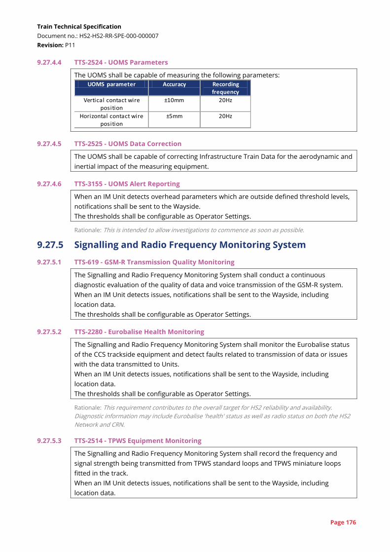
Train Technical Specification
Document no.: HS2-HS2-RR-SPE-000-000007
Revision: P11
Page 176
9.27.4.4 TTS-2524 - UOMS Parameters
The UOMS shall be capable of measuring the following parameters:
UOMS parameter Accuracy Recording frequency
Vertical contact wire position
±10mm 20Hz
Horizontal contact wire position
±5mm 20Hz
9.27.4.5 TTS-2525 - UOMS Data Correction
The UOMS shall be capable of correcting Infrastructure Train Data for the aerodynamic and
inertial impact of the measuring equipment.
9.27.4.6 TTS-3155 - UOMS Alert Reporting
When an IM Unit detects overhead parameters which are outside defined threshold levels,
notifications shall be sent to the Wayside.
The thresholds shall be configurable as Operator Settings.
Rationale: This is intended to allow investigations to commence as soon as possible.
9.27.5 Signalling and Radio Frequency Monitoring System
9.27.5.1 TTS-619 - GSM-R Transmission Quality Monitoring
The Signalling and Radio Frequency Monitoring System shall conduct a continuous
diagnostic evaluation of the quality of data and voice transmission of the GSM-R system.
When an IM Unit detects issues, notifications shall be sent to the Wayside, including
location data.
The thresholds shall be configurable as Operator Settings.
9.27.5.2 TTS-2280 - Eurobalise Health Monitoring
The Signalling and Radio Frequency Monitoring System shall monitor the Eurobalise status
of the CCS trackside equipment and detect faults related to transmission of data or issues
with the data transmitted to Units.
When an IM Unit detects issues, notifications shall be sent to the Wayside, including
location data.
The thresholds shall be configurable as Operator Settings.
Rationale: This requirement contributes to the overall target for HS2 reliability and availability.
Diagnostic information may include Eurobalise 'health' status as well as radio status on both the HS2
Network and CRN.
9.27.5.3 TTS-2514 - TPWS Equipment Monitoring
The Signalling and Radio Frequency Monitoring System shall record the frequency and
signal strength being transmitted from TPWS standard loops and TPWS miniature loops
fitted in the track.
When an IM Unit detects issues, notifications shall be sent to the Wayside, including
location data.
Train Technical Specification
Document no.: HS2-HS2-RR-SPE-000-000007
Revision: P11
Page 177
The thresholds shall be configurable as Operator Settings.
9.27.5.4 TTS-2516 - AWS Equipment Monitoring
The Signalling and Radio Frequency Monitoring System shall record the magnetic field
strength and polarities created by the AWS equipment.
When an IM Unit detects issues, notifications shall be sent to the Wayside, including
location data.
The thresholds shall be configurable as Operator Settings.
9.28 Automatic vehicle identification tag
9.28.1 TTS-1043 - AVI Tags
The Unit shall be fitted with AVI tags in accordance with HS2-NRL-RR-SPE-000-000002[119].
Rationale: CRN interface - This is necessary for compatibility with infrastructure-based monitoring
systems.
9.29 Maintenance and servicing
9.29.1 Train preparation
9.29.1.1 TTS-2041 - Automated Train Preparation Check
The Unit shall be capable of undertaking an automated check to support train preparation
as defined in the Rule Book[104].
The Unit shall check all aspects of the Unit that can reasonably be checked automatically.
It shall be possible to initiate this check automatically at a specific time, on-board, or from
the Wayside.
Rationale: This is specified to reduce the effort to undertake train preparation.
9.29.1.2 TTS-1824 - Train Preparation Certificate Review
The Unit shall record a train preparation 'certificate'.
The certificate shall include a timestamp and shall expire after a configurable amount of
time.
When a Train Captain logs in to a Train, the current train preparation certificates of all Units
in the Train shall be displayed to the Train Captain.
Rationale: This is intended to allow a Train Captain taking over a Train to confirm (if necessary) that
the Units have completed train preparation.
9.29.2 Consumable / waste monitoring
9.29.2.1 TTS-1543 - Monitoring of Consumables / Tanks
The Unit shall monitor the levels of all consumables that are replenished as part of
servicing (e.g. windscreen washer fluid or fresh water) and levels of Stored Water / solid
waste tanks that require emptying.
This information shall be reported by the Unit to the Wayside.
Train Technical Specification
Document no.: HS2-HS2-RR-SPE-000-000007
Revision: P11
Page 178
9.29.2.2 TTS-2182 - External Tank Level Indication
When the Unit is in Servicing State, each Vehicle shall display on its external PIS displays
information about the levels of all tanks / containers containing consumables or Stored
Water / solid waste.
Rationale: Depot interface - During servicing, consumables will need to be refilled and waste tanks
emptied. It will assist staff if they can see whether a tank needs filling / emptying on a display local to
the tank itself. Given the aerodynamic skirts and covers, it is unlikely that displays on tanks
themselves will be visible on the exterior of the Unit. Therefore, use of external PIS displays is
proposed as a way of presenting this information. The information would need to be readable from
track level so would need to be simple and clear, probably just identifying which tanks need
attention.
9.29.3 Software update
9.29.3.1 TTS-2482 - Update Software for Fleet
It shall be possible to make a Software Update to the Fleet from the Wayside for all non-
safety critical application software.
Rationale: Software Updates may be made to individual Units for the purpose of testing, but should
then be implemented across the Fleet.
9.29.3.2 TTS-3069 - Update Software from Wayside
Access to upload software to Units shall be controlled to ensure that appropriate
configuration control is maintained for each software element.
Rationale: This is in addition to the configurable 'Operator Settings'. It must be possible to update
software versions without having to take a laptop to each Unit, or each controller on a Unit. This is
necessary to ensure timely updates and to manage configuration across the fleet. It is recognised
that some elements of software on the Unit can only be updated locally.
9.29.4 Maintenance laptop access
9.29.4.1 TTS-2533 - Train Control Maintenance Ports
The Unit shall include a minimum of four maintenance ports, of which one shall be in each
Cab.
These ports shall allow a Maintenance Technician to connect a laptop for the purposes of
diagnostic investigations, data downloads, software uploads, etc.
It shall be possible to connect to all systems on the Unit from any maintenance port, except
where it can be demonstrated that there are safety or security justifications for limiting this
functionality.
Rationale: This is intended to allow local connection to the Unit or its systems to allow maintenance,
testing or configuration changes to be carried out without having to move to multiple locations within
the Unit.
9.29.4.2 TTS-2210 - Train-Computer Hardware Interfaces
The maintenance ports to allow connection of computers to the Unit shall be directly
compatible with an industry standard laptop PC so that bespoke interfacing hardware such
as special leads, interface boxes and dongles shall not be required between them.
Train Technical Specification
Document no.: HS2-HS2-RR-SPE-000-000007
Revision: P11
Page 179
Rationale: This requirement intends to mitigate the risk of needing to maintain a store of legacy
computer equipment.
9.29.4.3 TTS-2209 - Train-Computer Software Interfaces
Software used to interact with the Unit and any of its subsystems shall operate using a
standard, commercially available operating system and shall allow for computers used by
staff to be upgraded to future operating systems.
Rationale: This requirement intends to mitigate the risk of needing to maintain a store of legacy
computer equipment. It is envisaged that this could be achieved using interfaces based on web
browser accessible applications.
9.30 Horns
See also LOC&PAS TSI[4] §4.2.7.2 and GM/RT2131[86]
9.30.1 TTS-628 - Horn
With reference to LOC&PAS TSI[4] Section 4.2.7.2.2, the horn shall have two volumes:
a 'loud' horn compliant with EN 15153-2[42] Clause 5.2.2; and
a 'soft' horn compliant with EN 15153-2 Appendix D.
Rationale: The UK specific case of a lower horn volume is not suitable for high speed operation.
However, the loud horn volume is potentially too loud for some operation on the CRN. This is
implementing GM/RT2131[86] Clause 2.2.1.
9.30.2 TTS-1778 - Automatic Volume Varying
The horn volume shall automatically switch between loud and soft based on the speed the
Train is travelling.
It shall be possible to change the speed of transition as Software Update.
Rationale: This requirement is mandating GM/RT2131[86] Clause 2.2.2.
9.30.3 TTS-630 - Depot Warning Device
The Unit shall have a warning device of suitable volume for use in the depot.
Rationale: Normal horns are too loud to be used in the depot environment. The Train Captain can
select the appropriate warning device depending on the Unit's location.
9.30.4 TTS-1784 - Warning in Reverse
When the Train is being reversed, and only when it is being reversed, it shall be possible to
sound the horn and/or depot warning device at the rear of the Train from the front Cab.
9.31 Exterior lights
See also LOC&PAS TSI[4] §4.2.7.1 and GM/RT2131[86]
9.31.1 TTS-631 - Automatic Lights
The Unit shall enable head, marker and tail lights to be automatically set based on the
Active Cab location and Train formation.
Train Technical Specification
Document no.: HS2-HS2-RR-SPE-000-000007
Revision: P11
Page 180
9.31.2 TTS-1780 - Automatic Day / Night Headlights
The Unit shall automatically switch between day-time and night-time headlights based on
ambient light levels.
9.31.3 TTS-1779 - Manual Lighting Control
The Unit shall enable the Train Captain to switch off automatic control of the exterior lights
and manually set the lights.
The Unit shall revert to automatic control of lights when the Train Captain logs out of the
Unit.
9.31.4 TTS-1783 - Reverse Lighting
When the Unit is moved in the reverse direction, it shall display head and tail lights in a
non-standard pattern.
Rationale: This is to highlight that the Train is moving in an unusual way, and that the Train Captain
does not have full visibility. The exact arrangement will be agreed during design but may include
flashing.
9.32 Toilets and Sanitary Systems
See also section 9.16 for toilet design requirements
9.32.1 TTS-1064 - Availability Status of Toilets - on Module
The availability status of the Toilet:
available;
occupied; or
out-of-service,
shall be displayed on the outside of each Toilet, close to the door, in both text and
pictograms.
Availability status shall be visible on approach to the Toilet in any direction.
Rationale: This is to provide clarity to the full range of users as to whether the Toilet is available.
Users complain that they cannot determine whether Toilets are out of use or occupied and that
indications are not in an appropriate location. Availability should be visible on approach from any
direction which may require more than one indicator to be used.
9.32.2 TTS-693 - Availability Status of Toilets - in Saloon
The availability status (available, occupied or out-of-service) of the next Toilet along the
Unit shall be displayed at each end of each Saloon.
Rationale: This is to provide clarity whilst still in the Saloon as to the location of the nearest Toilet and
whether the Toilet is available.
9.32.3 TTS-2503 - Audible Status Announcement
When a passenger presses external access controls of an occupied or out-of-service Toilet,
an audible message confirming the Toilet is unavailable shall be played in the vicinity of the
toilet module.
Train Technical Specification
Document no.: HS2-HS2-RR-SPE-000-000007
Revision: P11
Page 181
Rationale: This is to provide information for visually-impaired passengers. It is assumed that only
Universal Access Toilets will have powered doors with controls, but powered doors may be provided
for Standard Toilets as well.
9.32.4 TTS-2157 - Availability Status of Toilets - through Unit
It shall be possible to display availability of all Toilets (free, occupied or out-of-service) in
the Unit on the colour displays.
Rationale: This enables passengers to better see where an available toilet is located.
9.32.5 TTS-1068 - Occupation Timer
If a toilet module has remained occupied for more than a configurable amount of time, an
Event shall be raised for Train Crew and an indication shall be provided on the exterior of
the toilet to alert a member of staff.
This time shall be an Operator Setting.
Rationale: This function is to alert Train Crew to Passengers that may need assistance or to possible
fare evasion. The alert does not need to be a dedicated warning indicator but could be a
combination of other indicators.
9.32.6 TTS-2641 - Discharge Water Release
The Unit shall only release Discharge Water when the Unit is below a defined speed and
the Unit is at defined Locations (Line & Distance), specific to Discharge Water.
Rationale: HS2 and CRN interface - If the Discharge Water has a high salt content it should only be
dropped while the Unit is moving at a slow speed to avoid the water being sprayed on the
underframe and causing corrosion. There are likely to be restrictions on where the Discharge Water
can be released, which will need to be agreed with the infrastructure controllers.
Cross-reference: See also Requirement TTS-3342 (Drain Stored Water) in Section 7.23.3 (Access for
servicing tasks)
9.32.7 TTS-3490 - Stored Water Release
The Unit shall only release Stored Water when the Unit is stationary and the Unit is at
defined Locations (Line & Distance), specific to Stored Water.
Rationale: HS2 and CRN interface - It is assumed that Stored Water can only be dropped when the
Unit is at a location with appropriate drainage to a sewer. The locations currently envisaged are HS2
terminal stations and depots. It may be possible to reduce this restriction with better understanding
of the likely quality of Stored Water.
9.33 Interior lighting
Cross-reference: See also Section 10.20 (Interior lighting)
9.33.1 Lighting states and levels Cross-reference: See also Section 9.7.2 (Operational states)
9.33.1.1 TTS-2050 - Passenger Service Lighting
When the Unit is in Passenger Service State, lighting shall be provided to meet the
requirements of section 10.20 of this TTS and all reading lights shall be available.
Train Technical Specification
Document no.: HS2-HS2-RR-SPE-000-000007
Revision: P11
Page 182
9.33.1.2 TTS-1097 - Servicing State Lighting
When the Unit is in Servicing State, maximum lighting shall be provided from all luminaires
in all parts of the Unit.
Rationale: Maximum lighting levels are required for cleaning and maintenance tasks.
9.33.1.3 TTS-1111 - Stand-By State Lighting
When the Unit is in Standby State, a reduced level of lighting shall be provided.
The lighting levels shall be Operator Settings.
Rationale: This is intended to reduce energy consumption and improve luminaire lifetimes by
reducing lighting when not required.
9.33.1.4 TTS-1035 - Shut-down State Lighting
When the Unit is in Shut-down State, all lighting shall be switched off.
Rationale: This is intended to reduce energy consumption and improve luminaire lifetimes by
reducing lighting when not required.
9.33.1.5 TTS-1089 - Interior Lighting Zones
The interior lighting in passenger areas shall be divided in to zones allowing the lighting
performance to be configured separately in each zone.
The zones shall be as follows:
at Seating Positions - split into Saloon Sections;
low-level lighting below Seats;
along the aisle of the Saloon - split into Saloon Sections;
ceilings in the Saloon - split into Saloon Sections;
Vestibules;
Toilets;
Gangways; and
Catering Areas.
A Saloon longer than 12m shall be split into two Saloon Sections. A Saloon less than or
equal to 12m shall be a single Saloon Section.
Rationale: The lighting concept should improve the Passenger experience and allow different areas of
the Unit to be differentiated. This may be in response to the Vehicle designation, geographic location
of the Unit or other inputs.
9.33.1.6 TTS-1462 - Switch Off lighting
It shall be possible for Train Crew or the Wayside to switch off lighting in any zone on a per-
Vehicle basis.
Rationale: This functionality is intended to be used if for any reason a particular Vehicle is not in use.
9.33.1.7 TTS-753 - Seating Position Lighting Illuminance Adjustment
It shall be possible to vary the nominal illuminance level at Seating Positions between 100
lux and 250 lux for each Saloon Section as an Operator Setting.
It shall be possible to adjust each Saloon Section as a temporary Operator Setting received
from the Wayside or from Train Crew.
Train Technical Specification
Document no.: HS2-HS2-RR-SPE-000-000007
Revision: P11
Page 183
This shall revert to the standard setting at the end of the Service.
9.33.1.8 TTS-1103 - Aisle Lighting Illuminance Adjustment
It shall be possible to vary the nominal lighting illuminance along the Saloon aisle at floor
level between 50 lux and 200 lux for each Saloon Section as an Operator Setting.
It shall be possible to adjust each Saloon Section as a temporary Operator Setting received
from the Wayside or from Train Crew.
This shall revert to the standard setting at the end of the Service.
9.33.1.9 TTS-3146 - Future Flexibility - Aisle Lighting Seating Adjustment
It shall be possible to adjust the lighting in the aisle zone to account for changes between
HS2 Seats and Premium Seats.
Rationale: Seating may be configured in a '2+2' or '2+1' configuration which will adjust the position of
the aisle. Control is required to allow the lighting illuminance to account for this change.
9.33.1.10 TTS-757 - Toilet Lighting Illuminance
It shall be possible to vary the nominal lighting illuminance in Toilets on a per-Toilet basis,
between 150 lux and 250 lux, as an Operator Setting.
Rationale: It should be possible to tune the lighting experience to provide the best possible
passenger experience.
9.33.1.11 TTS-759 - Vestibule Lighting Illuminance
It shall be possible to vary the nominal lighting illuminance in Vestibules between 75 lux
and 250 lux on a per-Vestibule basis, as an Operator Setting.
Rationale: The lighting concept should improve the Passenger experience and different areas of the
Unit to be differentiated. This may be in response to the Vehicle designation, geographic location of
the Unit or other inputs.
9.33.1.12 TTS-1855 - Lighting Arrangement in Saloon - Low Level Lighting
It shall be possible to vary the nominal lighting illuminance of low-level lighting between 0
lux (i.e. off) and 50 lux for each Saloon Section as an Operator Setting.
Rationale: This lighting is intended to be used to reduce shadowing below seats and create more
complex lighting scenes that, for example, use different colour temperatures at low level to increase
the feeling of vertical space within the saloon.
9.33.1.13 TTS-2965 - Illuminance Variation by Location
The Unit shall be able to automatically vary the illuminance of lighting across all zones due
to the Location (Line & Distance) of the Train.
It shall be possible to adjust the settings for this (e.g. lighting levels, transition locations) as
Operator Settings.
Rationale: This would permit lighting to be adjusted on the approach to stations - e.g. low level
lighting may be enhanced at these points to remind Passengers not to leave belongings behind.
Train Technical Specification
Document no.: HS2-HS2-RR-SPE-000-000007
Revision: P11
Page 184
9.33.1.14 TTS-754 - Adjustment of Lighting Colour Temperature
It shall be possible to vary the lighting correlated colour temperature between 2700 K and
6500 K in each lighting zone (TTS-1089) of each Vehicle, except ceiling (see TTS-756), as an
Operator Setting.
It shall be possible to adjust each zone as a temporary Operator Setting received from the
Wayside or from Train Crew.
This shall revert to the standard setting at the end of the Service.
9.33.1.15 TTS-756 - Ceiling Lighting - Colour Adjustment
It shall be possible to vary the colour of each ceiling zone of each Saloon Section in an
RGBW spectrum, as an Operator Setting.
It shall be possible to adjust each Saloon Section as a temporary Operator Setting received
from the Wayside or from Train Crew.
This shall revert to the standard setting at the end of the Service.
Rationale: The ceiling lighting is intended to illuminate and accent any key parts of the ceiling rather
than provide lighting for Passengers to read, work etc. Changing the colour will allow a different 'feel'
to be achieved in different parts of the Unit.
9.33.1.16 TTS-2464 - Ceiling Lighting - Response
The Unit shall be able to automatically vary the ceiling lighting to change colour or
illuminance in response to:
the Location (Line & Distance) of the Train; and
certain Events on-board.
It shall be possible to adjust the settings for this as Operator Settings.
Rationale: For example, the ceiling lighting could be used to indicate when the Train is approaching a
station or change of time of day.
9.33.1.17 TTS-752 - Adjustment of Lighting Level Based on Ambient Light Level
The lighting in each zone shall automatically adjust based on the ambient lighting
conditions. The automatic adjustment of lighting shall be designed to take in to account the
rapid changes between tunnel operation and surface operation.
This adjustment shall be separately configurable for each zone via Operator Settings.
It shall be possible to disable this feature on a per Vehicle basis via Operator Settings.
Rationale: The desired lighting level should be maintained as far as possible within the changing
ambient lighting levels expected to be experienced.
9.33.1.18 TTS-1853 - Transitions Between Lighting Levels
When lighting illuminance or colour temperature are adjusted it shall be possible to
configure the transition to allow for sudden or gradual changes between the levels.
It shall be possible to adjust the rate of transition as an Operator Setting.
Rationale: Transitions between lighting levels and colour should not be noticeable, to present a calm
and comfortable environment to Passengers. This may require transitions to take place over a
number of minutes, except in instances where a quicker response may be required, such as entering

Train Technical Specification
Document no.: HS2-HS2-RR-SPE-000-000007
Revision: P11
Page 185
tunnels during the day (when the ambient conditions present a sudden change) or an immediate
response, such as emergency situations.
9.33.1.19 TTS-1499 - Loadshed Lighting
When lighting is reduced following the loss of 25kV supply, the lighting shall transition
between different levels such that there are no instantaneous, significant reductions in
lighting.
Cross-reference: See also Requirement TTS-1176 (180-Minute Auxiliary Supply) in Section 7.7
(Auxiliary Power Supply)
See also Requirement TTS-1726 (10-Minute Auxiliary Supply) in Section 7.7 (Auxiliary Power Supply)
9.33.2 Reading lights
9.33.2.1 TTS-1809 - Reading Lights - Passenger Controls
Passengers shall be able to turn their reading light on or off and adjust the brightness of
the lighting to at least three levels using controls available at the Seating Position.
Cross-reference: See also Requirement TTS-1847 (Saloon Lighting Illuminance - At Seat Reading
Lights) in Section 10.20.3 (Illuminance levels)
9.33.2.2 TTS-1810 - Reading Lights - Remote Control
It shall be possible for Train Crew or the Wayside to switch all at seat reading lights on or
off on a per-Vehicle or per-Unit basis.
When reading lights are controlled in this way they shall default to a common brightness
level.
Rationale: This functionality is envisaged for resetting the lighting at the end of a journey or for
testing/inspection purposes.
9.33.2.3 TTS-2104 - Reading Lights and States
It shall be possible to assign a reading light status to each State such that switching states
switches all reading lights on or off as appropriate.
It shall be possible to adjust the setting per State as an Operator Setting.
Rationale: This will reset all lights when the Unit cycles through different states.
9.33.3 Cab lighting control
9.33.3.1 TTS-2052 - Train Captain Cab Lighting On/Off
The Train Captain shall be able to switch all cab lighting on or off from the cab desk or
when entering a Cab.
9.33.3.2 TTS-2053 - Train Captain Cab Lighting Adjust
The Train Captain shall be able to adjust the level of the Cab lighting from the cab desk.
Cab lighting illuminance, measured at the desk, shall be adjustable between 'off' and 250
lux with a minimum of five intermediate steps (i.e. seven total steps).
Cross-reference: See also Section 9.7.4 (Train Captain settings)
Train Technical Specification
Document no.: HS2-HS2-RR-SPE-000-000007
Revision: P11
Page 186
9.33.3.3 TTS-2054 - Train Crew Cab Lighting
Train Crew entering an Inactive Cab shall be able to switch the cab lights on or off at a
default level.
This lighting level shall be adjustable as an Operator Setting.
9.33.3.4 TTS-2055 - Cab Lighting Auto-off
Cab lighting in Inactive Cabs shall switch off after a defined period of time.
This time period shall be an Operator Setting.
It shall be possible to disable this function as an Operator Setting.
9.34 Interior Doors
9.34.1 This section contains the requirements for Interior Doors. Interior Doors include (where
included in the Unit design) vestibule doors, partition doors and gangway doors.
Requirements for other doors included in the interior of Units, e.g. toilet doors are covered
separately.
9.34.2 TTS-720 - Interior Door Operation
All Interior Doors shall be power operated.
9.34.3 TTS-3022 - Glazed Interior Doors
The majority of each Interior Door leaf shall be glazed.
Rationale: Glazed doors provide a more welcoming environment and are also necessary for fire
situations.
9.34.4 TTS-719 - Manage Unit on Canted Track
All Interior Doors shall be operable in the full range of Normal Operation including the full
range of cant deficiencies.
Rationale: It is not acceptable for interior doors to fail to open, close or remain closed due to the
track cant or the dynamic movement of the Vehicles.
9.34.5 TTS-1041 - Interior Door Controls 1
It shall be possible to configure, as an Operator Setting, all Interior Doors such that in
Normal Operation, they can be opened by:
a push button;
a sensor; or
a combination of both.
Rationale: The HS2 Train Operator will want to retain the flexibility to optimise the operation of
Interior Doors based on User needs.
9.34.6 TTS-1536 - Interior Door Controls 2
The controls used for operation of Interior Doors and their positioning shall be consistent
across all Interior Doors.
Train Technical Specification
Document no.: HS2-HS2-RR-SPE-000-000007
Revision: P11
Page 187
Rationale: It is considered important to ensure passenger controls are consistent to allow Units to be
used intuitively. If doors between Saloons and Vestibules have different controls to those at
Gangways, this can be confusing walking through the Unit.
9.34.7 TTS-729 - Auto-Close of Interior Doors
After a configurable period, Interior Doors shall close automatically.
This time shall be separately configurable as Operator Settings for different types of
Interior Doors.
Rationale: Interior Doors must close to provide the appropriate ambience within the Saloon and
provide a fire barrier. However, the HS2 Train Operator will want to retain the flexibility to optimise
the operation of Interior Doors.
9.34.8 TTS-730 - Interior Door Close Check
Interior doors shall include functionality to ensure they do not initiate closing if a
Passenger is positioned within an area the full width of the door clearway and extending
200mm from either face of the door.
It shall be possible to configure this function on and off as an Operator Setting.
Rationale: This requirement is intended to avoid issues seen on some current Units where doors
close on Passengers waiting to disembark. It is desirable that the door is not prevented from closing
if a bag is left adjacent to the door.
9.34.9 TTS-721 - Configurable Operation of Interior Doors
The opening and closing speeds of Interior Doors as well as any delays used in their
operation shall be configurable as an Operator Setting.
Rationale: The HS2 Train Operator will want to retain the ability to optimise the operation of Interior
Doors.
9.34.10 TTS-722 - Interior Door Obstacle Detection
All Interior Doors shall include an obstacle detection function that shall cause the door to
re-open.
The parameters for obstacle detection in Interior Doors shall be configurable as Software
Updates.
Rationale: The Interior Doors should not close and trap passengers as occurs on some current UK
rolling stock.
9.34.11 TTS-1814 - Interior Doors Evacuation Requirements 1
It shall be possible for the full User Population to manually open Interior Doors from either
side.
There shall be clearly identifiable handholds for this purpose.
Rationale: This is to ensure that interior doors can be used in an emergency scenario, either because
power to the Interior Doors has failed or the Interior Doors are not responding to commands due to
fire detection (TTS-1835)
Train Technical Specification
Document no.: HS2-HS2-RR-SPE-000-000007
Revision: P11
Page 188
9.34.12 TTS-1047 - Interior Doors Evacuation Requirements 2
If single-leaf Interior Doors are fitted at a location, Interior Doors at opposite ends of the
Vehicle shall open in opposite directions.
Rationale: This is to ensure that if the Vehicle overturns, Passengers can escape from the Vehicle in at
least one direction. This is not applicable to bi-parting doors.
9.34.13 TTS-2531 - Interior Doors Evacuation Requirements 3
Interior Doors positioned between a Saloon and the nearest emergency exit shall be fitted
with glazing that includes a mechanism to allow it to be removed in an emergency.
Rationale: This requirement is intended to allow for situations where it is no longer possible to open
an interior door due to deformation of the door or frame.
9.34.14 TTS-3016 - Lock-out Interior Doors
It shall be possible mechanically lock-out Interior Doors, such they do not respond to
commands and cannot be manually opened.
Rationale: This may be necessary operationally (e.g. if a Vehicle is damaged).
9.34.15 TTS-1813 - Automatic Interior Door Opening - Stations
Interior Doors on a normal route from Seating Positions to the platform shall automatically
open when the Train is approaching a platform, and shall remain open until the Train has
departed the platform and no Passengers are detected.
It shall be possible to inhibit / enable this function for different stations and different times
of year as an Operator Setting.
Rationale: The need to open Interior Doors (and them automatically re-closing on some existing
rolling stock) causes delay to Dwell Times. The Interior Doors to be opened will depend on the layout
of Vehicles and their vestibules.
9.34.16 TTS-2175 - Automatic Interior Door Opening - Maintenance / Servicing State
It shall be possible to configure all Interior Doors to open and stay open while a Unit is in
Servicing State.
Rationale: This would ease cleaning and maintainers who may need to walk through the whole Unit.
9.34.17 TTS-1178 - Synchronisation of Gangway Doors
With reference to PRM TSI[6] Clause 4.2.2.3.3 (5), where consecutive Interior Doors are fitted
either side of a Gangway, both doors shall open synchronously as a pair.
Rationale: This is to clarify the optional functionality described in PRM TSI Clause 4.2.2.3.3(5).
9.34.18 TTS-2872 - Temporary Interior Door Inhibit
If an internal clearway of the gangway is not sufficient to permit a wheelchair to move
between Vehicles on curved track, as defined in EN 16286-1[48] in any operational situation,
it shall be possible to configure, as an Operator Setting, Interior Doors adjacent to
Gangways close to Wheelchair Spaces such that they do not respond to passenger controls
at certain Locations (Line & Distance).
Train Technical Specification
Document no.: HS2-HS2-RR-SPE-000-000007
Revision: P11
Page 189
Rationale: It is unlikely this function would be enabled at Acceptance. If additional Wheelchair Spaces
are later fitted to the Unit, the preference is to use the existing Universal Toilets accessed via the
Gangway. It is unlikely that an 800mm clearway through the gangway can be achieved over the full
range of curves and reverse curves, but it should be possible over the significant majority of the
route. Therefore, temporarily inhibiting the doors at locations with tight curvature may be a solution
to mitigate this issue. Such a solution would only be implemented following a review of the safety of
such a function.
9.34.19 TTS-3477 - Open All Interior Doors
It shall be possible to command all Interior Doors on the Train to open and remain open
until the command is removed.
It shall be possible to initiate and cancel this control from both the Cab and Crew Control
Point.
This command shall be cancelled for any Interior Doors affected by a detected fire.
Rationale: This command would support emergency ventilation by opening Exterior Doors. Closing
doors to maintain a fire barrier must take priority over this.
9.35 Cleaning sockets
9.35.1 TTS-880 - Cleaners Sockets
A 13A, RCD-protected, 3-pin Socket shall be provided in each vehicle for cleaning
equipment in or close to each vestibule.
9.35.2 TTS-1992 - Automatic Socket Switch-off
The sockets for cleaning shall automatically be switched on when the Unit is in Servicing
State and switched off when the Unit is in Passenger Service State.
9.36 Clocks / time
9.36.1 TTS-438 - Time Synchronisation
The internal clocks of all on-board systems shall be synchronised with an external source
to maintain time to an accuracy of better than ±1s per day.
Rationale: This is intended to ensure that on-board and trackside systems are synchronised as well as
ensuring that any data downloads are accurately timestamped to allow accurate investigation.
9.36.2 TTS-2264 - Timestamping
All data timestamping shall record the time
in seconds; and
in UTC and British Summer Time (UTC +1) when applicable.
Rationale: In particular, UTC is required for all on-board and trackside CCS systems to enable
synchronisation of data exchanges between sub-systems.
Train Technical Specification
Document no.: HS2-HS2-RR-SPE-000-000007
Revision: P11
Page 190
9.37 Staff communication
9.37.1 TTS-3403 - Written Orders
It shall be possible for traffic management controllers at the NICC to send written orders
(as defined by OPE TSI Appendix A Annex A[10A]) to a particular Unit. The written order shall
be displayed to the Train Captain and stored on-board the Unit.
Rationale: A written order would normally be written by a driver to record an instruction received
from a signaller in an abnormal situation. Under ERTMS there are a defined set of written orders.
The goal of this requirement is for traffic management controllers (a similar role to signallers) to be
able to transmit this message to the Unit so that Train Captain does not need to write this down and
there is less risk of the message being corrupted.
9.37.2 TTS-3434 - Train Crew Communication
It shall be possible to send text-based messages from the Wayside to:
Train Crew to be viewed via the Crew Control Point; and
the Train Captain to be viewed in the cab.
(Note that this is not requiring the ability to receive SMS messages.)
Rationale: Wayside staff may need to provide information to Train Crew for issues such as providing
assistance to Passengers at a particular station, or warning of upcoming delays. Some messages
could be automatically generated on the Wayside.
9.37.3 TTS-3435 - Not to be Moved Message
It shall be possible to display a 'Not to be moved' message on screens in the Cab, at Crew
Control Points and on external passenger information displays.
It shall be possible to trigger this message on the Unit or from the Wayside.
Rationale: This would be used if a Unit was undergoing maintenance, cleaning or some other
intervention. It may supplement or replace a physical sign.
10 Interior Design and Components 10.0.1 This section gives requirements for the interior components and their general integration
into the interior of the Unit. These components are used to define the interior layouts
defined in Section 11.
10.0.2 The requirements of this section are all subject to development via the interiors
collaboration process described in MSA Schedule 9, Appendix 1.
10.1 Human factors
10.1.1 This section gives some human factors requirements for the rolling stock. This set of
requirements is not exhaustive and the TMM is required to develop and implement a
human factors plan as detailed in MSA Schedule 9, Appendix 3.
Train Technical Specification
Document no.: HS2-HS2-RR-SPE-000-000007
Revision: P11
Page 191
10.1.2 TTS-291 - User Population (PQTS-352)
The Unit shall be suitable for a population spanning the 5th-percentile adult female to the
95th-percentile adult male. The PeopleSize dataset[110] shall be used for any
anthropometric measurements, adjusted for predicted secular growth over the life of the
Unit and taking into account allowances for typical clothing (including protective
equipment) worn by the user groups.
Rationale: This is HS2's preferred dataset. This requirement is in addition to the requirements
concerning anthropometric measurements in the LOC&PAS TSI[4].
10.1.3 The population described in TTS-291 is defined as the User Population.
10.1.4 TTS-1920 - Crew and Captain Usability of Design
The Unit shall enable the Train Captain and Train Crew, with appropriate training, to
operate the Train in a safe, reliable and efficient manner.
10.1.5 TTS-1919 - Passenger Usability of Design
The Unit and its systems shall be safe, easy and intuitive for Passengers to use and interact
with.
10.1.6 TTS-2588 - Passenger Impairments
The design of the Unit shall take account of any permanent or temporary physical, mental,
intellectual or sensory impairments that Passengers may have.
Rationale: The design of the Unit needs to consider the full range of people with disabilities and
people with reduced mobility, which is defined in the PRM TSI[6] as any person who has a permanent
or temporary physical, mental, intellectual or sensory impairment which, in interaction with various
barriers, may hinder their full and effective use of transport on an equal basis with other passengers
or whose mobility when using transport is reduced due to age.
10.1.7 TTS-2206 - Elimination of Cross System Errors
Where Passengers, the Train Captain, Train Crew and Maintenance Technicians interact
across multiple on-board systems, the designs shall be consistent, and not generate cross
system errors.
Rationale: This is intended to remove instances where users' knowledge of one system can influence
how they use another e.g. blue means 'ok' on one system and cancel on another. Users will see the
Unit as a single system despite it being it being assembled from multiple suppliers.
10.1.8 TTS-2208 - Ambiguity of Controls
All controls should be uniquely identifiable and unambiguous.
10.1.9 TTS-2268 - Control Visibility
All Cab controls and indications shall be clearly legible from the Train Captain's position
over the full range of ambient lighting levels and incidence angles.
Rationale: The Train Captain's controls and indications should be arranged to provide clarity of the
displays when taking into account the cab environment, including screen position, sources of
Train Technical Specification
Document no.: HS2-HS2-RR-SPE-000-000007
Revision: P11
Page 192
sunlight, the position of the Train Captain (including viewing angles), cab lighting levels, maximum
night-time cab illumination levels, reflections of reflective clothing, etc.
10.1.10 TTS-2875 - Musculoskeletal Disorders
Train Captain, Train Crew and Maintenance Technician's facilities and interfaces shall be
designed to ensure users are protected from developing musculoskeletal disorders.
Rationale: Facilities and interfaces should be designed to allow repeated and continuous use if
necessary without causing harm to users.
10.1.11 TTS-790 - Lack of finger traps
There shall be no accessible holes or gaps between fixed or moveable panels, fixtures,
components or equipment that could cause injury by trapping fingers, hands or any other
body parts. A finger trap shall be as defined in EN 1176-1[30] Section 4.2.7, or appropriate
alternative standard.
10.1.12 TTS-2847 - Design for PRM Use
The Unit shall be designed for PRM use and shall be compliant with the rolling stock
requirements of EN 16584-1[49], EN 16584-2[50] and EN 16584-3[51].
10.2 Industrial design
10.2.1 This section gives some very high-level requirements to guide the industrial design of the
Unit. The design of the interior will be developed through the interiors collaboration
process defined in MSA Schedule 9, Appendix 1.
10.2.2 TTS-1916 - Passenger-facing Appearance
Interfaces between Passengers and the Unit shall have a modern, uncluttered appearance
that embodies the values set out in the HS2 Design Vision[127].
10.2.3 TTS-1917 - Consistent Design Theme
Passengers shall be presented with a consistent design theme throughout their
interactions with the Unit, including consistent controls and visual themes.
10.2.4 TTS-1918 - Material Finish
Materials and finishes on the interior shall give Passengers the impression of a high quality
service, while also meeting requirements for robustness, cleanability, graffiti-resistance,
etc.
10.2.5 TTS-3442 - Material Aesthetic Finish Duration
Materials and finishes on interior trim and luggage storage areas shall maintain Minimum
Aesthetic Standards for:
4 years for locations that are likely to be in contact with bicycles, luggage and catering
trolleys; and
8 years for all other interior trim, grab-handles, seat backs and tables
Train Technical Specification
Document no.: HS2-HS2-RR-SPE-000-000007
Revision: P11
Page 193
Rationale: This requirement aligns with rules on developing the Maintenance Plan in MSA Paragraph
4.9.
10.3 Passenger Seats
See also GM/RT2100[83] section 6.2.
10.3.0.1 Requirements in this section are listed in the following sections:
10.3.1 - General seat design - which applies to all types of Passenger Seat;
10.3.2 - HS2 Seat - which applies to the 'HS2 Seat' that will provide 2+2 seating in at
least the majority of the Unit; these requirements also apply to the Tip-up Seat;
10.3.3 - Tip-up Seat - which applies to the Tip-up Seat only, a sub-type of HS2 Seat
that can be raised to provide a clear area;
10.3.4 - Premium Seat - which applies to the 'Premium Seat' that may be used to
provide 2+1 seating in some vehicles, depending the final layout decisions;
10.3.5 - At-seat facilities - which defines facilities that apply to all 'Seating
Positions'; and
10.3.6 - Vestibule Seats - which applies to provision for seating to be provided in
the vestibules.
10.3.1 General seat design
10.3.1.1 TTS-1801 - Seat Comfort
Passenger Seats shall be comfortable for the User Population, for the range of journey
lengths that are possible on HS2 services and whilst completing tasks likely to be
undertaken by Passengers.
Rationale: The comfort of seat should not only consider Passengers seated in an ideal position, since
Passengers may not adopt this position. For example, Passengers may spend the journey resting,
reading, working on a laptop or watching a video on a phone or tablet.
10.3.1.2 TTS-654 - Seat Functionality - Recline
It shall be possible to recline Passenger Seats (except Tip-up Seats) to allow for at least two
distinct seating positions.
The action of reclining a seat shall not affect the space available to the Passenger behind.
Rationale: This is considered to be important to providing comfort to Passengers and the 'tasks' they
may undertake while seated.
10.3.1.3 TTS-1683 - No Under-Seat Obstructions
Passenger Seats shall have no obstruction under the seat in an area:
±200mm from the centre-line of the seat, except between the seat centre-line and an
adjacent sidewall;
150mm between the centre-line of the seat and an adjacent sidewall;
250mm up from the floor; and
Train Technical Specification
Document no.: HS2-HS2-RR-SPE-000-000007
Revision: P11
Page 194
400mm forward from the rearmost part of the seat
Rationale: There should be no intrusions under seats that may reduce the comfort of Passengers
seated in the seat behind, or prevent luggage being stowed at floor level. This requirement applies to
the Passenger Seat, which includes its mountings to the wall and vertical legs. Wall-mounted heaters
that may also encroach into this space are managed by requirement TTS-633.
Cross-reference: See also Requirement TTS-1662 (Under-Seat Storage Provision) in Section 10.3.5 (At-
seat facilities)
10.3.1.4 TTS-655 - Display of Seat Numbers
Two-digit seat numbers shall be displayed on each Passenger Seat such that they can be
clearly read by the full User Population from the aisle in any position within 1m of the seat.
The seat number shall remain visible when the seat is occupied.
Rationale: It should be easy for Passengers moving through the Saloon to locate the correct seat.
This supports minimisation of dwell time. Note that identification will be required for Wheelchair
Spaces, but this is assumed to be achieved via labelling.
10.3.1.5 TTS-1510 - Prevention of Pick-pocketing
Passenger Seats shall be designed to help prevent pick pocketing from behind the seats.
Rationale: Passengers should be able to relax when travelling and feel that they and their belongings
are secure.
10.3.1.6 TTS-329 - Future Flexibility - Move seats
Passenger Seats and their interface to the Unit shall enable the position of seats to be
moved without affecting floor coverings or interior panelling, except for cover-strips on
mechanical fixtures and electrical / data connections.
Rationale: It should be possible for the interior layouts of the Units to be easily reconfigured to take
in to account changes in demand and Passenger needs over the life of the Units.
10.3.1.7 TTS-2060 - Future Flexibility - Re-use seats
It shall be possible to re-use the majority of a single Passenger Seat in another position in
the Saloon.
The main structure of individual seats shall not be handed so that they can only be fitted to
one side of the Vehicle.
Rationale: To enable future re-configuration, it should be possible to move and re-use seats. This
includes removing a pair of seats from its mounting and re-using the two individual seats at another
location.
10.3.1.8 TTS-3443 - Minimum Aesthetic Passenger Seat Characteristics
Passenger Seats coverings and cushions shall maintain Minimum Aesthetic Standards for 8
years, provided that seat covers are deep cleaned, away from the Unit, every 2 years.
Rationale: This requirement aligns with rules on developing the Maintenance Plan in MSA Paragraph
4.9.

Train Technical Specification
Document no.: HS2-HS2-RR-SPE-000-000007
Revision: P11
Page 195
10.3.1.9 TTS-3480 - Passenger Seat Fire Performance
With reference to LOC&PAS TSI[4] Clause 4.2.10.2.1, Passenger Seats shall be tested for fire
performance in accordance EN 16989[52A] instead of Annex A and B of EN 45545-2[53].
Rationale: EN 16989 includes improved tests compared to EN 45545-2 Annex A and B. It is planned
that EN 16989 will replace Annex A and B so that it is ultimately referenced by a future version of the
LOC&PAS TSI.
10.3.2 HS2 Seats
10.3.2.1 TTS-639 - Minimum Seat Width - HS2 Seat - Mandatory
The width of the cushioned area of each HS2 Seat, and the space between the armrests,
shall be shall not be less than 450mm.
10.3.2.2 TTS-1981 - Seat Clearance - HS2 Seat
The installation of HS2 Seats shall ensure, as a minimum:
airline seating - 150mm horizontal clearance between the front of a 95th-percentile male
knee and any part of the seat in front within a vertical zone between the top and bottom of
the thigh; and
bay seating - 300mm horizontal clearance between the knees of two 95th-percentile males
sitting opposite each other.
In both cases, measurements shall be based on the normal expected seating position for
the chosen seat with no recline.
Rationale: These definitions have been developed to ensure a good level of comfort when seated.
The space available for each passenger needs to take in to account the space required for the seats
to deliver the appropriate facilities and comfort to each Passenger. This requirement needs to be
complied with in combination with the seat pitch dimensions specified as part of the layouts in
Section 11.
Cross-reference: See also Requirement TTS-2239 (Seat Pitch) in Section 11.1.1 (Passenger Seats)
10.3.2.3 TTS-646 - Provision of Armrests - HS2 Seat - Mandatory
All HS2 Seats shall be fitted with moveable armrests on both sides.
A single armrest may be fitted between two HS2 Seats.
10.3.2.4 TTS-3151 - Armrest Rotation - HS2 Seat
Armrests on HS2 Seats shall be capable of rotating to a position in line with the seat back
cushion.
The armrest closest to the sidewall may be restricted from moving.
Rationale: Moveable armrests are required to allow easier access to all seats, not just those
designated as priority seats. The armrest adjacent to the sidewall could cause a finger trap if it
moved.
10.3.2.5 TTS-647 - Armrest Width - HS2 Seat - Mandatory
Armrests fitted to HS2 Seats shall have a width of no less than 50mm.
Train Technical Specification
Document no.: HS2-HS2-RR-SPE-000-000007
Revision: P11
Page 196
10.3.2.6 TTS-651 - Seat Materials - HS2 Seat
The material to be used to finish the HS2 Seats shall be a moquette type fabric which shall
be demonstrated to have sufficient abrasion resistance and burst strength to be fit for
purpose.
10.3.3 Tip-up Seats
10.3.3.1 Tip-up Seats are used for the Multi-Purpose Area described in Section 10.5. They are
arranged in transverse positions. They are a sub-type of the HS2 Seat and all requirements
applicable to the HS2 Seat, except recline (TTS-654) also apply to these seats.
10.3.3.2 TTS-972 - Use of Tip-Up Seats
Tip-up Seats shall only be used in the Saloon
in a transverse configuration; and
as part of the Multi-Purpose Areas.
Rationale: All passengers should be provided with a consistent level of experience and as such,
longitudinal tip-up seats are not considered acceptable.
10.3.3.3 TTS-970 - Tip-Up Seat Lock Up and Down
Tip-up Seats shall provide facilities to enable them to be locked in the up or down position
by an Authorised Person.
Rationale: This is to provide operational flexibility in the use of Multi-Purpose Areas.
10.3.3.4 TTS-971 - Tip-Up Seat Mechanism
Tip-up Seats shall return to a vertical position when not in use and not locked in the down
position.
Rationale: This is to allow seats to be used in a tip-up configuration to improve access.
10.3.3.5 TTS-966 - Tip-Up Seat Structural Design
Tip-up Seats and supporting structures shall withstand proof and fatigue loads applied to
the seat throughout its lifetime.
Rationale: If Tip-Up seats are used in Multi-Purpose Areas then they need to be assured to deliver
reliable performance over their full life.
10.3.4 Premium Seats
10.3.4.1 TTS-640 - Minimum Seat Width - Premium
The width of the cushioned area of a Premium Seat, and the space between the armrests,
shall not be less than 500mm.
10.3.4.2 TTS-2599 - Seat Clearance - Premium Seat
The installation of Premium Seats shall ensure, as a minimum:
airline seating - 150mm horizontal clearance between the front of a 95th-percentile male
knee and any part of the seat in front within a vertical zone between the top and bottom of
the thigh; and
Train Technical Specification
Document no.: HS2-HS2-RR-SPE-000-000007
Revision: P11
Page 197
bay seating - 300mm horizontal clearance between the knees of two 95th-percentile males
sitting opposite each other.
In both cases, measurements shall be based on the normal expected seating position for
the chosen seat with no recline.
Rationale: These definitions have been developed to ensure a good level of comfort when seated.
The space available for each Passenger needs to take in to account the space required for the seats
to deliver the appropriate facilities and comfort to each Passenger. This requirement needs to be
complied with in combination with the seat pitch dimensions specified as part of the layouts in
Section 11.
10.3.4.3 TTS-648 - Armrest Width - Premium
Armrests fitted to Premium Seats shall have a width of no less than 80mm.
10.3.4.4 TTS-1868 - Provision of Armrests - Premium
All Premium Seats shall be fitted with movable armrests on both sides.
A single armrest of double width (i.e. 160mm) may be fitted between two Premium Seats.
Rationale: A single central arm-rest removes the risks of trapping fingers between two adjacent arm-
rests. Two armrests would need a separation to prevent this.
10.3.4.5 TTS-3177 - Armrest Rotation - Premium
Armrests fitted to Premium Seats shall be capable of rotating to a position in line with the
seat back cushion.
The armrest closest to the sidewall may be restricted from moving.
Rationale: Moveable armrests are required to allow easier access to all seats, not just those
designated as priority seats. The armrest at the sidewall can create a risk of trapping if it moves, but
the seat may be moved to a different position in the future so the restriction should be temporary.
10.3.4.6 TTS-652 - Seat Materials - Premium
The material to be used to finish the Premium Seats shall be a leather-like fabric which
shall be demonstrated to have sufficient abrasion resistance and burst strength to be fit for
purpose.
10.3.5 At-seat facilities
10.3.5.1 The requirements in this section apply to each Seating Position, which includes Wheelchair
Spaces and seats in the Multi-Purpose Area when configured as seats. Note that
requirements for facilities to move with the seat only apply to Passenger Seats and not to
the Wheelchair Spaces.
10.3.5.2 TTS-662 - At-Seat Power - 3-Pin Socket
A 3A 230V 3-pin Socket shall be provided for each Seating Position, i.e. one socket per
Seating Position.
For Passenger Seats, if the associated seat is reconfigured during the life of the Unit, this
facility shall be moveable with the seat to any position within the Saloon.
Train Technical Specification
Document no.: HS2-HS2-RR-SPE-000-000007
Revision: P11
Page 198
Rationale: All Passengers should have access to power for laptops or other electrical devices for
which a USB provides insufficient power, or the passenger does not have the correct adaptor.
Cross-reference: See also Requirement TTS-333 (Wheelchair Charging) in Section 10.7 (Wheelchair
Spaces)
10.3.5.3 TTS-663 - At-Seat Power - Low Voltage
A USB Type A power socket shall be provided for each Seating Position. Connectors shall be
designed to be upgraded and easily replaced in the event of damage.
For Passenger Seats, if the associated seat is reconfigured during the life of the Unit, this
facility shall be moveable with the seat to any position within the Saloon.
Rationale: All Passengers should have access to power for mobile phones, tablets, etc.
10.3.5.4 TTS-2062 - Future Flexibility - Replacement Low Voltage
It shall be possible to replace the USB Type A socket (TTS-663) with a USB Type C or other
low voltage socket without moving the seat or other internal equipment.
Rationale: It is considered likely that USB Type A will no longer be the 'standard' connector either
during the design / manufacture of the vehicles, or shortly after introduction.
10.3.5.5 TTS-2032 - Positioning of Power Sockets
Both 230V (TTS-662) and low voltage (TTS-663) sockets shall be positioned so as:
to be visible to seated Passengers;
to not require Passengers to reach across each other to use them; and
minimise the risk of accidental damage or contact with fluids.
Rationale: All Passengers should have easy access to power for their devices.
10.3.5.6 TTS-664 - Coat Hook
A coat hook shall be provided at each Seating Position.
This facility shall be moveable with the seat to any position within the Saloon.
Rationale: This is to ensure that Passengers can keep their belongings close by if they wish.
10.3.5.7 TTS-665 - Reading Light Provision
A reading light shall be provided at each Seating Position.
This facility shall be moveable with the seat to any position within the Saloon.
Rationale: This is to provide a level of control over the lighting level at a Seating Position.
Cross-reference: See also Requirement TTS-1847 (Saloon Lighting Illuminance - At Seat Reading
Lights) in Section 10.20.3 (Illuminance levels)
10.3.5.8 TTS-660 - Cup Holder Provision
A cup holder shall be provided at each Seating Position.
The cup holder should enable either a bottle of up to 75mm diameter and a minimum
height of 200mm or a cup with a base diameter of 55mm and a top diameter of 75mm and
a height of 95mm to be secured.
Train Technical Specification
Document no.: HS2-HS2-RR-SPE-000-000007
Revision: P11
Page 199
The use of the cup holder shall not preclude the use of a laptop on the table provided at
that seat.
For Passenger Seats, if the associated seat is reconfigured during the life of the Unit, this
facility shall be moveable with the seat to any position within the Saloon.
Rationale: Passengers are likely to bring drinks with them, or buy drinks on-board. The cup-holder
should hold the widest range of drinks containers.
Cross-reference: See also Section 10.4 (Tables)
10.3.5.9 TTS-2468 - Small Item Storage
Storage for small items, such as a mobile phone, shall be provided at each Seating Position.
The use of this storage shall not preclude the use of a laptop on the table provided at that
seat.
For Passenger Seats, if the associated seat is reconfigured during the life of the Unit, this
facility shall be moveable with the seat to any position within the saloon.
Rationale: This feature is to provide the ability for Passengers to keep important items close at hand.
10.3.5.10 TTS-1662 - Under-Seat Storage Provision
Passenger Seats in airline arrangement shall include features that allow bags to be stored
under the seat in front of where a Passenger is sitting.
These features shall prevent bags moving forward in to the space provided for the
Passenger in front.
This facility shall be moveable with the seat to any position within the Saloon.
Rationale: If passengers decide to use the under seat space for storing their bags they should be
confident that it will not slide forward or be taken by the passenger in front.
Cross-reference: See also Requirement TTS-1683 (No Under-Seat Obstructions) in Section 10.3.1
(General seat design)
10.3.5.11 TTS-2211 - Fitment of Hearing Aid Induction Loops to Priority Seats
All Seating Positions designated as priority seats shall be covered by induction loops,
compliant with the requirements of BS 7594[26] and EN 60118-4[66], for relaying PIS audio
messages to Passengers with hearing aids.
This facility shall be movable with the seat to any position within the Saloon.
Rationale: This is intended to ensure that Passengers with hearing impairments can receive PIS audio
messages clearly.
10.3.5.12 TTS-2212 - Future Flexibility - Provision for Induction Loops
All Seating Positions shall be provisioned for coverage by induction loops for relaying PIS
audio messages to Passengers with hearing aids.
This provision shall include all mountings, power and data connections required to allow
fitment of the devices in a depot.
Rationale: This is intended to provide flexibility to increase the number of induction loops fitted
during the lifetime of the Units.
Train Technical Specification
Document no.: HS2-HS2-RR-SPE-000-000007
Revision: P11
Page 200
10.3.6 Vestibule Seat
10.3.6.1 Vestibule Seats, if fitted, will be primarily used by staff to support specific duties related to
the fire and evacuation strategy. The seats may also be used by Passengers in specific
scenarios. There is no requirement to provide the Vestibule Seats at this stage, however
provision for their fitment should be included in the design.
Note: Vestibule Seats will not be considered as Seating Positions.
10.3.6.2 TTS-3294 - Future Flexibility - Vestibule seat provision
All Vestibules shall be capable of accommodating a minimum of one Vestibule Seat. This
provision shall assume a suitable seat that can be folded away when not in use and can be
used by the full User Population. The provision shall at least include the structural
elements to mount the Vestibule Seat.
10.4 Tables
See also GM/RT2100[83] Section 6.3
10.4.1 Bay tables
10.4.1.1 TTS-670 - Provision of Tables in Bays
Fixed tables shall be fitted in all bay seating positions, except Multi-Purpose Areas.
10.4.1.2 TTS-1007 - Provision of Fold-Away Tables in Multi-Purpose Areas
Multi-Purpose Areas shall be fitted with a table capable of being folded away to leave the
floor areas between the seats clear for other uses.
Rationale: It is key to maximise the floor area left free when the fold-away table is in the stowed
position to allow Multi-Purpose Areas to be used for storage of items such as luggage or pushchairs.
10.4.1.3 TTS-1495 - Size of Fixed Tables
Fixed and fold-away tables shall be sized to ensure that they can accommodate and
support a reference laptop for each passenger in the bay, whilst in use, with 15.1" display
and a footprint of 350mm × 250mm. It shall be possible for the User Population to type on
the laptop and angle the screen for reading when the Passenger's seat recline is in the
upright position.
Rationale: All Passengers should be provided with sufficient space to use their devices and work if
necessary.
10.4.1.4 TTS-1147 - Fold-Away Table Lock Up and Down
Fold-away tables shall provide a facility that enables them to be locked in the up or down
position by an Authorised Person.
Rationale: This is to provide operational flexibility in the use of multi-purpose areas
Train Technical Specification
Document no.: HS2-HS2-RR-SPE-000-000007
Revision: P11
Page 201
10.4.1.5 TTS-2167 - Future Flexibility - Table Flexibility
Fixed and fold-away tables and their interface to the Unit shall enable the position of tables
to be moved without affecting floor coverings or interior panelling, except for cover-strips
on mounting points and electrical connections.
Rationale: It should be possible for the interior layouts of the Units to be easily reconfigured to take
in to account changes in demand and user needs over the life of the Units.
10.4.2 Seat back tables
10.4.2.1 TTS-658 - Provision of Seat-Back Tables
All Passenger Seats arranged in an airline configuration shall be provided with a Seat-back
Table mounted to the seat in front or other structure if there is no seat in front.
Rationale: All passengers should have access to a table. If seats face a partition, they should be
provided with a table fitted to the partition.
10.4.2.2 TTS-659 - Size of Seat-Back Table
All Seat-back Tables shall be capable of fully accommodating and supporting a reference
laptop whilst in use, with 15.1" display and a footprint of 350 × 250mm. It shall be possible
for the User Population to type on the laptop and angle the screen for reading when their
seat recline is in the upright position.
Rationale: The experience at Passenger Seats in airline configuration should, as far as possible, match
bay seats. The design should ensure that seat-back tables allow comfortable use of a laptop
computer by the full range of Passengers. A pull-out extension to the table may be necessary to
support the laptop
10.4.2.3 TTS-1494 - Tablet/Phone Holder Built in to Seat-Back Table
Seat-back Tables, or other features on the seat, shall allow a mobile phone or tablet
computer to be held in a standing position suitable for viewing the screen. The features
should account for a range of sizes of device.
Rationale: The design of airline seats should ensure that Passengers are able to make best use of
their devices.
10.4.2.4 TTS-1234 - Future Flexibility - Provision to Add Seat-Back Tables
All Passenger Seats shall be capable of providing a Seat-back table to a Seating Position
behind. When the seat is positioned so that the table is not usable (e.g. when the seat back
is against a luggage stack), the table shall either be removed or be protected from damage.
The changes required shall be possible in the depot.
Rationale: It should be possible to reconfigure the Saloon, re-using existing components as far as
possible. As such, it may be necessary to add or remove seat-back tables to seats depending on
whether they are in an airline or back-to-back configuration.
10.5 Multi-Purpose Areas
10.5.1 TTS-975 - Multi-Purpose Areas - Contents
Multi-Purpose Areas shall contain four Tip-up Seats and a fold-away bay table.
Train Technical Specification
Document no.: HS2-HS2-RR-SPE-000-000007
Revision: P11
Page 202
Rationale: Multi-Purpose areas are intended to allow flexibility to provide features such as additional
luggage storage, buggy storage, etc. and as such require the ability to create additional floor space.
Cross-reference: See also Section 10.3.3 (Tip-up Seats)
10.5.2 TTS-1539 - Multi-Purpose Areas - Definition
Multi-Purpose Areas shall normally operate as a seating bay, including a table.
It shall be possible for one Authorised Person to reconfigure the Multi-Purpose Area to
provide empty floor space to be used for storage of luggage or other items such as push-
chairs.
It shall be possible to lock the furniture in either state.
Rationale: Multi-Purpose areas are intended to allow flexibility to provide features such as additional
luggage storage, buggy storage, etc. and as such require the ability to create additional floor space.
10.6 Luggage storage
See also GM/RT2100[83] section 6.8.
10.6.0.1 "Large Bags" shall be defined as having dimensions of 800 × 570 × 300mm
10.6.0.2 "Small Bags" shall be defined as having dimensions of 560 × 450 × 250mm
10.6.0.3 A "Bicycle" shall be defined as a bicycle with 740mm wheels, a 580mm frame (i.e. seat tube
measurement), 1050mm wheelbase and 460mm width handlebars
10.6.1 Overhead luggage racks
10.6.1.1 TTS-1023 - Use of Overhead Racks for Small Bags
The design of the overhead luggage rack shall ensure that a Small Bag can be securely
stowed.
Rationale: Passengers' expectations for overhead luggage racks is that they can store a reasonably
size bag close to their seat.
Cross-reference: See also Information TTS-673 (Definition of Luggage Types - Small Bag) in Section
10.6 (Luggage storage)
10.6.1.2 TTS-679 - Visibility of Luggage in Overhead Racks from Below
Luggage stowed in the overhead luggage rack shall be visible from Seating Positions
directly below.
10.6.1.3 TTS-680 - Visibility of Luggage in Overhead Racks from the Aisle
Luggage stowed in the overhead luggage rack shall be visible by the User Population
walking through the Saloon.
Rationale: Train Crew should be able to identify luggage that is suspicious or that has been left
behind by Passengers.
Train Technical Specification
Document no.: HS2-HS2-RR-SPE-000-000007
Revision: P11
Page 203
10.6.1.4 TTS-681 - Visibility of Luggage in Overhead Racks on CCTV
Luggage stowed in the overhead luggage rack shall be visible by the Interior CCTV System
within the Saloon.
Rationale: This is required for incident management.
10.6.1.5 TTS-1026 - Retention by Overhead Racks in Normal Operation
Overhead luggage racks shall be designed to ensure the retention of all stowed luggage
during normal Vehicle movements.
Rationale: In the interests of passenger safety the risk of luggage falling from the overhead racks
must be minimised. Luggage may be of a variety of size, not just the dimensions of a Small Bag.
Note that GM/RT2100[6] requires dividers every 3m, which supports this.
10.6.2 Luggage stacks
10.6.2.1 The need for luggage stacks is defined by the layout requirements in section 11. Luggage
stacks will be required to store Large Bags inside the Saloon. There are no specific design
requirements for the shape or design of luggage stacks, but the interior collaboration
process described in MSA Schedule 9, Appendix 1 will consider how usable the luggage
stacks are by the User Population.
10.6.2.2 TTS-1020 - Visibility of Luggage in Stacks on CCTV
Luggage stowed in luggage stacks shall be visible by the Interior CCTV System within the
Saloon.
Rationale: Passengers have anxiety about leaving luggage in a luggage stack that is remote from a
Seating Position, and the CCTV can give some confidence that bags are being monitored.
10.6.2.3 TTS-2169 - Future Flexibility - Luggage Stack Flexibility
Luggage stacks and their interface to the Unit shall enable the position of stacks to be
moved without affecting floor coverings or interior panelling, except for cover-strips on
mounting points and electrical connections.
Rationale: It should be possible for the interior layouts of the Units to be easily reconfigured to take
in to account changes in demand and User Needs over the life of the Units.
10.6.3 Bulk Luggage Storage Area
10.6.3.1 The Bulk Luggage Storage Area is intended to provide flexible storage to allow Large Bags,
bulky items and/or Bicycles to be stored.
10.6.3.2 TTS-682 - Bulk Luggage Storage Area - Capacity - Mandatory
A Bulk Luggage Storage Area shall be capable of accommodating:
two Bicycles; and alternatively
luggage up to a minimum total volume of 2m³, with intermediate shelves.
It shall be reconfigurable between these uses.
Train Technical Specification
Document no.: HS2-HS2-RR-SPE-000-000007
Revision: P11
Page 204
10.6.3.3 TTS-1968 - Bulk Luggage Storage Area - Reconfiguration
It shall be possible for a single member of Train Crew to reconfigure an empty Bulk
Luggage Storage Area between bicycle storage and luggage storage within five minutes.
10.6.3.4 TTS-3086 - Bulk Luggage Storage Area - Power
A 13A 230V 3-pin Socket shall be provided at each location within the Bulk Storage Area
where a bicycle could be stored.
Rationale: This is to facilitate the charging of electric bicycles.
10.6.3.5 TTS-1970 - Future Flexibility - Bulk Luggage Storage Area
All Vehicles shall be capable of accommodating a Bulk Luggage Storage Area.
10.6.3.6 TTS-1971 - Future Flexibility - Reconfiguration of Bulk Luggage Storage Area
It shall be possible to remove Bulk Luggage Storage Areas from Vehicles and fit other
interior features, such as seating.
10.7 Wheelchair Spaces
10.7.1 TTS-1990 - Integration of Wheelchair Spaces
Wheelchair Spaces shall be integrated into the Saloon and Passengers using the spaces
shall not feel isolated from other Passengers.
Rationale: A high quality, inclusive experience should be delivered for all Passengers.
10.7.2 TTS-333 - Wheelchair Charging
A 13A 230V 3-pin Socket shall be provided at each Wheelchair Space. (This is in addition to
TTS-662.)
Rationale: This is to enable charging of the wheelchair.
10.7.3 TTS-1056 - Table in Wheelchair Space
Deployable tables shall be provided for the use of the occupants of the Wheelchair Space,
including at companion seats.
These tables shall be deployable by the Passengers themselves.
Rationale: Wheelchair users should be provided with similar facilities to those using other seating
options. It may be necessary to fold the table away for larger wheelchairs to occupy the Wheelchair
Space.
10.7.4 TTS-1675 - Future Flexibility - Flexibility in Number of Wheelchair Spaces - Mandatory
The Unit shall allow the number of Wheelchair Spaces to be increased up to a maximum of
eight.
This modification shall be possible within the depot environment.
Rationale: The Unit needs to be able to adapt to future changes in the passenger population.
Train Technical Specification
Document no.: HS2-HS2-RR-SPE-000-000007
Revision: P11
Page 205
10.8 Catering
10.8.0.1 This section contains requirements for each of the catering options that may be used in the
layout of the interior. See Section 11 for specification or which catering, if any, is required.
10.8.1 Catering Trolley Stowage Point
10.8.1.1 A Catering Trolley Stowage Point provides facilities to store and restock a trolley with hot
and cold beverages as well as refrigerated and un-refrigerated snacks. Provision of the
trolley itself is not within the scope of the contract.
10.8.1.2 TTS-2124 - Trolley Space - Mandatory
A Catering Trolley Stowage Point shall have space to store a catering trolley that measures
1550 × 380 × 950mm (height x width x length) and has a weight of 40kg when laden.
10.8.1.3 TTS-3030 - Trolley Retention Device
Catering Trolley Stowage Points shall include a device to retain the trolley in position when
stowed.
A visual indication shall be provided that the device has been engaged.
10.8.1.4 TTS-2123 - Trolley Power
Two 13A 230V 3-pin Socket shall be provided in a Catering Trolley Stowage Point.
10.8.1.5 TTS-2125 - Trolley Water Provision
A Catering Trolley Stowage Point shall include facilities to store and dispense 100 litres of
hot (boiling) water.
10.8.1.6 TTS-2126 - Trolley Refrigerated Storage
A Catering Trolley Stowage Point shall include a fridge with 150 litres storage capacity.
10.8.1.7 TTS-2128 - Trolley Un-refrigerated Storage
A Catering Trolley Storage Point shall have space to store 1m³ of un-refrigerated food, drink
and catering supplies, with shelves and dividers.
The storage shall be designed to retain the items and any cupboards or drawers shall latch
closed to ensure secure storage.
10.8.1.8 TTS-3476 - Trolley Security
The Catering Trolley Storage Point shall enable the trolley, supplies and equipment to be
secured, either:
by placing all of the items in a crew-only area secured according to TTS-2221; or
by securing the stowed trolley, all equipment and storage according to TTS-3475.
10.8.2 Catering Café-Shop
10.8.2.1 A Catering Café-Shop will provide facilities for the sale of hot and cold drinks and snacks.
The facility includes an area where refrigerated and un-refrigerated produce can be
Train Technical Specification
Document no.: HS2-HS2-RR-SPE-000-000007
Revision: P11
Page 206
selected by Passengers and a counter with facilities behind for Catering Staff to provide
additional services.
10.8.2.2 TTS-2730 - Café-Shop Produce Selection Area - Unrefrigerated Storage
A Catering Café-Shop shall include configurable shelving for the display of un-refrigerated
snack items, such as chocolate bars and bagged sweets.
It shall be possible to configure both shelving and pegs for the display of different items.
Shelving shall be angled to aid display of items.
The minimum depth for shelves and pegs shall be 350mm.
Rationale: This area is intended to allow passengers to select produce to be taken to the counter for
sale.
10.8.2.3 TTS-2732 - Café-Shop Produce Selection Area - Refrigerated Storage
A Catering Café-Shop shall include a refrigerated display unit for drinks and refrigerated
food.
The contents shall be visible and accessible to Passengers at all times.
The refrigerated display shall have a minimum capacity of 300 litres and it shall maintain a
temperature between +2°C / +5°C.
Rationale: This area is intended to allow passengers to select produce to be taken to the counter for
sale.
10.8.2.4 TTS-2733 - Café-Shop - Counter Area
A Catering Café-Shop shall have a serving counter of at least 400 × 1000mm. The serving
counter shall be accessible to the full User Population.
Rationale: A counter should be provided to divide the area accessible to Passengers from the area
accessible to Catering Staff only and to allow Catering Staff to serve Passengers.
10.8.2.5 TTS-3032 - Café-Shop - Counter Area Hearing Aid Induction Loop
The Catering Café-Shop serving counter shall be fitted with induction loops, compliant with
the requirements of BS 7594[26] and EN 60118-4[66], for relaying speech from behind the
counter to Passengers using hearing aids standing in front of the counter.
10.8.2.6 TTS-2728 - Café-Shop - Behind Counter Facilities
A Catering Café-Shop shall accommodate the following facilities for Catering Staff access
only, behind the counter:
a convection microwave oven;
refrigerated storage of 300 litres (separate from the display unit in TTS-2732);
a working surface (separate from the counter) of at least 400 × 600mm;
space to store 1m³ of un-refrigerated food and drink to allow restocking of passenger
display area;
handwashing facilities;
a rubbish bin or bins with a minimum capacity of 60 litres;
UV-sterilised, chilled potable water; and
Train Technical Specification
Document no.: HS2-HS2-RR-SPE-000-000007
Revision: P11
Page 207
a hot drinks machine that is able to prepare bean-to-cup coffee, a range of teas and
chocolate drinks, including those with foamed milk.
Rationale: These facilities are intended to allow restocking of the shop and simple food preparation
activities.
10.8.2.7 TTS-3033 - Café-Shop Produce Selection Area - Heated Storage
A Catering Café-Shop service counter shall include a heated storage/ display cabinet of 100
litres, for the temperature-controlled storage of hot food.
The heated display cabinet shall be accessible from behind the counter only and
incorporate transparent front, side and top panels.
10.8.2.8 TTS-2742 - Café-Shop - Hot Drinks Capacity
The hot drinks machine in the Café-Shop shall be designed to provide a minimum of 50
drinks per hour and include capacity for consumables, such as coffee beans, sufficient for a
minimum of 100 drinks.
10.8.2.9 TTS-2743 - Café-Shop - Water Provision
The water supply provided for the handwashing, potable water and coffee making facilities
in the Café-Shop shall have a minimum capacity of 500 litres.
10.8.2.10 TTS-2726 - Café-Shop - EPOS
Provision shall be made in the Café-Shop for an electronic point of sale system in the form
of a 13A 230v 3-Pin Socket power supply, cabling and mounting points to connect a unit on
the counter.
Rationale: This is to allow a till system to be in place to take payments from Passengers.
10.8.3 Catering Kiosk
10.8.3.1 A Catering Kiosk provides self-service facilities of both hot and cold beverages and snacks.
10.8.3.2 TTS-2739 - Catering Kiosk - Facilities
A Catering Kiosk shall accommodate a self-service machine or machines capable of selling:
'bean-to-cup' coffee , teas and chocolate drinks, including those with foamed milk;
chilled confectionary and snacks;
chilled drinks in cans and/or bottles; and
UV-sterilised, chilled potable water (to be dispensed free of charge).
The machine or machines are part of the scope of supply.
Rationale: The self-service machines must be incorporated in the scope of supply since they will need
to be integrated into the Unit, and meet all applicable structural and materials requirements
10.8.3.3 TTS-3204 - Catering Kiosk - Payments
A Catering Kiosk shall include the ability to pay with cash, credit/debit cards and contactless
payments.
Train Technical Specification
Document no.: HS2-HS2-RR-SPE-000-000007
Revision: P11
Page 208
10.8.3.4 TTS-2744 - Catering Kiosk - Hot Drinks Capacity
The hot drinks machine in the Catering Kiosk shall include capacity for consumables, such
as coffee beans and cups, sufficient for a minimum of 100 drinks.
10.8.3.5 TTS-2741 - Catering Kiosk - Chilled Capacity
A Catering Kiosk shall have capacity for a minimum of 20 different items of chilled
confectionary or drinks and a minimum stock of six of each of those items.
10.8.3.6 TTS-3206 - Catering Kiosk - Stock Level Reporting
A Catering Kiosk shall be capable of reporting the stock levels of all items and consumables
to the Wayside.
10.8.3.7 TTS-2740 - Catering Kiosk - Water Provision
The water supply provided in the Catering Kiosk shall have a minimum capacity of 200
litres.
10.8.3.8 TTS-3034 - Catering Kiosk - Waste Management
The Catering Kiosk shall include two integrated Litter Bins.
Cross-reference: See also Section 10.17 (Litter collection)
10.8.4 Catering flexibility
10.8.4.1 TTS-2738 - Future Flexibility - Reconfiguration of Catering Areas
It shall be possible to remove any of the types of catering and fit other interior features,
such as seating.
Replacement of catering facilities may include addition or removal of other interior fixtures
depending on their relative sizes.
10.8.4.2 TTS-3085 - Future Flexibility - Location of Catering Trolley Stowage Point
A minimum of two Vehicles shall be capable of accommodating a Catering Trolley Stowage
Point.
10.8.4.3 TTS-3083 - Future Flexibility - Location of Catering Kiosks
A minimum of four Vehicles shall be capable of accommodating a Catering Kiosk.
10.8.4.4 TTS-3084 - Future Flexibility - Location of Catering Café-Shop
A minimum of two Vehicles shall be capable of accommodating a Catering Café-Shop.
Rationale: This flexibility permits catering options to be changed during the interiors collaboration
process (MSA Schedule 9, Appendix 1) or later in the Unit's life.
10.8.4.5 TTS-3083, TTS-3084 and TTS-3085 only need to be complied with individually. The same
provision can be used to achieve each of the three requirements.
Train Technical Specification
Document no.: HS2-HS2-RR-SPE-000-000007
Revision: P11
Page 209
10.9 Train Captain and Train Crew facilities
10.9.1 Cab design See also LOC&PAS TSI[4] Section 4.2.9 and GM/RT2161[90] Section 6.1.1
10.9.1.1 TTS-771 - Cab Accommodation
Each Cab shall have suitable facilities for a Train Captain and an Instructor.
10.9.1.2 TTS-2534 - Cab-Saloon Door
Each Cab shall include an access route to and from the nearest Saloon that does not
require the Train Captain to exit the Unit.
10.9.1.3 TTS-2139 - Cab Desk and Control Layout
The cab desk and controls shall be arranged, such that:
a combined traction/brake controller is provided to the left of the driving seat;
a 'driver's safety device' footpedal is provided under the desk for controlling the 'driver's
activity control' (vigilance) function; and
there is no permanent flat desk area in front of the Train Captain.
Rationale: This layout of cab controls and desk is specified for consistency with existing rolling stock
operated on the CRN routes. Cab desks with a flat area in front of the Train Captain, as commonly
found on trains in mainland Europe, have caused complaints because of access into and out of the
driving position.
10.9.1.4 TTS-2056 - Electrically Adjustable Train Captain's Seat
The Train Captain's seat shall be electrically adjustable.
Cross-reference: See also Section 9.7.4 (Train Captain settings)
10.9.1.5 TTS-3233 - Electrically Adjustable Footpedal
If the 'driver's safety device' footpedal is adjustable, it shall be electrically adjustable.
Rationale: For the User Population to operate the Unit, it is likely that the footpedal will need to adjust
to ensure smaller Train Captains are not seated too low. A manual adjustment is not considered
suitable given the location of the footpedal.
Cross-reference: See also Section 9.7.4 (Train Captain settings)
10.9.1.6 TTS-3007 - Instructor's Seat
The Instructor shall be provided with a seat suitable for providing instruction or
observation of a Train Captain.
10.9.1.7 TTS-2138 - Standing at Driving Position
It shall be possible for the Train Captain to quickly stand at the driving position when the
Unit is stationary, e.g. at a station.
Rationale: The ability of the Train Captain to stand supports regular movement. It may be necessary
to push back the Train Captain's seat to achieve this, which should be a simple movement to enable
the Train Captain to be able to stand quickly.
Train Technical Specification
Document no.: HS2-HS2-RR-SPE-000-000007
Revision: P11
Page 210
10.9.1.8 TTS-2751 - Standing in ATO
It shall be possible for the Train Captain to operate the Train while ATO On-board is
Engaged (EG) from a standing position.
An additional control to input into the 'driver activity control' (vigilance) system from
standing positions in the Cab shall be provided.
Rationale: During ATO, the ability to stand will assist the Train Captain with regular movement and
help ensure the Train Captain remains alert.
10.9.1.9 TTS-2870 - Tablet Storage
The cab desk shall include a space to securely hold a large tablet (up to 310 × 230 × 10 mm)
such that it can be read from the driving position.
The cab desk shall include USB Type A power socket positioned to provide power to this
tablet.
The socket shall be designed to be upgraded (e.g. to USB Type C).
Rationale: This tablet would contain reference information for the Train Captain - e.g. copy of the Rule
Book, daily instructions.
10.9.1.10 TTS-2007 - Storage for Train Crew Belongings
With reference to clause LOC&PAS TSI[4]4.2.9.5 (1), each Cab shall be equipped with:
two hooks for clothing or a niche with a clothes beam; and
a free space for storing two suitcases or bags of size 300 × 400 × 400 mm.
Rationale: Additional storage is required compared to the LOC&PAS TSI.
10.9.1.11 TTS-3452 - Emergency Equipment Cupboard
Each Cab shall include a storage cupboard with minimum internal dimensions of 300 × 300
× 300 mm.
The storage cupboard shall include a 3A 230V 3-pin Socket and a USB Type A power socket.
The USB socket shall be designed to be upgraded (e.g. to USB Type C).
Rationale: This cupboard is to store emergency equipment in the cab (TTS-3444), equipment provided
by the HS2 Train Operator (at least a torch and smoke hood).
10.9.1.12 TTS-773 - Power Sockets in Cab
Two 3A 230V 3-pin Sockets shall be provided in each Cab.
Rationale: This is to provide power to the Train Captain's mobile phone or tablet that will be provided
for their use undertaking their role.
10.9.1.13 TTS-2240 - Low Voltage Power in Cab
Two USB Type A power sockets shall be provided in each Cab (in addition to TTS-2870).
Sockets shall be designed to be upgraded (e.g. to USB Type C) and easily replaced in the
event of damage.
Rationale: This is to provide power to the Train Captain's mobile phone or other device that will be
provided for their use undertaking their role.

Train Technical Specification
Document no.: HS2-HS2-RR-SPE-000-000007
Revision: P11
Page 211
10.9.1.14 TTS-1151 - Prevent Inadvertent Operation
Equipment and controls within the Cab shall be designed and installed to avoid inadvertent
damage or activation whilst occupying, entering, leaving or moving about in the Cab.
Rationale: Emergency stop buttons have sometimes been positioned where they can be caught by
bags, which then delays the Train.
10.9.1.15 TTS-1154 - Resist Malicious Damage
The components within the Cab shall resist damage from robust usage, vandalism and
deliberate attempts to misuse.
10.9.1.16 TTS-2217 - Cab Back Wall Resistance to Forced Entry
The door in the cab back wall shall be capable of withstanding the following loading,
applied separately:
2kN over any area measuring 50mm by 50mm; and
7kN over the whole area of the door.
Rationale: This requirement is specified to define a level of protection for the Cab. The loadcase has
been used on other UK rolling stock projects.
10.9.1.17 TTS-3006 - Instructor Emergency Stop
An emergency stop control shall be provided in each Cab which can be operated by an
Instructor from their seated position.
Rationale: This facilitates an Instructor being able to make an emergency brake application when a
trainee is under instruction / observation
10.9.1.18 TTS-625 - Windscreen Standard
With reference to LOC&PAS TSI[4] Clause 4.2.9.2, the windscreen shall additionally comply
with EN 15152[43] Section 4.2.12 - resistance to repeated impact from small particles
(gravelling).
Rationale: HS2 interface - The addition of tests related to gravelling are required to manage an
interface with the HS2 civils design.
10.9.2 Cab sightlines
10.9.2.1 TTS-772 - Sightlines
With reference to LOC&PAS TSI[4] Clause 4.2.9.1.3.1 (1), sightlines from the Train Captain's
seat shall comply with both this clause of the LOC&PAS TSI and UK specific case,
GM/RT2161[90] Section 6.1.1, referenced from LOC&PAS TSI Clause 7.3.2.18.
With reference to GM/RT2161 Clause 6.1.1.a, visibility of the track at 10m is required.
Rationale: HS2 and CRN interface - Visibility should be provided for compatibility with both HS2
Network and CRN. Complying with this requirement should support this goal.
10.9.2.2 TTS-287 - Cab Side Visibility (PQTS-437)
The Cab shall include side windows that allow a seated Train Captain to have a view of the
platform and signage.
Train Technical Specification
Document no.: HS2-HS2-RR-SPE-000-000007
Revision: P11
Page 212
Rationale: The side window will support the Train Captain to stop the Train accurately, using stop-car
markers on the platform. Ideally, existing markers will be used, so some flexibility in the position of
the window would be beneficial.
10.9.2.3 TTS-1148 - Instructor Visibility - Sightlines
The Instructor shall be able to see the sightlines as per TTS-772. The Instructor may stand
to see the lowest, closest positions.
10.9.2.4 TTS-2027 - Instructor Visibility - ETCS DMI
The Instructor shall be able to see and read the ETCS DMI.
Rationale: This is necessary to support training.
10.9.3 Train Crew facilities
10.9.3.1 TTS-776 - Storage for Train Crew Belongings
The Unit shall provide secure storage for four coats and four bags of minimum size 300 ×
400 × 400 mm for members of Train Crew, not including the Train Captain. This storage is
in addition to TTS-2007 and shall not be located in the cabs.
10.10 Evacuation equipment
10.10.1 In order to support evacuation scenarios, the Unit will need to carry Evacuation Devices
and Evacuation Wheelchairs - see TTS-2802 and TTS-2973 (Section 10.11) and MSA
Schedule 14 for quantities.
10.10.2 TTS-2975 - Evacuation Device Deployment
It shall be possible for no more than two Train Crew to deploy the Evacuation Device at any
Exterior Doorway.
Rationale: Ideally, the designated Evacuation Doors will be used for evacuation, but it may be
necessary to evacuate through another doorway. It is to be assumed that no more than two Train
Crew are available to support the evacuation process.
10.10.3 The following four requirements set out scenarios for which the Evacuation Device should
be designed. It is not mandated that a single device be capable of delivering all scenarios. If
multiple devices or components are required, the complete set of equipment will make up
the Evacuation Device.
10.10.4 TTS-168 - Evacuation Device - Unit to Unit (PQTS-184)
The Evacuation Device, and its integration with the Unit, shall enable the User Population to
evacuate to another Unit on an adjacent track:
for any track cant up to 180mm, assuming the same cant angle and direction on each
track; and
for any track separation from 3500mm to 5000mm between track centres.
Rationale: This requirement is intended to cover the scenarios related to evacuation of passengers
from one Unit to another. Detraining Passengers from one Unit directly to another Unit is the
preferred evacuation route.
Train Technical Specification
Document no.: HS2-HS2-RR-SPE-000-000007
Revision: P11
Page 213
10.10.5 TTS-3131 - Evacuation Device - Escape Walkway Tunnel (PQTS-184)
The Evacuation Device, and its integration with the Unit, shall enable the User Population to
evacuate to any location, relative to level track, between:
+700mm and +850mm vertically, relative to rail level; and
1700mm and 2200mm horizontally from the track centre-line.
Rationale: HS2 interface - In tunnels, there will be a walkway positioned 760mm perpendicular to the
track plane. Track may be canted at up to 160mm, and the walkway will move up or down to account
for this. The walkway itself will be level. The offset of the walkway will vary depending on the tunnel
size.
10.10.6 TTS-3344 - Evacuation Device - Escape Walkway Viaduct (PQTS-184)
The Evacuation Device, and its integration with the Unit, shall enable the User Population to
evacuate to any location, relative to level track, between:
-250m and +550mm vertically, relative to rail level; and
2400mm and 2800mm horizontally from the track centre-line.
Rationale: HS2 interface - On viaducts, the walkway will be positioned 100-200mm above the rail
level and approximately 2500mm from track centre. However, the height will not be adjusted for
track cant and so the walkway may be lower or higher relative to the track plane.
10.10.7 TTS-3130 - Evacuation Device - Ground Level (PQTS-184)
The Evacuation Device shall include features to enable the free end to be securely located
on uneven terrain.
Rationale: HS2 interface - In the event that evacuation is required to a location other than another
Unit or a walkway, the Evacuation Device could still be used. No dimensional requirements are
specified since there are a wide range of potential scenarios. The ‘landing’ site for the Evacuation
Device may be ballast or part of slab track and so each foot of the device may be at a different height.
10.10.8 TTS-330 - Evacuation Wheelchair
Evacuation Wheelchairs shall be suitable for transferring any person within the User
Population over all floor surfaces within the Unit (including through Gangways and along a
450mm-wide aisle) and on a concrete or tarmac walkway under the assistance of one
member of Train Crew.
Rationale: In some evacuation scenarios, it might be necessary to move a wheelchair user through
the Unit to a different Evacuation Door and for relatively long distances along trackside/tunnel
walkways.
10.10.9 TTS-2974 - Evacuation Wheelchair Usage
For all Evacuation Device positions in TTS-168, TTS-3131 and TTS-3344, it shall be possible
for a Passenger in an Evacuation Wheelchair to be evacuated from the Unit assisted by no
more than two Train Crew.
Rationale: A means is required to evacuate people from the Unit in an Evacuation Wheelchair. It is
anticipated that the Evacuation Device (or if necessary, an alternative device) would be compatible
with the Evacuation Wheelchairs in order to enable such evacuation.
Train Technical Specification
Document no.: HS2-HS2-RR-SPE-000-000007
Revision: P11
Page 214
10.10.10 TTS-2989 - Evacuation in Own Wheelchair - to Unit
For evacuation to another Unit, as defined in TTS-168, it shall be possible for a Passenger in
their own wheelchair to be evacuated from the Unit assisted by no more than two Train
Crew.
Rationale: It will be preferable for a Passenger to remain in their own wheelchair rather than have to
move to an Evacuation Wheelchair. Unit-to-Unit evacuation is considered achievable in this scenario.
10.10.11 TTS-2990 - Evacuation in Own Wheelchair - to Track / Walkway
For evacuation to track level or to an escape walkway, as defined in TTS-3130, TTS-3131 and
TTS-3344 respectively, the range of scenarios in which a Passenger in their own wheelchair
can be evacuated with the assistance of no more than two Train Crew shall be maximised.
Rationale: Evacuation in a Passenger's wheelchair to track level or to the escape walkway is
recognised as more difficult, because steps are likely to need to be negotiated. The design of the
Evacuation Device will need to be developed with the Purchaser as part of the interior collaboration
process described in MSA Schedule 9, Appendix 1.
10.11 Equipment and storage
10.11.1 TTS-1677 - Operator-specific Cupboard
Each non-driving Vehicle shall include a storage cupboard with minimum internal
dimensions of 300 × 300 × 300 mm.
The storage cupboard shall include a 3A 230V 3-pin Socket and a USB Type A power socket.
The USB socket shall be designed to be upgraded (e.g. to USB Type C).
Rationale: This is to permit storage of operator-specific equipment, such as emergency provisions or
Train Crew equipment. This is in addition to the similar cab cupboard (TTS-3452).
10.11.2 TTS-268 - On-board Ramp Storage
The Unit shall include a manually-deployed On-board Ramp, and an enclosed storage
cupboard for this ramp, in each Vehicle that contains Wheelchair Spaces. The On-board
Ramp will be Special Operator Equipment.
Rationale: An On-board Ramp is required if the Train stops at a station with no available ramp, or
PRMs need to disembark from two Vehicles simultaneously. The ramp cupboard needs to keep the
ramp clear of Passengers when not in use.
10.11.3 TTS-2802 - Evacuation Equipment Cupboard
The Unit shall include cupboards adjacent to each Evacuation Door Vestibule for storing
the following evacuation equipment:
one Evacuation Device;
two Evacuation Wheelchairs; and
a 500 × 500 × 500 mm area with an intermediate shelf for smaller items (torches, smoke
hoods, etc.).
The cupboard shall have a 3A 230V 3-pin Socket.
The Evacuation Device and Evacuation Wheelchairs shall be provided with each Unit and
will be Special Operator Equipment.
Train Technical Specification
Document no.: HS2-HS2-RR-SPE-000-000007
Revision: P11
Page 215
Rationale: This equipment is to facilitate different evacuation scenarios. Storage space could be
provided in several cupboards or in a single cupboard, provided all are near the Vestibule.
Equipment other than the Evacuation Device and Wheelchairs will be provided by the HS2 Train
Operator. The socket is to allow charging of the torch or other equipment.
Cross-reference: See also Requirement TTS-168 (Evacuation Device - Unit to Unit) in Section 10.10
(Evacuation equipment)
See also Requirement TTS-2975 (Evacuation Device Deployment) in Section 10.10 (Evacuation
equipment)
10.11.4 TTS-3444 - GM/RT2130 Equipment
With reference to GM/RT2130[85] Section 5.1, the Unit shall be provided with and have
storage for:
two sets of track circuit operating clips per Cab;
one red flag per Cab; and
one ladder or step ladder made from non-conducting material per Unit.
Cab equipment may be located in the storage cupboard (TTS-3452).
This equipment will be Special Operator Equipment.
Rationale: Of the equipment listed in GM/RT2130 Section 5, this is the equipment that is applicable to
the Unit. The ladder is in addition to the Evacuation Device and may be used in addition or as an
alternative.
10.11.5 TTS-2973 - Future Flexibility - Extra Emergency Equipment
The Unit shall allow for the fitment of an additional emergency equipment cupboard (with
content as per TTS-2802) to be installed if the number of Wheelchair Spaces is increased.
Rationale: Depending on the location of additional Wheelchair Spaces, and the access from these
extra spaces to the Evacuation Door, an alternative evacuation route may be required. Depending on
the final design of the interior layout the required content of this cupboard may be reduced during
the project.
Cross-reference: See also Requirement TTS-1675 (Future Flexibility - Flexibility in Number of
Wheelchair Spaces) in Section 10.7 (Wheelchair Spaces)
10.11.6 TTS-3337 - Door Barrier
The Unit shall include barriers that can be positioned across an open Exterior Doorway to
provide a physical barrier to Passengers exiting the Unit. The Unit shall include one door
barrier per Vestibule, and storage for these on-board. The door barriers will be Special
Operator Equipment.
Rationale: The door barriers are intended to be used when the doors are opened to provide
additional ventilation when a Train has become stranded.
10.11.7 TTS-1181 - Rescue Coupler Storage
With reference to LOC&PAS TSI[4] Clause 4.2.2.2.4 (3), a location shall be identified that
could be used for temporary storage of rescue couplers.
Rationale: Rescue couplers are not required to be stored on board. The LOC&PAS TSI requires that
that the Unit has a location to store rescue couplers, but this location does not need to be retained
exclusively for rescue couplers.
Train Technical Specification
Document no.: HS2-HS2-RR-SPE-000-000007
Revision: P11
Page 216
10.12 Gangway
10.12.1 TTS-1136 - Inter-Vehicle Gangway - Mandatory
Gangways shall be fitted between all Vehicles making up the Unit.
Rationale: Passengers and Train Crew should be able to move freely between Vehicles on a Unit.
10.12.2 TTS-1146 - Inter-Vehicle Gangway - Structural Requirements
Gangways shall be compliant with the requirements of GM/RT2100[83] Section 5.6.
Rationale: These requirements are considered to provide good practice.
10.12.3 TTS-900 - Inter-Vehicle Gangway Clearway - Minimum (PQTS-444)
Gangways on the Unit, and the layout of adjacent areas, shall permit a Passenger in a
wheelchair to move between Vehicles as defined in EN 16286-1[48] Clause 7.3 3, but for
straight track only.
Rationale: Access between Vehicles supports inter-Vehicle evacuation beyond a fire barrier (TTS-321)
and permits Universal Toilets to be used by wheelchairs users in an adjacent Vehicle.
Cross-reference: See also Requirement TTS-321 (Cross-section Fire Barriers) in Section 7.21 (Fire)
10.12.4 TTS-2078 - Inter-Vehicle Gangway Clearway - Maximisation
The capability of the Unit to permit a wheelchair to move between Vehicles on curved track,
as defined in EN 16286-1[48], including both single and reverse curves, shall be maximised,
considering curvature down to that specified in TTS-1541.
Rationale: It is recognised that achievement of this requirement across the full range of curves and
reverse curves may not be possible, so maximisation of the width is required.
10.12.5 TTS-1133 - Inter-Vehicle Gangway Vertical Clearway
Gangways on the Unit, and the layout of adjacent areas, shall have a vertical clearway as
defined in EN 16286-1[48] Clauses 7.3.2 and 7.3 3.
10.12.6 TTS-3198 - Inter-Vehicle Gangway Vertical Height Changes
The route through the gangway shall:
have no steps greater than 15mm in height; and
have no ramps steeper than specified in PRM TSI[6] Table 6.
Rationale: These limits are specified to permit wheelchair users to pass through the gangway (subject
to suitable clearway). This supports evacuation beyond a fire barrier (TTS-321) and permits Universal
Toilets to be used by wheelchair users in an adjacent Vehicle
10.13 Interior panelling and glazing
10.13.1 TTS-1518 - Protective Films for Glazing
All glazed surfaces accessible to Passengers shall incorporate replaceable protective films
to mitigate damage as a result of vandalism by etching or scratching.
Train Technical Specification
Document no.: HS2-HS2-RR-SPE-000-000007
Revision: P11
Page 217
Rationale: It must be possible to ensure the Units can be presented in a good condition for every
journey.
10.13.2 TTS-3385 - Window Blinds
The Unit shall have blinds for all Windows, which:
when deployed, cover at least 80% of the Window; and
when stowed, cover no clear part of the Window.
10.13.3 TTS-1514 - Interior Panelling - Resistance to Damage
All interior surfaces, including walls, partitions, bodyside panels and ceiling panels shall be
hard wearing, resistant to physical damage by vandalism, fading, scouring, acid etching or
graffiti, and shall be easy to clean and maintain.
Rationale: The interiors of the Units shall be designed to enable them to be presented in good
condition for every journey.
10.13.4 TTS-1515 - Interior Panelling - Visible Fixtures
Visible fixings within the Saloon, Vestibule and Toilets shall be avoided where possible.
Where fastenings are visible, they shall be tamper resistant, aesthetically consistent with
the interior design, whilst being robust enough to be undamaged during maintenance
activities.
Rationale: Opportunities for tampering and vandalism should be minimised.
10.13.5 TTS-1516 - Interior Panelling - Panel Gaps
Gaps between adjacent internal panels shall be minimised. Joints shall present a consistent
appearance, both edges being parallel and panel surfaces being level with each other.
Rationale: Panels should be finished and installed to a consistently high standard.
10.13.6 TTS-1678 - Panel Gaps - No Slots
The design of interior panels, fixtures and fittings shall prevent, as far as possible, paper
and card from being inserted through gaps, joins and junctions.
Rationale: The inserted paper or card, such as travel tickets, could become a fire hazard or could be
difficult to extract to make the Unit presentable.
10.13.7 TTS-2149 - Future Flexibility - Additional Panelling
It shall be possible to fit additional interior panelling to locations where Toilets, Catering
Areas and Bulk Luggage Storage Areas are initially installed.
10.14 Interior partitions
10.14.1 Full-width Partitions
10.14.1.1 It is envisaged that there will be a Full-width Partitions fitted at the end of each Saloon,
between the Vestibule and Saloon. Requirements TTS-2142, TTS-2147 and TTS-2148 apply
to these partitions. In addition, the Unit is required to have provision for a double-sided
(i.e. with two Passenger-facing surfaces) Full-width Partitions to be fitted part-way along the
Train Technical Specification
Document no.: HS2-HS2-RR-SPE-000-000007
Revision: P11
Page 218
Saloon. This would be installed as per TTS-2151 and then subsequently moveable between
Vehicles as per TTS-2152. TTS-2142 and TTS-2147 would also apply. A Full-width Partition
is required to be fitted in the 2SL if a vehicle has two types of seating - see Appendix L, row
TTS-2713.
10.14.1.2 TTS-2142 - Full-width Partition
Full-width Partitions shall fully separate two sections of Vehicle, such that there are no gaps
in the partition.
Rationale: Such a partition provides thermal and acoustic insulation.
10.14.1.3 TTS-2147 - Full-width Partition Door
Full-width Partitions shall include an Interior Door to enable Passengers to pass through.
10.14.1.4 TTS-2151 - Future Flexibility - Add Full-width Partition
If a Saloon is longer than 12m, it shall be possible, during refrubishment, to install a
double-sided Full-width Partition near the centre of that Saloon to create two Saloon
Sections.
Rationale: A full-width partition at this location would enable each Saloon Section to offer separate
classes or service-offerings.
10.14.1.5 TTS-2152 - Future Flexibility - Move Full-width Partition
It shall be possible, during refurbishment, to move a double-sided Full-width Partition, as
per TTS-2151, from one Vehicle to another, with only new fixings required.
10.14.1.6 TTS-2148 - Future Flexibility - Move End Full-width Partition
It shall be possible, during refurbishment, to move a Saloon-Vestibule Full-width Partition
to a different position in the Vehicle (i.e. to increase or decrase the size of the Saloon /
Vestibule) without moving HVAC ducting or significant changes to wiring.
Rationale: It would be necessary to move the Full-width Partitions at the ends of Vehicles if a Toilet or
Bulk Luggage Storage Area was added or removed, or if it was decided to have these facilities within
the Saloon.
10.14.2 Partial Partitions
10.14.2.1 Partial Partitions are designed to provide a visual break to long sections of passenger
seating.
10.14.2.2 TTS-2145 - Partial Partition Throughway
Partial Partitions shall maintain a clear aisle throughway at their centre that is wide enough
for both 2+2 and 2+1 seating arrangements.
10.14.2.3 TTS-2146 - Future Flexibility - Move Partial Partition
It shall be possible to move Partial Partitions to any position along the length of the saloon,
or to another saloon, without affecting the ceiling, flooring or luggage racks.
Train Technical Specification
Document no.: HS2-HS2-RR-SPE-000-000007
Revision: P11
Page 219
Rationale: This type of partition should be easily moved with a seating layout change. This could
enable short-term reconfiguration of a Saloon, e.g. for school holidays.
10.14.2.4 TTS-2868 - Move Partition in Service
It shall be possible for two Authorised Persons to move a Partial Partition to a different
position in the Vehicle in 10 minutes.
Rationale: This will enable changes to service offerings between Services.
10.15 Interior flooring
10.15.1 TTS-1107 - Saloon Floor Covering
The floor covering in the Saloon shall be a hard-wearing carpet-like material.
10.15.2 TTS-1106 - Aisle Floor Covering
The floor covering used in the Saloon aisles shall be replaceable without the need to
remove any other interior equipment, in particular Passenger Seats.
10.15.3 TTS-1108 - Vestibule Floor Covering
The floor covering in the Vestibule shall be hard wearing carpet-like material suitable for
wet and dry conditions and designed to minimise the amount of dirt and water carried
through to the Saloon.
10.15.4 TTS-2832 - Vestibule Floor Barrier Mat
The Vestibule floor shall be designed to include a barrier mat in the immediate vicinity of
the door which can be removed and replaced separately from the main floor.
10.16 Toilets
10.16.1 General Toilet requirements
10.16.1.1 TTS-1060 - Future Flexibility - Standard Toilets
All Vehicles shall be capable of accommodating one Standard Toilet.
10.16.1.2 TTS-2750 - Future Flexibility - Universal Toilets
All Vehicles with Wheelchair Spaces, or where additional Wheelchair Spaces could be fitted
(TTS-1675) shall be capable of accommodating a Universal Toilet.
10.16.1.3 TTS-1878 - Future Flexibility - Reconfiguration of Toilets
It shall be possible to add or remove Toilets and install other interior features, such as
seating, in their place.
10.16.1.4 TTS-907 - Compliance with EN 16585-1
Toilets shall comply with EN 16585-1[52].
Rationale: HS2 feels that this standard provides good practice requirements for the design and layout
of toilets.
Train Technical Specification
Document no.: HS2-HS2-RR-SPE-000-000007
Revision: P11
Page 220
10.16.1.5 TTS-694 - Toilet Cleanability
Toilets and Sanitary Systems shall be designed to ensure ease of cleaning.
Rationale: To ensure the best possible passenger experience, it must be possible to keep toilets clean
throughout the day with limited time between services.
10.16.1.6 TTS-2480 - Minimisation of Standing Water - Sink Area
The sink in the Toilet shall be designed to minimise the occurrence of standing water both
in the sink and on any surfaces surrounding it, including the floor.
Rationale: To ensure the best possible passenger experience the risk of water being standing on
surfaces within the Toilet should be limited, both at floor level and above, e.g. around the sink.
10.16.1.7 TTS-699 - Prevention of Fluid Leakage
The Toilet shall incorporate appropriate features to prevent fluid leaking or pooling in the
Toilet, Saloon, Vestibule or vehicle underframe.
Rationale: In order to ensure the Units can be kept clean it is important to prevent any fluids from
leaving the toilet modules
10.16.1.8 TTS-2243 - Toilet Door Threshold
With reference to PRM TSI[6] clause 4.2.2.8 (6), a door threshold strip (if installed) in any
Toilet shall not exceed 15 mm in height.
Rationale: This requirement is intended to minimise the possibility of having an obstacle at toilet
doors that presents a trip hazard or an impediment to wheelchair users or ambulatory aids.
10.16.2 Toilet Facilities
10.16.2.1 TTS-704 - Definition of Standard Toilet Facilities
In addition to any mandatory equipment, the Standard Toilets shall be fitted with the
following:
a device to freshen the air by the addition of a pleasant or odour neutralising fragrance;
a sink and a tap that provides warm water at a temperature suitable for hand washing;
a warm air hand drying facility that effectively dries hands within 15 seconds whilst
containing water from hands within the sink;
a mirror with tamper proof fixings and integrated lighting;
a soap dispenser;
a toilet paper dispenser;
a bin for disposal of sanitary products;
two hooks for coats and bags;
a shelf or horizontal surface for the placement of small items, e.g. handbag;
a Litter Bin;
a visual display (see TTS-1861); and
a speaker for PIS audio messages;
Rationale: These are considered to be the minimum features required by Passengers within the
Standard Toilet.
Train Technical Specification
Document no.: HS2-HS2-RR-SPE-000-000007
Revision: P11
Page 221
Cross-reference: See also Requirement TTS-1861 (Visual Displays in Toilets) in Section 9.25.1 (Visual
displays)
10.16.2.2 TTS-2539 - Accessibility of Standard Toilet
The Standard Toilet shall have an area of floor 500 × 500 mm that is clear up to a height of
1950mm, when a 95th-percentile male is seated on the toilet, assuming that the toddler
seat (TTS-2539) and bag shelf (TTS-2749) are not in use.
This space shall remain clear in the full opening range of the toilet door.
Rationale: This space is intended to improve use by Passengers with mobility aids, such as walking
frames, and also those with assistance dogs.
10.16.2.3 TTS-2540 - Standard Toilet - Toddler Seat
The Standard Toilet shall include a fold down seat suitable for a child up to a 95th-
percentile, two year old male to be used whilst the toilet is in use by an adult.
Rationale: This is intended to allow parents to more easily use the Standard Toilet if they are
accompanied by young children.
10.16.2.4 TTS-2749 - Standard Toilet - Bag Shelf
The Standard Toilet shall include a fold down shelf suitable for placing a Small Bag whilst
using the toilet. The shelf shall keep the bag at least 150mm from the floor.
Rationale: This is intended to improve the experience of Passengers that want to bring a bag in to the
Toilet for security, but do not want to leave it on the floor.
10.16.2.5 TTS-705 - Definition of Universal Toilet Facilities
In addition to any mandatory equipment, the Universal Toilets shall be fitted with the
following:
a device to freshen the air by the addition of a pleasant or odour neutralising fragrance;
a sink and a tap that provides warm water at a temperature suitable for hand washing;
a warm air hand drying facility that effectively dries hands within 15 seconds whilst
containing water from hands within the sink;
a mirror with tamper proof fixings and integrated lighting;
a soap dispenser;
a toilet paper dispenser;
a bin for disposal of sanitary products that is not operated by the use of a foot;
two hooks for coats and bags;
a shelf or horizontal surface for the placement of small items, e.g. handbag;
a Litter Bin that is not operated by the use of a foot;
a visual display (see TTS-1861);
a speaker for PIS audio messages; and
a location for the temporary placement of colostomy bags.
Rationale: These are considered to be the minimum features required by passengers within the
Universal Toilet.
Cross-reference: See also Requirement TTS-1861 (Visual Displays in Toilets) in Section 9.25.1 (Visual
displays)
Train Technical Specification
Document no.: HS2-HS2-RR-SPE-000-000007
Revision: P11
Page 222
10.16.2.6 TTS-2833 - Universal Toilet - Toddler Seat
The Universal Toilet shall include a fold down seat suitable for a child up to a 95th-
percentile, two year old male to be used whilst the toilet is in use by an adult, including an
adult using a wheelchair.
Rationale: This is intended to allow parents to more easily use the Universal Toilet if they are
accompanied by young children.
10.16.2.7 TTS-2834 - Universal Toilet - Bag Shelf
The Universal Toilet shall include a fold down shelf suitable for placing a Small Bag whilst
an adult is using the toilet, including an adult using a wheelchair.
The shelf shall keep the bag at least 150mm from the floor.
Rationale: This is intended to improve the experience of Passengers that want to bring a bag in to the
Toilet for security.
10.16.2.8 TTS-1072 - Retention of Toilet Lids and Seats in the Up Position
When left in an open / up position, toilet bowl lids and seats shall remain in the open / up
position for the full range of normal Vehicle movements.
Rationale: This is required to ensure usability of the Sanitary Systems.
10.16.2.9 TTS-708 - Baby Changing Facilities 1
The Standard Toilet and the Universal Toilet shall be designed to allow baby changing,
including the fitment of a baby changing table compliant to EN 16585-1[52].
Passengers using the baby changing facilities shall have access to the sink and bins.
Rationale: Baby changing facilities are required in all toilets to ensure that facilities are available close
to all Passengers and that reliance on the Universal Toilets for baby changing is reduced.
10.16.2.10 TTS-3073 - Baby Change Facilities 2
The Standard Toilet and Universal Toilet shall be fitted with dispensers for:
disposable changing mats; and
bags for the disposal of nappies.
These dispensers shall be accessible when the baby changing table is deployed.
Rationale: HS2 is keen to ensure that baby changing facilities can be available and sanitary at all
times.
10.16.2.11 TTS-2214 - Fitment of Hearing Aid Induction Loops in Toilets
Toilets shall be fitted with induction loops, compliant with the requirements of BS 7594[26]
and EN 60118-4[66], for relaying PIS audio messages to Passengers with hearing aids.
Rationale: This is intended to ensure that Passengers with hearing impairments can continue to
receive PIS audio messages whilst in the Toilets.
Train Technical Specification
Document no.: HS2-HS2-RR-SPE-000-000007
Revision: P11
Page 223
10.16.3 Toilet Controls
10.16.3.1 TTS-710 - Commonality of Toilet Controls
The toilet controls in the Universal Toilet and the Standard Toilet shall be consistent in
terms of appearance and user operation.
Rationale: Consistency of controls will assist Passengers in understanding how to use the Toilet and
Sanitary Systems.
10.16.3.2 TTS-711 - Door Lock Control
All Toilet doors shall be locked by the movement of a mechanical device inside the Toilet.
This is regardless of whether the lock itself is electronic.
Rationale: Passengers are not confident that electrical push-button locks do actually lock the door,
even if electronic visual and audible messages are provided.
10.16.3.3 TTS-712 - Operation of Door Locks
All Toilet door controls shall be operable by Passengers with limited dexterity and
additionally shall be operable using an elbow as well as a hand.
Rationale: All Passengers should be able to operate the door controls, including without having to use
their hands.
10.16.3.4 TTS-713 - Sound Associated with Door Locks
Operation of the Toilet door lock shall be accompanied by an audible sound that gives
comfort that a lock has engaged and a visual indication that the door is locked.
Rationale: Passengers require reassurance that the toilet door is locked, and pushbuttons and
illuminations alone have been shown to be insufficient. The sound will be selected as part of the
interiors collaboration process described in MSA Schedule 9, Appendix 1.
10.16.3.5 TTS-1067 - Controls Outside Toilet
Where Toilets have powered doors, controls outside the Toilet shall be positioned as close
as possible to the opening side of the door.
Rationale: Controls and their location should be designed to make them as intuitive as possible.
10.16.3.6 TTS-3004 - Closing Toilet Door
Where Toilets have powered doors, controls shall be provided to close the door from both
the inside and outside. The door shall automatically close after a defined period.
10.16.3.7 TTS-714 - Unlocking from Outside the Toilet
All Toilet doors shall incorporate a device to allow the door to be overridden and opened
by Train Crew when ‘locked’, including when a person has fallen behind the door.
It shall not be possible for Passengers to operate this device.
Rationale: This is to ensure that Train Crew can enter the Toilet to provide assistance to Passengers.
Train Technical Specification
Document no.: HS2-HS2-RR-SPE-000-000007
Revision: P11
Page 224
10.16.3.8 TTS-1063 - Lock Toilet Out-of-Use
The Toilet shall incorporate a means for Train Crew to lock the door out-of-use.
10.16.3.9 TTS-715 - Flush Availability
Flush controls for the Sanitary System shall be available whether the toilet seat or lid is up
or down.
Rationale: Passengers should not have to touch the toilet lid.
10.16.3.10 TTS-717 - Hands-Free Activation of Hand Wash Facilities
The Sanitary System shall use non-contact sensors for dispensing of soap, water and
operation of the hand-dryer.
Sensors shall be activated in a consistent way.
The location of these sensors should be clearly visible when using the facilities.
Rationale: This is to reduce physical contact with controls but to ensure that they are still user-
friendly.
10.16.3.11 TTS-707 - Location of Hand Wash Facilities
If the soap and water dispensers and hand-dryer are combined in to a single unit, soap
dispensers shall be positioned such that they are furthest away from the user, followed by
water and then hand-dryer.
Rationale: This requirement is intended to limit inadvertent dispensing of soap or water.
10.17 Litter collection
10.17.1 TTS-739 - Litter Bin Capacity
Each Litter Bin shall have a capacity of at least 30 litres.
10.17.2 TTS-740 - Litter Bin Emptying
It shall be possible to remove the bin liner and its contents without the use of special tools
other than a standard key provided to cleaners. This key will be Special Operator
Equipment.
10.17.3 TTS-2026 - Litter Bin - Functionality - Self Closing Lids
Litter Bins shall have self-closing lids.
10.17.4 TTS-741 - Litter Bin Functionality - Containment
Litter Bins shall ensure their contents are securely contained, preventing escape of odours
into the surrounding areas.
10.17.5 TTS-1040 - Litter Bin Functionality - Fire Containment
Litter Bins shall achieve 10 minutes integrity when tested to EN 1364-1[28].

Train Technical Specification
Document no.: HS2-HS2-RR-SPE-000-000007
Revision: P11
Page 225
10.18 Colours and signage
See also PRM TSI[6]
10.18.1 The colours and signage of the Unit will be developed as part of the collaboration process
defined in MSA Schedule 9, Appendix 1. No requirements for the overall colour scheme
are specified, and no colour scheme will be included in the TMM Train Proposal. The
colour scheme will be selected and agreed during the Design Phase.
10.18.2 For the purpose of production of a tender and initial project phases, a default colour
scheme is presented in Appendix M. This is not a requirement, and any deviation from this
colour scheme will not be considered a Change.
10.18.3 TTS-2912 - Contrast
With reference to PRM TSI[6] contrast between adjacent surfaces, where required, shall be
in accordance with EN 16584-1[49].
Rationale: Although the HS2 Train Operator and other stakeholders will have a significant input into
the final design, responsibility for compliance with the PRM TSI remains with the TMM, and the TMM
will need to inform the Purchaser if proposed colours do not achieve sufficient contrast. The
definition of contrast in in the referenced EuroNorm is to be used to be consistent with current UK
practice.
10.18.4 TTS-994 - Orange Line
With reference to GM/RT2111[84] Clause 2.3, the warning line for the overhead contact line
shall be orange.
Rationale: The colour of the warning line is no longer mandated by standards. HS2 does not have a
requirement for the precise shade of orange.
10.18.5 TTS-743 - Emergency Signage
Emergency and safety signs shall be provided and shall comply with ITL/GN001[105].
Rationale: This document gives standardised ways of presenting emergency information that is used
across UK railways to provide consistent information to passengers.
10.18.6 TTS-1160 - Display of Vehicle Numbers
Vehicle and Unit numbers shall be displayed internally and externally in accordance with
RIS-2453-RST[92].
10.18.7 TTS-746 - Signage Removal
It shall be possible to remove labels without damage to panels / substrate.
10.18.8 TTS-1161 - Display of Door Numbers
Exterior Doors and Interior Doors shall be numbered sequentially and fitted with discreet
labelling indicating this.
Rationale: Operationally, it is necessary for Train Crew to be able to identify specific doors if one has
failed or there is some issue associated with it.
Train Technical Specification
Document no.: HS2-HS2-RR-SPE-000-000007
Revision: P11
Page 226
10.19 PIS display integration
10.19.1 TTS-1403 - Display Glare
The installation and integration of the colour displays shall minimise reflections from the
lighting for seated Passengers and standing Passengers. It can be assumed that a white
background will be used for displayed messages.
10.19.2 TTS-3346 - Display Integration
The installation and integration of the colour displays shall protect the displays from
accidental damage, vandalism and cleaning processes.
Rationale: In particular, displays in the vestibules are likely to be vulnerable to vandalism or
accidental damage from luggage, due to their location. Displays in toilets will need to enable the
toilet to be effectively cleaned.
10.20 Interior lighting
10.20.1 Lighting standards
10.20.1.1 TTS-748 - Interior Lighting - Compliance to EN 13272
The interior lighting shall comply with the applicable requirements of EN 13272[33] for 'high
speed trains', considering both 'passenger areas' (Saloon, Vestibule, Gangway, Catering
Area, Toilet) and 'service areas' (Cab), except where clarified by the requirements of this
TTS.
Rationale: HS2 believes that this standard provides good practice requirements for the general
specification of interior lighting systems.
10.20.2 Luminaire specification and design
10.20.2.1 TTS-1092 - Light Fixtures Design Requirements
Lighting enclosures shall be tamper resistant and be sealed to a level suitable to their
location within the Vehicle.
Rationale: This is intended to ensure that light fixtures remain operational in service and are also
resistant to weather and activities such as cleaning.
10.20.2.2 TTS-2087 - Luminaire Design - Short Wavelength Light Output
Light output power at 400nm and below shall be 0.
10.20.2.3 TTS-1859 - Luminaire Design - Colour Temperature Variation
The maximum colour temperature variation between luminaires within any Vehicle shall be
3-step MacAdam ellipse.
Rationale: It is important to HS2 to create a high quality and consistent ambience within each zone.
10.20.2.4 TTS-750 - General - Colour Rendering
The Colour Rendering Index Ra of the light sources shall be ≥ 90.
Train Technical Specification
Document no.: HS2-HS2-RR-SPE-000-000007
Revision: P11
Page 227
Rationale: This is intended to update requirement 4.1.5 of EN 13272[33] to improve the quality of the
interior experience.
10.20.2.5 TTS-1851 - Luminaire Audible Noise
There shall be no audible noise from any luminaire and/or driver when at any output level.
Rationale: As part of the HS2 ambiance, the lighting system should not create any irritation for
Passengers, the Train Captain and Train Crew.
10.20.2.6 TTS-1852 - Luminaire Flicker
There shall be no visible flicker, blinking or strobing when at any output level. For LED
based systems this shall include compliance with the recommendations of IEEE 1789[76].
Rationale: As part of the HS2 ambiance, the lighting system should not create any irritation for
Passengers and Train Crew.
10.20.2.7 TTS-1854 - Luminaire Lifetime Adjustment
The lighting control system shall provide constant light output throughout the luminaires'
lifetime, compensating for the depreciation of luminous flux.
10.20.3 Illuminance levels See LOC&PAS TSI[4] §4.2.9.1.8
10.20.3.1 The interior lighting is conceived around a number of zones defined in TTS-1089.
Luminaires need to be installed around the Vehicle to provide lighting in each of these
zones. The requirements of this section provide performance requirements for the lighting
when it is at its maximum settings. Requirements in section 9.33 allow lighting levels to be
varied from these maximum levels. If RGB lighting is used to provide the normal lighting
(i.e. light in the temperature range specified by TTS-754), the full illuminance requirements
specified in section 10.20.3 shall be achieved. When lighting is providing a colour other
than as specified in TTS-754 (as required by TTS-756), a reduced illuminance level is
acceptable.
10.20.3.2 TTS-1860 - General - Visibility of Light Sources
The interior lighting system shall be designed to ensure that there is no direct view of any
lamps or light sources in the normal field of view of seated Passengers.
Rationale: This requirement is intended to reduce the instances of significant glare being experienced
when using or moving through the Unit.
10.20.3.3 TTS-1102 - Lighting Arrangement in Saloon - Shadowing
The interior lighting arrangement shall be designed, along with the interior panelling and
equipment, to minimise shadowing in areas above seat level that are visible to seated
Passengers, particularly on ceiling panels and below luggage racks.
Rationale: The design should avoid unwanted shadows on panelling that can create unwanted
ambiance effects, such as a feeling of reduced size of the interior.
Train Technical Specification
Document no.: HS2-HS2-RR-SPE-000-000007
Revision: P11
Page 228
10.20.3.4 TTS-2961 - Saloon Lighting Illuminance - At Seating Positions
The interior lighting in the Saloon shall be capable of achieving an illuminance of 250 lux at
Seating Positions, measured as defined in EN 13272[33] (section 6.4, bullet 2). This
performance shall be achieved with reading lights switched off.
Cross-reference: See also Requirement TTS-753 (Seating Position Lighting Illuminance Adjustment) in
Section 9.33.1 (Lighting states and levels)
10.20.3.5 TTS-1856 - Saloon Lighting Uniformity - At Seats
The illuminance uniformity measured at each Seating Position shall be between 0.8 and
1.2.
Rationale: This is specified, together with other requirements, so that as far as possible all Seating
Positions have a consistent passenger experience.
10.20.3.6 TTS-1847 - Saloon Lighting Illuminance - At Seat Reading Lights
At-seat reading lights shall provide sufficient supplementary illumination to achieve 300 lux
in the reading zone, as defined in EN 13272[33] (section 6.4, bullet 4), when at the maximum
setting.
Rationale: Passengers should have the ability to adjust the level of light available to allow them
customise their experience.
Cross-reference: See also Requirement TTS-665 (Reading Light Provision) in Section 10.3.5 (At-seat
facilities)
See also Requirement TTS-1809 (Reading Lights - Passenger Controls) in Section 9.33.2 (Reading
lights)
10.20.3.7 TTS-2228 - Saloon Lighting Illuminance - At Seat Reading Lights and Adjacent Seats
At seat reading lights shall provide localised illumination only and not cast unwanted spill
light into the adjacent seating.
Rationale: The use of a reading light should not infringe on the experience for Passengers seated
nearby.
10.20.3.8 TTS-2962 - Saloon Lighting Illuminance - In Aisle
The interior lighting in the Saloon shall be capable of achieving an illuminance of 200 lux
along the centre-line of the aisle, at floor level. This performance shall be achieved
assuming the 1SL with reading lights switched off.
Cross-reference: See also Requirement TTS-1103 (Aisle Lighting Illuminance Adjustment) in Section
9.33.1 (Lighting states and levels)
10.20.3.9 TTS-1857 - Saloon Lighting Uniformity - In Aisle
The illuminance uniformity in the aisle zone shall be between 0.8 and 1.2.
Rationale: It is important to HS2 to create a high quality and consistent ambience within each zone.
10.20.3.10 TTS-2963 - Toilet Lighting Illuminance
The interior lighting in the Toilets shall be capable of achieving an illuminance of 250 lux,
measured at
Train Technical Specification
Document no.: HS2-HS2-RR-SPE-000-000007
Revision: P11
Page 229
1.5m above the floor, in the centre of the Toilet;
all controls; and
the centre of each sign.
Cross-reference: See also Requirement TTS-757 (Toilet Lighting Illuminance) in Section 9.33.1 (Lighting
states and levels)
10.20.3.11 TTS-2964 - Vestibule Lighting Illuminance
The interior lighting in the Vestibule shall be capable of achieving an illuminance of 250 lux,
measured in accordance with EN 13272[33] (section 6.4, bullet 6) and additionally at
all controls;
the centre of each handrail; and
the centre of each sign.
Cross-reference: See also Requirement TTS-759 (Vestibule Lighting Illuminance) in Section 9.33.1
(Lighting states and levels)
10.20.3.12 TTS-761 - Gangway Lighting Illuminance
With the Interior Doors at the Gangway (if fitted) open, the lighting illuminance in the
Gangways shall be no less than 75 lux, measured at floor level in accordance with EN
13272[33] section 6.4, bullet 7.
Rationale: The Gangways should provide safe passage between Vehicles.
10.20.3.13 TTS-2966 - Low-level Lighting Illuminance
The low-level lighting beneath a Passenger Seat shall be capable of achieving an
illuminance of 50 lux at floor level below the centre of each seat base.
10.20.3.14 TTS-3176 - Cab Lighting Illuminance
The cab lighting shall be able to achieve up to 250 lux:
across the whole of the desk;
at any controls and switches;
on all handrails;
on internal and external (if applicable) door thresholds; and
at the Instructor's seat.
Rationale: This lighting level is to allow occupants to see any controls and to be able to safely move
around the cab. The lighting should allow an Instructor to read and write. This is in addition to
mandatory standards
10.20.3.15 TTS-1090 - Future Flexibility - Lighting Arrangement in Saloon - Task Lights
The lighting arrangement in the Saloon shall enable the fitting of localised task lights to be
directed at focus points such as luggage stacks.
The task lights shall be designed to provide up to 200 lux across a vertical plane at the front
edge of a luggage stack.
This lighting shall be flexible to reconfiguration of the Saloon and relocation of focus
points. If the reconfiguration of task lights requires reconfiguration of hardware this shall
be possible by one person in a depot environment.
Train Technical Specification
Document no.: HS2-HS2-RR-SPE-000-000007
Revision: P11
Page 230
Rationale: It should be possible to arrange lighting around key passenger facing features. The design
of the lighting system needs to take in to account the desire for re-configurability of the Saloon.
10.20.3.16 TTS-3483 - Catering Lighting Illuminance
The lighting in the Catering Area shall be able to achieve:
100 lux general lighting, measured 0.8m above the centre of the floor area; and
300 lux on any counters and working surfaces, measured directly on the surface,
accounting for people stood at the counter / surface.
10.20.4 Reduced lighting
10.20.4.1 Reduced lighting is provided for 60 minutes following a loss of 25kV power supply.
Cross-reference: See also Requirement TTS-3248 (60-Minute Auxiliary Supply) in Section 7.7 (Auxiliary
Power Supply)
10.20.4.2 TTS-3254 - Reduced Lighting Levels - Passenger Areas
The reduced lighting shall provide the following minimum lighting levels:
aisles, at floor level (TTS-2962) - 50 lux;
Seating Positions (TTS-2961) - 100 lux;
Vestibules (TTS-2964) - 100 lux;
Toilets, 1.5m above floor (TTS-2963) - 75 lux;
Catering Areas, general (TTS-3483) - 75 lux; and
Gangway, floor (TTS-761) - 50 lux.
Lighting measurements shall be made in accordance with the equivalent full performance
requirements highlighted in each bullet.
Rationale: These levels are a slight reduction on levels specified in EN 13272 to provide Passengers
with a reasonably comfortable environment.
10.20.4.3 TTS-3493 - Reduced Lighting Levels - Cab
The reduced lighting shall provide a minimum of 250 lux in the Cab as per TTS-3176.
Rationale: Full lighting must still be available in the cab so that the Train Captain can continue their
duties.
10.20.4.4 TTS-3255 - Reduced Lighting Uniformity
The illuminance uniformity of the reduced lighting within each of the:
aisles, at floor level;
Seating Positions; and
Vestibules,
shall be between 0.7 and 1.6.
10.20.4.5 The above lighting levels may be provided using any luminaires in any of the lighting zones
described in Paragraph TTS-1089. Luminaires that do not contribute to the above lighting
levels may be switched off.
10.20.5 Emergency lighting See also LOC&PAS TSI §4.2.10.4.1
Train Technical Specification
Document no.: HS2-HS2-RR-SPE-000-000007
Revision: P11
Page 231
10.20.5.1 The requirements of this section are based on the key points of GM/RT2130[85] but updated
to consider more recent developments of lighting technology and the lighting
requirements otherwise specified in this TTS.
10.20.5.2 TTS-3011 - Emergency Lighting Local Battery Supplies
The emergency lighting shall have its own battery supplies in addition to the Auxiliary
Power Supply, which shall be installed locally to the luminaires.
Rationale: This provides additional redundancy if Vehicles are separated in an incident.
10.20.5.3 TTS-3013 - Emergency Lighting Shock Resistance
The emergency lighting system, including the local batteries and all associated equipment
required for continued operation, shall continue to function after being subjected to two
successive shock pulses in accordance with the pulse defined in GM/RT2100[83] Appendix E
Dynamic Test Procedures when mounted in a manner representative of its installation in
the Vehicle.
Rationale: This is intended to ensure that emergency lighting should remain functional in the event of
a serious incident or collision.
10.20.5.4 TTS-3014 - Emergency Lighting Levels and Uniformity
The emergency lighting shall provide a minimum of 15 lux:
at each Seating Position;
along the aisle of the Saloon at floor level;
in the Toilets at floor level and at controls;
in the Vestibules at floor level and at controls;
at any emergency equipment facilities or equipment cupboards; and
in Catering Areas at floor level.
The uniformity between any of these points shall be between 0.5 and 2.0.
Lighting measurements shall be made in accordance with EN 13272[33] section 6.
Rationale: One of the key findings of the research that informed GM/RT2130[85] was that lighting
should be uniform along the Vehicle and that bright spots should not be created in vestibules or
other areas, which might attract Passengers.
10.20.5.5 TTS-3486 - Emergency Lighting in Cab
The emergency lighting shall provide the following lighting levels in each Cab:
general - 50 lux;
Train Captain's desk - 75 lux; and
Train Captain's reading zone - 150 lux.
Lighting specifically for the reading zone is excluded from TTS-3013.
Lighting measurements shall be made in accordance with EN 13272[33] section 6.
Rationale: A relatively high level of emergency lighting must be retained in the cab to enable to the
Train Captain to continue to carry out their duties. These figures are based on the minimum normal
levels in EN 13272.
Train Technical Specification
Document no.: HS2-HS2-RR-SPE-000-000007
Revision: P11
Page 232
10.20.5.6 TTS-3015 - Emergency Lighting of Evacuation
When an Evacuation Door is opened, lighting in the Vestibule shall provide illumination of
at least 40 lux:
on all parts of the Vestibule floor that are within 500mm of the Evacuation Door
threshold;
over all parts of the Evacuation Device, when it is installed in any configuration; and
over a zone at rail level of at least the length of the Evacuation Door opening and
extending laterally at least 1m from the vehicle threshold.
The area where the Evacuation Device fits to the Unit shall be illuminated to at least 100
lux.
Rationale: If an Evacuation Device is deployed when it is dark outside the Unit, the Unit will need to
provide sufficient lighting of the environment around the device to enable the device to be fitted to
the Unit and Passengers to evacuate.
10.21 Fire extinguishers
10.21.1 TTS-3132 - Fire Extinguisher Location - Saloon
Each Vehicle shall have a location for storage of a 2 litre fire extinguisher such that there is
an extinguisher location within 15m of all parts of each Saloon.
Rationale: This is based on the requirements of EN 45545-6. It is up to the future operator to decide
how many extinguishers to carry and whether these are available to Passengers.
10.21.2 TTS-1307 - Saloon Fire Extinguisher Installation
It shall be possible configure the Saloon fire extinguisher location such that:
the extinguisher is visible and available to Passengers; and alternatively
the extinguisher is behind a locked cover and only accessible to Train Crew.
Rationale: It is up to the HS2 Train Operator to decide how many extinguishers to carry and whether
these are available to Passengers.
10.21.3 TTS-1309 - Fire Extinguisher Location - Cab
The Cab shall include a 2 litre fire extinguisher.
10.21.4 TTS-3134 - Fire Extinguisher Location - Catering
Any Catering Area shall include a 2 litre fire extinguisher.
Cross-reference: See also Section 10.8 (Catering)
11 Interior Layout 11.0.1 This section contains requirements on the layout of the interior components described
above in section 10.
11.0.2 Section 11.1 contains the requirements for the One Space Layout (1SL) to be provided with
the Tender. The number of seats that are provided with the 1SL will form part of Stage 5 of
the Tender Evaluation. Appendix R contains a set of changes to the requirements in
Section 11.1 to produce the Two Space Layout (2SL). This is an alternative layout for
Train Technical Specification
Document no.: HS2-HS2-RR-SPE-000-000007
Revision: P11
Page 233
costing purposes. The costs of both the 1SL and 2SL will be factored into Stage 5 of the
Tender Evaluation.
11.0.3 Prior to contract award, it is anticipated that either the 1SL or the 2SL will be chosen as the
base layout for the contract. The layout may then be changed through the interiors
collaboration process described in MSA Schedule 9, Appendix 1. Requirements in section
11.1 will be updated to align with any agreed layout changes.
11.0.4 In order to ensure that flexibility of the seating layout and interior features is maintained
throughout the course of the contract Section 11.3 contains a requirement for a minimum
internal area, the "Contractually Protected Area" that must be free of permanent
obstructions. This will be derived from the 1SL.
11.0.5 In order to ensure that the Unit technically has the capability to accept a range of interior
layouts, a High Density Layout is defined in section 11.4, which represents the maximum
payload capacity of the Unit.
11.1 One-Space Layout
11.1.1 Passenger Seats
11.1.1.1 TTS-1979 - Number of Seats
There shall be [●] Passenger Seats in the One-Space Layout.
11.1.1.2 Update for contract - It is anticipated that TTS-1979 will not be included in the contracted
TTS, because seat numbers will be recorded in layouts in the Train Proposal and Design
Documentation. The requirement to maintain the Contractually Protected Layout will be
maintained in place of TTS-1979
11.1.1.3 TTS-2239 - Seat Pitch - Mandatory
The One-Space Layout shall provide the following seat pitches, i.e. the distance from the
rearmost point of one seat to the rearmost point of the next seat:
airline seating - 895mm; and
bay seating - 2030mm.
Nominal seat pitches shall not be greater or less than these values.
Rationale: These definitions have been developed to ensure a good level of comfort when seated and
an consistent evaluation of the furnishable space provided in the interior layout. The integration of
the specific seat design proposed will be evaluated separately. Seat pitches cannot exceed these
values as the integration of tables and seats will be based on this value. Any space that cannot be
filled with a whole row of seats should be filled with a luggage stack or left empty.
11.1.1.4 TTS-1980 - Seat Arrangement - Mandatory
The One-Space Layout shall include HS2 Seats that shall be arranged transversely so that
there are no more than two seats adjacent to each other (commonly referred to as 2+2
seating).
Rationale: This layout provides all Passengers with the same space at all Passenger Seats (although
depending on the specific seat design, priority seats may affect this slightly).
Train Technical Specification
Document no.: HS2-HS2-RR-SPE-000-000007
Revision: P11
Page 234
11.1.1.5 TTS-734 - Aisle Clearway - Mandatory
With reference to PRM TSI[6] Clauses 4.2.2.6 and 7.3.2.4, the aisle between Passenger Seats
shall provide a minimum horizontal clearway of 450mm at all points of the Saloon.
Rationale: This is intended to clarify that HS2 does not consider that the special case provided in PRM
TSI[6] Clause 7.3.2.4 provides adequate passenger experience and the Unit should be designed to
deliver compliance horizontally with Clause 4.2.2.6.
11.1.1.6 TTS-2710 - Longitudinal Seating - Mandatory
The One-Space Layout shall have no longitudinal Passenger Seats.
11.1.1.7 TTS-2015 - Bay/Airline Seating Arrangement - Mandatory
The One-Space Layout shall include seat bays (including Multi-Purpose Areas) as follows:
a minimum of 32 Full Seat Bays per Unit; and
a minimum of 2 Full Seat Bays per Vehicle.
Rationale: HS2 wants to ensure that seat bays are available to passengers with a preference to use
them.
11.1.1.8 TTS-2004 - Multi-Purpose Areas - Mandatory
All Vehicles within the One-Space Layout that do not contain Wheelchair Spaces shall have
one Multi-Purpose Area.
11.1.1.9 TTS-2005 - Multi-Purpose Areas - Location - Mandatory
Multi-Purpose Areas shall be located at the end of a Saloon such that there are no other
seats between the Multi-Purpose Area and the nearest Exterior Door.
Rationale: This is intended to ensure that if the Multi-Purpose Area is being used to store large
luggage items or pushchairs the area is as accessible as possible.
11.1.1.10 TTS-2075 - Distance from Seats to Doors - Mandatory
All Seat Positions shall be no more than 12m from an Exterior Door, measured along the
centre-line of the Vehicle from the mid-point of the Seating Position to the centre-line of
the Exterior Doorway, as shown in Figure Q1 in Appendix Q.
Rationale: This is to ensure that all passengers are close to a doorway to maximise dwell time
performance.
11.1.2 Wheelchair Spaces
11.1.2.1 TTS-1982 - Number of Wheelchair Spaces per Unit - Mandatory
The One-Space Layout shall have four Wheelchair Spaces.
Rationale: This level of Wheelchair Space provision is seen as sufficient for the start of operation.
Provision for additional Wheelchair Spaces is also specified.
Cross-reference: See also Requirement TTS-1675 (Future Flexibility - Flexibility in Number of
Wheelchair Spaces) in Section 10.7 (Wheelchair Spaces)
Train Technical Specification
Document no.: HS2-HS2-RR-SPE-000-000007
Revision: P11
Page 235
11.1.2.2 TTS-2009 - Number of Wheelchair Spaces per Vehicle - Mandatory
The One-Space Layout shall have no more than two Wheelchair Spaces in any Vehicle.
11.1.2.3 TTS-1502 - Positioning of Wheelchair Spaces - Mandatory
With reference to PRM TSI[6] Clause 4.2.2.3.2 (4), the closest doorway to the Wheelchair
Spaces shall be an Evacuation Door.
Rationale: The opportunities for wheelchair users to be evacuated without the need for them to leave
their own wheelchair should be maximised. For this requirement, it cannot be assumed that access
through the Gangway is possible unless this can be demonstrated for all curves defined in TTS-1541.
Cross-reference: See also Requirement TTS-165 (Evacuation Door Position) in Section 7.15.7
(Evacuation)
11.1.2.4 TTS-1051 - Companion Seats - Mandatory
With reference to PRM TSI[6] Clause 4.2.2.2 (9), companion seats shall be provided for all
Wheelchair Spaces. These seats shall not be positioned on the opposing side of the aisle.
Rationale: It should be ensured that wheelchair users can sit with other Passengers with whom they
are travelling.
11.1.2.5 TTS-1054 - Wheelchair Spaces - Access - Mandatory
Where two Wheelchair Spaces are positioned in the same Vehicle they shall be configured
to ensure that if one space is occupied this shall not prevent access or egress by a
wheelchair from the other Wheelchair Space.
Rationale: Accessibility of the wheelchair facilities should always be maintained.
11.1.3 Window size and alignment
11.1.3.1 Additional explanation and figures for the following requirements are provided in
Appendix Q, Section Q.2. Note that the Window size and position is part of the Interiors
Collaboration process as defined in MSA Schedule 9, Appendix 1 and 2.
11.1.3.2 TTS-2634 - Area with Windows
All parts of the Saloon and areas that could be converted to Saloon shall have apertures for
Windows.
The maximum longitudinal distance from the start of the Saloon to the first Window
aperture shall be 1000mm.
If these apertures are not adjacent to Seating Positions in the 1SL or 2SL the Window shall
be obscured as part of that layout.
Rationale: Provision of windows throughout the Saloon ensures all Passengers have some view.
Obscured windows enable Toilets and Bulk Luggage Storage Areas to be removed and replaced by
seating later in the Unit's life, without major changes to the Carbody.
11.1.3.3 TTS-3392 - Window Pitch
For all Windows on a Vehicle, except those at the end of each Vehicle, the longitudinal
distance between the start of one Window and the start of the next shall be 1790mm.
Train Technical Specification
Document no.: HS2-HS2-RR-SPE-000-000007
Revision: P11
Page 236
Rationale: The alignment of seats with windows is important for Passenger experience. The Window
pitch is specified to be two times the pitch of HS2 Seats in airline configuration. The majority of seats
will be in airline configuration, and this Window pitch ensures consistent alignment of seats and
windows can be achieved.
11.1.3.4 TTS-3202 - Number of Window Types
There shall be no more than two sizes of Window used on the Unit.
Rationale: The number of window sizes used should be minimised in order to manage spares
provision for damage and vandalism. This does not include windows used in doors or in cabs.
11.1.3.5 TTS-1213 - Minimise Deadlight Area
The size of the deadlight, measured between adjacent sections of un-obscured glass over
80% of the height of the Window (see Figure Q5), shall not exceed:
Preferred 1: The deadlight shall not exceed 300mm.
Preferred 2: The deadlight shall not exceed 350mm.
Preferred 3: The deadlight shall not exceed 400mm.
Preferred 4: The deadlight shall not exceed 450mm.
Preferred 5: The deadlight shall not exceed 500mm.
Rationale: Minimisation of the deadlight size will ensure all Passengers have a reasonable view from
the Unit.
11.1.3.6 TTS-2633 - Window Height
The height of the Windows shall enable the User Population to see a point at track level,
10m laterally from the Unit, while:
seated in any Passenger Seat;
seated in a Wheelchair; and
standing in the centre of the aisle in the Saloon.
Rationale: This ensures all Passengers can see outside to avoid motion sickness, and improves the
experience of travelling.
11.1.3.7 TTS-1219 - Minimum Size - Door Windows
The lower edge of the transparent section of Exterior Door windows shall be not more than
1200mm above floor level and the upper edge shall be at least 1700mm above floor level.
The minimum horizontal width of the Exterior Door windows shall be 300mm.
Rationale: This is specified to ensure adequate visibility to standing passengers when the Unit is in a
station.
11.1.4 Toilets
11.1.4.1 TTS-1983 - Number of Toilets - Mandatory
The One-Space Layout shall include at least eight Toilets.
At least two of these Toilets shall be Universal Toilets.
Rationale: This level of Toilet provision is seen to give an appropriate ratio of Passengers to toilets.
Train Technical Specification
Document no.: HS2-HS2-RR-SPE-000-000007
Revision: P11
Page 237
11.1.4.2 TTS-691 - Distance from Seats to Toilets - Mandatory
The mid-point of all Seating Positions shall be no more than 25m from the nearest Toilet,
measured along the centre-line of the Unit to the nearest point of the Toilet door.
Rationale: Passengers should not need to have to walk far in any direction to reach Toilet facilities.
11.1.4.3 TTS-2227 - Doors between Saloons and Toilets - Mandatory
Including the toilet door, there shall be at least two doors between any Seating Position
and any Toilet.
11.1.4.4 TTS-2236 - Doors between Toilets and Catering Facilities - Mandatory
Including the toilet door, there shall be at least two doors between any Catering Area and
any Toilet.
11.1.4.5 TTS-3354 - Toilet Position
All Toilets shall be positioned adjacent to a Saloon such that they could be converted to
part of that Saloon (as shown in Appendix N, Figure N2).
Rationale: This ensures maximum flexibility is achieved.
11.1.5 Luggage
11.1.5.1 TTS-678 - Visibility of Luggage - Mandatory
All luggage storage, except that stored in the Bulk Luggage Storage Area, shall be contained
within and be accessible from the Saloon
11.1.5.2 TTS-3351 - Minimum Luggage Stack Provision - Mandatory
Each Vehicle shall have at least the following number of luggage stacks, based on the
number of Seating Positions:
Seating Positions Minimum Luggage Stacks
0 – 24 1
25 – 48 2
49 – 72 3
73 + 4 Each such luggage stack shall have a minimum longitudinal length of 620mm as shown in
Appendix Q, Figure Q5.
Each luggage stack shall be separate from other luggage stacks as shown in Appendix Q,
Figure Q6.
Rationale: This is specified to give a minimum level of luggage storage.
11.1.5.3 TTS-676 - Luggage per Passenger - Small Bag
Each Vehicle shall have sufficient luggage capacity for 50% of Passengers, spread evenly
through the Saloon, to bring a Small Bag.
Each Passenger's Small Bag shall be within 3m of their Seating Position.
Train Technical Specification
Document no.: HS2-HS2-RR-SPE-000-000007
Revision: P11
Page 238
Luggage stacks, luggage racks and space between back-to-back Passenger Seat may be
used for this purpose. Other under-seat storage and Bulk Luggage Storage Areas shall not
be used for this storage of Small Bags.
11.1.5.4 TTS-677 - Luggage per Passenger - Large Bag
Each Vehicle shall have sufficient luggage capacity for 25% of Passengers, spread evenly
through the Saloon, to bring one Large Bag.
Each Passenger's Large Bag shall be stored between a Passenger's Seating Position and the
nearest Exterior Doorway.
Luggage stacks and space between back-to-back Passenger Seat may be used for this
purpose. Other under-seat storage and Bulk Luggage Storage Areas shall not be used for
this storage of Large Bags.
Rationale: This ensures that luggage storage is provided throughout the Saloon, close to all seats.
11.1.5.5 TTS-284 - Bulk Luggage Storage (PQTS-370) - Mandatory
The One-Space Layout shall include two Bulk Luggage Storage Areas per Unit.
Rationale: This will give a capacity for four Bicycles.
11.1.5.6 TTS-2014 - Bulk Luggage Storage Location 1 - Mandatory
The Bulk Luggage Storage Area shall be positioned in a Vestibule.
Passengers shall not have to return to the platform between placing items in the storage
and finding their seat.
Rationale: Retrieving luggage from a remote bulk storage area could extend the Dwell Time.
11.1.5.7 TTS-3352 - Bulk Luggage Storage Location 2
The Bulk Luggage Storage Area shall be positioned adjacent to a Saloon such that it can be
converted to part of that Saloon (as shown in Appendix N, Figure N2).
Rationale: This ensures maximum flexibility is achieved.
11.1.6 Catering
11.1.6.1 TTS-1911 - Catering - Mandatory
The 1SL shall include two Catering Trolley Storage Points.
Each Catering Trolley Storage Point shall be located in different halves of the Unit.
11.1.6.2 TTS-3353 - Catering Position
The Catering Trolley Storage Points shall be positioned adjacent to a Saloon such that it can
be converted to part of that Saloon (as shown in Appendix N, Figure N2).
Rationale: This ensures maximum flexibility is achieved.
Train Technical Specification
Document no.: HS2-HS2-RR-SPE-000-000007
Revision: P11
Page 239
11.1.7 PIS display position
11.1.7.1 TTS-1388 - Screen Position
The main colour PIS displays in the Saloon shall be positioned such that all Seating
Positions in the 1SL are facing a screen not more than 12m away.
Cross-reference: See also Requirement TTS-1380 (Saloon Display Quantity) in Section 9.25.1 (Visual
displays)
11.1.8 Other equipment
11.1.8.1 TTS-3076 - Litter Bins - Mandatory
The One-Space Layout shall include two Litter Bins in each Vestibule.
11.1.8.2 TTS-3077 - Ramp and Evacuation Equipment - Mandatory
The One-Space Layout shall include for each Vehicle that contains Wheelchair Spaces:
one On-board Ramp;
one Evacuation Device; and
two Evacuation Wheelchairs;
and storage cupboards to store this equipment
11.2 Two-Space Layout
11.2.1 TTS-3364 - 2SL changes from 1SL - Mandatory
The 2SL shall be the same as the 1SL except for changes necessary to meet the changed
requirements in Appendix R.
11.3 Contractually Protected Area
11.3.1 The Contractually Protected Area is the area available within each Vehicle that can be
used flexibly for the fitment of interior equipment. This space shall allow both the One-
Space Layout and the Two-Space Layout to be accommodated individually without
structural changes to any of the Vehicles. Items such as electrical equipment cubicles are
excluded from the Contractually Protected Area.
11.3.2 TTS-1924 - Retain Contractually Protected Area - Mandatory
Each Vehicle shall provide the Contractually Protected Area defined by Figure N3 to [●] in
Appendix N. These areas shall:
be free from permanent fixtures, electrical equipment cubicles, structural partitions or
other restrictions that prevent the reconfiguration of the Saloon; and
maintain the minimum cross-sectional area (TTS-633) assuming typical interior panels.
Rationale: The ability to reconfigure the interior layout is key to providing the ability for the rolling
stock to adapt to future changes in User Population demographics and service offering.
11.4 High Density Layout
11.4.1 The purpose of the High Density Layout (HDL) is to define the maximum payload capability
of the Unit. This informs HS2 Ltd, the Purchaser and the HS2 Train Operator how the Unit

Train Technical Specification
Document no.: HS2-HS2-RR-SPE-000-000007
Revision: P11
Page 240
can be operated and how the interior layout could be reconfigured in the future. The
higher the normal payload and exceptional payload that the Unit can operate with, the
more flexibility there is for future interior layout changes and operational flexibility.
11.4.2 For the Tender, a higher normal payload and/or exceptional payload will score more TTS
compliance marks.
11.4.3 The HDL shall be developed from the 1SL. The HDL is only required to be developed as a
layout diagram and payload calculation. Detailed design of the interior for the HDL is not
required.
11.4.4 TTS-1818 - HDL Seat Type - Mandatory
In the HDL, the HS2 Seats in the 1SL shall be replaced by HDL Seats
11.4.5 The HDL Seat shall be a typical Intercity seat that has been used on another Intercity
vehicle. The ergonomics of the typical intercity seat do not need to be considered; only the
mass of the seat needs to be considered.
11.4.6 TTS-3361 - HDL Luggage Stacks - Mandatory
Luggage stacks shall be removed and/or reduced in size so that there are only two luggage
stacks, each of which shall be 620mm measured along the centre-line of the Vehicle as
shown in Appendix Q, Figure Q5.
11.4.7 TTS-3360 - HDL Bulk Luggage Storage - Mandatory
If, in the 1SL, the Bulk Luggage Storage Area can be converted into part of Saloon, it shall
be replaced by HDL Seats in the HDL.
Cross-reference: See also Requirement TTS-3352 (Bulk Luggage Storage Location 2) in Section 11.1.5
(Luggage)
11.4.8 TTS-3359 - HDL Catering - Mandatory
If, in the 1SL, the Catering Trolley Storage Points can be converted into part of the Saloon, it
shall be replaced by HDL Seats in the HDL.
Cross-reference: See also Requirement TTS-3353 (Catering Position) in Section 11.1.6 (Catering)
11.4.9 TTS-3207 - HDL Seat Arrangement - Mandatory
The HDL Seats shall be arranged in 2+2 formation.
11.4.10 TTS-3210 - HDL Seat Orientation - Mandatory
All HDL Seats shall be in an airline configuration except for a single bay near the centre of
each Vehicle on either side of the aisle.
11.4.11 The seat pitches shall be selected to maximise the number of seats (see TTS-3217) while
managing the Normal Payload (HDL) such that all relevant requirements of this TTS (as
listed in Appendix B) can be complied with in this condition. The seat pitches shall comply
with the following requirements:
Train Technical Specification
Document no.: HS2-HS2-RR-SPE-000-000007
Revision: P11
Page 241
11.4.12 TTS-3212 - HDL Priority Seats - Mandatory
Each Vehicle shall have at least 10% of its airline HDL Seats designated as priority seats.
The seat pitch of these priority HDL Seats shall comply with the dimensions in PRM TSI[6]
Appendix H.
11.4.13 TTS-3213 - HDL Common Airline Seat Pitch - Mandatory
All airline HDL Seats that are not priority seats shall be arranged such that they have the
same seat pitch throughout the Unit.
11.4.14 TTS-3211 - HDL Minimum Airline Seat Pitch - Mandatory
The minimum seat pitch for HDL Seats in airline arrangement shall be 705mm.
11.4.15 TTS-3214 - HDL Common Bay Seat Pitch - Mandatory
All bay HDL Seats shall be arranged such that they have the same seat pitch throughout the
Unit.
11.4.16 TTS-3215 - HDL Minimum Bay Seat Pitch - Mandatory
The minimum seat pitch for HDL Seats in bay arrangement shall be 1650mm.
11.4.17 The number of seats in the HDL should be evaluated against the following requirement:
11.4.18 TTS-3217 - HDL Seating Capacity
The HDL shall have a seated capacity in the Normal Payload (HDL) condition of:
Preferred 1: The HDL shall have 700 seats or greater.
Preferred 2: The HDL shall have 650 seats or greater.
Preferred 3: The HDL shall have 600 seats or greater.
Preferred 4: The HDL shall have 550 seats or greater.
Preferred 5: The HDL shall have 500 seats or greater.
11.4.19 The standing density (i.e. value for "[●]" in the Exceptional Payload (HDL) definition, in
kg/m²) should be varied such that all requirements of the TTS referencing the Exceptional
Payload (HDL) and all requirements in Mandatory Standards that apply to the exceptional
payload (see definitions in Section 2.4) can be achieved. The total capacity of the Unit
should be evaluated against the following requirement:
11.4.20 TTS-3224 - HDL Total Capacity
Considering a mass per standing passenger of 80kg, the HDL shall have a total seated and
standing capacity in the Exceptional Payload (HDL) condition of:
Preferred 1: The HDL shall have a total capacity of 950 Passengers or greater.
Preferred 2: The HDL shall have a total capacity of 850 Passengers or greater.
Preferred 3: The HDL shall have a total capacity of 750 Passengers or greater.
Preferred 4: The HDL shall have a total capacity of 650 Passengers or greater.
Preferred 5: The HDL shall have a total capacity of 550 Passengers or greater.
Train Technical Specification
Document no.: HS2-HS2-RR-SPE-000-000007
Revision: P11
Page 242
12 Wayside Data System 12.0.1 The Wayside Data System is a software and data storage solution to be provided by the
TMM to allow:
data to be sent to, requested from and received from the Units;
data to be securely stored; and
downloaded data to be reviewed, interrogated and manipulated.
12.1 Access and interfaces
12.1.1 TTS-3093 - Wayside Data System - Normal Interface
The Wayside Data System shall allow Wayside Staff to access functions via:
a web browser-based interface; or
proprietary Windows-compatible software provided with unlimited licences by the TMM.
The web browser interface shall be compatible with commonly used browsers at the time
of Acceptance.
Rationale: The primary means of accessing the Wayside Data System will be a direct interface by
Wayside Staff into the Wayside Data System. Wayside Staff would use a PC (not part of the TMM's
scope of supply).
12.1.2 Requirements and functions that need to be available to Wayside Staff directly accessing
the Wayside Data System refer to "Wayside Staff" in their text and have "(WS)" in their
name.
12.1.3 TTS-3199 - Wayside Data System - Interface with 3rd Party Applications
The Wayside Data System shall include interfaces to allow:
sending of Train Data to other 3rd Party Applications.
receipt of commands, parameters, alpha-numeric information and files from other 3rd
Party Applications.
Rationale: The secondary means of accessing some functions of the Wayside Data System would be
via other HS2 systems directly receiving and sending data. These may be automated systems, or may
be systems with user input that needs to be transferred into the WDS. One 3rd Party Application
may be a phone/tablet-based app used by HS2 staff on-board or at stations. (Neither the app nor the
devices are part of the TMM's scope of supply.)
12.1.4 The interfaces to 3rd Party Applications will be agreed with the Purchaser via the process
described in MSA Schedule 11.
12.1.5 Requirements and functions which need to be possible via an interface to 3rd Party
Applications refer to "3rd Party Applications" in their text and have "(3PA)" in their name.
12.1.6 TTS-3103 - WDS Accounts (WS)
Each Wayside Staff member shall have their own Wayside Data System account with a
unique password.
Train Technical Specification
Document no.: HS2-HS2-RR-SPE-000-000007
Revision: P11
Page 243
An administrator shall be able to define which WDS functions are available to each user.
12.1.7 TTS-3101 - WDS Account Administration (WS)
The Purchaser's administrative Wayside Staff shall have control of access rights for the
Purchaser's Wayside Staff.
12.1.8 TTS-3102 - WDS Number of Simultaneous Users (WS+3PA)
It shall be possible for at least 20 Wayside Staff or 3rd Party Applications to simultaneously
access and use any of the functions of the Wayside Data System without affecting the
system's response.
12.1.9 TTS-3125 - WDS Geofencing
It shall be possible to apply logic which means that certain WDS functions are only applied
when a Unit is situated in specific locations or at certain times of day.
Rationale: Some WDS functions may require a high bandwidth and so should be restricted to when
the Unit is in a depot (e.g. with a WiFi connection to wayside) or when not in service.
12.1.10 TTS-3120 - WDS Command Log (WS+3PA)
The Wayside Data System shall log when and which Wayside Staff or 3rd Party Application
has initiated any WDS functions and which Units were affected.
12.1.11 TTS-3121 - WDS Command Feedback (WS+3PA)
Feedback shall be provided to Wayside Staff and 3rd Party Applications via the Wayside
Data System on the success of each WDS function and the response of the Unit.
12.2 WDS functions
12.2.0.1 Functions of the Wayside Data System are presented by the sections of the TTS, which are
shown in brackets in each section name.
12.2.1 General functions
12.2.1.1 TTS-3521 - WDS Update Software (WS)
The Wayside Data System shall enable authorised Wayside Staff to send Software Updates
to the Unit.
Cross-reference: See also Requirement TTS-159 (Moveable Step Deployment Distance - CRN) in
Section 9.18.9 (Moveable Step)
See also Requirement TTS-306 (Obstacle Management) in Section 9.18.6 (Door obstacle detection)
See also Requirement TTS-415 (Reverse Driving) in Section 8.8 (Shunting)
See also Requirement TTS-722 (Interior Door Obstacle Detection) in Section 9.34 (Interior Doors)
See also Requirement TTS-1460 (Limited Heat Release State) in Section 9.21 (Heat management)
See also Requirement TTS-1587 (LHRS Automatic Operation) in Section 9.21 (Heat management)
See also Requirement TTS-1701 (Limit Sanding in Low Sand Level) in Section 9.12 (Sanding and
adhesion control)
See also Requirement TTS-2482 (Update Software for Fleet) in Section 9.29.3 (Software update)
See also Requirement TTS-3067 (Pantograph Light Configuration) in Section 9.26.3 (Pantograph CCTV)
See also Requirement TTS-3069 (Update Software from Wayside) in Section 9.29.3 (Software update)
Train Technical Specification
Document no.: HS2-HS2-RR-SPE-000-000007
Revision: P11
Page 244
12.2.1.2 TTS-3518 - WDS Update Numeric Operator Settings (WS)
The Wayside Data System shall enable Wayside Staff to update numeric Operator Settings
within safe and appropriate limits.
Cross-reference: See also Requirement TTS-307 (Door Auto-close) in Section 9.18.5 (Auto-close)
See also Requirement TTS-1068 (Occupation Timer) in Section 9.32 (Toilets and Sanitary Systems)
See also Requirement TTS-1575 (Slow Speed Adjustment) in Section 8.8 (Shunting)
See also Requirement TTS-1761 (Vigilance - Adjust X Value) in Section 8.11 (Other protection systems)
See also Requirement TTS-3383 (Vigilance - Variable X Value) in Section 8.11 (Other protection
systems)
12.2.1.3 TTS-3549 - WDS Update Binary Operator Settings (WS)
The Wayside Data System shall enable Wayside Staff to switch between binary Operator
Settings.
Cross-reference: See also Requirement TTS-510 (Alarm Indication - Train Crew) in Section 9.24.1
(Passenger Alarms)
See also Requirement TTS-2012 (When Images are Recorded - Cab) in Section 9.26.5 (Cab CCTV)
See also Requirement TTS-3261 (Call For Aid Response) in Section 9.24.2 (Call For Aid)
12.2.2 Diagram allocation (§9.2)
12.2.2.1 TTS-3522 - WDS Diagram Allocation (3PA)
The Wayside Data System shall enable automatic transfer of data related to Diagram
Allocation, i.e.:
allocation information from a 3rd Party Application to the relevant Unit; and
information back from the Unit to a 3rd Party Application if changes are made on-board.
Rationale: The HS2 Train Operator will use a 3rd Party Application to allocate Units to diagrams; this
allocation will need to be transmitted to the Units.
Cross-reference: See also Requirement TTS-1394 (ODA Changes - Wayside) in Section 9.2 (Diagram
allocation)
See also Requirement TTS-1395 (ODA - Control) in Section 9.2 (Diagram allocation)
See also Requirement TTS-1396 (ODA Changes - On-board) in Section 9.2 (Diagram allocation)
12.2.3 Train to Wayside and passenger communications (§9.4)
12.2.3.1 TTS-3573 - WDS Update Content Server (3PA)
The Wayside Data System shall enable the transmission of software and media files from
3rd Party Applications to the Units to update the on-board content server.
Cross-reference: See also Requirement TTS-3320 (Public WiFi Network Content Server) in Section
9.4.3 (Passenger WiFi communications)
12.2.3.2 TTS-3604 - WDS Update Content Location
The Wayside Data System shall automatically manage when each Unit's on-board content
server is updated, considering:
the Unit's location; and
the time of day.
Train Technical Specification
Document no.: HS2-HS2-RR-SPE-000-000007
Revision: P11
Page 245
12.2.4 Monitoring and recording (§9.5)
12.2.4.1 TTS-3541 - WDS Events Settings (WS)
The Wayside Data System shall enable Wayside Staff to update Event settings, including:
categorisation of Events;
audible alerts; and
the text of messages given to the Train Captain and Train Crew.
Cross-reference: See also Requirement TTS-1377 (Event Messages) in Section 9.5.1 (Events)
See also Requirement TTS-2188 (Event Alert - Train Crew) in Section 9.5.1 (Events)
12.2.4.2 TTS-3529 - WDS Configure Alerts (WS+3PA)
The Wayside Data System shall be capable of generating automated wayside alerts based
on certain Events occurring or Train Data criteria being achieved.
Wayside Staff shall be able to configure when such alerts occur.
Wayside alerts generated by the Wayside Data System shall:
be visible to Wayside Staff when using the Wayside Data System;
be sent to 3rd Party Applications; and
be capable of causing external alerts such as e-mail or SMS text message
Rationale: The traffic management controller at the NICC will need to be alerted to certain incidents
on a Unit such as fire alarms or failures of critical systems.
Cross-reference: See also Requirement TTS-2222 (Recording of Entry in to Train Crew Areas) in
Section 9.23.1 (Physical security)
See also Requirement TTS-2223 (Recording of Entry in to Cab) in Section 9.23.1 (Physical security)
12.2.4.3 TTS-3610 - WDS Automatic Download
The Wayside Data System shall automatically download Train Data from each Unit
periodically.
12.2.4.4 TTS-3561 - WDS Trigger Data Download (WS)
Wayside Staff, using the Wayside Data System, shall be able to trigger the download of
Train Data from a Unit.
Cross-reference: See also Requirement TTS-1822 (Data Download - Triggered) in Section 9.5.2 (Data
recording)
12.2.4.5 TTS-3109 - WDS Key Data (WS)
3rd Party Applications and Wayside Staff using the Wayside Data System shall be able to
access the following downloaded Train Data:
condition based monitoring and trending data;
notifications of Events;
attribute data associated with Events;
status of on-board isolations;
status of any functions that can be controlled from the Wayside;
test status and results;
software status of equipment;
hardware status of equipment;
Train Technical Specification
Document no.: HS2-HS2-RR-SPE-000-000007
Revision: P11
Page 246
Passenger load weigh information;
Saloon environment measurements;
train data recorder / juridical recorder data;
equipment status information;
diagram allocation data; and
all other data identified by the Purchaser during the design and test process as being
useful to assist in the operation of the Units.
Cross-reference: See also Requirement TTS-499 (Data Download - Regular) in Section 9.5.2 (Data
recording)
See also Requirement TTS-1465 (Event Presentation - Maintainer) in Section 9.5.1 (Events)
12.2.4.6 TTS-3118 - WDS Data Processing (WS)
The Wayside Data System shall allow Wayside Staff to search, extract, export, view and
create graphs of the downloaded Train Data.
Exported Train Data shall be in an open format that can be loaded into other applications.
12.2.4.7 TTS-3104 - WDS Historic Data (WS)
The Wayside Data System shall store all Train Data for the life of the Units.
The Wayside Data System shall provide Wayside Staff immediate access to historic Train
Data to assist in analysing trends, patterns of events, reports and investigations from any
time period within the life of the Units.
12.2.4.8 TTS-3114 - WDS Search (WS)
It shall be possible for Wayside Staff to use the Wayside Data System to search for and
extract data based on, but not limited to, combinations of the following:
a specific Unit/Train or a group of Units/Trains;
one or more individual Vehicle type(s) in a Train formation;
one or more selectable periods of time (e.g. days, weeks or months);
all or a combination of fault codes or Event triggers;
all faults for one or more particular systems or priorities; and
one or more geographical locations.
12.2.4.9 TTS-3107 - WDS Reports and Export (WS)
It shall be possible for Wayside Staff to export raw data, interpreted data and the results of
any Wayside Data System query to a report in an open format that can be loaded into
other applications
12.2.4.10 TTS-3445 - WDS Storage Integrity (WS+3PA)
Train Data shall be stored on the Wayside Data System with sufficient integrity such that:
Wayside Staff and 3rd Party Applications cannot edit or change the Train Data; and
the Train Data can be used by authorities during investigations.
12.2.4.11 TTS-3108 - WDS Identification of Issues (WS)
The Wayside Data System shall automatically identify and report to Wayside Staff any Units
that are not reporting their status, Events or other system information.
Train Technical Specification
Document no.: HS2-HS2-RR-SPE-000-000007
Revision: P11
Page 247
12.2.4.12 TTS-3119 - WDS Fleet Overview (WS)
The Wayside Data System shall include a Fleet overview screen for Wayside Staff where
each Unit and its status with regard to important faults is displayed.
It shall be possible to directly access greater detail for each individual Unit from this screen.
12.2.4.13 TTS-3570 - WDS Reset / Isolate (WS)
The Wayside Data System shall allow Wayside Staff to isolate and reset systems on a Unit.
Cross-reference: See also Requirement TTS-491 (Remote Recovery from Failure) in Section 9.5.4
(Reset and isolation)
12.2.5 Location-based functions (§9.6)
12.2.5.1 TTS-3568 - WDS All Units' Location (WS+3PA)
The Wayside Data System shall enable Wayside Staff and 3rd Party Applications to view the
location of all Units.
Cross-reference: See also Requirement TTS-1825 (Location Reporting) in Section 9.6 (Location-based
functions)
12.2.6 Login, states and activation times (§9.7)
12.2.6.1 TTS-3562 - WDS Train Captain Settings (WS)
The Wayside Data System shall automatically store Train Captain settings when saved on a
Unit.
The Wayside Data System shall automatically send Train Captain settings to a Unit when
the Train Captain logs in.
Wayside Staff shall be able to access Train Captain settings saved on the Wayside Data
System.
Cross-reference: See also Requirement TTS-2044 (Train Captain Settings) in Section 9.7.4 (Train
Captain settings)
See also Requirement TTS-2047 (Train Captain Settings - Wayside Synchronisation) in Section 9.7.4
(Train Captain settings)
See also Requirement TTS-2048 (Train Captain Settings - Automatic Adjustment) in Section 9.7.4 (Train
Captain settings)
12.2.6.2 TTS-3560 - WDS Train Staffing (3PA)
The Wayside Data System shall enable automatic transfer of data related to Train staffing
between a 3rd Party Application and the relevant Unit, i.e.:
the planned Train Captain and Train Crew for each service, sent to a Unit; and
the staff that have logged into a Unit, sent from a Unit.
Cross-reference: See also Requirement TTS-1604 (Record Login) in Section 9.7.1 (Log-in and security)
See also Requirement TTS-3437 (Report Log-ins) in Section 9.7.1 (Log-in and security)
12.2.6.3 TTS-3534 - WDS Unit State (WS)
The Wayside Data System shall allow Wayside Staff to:
view the current State of any Unit;
change the State of any Unit;
change the rules / timings by which Units automatically change State.
Train Technical Specification
Document no.: HS2-HS2-RR-SPE-000-000007
Revision: P11
Page 248
Cross-reference: See also Requirement TTS-421 (Selection of Train State from the Wayside) in Section
9.7.2 (Operational states)
See also Requirement TTS-840 (Management of Power Supply Interruption - Standby) in Section 9.7.2
(Operational states)
See also Requirement TTS-1371 (Automatic State Switching - Operational Diagram) in Section 9.7.2
(Operational states)
See also Requirement TTS-2174 (Switch Out of Maintenance State) in Section 9.7.2 (Operational
states)
12.2.7 Traction control (§9.9)
12.2.7.1 TTS-3558 - WDS Tractive Effort Limit (WS+3PA)
The Wayside Data System shall enable Wayside Staff and 3rd Party Applications to apply
temporary tractive effort limits to the Units.
Cross-reference: See also Requirement TTS-1351 (Tractive Effort Limit) in Section 9.9 (Traction
control)
12.2.8 Brake control (§9.10)
12.2.8.1 TTS-3569 - WDS Low Adhesion (WS+3PA)
The Wayside Data System shall enable Wayside Staff and 3rd Party Applications to view all
instances of low adhesion with geographical and time information.
Rationale: It will be necessary for Wayside Staff to easily understand if there is a pattern to low
adhesion being detected.
Cross-reference: See also Requirement TTS-2039 (Report WSP) in Section 9.10 (Brake control)
12.2.9 Power supply control (§9.13)
12.2.9.1 TTS-3519 - WDS Current Limit (WS+3PA)
The Wayside Data System shall enable Wayside Staff and 3rd Party Applications to apply
temporary current limits to Units operating on the CRN.
Rationale: Current limits on the HS2 Network will be controlled by the CCS, but this is not available on
the CRN.
Cross-reference: See also Requirement TTS-1003 (Dynamic Regenerative Current Limit) in Section
9.13 (Power supply control)
See also Requirement TTS-1490 (Dynamic Current Limit) in Section 9.13 (Power supply control)
12.2.10 Energy metering (§9.14)
12.2.10.1 TTS-3605 - WDS Energy Metering DCS (3PA)
The Wayside Data System shall fulfil the role of the 'Data Collection System (DCS)' as
defined in EN 50463[64B] and shall enable connection with 3rd Party Applications to access
energy metering data.
12.2.10.2 TTS-3542 - WDS Energy Metering (WS)
The Wayside Data System shall enable Wayside Staff to adjust recording parameters for the
Energy Metering System.
Train Technical Specification
Document no.: HS2-HS2-RR-SPE-000-000007
Revision: P11
Page 249
Cross-reference: See also Requirement TTS-2034 (Energy Metering Data Processing) in Section 9.14
(Energy metering)
12.2.11 Payload management (§9.17)
12.2.11.1 TTS-3567 - WDS Payload Status (WS)
The Wayside Data System shall enable Wayside Staff to view the payload status of each
vehicle of a Train.
Cross-reference: See also Requirement TTS-1582 (Payload Information) in Section 9.17 (Payload
management)
12.2.12 Exterior Doors and PEP system (§9.18/9.19)
12.2.12.1 TTS-3546 - WDS Door Control Strategy (WS)
The Wayside Data System shall enable Wayside Staff to set-up door control strategies for
each station and diagram.
Cross-reference: See also Requirement TTS-1232 (Configuration of Door Control Strategies) in Section
9.18.2 (Train-wide door control)
12.2.12.2 TTS-3571 - WDS Door Inhibit (WS)
The Wayside Data System shall enable Wayside Staff to inhibit a specific Exterior Door on a
Train from opening at a station.
Cross-reference: See also Requirement TTS-1437 (Selective Door Inhibit) in Section 9.18.2 (Train-wide
door control)
12.2.12.3 TTS-3563 - WDS Doors / PEP interaction (WS+3PA)
The Wayside Data System shall automatically exchange data between Units and a 3rd Party
Application, and vice-versa, on the status of Exterior Doors and the PEP at stations at which
the Train will stop.
This data shall be available to Wayside Staff.
Rationale: This applies to communication of doors being locked out of service when a Train is
approaching a station. It does not include confirmation when the Train is in the station that is
managed by the Unit-to-PEP communication system. It may also support identification of failed
doors.
Cross-reference: See also Requirement TTS-1290 (Train Door Inhibit Based on PEP) in Section 9.19.2
(Door and PEP control)
See also Requirement TTS-1291 (PEP Inhibit Based on Train Door) in Section 9.19.2 (Door and PEP
control)
See also Requirement TTS-1436 (Door status display to Wayside) in Section 9.18.7 (Door status)
12.2.13 HVAC (§9.20)
12.2.13.1 TTS-3547 - WDS HVAC Regulation (WS)
The Wayside Data System shall enable Wayside Staff to adjust temperature and fresh air
regulation rules.
Cross-reference: See also Requirement TTS-385 (Temperature Regulation) in Section 9.20.1 (HVAC
control)
See also Requirement TTS-1087 (Fresh Air Regulation) in Section 9.20.1 (HVAC control)
Train Technical Specification
Document no.: HS2-HS2-RR-SPE-000-000007
Revision: P11
Page 250
12.2.14 Heat and smoke detection (§9.22)
12.2.14.1 TTS-3548 - WDS Fire Alarm Settings (WS)
The Wayside Data System shall enable Wayside Staff to adjust Operator Settings for fire
and smoke alarms and the on-board automated response to detection.
Cross-reference: See also Requirement TTS-1117 (Automatic Response to Fresh Air Smoke) in Section
9.22.2 (External smoke control)
See also Requirement TTS-1118 (Manual Response to External Smoke) in Section 9.22.2 (External
smoke control)
See also Requirement TTS-1834 (Internal Fire Train-Crew Alert) in Section 9.22.1 (Internal fire
detection)
See also Requirement TTS-1839 (Fire Detection Automated Passenger Information) in Section 9.22.1
(Internal fire detection)
See also Requirement TTS-1844 (Adjust Detection Thresholds) in Section 9.22.2 (External smoke
control)
12.2.15 Passenger Information System (§9.25)
12.2.15.1 TTS-3566 - WDS Passenger Communications (WS+3PA)
The Wayside Data System shall allow Wayside Staff and 3rd Party Applications to undertake
voice communication with a Passenger at a Passenger Alarm or Call For Aid.
Cross-reference: See also Requirement TTS-1416 (Alarm Indication - Wayside) in Section 9.24.1
(Passenger Alarms)
See also Requirement TTS-3266 (Call For Aid - Wayside Response) in Section 9.24.2 (Call For Aid)
12.2.15.2 TTS-3530 - WDS Data for AIP (3PA)
The Wayside Data System shall enable data to support the AIP to be received from 3rd
Party Applications and automatically sent to the Units.
Rationale: This will facilitate live data such as weather information and status of metro systems to be
displayed on-board.
Cross-reference: See also Requirement TTS-2942 (AIP Journey Time Update) in Section 9.25.3
(Automatic Information Programme (AIP))
See also Requirement TTS-2943 (AIP Real-time Travel Information) in Section 9.25.3 (Automatic
Information Programme (AIP))
12.2.15.3 TTS-3564 - WDS AIP View / Interact (WS+3PA)
The Wayside Data System shall enable Wayside Staff and 3rd Party Applications to view and
switch the current AIP for any Train.
Rationale: If a Train is displaying the wrong AIP for the service a Train is operating, it must be possible
to switch to the correct AIP.
Cross-reference: See also Requirement TTS-1389 (AIP Staff Interface) in Section 9.25.3 (Automatic
Information Programme (AIP))
12.2.15.4 TTS-3565 - WDS AIP Send Messages (WDS+3PA)
The Wayside Data System shall enable Wayside Staff and 3rd Party Applications to
compose and send audio and text messages to Units, including pre-programmed
emergency announcements.
Train Technical Specification
Document no.: HS2-HS2-RR-SPE-000-000007
Revision: P11
Page 251
Cross-reference: See also Requirement TTS-1389 (AIP Staff Interface) in Section 9.25.3 (Automatic
Information Programme (AIP))
See also Requirement TTS-1413 (Wayside Messages) in Section 9.25.3 (Automatic Information
Programme (AIP))
See also Requirement TTS-3140 (AIP Emergency & Evacuation) in Section 9.25.3 (Automatic
Information Programme (AIP))
12.2.15.5 TTS-3520 - WDS Update AIP Database (WS)
The Wayside Data System shall enable Wayside Staff to create, edit, test and upload new
databases for the AIP, including audio and video files that are separately produced.
Rationale: It must be possible for the HS2 Train Operator's staff to be able to alter the AIP (e.g. add
stations, create new routes, insert new video).
Cross-reference: See also Requirement TTS-1390 (AIP Update) in Section 9.25.3 (Automatic
Information Programme (AIP))
12.2.15.6 TTS-3612 - WDS Voice Communications (WS+3PA)
The Wayside Data System shall enable Wayside Staff and 3rd Party Applications to
undertake two-way voice communication with Train Crew and the Train Captain on a Train.
It shall be possible to initiate this communication on-board or on the Wayside.
Cross-reference: See also Requirement TTS-3611 (Audio System - Alternative Wayside Voice
Communications) in Section 9.25.2 (Audio information)
12.2.15.7 TTS-3550 - WDS Seat Reservation Format (WS)
The Wayside Data System shall enable Wayside Staff to adjust the format and presentation
of text for seat reservation displays.
Cross-reference: See also Requirement TTS-531 (Configurability of Seat Reservation Display) in
Section 9.25.5 (Reservation and occupancy detection)
12.2.15.8 TTS-3531 - WDS Seat Reservation Data (3PA)
The Wayside Data System shall enable seat reservation data to be received from 3rd Party
Applications and automatically sent to the Units.
The Wayside Data System shall automatically send back feedback from Units that
reservations have updated to the 3rd Party Applications.
Rationale: The HS2 Train Operator will use a 3rd Party Application for managing seat reservations.
The WDS will need to transmit data to Units.
Cross-reference: See also Requirement TTS-527 (Live update of Seat Reservation System) in Section
9.25.5 (Reservation and occupancy detection)
See also Requirement TTS-2204 (Seat Occupancy Detection) in Section 9.25.5 (Reservation and
occupancy detection)
See also Requirement TTS-2945 (Automatic Reservation Set-up) in Section 9.25.5 (Reservation and
occupancy detection)
See also Requirement TTS-2946 (Manual Reservation Set-up) in Section 9.25.5 (Reservation and
occupancy detection)
Train Technical Specification
Document no.: HS2-HS2-RR-SPE-000-000007
Revision: P11
Page 252
12.2.15.9 TTS-3545 - WDS Seat Occupancy Data (WS+3PA)
The Wayside Data System shall enable Wayside Staff and 3rd Party Applications to view
seat occupancy data from the Unit.
Rationale: Seat occupancy data will need to be sent to the wayside to allow the seat reservation
system (not part of the TMM scope) to re-book empty seats.
Cross-reference: See also Requirement TTS-3369 (Seat Occupancy Functions) in Section 9.25.5
(Reservation and occupancy detection)
12.2.15.10 TTS-3613 - WDS Seat Occupancy Logic (WS)
The Wayside Data System shall enable Wayside Staff to adjust parameters in the on-board
seat occupancy logic.
Cross-reference: See also Requirement TTS-3369 (Seat Occupancy Functions) in Section 9.25.5
(Reservation and occupancy detection)
12.2.16 On-board CCTV (§9.26)
12.2.16.1 TTS-3535 - WDS CCTV Download
The Wayside Data System shall allow portions of recorded CCTV images to be retrieved and
securely stored for the life of the Unit.
Rationale: It is not necessary to download all CCTV images, but certain sections of recordings will
need to be downloaded for investigation purposes.
Cross-reference: See also Requirement TTS-553 (Recorded CCTV Transmission) in Section 9.26.1
(Requirements applicable to all CCTV Systems)
12.2.16.2 TTS-3538 - WDS CCTV View (WS)
The Wayside Data System shall allow Wayside Staff to view recorded CCTV images,
including the facility to scroll through recordings.
Cross-reference: See also Requirement TTS-553 (Recorded CCTV Transmission) in Section 9.26.1
(Requirements applicable to all CCTV Systems)
12.2.16.3 TTS-3608 - WDS CCTV Export (WS)
The Wayside Data System shall allow restricted Wayside Staff to export CCTV images and
video.
Rationale: It will be necessary to send images to external parties for further investigations.
12.2.16.4 TTS-3536 - WDS CCTV Search (WS)
The Wayside Data System shall allow Wayside Staff to search recorded CCTV images by the
input of specific date, time, Unit, Vehicle or Event criteria (e.g. Train Captain markers).
Cross-reference: See also Requirement TTS-553 (Recorded CCTV Transmission) in Section 9.26.1
(Requirements applicable to all CCTV Systems)
12.2.16.5 TTS-3537 - WDS Live CCTV View (WS+3PA)
The Wayside Data System shall allow restricted Wayside Staff and 3rd Party Applications to
view live images from any camera on a Unit.
Train Technical Specification
Document no.: HS2-HS2-RR-SPE-000-000007
Revision: P11
Page 253
It shall be possible to view a minimum of 4 images displayed simultaneously (subject to
available bandwidth between the Unit and the Wayside).
Rationale: The security controller at the NICC will need access to CCTV images following alarms or if
manually selected.
Cross-reference: See also Requirement TTS-552 (Live CCTV Transmission) in Section 9.26.1
(Requirements applicable to all CCTV Systems)
12.2.17 Infrastructure Monitoring (§9.27)
12.2.17.1 TTS-3552 - WDS Send IM Alerts (WS+3PA)
The Wayside Data System shall inform Wayside Staff and 3rd Party Applications when a
Unit exceeds an infrastructure monitoring threshold and shall make available the
appropriate Infrastructure Train Data.
Cross-reference: See also Requirement TTS-2843 (Accelerometer Alert Reporting) in Section 9.27.1
(Monitoring equipment to be fitted to all Units)
12.2.17.2 TTS-3576 - WDS Automatic Download Infrastructure Train Data (WS+3PA)
The Wayside Data System shall automatically download Infrastructure Train Data from IM
Units at regular intervals and make this data available to Wayside Staff and 3rd Party
Applications.
Cross-reference: See also Requirement TTS-2520 (IM Data Download - Regular) in Section 9.27.2
(Equipment fitted to IM Units)
12.2.17.3 TTS-3575 - WDS Download Infrastructure Train Data (WS)
The Wayside Data System shall enable Wayside Staff to request and download all
Infrastructure Train Data from a specific Unit or IM Unit.
Cross-reference: See also Requirement TTS-2521 (IM Data Download - Triggered) in Section 9.27.2
(Equipment fitted to IM Units)
See also Requirement TTS-2837 (Fitment of Accelerometers) in Section 9.27.1 (Monitoring equipment
to be fitted to all Units)
See also Requirement TTS-2841 (Accelerometer Data Metadata) in Section 9.27.1 (Monitoring
equipment to be fitted to all Units)
12.2.17.4 TTS-3551 - WDS Update IM Thresholds (WS)
The Wayside Data System shall enable Wayside Staff to adjust the thresholds at which
infrastructure monitoring alerts are sent from Units and IM Units.
Cross-reference: See also Requirement TTS-619 (GSM-R Transmission Quality Monitoring) in Section
9.27.5 (Signalling and Radio Frequency Monitoring System)
See also Requirement TTS-1974 (UGMS Alert Reporting) in Section 9.27.3 (Unattended Geometry
Measurement System (UGMS))
See also Requirement TTS-2280 (Eurobalise Health Monitoring) in Section 9.27.5 (Signalling and Radio
Frequency Monitoring System)
See also Requirement TTS-2514 (TPWS Equipment Monitoring) in Section 9.27.5 (Signalling and Radio
Frequency Monitoring System)
See also Requirement TTS-2516 (AWS Equipment Monitoring) in Section 9.27.5 (Signalling and Radio
Frequency Monitoring System)
See also Requirement TTS-2843 (Accelerometer Alert Reporting) in Section 9.27.1 (Monitoring
equipment to be fitted to all Units)

Train Technical Specification
Document no.: HS2-HS2-RR-SPE-000-000007
Revision: P11
Page 254
See also Requirement TTS-3155 (UOMS Alert Reporting) in Section 9.27.4 (Unattended Overhead
Measurement System (UOMS))
12.2.18 Maintenance and servicing (§9.29)
12.2.18.1 TTS-3559 - WDS Trigger Train Preparation Check (WS)
It shall be possible for Wayside Staff to use the Wayside Data System to trigger an
automated train preparation check on a specific Unit.
Cross-reference: See also Requirement TTS-2041 (Automated Train Preparation Check) in Section
9.29.1 (Train preparation)
12.2.18.2 TTS-3123 - Wayside Data System - Train Preparation Summary
The Wayside Data System shall provide a summary screen showing whether each Unit has
undertaken a train preparation check or not.
12.2.18.3 TTS-3577 - WDS View Consumables (WS)
The Wayside Data System shall enable Wayside Staff to view all data on tank levels for
consumables and Sanitary Systems on all Unit.
Cross-reference: See also Requirement TTS-1543 (Monitoring of Consumables / Tanks) in Section
9.29.2 (Consumable / waste monitoring)
12.2.19 Interior Lighting (§9.33)
12.2.19.1 TTS-3553 - WDS Lighting Changes (WS)
The Wayside Data System shall enable Wayside Staff to adjust:
the nominal illuminance level in each State;
colour temperature and RGBW setting (where applicable)
automatic ambient adjustment;
automatic adjustments due to location;
automatic adjustments due to Events; and
the rate of transition,
in each zone of each Vehicle.
Cross-reference: See also Requirement TTS-752 (Adjustment of Lighting Level Based on Ambient Light
Level) in Section 9.33.1 (Lighting states and levels)
See also Requirement TTS-753 (Seating Position Lighting Illuminance Adjustment) in Section 9.33.1
(Lighting states and levels)
See also Requirement TTS-754 (Adjustment of Lighting Colour Temperature) in Section 9.33.1
(Lighting states and levels)
See also Requirement TTS-756 (Ceiling Lighting - Colour Adjustment) in Section 9.33.1 (Lighting states
and levels)
See also Requirement TTS-757 (Toilet Lighting Illuminance) in Section 9.33.1 (Lighting states and
levels)
See also Requirement TTS-759 (Vestibule Lighting Illuminance) in Section 9.33.1 (Lighting states and
levels)
See also Requirement TTS-1103 (Aisle Lighting Illuminance Adjustment) in Section 9.33.1 (Lighting
states and levels)
See also Requirement TTS-1111 (Stand-By State Lighting) in Section 9.33.1 (Lighting states and levels)
See also Requirement TTS-1853 (Transitions Between Lighting Levels) in Section 9.33.1 (Lighting
states and levels)
Train Technical Specification
Document no.: HS2-HS2-RR-SPE-000-000007
Revision: P11
Page 255
See also Requirement TTS-1855 (Lighting Arrangement in Saloon - Low Level Lighting) in Section
9.33.1 (Lighting states and levels)
See also Requirement TTS-2104 (Reading Lights and States) in Section 9.33.2 (Reading lights)
See also Requirement TTS-2464 (Ceiling Lighting - Response) in Section 9.33.1 (Lighting states and
levels)
See also Requirement TTS-2965 (Illuminance Variation by Location) in Section 9.33.1 (Lighting states
and levels)
12.2.19.2 TTS-3554 - WDS Temporary Lighting Changes (WS+3PA)
The Wayside Data System shall enable Wayside Staff and 3rd Party Applications to make
temporary adjustments to the illuminance level, colour temperature and RGBW setting
(where applicable) in a specific vehicle and zone, including switching-off lighting.
Cross-reference: See also Requirement TTS-753 (Seating Position Lighting Illuminance Adjustment) in
Section 9.33.1 (Lighting states and levels)
See also Requirement TTS-754 (Adjustment of Lighting Colour Temperature) in Section 9.33.1
(Lighting states and levels)
See also Requirement TTS-756 (Ceiling Lighting - Colour Adjustment) in Section 9.33.1 (Lighting states
and levels)
See also Requirement TTS-1103 (Aisle Lighting Illuminance Adjustment) in Section 9.33.1 (Lighting
states and levels)
See also Requirement TTS-1462 (Switch Off lighting) in Section 9.33.1 (Lighting states and levels)
See also Requirement TTS-1810 (Reading Lights - Remote Control) in Section 9.33.2 (Reading lights)
12.2.19.3 TTS-3555 - WDS Cab Lighting Changes (WS)
The Wayside Data System shall enable Wayside Staff to adjust Operator Settings for Cab
lighting.
Cross-reference: See also Requirement TTS-2054 (Train Crew Cab Lighting) in Section 9.33.3 (Cab
lighting control)
See also Requirement TTS-2055 (Cab Lighting Auto-off) in Section 9.33.3 (Cab lighting control)
12.2.20 Interior Doors (§9.34)
12.2.20.1 TTS-3556 - WDS Interior Doors (WS)
The Wayside Data System shall enable Wayside Staff to adjust Operator Settings for the
Interior Doors.
Cross-reference: See also Requirement TTS-721 (Configurable Operation of Interior Doors) in Section
9.34 (Interior Doors)
See also Requirement TTS-729 (Auto-Close of Interior Doors) in Section 9.34 (Interior Doors)
See also Requirement TTS-730 (Interior Door Close Check) in Section 9.34 (Interior Doors)
See also Requirement TTS-1041 (Interior Door Controls 1) in Section 9.34 (Interior Doors)
See also Requirement TTS-1813 (Automatic Interior Door Opening - Stations) in Section 9.34 (Interior
Doors)
See also Requirement TTS-2872 (Temporary Interior Door Inhibit) in Section 9.34 (Interior Doors)
12.2.21 Staff communication (§9.37)
12.2.21.1 TTS-3578 - WDS Written Orders (3PA)
The Wayside Data System shall enable authorised 3rd Party Applications to send messages
to a specific Unit:
written orders;
Train Technical Specification
Document no.: HS2-HS2-RR-SPE-000-000007
Revision: P11
Page 256
messages for Train Crew or Train Captain; and
'Not to be moved' display.
Cross-reference: See also Requirement TTS-3403 (Written Orders) in Section 9.37 (Staff
communication)
See also Requirement TTS-3434 (Train Crew Communication) in Section 9.37 (Staff communication)
See also Requirement TTS-3435 (Not to be Moved Message) in Section 9.37 (Staff communication)
12.3 Timing and prioritisation
12.3.1 TTS-3142 - WDS Data Prioritisation
It shall be possible to define a hierarchy of Train Data transmissions such that high priority
data is always received at the Wayside in the appropriate timeframe.
12.3.2 TTS-3143 - WDS Data Processing Time (WS)
The maximum time for presentation of high priority Train Data to Wayside Staff shall be 10
seconds, not including time for data to be transmitted from the Unit to the Wayside.
Train Technical Specification
Document no.: HS2-HS2-RR-SPE-000-000007
Revision: P11
Page 257
13 References Title Reference Revision
1 Interoperability Directive Directive (EU) 2016/797
2 Common Safety Method for risk
evaluation and assessment
Commission Regulation (EU) 402/2013
3 Railways (Interoperability) Regulations S.I. 2011 No.3066 & Amendments
4 Locomotives & Passenger Rolling Stock
TSI
LOC & PAS TSI - Reg. (EU) No. 1302/2014
5 Control-command and signaling TSI CCS TSI - Reg. (EU) 2016/919
6 Persons with Reduced Mobility TSI PRM TSI - Reg. (EU) No. 1300/2014
7 Noise TSI NOI TSI - Reg. (EU) No. 1304/2014
8 Energy TSI ENE TSI - Reg. (EU) No. 1301/2014
9 Infrastructure TSI INF TSI - Reg. (EU) No. 1299/2014
10 High Speed Rolling Stock TSI HS RST TSI - 2008/232/CE
10A Appendix A ( version 4 ) to Technical
Specifications “Operation and traffic
management”
OPE TSI App. A v4 - Reg. (EU) 2015/995
11 Running Dynamics Application of EN
14363:2005 – Modifications and
Clarifications
ERA/TD/2012-17/INT v3.0
12 Interfaces between CCS track-side and
other subsystems
ERA/ERTMS/033281 v3.0
13 Guide for the application of TSI
LOC&PAS
According to Framework Mandate
C(2010)2576 final of 29/04/2010
ERA/GUI/07-2011/INT v2.0
13A EUAR opinion regarding CCS TSI Error
Corrections
ERA/OPI/2017-2
13B EUAR opinion regarding a possible
revision of CCS TSI - test specifications
ERA/OPI/2017-5
14 GSM-R System Requirements
Specification
EIRENE SRS v16.0.0
15 ATO Over ETCS Glossary EUG Reference: 13E154 v1.6
16 ERTMS/ETCS System Requirements
Specification
UNISIG SUBSET 026 v3.6.0
16A Performance Requirements for
Interoperability
UNISIG SUBSET 041 v3.2.0
17 ATO over ETCS Operational
Requirements
EUG Reference: 13E137 v1.7
18 ERA solution for CR1238 ETCS 040518 NA
19 ATO over ETCS – System Requirement
Specification
UNISIG SUBSET 125 v0.1.0
20 ATO-OB / ATO-TS Interface Specification UNISIG SUBSET 126 v0.0.16
21 ATO-OB / ETCS-OB Interface
Specification
UNISIG SUBSET 130 v0.1.0
21A ATO over ETCS Release Note AoE RN v0.0.1
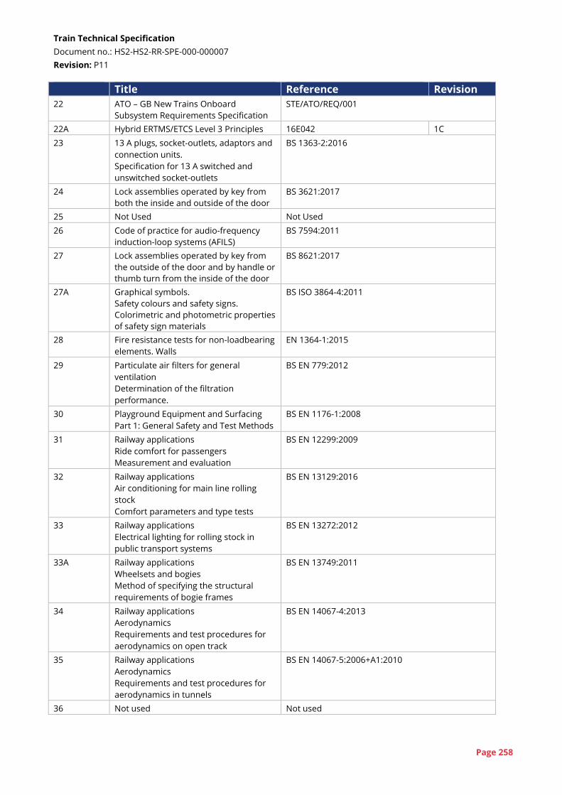
Train Technical Specification
Document no.: HS2-HS2-RR-SPE-000-000007
Revision: P11
Page 258
Title Reference Revision
22 ATO – GB New Trains Onboard
Subsystem Requirements Specification
STE/ATO/REQ/001
22A Hybrid ERTMS/ETCS Level 3 Principles 16E042 1C
23 13 A plugs, socket-outlets, adaptors and
connection units.
Specification for 13 A switched and
unswitched socket-outlets
BS 1363-2:2016
24 Lock assemblies operated by key from
both the inside and outside of the door
BS 3621:2017
25 Not Used Not Used
26 Code of practice for audio-frequency
induction-loop systems (AFILS)
BS 7594:2011
27 Lock assemblies operated by key from
the outside of the door and by handle or
thumb turn from the inside of the door
BS 8621:2017
27A Graphical symbols.
Safety colours and safety signs.
Colorimetric and photometric properties
of safety sign materials
BS ISO 3864-4:2011
28 Fire resistance tests for non-loadbearing
elements. Walls
EN 1364-1:2015
29 Particulate air filters for general
ventilation
Determination of the filtration
performance.
BS EN 779:2012
30 Playground Equipment and Surfacing
Part 1: General Safety and Test Methods
BS EN 1176-1:2008
31 Railway applications
Ride comfort for passengers
Measurement and evaluation
BS EN 12299:2009
32 Railway applications
Air conditioning for main line rolling
stock
Comfort parameters and type tests
BS EN 13129:2016
33 Railway applications
Electrical lighting for rolling stock in
public transport systems
BS EN 13272:2012
33A Railway applications
Wheelsets and bogies
Method of specifying the structural
requirements of bogie frames
BS EN 13749:2011
34 Railway applications
Aerodynamics
Requirements and test procedures for
aerodynamics on open track
BS EN 14067-4:2013
35 Railway applications
Aerodynamics
Requirements and test procedures for
aerodynamics in tunnels
BS EN 14067-5:2006+A1:2010
36 Not used Not used
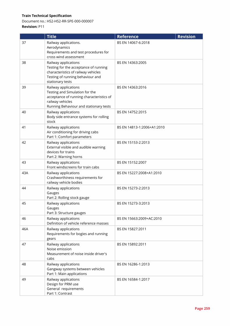
Train Technical Specification
Document no.: HS2-HS2-RR-SPE-000-000007
Revision: P11
Page 259
Title Reference Revision
37 Railway applications.
Aerodynamics
Requirements and test procedures for
cross wind assessment
BS EN 14067-6:2018
38 Railway applications
Testing for the acceptance of running
characteristics of railway vehicles
Testing of running behaviour and
stationary tests
BS EN 14363:2005
39 Railway applications
Testing and Simulation for the
acceptance of running characteristics of
railway vehicles
Running Behaviour and stationary tests
BS EN 14363:2016
40 Railway applications
Body side entrance systems for rolling
stock
BS EN 14752:2015
41 Railway applications
Air conditioning for driving cabs
Part 1: Comfort parameters
BS EN 14813-1:2006+A1:2010
42 Railway applications
External visible and audible warning
devices for trains
Part 2: Warning horns
BS EN 15153-2:2013
43 Railway applications
Front windscreens for train cabs
BS EN 15152:2007
43A Railway applications
Crashworthiness requirements for
railway vehicle bodies
BS EN 15227:2008+A1:2010
44 Railway applications
Gauges
Part 2: Rolling stock gauge
BS EN 15273-2:2013
45 Railway applications
Gauges
Part 3: Structure gauges
BS EN 15273-3:2013
46 Railway applications
Definition of vehicle reference masses
BS EN 15663:2009+AC:2010
46A Railway applications
Requirements for bogies and running
gears
BS EN 15827:2011
47 Railway applications
Noise emission
Measurement of noise inside driver's
cabs
BS EN 15892:2011
48 Railway applications
Gangway systems between vehicles
Part 1: Main applications
BS EN 16286-1:2013
49 Railway applications
Design for PRM use
General requirements
Part 1: Contrast
BS EN 16584-1:2017
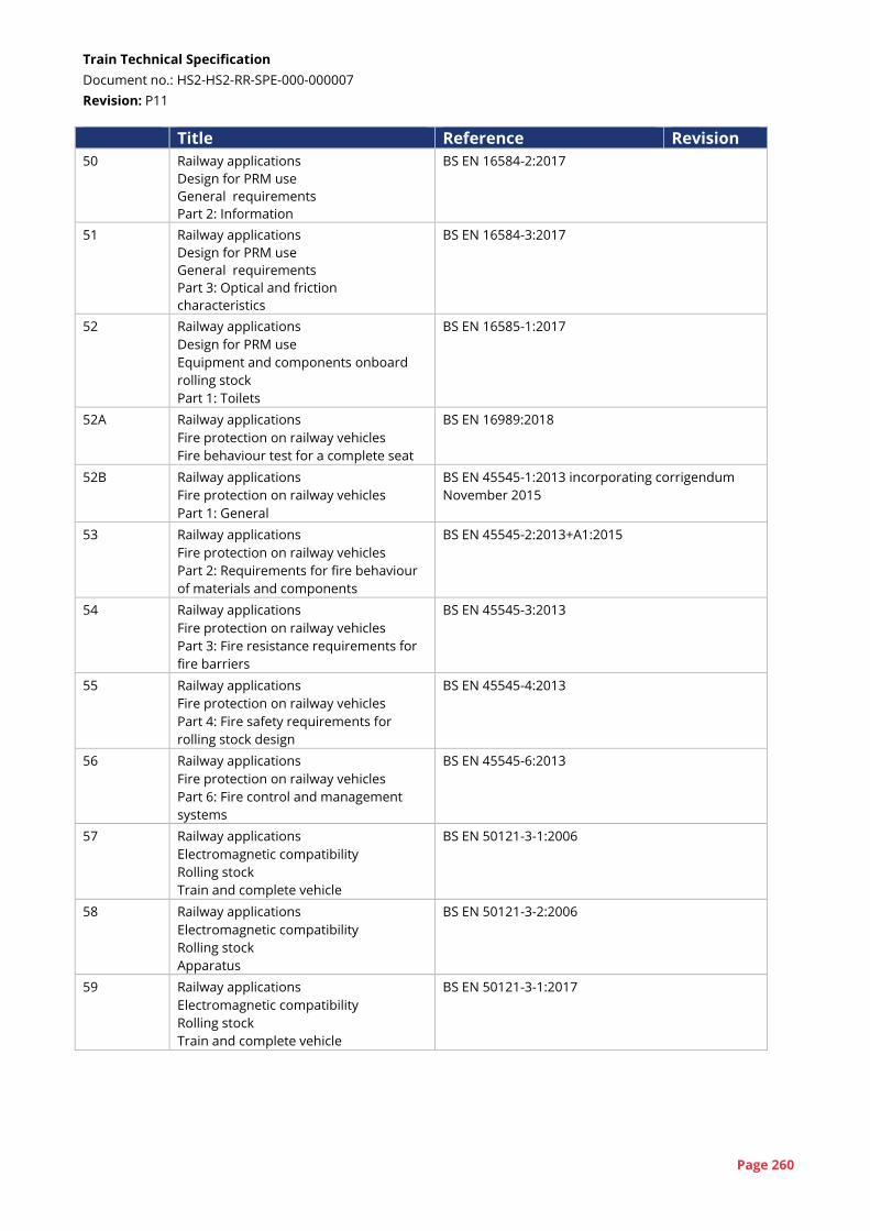
Train Technical Specification
Document no.: HS2-HS2-RR-SPE-000-000007
Revision: P11
Page 260
Title Reference Revision
50 Railway applications
Design for PRM use
General requirements
Part 2: Information
BS EN 16584-2:2017
51 Railway applications
Design for PRM use
General requirements
Part 3: Optical and friction
characteristics
BS EN 16584-3:2017
52 Railway applications
Design for PRM use
Equipment and components onboard
rolling stock
Part 1: Toilets
BS EN 16585-1:2017
52A Railway applications
Fire protection on railway vehicles
Fire behaviour test for a complete seat
BS EN 16989:2018
52B Railway applications
Fire protection on railway vehicles
Part 1: General
BS EN 45545-1:2013 incorporating corrigendum
November 2015
53 Railway applications
Fire protection on railway vehicles
Part 2: Requirements for fire behaviour
of materials and components
BS EN 45545-2:2013+A1:2015
54 Railway applications
Fire protection on railway vehicles
Part 3: Fire resistance requirements for
fire barriers
BS EN 45545-3:2013
55 Railway applications
Fire protection on railway vehicles
Part 4: Fire safety requirements for
rolling stock design
BS EN 45545-4:2013
56 Railway applications
Fire protection on railway vehicles
Part 6: Fire control and management
systems
BS EN 45545-6:2013
57 Railway applications
Electromagnetic compatibility
Rolling stock
Train and complete vehicle
BS EN 50121-3-1:2006
58 Railway applications
Electromagnetic compatibility
Rolling stock
Apparatus
BS EN 50121-3-2:2006
59 Railway applications
Electromagnetic compatibility
Rolling stock
Train and complete vehicle
BS EN 50121-3-1:2017
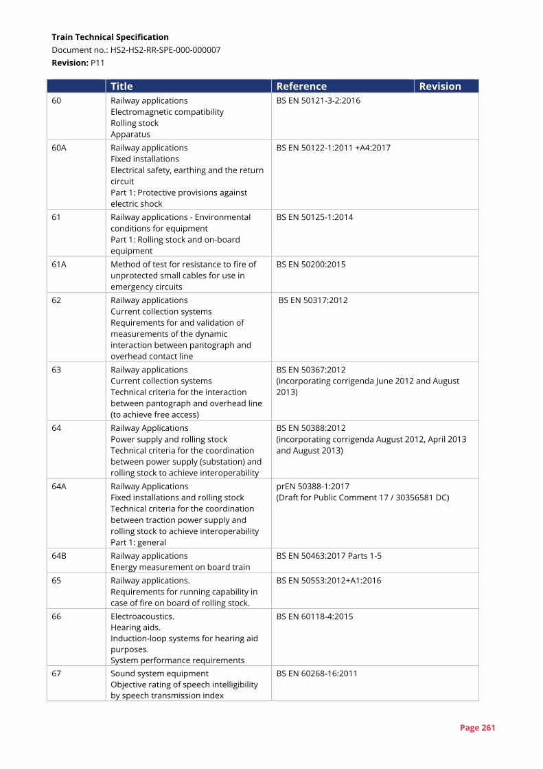
Train Technical Specification
Document no.: HS2-HS2-RR-SPE-000-000007
Revision: P11
Page 261
Title Reference Revision
60 Railway applications
Electromagnetic compatibility
Rolling stock
Apparatus
BS EN 50121-3-2:2016
60A Railway applications
Fixed installations
Electrical safety, earthing and the return
circuit
Part 1: Protective provisions against
electric shock
BS EN 50122-1:2011 +A4:2017
61 Railway applications - Environmental
conditions for equipment
Part 1: Rolling stock and on-board
equipment
BS EN 50125-1:2014
61A Method of test for resistance to fire of
unprotected small cables for use in
emergency circuits
BS EN 50200:2015
62 Railway applications
Current collection systems
Requirements for and validation of
measurements of the dynamic
interaction between pantograph and
overhead contact line
BS EN 50317:2012
63 Railway applications
Current collection systems
Technical criteria for the interaction
between pantograph and overhead line
(to achieve free access)
BS EN 50367:2012
(incorporating corrigenda June 2012 and August
2013)
64 Railway Applications
Power supply and rolling stock
Technical criteria for the coordination
between power supply (substation) and
rolling stock to achieve interoperability
BS EN 50388:2012
(incorporating corrigenda August 2012, April 2013
and August 2013)
64A Railway Applications
Fixed installations and rolling stock
Technical criteria for the coordination
between traction power supply and
rolling stock to achieve interoperability
Part 1: general
prEN 50388-1:2017
(Draft for Public Comment 17 / 30356581 DC)
64B Railway applications
Energy measurement on board train
BS EN 50463:2017 Parts 1-5
65 Railway applications.
Requirements for running capability in
case of fire on board of rolling stock.
BS EN 50553:2012+A1:2016
66 Electroacoustics.
Hearing aids.
Induction-loop systems for hearing aid
purposes.
System performance requirements
BS EN 60118-4:2015
67 Sound system equipment
Objective rating of speech intelligibility
by speech transmission index
BS EN 60268-16:2011
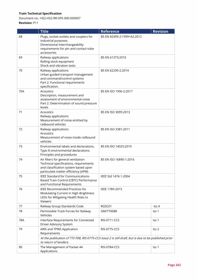
Train Technical Specification
Document no.: HS2-HS2-RR-SPE-000-000007
Revision: P11
Page 262
Title Reference Revision
68 Plugs, socket-outlets and couplers for
industrial purposes.
Dimensional interchangeability
requirements for pin and contact-tube
accessories
BS EN 60309-2:1999+A2:2012
69 Railway applications
Rolling stock equipment
Shock and vibration tests
BS EN 61373:2010
70 Railway applications
Urban guided transport management
and command/control systems
Part 2: Functional requirements
specification.
BS EN 62290-2:2014
70A Acoustics
Description, measurement and
assessment of environmental noise
Part 2: Determination of sound pressure
levels
BS EN ISO 1996-2:2017
71 Acoustics
Railway applications
Measurement of noise emitted by
railbound vehicles
BS EN ISO 3095:2013
72 Railway applications
Acoustics
Measurement of noise inside railbound
vehicles
BS EN ISO 3381:2011
73 Environmental labels and declarations.
Type III environmental declarations.
Principles and procedures
BS EN ISO 14025:2010
74 Air filters for general ventilation
Technical specifications, requirements
and classification system based upon
particulate matter efficiency (ePM)
BS EN ISO 16890-1:2016
75 IEEE Standard for Communications-
Based Train Control (CBTC) Performance
and Functional Requirements
IEEE Std 1474.1-2004
76 IEEE Recommended Practices for
Modulating Current in High-Brightness
LEDs for Mitigating Health Risks to
Viewers
IEEE 1789-2015
77 Railway Group Standards Code RGSC01 Iss 4
78 Permissible Track Forces for Railway
Vehicles
GM/TT0088 Iss 1
78A Interface Requirements for Connected
Driver Advisory System
RIS-0711-CCS Iss 1
79
AWS and TPWS Application
Requirements
RIS-0775-CCS Iss 2
At the publication of TTS P08, RIS-0775-CCS issue 2 is still draft, but is due to be published prior
to return of tenders.
80 The Management of Packet 44
Applications
RIS-0784-CCS Iss 1
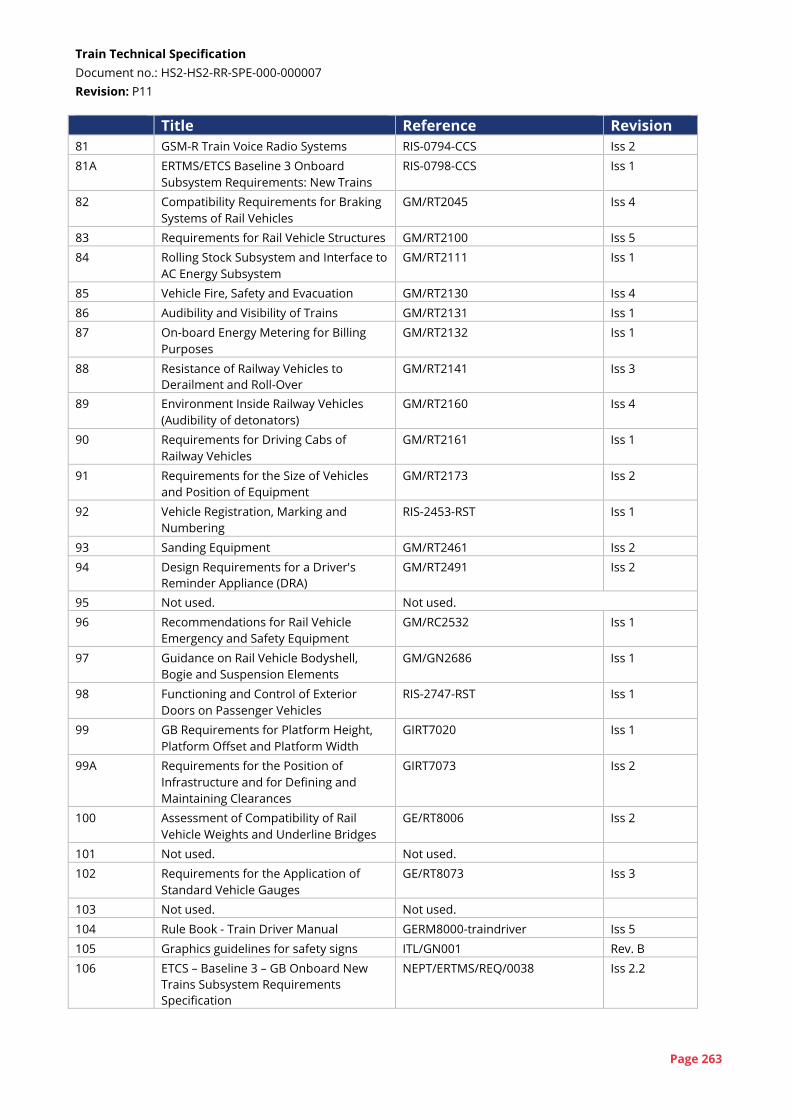
Train Technical Specification
Document no.: HS2-HS2-RR-SPE-000-000007
Revision: P11
Page 263
Title Reference Revision
81 GSM-R Train Voice Radio Systems RIS-0794-CCS Iss 2
81A ERTMS/ETCS Baseline 3 Onboard
Subsystem Requirements: New Trains
RIS-0798-CCS Iss 1
82 Compatibility Requirements for Braking
Systems of Rail Vehicles
GM/RT2045 Iss 4
83 Requirements for Rail Vehicle Structures GM/RT2100 Iss 5
84 Rolling Stock Subsystem and Interface to
AC Energy Subsystem
GM/RT2111 Iss 1
85 Vehicle Fire, Safety and Evacuation GM/RT2130 Iss 4
86 Audibility and Visibility of Trains GM/RT2131 Iss 1
87 On-board Energy Metering for Billing
Purposes
GM/RT2132 Iss 1
88 Resistance of Railway Vehicles to
Derailment and Roll-Over
GM/RT2141 Iss 3
89 Environment Inside Railway Vehicles
(Audibility of detonators)
GM/RT2160 Iss 4
90 Requirements for Driving Cabs of
Railway Vehicles
GM/RT2161 Iss 1
91 Requirements for the Size of Vehicles
and Position of Equipment
GM/RT2173 Iss 2
92 Vehicle Registration, Marking and
Numbering
RIS-2453-RST Iss 1
93 Sanding Equipment GM/RT2461 Iss 2
94 Design Requirements for a Driver's
Reminder Appliance (DRA)
GM/RT2491 Iss 2
95 Not used. Not used.
96 Recommendations for Rail Vehicle
Emergency and Safety Equipment
GM/RC2532 Iss 1
97 Guidance on Rail Vehicle Bodyshell,
Bogie and Suspension Elements
GM/GN2686 Iss 1
98 Functioning and Control of Exterior
Doors on Passenger Vehicles
RIS-2747-RST Iss 1
99 GB Requirements for Platform Height,
Platform Offset and Platform Width
GIRT7020 Iss 1
99A Requirements for the Position of
Infrastructure and for Defining and
Maintaining Clearances
GIRT7073 Iss 2
100 Assessment of Compatibility of Rail
Vehicle Weights and Underline Bridges
GE/RT8006 Iss 2
101 Not used. Not used.
102 Requirements for the Application of
Standard Vehicle Gauges
GE/RT8073 Iss 3
103 Not used. Not used.
104 Rule Book - Train Driver Manual GERM8000-traindriver Iss 5
105 Graphics guidelines for safety signs ITL/GN001 Rev. B
106 ETCS – Baseline 3 – GB Onboard New
Trains Subsystem Requirements
Specification
NEPT/ERTMS/REQ/0038 Iss 2.2
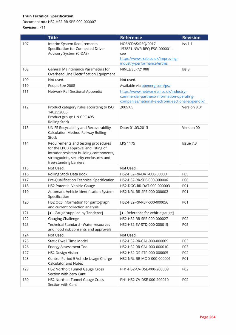
Train Technical Specification
Document no.: HS2-HS2-RR-SPE-000-000007
Revision: P11
Page 264
Title Reference Revision
107 Interim System Requirements
Specification for Connected Driver
Advisory System (C-DAS)
NOS/CDAS/REQ/0017
153821-NWR-REQ-ESG-000001 –
see
https://www.rssb.co.uk/improving-
industry-performance/ertms
Iss 1.1
108 General Maintenance Parameters for
Overhead Line Electrification Equipment
NR/L2/ELP/21088 Iss 3
109 Not used. Not used.
110 PeopleSize 2008 Available via openerg.com/psz
111 Network Rail Sectional Appendix https://www.networkrail.co.uk/industry-
commercial-partners/information-operating-
companies/national-electronic-sectional-appendix/
112 Product category rules according to ISO
14025:2006
Product group: UN CPC 495
Rolling Stock
2009:05 Version 3.01
113 UNIFE Recyclability and Recoverability
Calculation Method Railway Rolling
Stock
Date: 01.03.2013 Version 00
114 Requirements and testing procedures
for the LPCB approval and listing of
intruder resistant building components,
strongpoints, security enclosures and
free-standing barriers
LPS 1175 Issue 7.3
115 Not Used. Not Used.
116 Rolling Stock Data Book HS2-HS2-RR-DAT-000-000001 P05
117 Pre-Qualification Technical Specification HS2-HS2-RR-SPE-000-000006 P06
118 HS2 Potential Vehicle Gauge HS2-DGG-RR-DAT-000-000003 P01
119 Automatic Vehicle Identification System
Specification
HS2-NRL-RR-SPE-000-000002 P01
120 HS2 OCS information for pantograph
and current collection analysis
HS2-HS2-RR-REP-000-000056 P01
121 [● - Gauge supplied by Tenderer] [● - Reference for vehicle gauge]
122 Gauging Challenge HS2-HS2-RR-SPE-000-000027 P02
123 Technical Standard - Water resources
and flood risk consents and approvals
HS2-HS2-EV-STD-000-000015 P05
124 Not Used. Not Used.
125 Static Dwell Time Model HS2-HS2-RR-CAL-000-000009 P03
126 Energy Assessment Tool HS2-HS2-RR-CAL-000-000010 P03
127 HS2 Design Vision HS2-HS2-DS-STR-000-000005 P02
128 Control Period 5 Vehicle Usage Charge
Calculator and Notes
HS2-NRL-RR-MOD-000-000001 P01
129 HS2 Northolt Tunnel Gauge Cross
Section with Zero Cant
PH1-HS2-CV-DSE-000-200009 P02
130 HS2 Northolt Tunnel Gauge Cross
Section with Cant
PH1-HS2-CV-DSE-000-200010 P02