traffic signal mast arm baseplate connections are
TRANSCRIPT

i
Technical Report Documentation Page
1. Report No. FHWA/TX-06/5-4178-01-3
2. Government Accession No.
3. Recipient’s Catalog No.
5. Report Date September 2005
4. Title and Subtitle UIT Application During Fabrication
6. Performing Organization Code 7. Author(s)
Amanda H. Palmatier, Karl H. Frank 8. Performing Organization Report No.
5-4178-01-3
10. Work Unit No. (TRAIS) 9. Performing Organization Name and Address Center for Transportation Research The University of Texas at Austin 3208 Red River, Suite 200 Austin, TX 78705-2650
11. Contract or Grant No. 5-4178-01
13. Type of Report and Period Covered Technical Report (09/01/03 - 08/31/05)
12. Sponsoring Agency Name and Address Texas Department of Transportation Research and Technology Implementation Office P.O. Box 5080 Austin, TX 78763-5080
14. Sponsoring Agency Code
15. Supplementary Notes Project performed in cooperation with the Texas Department of Transportation and the Federal Highway Administration.
16. Abstract Traffic signal mast arm baseplate connections are particularly susceptible to fatigue. The
top of traffic signal mast arm welds experience fluctuating tensile stresses when wind and traffic gust loads cause the mast arm to oscillate. It has been postulated that UIT application to mast arm weld toes during the fabrication process will delay fatigue crack initiation. Successful UIT application during the fabrication process will extend fatigue lives of traffic signal mast arm welds in the field. Since mast arm welds are the weakest spot in the traffic signal structure, increased weld life translates into increased traffic signal life. Previous research claims that UIT is light, quiet, and easy to learn. Critical areas under scrutiny during UIT application at the fabrication plant are: time lost due to training workers, time lost during the UIT application, and efficiency of the treated poles. This report investigates the first two issues by documenting the application of UIT to fabricated mast arms at the TransAmerican Power Products facility.
17. Key Words
Traffic, signal, mast, arms, baseplate, UIT, TransAmerican Power Products, Ferguson
18. Distribution Statement No restrictions. This document is available to the public through the National Technical Information Service, Springfield, Virginia 22161; www.ntis.gov.
19. Security Classif. (of report) Unclassified
20. Security Classif. (of this page) Unclassified
21. No. of pages 38
22. Price
Form DOT F 1700.7 (8-72) Reproduction of completed page authorized

ii

iii
UIT Application During Fabrication Amanda A. Palmatier Karl H. Frank CTR Research Report: 5-4178-01-3 Report Date: September 2005 Research Project: 5-4178-01 Research Project Title: Ultrasonic Impact Treatment (UIT) for Traffic Signal Structure Fatigue Details Sponsoring Agency: Texas Department of Transportation Performing Agency: Center for Transportation Research at The University of Texas at Austin Project performed in cooperation with the Texas Department of Transportation and the Federal Highway Administration.
FERGUSON STRUCTURAL ENGINEERING LAB
The University of Texas at Austin

iv
Center for Transportation Research The University of Texas at Austin 3208 Red River Austin, TX 78705 www.utexas.edu/research/ctr Copyright (c) 2006 Center for Transportation Research The University of Texas at Austin All rights reserved Printed in the United States of America

v
Disclaimers Author's Disclaimer: The contents of this report reflect the views of the authors, who
are responsible for the facts and the accuracy of the data presented herein. The contents do not necessarily reflect the official view or policies of the Federal Highway Administration or the Texas Department of Transportation (TxDOT). This report does not constitute a standard, specification, or regulation.
Patent Disclaimer: There was no invention or discovery conceived or first actually reduced to practice in the course of or under this contract, including any art, method, process, machine manufacture, design or composition of matter, or any new useful improvement thereof, or any variety of plant, which is or may be patentable under the patent laws of the United States of America or any foreign country.
Notice: The United States Government and the State of Texas do not endorse products or manufacturers. If trade or manufacturers' names appear herein, it is solely because they are considered essential to the object of this report.
Engineering Disclaimer NOT INTENDED FOR CONSTRUCTION, BIDDING, OR PERMIT PURPOSES.
Karl H. Frank, P.E., Texas No. 48953
Research Supervisor

vi
Acknowledgments We greatly appreciate the financial support from the Texas Department of Transportation
that made this project possible. The support of the implementation director, Scott Walton (BRG) is also very much appreciated. The help and technical expertise of Blake Stasney, Dennis Fillip and Mike Bell of the Ferguson Laboratory staff contributed to the success of the research.

vii
Table of Contents INTRODUCTION .......................................................................................................................................................1
TRAINING SESSION.................................................................................................................................................3
AFTERNOON FABRICATION YARD UIT APPLICATION TRAINING..........................................................5 TEST SETUP ...............................................................................................................................................................5 UIT APPLICATION DEMONSTRATION.........................................................................................................................8 INSPECTION BY A TXDOT INSPECTOR.....................................................................................................................12 REPAIR OF GALVANIZING ........................................................................................................................................14 REMOVAL OF MAST ARM FROM FIXED TESTING STAND .........................................................................................16 APPLIED ULTRASONICS TECHNICIAN TREATMENT TIMES .......................................................................................17
APPLICATION OF UIT BY TRAINED EMPLOYEES.......................................................................................19 TRANSAMERICAN EMPLOYEE’S UIT APPLICATION TIMES ......................................................................................20
DISCUSSION.............................................................................................................................................................23 TRAINED APPLIED ULTRASONICS TECHNICIAN TREATMENT VS TRAINED TRANSAMERICAN EMPLOYEE TREATMENT ............................................................................................................................................................23 UIT APPLICATION CONCERNS .................................................................................................................................23
REFERENCES ..........................................................................................................................................................25

viii

ix
List of Figures FIGURE 1 STOCKPILED MAST ARMS AT THE TRANSAMERICAN FABRICATION YARD ....................................................5 FIGURE 2 MAST ARM BEING CONNECTED TO FIXED TESTING STAND ...........................................................................6 FIGURE 3 CRANE MOVING THE 500-POUND CIRCULAR WEIGHT TO THE MAST ARM END ............................................7 FIGURE 4 PLACING THE 500-POUND CIRCULAR WEIGHT ON THE END OF THE MAST ARM............................................7 FIGURE 5 MAST ARM WITH 6-INCH EXTENSION AT THE END FOR THE 500-POUND CIRCULAR WEIGHT........................8 FIGURE 6 ENTIRE LOADED AND FIXED MAST ARM UIT SETUP .....................................................................................8 FIGURE 7 UIT GENERATOR (BLUE BOX ON LEFT) AND WATER PUMP (RED BOX ON RIGHT)........................................9 FIGURE 8 FRONT VIEW OF THE UIT TOOL, POWER GENERATOR, AND UIT GENERATOR...............................................9 FIGURE 9 APPLICATION OF UIT TO A MAST ARM WELD TOE......................................................................................10 FIGURE 10 MAST ARM-BASEPLATE WELD CONNECTION BEFORE UIT APPLICATION .................................................11 FIGURE 11 COMPLETED MAST ARM WELD TOE UIT...................................................................................................11 FIGURE 12 APPLICATION OF UIT TO BASEPLATE WELD TOE.......................................................................................12 FIGURE 13 REMOVAL OF GALVANIZATION WITH A WIRE BRUSH ................................................................................13 FIGURE 14 MEASUREMENT OF UIT APPLICATION GROOVE USING AN UNDERCUT MEASURING DEVICE .....................14 FIGURE 15 MEASUREMENT OF UIT APPLICATION GROOVE BY ROLLING A 3 MM DIAMETER PIN FROM THE UIT TOOL
IN THE UIT APPLICATION GROOVE .....................................................................................................................14 FIGURE 16 APPLICATION OF ZINC-RICH PAINT............................................................................................................15 FIGURE 17 DRYING ZINC-RICH PAINT .........................................................................................................................15 FIGURE 18 MAST ARM WELD AFTER COMPLETION.....................................................................................................16 FIGURE 19 EMPLOYEE APPLYING UIT TO A TEST PLATE WELD ..................................................................................19 FIGURE 20 EMPLOYEE’S FIRST UIT APPLICATION TO A MAST ARM WELD .................................................................20

x

xi
List of Tables TABLE 1 DESCRIPTION OF PHASES OF UIT APPLICATION ............................................................................................17 TABLE 2 EMPLOYEE’S FIRST UIT APPLICATION TO A MAST ARM WELD TIMES .........................................................20

xii

1
INTRODUCTION
Traffic signal mast arm to baseplate connections are particularly susceptible to fatigue. The weld at the top of traffic signal mast arms experience fluctuating tensile stresses when wind and traffic gust loads cause the mast arm to oscillate. It has been postulated that UIT application to mast arm weld toes during the fabrication process will delay fatigue crack initiation [1]. Successful UIT application during the fabrication process will extend fatigue lives of traffic signal mast arm welds in the field. Since mast arm welds are the weakest spot in the traffic signal structure [1], increased weld life translates into increased traffic signal structure life.
UIT must be applied after hot-dip galvanization, since temperatures above 300oC have
proven to undo the benefits of UIT, probably because extreme heat relaxes the beneficial compressive stresses induced by UIT [2, 6]. Hence, UIT is the final step of the fabrication process at the fabrication plant. Galvanization removed during UIT application is repaired with a zinc-rich paint, which has no effect on the UIT. [2, 3].
Previous research claims that UIT is light, quiet, and easy to learn [3, 4, 5, 6, 7, 8]. Critical areas under scrutiny during UIT application at the fabrication plant are: time lost due to training workers, time lost during the UIT application, and fatigue performance of the treated poles. Proprietary tests performed for TransAmerican Power Products indicated that UIT treatment significantly improved the fatigue performance of their traffic signal structures. Therefore, this report investigates only the first two issues by documenting the application of UIT to fabricated mast arms at the TransAmerican Power Products facility.

2

3
TRAINING SESSION
UIT training took place at the TransAmerican Power Products, Inc. fabrication yard, located at 2427 Kelly Lane, Houston, TX 77066. The observed training began on October 12, 2004. UIT training covers application technique and basic theory behind UIT. UIT training was lead by a trained Applied Ultrasonics technician. Applied Ultrasonics is currently the only UIT vendor in the US.
During the morning training of October 12, 2004, the Applied Ultrasonics technician met
with the Vice President of TransAmerican, TransAmerican’s Quality Control person, two TxDOT inspectors, and the author. The two workers that would actually perform the treatment were not present at this morning presentation. Since everyone in the group, with the exception of the Quality Control person, was familiar with UIT, the Applied Ultrasonics technician presented a shortened version of the UIT background information presentation, which only lasted one and a half hours. The information presentation for a group that is not familiar with the process usually lasts the entire morning of a daylong UIT training session.
The presentation introduced the concept of increasing fatigue life, using UIT, showed the
equipment, proper application settings and techniques, and stressed that already cracked materials cannot be treated. The TransAmerican Quality Control person, the only person at the presentation not familiar with UIT, asked many questions, and the Applied Ultrasonics technician had no problem answering all the questions. The TransAmerican Quality Control person has an extensive background on other weld fatigue life improvements, and after the presentation he understood UIT to be a process similar to shot peening.

4
5
AFTERNOON FABRICATION YARD UIT APPLICATION TRAINING
The UIT application training took place in the TransAmerican yard over a few days. The first day is documented in this section.
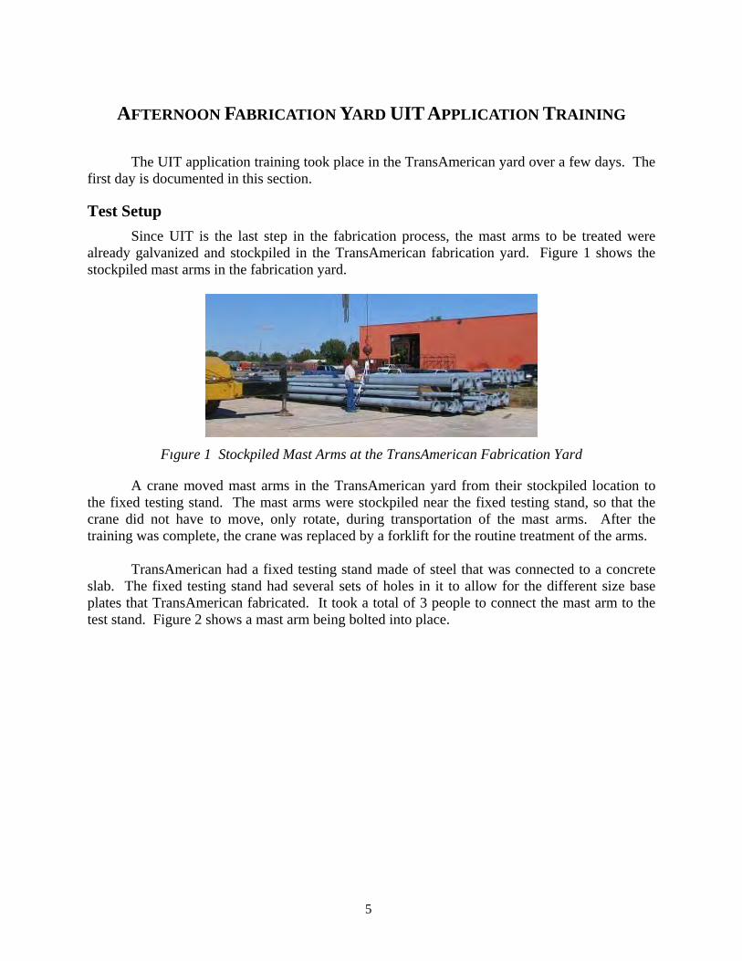
Test Setup Since UIT is the last step in the fabrication process, the mast arms to be treated were
already galvanized and stockpiled in the TransAmerican fabrication yard. Figure 1 shows the stockpiled mast arms in the fabrication yard.
Fıgure 1 Stockpiled Mast Arms at the TransAmerican Fabrication Yard
A crane moved mast arms in the TransAmerican yard from their stockpiled location to the fixed testing stand. The mast arms were stockpiled near the fixed testing stand, so that the crane did not have to move, only rotate, during transportation of the mast arms. After the training was complete, the crane was replaced by a forklift for the routine treatment of the arms.
TransAmerican had a fixed testing stand made of steel that was connected to a concrete
slab. The fixed testing stand had several sets of holes in it to allow for the different size base plates that TransAmerican fabricated. It took a total of 3 people to connect the mast arm to the test stand. Figure 2 shows a mast arm being bolted into place.

6
Fıgure 2 Mast Arm Being Connected to Fixed Testing Stand
Previous research by Koenigs shows that UIT application is most effective when applied under an imposed stress of 16.5 ksi at the treated weld toe [1]. The mast arms at TransAmerican have UIT applied under a nominal 16.5 ksi bending stress to simulate the stress in the arm under static service loading. There are two sets of design standards for TxDOT’s cantilever traffic signal structures: Structures that are designed for 100 mph winds, and structures that are designed for 80 mph winds. TxDOT inspectors used the standards for structures designed for 100 mph winds when determining the load to place at the mast arm end that would induce a 16.5 ksi stress at the weld toe of a 20 foot mast arm. A 500-pound load was applied to the end of all mast arms before UIT application at the TransAmerican fabrication yard to produce the nominal 16.5 ksi stress at the weld toe. To simplify the application procedure, the same weight was used for all mast arms.
After the mast arm was bolted to the fixed testing stand it was loaded with a 500-pound
circular weight, as shown in Figure 3 and Figure 4. Figure 3 shows the crane as it moved a 500-pound circular weight to the end of the mast arm. Figure 4 shows personnel securing the 500-pound weight in place. Figure 5 shows a close-up of the 6 inch tenon at the end of the mast arm that was used to support the 500-pound circular weight during UIT application.

7
Fıgure 3 Crane Moving the 500-Pound Circular Weight to the Mast Arm End
Fıgure 4 Placing the 500-Pound Circular Weight on the End of the Mast Arm

8
Fıgure 5 Mast Arm with 6-Inch Tenon at the End
Figure 6 shows the entire UIT application set-up in the TransAmerican fabrication yard prior to UIT application.
Figure 6 Entire Loaded and Fixed Mast Arm UIT Setup
UIT Application Demonstration UIT application began after the mast arm was secured in the loading setup and loaded
with the 500-pound weight. The Applied Ultrasonics technician demonstrated the UIT application procedure by applying UIT to the TransAmerican mast arm. The TransAmerican workers who were being trained observed the example application.
First, the power generator was turned on. The power generator supplied power to the
UIT generator. Next, the water pump was turned on to cool the UIT generator. The UIT generator produces the ultrasonic oscillations that are utilized by the UIT tool to treat the steel weld. Then the UIT generator was turned on to maximum power, which corresponded to 80 volts. The UIT tool used 10 amps, so the power applied during UIT application was 800 watts. The UIT generator was set at maximum power for all mast arm applications. Figure 7 shows the UIT generator and the water pump. Figure 8 shows the UIT generator, the UIT tool, and the power generator.

9
Figure 7 UIT Generator (Blue Box on Left) and Water Pump (Red Box on Right)
Figure 8 Front View of the UIT Tool, Power Generator, and UIT Generator
The technician applied UIT to both toes of the mast arm-base plate weld. The Applied Ultrasonics technician expressed that it is irrelevant which weld toe is treated first. Both weld toes were treated with UIT following the same procedure. UIT was applied to the mast arm weld toe with the multi-pin UIT tool held at a 45° angle from the mast arm. The angle that the UIT tool is held against the weld toe during application can range from 30° to 60°, but an effort to keep the tool at 45° to the weld toe should be made. The UIT application followed the weld toe so as to create a smoother transition from the weld to the mast arm or base plate. A maximum of four passes was made with the UIT tool. UIT with a 1/8 inch diameter pin should create about a 1/8 inch impression at the weld toe. In general, the groove created by UIT is expected to be about the size of the treatment pin.

10
The UIT tool used during application had a multi-pin head on the tool, with two 1/8 inch pins installed. Applied Ultrasonics has found that two pins perform better than three or four 1/8 inch diameter pins for application to 10 inch diameter mast arm weld. The reason that two pins give superior UIT application is that the small diameter of the mast arm prevents three or more pins from coming into contact during application. A flat plate, for example, would probably get superior UIT application from three or four 1/8 inch diameter pins in the multi-pin tool because all of the pins would be able to contact the steel during treatment. Figure 9 shows UIT application.
Figure 9 Application of UIT to a Mast Arm Weld Toe
The UIT was applied with a steady, yet light, pressure on the UIT tool. The application technique did not require a hard push. The UIT tool was moved over the length of the mast arm weld toe to be treated. The 6.6 pound weight of the tool and the action of the tool itself created the necessary contact force. The length of the UIT application along the mast arm weld toe extended 90° in each direction from the top vertical of the mast arm. Hence, the entire top 180° of the mast arm weld toes was treated with UIT. Since the mast arm had a 10 inch diameter, the mast arm had a weld toe circumference of 31.4 inches. The topmost 15.7 inches of the 31.5 inch mast arm weld was peened with UIT. The bottom 180o of the mast arm does not need UIT application because previous tests indicate that fatigue cracking does not occur where the mast arm is in compression, namely, the bottom of the mast arm [1].
Figure 10 shows the mast arm-baseplate connection before UIT application. Figure 11
shows a 180o application of UIT to the weld toe on the arm. Notice in Figure 11 that the treated area is shiny due to the galvanization flaking off during treatment which revealed the un-galvanized steel underneath. In Figure 11 the groove produced by the 1/8 inch diameter pins of the multi-pin UIT tool is also visible. Figure 12 shows application of UIT to the baseplate weld toe.

11
Figure 10 Mast Arm-Baseplate Weld Connection Before UIT Application
Figure 11 Completed Mast Arm Weld Toe UIT

12
Figure 12 Application of UIT to Baseplate Weld Toe
Inspection by a TxDOT Inspector After the example UIT application by the trained technician, a TxDOT inspector
inspected the groove produced by UIT application. One hindrance to perfect UIT application is when existing galvanization on the mast arm weld toe does not flake off from UIT application, or flakes off and then gets between the UIT tool pins and the mast arm weld metal. Pieces of galvanization can result in a barrier between the UIT tool and the metal to be treated. According to the Applied Ultrasonics technician, during past UIT applications, pieces of galvanization have prevented proper impact of the weld metal by the UIT tool. If either the galvanization does not flake off during treatment, or galvanization that has flaked off gets between the UIT tool and the area of treatment, gaps in proper UIT application will occur. The UIT application area must be cleared of any remaining galvanization after UIT application for inspection for incomplete treatment. The trained technician suggested using a screwdriver to remove galvanization after UIT application, if a screwdriver is available. Oil cannot be used to remove galvanization after UIT application, because oil will interfere with application of the zinc-rich paint to repair the galvanizing area after UIT application. TxDOT inspectors recommend using a wire brush for galvanization removal after UIT application. Figure 13 shows galvanization being removed with a wire brush.

13
Figure 13 Removal of Galvanization with a Wire Brush
After all galvanization was removed from the UIT application area, and the UIT application was complete, the UIT application depth was measured. Proper UIT application with 3 mm diameter pins in a multi-pin UIT tool usually produces a 1/8” (3 mm) diameter groove along the treated weld toe. The width of the UIT application groove and the maximum depth of the UIT application groove were difficult to measure. The depth of the UIT application groove can be measured either with a weld undercut measuring device, or by rolling a single 3 mm diameter pin from the UIT tool in the UIT application groove. Rolling the 3 mm diameter pin from the UIT tool in the UIT application groove is a good check of the UIT application groove’s depth and width when more sophisticated tools are not available. Figure 14 shows the measurement of the UIT application groove using an undercut measuring device. Figure 15 shows a 3 mm diameter pin from the UIT tool rolled in the UIT application groove.

14
Figure 14 Measurement of UIT Application Groove Using an Undercut Measuring Device
Figure 15 Measurement of UIT Application Groove by Rolling a 3 mm Diameter Pin from the
UIT Tool in the UIT Application Groove
Repair of Galvanizing After satisfactory inspection of the UIT application by a TxDOT inspector, a zinc-rich
paint repair was applied in two coats by the TxDOT inspector. The first coat was allowed to dry before the second coat was applied. The zinc-rich paint used at the TransAmerican fabrication yard by TxDOT inspectors was Rust-oleum Cold Galvanizing compound, which contained 93%

15
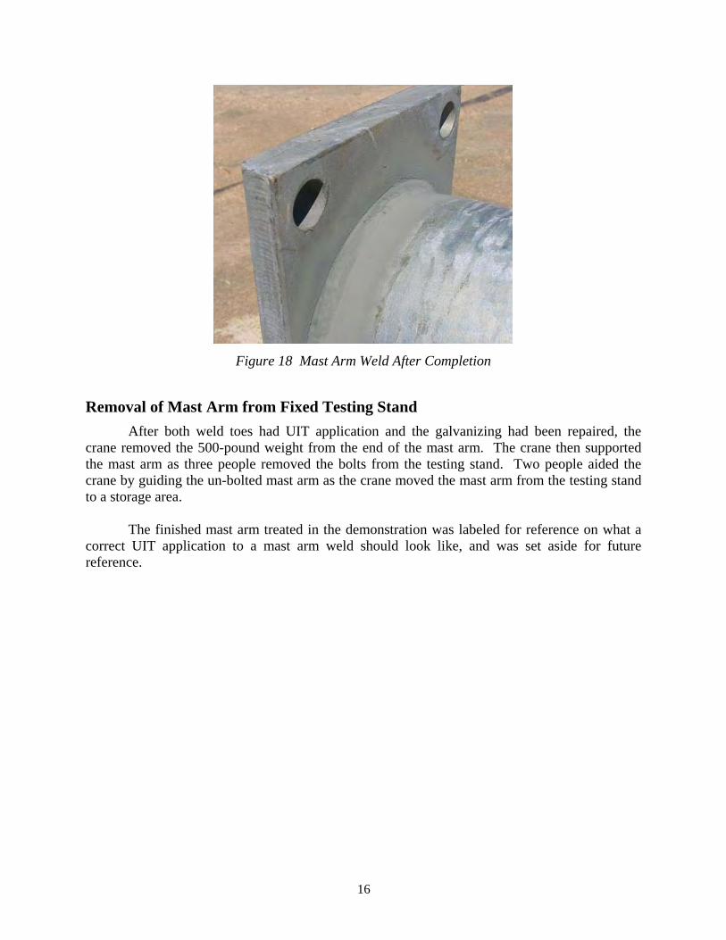
pure zinc. Figure 16 shows the paint being applied. Figure 17 shows the area of UIT application while the paint is drying. Figure 18 shows a completed UIT application after repair is completely dried.
Figure 16 Application of Zinc-Rich Paint
Figure 17 Drying Zinc-Rich Paint
16
Figure 18 Mast Arm Weld After Completion
Removal of Mast Arm from Fixed Testing Stand After both weld toes had UIT application and the galvanizing had been repaired, the
crane removed the 500-pound weight from the end of the mast arm. The crane then supported the mast arm as three people removed the bolts from the testing stand. Two people aided the crane by guiding the un-bolted mast arm as the crane moved the mast arm from the testing stand to a storage area.
The finished mast arm treated in the demonstration was labeled for reference on what a
correct UIT application to a mast arm weld should look like, and was set aside for future reference.

17
Applied Ultrasonics Technician Treatment Times Table 1 lists the times for each phase of UIT application to a mast arm weld during the
training demonstration
Table 1 Description of Phases of UIT Application
Phase Description
Applied Ultrasonics Technician
Times (minutes)
1 Move the mast arm with crane from stockpile to fixed testing stand, bolt the mast arm to the fixed testing stand, and apply the 500-pound
circular weight with the crane to the end of the fixed mast arm. 15
2 UIT application to the mast arm weld toe. 6 3 UIT application to the base plate weld toe. 5
4
Inspection of both mast arm and base plate weld toes, removal of galvanization flakes and remaining galvanization, touch-up of UIT application, and application of zinc-rich cold-spray galvanization
repair.
15
5 Unbolting the mast arm with UIT application and moving the mast arm by crane to a new stockpiled location. 4
Extra Discussion and breaks. 7 Total: 53

18

19
APPLICATION OF UIT BY TRAINED EMPLOYEES
The TransAmerican employees that were trained to apply UIT at the fabrication yard were present during the UIT application by the Applied Ultrasonics technician, but the employees were often not in the best position to view the UIT application technique. The employees that were being trained to apply UIT to the mast arm welds at the fabrication yard practiced first on a test plate weld. The test plate weld consisted of a small section of a base plate-mast arm connection. Figure 19 shows an employee practicing on the test plate.
Figure 19 Employee Applying UIT to a Test Plate Weld
After the employees became comfortable with the UIT process, they started UIT
application to a loaded mast arm weld in the setup. During the UIT application by the employee, the Applied Ultrasonics technician and Vice President of TransAmerican often had to stop the employee to show him by example the correct UIT application techniques. During the employee’s first UIT application of a mast arm weld he made many more passes than was necessary, did not always hold the tool at 45o, and was not able to keep the treatment along the weld toe. Figure 20 shows an employee applying UIT to the weld toe. The Uit tool is almost vertical, not at the desired 45o angle.

20
Figure 20 Employee’s First UIT Application to a Mast Arm Weld
TransAmerican Employee’s UIT Application Times The employee’s UIT application to a mast arm weld involved the same phases as the
Applied Ultrasonics technician, as listed in Table 1. The approximate times for the employee’s UIT application are listed in Table 2 Phases such as UIT application to the mast arm weld toe and the baseplate weld toe overlapped at times, so times are approximate.
Table 2 Employee’s First UIT Application to a Mast Arm Weld Times
Phase Description Applied
Ultrasonics Technician Times
(minutes)
TransAmerican Employee’s
Times (minutes)
1
Move the mast arm with crane from stockpile to fixed testing stand, bolt the mast arm to the fixed testing
stand, and apply the 500-pound circular weight with the crane to the end of the fixed mast arm.
15 7
2 UIT application to the mast arm weld toe. 6 35 3 UIT application to the base plate weld toe. 5 35
4
Inspection of both mast arm and base plate weld toes, removal of galvanization flakes and remaining galvanization, touch-up of UIT application, and application of zinc-rich cold-spray galvanization
repair.
15 20
5 Unbolting the mast arm with UIT application and moving the mast arm by crane to a new stockpiled
location. 4 5
Extra Discussion and breaks. 7 20 Total: 53 102

21
By the end of two days of training the employees, TransAmerican employees could complete three to four UIT applications and paint repairs to mast arms per day. However, after two weeks the employees were able to complete 10 to 15 UIT applications per day, according to a Houston TxDOT inspector.

22

23
DISCUSSION
Applied Ultrasonics Technician Treatment vs Trained TransAmerican Employee Treatment
Figure 20 shows that the TransAmerican employee held the UIT multi-pin tool at an extreme angle to the weld toe, not at the recommended 30o to 60o. The employee used more than the recommended two 1/8 inch diameter pins in the multi-pin UIT tool. The shiny areas visible in Figure 20 show that the employee’s UIT application strayed from the weld toe into the baseplate, mast arm, and weld metal by many millimeters. Excess UIT application is not in accordance with approved UIT application techniques, and the effects of excess UIT application are unknown. However, since compressive stresses and plastic deformation definitely take place, even in areas of excessive UIT application, it can be assumed that poor UIT application that results in excess UIT application area will still enhance the fatigue life of the mast arm weld. The UIT application by the Applied Ultrasonics technician, on the other hand, was in perfect accordance with the Applied Ultrasonics UIT application guidelines. The bolts attaching the mast arm to the testing setup hampered both the employee and Applied Ultrasonics technician during UIT application.
Treatment by the Applied Ultrasonics technician from start to finish took less than an
hour, and would have been less if the focus had been pure UIT application instead of instruction. Treatment by an employee on his first day of training can last for one to two hours, although the employee will have UIT application times comparable to a trained Applied Ultrasonics technician after a few weeks. The TransAmerican employee did not understand English, which slowed the learning process at TransAmerican. A possible way to increase employee productivity would be to teach the UIT application technique in the employee’s native language. Another possible way to expedite employee learning of UIT application is to have the employees being trained attend the morning presentation on UIT. By attending the morning UIT presentation, the employees being trained may feel more comfortable with the UIT tool when they begin their hands-on training.
UIT Application Concerns A concern with UIT raised by the TxDOT inspectors is under-treatment. A concern that
UIT needs to be applied entirely around the pole was raised, since cracks will find the new weakest spot in a connection. Since the mast arm-base plate connection is in compression on the bottom half of the mast arm, crack initiation in this area is not of concern.
Proper application of UIT requires that all galvanizing is removed during UIT
application. Occasionally, UIT application does not remove galvanizing correctly. The problem of flaking galvanizing interfering with UIT application may be prevented by removing galvanizing prior to UIT application.

24

25
REFERENCES
1. Koenigs, M.T.K. Fatigue Resistance of Traffic Signal Mast-Arm Connection Details. Masters of Science in Engineering Thesis, The University of Texas at Austin, May, 2003.
2. Mikheev PP, Nedoseka AY, Parkhomenko IV, Kuz’menko AZ, Statnikov ES, Senyukov VL, Chernetsov GP, Skvortsov VS. Effectiveness of Ultrasonic Treatment for Increasing the Fatigue Resistance of Welds. Russian Ultrasonics 1985; 15(4):70-75.
3. Haagensen PJ, Statnikov ES, Lopez-Martinez L. Introductory Fatigue Tests on Welded Joints in High Strength Steel and Aluminum Improved by Various Methods Including Ultrasonic Impact Treatment (UIT). IIW Doc. XIII-1748-98, 1998.
4. Lixing H, Dongpo W, Yufeng Z, Junmei C. Investigation on Improving Fatigue Properties of Welded Joints by Ultrasonic Peening Method. Welding in the World 2001; 45(3-4): 4-8.
5. Lihavainen VM, Marquis G, Statnikov ES. Fatigue Strength of a Longitudinal Attachment Improved by Ultrasonic Impact Treatment. Welding in the World 2004; 48(5-6): 67-73.
6. Statnikov ES, Muktepavel VO, Blomqvist A. Comparison of Ultrasonic Impact Treatment (UIT) and Other Fatigue Life Improvement Methods. Welding in the World 2002; 46(3-4): 20-32.
7. Tryfyakov VI, Mikheev PP, Kudryavtsev YF. Ultrasonic Impact Peening Treatment of Welds an Its Effect on Fatigue Resistance in Air and Seawater. Proceedings of the Annual Offshore Technology Conference, part 4, 1993: 183-187.
8. Takamori H, Fisher JW. Tests of Large Girders Treated to Enhance Fatigue Strength. Transportation Research Record 1696, Transportation Research Board, 2000.