traffic measurement for ip operations
TRANSCRIPT

Traffic Measurement for Traffic Measurement for IP OperationsIP Operations
Matthias Grossglauser and Jennifer RexfordMatthias Grossglauser and Jennifer Rexford
IP Network Management and PerformanceIP Network Management and PerformanceAT&T Labs AT&T Labs –– Research; Florham Park, NJResearch; Florham Park, NJ

Outline of Tutorial
• Introduction• Measurement techniques (part 1)
– Terminology and general techniques– Active measurement of performance– SNMP and RMON
• Measurement techniques (part 2)– Packet monitoring– Flow measurement– Data interpretation
• Measurement & models for traffic engineering– Path matrix (trajectory sampling, IP traceback)– Traffic matrix (network tomography, MPLS MIBs)– Demand matrix (joining flow and routing data)

Introduction: Outline
• Example challenge for network operators– Detect, diagnose, and fix
• Conflicting goals of IP and operators– Distributed vs. centralized control
• Overview of IP protocol suite (and challenges)– IP, TCP, DNS, and application-layer protocols
• Internet Service Provider networks– ISP architecture and routing protocols
• Responsibilities of network operators– Challenges, timescales, and key tasks

Network Operations: Detecting the Problem
overload!
Detecting the problem!• High utilization or loss statistics for the link?• High delay or low throughput for probe traffic?• Complaint from angry customer (via phone network)?
“Don’t IP networks manage themselves?”• Doesn’t TCP adapt automatically to network congestion?• Don’t the routing protocols automatically reroute after a failure?

Network Operations: Excess Traffic
Multi-homed customer
Two large flows of traffic
New egress pointfor first flow

Network Operations: DoS Attack
Denial-of-Service attack
Web server at its knees…
Install packetfilter
Web server back to life…

Network Operations: Link Failure
Link failure
New route overloads a link
Routing change alleviates congestion

Summary of the Examples
• How to detect that a link is congested?– Periodic polling of link statistics – Active probes measuring performance– Customer complaints
• How to diagnose the reason for the congestion?– Change in user behavior – Denial of service attack– Router/link failure or policy change
• How to fix the problem???– Interdomain routing change– Installation of packet filters– Intradomain routing change
Network measurement plays a key role in each step!

Tension Between Goals of IP Designers and Operators

IP Design Philosophy: Main Goals [Clark’88]
• Effective multiplexed utilization of existing networks– Packet switching, not circuit switching
• Continued communication despite network failures– Routers don’t store state about ongoing transfers– End hosts provide key communication services
• Support for multiple types of communication service– Multiple transport protocols (e.g., TCP and UDP)
• Accommodation of a variety of different networks– Simple, best-effort packet delivery service– Packets may be lost, corrupted, or delivered out of order
• Distributed management of network resources– Multiple institutions managing the network– Intradomain and interdomain routing protocols

Characteristics of the Internet
• The Internet is– Decentralized (loose confederation of peers)– Self-configuring (no global registry of topology)– Stateless (limited information in the routers)– Connectionless (no fixed connection between hosts)
• These attributes contribute– To the success of Internet– To the rapid growth of the Internet– … and the difficulty of controlling the Internet!
ISPsender receiver

Operator Philosophy: Tension With IP
• Accountability of network resources– But, routers don’t maintain state about transfers– But, measurement isn’t part of the infrastructure
• Reliability/predictability of services– But, IP doesn’t provide performance guarantees– But, equipment is not very reliable (no “five-9s”)
• Fine-grain control over the network– But, routers don’t do fine-grain resource allocation– But, network self-configures after failures
• End-to-end control over communication– But, end hosts adapt to congestion– But, traffic may traverse multiple domains

The Role of Traffic Measurement
• Operations (control)– Generating reports for customers and internal groups– Diagnosing performance and reliability problems– Tuning the configuration of the network to the traffic– Planning outlay of new equipment (routers, proxies, links)
• Science (discovery)– End-to-end characteristics of delay, throughput, and loss– Verification of models of TCP congestion control– Workload models capturing the behavior of Web users– Understanding self-similarity/multi-fractal traffic
• We focus helping operators run the network, and assume we have access to the network infrastructure

Measurement Challenges for Operators
• Network-wide view – Crucial for evaluating control actions – Multiple kinds of data from multiple locations
• Large scale– Large number of high-speed links and routers– Large volume of measurement data
• Poor state-of-the-art– Working within existing protocols and products– Technology not designed with measurement in mind
• The “do no harm” principle– Don’t degrade router performance – Don’t require disabling key router features– Don’t overload the network with measurement data

Overview of IP Protocol Suite

IP Protocols: Outline
• Internet Protocol (IP)– IP best-effort packet delivery service– IP addressing and packet forwarding
• Transmission Control Protocol (TCP)– Ordered reliable byte stream service at end hosts– Port numbers to identify the communicating applications– Congestion control to adapt to network load
• User Datagram Protocol (UDP)• Domain Name System (DNS)
– Translation between IP addresses and names
• Application-layer protocols (HTTP, FTP, SMTP,…)– Messages between end-host applications

Layering in the IP Protocols
Internet Protocol
Transmission ControlProtocol (TCP)
User Datagram Protocol (UDP)
TelnetHTTP
SONET ATMEthernet
RTPDNSFTP

IP Suite: End Hosts vs. Routers
HTTP
TCP
IP
Ethernetinterface
HTTP
TCP
IP
Ethernetinterface
IP IP
Ethernetinterface
Ethernetinterface
SONETinterface
SONETinterface
host host
router router
HTTP message
TCP segment
IP packet IP packetIP packet
Operator only has access to info inside the network

IP Connectionless Paradigm
• No error detection or correction for packet data– Higher-level protocol can provide error checking
• Successive packets may not follow the same path– Not a problem as long as packets reach the destination
• Packets can be delivered out-of-order– Receiver can put packets back in order (if necessary)
• Packets may be lost or arbitrarily delayed– Sender can send the packets again (if desired)
• No network congestion control (beyond “drop”)– Sender can slow down in response to loss or delay
Hard to tell the whole story from network measurements

IP Addressing
• 32-bit number in dotted-quad notation (12.34.158.5)
• Divided into network & host portions (left and right)
• 12.34.158.0/23 is a 23-bit prefix with 29 addresses
00001100 00100010 10011110 00000101
Network (23 bits) Host (9 bits)
12 34 158 5

Classless InterDomain Routing (CIDR)
• Prefixes are key to Internet scalability– Address allocation by ARIN/RIPE/APNIC and by ISPs– Routing protocols and packet forwarding based on prefixes– Today, routing tables contain ~100,000 prefixes
• Forwarding based on the longest prefix match– Destination-based forwarding of IP packets– Forwarding table maps prefix to next-hop link(s)– Router identifies the longest matching prefix
4.0.0.0/84.83.128.0/1712.0.0.0/812.34.158.0/23126.255.103.0/24
12.34.158.5

IP Addresses: Ambiguity
• Dynamic IP address assignment (DHCP)– Single client may have multiple addresses over time– Address may correspond to multiple clients over time
• Shared machines– Multiple users on a shared compute server– Transfers traveling through proxies and firewalls– Multiple Web sites hosted on a single machine
• Replicated sites– Multiple machines hosting a single (popular) Web site
• Addresses do not correspond to geographic location– Similar prefix does not necessarily imply nearby hosts– Single prefix may span hosts in large geographic region
• Source IP address may be spoofed (e.g., DoS attack)

Transmission Control Protocol (TCP)
• Communication service (socket)– Ordered, reliable byte stream for applications– Simultaneous transmission in both directions
• Key mechanisms at end hosts– Retransmission of lost or corrupted IP packets– Discard duplicate packets and reorder out-of-order packets– Flow control to avoid overloading the receiver buffer– Congestion control to adapt sending rate to network load
source network destination
TCP connection

Source and Destination Port Numbers
• Motivation for port numbers– Unique identifier of the TCP connection on each end– Necessary to (de)multiplex packets at the end-points
• Assigning port numbers– Port numbers below 1024 are assigned by IANA– Well-known port numbers for common applications
(http://www.iana.org/assignments/port-numbers)
• Web client contacting a web server– Browser click results in creation of a TCP socket– Client machine assigns an available port (>=1024)– Client machine requests a connection with the server– Open TCP connection to port 80 at the server

Port Numbers: Ambiguity
• Well-known port numbers (1023 and lower)– Use of non-traditional ports (e.g., 8000 and 8080 for Web)
– Reuse of well-known port numbers by other applications
• Unreserved port number (1024 and higher)– De facto ports for new applications (Napster, RealAudio)
– Peer-to-peer transfers; transfers between DDoS attackers
– Changing de facto ports to evade filtering (Napster)
• Dynamic port assignment– FTP data transfers (port #s conveyed in control stream)– RTSP multimedia transfers (port #s for RTP stream(s))

Opening and Closing a TCP Connection
• Three-way handshake to establish connection– Host A sends a SYN to the host B– Host B returns a SYN and acknowledgement– Host A sends an ACK to acknowledge the SYN ACK
• Four-way handshake to close the connection– Finish (FIN) to close and receive remaining bytes , or– Reset (RST) to close and not receive remaining bytes
SYN
SYN
AC
K
ACK
Dat
a
FIN
AC
K
AC
K
timeA
B
FIN
AC
K

Lost and Corrupted Packets
• Detecting corrupted and lost packets– Error detection via checksum on header and data
– Sender sends packet, sets timeout, and waits for ACK
– Receiver sends ACKs for received packets
– Sender infers loss from timeout or duplicate ACKs
• Retransmission by sender– Sender retransmits lost/corrupted packets
– Receiver reassembles and reorders packets
– Receiver discards corrupted and duplicated packets
Packet loss degrades application performance

TCP Flow and Congestion Control
• Window-based flow control– Sender limits number of outstanding bytes (window size)– Receiver window ensures data does not overflow receiver
• Adapting to network congestion– Congestion window tries to avoid overloading the network
(increase with successful delivery, decrease with loss)– TCP connection starts with small initial congestion window
timecon
ges
tio
n w
ind
ow
slow start
congestion avoidance

Many Factors Limiting TCP Performance
• Round-trip time (RTT)– Two-way delay between the sender and receiver
• Receiver window size– Buffer space available at the receiver
• Initial congestion window– Low throughput for short transfers
• Delay for detecting packet loss– Timeout value based on round-trip time
• Packet loss rate– Small congestion window under high loss
Hard to pinpoint the key factor limiting performance

User Datagram Protocol (UDP)
• Some applications do not want or need TCP– Avoid overhead of opening/closing a connection
– Avoid recovery from lost/corrupted packets
– Avoid sender adaptation to loss/congestion
• Example applications that use UDP– Multimedia streaming applications
– Domain Name System (DNS) queries/replies
– Delivery of measurement data (inband, unreliably!!!)
• Dealing with the growth in UDP traffic– Interference with TCP performance
– Pressure to apply congestion control
– Future routers may enforce “TCP-friendly” behavior

Domain Name System (DNS)
• Properties of DNS– Hierarchical name space divided into zones– Translation of names to/from IP addresses– Distributed over a collection of DNS servers
• Client application– Extract server name (e.g., from the URL)– Invoke system call to trigger DNS resolver code– E.g., gethostbyname() on “www.foo.com”
• Server application– Extract client IP address from socket– Optionally invoke system call to translate into name– E.g., gethostbyaddr() on “12.34.158.5”

Domain Name System
com edu org ac uk zw arpa
unnamed root
bar
west east
foo my
ac
cam
usr
in-addr
12
34
56
generic domains country domains
my.east.bar.edu usr.cam.ac.uk
12.34.56.0/24

DNS Resolver and Local DNS Server
Application
DNS resolver
Local DNSserver
1 10
DNS cache
DNS query
DNS response
2
9
Root server
Top-leveldomain server
Second-leveldomain server
3
4
5
6
7
8
Caching based on a time-to-live (TTL) assigned by the DNS server responsible for the host name to reduce latency in DNS translation.

Application-Layer Protocols
• Messages exchanged between applications– Syntax and semantics of the messages between hosts
– Tailored to the specific application (e.g., Web, e-mail)
– Messages transferred over transport connection (e.g., TCP)
• Popular application-layer protocols– Telnet, FTP, SMTP, NNTP, HTTP, …
Client ServerGET /index.html HTTP/1.1
HTTP/1.1 200 OK

Example: HTTP Delay
Browser cache
DNSresolution
TCPopen
1st byteresponse
Last byteresponse
Sources of variability of delay• Browser cache hit/miss, need for cache revalidation• DNS cache hit/miss, multiple DNS servers, errors• Packet loss, high RTT, server accept queue• RTT, busy server, CPU overhead (e.g., CGI script)• Response size, receive buffer size, congestion• … downloading embedded image(s) on the page

Hard to Tell Why Performance Stinks
• Multiple protocols– IP, TCP, DNS, and HTTP
• Multiple systems– Browser and Web servers, Web proxies and DNS servers
• Multiple domains– Numerous routers/links along request and response paths– Traffic traversing multiple autonomous systems en route
• No repeatability– Subsequent transfers may experience good performance– DNS caching, Web caching, different Web server replica,
different routes to/from server, transient congestion, …
How to “finger-point” to diagnose problems?

ISP Backgroundand
Network Operations
ISP Background: Outline
• Autonomous Systems (ASes)– Definition of an Autonomous System– Peer, provider, and customer relationships
• Internet Service Provider architecture– Example backbone network– Logical view of a backbone– Architecture of a high-end router– Different roles for routers
• Routing protocols– Border Gateway Protocol (BGP)– Interior Gateway Protocols (IGPs)
Internet Architecture
• Divided into Autonomous Systems– Distinct regions of administrative control (~11,500)
– Set of routers and links managed by a single “institution”
– Service provider, company, university, …
• Hierarchy of Autonomous Systems– Large, tier-1 provider with a nationwide backbone
– Medium-sized regional provider with smaller backbone
– Small network run by a single company or university
• Interaction between Autonomous Systems– Internal topology is not shared between ASes
– … but, neighboring ASes interact to coordinate routing

What is an “Institution”?
• Not equivalent to an AS– Many institutions span multiple autonomous systems– Some institutions do not have their own AS number– Ownership of an AS may be hard to pinpoint (whois)
• Not equivalent to a block of IP addresses (prefix)– Many institutions have multiple (non-contiguous) prefixes– Some institutions are a small part of a larger address block– Ownership of a prefix may be hard to pinpoint (whois)
• Not equivalent to a domain name (att.com)– Some sites may be hosted by other institutions– Some institutions have multiple domain names (att.net)
Attributing traffic/performance to an institution is hard

ISP 1
ISP 2
ISP 3
NAP
private peering
commercialcustomer
access router
gateway router
dial-in access
destination
destination
interdomainprotocols
intradomainprotocols
Connections Between ASes

Connecting to Neighboring ASes
• Public peering– Network Access Points (e.g., MAE East and MAE West)– Public location for connecting routers from different ISPs– Routers exchange both data and routing information
• Private peering– Private connections between two peers – Private peers exchange traffic between their customers– Private peers must exchange similar traffic volumes
• Transit networks– Customer pays its provider for transit service – Improve performance and reach more addresses– So-called “tier-1” providers do not receive transit services

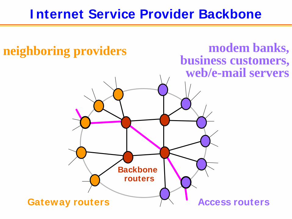
Internet Service Provider Backbone
modem banks,business customers,web/e-mail servers
neighboring providers
Gateway routers
Backbone routers
Access routers

Inside a High-End Router
SwitchingFabric
Processor
Line card
Line card
Line card
Line card
Line card
Line card

Components of a High-End Router
• Route processor– Implementation of the various routing protocols– Creation of forwarding table for the line cards– Command-line interface for network operators– Handling of packets directed to the Loopback address– Handling of “special packets” (IP options, expired TTL)
• Switching fabric– Forwarding of packet from input to output interface
• Line cards– Link-layer protocol to convert to/from IP packets– Packet handling (filtering, route look-up, buffering, rate
limiting, ToS marking, link scheduling,…)– Transfer of packet to/from the switching fabric

Three Roles for Routers
• Access Routers– Terminate a large number of customer links– Filter packets based on customer addresses– Enforce traffic limits and mark packets for QoS
• Backbone Routers– Connect between and within cities– High-speed switching in the core
• Gateway Routers– Connect to other providers and public access points– Implement routing policies for peering relationships

Interdomain Routing (Between ASes)
1
2
3
4
5
67
ClientWeb server
Path: 6, 5, 4, 3, 2, 1

Border Gateway Protocol (BGP)
• ASes exchange info about who they can reach
• Update messages exchanged over a TCP connection
• Local policies for path selection (which to use?)
• Local policies for route propagation (who to tell?)
• Policies configured by the AS’s network operator
1 2 3
12.34.158.5
“I can reach 12.34.158.0/23”
“I can reach 12.34.158.0/23 via AS 1”
flow of traffic

Interior Gateway Protocol (Within an AS)
• Routers flood information to learn the topology
• Routers determine “next hop” to reach other routers
• Path selection based on link weights (shortest path)
• Link weights configured by the network operator
32
2
1
13
1
4
5
3 Path cost = 8

Asymmetric Routes: Hot-Potato Routing
Web request and TCP ACKs
Web response
client
server

Network Operations: Outline
• Operating a network– Control loop, timescales, and practical challenges
• Operator tasks– Reporting, troubleshooting, traffic engineering,
provisioning, capacity planning, architecture
• Network model– Network state and data sources
• Conclusions

Operating a Network
• Control loop– Detect: note the symptoms– Diagnose: identify the illness– Fix: select and dispense the medicine
• Key ingredients– Measurement of the traffic and the network status– Analysis and modeling of the measurement data– Modeling of the network control mechanism (“what if”)
• Time scales– Minutes to hours– Days to weeks– Months to years
Practical Challenges
• Increase in the scale of the network– Link speeds, # of routers/links, # of peering points– Large network has 100s of routers and 1000s of links
• Significant traffic fluctuations– Time-of-day changes and addition of new customers/peers– Special events (Olympics) and new applications (Napster)– Difficult to forecast traffic load before designing topology
• Market demand for stringent network performance– Service level agreements (SLAs), high-quality voice-over-IP
• Increase in network capability & feature complexity– New services (Quality of Service, Virtual Private Networks) – New routing protocols (MPLS, multicast)

Network Operations Tasks
• Reporting of network-wide statistics– Generating basic information about usage and reliability
• Performance/reliability troubleshooting – Detecting and diagnosing anomalous events
• Traffic engineering– Adjusting network configuration to the prevailing traffic
• Capacity planning– Deciding where and when to install new equipment
• Provisioning of existing network– Process of adding new customers/peers, routers/links, etc.
• Selecting and testing new network architectures– MPLS routing, multicast, monitoring, quality-of-service, ...

Basic Reporting
• Producing basic statistics about the network– For business purposes, network planning, ad hoc studies
• Examples– Proportion of transit vs. customer-customer traffic– Total volume of traffic sent to/from each private peer– Mixture of traffic by application (Web, Napster, etc.)– Mixture of traffic to/from individual customers– Usage, loss, and reliability trends for each link
• Requirements– Network-wide view of basic traffic and reliability statistics– Ability to “slice and dice” measurements in different ways
(e.g., by application, by customer, by peer, by link type)

Topology and Link Utilization
Utilization: link color (high to low)

Troubleshooting
• Detecting and diagnosing problems– Recognizing and explaining anomalous events
• Examples– Why a backbone link is suddenly overloaded– Why the route to a destination prefix is flapping– Why DNS queries are failing with high probability– Why a route processor has high CPU utilization– Why a customer cannot reach certain Web sites
• Requirements– Network-wide view of many protocols and systems– Diverse measurements at different protocol levels– Thresholds for isolating significant phenomena

Traffic Flow Through Backbone
Color/size of node: proportional to traffic to this router (high to low)Color/size of link: proportional to traffic carried (high to low)
Peering point

Traffic Engineering
• Adjusting resource allocation policies– Path selection, buffer management, and link scheduling
• Examples– Changing IGP weights to divert traffic from congested links– Changing BGP policies to balance load on peering links– Changing RED parameters to improve TCP throughput– Changing WFQ weights to reduce delay for “gold” traffic
• Requirements– Network-wide view of the traffic carried in the backbone– Timely view of the network topology and configuration– Accurate models to predict impact of control operations
(e.g., the impact of RED parameters on TCP throughput)

BGP Policy Change
Multi-homed customer
Two large flows of traffic
New egress pointfor the flow

Capacity Planning
• Deciding whether to buy/install new equipment– What? Where? When?
• Examples– Where to put the next backbone router– When to upgrade a peering link to higher capacity– Whether to add/remove a particular private peer– Whether the network can accommodate a new customer– Whether to install a caching proxy for cable modems
• Requirements– Projections of future traffic patterns from measurements– Cost estimates for buying/deploying the new equipment– Model of the potential impact of the change (e.g., latency
reduction and bandwidth savings from a caching proxy)

Network State: Not Just Traffic Measurement
• Topology– Routers and links, and their connectivity and capacity
– BGP sessions with neighbors and within the backbone
• Configuration– Path selection (e.g., OSPF weights, BGP policies)
– Link scheduling (e.g., FIFO or WFQ weights)
– Buffer management (e.g., drop-tail or RED parameters)
– Packet filters (e.g., ingress filters to prevent DoS)
• Interdomain routing– Reachability to neighboring domains (e.g., BGP updates)
Necessary for a network-wide view for the operator
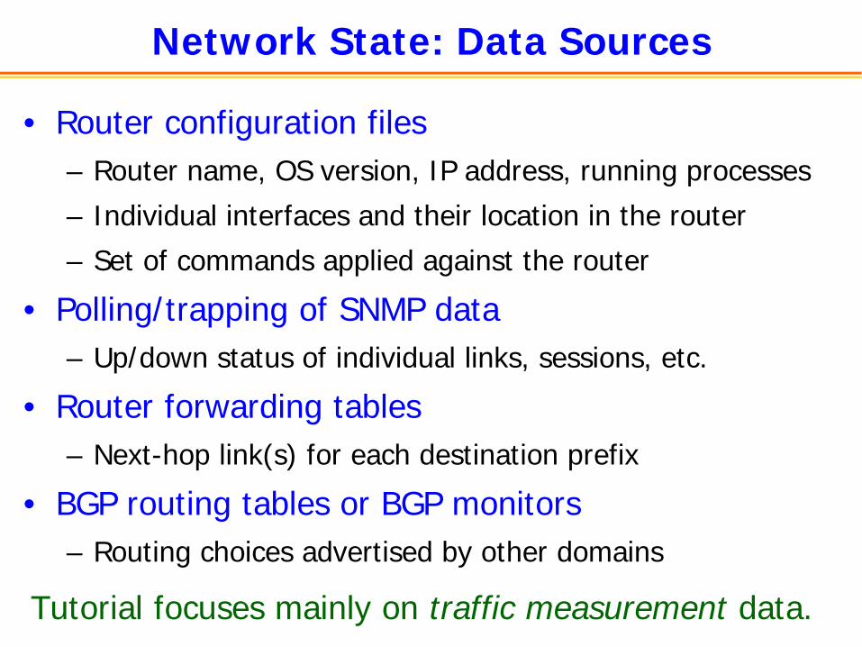
Network State: Data Sources
• Router configuration files– Router name, OS version, IP address, running processes
– Individual interfaces and their location in the router
– Set of commands applied against the router
• Polling/trapping of SNMP data– Up/down status of individual links, sessions, etc.
• Router forwarding tables– Next-hop link(s) for each destination prefix
• BGP routing tables or BGP monitors– Routing choices advertised by other domains
Tutorial focuses mainly on traffic measurement data.

Example: Router Configuration File
• Language with hundreds of different commands• Cisco IOS is a de facto standard config language• Sections for interfaces, routing protocols, filters, etc.
version 12.0hostname MyRouter!interface Loopback0ip address 12.123.37.250 255.255.255.255
!interface Serial9/1/0/4:0description MyT1Customerbandwidth 1536ip address 12.125.133.89 255.255.255.252ip access-group 10 in
!
interface POS6/0description MyBackboneLinkip address 12.123.36.73 255.255.255.252ip ospf cost 1024
!router ospf 2network 12.123.36.72 0.0.0.3 area 9network 12.123.37.250 0.0.0.0 area 9
!access-list 10 permit 12.125.133.88 0.0.0.3access-list 10 permit 135.205.0.0 0.0.255.255ip route 135.205.0.0 255.255.0.0 Serial9/1/0/4:0

Example: Forwarding Table (“show ip cef”)
Prefix Next Hop Interface4.20.90.120/29 12.123.28.134 POS7/0
12.123.28.130 POS6/04.20.90.128/29 12.123.28.130 POS6/04.24.7.104/30 12.123.28.134 POS7/04.36.100.0/23 192.205.32.126 ATM5/0.16.0.0.0/8 12.123.28.134 POS7/0
12.123.28.130 POS6/09.2.0.0/16 192.205.32.126 ATM5/0.19.3.4.0/24 12.123.28.130 POS6/09.3.5.0/24 12.123.28.130 POS6/09.20.0.0/17 192.205.32.178 POS0/3
Random or hash-based tie-break to select among multiple next-hops

Example: BGP Table (“show ip bgp” at RouteViews)
Network Next Hop Metric LocPrf Weight Path* 3.0.0.0 205.215.45.50 0 4006 701 80 i* 167.142.3.6 0 5056 701 80 i* 157.22.9.7 0 715 1 701 80 i* 195.219.96.239 0 8297 6453 701 80 i* 195.211.29.254 0 5409 6667 6427 3356 701 80 i*> 12.127.0.249 0 7018 701 80 i* 213.200.87.254 929 0 3257 701 80 i* 9.184.112.0/20 205.215.45.50 0 4006 6461 3786 i* 195.66.225.254 0 5459 6461 3786 i*> 203.62.248.4 0 1221 3786 i* 167.142.3.6 0 5056 6461 6461 3786 i* 195.219.96.239 0 8297 6461 3786 i* 195.211.29.254 0 5409 6461 3786 i
AS 80 is General Electric, AS 701 is UUNET, AS 7018 is AT&TAS 3786 is DACOM (Korea), AS 1221 is Telstra

Conclusions
• Operating IP networks is hard– Basic design philosophy of the IP protocols– Division of Internet into multiple (competing) ASes
• Measurement and models play a crucial role– Constructing a real-time, network-wide view– Detecting, diagnosing, and fixing problems
• Next two 1.5-hour parts of the tutorial– Overview of the key measurement techniques
• Final 1.5-hour part of the tutorial– Measurement and models for traffic engineering