traffic channel allocation - nchu.edu.twwccclab.cs.nchu.edu.tw/www/images/wireless_network/chapter...
TRANSCRIPT

Copyright © 2011, Dr. Dharma P. Agrawal and Dr. Qing-An Zeng. All rights reserved. 1
Chapter 8
Traffic Channel Allocation

Copyright © 2011, Dr. Dharma P. Agrawal and Dr. Qing-An Zeng. All rights reserved. 2
Outline
Introduction Static Allocation versus Dynamic allocation Fixed Channel Allocation (FCA) Dynamic Channel Allocation (DCA) Hybrid Channel Allocation (HCA) Allocation in Specialized System Structure System Modeling

Copyright © 2011, Dr. Dharma P. Agrawal and Dr. Qing-An Zeng. All rights reserved. 3
Introduction What is channel allocation? A given radio spectrum is to be divided into a
set of disjointed channels that can be used simultaneously while minimizing interference in adjacent channel by allocating channels appropriately (especially for traffic channels)
Stotal channels equally partitioned among N cells with each cell with S channels as
S=Stotal/N, e.g., 140/7=20 Channel allocation schemes can be divided in
general into Static versus Dynamic Fixed Channel Allocation (FCA); Dynamic Channel Allocation (DCA); Hybrid Channel Allocation (HCA).

Copyright © 2011, Dr. Dharma P. Agrawal and Dr. Qing-An Zeng. All rights reserved. 4
Fixed Channel Allocation (FCA) In FCA, a set of channels is
permanently allocated to each cell Number of available channels S is
divided into sets, the minimum number of channel sets N required is related to the frequency reuse distance D as follows:
N = D2 / 3R2 or If a cell of cluster A1 borrows channel,
there should not be interference with cells A2, A3, A4, A5, A6, and A7
A1,1 : Channels 1-20, A1,2 : Channels 21-40 A1,3 : Channels 41-60, A1,4: Channels 61-80 A1,5 : Channels 81-100, A1,6 : Channels 101-120 A1,7 : Channels 120-140
RDN3
=
A7 A2
A1
A3
A4
A5
A6
A1,6
A1,5
A1,4 A1,3
A1,7
A1,2
,1

Copyright © 2011, Dr. Dharma P. Agrawal and Dr. Qing-An Zeng. All rights reserved. 5
Simple Borrowing Schemes Cell (acceptor cell) that has used all its nominal
channels can borrow free channels from its neighboring cell (donor cell) to accommodate new calls.
Borrowing can be done from an adjacent cell which has largest number of free channels (borrowing from the richest)
Select the first free channel found for borrowing using a search algorithm (borrow first available scheme)
Return the borrowed channel when channel becomes free in the cell (basic algorithm with reassignment)
To be available for borrowing, the channel must not interfere with existing calls, as shown in the next figure

Copyright © 2011, Dr. Dharma P. Agrawal and Dr. Qing-An Zeng. All rights reserved. 6
Simple Channel Borrowing Schemes
X Z
Y 2
1 Cell 3
Donor Cell for Sector X
A call initiated in the sector X of cell 3 can borrow a channel from adjacent cells 1 or 2

Copyright © 2011, Dr. Dharma P. Agrawal and Dr. Qing-An Zeng. All rights reserved. 7
Simple Channel Borrowing Schemes Scheme Description
Simple Borrowing (SB)
A nominal channel set is assigned to a cell, as in the FCA case. After all nominal channels are used, an available channel from a neighboring cell is borrowed
Borrow from the Richest (SBR)
Channels that are candidates for borrowing are available channels nominally assigned to one of the adjacent cells of the acceptor cell. If more than one adjacent cell has channels available for borrowing, a channel is borrowed from the cell with the greatest number of channels available for borrowing
Basic Algorithm (BA)
This is an improved version of the SBR strategy which takes channel locking into account when selecting a candidate channel for borrowing. This scheme tried to minimize the future call blocking probability in the cell that is most affected by the channel borrowing
Basic Algorithm with Reassignment
This scheme provides for the transfer of a call from a borrowed channel to a nominal channel whenever a nominal channel becomes available
Borrow First Available
Instead of trying to optimize when borrowing, this algorithm selects the first candidate channel it finds

Copyright © 2011, Dr. Dharma P. Agrawal and Dr. Qing-An Zeng. All rights reserved. 8
Complex Channel Borrowing using Sectored Cell-based Wireless System
A7
A2
A1
A3
A4
A5
A6
c c
c
c
c c
c
a a
a
a
a a
b b
b
b
b b
b x a
X borrows some channels from a

Copyright © 2011, Dr. Dharma P. Agrawal and Dr. Qing-An Zeng. All rights reserved.
CBS When some channels are borrowed from
sector “a” of A1 to sector “x” of A3, there could be potential violation of reuse distance.
Looking at the distance between “x” and sector “a” of other cluster, only cluster A5, A6, and A7 satisfy the reuse distance.
9

Copyright © 2011, Dr. Dharma P. Agrawal and Dr. Qing-An Zeng. All rights reserved. 10
Dynamic Channel Allocation (DCA)
In DCA schemes, all channels are kept in a central pool and are assigned dynamically to new calls as they arrive in the system
After each call is completed, the channel is returned to the central pool. Select the most appropriate channel for any call based simply on current allocation and current traffic, with the aim of minimizing the interference
DCA scheme can overcome the problem of FCA scheme. However, variations in DCA schemes center around the different cost functions used for selecting one of the candidate channels for assignment
Copyright © 2011, Dr. Dharma P. Agrawal and Dr. Qing-An Zeng. All rights reserved. 11
Dynamic Channel Allocation (DCA) DCA schemes can be centralized or distributed The centralized DCA scheme involves a single
controller selecting a channel for each cell The distributed DCA scheme involves a number of
controllers scattered across the network (MSCs) Centralized DCA schemes can theoretically provide
the best performance. However, the enormous amount of computation and communication among BSs leads to excessive system latencies and renders centralized DCA schemes impractical. Nevertheless, centralized DCA schemes often provide a useful benchmark to compare practical decentralized DCA schemes

Copyright © 2011, Dr. Dharma P. Agrawal and Dr. Qing-An Zeng. All rights reserved. 12
Centralized DCA
For a given reuse distance, cell can be identified that satisfy minimum reuse distance; all these cells could be allocated the same channel and are defined as co-channel cells.
For a new call, a free channel from the central pool is selected that would maximize the number of members in its co-channel set
Minimize the mean square of distance between cells using the same channel

Copyright © 2011, Dr. Dharma P. Agrawal and Dr. Qing-An Zeng. All rights reserved. 13
Centralized DCA Schemes Scheme Description
First Available (FA) Among the DCA schemes the simplest one is the FA strategy. In F A, the first available channel within the reuse distance encountered during a channel search is assigned to the call. The FA strategy minimizes the system computational time
Locally Optimized Dynamic Assignment (LODA)
The channel selection is based on the future blocking probability in the vicinity of the cell where a call is initiated
Selection with Maximum Usage on the Reuse Ring (RING)
A candidate channel is selected which is in use in the most cells in the co-channel set. If more than one channel has this maximum usage, an arbitrary selection among such channel is made to serve the call. If none is available, then the selection is made based on the FA scheme

Copyright © 2011, Dr. Dharma P. Agrawal and Dr. Qing-An Zeng. All rights reserved. 14
Centralized DCA Schemes
Scheme Description Mean Square (MSQ)
The MSQ scheme selects the available channel that minimizes the mean square of the distance among the cells using the same channel
1-clique This scheme uses a set of graphs, one for each channel, expressing the non co-channel interference structure over the whole service area for that channel

Copyright © 2011, Dr. Dharma P. Agrawal and Dr. Qing-An Zeng. All rights reserved. 15
Distributed DCA Schemes
Based on one of the three parameters: Co-channel distance - co-channel cells in the neighborhood not using the
channel - sometimes adjacent channel interference taken in
to account Signal strength measurement - anticipated co-channel interference ratio (CCIR)
above threshold Signal to noise interference ratio - satisfy desired CIR ratio

Copyright © 2011, Dr. Dharma P. Agrawal and Dr. Qing-An Zeng. All rights reserved. 16
Comparison between FCA and DCA FCA DCA
Performs better under heavy traffic Low flexibility in channel assignment Maximum channel reusability Sensitive to time and spatial changes Unstable grade of service per cell in an interference cell group High forced call termination probability Suitable for large cell environment Low flexibility
Performs better under light/moderate traffic Flexible channel allocation Not always maximum channel reusability Insensitive to time and time spatial changes Stable grade of service per cell in an interference cell group Low to moderate forced call termination probability Suitable in microcellular environment High flexibility

Copyright © 2011, Dr. Dharma P. Agrawal and Dr. Qing-An Zeng. All rights reserved. 17
Comparison between FCA and DCA FCA DCA
Radio equipment covers all channels assigned to the cell Independent channel control Low computational effort Low call set up delay Low implementation complexity Complex, labor intensive frequency planning Low signaling load Centralized control
Radio equipment covers the temporary channel assigned to the cell Fully centralized to fully distributed control dependent on the scheme High computational effort Moderate to high call set up delay Moderate to high implementation complexity No frequency planning Moderate to high signaling load Centralized, distributed control depending on the scheme

Copyright © 2011, Dr. Dharma P. Agrawal and Dr. Qing-An Zeng. All rights reserved.
表8.1 固定與動態通道分配方案之比較
18 第 8 章 通道分配 第 212 頁

Copyright © 2011, Dr. Dharma P. Agrawal and Dr. Qing-An Zeng. All rights reserved. 19
Other Channel Allocation Schemes
Based on different criterion being used as a potential way of optimizing the performance, many other channel allocation schemes have been suggested Hybrid Channel Allocation (HCA) Flexible Channel Allocation (FCA) Handoff Channel Allocation (HCA)

Copyright © 2011, Dr. Dharma P. Agrawal and Dr. Qing-An Zeng. All rights reserved. 20
Hybrid Channel Allocation (HCA) HCA schemes are the combination of both FCA and DCA
techniques In HCA schemes, the total number of channels available
for service is divided into fixed and dynamic sets The fixed set contains a number of nominal channels
that are assigned to cells as in the FCA schemes and, in all cases, are to be preferred for use in their respective cells
The dynamic set is shared by all users in the system to increase flexibility
Example: When a call requires service from a cell and all of its nominal channels are busy, a channel from the dynamic set is assigned to the call

Copyright © 2011, Dr. Dharma P. Agrawal and Dr. Qing-An Zeng. All rights reserved. 21
Hybrid Channel Allocation (HCA)
Request for a channel from the dynamic set is initiated only when the cell has exhausted using all its channels from the fixed set
Optimal ratio: ratio of number of fixed and dynamic channels 3:1 (fixed to dynamic) (105 versus 35 channels), provides better service than fixed scheme for traffic up to 50%.
For dynamic, with traffic load of 15% to 32%, better results are found with HCA
Copyright © 2011, Dr. Dharma P. Agrawal and Dr. Qing-An Zeng. All rights reserved. 22
Flexible Channel Allocation (FCA)
Similar to hybrid scheme with channels divided into fixed and flexible (emergency) sets
Fixed sets used to handle lighter loads Variations in traffic (peaks in time and space) are
needed to schedule emergency channels Two types: Scheduled and Predictive Scheduled: Prior estimate is done about traffic
change Predictive: Traffic intensity and blocking
probability is monitored in each cell all the time

Copyright © 2011, Dr. Dharma P. Agrawal and Dr. Qing-An Zeng. All rights reserved. 23
Channel Allocation in One-dimensional Systems
1 2 3 4 5 6 7 8 Call initiated
Reuse distance D
a b c d
e
If a new call is initiated in cell 1, with the current location of channels a, b, c, d, e as shown. It is better to assign channel e to mobile in cell 1. Assuming that as cell 1 moves to cell 2, MS in cell 7 moves to cell 8

Copyright © 2011, Dr. Dharma P. Agrawal and Dr. Qing-An Zeng. All rights reserved. 24
Reuse Partitioning based Channel Allocation
Each cell is divided into concentric zones. Inner zone being closer to BS would require
lesser power to attain a desired channel
1 2 3 4

Copyright © 2011, Dr. Dharma P. Agrawal and Dr. Qing-An Zeng. All rights reserved. 25
Overlapped Cells-based Allocation
Cell splitting into number of smaller cells (pico, micro cells), to handle increased traffic
For fast moving MS, if channels are assigned from micro cell, no. of handoffs will increase
Therefore highly mobile cells are assigned channels from the cell
MS with low mobility are assigned to micro- or pico-cells

Copyright © 2011, Dr. Dharma P. Agrawal and Dr. Qing-An Zeng. All rights reserved.
Microcell
7
2
3
6
5
4
1
26
Overlapped Cells-based Allocation
Cell

Copyright © 2011, Dr. Dharma P. Agrawal and Dr. Qing-An Zeng. All rights reserved. 27
Use of Overlapped Cell Areas
In the shared area Handoffs not necessary Worst Case Scenario: if MS in shared area does not
find a free channel in cell A, it can take the free channel from cell B
C A B

Copyright © 2011, Dr. Dharma P. Agrawal and Dr. Qing-An Zeng. All rights reserved.
Universal Cell Phone Coverage
Originating Call Handoff Call
Microwave Tower
Cell
Cincinnati
Washington, DC

Copyright © 2011, Dr. Dharma P. Agrawal and Dr. Qing-An Zeng. All rights reserved. 29
System Modeling
The follows assumptions are made to obtain an approximate model of system All MSs are assumed to be uniformly
distributed through the cell Each MS moves at a random speed and to an
arbitrary random direction The arrival rate of originating call is given
by λO The arrival rate of handoff call is given by λH The call service rate is given by µ

Copyright © 2011, Dr. Dharma P. Agrawal and Dr. Qing-An Zeng. All rights reserved. 30
System Model
S
.
.
2
1 Channels
µ
λH
λO
A generic system model for a cell with S channels
λO originating call rate
λH handoff call rate
µ service rate

Copyright © 2011, Dr. Dharma P. Agrawal and Dr. Qing-An Zeng. All rights reserved. 31
Analysis Model (cont’d)
The follows parameters are defined in the analysis model P(i): the probability of “i” channels to be busy λO : the arrival rate of an originating call in the cell λH : the arrival rate of a handoff call from neighboring
cells BO : the blocking probability of originating calls S : the total number of channels allocated to a cell µ: the call service rate µc : the average call duration µc-dwell: the outgoing rate of MSs

Copyright © 2011, Dr. Dharma P. Agrawal and Dr. Qing-An Zeng. All rights reserved. 32
Basic Modeling
The states of a cell can be represented by (S+1) states Markov model. And a transition diagram of M/M/S/S model as shown below.
µ (i+1)µ iµ Sµ
State transition diagram
S0 ),1()()( O ≤≤−+= iiPiPi Hλλµ
· · · · · · 0
λO+ λH
i
λO+ λH λO+ λH
S
λO+ λH
i-1

Copyright © 2011, Dr. Dharma P. Agrawal and Dr. Qing-An Zeng. All rights reserved. 33
Basic Modeling (cont’d) The state equilibrium equation for state i can be given as And the sum of all states must to be equal to one:
The steady-state probability P(i) is easily found as follows:
S0 ),1()( O ≤≤−+
= iiPi
iP H
µλλ
∑=
=S
01)(
iiP
whereS0),0(!
)()( 0 ≤≤+
= iPi
iP i
iH
µλλ
1
0
!)()0(
−
+= ∑ i
iH
iP
µλλ
Copyright © 2011, Dr. Dharma P. Agrawal and Dr. Qing-An Zeng. All rights reserved. 34
Basic Modeling (cont’d)
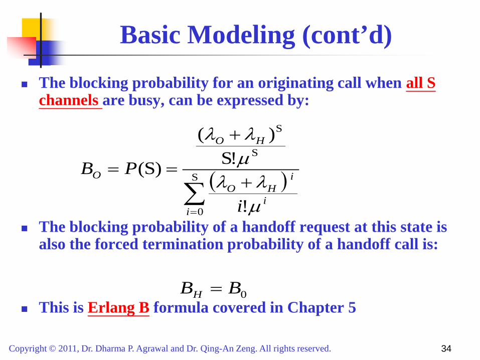
The blocking probability for an originating call when all S channels are busy, can be expressed by:
The blocking probability of a handoff request at this state is also the forced termination probability of a handoff call is:
This is Erlang B formula covered in Chapter 5
0BBH =
( )∑=
+
+
== S
0
S
S
!
!S)(
)S(
ii
iHO
HO
O
i
PB
µλλ
µλλ

Copyright © 2011, Dr. Dharma P. Agrawal and Dr. Qing-An Zeng. All rights reserved. 35
Modeling for Channel Reservation
Why should we provide a higher priority to handoff calls?
From users’ view, the dropping of handoff calls is more serious and irritating than the blocking of originating calls
How to provide a higher priority to handoff calls?
One approach is reserve SR channels exclusively for handoff calls among the S channels in a cell

Copyright © 2011, Dr. Dharma P. Agrawal and Dr. Qing-An Zeng. All rights reserved. 36
System Model with reserved channels
S
.
SC
.
.
2
1 Channels
λH
λO
µ
SR
System model with reserved channels for handoff (No blocking of originating calls till less than SC channels are busy)
Reserved only for handoff calls

Copyright © 2011, Dr. Dharma P. Agrawal and Dr. Qing-An Zeng. All rights reserved. 37
Analytical Model
λO+ λH λH λO+ λH
0 · · · µ
SC · · · (SC+1)µ SCµ
S λH
Sµ
State transition diagram
The state balance equations can be obtained as
and
≤<−=≤≤−+=
SS ),1()(S0 ),1()()(
C
C
iiPiPiiiPiPi
H
HO
λµλλµ
∑=
=S
0.1)(
iiP

Copyright © 2011, Dr. Dharma P. Agrawal and Dr. Qing-An Zeng. All rights reserved. 38
Analytical Modeling (cont’d) The steady-state probability P(i) can be obtained as: Where
≤<+
≤≤+
= −
SS ),0(!
)(
S0 ),0(!
)(
)(
c
SSO
cO
cc
iPi
iPi
iP
i
i
HH
i
iH
µλλµλλ
λ
1S
1S
SS0
S
0
0
c
ccc
!)(
!)()0(
−
+=
−
=
++
+= ∑∑
ii
iHH
ii
iH
iiP
µλλλ
µλλ

Copyright © 2011, Dr. Dharma P. Agrawal and Dr. Qing-An Zeng. All rights reserved. 39
Analytical Model (Cont’d)
The blocking probability BO for an originating call is given by (at least SC channels busy):
The blocking probability BH for a handoff call is
(all S channels busy) or forced termination probability of handoff call is:
∑=
=S
SC
)(i
o iPB
( ) )0(!S
)S( S
SSSC
PPBC
HHOH µ
λλλ −+==