trademarks - amazon simple storage service · building the perfect ski boat is only surpassed by...
TRANSCRIPT
i
All information and specifications included in this manual were in effect at the time ofapproval for printing. Malibu Boats LLC reserves the right, however, to discontinue orchange specifications or design at any time without notice and without incurring anyobligation.
Trademarks
Malibu, The Malibu Logo is a registered trademark of Malibu Boats LLC.
Indmar, Indmar is a registered trademark of Indmar Products Co., Inc.
All other product names are copyright and registered trademarks/trade names of theirrespective owners.
© 2000, 2001, 2002, 2003, 2004, 2005, 2006, 2007, 2008, 2009, 2010 Malibu Boats LLC. All Rights reserved.Printed in the USA
Chapter i_10:Chapter i.qxd 11/3/09 10:01 AM Page i

ii
Chapter i_10:Chapter i.qxd 11/3/09 10:01 AM Page ii

CONTENTS . . . . . . . . . . . . . . . . . . . . . iii
TABLE OF FIGURES. . . . . . . . . . . . . iv
INTRODUCTION. . . . . . . . . . . . . . . . . v
CERTIFICATIONS & STANDARDS . . v
MODEL FEATURES &SPECIFICATIONS. . . . . . . . . . . . . . . vii
BOATING SAFETY . . . . . . . . . . . . . 1-1
General Precautions . . . . . . . . . . . . 1-1Safety Statements . . . . . . . . . . . . . . 1-1Regulations. . . . . . . . . . . . . . . . . . . 1-3Responsibilities . . . . . . . . . . . . . . . 1-3Emergencies . . . . . . . . . . . . . . . . . . 1-6Hazardous Conditions . . . . . . . . . . 1-7Carbon Monoxide. . . . . . . . . . . . . . 1-9Operation by Minors . . . . . . . . . . 1-10Passenger Safety. . . . . . . . . . . . . . 1-10Basic Rules of the Road . . . . . . . . 1-10
GAUGES & CONTROLS. . . . . . . . . 2-1
Standard Gauges. . . . . . . . . . . . . . . 2-1Power Wedge . . . . . . . . . . . . . . . . 2-22Circuit Breakers . . . . . . . . . . . . . . 2-27Switches & Indicators . . . . . . . . . 2-27Throttle Control . . . . . . . . . . . . . . 2-36Steering System . . . . . . . . . . . . . . 2-37Emergency Engine Stop Switch. . 2-37Motorbox Cover . . . . . . . . . . . . . . 2-37Driver’s Seat. . . . . . . . . . . . . . . . . 2-38Integral Self Draining
Ice Chest . . . . . . . . . . . . . . . . . 2-39Sundeck . . . . . . . . . . . . . . . . . . . . 2-39V-Drive Engine Access
Hatch. . . . . . . . . . . . . . . . . . . . 2-39Ski Pylon . . . . . . . . . . . . . . . . . . . 2-39Swim Platform . . . . . . . . . . . . . . . 2-40
Navigational Lights . . . . . . . . . . . 2-41Storage Areas . . . . . . . . . . . . . . . . 2-41Drain Plugs. . . . . . . . . . . . . . . . . . 2-42Speedometer Pickup. . . . . . . . . . . 2-43Tilt Steering Wheel . . . . . . . . . . . 2-43Exhaust . . . . . . . . . . . . . . . . . . . . . 2-44Ventilation . . . . . . . . . . . . . . . . . . 2-45Optional Equipment . . . . . . . . . . . 2-46Wedge. . . . . . . . . . . . . . . . . . . . . . 2-57
OPERATION . . . . . . . . . . . . . . . . . . . 3-1
Trailering . . . . . . . . . . . . . . . . . . . . 3-1Warning Labels . . . . . . . . . . . . . . . 3-4Fueling . . . . . . . . . . . . . . . . . . . . . . 3-7Starting . . . . . . . . . . . . . . . . . . . . . . 3-8Shifting/Running . . . . . . . . . . . . . 3-10Steering . . . . . . . . . . . . . . . . . . . . 3-10Stopping . . . . . . . . . . . . . . . . . . . . 3-12Docking . . . . . . . . . . . . . . . . . . . . 3-13High-Speed Operation . . . . . . . . . 3-14Towing a Skier . . . . . . . . . . . . . . . 3-14Towing Another Boat . . . . . . . . . . 3-16Anchoring. . . . . . . . . . . . . . . . . . . 3-16Propellers . . . . . . . . . . . . . . . . . . . 3-17Malibu Exclusive Adjustable
Rudder System . . . . . . . . . . . . 3-18Corrosion Protection . . . . . . . . . . 3-19
CARE AND MAINTENANCE. . . . . 4-1
Interior . . . . . . . . . . . . . . . . . . . . . . 4-1Exterior. . . . . . . . . . . . . . . . . . . . . . 4-3Engine/Drive Train. . . . . . . . . . . . . 4-5Fuel System . . . . . . . . . . . . . . . . . . 4-9Electrical . . . . . . . . . . . . . . . . . . . 4-10Miscellaneous. . . . . . . . . . . . . . . . 4-14Troubleshooting . . . . . . . . . . . . . . 4-17Glossary . . . . . . . . . . . . . . . . . . . . 4-20Index. . . . . . . . . . . . . . . . . . . . . . . 4-21
iii
CONTENTS
Chapter i_10:Chapter i.qxd 11/4/09 1:11 PM Page iii

iv
TABLE OF FIGURESFigure 1-1 Personal Flotation
Devices . . . . . . . . . . . . . . . . . . . . . . . . 1-5Figure 1-2 Fire Extinguisher . . . . . . . . . . . . 1-6Figure 1-3 Weather Hazards . . . . . . . . . . . . 1-7Figure 1-4 Diver Down Flag. . . . . . . . . . . . 1-8Figure 1-5 Carbon Monoxide
Hazards . . . . . . . . . . . . . . . . . . . . . . . . 1-9Figure 1-6 Types of Buoys . . . . . . . . . . . . 1-11Figure 1-7 Mooring Buoys . . . . . . . . . . . . 1-11Figure 1-8 Regulatory Markers. . . . . . . . . 1-11Figure 1-9 Crossing Situation . . . . . . . . . . 1-12Figure 1-10 Overtaking
Another Craft . . . . . . . . . . . . . . . . . . 1-13Figure 2-1 Graphical Display . . . . . . . . . . . 2-1Figure 2-2 MaliView Dash . . . . . . . . . . . . . 2-1Figure 2-3 Tachometer with Oil,
Volt Hourmeter . . . . . . . . . . . . . . . . . . 2-3Figure 2-4 Speedometer with Depth, Air
and Lake Temperature Gauge . . . . . . . 2-3Figure 2-5 Dash Gauges . . . . . . . . . . . . . . . 2-4Figure 2-6 In-Dash Display. . . . . . . . . . . . . 2-5Figure 2-7 MaliView In-Dash Display . . . . . 2-5Figure 2-8 Cruise Control . . . . . . . . . . . . . 2-18Figure 2-9 BMS . . . . . . . . . . . . . . . . . . . . 2-22Figure 2-10 Power Wedge . . . . . . . . . . . . 2-22Figure 2-11 Power Wedge . . . . . . . . . . . . 2-23Figure 2-12 Power Wedge . . . . . . . . . . . . 2-24Figure 2-13 Circuit Breaker Panels. . . . . . 2-27Figure 2-14 Accessory Switch Panel . . . . 2-28Figure 2-15 Inline Fuse . . . . . . . . . . . . . . . 2-28Figure 2-16 Keyless Ignition . . . . . . . . . . 2-29Figure 2-17 MUX Switch . . . . . . . . . . . . . 2-32Figure 2-18 Throttle . . . . . . . . . . . . . . . . . 2-36Figure 2-19 Emergency Engine Stop
Switch . . . . . . . . . . . . . . . . . . . . . . . . 2-37Figure 2-20 Motorbox. . . . . . . . . . . . . . . . 2-37Figure 2-21 Bolster Seat . . . . . . . . . . . . . . 2-38Figure 2-22 Lumbar Adjuster . . . . . . . . . . 2-38Figure 2-23 Seat Adjuster . . . . . . . . . . . . . 2-38Figure 2-24 Sundeck . . . . . . . . . . . . . . . . . 2-39Figure 2-25 Engine Access Hatch. . . . . . . 2-39Figure 2-26 Pivoting-Head Ski Pylon. . . . . . 2-40Figure 2-27 Swim Platform . . . . . . . . . . . 2-40Figure 2-28 Swim Step Pin Removal . . . . 2-40Figure 2-29 Swim Step Ladder Strap . . . . 2-40Figure 2-30 Bow Light . . . . . . . . . . . . . . . 2-41Figure 2-31 Lockable Transom
Storage . . . . . . . . . . . . . . . . . . . . . . . 2-41Figure 2-32 Glove Box Storage . . . . . . . . 2-42
Figure 2-33 Transom Drain Plug . . . . . . . 2-42Figure 2-34 Bilge Drain Plug . . . . . . . . . . 2-43Figure 2-35 Thru-Hull Paddle
Wheel Pickup . . . . . . . . . . . . . . . . . . 2-43Figure 2-36 Tilt Steering. . . . . . . . . . . . . . 2-43Figure 2-37 Heater . . . . . . . . . . . . . . . . . . 2-46Figure 2-38 Boat Cover . . . . . . . . . . . . . . 2-46Figure 2-39 Stereo. . . . . . . . . . . . . . . . . . . 2-46Figure 2-40 Stereo Remote . . . . . . . . . . . . 2-46Figure 2-41 MaliView Media . . . . . . . . . . 2-52Figure 2-42 RCA Adapter. . . . . . . . . . . . . 2-52Figure 2-43 Shower Head . . . . . . . . . . . . . 2-52Figure 2-44 Shower Valve . . . . . . . . . . . . 2-52Figure 2-45 Pull-Up Cleat. . . . . . . . . . . . . 2-53Figure 2-46 Illusion X. . . . . . . . . . . . . . . . 2-53Figure 2-47 Illusion G3. . . . . . . . . . . . . . . 2-53Figure 2-48 Proper Stowage of Bimini . . . 2-53Figure 2-49 Wedge Down. . . . . . . . . . . . . 2-57Figure 2-50 Wedge Up . . . . . . . . . . . . . . . 2-57Figure 2-51 Scarpa Suppression
Plate (SSP) . . . . . . . . . . . . . . . . . . . . 2-57Figure 3-1 Trailer Hitch . . . . . . . . . . . . . . . 3-1Figure 3-2 Safety Chains . . . . . . . . . . . . . . 3-2Figure 3-3 Bow Tie-Down . . . . . . . . . . . . . 3-2Figure 3-4 Transom Tie-Down . . . . . . . . . . 3-2Figure 3-5 Warning Labels . . . . . . . . . . . . . 3-4Figure 3-6 Fueling. . . . . . . . . . . . . . . . . . . . 3-7Figure 3-7 Throttle Positions . . . . . . . . . . 3-10Figure 3-8 Turning with a Rudder . . . . . . 3-11Figure 3-9 Stern Push . . . . . . . . . . . . . . . . 3-12Figure 3-10 Docking with
Wind/Current . . . . . . . . . . . . . . . . . . 3-13Figure 3-11 Hand Signals . . . . . . . . . . . . . 3-15Figure 3-12 Towing . . . . . . . . . . . . . . . . . 3-16Figure 3-13 Propeller . . . . . . . . . . . . . . . . 3-17Figure 3-14 Adjustable Rudder. . . . . . . . . 3-18Figure 4-1 LS7 Engine . . . . . . . . . . . . . . . . 4-5Figure 4-2 Monsoon 340 Engine . . . . . . . . 4-5Figure 4-3 LS3 Engine . . . . . . . . . . . . . . . . 4-5Figure 4-4 8.1L Vortec MPFI Engine. . . . . 4-5Figure 4-5 5.7L LCR Engine . . . . . . . . . . . 4-5Figure 4-6 Typical Transmission
Dipstick . . . . . . . . . . . . . . . . . . . . . . . . 4-7Figure 4-7 Drip Less Shaft Packing . . . . . . 4-8Figure 4-8 Main Circuit Breaker. . . . . . . . 4-10Figure 4-9 Battery Level . . . . . . . . . . . . . . 4-11Figure 4-10 Battery Switch . . . . . . . . . . . . 4-13
Chapter i_10:Chapter i.qxd 11/4/09 1:11 PM Page iv

v
INTRODUCTION
Over the years, you have watched us grow into one of the most respected boat builders inthe world. And undoubtedly, somewhere, you have run into at least one Malibu ownerwho proudly speaks of the “Malibu Difference.” That difference they so proudly speakof could be the special way we have serviced them over the years. We call it “going thedistance.” Or maybe they are referring to the way their Malibu consistently outperformsother ski boats that they have driven. We can’t deny that we are different. Our passion forbuilding the perfect ski boat is only surpassed by our commitment to total customersatisfaction.
This manual has been assembled to help you operate your new Malibu with safety andpleasure. Details of typical equipment as well as recommended safety and maintenanceprocedures about your boat are supplied. Please read carefully and familiarize yourselfwith the craft before using it.
We at Malibu Boats thank you for choosing us as your boat manufacturer and assure youthat your satisfaction and boating enjoyment will continue to be our #1 priority.
CERTIFICATIONS & STANDARDS
NMMA CertificationYour Malibu boat has been built to meet or exceed the standards set by the NationalMarine Manufacturers Association (NMMA). NMMA verifies annually, or whenever anew boat model is introduced, to determine that they meet not only Coast Guardregulations, but also the more comprehensive standards set by the American Boat &Yacht Council (ABYC).
Standards to Which This Boat was BuiltYour Malibu boat was built with the utmost care throughout the complete manufacturingprocess. The deck, hull, stringers and floor, as well as many accessory components, werebuilt using our hand-laid composite fiberglass scheduling techniques. All boats receivecomplete quality control checks. Each boat is lake tested, and all information is kept onfile at our factory for future reference.
Exemption NoticeThis boat complies with U.S. Coast Guard safety standards in effect on the date ofcertification with the exception of certain fuel systems requirements associated with itsfuel injected engine as authorized by U.S. Coast Guard Grant of Exemption (CGB-06-005). Maintenance of the fuel system in this boat should be performed only by Malibutrained certified technicians using identical fuel systems components.
Chapter i_10:Chapter i.qxd 11/3/09 10:01 AM Page v
vi
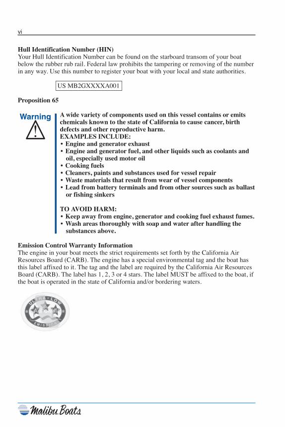
Hull Identification Number (HIN)Your Hull Identification Number can be found on the starboard transom of your boatbelow the rubber rub rail. Federal law prohibits the tampering or removing of the numberin any way. Use this number to register your boat with your local and state authorities.
US MB2GXXXXA001
Proposition 65
A wide variety of components used on this vessel contains or emitschemicals known to the state of California to cause cancer, birthdefects and other reproductive harm.EXAMPLES INCLUDE:• Engine and generator exhaust• Engine and generator fuel, and other liquids such as coolants and
oil, especially used motor oil• Cooking fuels• Cleaners, paints and substances used for vessel repair• Waste materials that result from wear of vessel components• Lead from battery terminals and from other sources such as ballast
or fishing sinkers
TO AVOID HARM:• Keep away from engine, generator and cooking fuel exhaust fumes.• Wash areas thoroughly with soap and water after handling the
substances above.
Emission Control Warranty InformationThe engine in your boat meets the strict requirements set forth by the California AirResources Board (CARB). The engine has a special environmental tag and the boat hasthis label affixed to it. The tag and the label are required by the California Air ResourcesBoard (CARB). The label has 1, 2, 3 or 4 stars. The label MUST be affixed to the boat, ifthe boat is operated in the state of California and/or bordering waters.
Chapter i_10:Chapter i.qxd 11/3/09 10:01 AM Page vi

vii
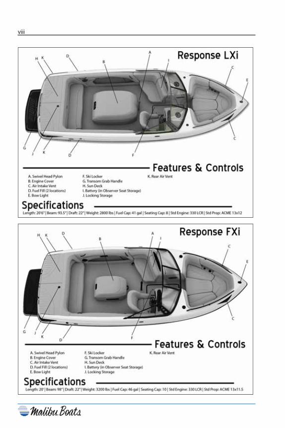
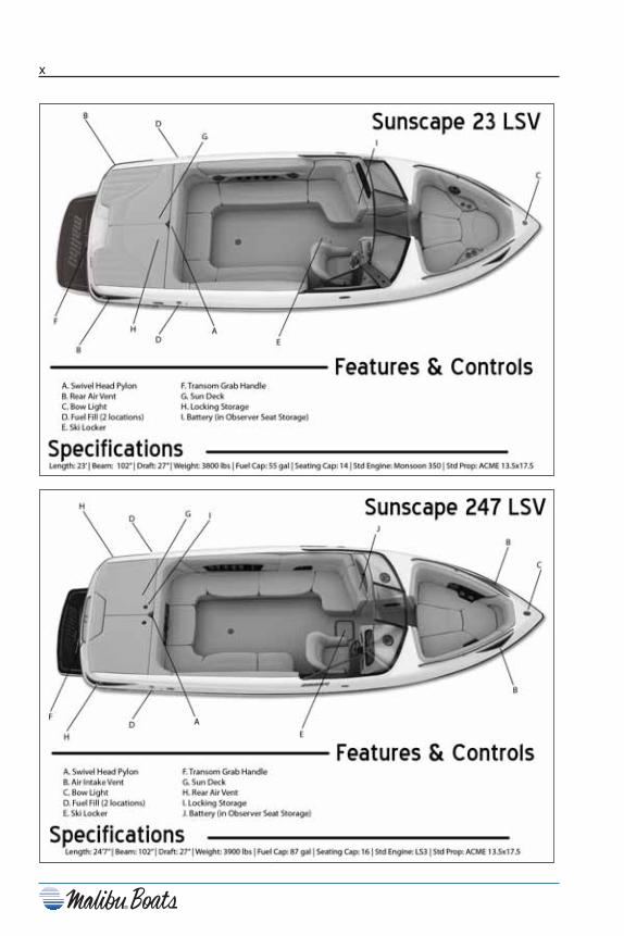
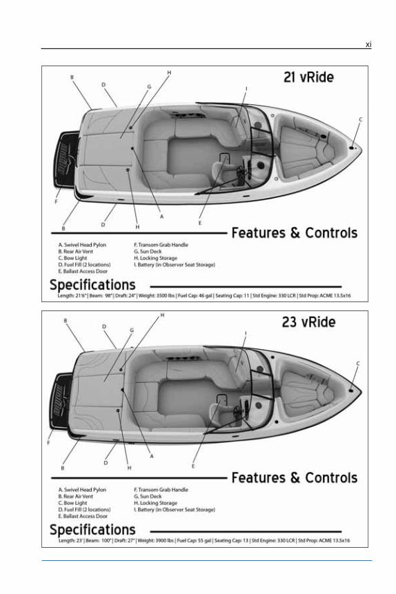
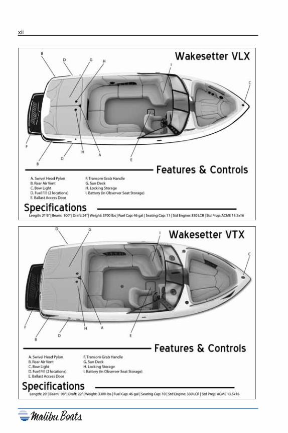
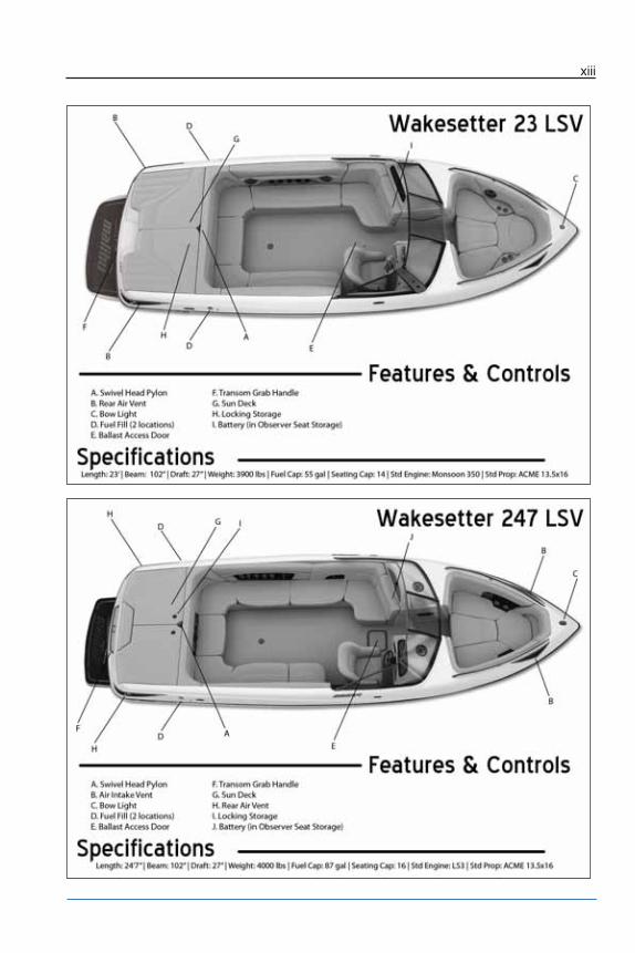
MODEL FEATURES &SPECIFICATIONS
Chapter i_10:Chapter i.qxd 11/3/09 10:01 AM Page vii
viii
Chapter i_10:Chapter i.qxd 11/12/09 4:14 PM Page viii

ix
Chapter i_10:Chapter i.qxd 11/3/09 10:01 AM Page ix
x
Chapter i_10:Chapter i.qxd 11/3/09 10:01 AM Page x
xi
Chapter i_10:Chapter i.qxd 11/12/09 4:14 PM Page xi
xii
Chapter i_10:Chapter i.qxd 11/12/09 4:14 PM Page xii
xiii
Chapter i_10:Chapter i.qxd 11/12/09 4:14 PM Page xiii

xiv
Notes
Chapter i_10:Chapter i.qxd 11/3/09 10:01 AM Page xiv

1-1
Chapter 1
BOATING SAFETYAt Malibu, safety is not an option!
General Precautions
Your Malibu boat has been constructed to meet all U.S. Coast Guard and National MarineManufacturers Association (NMMA) requirements. However, it is still yourresponsibility as the boat owner to ensure the boat is always operated in a safe fashion.
U.S. Coast Guard regulations require certain safety equipment be present on your boatduring operation. Besides the U.S. Coast Guard regulations, other local and/orinternational law enforcement agencies may have similar requirements. You should checkwith your local marine enforcement agency regarding any such requirements before usingthe waterways.
It is not intended for this manual to be a replacement for a course on boating safety. It ishighly recommended that if you are unfamiliar with the use and operation of a boat, youseek advice and training from a qualified individual or organization. Check with yourlocal boating agency or Malibu dealer for more information about boating safety classesin your area.
Safety Statements
Throughout this manual, specific precautions and symbols identify safety relatedinformation. Follow these precautions as indicated.
The Safety Alert symbol means Attention! Become Alert! Your Safety IsInvolved!
Indicates an imminently hazardous situation that, if notavoided, will result in death or serious injury.
Indicates a potentially hazardous situation that, if notavoided, could result in death or serious injury.
Indicates a potentially hazardous situation that, if not avoided,could result in minor or moderate injury or property damage. Itmay also be used to alert against unsafe practices.
Notice: Indicates installation, operation or maintenance informationwhich is important but not hazard related.
1
Chapter 1_10: Chapter 1 doc.qxd 11/3/09 10:18 AM Page 1

1-2
The precautions listed in this manual and on the boat are not all-inclusive. If a procedureor method is not specifically recommended, you must satisfy yourself that it is safe foryou and your passengers, and that the boat will not be damaged or made unsafe as a resultof your decision. Remember — always use common sense when operating your boat!
In an emergency situation, you may have to resort to measures which are not commonlypracticed. Always assess the dangers of being in harm’s way versus the protection ofequipment. Keep a sound mind during an emergency and always think safety.
Teak/Drag SurfingREAD, UNDERSTAND and be FAMILIAR with the information contained on anywarning labels or any label on equipment and adhere to the boat operation practicesdescribed on them. The United States Coast Guard issued a SAFETY ALERT on August28, 2001 that covers some of the issues of improper use of the boarding platform. TheSAFETY ALERT and portions of the accompanying information follow:
Every year tragic deaths occur from the negligence of unsafe boating and dangerousactivities. Experts say, “many of these deaths may have been caused by an invisiblehazard, carbon monoxide poisoning.” Taking the risk of swimming under a boardingplatform when the engine is running, skiing within 20 ft (6.1 meters), “teak surfing” or“dragging” behind a moving boat can be fatal.
Any dangerous activities which can result in a serious injury or death a water sport is notconsidered as a watersport by Malibu or DOES NOT promote unsafe boating risks orjeopardizing any boaters safety.
DO NOT use the boarding platform for any other purpose than boarding the boat orpreparation of entering the water, and DO NOT use the boarding platform when theengine is running.
SAFETY ALERT From August 28, 2001:The United States Coast Guard advised boaters not to “Teak/Drag Surf.” Recent boatingfatalities revealed that carbon monoxide (CO) emitted from a vessel’s exhaust resulted inCO poisoning and the death of at least six teak surfers. “Teak/Drag Surfing” places theindividual in position directly exposed to the CO in the engine’s exhaust. This may resultin a loss of coherent responses and even death. In addition, “Teak/Drag Surfing”dangerously exposes the individual to a possible propeller injury, and since it is donewithout a life jacket (PFD), it significantly increases the probability of drowning.Therefore, the Coast Guard stresses, “Teak/Drag Surfing” is a very dangerous activityand advises boaters not to participate in it.
The Coast Guard pointed out that carbon monoxide is one of the most dangerous gases. Itstrikes before you know you are exposed and it impairs in a way that can and too oftendoes lead to death. That is why it is so important to the Coast Guard that in everycircumstance where it can be avoided, it is.
Chapter 1_10: Chapter 1 doc.qxd 11/3/09 10:18 AM Page 2
1-3
Regulations
The U.S. Coast Guard is the governing authority of United States waterways and is thereto help the boating public. State boating regulations are enforced by local authorities. Youare subject to marine traffic laws and “Rules of the Road” for both federal and statewaterways; you must stop if signaled to do so by enforcement officers and permit to beboarded, if asked.
Responsibilities
RegistrationFederal Law requires that all motorboats be registered and that all motorcraft notdocumented by the U.S. Coast Guard display registration numbers. In nearly all states,this means registration with the designated state agency. In a few jurisdictions, the CoastGuard retains registration authority. Your Malibu dealer will either supply registrationforms or tell you where they may be obtained. The agency will supply you with acertificate which must be carried with you when the boat is in operation.
EducationIf you have never owned a boat before, you can get an excellent introduction to boathandling from organizations such as the U.S. Coast Guard, American Red Cross or yourlocal authority. Even if you are a veteran boater, these courses will help sharpen yourboating skills as well as bring you up to date on current rules and regulations. See yourlocal boating agency or Malibu dealer for information on classes in your area.
InsuranceThe boat owner is legally responsible for damages or injuries he or she causes. Commonsense dictates that you carry adequate personal liability and property damage insuranceon your boat, just as you would on your automobile. You should also protect yourinvestment from physical damage or theft.
Restricted AreasBefore boating, check with Local, State and Federal authorities to identify restrictedareas. Because of the threat of terrorism, the U.S. Coast Guard has and will continue toimplement strict limits on watercraft near U.S. Navy and Coast Guard ships and otherpotential targets.
Our EnvironmentAs a boater, you already appreciate nature’s beauty and the peace of the great outdoors. Itis a boater’s responsibility to protect the natural environment by keeping waterwaysclean. DO NOT put anything in the water you would not want to eat or drink!
Chapter 1_10: Chapter 1 doc.qxd 11/3/09 10:18 AM Page 3
1-4
Conserve Fishery ResourcesThere is a tremendous drain on our fishery resources. Over-fishing and pollution havestrained the fish population. Do your part by keeping only what you will eat by practicingcatch-and-release.
Foreign SpeciesIf you trailer your boat from lake to lake, you may unknowingly introduce a foreignaquatic species from one lake to the next. Thoroughly clean the bottom of the boat, belowthe water line, remove all weeds and algae, and drain the bilge and livewells beforelaunching the boat in a new body of water.
Fuel and Oil SpillageThe spilling of fuel or oil into our waterways contaminates the environment and isdangerous to wildlife. Never discharge or dispose fuel or oil into the water; it isprohibited and you could be fined. There are two common, accidental types of discharge:• Overfilling the fuel tank.• Pumping contaminated bilge water.
Fumes from rags can collect in bilge and be extremelyhazardous. Never store rags used to wipe up fuel or solventspills in the boat. Dispose of rags properly ashore.
Discharge and Disposal of WasteWaste means all forms of garbage, plastics, recyclables, food, wood, detergents, sewerageand even fish parts in certain waters - in short, nearly everything. We recommend youbring back everything you take out with you for proper disposal ashore.
Excessive NoiseNoise means engine noise, radio noise or even yelling. Many bodies of water haveadopted noise limits. Music and loud conversation can carry a considerable distance onwater, especially at night.
Wake and WashBe alert for NO WAKE zones. You are responsible for any damage or injury caused byyour wake/wash. Prior to entering a NO WAKE zone, come off plane to the sloweststeerable speed.
Exhaust EmissionsIncreased exhaust (hydrocarbon) emissions pollute our water and air. Keep your enginetuned and boat hull clean for peak performance. Consult your dealer and engine manualfor information.
PaintsIf your boat is kept in water where marine growth is a problem, the use of anti-foulingpaint may reduce the growth rate. Be aware of environmental regulations that may governyour paint choice. Contact your local boating authorities for information.
Chapter 1_10: Chapter 1 doc.qxd 11/3/09 10:18 AM Page 4
1-5
Cleaning AgentsHousehold cleaners should be used sparingly and not discharged into waterways. Nevermix cleaners and be sure to use plenty of ventilation in enclosed areas. DO NOT useproducts which contain phosphates, chlorine, solvents, non-biodegradable or petroleumbased products. Citrus based cleaners are excellent for marine cleaning purposes and aresafe for you and the environment. Refer to CARE AND MAINTENANCE for moreinformation.
Safety EquipmentU.S. Coast Guard regulations require certain accessory equipment on each boat. For adetailed description, obtain “Federal Requirements for Recreational Boats” published bythe Coast Guard.
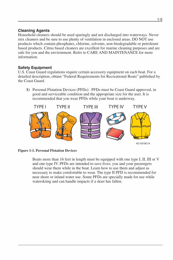
1) Personal Flotation Devices (PFDs): PFDs must be Coast Guard approved, ingood and serviceable condition and the appropriate size for the user. It isrecommended that you wear PFDs while your boat is underway.
Figure 1-1. Personal Flotation Devices
Boats more than 16 feet in length must be equipped with one type I, II, III or Vand one type IV. PFDs are intended to save lives; you and your passengersshould wear them while in the boat. Learn how to use them and adjust asnecessary to make comfortable to wear. The type II PFD is recommended fornear shore or inland water use. Some PFDs are specially made for use whilewaterskiing and can handle impacts if a skier has fallen.
KC-0318C-A
TYPE I TYPE II TYPE III TYPE IV TYPE V
Chapter 1_10: Chapter 1 doc.qxd 11/3/09 10:18 AM Page 5
1-6
Notice: If a type V PFD is to be counted toward the minimum carriagerequirements, it must be worn.
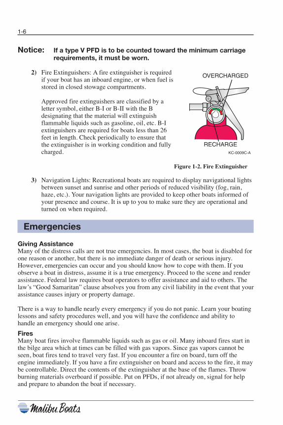
2) Fire Extinguishers: A fire extinguisher is requiredif your boat has an inboard engine, or when fuel isstored in closed stowage compartments.
Approved fire extinguishers are classified by aletter symbol, either B-I or B-II with the Bdesignating that the material will extinguishflammable liquids such as gasoline, oil, etc. B-Iextinguishers are required for boats less than 26feet in length. Check periodically to ensure thatthe extinguisher is in working condition and fullycharged.
Figure 1-2. Fire Extinguisher
3) Navigation Lights: Recreational boats are required to display navigational lightsbetween sunset and sunrise and other periods of reduced visibility (fog, rain,haze, etc.). Your navigation lights are provided to keep other boats informed ofyour presence and course. It is up to you to make sure they are operational andturned on when required.
Emergencies
Giving AssistanceMany of the distress calls are not true emergencies. In most cases, the boat is disabled forone reason or another, but there is no immediate danger of death or serious injury.However, emergencies can occur and you should know how to cope with them. If youobserve a boat in distress, assume it is a true emergency. Proceed to the scene and renderassistance. Federal law requires boat operators to offer assistance and aid to others. Thelaw’s “Good Samaritan” clause absolves you from any civil liability in the event that yourassistance causes injury or property damage.
There is a way to handle nearly every emergency if you do not panic. Learn your boatinglessons and safety procedures well, and you will have the confidence and ability tohandle an emergency should one arise.
FiresMany boat fires involve flammable liquids such as gas or oil. Many inboard fires start inthe bilge area which at times can be filled with gas vapors. Since gas vapors cannot beseen, boat fires tend to travel very fast. If you encounter a fire on board, turn off theengine immediately. If you have a fire extinguisher on board and access to the fire, it maybe controllable. Direct the contents of the extinguisher at the base of the flames. Throwburning materials overboard if possible. Put on PFDs, if not already on, signal for helpand prepare to abandon the boat if necessary.
OVERCHARGED
RECHARGEKC-0009C-A
Chapter 1_10: Chapter 1 doc.qxd 11/3/09 10:18 AM Page 6

1-7
Reporting AccidentsBoat operators are required by law to file a Boating Accident report with their stateboating law enforcement agency or local authority when their boat is involved in certainboating accidents. A boating accident must be reported if there is a loss or probable lossof life, personal injury requiring medical attention, damage exceeding $500, or there is acomplete loss of the boat. If any of these conditions arise, seek further assistance fromlocal law enforcement personnel.
Hazardous Conditions
Every waterway poses hazards that should be avoided. The following informationoutlines some of the hazards which may be encountered.
WeatherLearn and understand weather patternsand signs of change. Bad weather cancause an uncomfortable and unsafesituation. If a storm approaches, seek asafe harbor.
Figure 1-3. Weather Hazards
Dam SpillwaysThe area around dam spillways is very hazardous and conditions can change rapidly. Stayclear of the spillways and areas below dams.
WeedsWeeds can generally be a threat to a boat’s engine and other components on the boat. Ifweeds wrap around the propeller, they can create vibration in the engine. They alsorestrict water intake, causing the engine to overheat.
Shallow Water OperationShallow water brings on obvious hazards such as sand bars, stumps, rocks, etc. Know thearea you will be operating the boat in. Hitting objects at high speeds can cause severedamage to people and the boat. If you know you will be navigating the boat in shallowwater, post a lookout and proceed slowly.
Know the minimal depth your boat can safely travel.
Chapter 1_10: Chapter 1 doc.qxd 11/3/09 10:18 AM Page 7
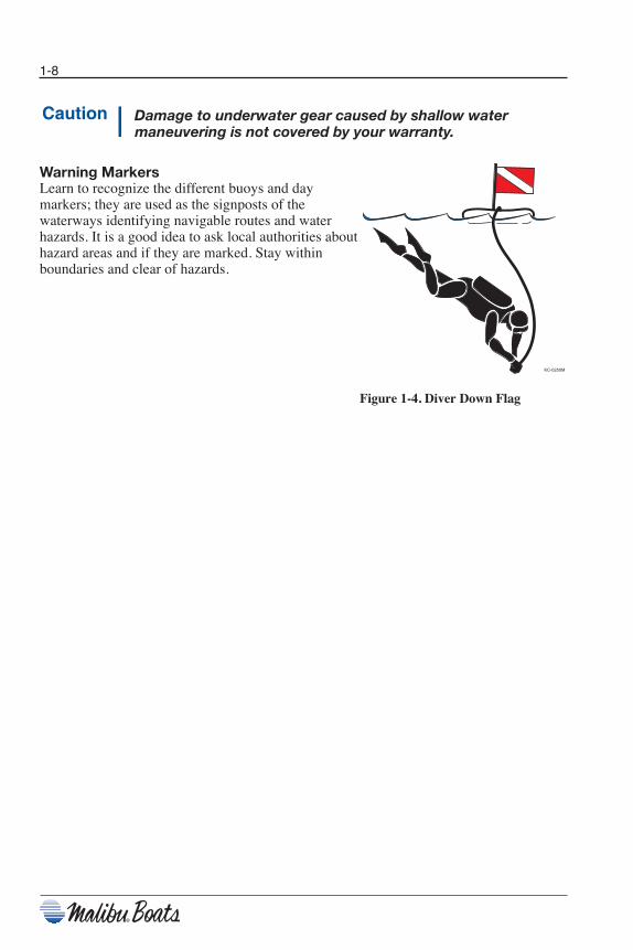
Damage to underwater gear caused by shallow watermaneuvering is not covered by your warranty.
Warning MarkersLearn to recognize the different buoys and daymarkers; they are used as the signposts of thewaterways identifying navigable routes and waterhazards. It is a good idea to ask local authorities abouthazard areas and if they are marked. Stay withinboundaries and clear of hazards.
Figure 1-4. Diver Down Flag
1-8
KC-0250M
Chapter 1_10: Chapter 1 doc.qxd 11/3/09 10:18 AM Page 8

1-9
Carbon Monoxide
Carbon Monoxide (CO) is a colorless and odorless gas produced by all engines and fuelburning appliances. Even with the best boat design and construction, plus the utmost carein inspection, operation and maintenance, hazardous levels of CO may still be present inaccommodation spaces under certain conditions. To reduce CO accumulation, alwaysventilate the boat interior and avoid boating situations which cause increased exposure.
EXTREME HAZARD – Carbon monoxide gas (CO) is colorless,odorless and extremely dangerous. All engines and fuelburning appliances produce CO as exhaust. Direct andprolonged exposure to CO will cause BRAIN DAMAGE orDEATH. Signs of exposure to CO include nausea, dizzinessand drowsiness. Sources of CO include:
Figure 1-5. Carbon Monoxide Hazards
Chapter 1_10: Chapter 1 doc.qxd 11/3/09 10:18 AM Page 9
1-10
Operation by Minors
If your boat will be operated by a minor, remember to have an adult present at all times.Many states have laws regarding minimum age and licensing requirements for minors.Contact state and local authorities for special requirements that may apply in your area.
Passenger Safety
Any time you take your boat out, make sure that there is at least one other passengeraboard who is familiar with the operation of your boat. Passengers should be well awareof emergency equipment and shown how to use it. Passengers should also keep hands andfeet in the boat and be safely seated while the boat is in motion.
Your boat should never be operated while you are under the influence of alcohol or drugs.Reaction times can be reduced and judgment affected creating situations that can be verydangerous.
Federal and state laws prohibit operating a boat under theinfluence of alcohol and other drugs. These regulations areactively enforced. Impaired operation may result in severepersonal injury or death.
Basic Rules of the Road
The nautical rules of the road must be followed to preventcollisions between vessels. Like traffic laws for automobiles,the operator is legally required to follow the rules.
The following information outlines only the most basic of the nautical rules of the road.For more information, contact your local U.S. Coast Guard Auxiliary or local maritimeauthority.
Aids to NavigationLearn to recognize the different buoys and day markers; they are the signposts of thewaterways. The United States Aids to Navigation System (USATONS) is the primarymarking system used on inland water, coastal waters and rivers in the United States. Thissystem is maintained by the U.S. Coast Guard (USCG).
Chapter 1_10: Chapter 1 doc.qxd 11/3/09 10:18 AM Page 10
1-11
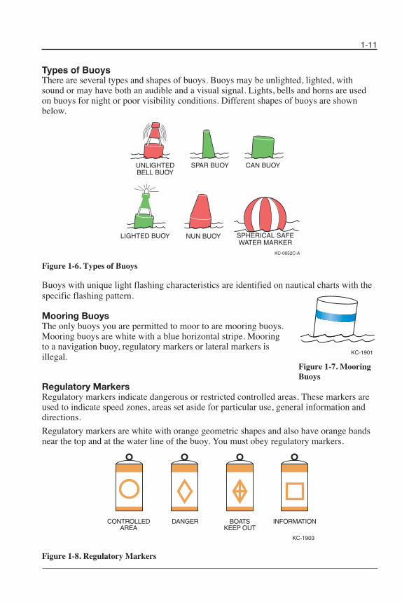
Types of BuoysThere are several types and shapes of buoys. Buoys may be unlighted, lighted, withsound or may have both an audible and a visual signal. Lights, bells and horns are usedon buoys for night or poor visibility conditions. Different shapes of buoys are shownbelow.
Figure 1-6. Types of Buoys
Buoys with unique light flashing characteristics are identified on nautical charts with thespecific flashing pattern.
Mooring BuoysThe only buoys you are permitted to moor to are mooring buoys. Mooring buoys are white with a blue horizontal stripe. Mooring to a navigation buoy, regulatory markers or lateral markers is illegal.
Figure 1-7. MooringBuoys
Regulatory MarkersRegulatory markers indicate dangerous or restricted controlled areas. These markers areused to indicate speed zones, areas set aside for particular use, general information anddirections.
Regulatory markers are white with orange geometric shapes and also have orange bandsnear the top and at the water line of the buoy. You must obey regulatory markers.
Figure 1-8. Regulatory Markers
CONTROLLEDAREA
DANGER BOATSKEEP OUT
INFORMATION
KC-1903
SPHERICAL SAFEWATER MARKER
UNLIGHTEDBELL BUOY
LIGHTED BUOY
CAN BUOYSPAR BUOY
NUN BUOY
KC-0052C-A
KC-1901
Chapter 1_10: Chapter 1 doc.qxd 11/3/09 10:18 AM Page 11

1-12
Right-of-Way
Notice: In general, boats with less maneuverability have right-of-wayover more agile craft. You must stay clear of the vessel withright-of-way and pass to his stern.
Privileged BoatsPrivileged boats have right-of-way and can hold course and speed. Sailboats and boats paddled or rowed have the right-of-way over motor boats. Sailboats under power are considered motorboats. Small pleasure craft must yield to large commercial boats in narrow channels.
Burdened BoatsThe burdened boat is the boat that must make what ever adjustments to course and speed necessary to keep out of the way of the privileged boat.
Crossing SituationIn crossing situations, the boat to the right from the 12 o’clock to the 4 o’clock position has the right-of-way. It must hold course and speed. The burdened boat keeps passes behind the privileged boat. Boats going up and down ariver have the privilege over boatscrossing the river.
Meeting Head-OnNeither boat has the right-of-way in this situation. Both boats should decrease speed,should turn to the right and pass port-to-port. However, if both boats are on the left sideof a channel, each vessel should sound two short horn blasts and pass starboard tostarboard.
KC-0194C-A
BURDENEDVESSEL
DANGER ZONE
PRIVILEGEDVESSEL
12 O'CLOCK
4 O'CLOCK
Figure 1-9. Crossing Situation
Chapter 1_10: Chapter 1 doc.qxd 11/3/09 10:18 AM Page 12
1-13
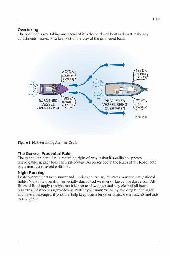
OvertakingThe boat that is overtaking one ahead of it is the burdened boat and must make anyadjustments necessary to keep out of the way of the privileged boat.
Figure 1-10. Overtaking Another Craft
The General Prudential RuleThe general prudential rule regarding right-of-way is that if a collision appearsunavoidable, neither boat has right-of-way. As prescribed in the Rules of the Road, bothboats must act to avoid collision.
Night RunningBoats operating between sunset and sunrise (hours vary by state) must use navigationallights. Nighttime operation, especially during bad weather or fog can be dangerous. AllRules of Road apply at night, but it is best to slow down and stay clear of all boats,regard less of who has right-of-way. Protect your night vision by avoiding bright lightsand have a passenger, if possible, help keep watch for other boats, water hazards and aidsto navigation.
PRIVILEGEDVESSEL BEING
OVERTAKEN
BURDENEDVESSEL
OVERTAKING
HORN(SHORT BLAST)
HORN(SHORT BLAST)
HORN(2 SHORTBLASTS)
HORN(2 SHORTBLASTS)
KC-0196C-B
Chapter 1_10: Chapter 1 doc.qxd 11/3/09 10:18 AM Page 13

1-14
Notes
Chapter 1_10: Chapter 1 doc.qxd 11/3/09 10:18 AM Page 14

Chapter 2
GAUGES & CONTROLSNo other ski boat manufacturer incorporates in their product as many innovative and technically advanced features as Malibu.
Standard Gauges
The following gauges are included on all models. It is important for the safe and properoperation of your boat to fully understand these gauges.
Malibu In-Dash Graphical Display
Figure 2-1. Graphical Display
Figure 2-2. MaliView Dash
2-1
2
Chapter 2_10: Chapter 2 doc.qxd 11/3/09 11:48 AM Page 1
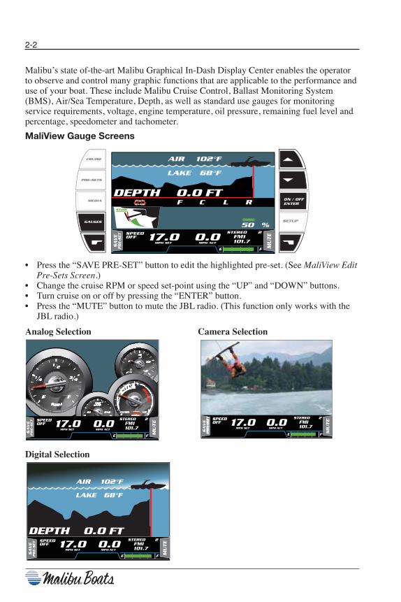
Malibu’s state of-the-art Malibu Graphical In-Dash Display Center enables the operatorto observe and control many graphic functions that are applicable to the performance anduse of your boat. These include Malibu Cruise Control, Ballast Monitoring System(BMS), Air/Sea Temperature, Depth, as well as standard use gauges for monitoringservice requirements, voltage, engine temperature, oil pressure, remaining fuel level andpercentage, speedometer and tachometer.
MaliView Gauge Screens
• Press the “SAVE PRE-SET” button to edit the highlighted pre-set. (See MaliView EditPre-Sets Screen.)
• Change the cruise RPM or speed set-point using the “UP” and “DOWN” buttons.• Turn cruise on or off by pressing the “ENTER” button.• Press the “MUTE” button to mute the JBL radio. (This function only works with the
JBL radio.)
SETUP
CRUISE
PRE-SETS
MEDIA ON / OFFENTER
HPM TES17.0
MPH ACT0.0SPEED
OFFSTEREO 2 FM1 101.7
E F MUTE
AIR 102 °F
86 F° EKAL
0.0DEPTH FT
05 %
F C L RSTOW
SA
VE
PR
E-SET
GAUGES
2-2
Analog Selection
Digital Selection
Camera Selection
HPM TES17.0
HPM TCA0.0SPEED
OFFSTEREO 2 FMI 101.7
E F MUTE
SA
VE
PRE-S
ET
PRE-S
ET
AIR 102 °F
86 F° LAKE
0.0DEPTH FT
MPH SET17.0
HPM TCA0.0SPEED
OFFSTEREO 2 FMI 101.7
E F MU
TE
SA
VE
PR
E-S
ET
HPM TES17.0
MPH ACT0.0SPEED
OFFSTEREO 2 FM1 101.7
E F MUTE
SA
VE
PRE-S
ET
Chapter 2_10: Chapter 2 doc.qxd 11/3/09 11:48 AM Page 2
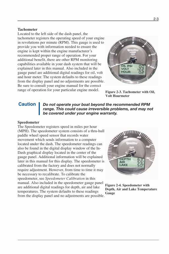
Tachometer Located to the left side of the dash panel, the tachometer registers the operating speed of your enginein revolutions per minute (RPM). This gauge is used toprovide you with information needed to ensure theengine is kept within the engine manufacturer’srecommended proper range of operation. For youradditional benefit, there are other RPM monitoringcapabilities available in your dash system that will beexplained later in this manual. Also included in thegauge panel are additional digital readings for oil, voltand hour meter. The system defaults to these readingsfrom the display panel and no adjustments are possible.Be sure to consult your engine manual for the correctrange of operation for your particular engine model.
Do not operate your boat beyond the recommended RPMrange. This could cause irreversible problems, and may notbe covered under your engine warranty.
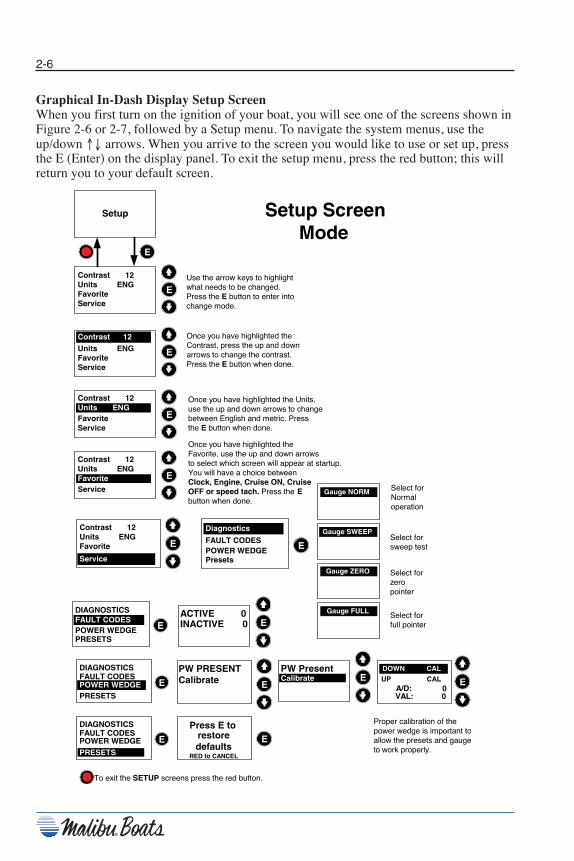
SpeedometerThe Speedometer registers speed in miles per hour (MPH). The speedometer system consists of a thru-hullpaddle wheel speed sensor that records watermovement which sends information to a computerlocated under the dash. The speedometer readings canalso be found in the digital display window of the In-Dash graphical display located in the center of thegauge panel. Additional information will be explainedlater in this manual for this display. The speedometer iscalibrated from the factory and does not normallyrequire adjustment. However, from time to time it maybe necessary to recalibrate. To calibrate thespeedometer, see Speedometer Calibration in thismanual. Also included in the speedometer gauge panelare additional digital readings for depth, air and laketemperatures. The system defaults to these readingsfrom the display panel and no adjustments are possible.
2-3
Figure 2-3. Tachometer with Oil,Volt Hourmeter
Figure 2-4. Speedometer withDepth, Air and Lake TemperatureGauge
Chapter 2_10: Chapter 2 doc.qxd 11/3/09 11:48 AM Page 3

Figure 2-5. Dash Gauges
Engine TemperatureThe temperature gauge is located at the lower center left bottom panel of the dash display.The temperature gauge indicates the temperature of the water/coolant inside the engine.The proper operating range for your engine is between 140 – 160º F. All engines areequipped with an engine control module that will cause the engine to run at reducedspeeds (power reduction mode) if the engine is running above recommended operationtemperatures. If you notice that your speed has reduced during normal running operationwithout reducing the throttle, monitor your temperature gauge. If your temperature gaugeindicates excessive temperatures, slow down immediately and turn off engine.Continuing to operate the boat while the temperature is above normal operatingparameters may cause serious damage to your engine.
Oil PressureThe oil pressure gauge is located at the lower center of the bottom panel of the dashdisplay. The oil pressure gauge indicates the oil pressure in the engine while the engine isrunning and is measured in pounds per square inch (psi). Oil pressure may vary withengine speed, outside temperatures, oil viscosity and other environmental factors. If theoil pressure reading is below the normal range, you should stop your engine and checkyour oil immediately.
Average pressure ranges are between 6 psi at 1000 RPM and 80 psi at cruising speeds. Ifyou are experiencing low oil pressure, stop your engine and check your oil beforeoperating again.
Do not continue to run engine if pressure is low. If you do theengine can become so hot that the surrounding componentscould catch fire.
Notice: Damage caused from neglected oil problems can be costly.Such damage is not covered by your warranty.
2-4
Chapter 2_10: Chapter 2 doc.qxd 11/3/09 11:48 AM Page 4

2-5
FuelThe fuel gauge is located at the lower center right bottom panel of the dash display. Thefuel gauge indicates the approximate quantity of fuel remaining in the tank when theignition is in the “On” position. Although your fuel tank will still have some fuelremaining even though the gauge reads empty, it is recommended that the tank be filledwhen the gauges indicates 1/4 full.
Do not top off tank.
Notice: It is not uncommon during operation of your boat for the fuelgauge to register slightly different amounts than what isactually in the tank. This is normal operation and does notindicate a problem. The fuel gauge will read most accuratewhen sitting still in calm water.
Malibu Graphical In-Dash DisplayAll 2010 boats will include the Malibu Graphical In-Dash Display as a standard feature.This display can be found in the center of your dash console behind the steering wheel.Information is displayed in digital format for easy to read information, navigable usingthe Function up ↑ arrow, or Function down ↓ arrow followed by pressing the Enter (E)button in the center right of the display panel. The Graphical Display includes thesefeatures: Malibu Cruise, Ballast Monitoring System (BMS) “Available in wakeboardmodels only,” Air/Sea Temp, Depth meter, Power Wedge and service.
Figure 2-6. In-Dash Display
Figure 2-7. MaliView In-Dash Display
Chapter 2_10: Chapter 2 doc.qxd 11/3/09 11:48 AM Page 5
2-6
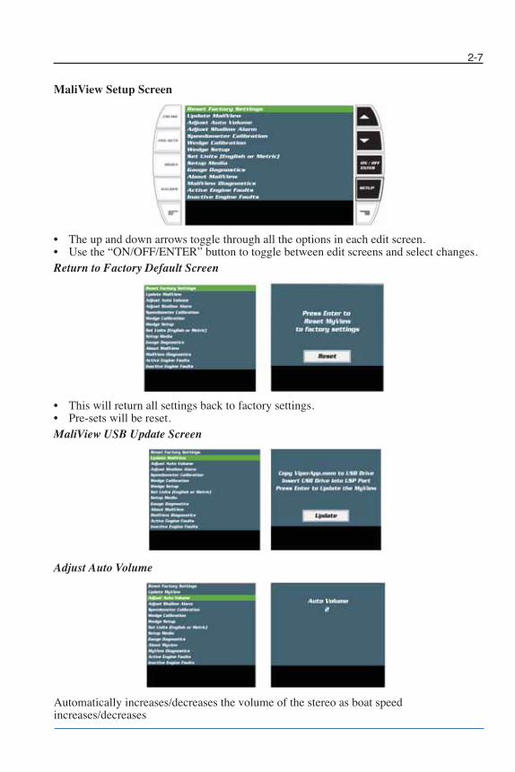
Graphical In-Dash Display Setup ScreenWhen you first turn on the ignition of your boat, you will see one of the screens shown inFigure 2-6 or 2-7, followed by a Setup menu. To navigate the system menus, use theup/down ↑↓ arrows. When you arrive to the screen you would like to use or set up, pressthe E (Enter) on the display panel. To exit the setup menu, press the red button; this willreturn you to your default screen.
Use the arrow keys to highlightwhat needs to be changed.Press the E button to enter intochange mode.
Once you have highlighted theContrast, press the up and downarrows to change the contrast.Press the E button when done.
Once you have highlighted the Units,use the up and down arrows to changebetween English and metric. Pressthe E button when done.
Once you have highlighted theFavorite, use the up and down arrowsto select which screen will appear at startup.You will have a choice betweenClock, Engine, Cruise ON, CruiseOFF or speed tach. Press the Ebutton when done.
Setup ScreenMode
Select forNormaloperation
Select forsweep test
Select forzeropointer
Select forfull pointer
To exit the SETUP screens press the red button.
Gauge NORM
Gauge SWEEP
Gauge ZERO
Gauge FULL
Setup
E
Contrast 12Units ENGFavoriteService
E
Contrast 12Units ENGFavoriteService
Contrast 12
E
Contrast 12Units ENGFavoriteService
Units ENG
E
Contrast 12Units ENGFavoriteService
E
Favorite
Contrast 12Units ENGFavoriteService
E
Service
Diagnostics
EFAULT CODESPOWER WEDGEPresets
ACTIVE 0INACTIVE 0FAULT CODES
E
DIAGNOSTICS
POWER WEDGEPRESETS
E
PW PRESENTCalibratePOWER WEDGE E
DIAGNOSTICSFAULT CODES
PRESETSE
PW PresentCalibrate E
POWER WEDGE E
DIAGNOSTICSFAULT CODES
PRESETS
Press E torestoredefaults
RED to CANCEL
E
DOWN CAL
UP CAL A/D: 0 VAL: 0
E
Proper calibration of thepower wedge is important toallow the presets and gaugeto work properly.
Chapter 2_10: Chapter 2 doc.qxd 11/3/09 11:48 AM Page 6
2-7
MaliView Setup Screen
• The up and down arrows toggle through all the options in each edit screen.• Use the “ON/OFF/ENTER” button to toggle between edit screens and select changes.Return to Factory Default Screen
• This will return all settings back to factory settings.• Pre-sets will be reset.MaliView USB Update Screen
Adjust Auto Volume
Automatically increases/decreases the volume of the stereo as boat speedincreases/decreases
Chapter 2_10: Chapter 2 doc.qxd 11/3/09 11:49 AM Page 7

2-8
Depth Level Alarm Screen
Speed Calibration Screen
Wedge Calibration Screen
Wedge Setup Screen
English Metric Mode (English or Metric Conversion)
Chapter 2_10: Chapter 2 doc.qxd 11/3/09 11:49 AM Page 8

2-9
Video ON/OFF Setup
Turns on or off all available video screens
Gauge Diagnostic Mode (Gauge Sweep Mode Test)
Current Software Version
System Diagnostic Screen
Active and Inactive Engine Fault Screen
Chapter 2_10: Chapter 2 doc.qxd 11/3/09 11:49 AM Page 9

2-10
MALIBU PRE-SETSHow to Use the Malibu Pre-Sets
The Malibu pre-sets Save, Store and Control 3 different parameters:• 1 – Boat Speed/Cruise Control• 2 – Wedge Angle/Boat Angle Control• 3 – Ballast Level
The system is easy to operate once you understand what you are controlling and knowwhat to expect from it. It will require that you read the instructions and spend a little timelearning how to save and edit the pre-sets to get the full benefit of the system.
The factory pre-sets are the same settings for every boat. These were developed andintended to only be a starting point for customers to use as a guide to get close to propersetup for each boat. Due to the large variety of hull shapes, boat lengths, engine choices,prop choices, and boat loading it is nearly impossible to put together factory pre-sets thatwork the same on every boat. For this reason we chose a “middle of the road” setting andworked to create an easy method to modify the factory pre-sets and create individual pre-sets. The factory default pre-sets will perform different on different boats. It is highlyrecommended that you get the instructions and spend some time on the water in yourboat. Creating the perfect wake requires managing the weight distribution in and aroundthe boat. This is why the pre-sets are adjustable.
The system has 7 factory defaults pre-programmed in. These are just basically a sampleof what the system can do. They are a starting point to developing your perfect wake inyour boat. They will not be the perfect wake for your boat right out of the box.
If you ever hit restore factory defaults, or have the dealer replace or re-flash the MMDC,you will lose all saved pre-set parameters and will need to edit the pre-sets again and savethem.
Chapter 2_10: Chapter 2 doc.qxd 11/3/09 11:49 AM Page 10
2-11
Chapter 2_10: Chapter 2 doc.qxd 11/3/09 11:49 AM Page 11

2-12
MaliView Pre-Sets Screen
• Enter pre-sets using the “PRE-SETS” button.• Press the “EDIT PRE-SET” button to edit the highlighted pre-set. (See MaliView Edit
Pre-Sets Screen.)• The up and down arrows will allow you to highlight the desired pre-set.• Use the “ON/OFF/ENTER” button to select and activate pre-set.
NOTES:• The only way to stop a pre-set is to turn off “CRUISE.”• Auto Wedge can only be turned on or off in the setup screen.• Make sure you have a calibrated power wedge for correct operation.• Ballast bars will disappear when the sensor is not present.• The engine must be running for the wedge to move to a pre-set position.
SETUP
CRUISE
GAUGES
PRE-SETS
CRUISE
MEDIA ON / OFFENTER
EDITPRE-SET
1000%
HALEY WAKEBOARD
F C L R MLSRIDER
21.8
1000%
ED SURF LEFT
9.8
1000%
BLANKMPH
15.0
STOW
STOW
STOW
1000%
HALEY WAKEBOARD
F C L R MLSRIDER
21.8 STOW
Rider’s selected
picture
Pre-set name
Pre-set Saved Speed set point
Ballast Pre-set set points
Power Wedge Pre-setset point
Indicates the wake shaping zone
Chapter 2_10: Chapter 2 doc.qxd 11/3/09 11:49 AM Page 12
2-13
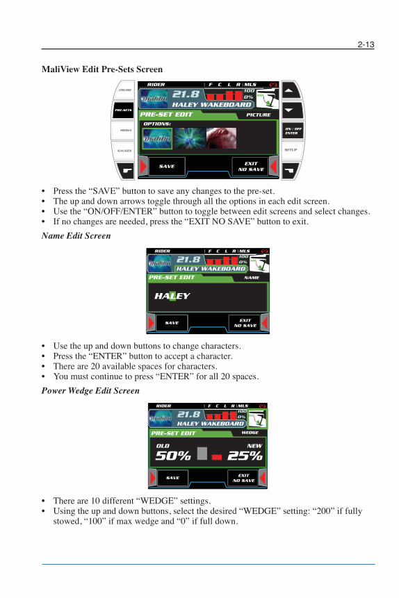
MaliView Edit Pre-Sets Screen
• Press the “SAVE” button to save any changes to the pre-set.• The up and down arrows toggle through all the options in each edit screen.• Use the “ON/OFF/ENTER” button to toggle between edit screens and select changes.• If no changes are needed, press the “EXIT NO SAVE” button to exit.
Name Edit Screen
• Use the up and down buttons to change characters.• Press the “ENTER” button to accept a character.• There are 20 available spaces for characters.• You must continue to press “ENTER” for all 20 spaces.
Power Wedge Edit Screen
• There are 10 different “WEDGE” settings.• Using the up and down buttons, select the desired “WEDGE” setting: “200” if fully
stowed, “100” if max wedge and “0” if full down.
SETUP
CRUISE
GAUGES
PRE-SETS
CRUISE
MEDIA ON / OFFENTER
SAVEEXIT
NO SAVE
PRE-SET EDIT MLS FRONT
25%60%OLD NEW
SAVEEXIT
NO SAVE
PRE-SET EDIT PICTURE
OPTIONS:
1000%
HALEY WAKEBOARD
F C L R MLSRIDER
21.8 STOW
SAVEEXIT
NO SAVESAVE
EXITNO SAVE
PRE-SET EDIT NAME
HALEY
1000%
HALEY WAKEBOARD
F C L R MLSRIDER
21.8 STOW
SAVEEXIT
NO SAVESAVE
EXITNO SAVE
PRE-SET EDIT WEDGE
20.2
PRE-SET EDIT WEDGE
25%50%OLD NEW
1000%
HALEY WAKEBOARD
F C L R MLSRIDER
21.8 STOW
Chapter 2_10: Chapter 2 doc.qxd 11/3/09 11:49 AM Page 13
2-14
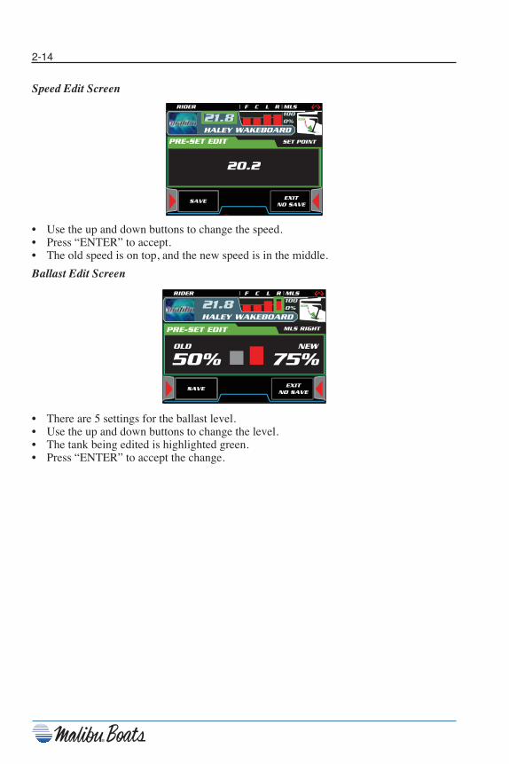
Speed Edit Screen
• Use the up and down buttons to change the speed.• Press “ENTER” to accept.• The old speed is on top, and the new speed is in the middle.
Ballast Edit Screen
• There are 5 settings for the ballast level.• Use the up and down buttons to change the level.• The tank being edited is highlighted green.• Press “ENTER” to accept the change.
SAVEEXIT
NO SAVESAVE
EXITNO SAVE
PRE-SET EDIT SET POINT
20.2
1000%
HALEY WAKEBOARD
F C L R MLSRIDER
21.8 STOW
SAVEEXIT
NO SAVESAVE
EXITNO SAVE
PRE-SET EDIT WEDGE
20.2
PRE-SET EDIT MLS RIGHT
75%50%OLD NEW
1000%
HALEY WAKEBOARD
F C L R MLSRIDER
21.8 STOW
Chapter 2_10: Chapter 2 doc.qxd 11/3/09 11:49 AM Page 14
2-15
Boat Alarms and Engine FaultsMalibu Boats are equipped with two separate computers connected to many sensors andcontrollers that constantly monitor various functions of the boat and engine. Certainfunctions, if outside of a pre-determined operational parameters, may activate an alarm.When an alarm is activated, you will hear an audible buzzer alarm and see an alarmindicator in the Multi-Function LCD display. Both the engine’s Electronic ControlModule (ECM) and the dash Medallion Instrumentation Computer (M3) have the abilityto activate an alarm.
If the Medallion Instrumentation Computer (M3) activates the alarm, you will see exactlywhat the fault description is in the display, such as low oil pressure, high coolant temp,low or high system voltage Depth alarm and Power Wedge over-speed. The M3 monitorsthese sensors independently of the ECM via the CAN link. Additional alarm parametersmay be added.
The Indmar engine for 2010 is equipped with the E-Control New Engine Control Modulewith OBD-M. If the engine ECM activates an alarm you will ether see “Engine Fault” or“Service Required”. “Service Required” will only be seen on engines equipped withCatalysts Emissions System for the CARB (California Air Resources Board) and EPArequirements as of June 30, 2006.
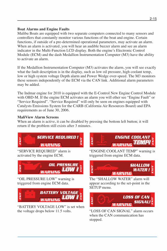
MaliView Alarm ScreensWhen an alarm is active, it can be disabled by pressing the bottom left button; it willreturn if the problem still exists after 3 minutes.
“SERVICE REQUIRED” alarm isactivated by the engine ECM.
“OIL PRESSURE LOW” warning istriggered from engine ECM data.
“BATTERY VOLTAGE LOW” is set whenthe voltage drops below 11.5 volts.
“ENGINE COOLANT TEMP” warning istriggered from engine ECM data.
The “SHALLOW WATER” alarm willappear according to the set-point in theSETUP menu.
“LOSS OF CAN SIGNAL” alarm occurswhen the CAN communication hasstopped.
EXIT
EXIT
SERVICE REQUIRED !
WARNING
EXIT
EXIT
OIL PRESSURE
WARNING
EXIT
EXIT
BATTERY VOLTAGE
WARNING
EXIT
EXIT
ENGINE COOLANTTEMP!WARNING
EXIT
EXIT
SHALLOW
WARNINGWATER !
EXIT
EXIT
LOSS OF CAN
WARNINGSIGNAL!
Chapter 2_10: Chapter 2 doc.qxd 11/3/09 11:49 AM Page 15
2-16
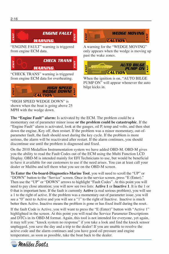
“ENGINE FAULT” warning is triggeredfrom engine ECM data.
“CHECK TRANS” warning is triggeredfrom engine ECM data for overheating.
“HIGH SPEED WEDGE DOWN” isshown when the boat is going above 25MPH with the wedge down.
A warning for the “WEDGE MOVING”only appears when the wedge is moving uppast the wake zones.
When the ignition is on, “AUTO BILGEPUMP ON” will appear whenever the autobilge kicks in.
EXIT
EXIT
ENGINE FAULT
WARNING
EXIT
EXIT
CHECK TRANS
WARNINGEXIT
CAUTION
HIGH SPEEDWEDGE DOWN!
EXIT
EXIT
CAUTION
WEDGE MOVING
EXIT
EXIT
EXIT
CAUTION
AUTO BILGEPUMP ON
The “Engine Fault” alarm: Is activated by the ECM. The problem could be amomentary out of parameter minor issue or the problem could be catastrophic. If the“Engine Fault” alarm is activated, look at the gauges, oil P, temp and volts, and then shutdown the engine, Key off, then restart. If the problem was a minor momentary, out-of-parameter fault, the fault should reset during the key cycle. If the problem is moreserious, the alarm will be reactivated after restart. If the alarm continues, you shoulddiscontinue use until the problem is diagnosed and fixed.
On the 2010 Medallion Instrumentation system we have added OBD-M. OBD-M givesyou the ability to read the Fault Codes out of the ECM using the Multi Function LCDDisplay. OBD-M is intended mainly for EFI Technicians to use, but would be beneficialto have it available for our customers to use if the need arises. You can at least call yourdealer or Malibu and tell them what you see on the OBD-M screen.
To Enter the On-board-Diagnostics-Marine Tool, you will need to scroll the “UP” or“DOWN” button to the “Service” screen. Once in the service screen, press “E (Enter).”Then use the “UP” or “DOWN” arrows to highlight “Fault Codes”. At this point you willneed to pay close attention; you will now see two lists: Active 1 or Inactive 1. It is the 1 or0 that is important here. If the fault is currently Active (a real serious problem), you will seea 1 to the right of active. If the problem was a momentary out of parameter issue, you willsee a “0” next to Active and you will see a “1” to the right of Inactive. Inactive is muchbetter then Active. Inactive means the problem is gone or has fixed itself during the reset.
If the fault Code is Active, you will want to press the “E (Enter)” button with “Active 1”highlighted in the screen. At this point you will read the Service Parameter Descriptionsand DTCs in its OBD-M format. Again, this tool is not intended for everyone, yet again,it may tell you: “knock system no response” if you take a look and find the knock sensorunplugged, you save the day and a trip to the dealer! If you are unable to resolve theactive code and the alarm continues and you have good oil pressure and enginetemperature, as soon as possible, take the boat back to the dealer.
Chapter 2_10: Chapter 2 doc.qxd 11/3/09 11:49 AM Page 16
2-17
Service Required Alarm: The Monsoon Engine equipped with Catalyst Emissionssystem is the only engine you could see “Service Required” on. Service Requiredparameters are all based on “emissions related faults”. Several of the typical sensors arenow part of the emissions related faults, such as the Knock system and Ignition Controlsystem as well as the oxygen sensors and Catalyst Monitoring system. Be advised: PerEPA and CARB requirements, any emissions related fault, even if it is no longer active,will not reset and clear the alarm until the engine has completed three complete warm upcycles from 90º to 150º F. You have the ability to use the OBD-M tool in emissionsrelated faults also.
Turn Off the Alarm!: By turning off the alarm you are acknowledging that you knowthere is a problem on your boat! Press the “E (Enter)” button to disable the alarm for fiveminutes. The alarm will reactivate in five minutes
Clock/Hour Display Press the E to display the setup screen “Clock/Hour Display.” The month, day and yearwill be displayed. Set month first, press enter “E (Enter)” to move to the next selection;set the day, press “E (Enter)”, then day “E (Enter)”. Once the year is set, the selection willcontinue to set the time. Set each completed: hour, minute second; to move to the nextscreen, press “E (Enter)” up ↑ arrow. The next display panel will be shown.
TemperatureThe air and water temperatures are shown on the display panel. Temperature can bedisplayed in either Fahrenheit or Celsius. See English/Metric operation in the SETUPmenu to change view.
DepthThe depth meter will display lake depth, and can be set for shallow water alarm. To setthe shallow water settings, press the “E (Enter)” on the display panel. The display will beflashing. Scroll through the settings until the desired water depth is set. The system is setto default at 2 ft. Once this is completed, press “E (Enter)” to return to main menu.
Notice: The Depth graphical display only displays the bottom of thelake up to 20 feet of depth.
For boats equipped with optional depth finders, the depth system may lose its lock on thebottom if speeds exceed 20 MPH. This is normal. The depth system should reacquire thebottom once the boat has slowed to under 20 MPH.
MPH/RPMYour dash display can also be set to display boat running speeds and RPM. If yourspeedometer needs correction due to changes in the system, it can be done using the MPH mode screen (see Speed Calibration).
Speed CalibrationThe speed can be calibrated manually when the boat speed is between 15 and 36 MPH.To calibrate, scroll through the display menu to MPH/RPM. Press and hold “E (Enter)” toenter. Highlight MPH and use arrow buttons to adjust speed UP or DOWN. Press “E(Enter)” to exit. The MPH mode is all that can be recalibrated.
Chapter 2_10: Chapter 2 doc.qxd 11/3/09 11:49 AM Page 17

2-18
Malibu Cruise Control (Standard on all Electronic Fuel Injection models)
Figure 2-8. Cruise Control
Malibu Precision Pro Speed Control
cruise cruise
SPEED OFF Actual Set
00 35
SPEED ON/ENGActual Set35 35
PRESETS1. GO HOME2. WKBRD B3. WKBRD I4. WKBRD A5. SURF L
WKBRD A ACT SETSPEED 0.0 22.0WEDGE 00 70MLS F
Throttle positionand overshoot
indicator
Gap will appearwhen system hasengaged. Keep
throttle position ingap for proper
operation.
Move throttleposition indicator toright side of gap toactivate the manual
overshoot.
current throttle position
Operation ofPrecision Cruise
2010 Control
Adjust set points by pressing up anddown arrows. Adjustments can be done
with system on or off
Typical screen for the WKBRD A presetof a boat that has a Power wedge and
Front MLS
Turn Cruise on/off by pressing the REDbutton
Turn Cruise on/off by pressing the REDbutton
Favorite
Favorite
cruise
cruise
SPEED OFF PRESET WKBRD A
Actual Set 00 22.0
Chapter 2_10: Chapter 2 doc.qxd 11/3/09 11:49 AM Page 18

2-19
In the upper port corner of the display menu is the CRUISE button. To activate, turn theengine on. While in NEUTRAL, press the cruise button on your display to get the systeminto speed control mode. Press the red button to turn the speed control ON. Adjust thetarget speed on the display if necessary with the “UP ↑” and “DOWN ↓” arrows to setyour rider’s desired speed. The system’s cruise will take over when the boat speed hasreached the target speed. When boat speed gets closer to the target speed, you will noticethe speed control system take control of engine speed and the display will change from“ON” to “ENG” (Engaged). An audible alarm will acknowledge engagement and awindow will pop up in the solid bar at the bottom of the display. This window at thebottom of the display is your throttle target window. The small square above the targetwindow is your actual throttle position.To provide the system with the tolerance needed to maintain steady speed, adjust yourthrottle to position the small square in the center of the target window.
When the small square is centered in the target window, the Precision Pro Speed ControlSystem will hold the desired target speed. If the small square is to one side of the targetwindow, the computers will have limited authority to adjust the throttle. If throttleadjustment is needed to hold the target speed, the window will close and display “morethrottle”, apply more throttle to adjust.
To disengage:Simply pull back on the throttle. If you advance the throttle, the system will re-engage atthe target speed. To turn the system off:Press the red button in the display or turn the ignition key OFF.
With the system ON, you will be limited to the target speed.
If you forget to turn the system on before you pulled the rider up, you can push the redbutton to turn the system ON, however you will need to reduce the boat speed to at least6 MPH below the target speed and then back up to get the system to engage.
To exit the CRUISE display and return to the default screen, press CRUISE twice.
Notice: MaliView only — If you have “CRUISE” on and turn the key off,“CRUISE” will be on the next time you turn the key on.
Notice: You have the ability to set your boat up so that “CRUISE” isalways on by changing your favorite screen.
Chapter 2_10: Chapter 2 doc.qxd 11/3/09 11:49 AM Page 19
2-20
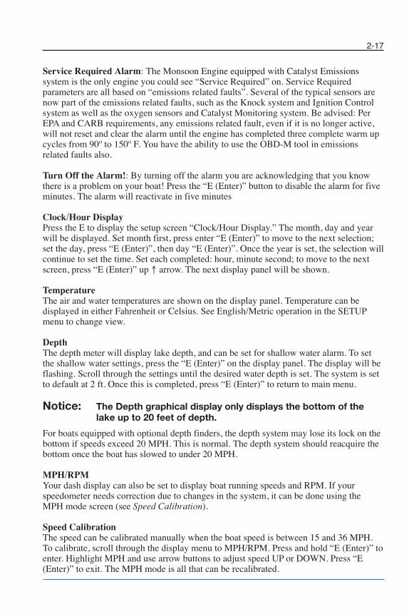
MaliView Cruise Speed Screen
Ballast Tank Levels and Fill Status
• Press “CRUISE” to enter cruise mode and to toggle between “SPEED” and “RPM”cruise modes.
• The up and down arrows will change the set-point in both “SPEED” and “RPM”cruise modes.
• Use the “ON/OFF/ENTER” button to turn the cruise on or off.• Press “MUTE” to mute the JBL radio. (This function only works with the JBL radio.)• Press “SAVE PRE-SET” to save or edit a pre-set. (See “Pre-Set” page.) This button
will also allow you to temporarily disable any alarm.
When the system has engaged, the throttle bar will turn green.
When the throttle is pushed past the ENGAGED gap, the system will give more speed aswell as turn red.
NOTES:• The gap appears when the engine has activated cruise and has control of the throttle.• The cruise must be turned on or off when the actual speed is below the set-point.• The cruise will only hold speed if the arrow is in the gap and is green.• The cruise can be turned off at any time but will not disengage until the throttle has
returned below the gap.
100%0%
SPEED OVER
100%0%
SPEED ENGAGED
12.0 17.0MPH ACTUALMPH SET
SPEED ON
100%0%SETUP
PRE-SETS
GAUGES
MEDIA ON / OFFENTER
STEREO 2 FM1 101.7
VOLTTEMP
OIL
11.8 V185 ºF65 PSI
E F
SA
VE
PR
E-S
ET
MUTE
F C L R MLSRIDER1000%
CURRENT
STOW
A STEP BEYOND
CRUISE
F C L R MLSRIDER1000%
CURRENT
STOW
A STEP BEYOND
Rider Picture
Wedge anglescreen
Indicates the wake shaping zone
Red indicates the filling status Green indicates the target level
Rider Name
Chapter 2_10: Chapter 2 doc.qxd 11/3/09 11:49 AM Page 20

2-21
MaliView RPM Cruise Screen
• Press “CRUISE” to enter cruise mode and to toggle between “SPEED” and “RPM”cruise modes.
• The up and down arrows will change the set-point in both “SPEED” and “RPM”cruise modes.
• Use the “ON/OFF/ENTER” button to turn the cruise on or off.• Press “MUTE” to mute the JBL radio. (This function only works with the JBL radio.)• Press “SAVE PRE-SET” to save or edit a pre-set. (See “Pre-Set” page.) This button
will also allow you to temporarily disable any alarm.
When the display prompts you with “RPM PULL UP,” the system will allow full throttlecontrol until a calculated speed has been reached.
After the calculated speed is reached, the system will automatically enter a “DECEL”mode and slowly return the engine throttle to the set RPM.
When the system has engaged, the throttle bar will turn green. Keep the arrow in the gapto allow the engine to hold the RPM.
NOTES:• The gap appears when the engine has activated cruise and has control of the throttle.• The RPM of the boat must be below the RPM set-point to turn on the cruise.• The cruise will only hold RPM if the arrow is in the gap and is green.• The cruise can be turned off at any time but will not disengage until the throttle has
returned below the gap.
100%0%
RPM ENGAGED
100%0%
RPM DECEL
100%0%
RPM PULL UP
SETUP
PRE-SETS
GAUGES
MEDIA ON / OFFENTER2500 750
RPM ACTUALRPM SETRPM ON
100%0%
STEREO 2 FM1 101.7
VOLTTEMP
OIL
11.8 V185 ºF65 PSI
E F
SA
VE
PR
E-S
ET
MUTE
F C L R MLSRIDER1000%
CURRENT
STOW
A STEP BEYOND
CRUISE
Chapter 2_10: Chapter 2 doc.qxd 11/3/09 11:49 AM Page 21

2-22
Ballast Monitoring System (BMS) (Standard on Wakesetter Model)
Figure 2-9. BMS
All Wakesetter models come standard with the Ballast Monitoring System (BMS)display. The BMS can be used to visually see the amount of water ballast that is in eachtank. The ballast amount is monitored in 1/4 tank increments, and can monitor the center,left and right rear tanks and optional front bow tank. The ballast fill switches are locatedon the dash switch panel labeled MLS. To activate the BMS, press the BALLAST buttonon the Dash Display. The BALLAST display window will show. To exit the BALLASTdisplay screen, press the Red button; this defaults to your Favorites Screen.
Boats that are not equipped with the ballast monitoring system will not have the ballastoption on the display. It will be replaced with the Speedo option. This is used as a short-cut to the speedometer calibration screen.
Power Wedge
Figure 2-10. Power Wedge
Chapter 2_10: Chapter 2 doc.qxd 11/3/09 11:49 AM Page 22

2-23
Figure 2-11. Power Wedge
The Power Wedge (PW) is an adjustable wake enlargement device designed specificallyfor wakeboarding. It is not intended to be used over 25 MPH. The PW alarm will activateif the foil is not in the “stowed” or “all the way up” position and the boat speed exceeds25 MPH. You must slow down to between 1 and 10 MPH to raise the foil all the way up.The Power Wedge is intended to be deployed “down” prior to pulling up the rider; it willnot deploy above 10 MPH.
Boats not equipped with PW must have the Power Wedge mode switched to N/A insteadof PRESENT.
The Power Wedge is a computer controlled intelligent device. The computer determinesif the boat speed is safe to operate the PW. If the boat speed and foil position are withinthe safe operational parameters, the computer will allow you to adjust the foil. If the boatspeed and foil position are out of the safe parameters, the Power Wedge will not operate.
The Power Wedge Foil will deploy from the fully up or “stowed” position to the fullydown or “operating position” as long as the boat speed is under 10 MPH. It will deploy“down” sitting on the trailer if the key is ON and the switch is depressed on the “DOWN”arrow. It will not deploy “up” unless the boat speed is between 1 and 10 MPH. Once thefoil is all the way down, you will have the ability to adjust the size and shape of yourwake when the boat speed is between 10 and 25 MPH. The driver should always beginthe towing session with the foil in the down position. Once the boat is at the desiredwakeboarding speed, the driver can increase the wake size by pressing the “UP” arrow onthe PW switch in momentary increments or decrease the wake size by pressing the“DOWN” arrow in momentary increments. The driver can monitor the Power Wedgegauge for reference to the adjustments. When the boat speed is between 10 and 25 MPH,the foil will not raise above the predetermined operating limit which is the largest,sharpest, usable wake in which the foil can create. With the foil in the lowest position, thewake is comparable to approximately 400 lb of ballast in the rear of the boat.
Your Malibu can be trailered or launched with the PW down, but make sure to raise itonce you are on the water. DO NOT operate the PW with people on the swim step or nearthe PW.
Chapter 2_10: Chapter 2 doc.qxd 11/3/09 11:49 AM Page 23
2-24
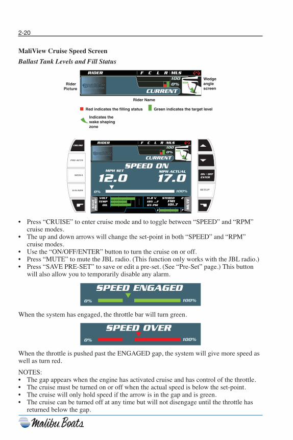
Notice: Be sure the wedge unit is up before loading boat on trailer.
Ensure all passengers are in the boat before changing wedgeposition. Stay clear of wedge unit while in motion. Fingersand clothing can be pinched between wedge arms andbracket, causing serious injury to passengers.
Figure 2-12. Power Wedge
Power Wedge Gauge CalibrationAfter the sensor has been properly installed/adjusted/mounted, the MMDC must beprogrammed to know where full “up” and “down” are. This adjustment is referred to as“Calibrating the Power Wedge.”
Other Reasons to Recalibrate: 1. Replacing the MMDC 2. Replacing/adjusting the Wedge Foil 3. Replacing the sensor
Due to the safety parameters on the Power Wedge that will not allow you to raise theWedge without the MMDC at a minimum of 1 MPH, you will find it easier to calibratethe Power Wedge on the water. Always do the final calibration on the water with theengine running so it will calibrate at the same voltage as when it is being used.
1. Start with the Wedge “All the way down.” 2. Turn the key to the ignition “ON” position. Using the center display controls, scroll
to the Service Screen and press “E.” Then scroll to Power Wedge and press “E,”then scroll to calibrate and press “E.”
Chapter 2_10: Chapter 2 doc.qxd 11/3/09 11:49 AM Page 24
2-25
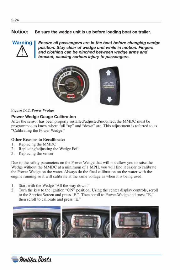
3. Make sure the Wedge is all the way down before you proceed. Make sure you have“DOWN” highlighted in the screen, press “E” once and DONE will change to CAL.Wait 2 seconds and press “E” again and CAL will change back to DONE. The downposition is now calibrated.
4. Now you will need to raise the Wedge “all the way up.” (MMDC must see 1 MPHbefore it will let the Wedge come up.) Once you are sure the Wedge is all the way up,scroll the curser over “UP.” With “UP” highlighted, press “E.” Wait 2 seconds andpress “E” again. The Power Wedge is now calibrated. Press the RED button severaltimes to get back to the main screen.
MaliView USB Update Screens
• Make sure one end of the USB cable is attached to the VIPER module.• Plug an approved USB memory stick into the other end of the USB cable.• Press “ENTER” to activate the “UPDATE” routine.• The system will reset automatically when complete.
Chapter 2_10: Chapter 2 doc.qxd 11/3/09 11:49 AM Page 25

2-26
Wedge Screen
• During the Wedge calibration, follow the screen instructions.• The “DOWN” values after calibration are typically 5-50 for the top number, and the
value for the bottom number is 0.• The “UP” values after calibration are typically 400-500 for the top number and 200
for the bottom number.
• “WEDGE ENABLED” is toggled on when the Power Wedge is present.• “AUTO WEDGE ENABLED” is a feature that will automatically lower the wedge to
decrease drag when the boat is going 75% below the speed set-point. The wedge willreturn to its desired angle when 85% of the desired cruise speed is met. This featurehelps with using less power to get on plane.
WEDGE SETUP SCREEN
READING a:\ViperApp.mem FROM THUMB DRIVE
VIPER BOOTLOADER Rev 1.0A
WEDGE SETUP SCREEN
PROGRAMING a:\ ViperApp.mem...
VIPER BOOTLOADER Rev 1.0A
Chapter 2_10: Chapter 2 doc.qxd 11/3/09 11:49 AM Page 26

2-27
Circuit Breakers
All major boat circuits are protected from shorting and overload by resettable circuitbreakers. If a problem develops with one of the following circuits, switch off the circuitand wait about one minute. Then push the appropriate breaker button fully and switch onthe circuit. If the circuit continues to trip, there is a problem somewhere in the system.See your dealership immediately to locate the problem.
Figure 2-13. Circuit Breaker Panels
Switches & Indicators
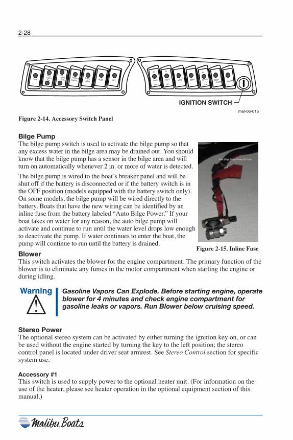
Accessory Switch PanelsThese panels are located in the dash directly below the standard gauges and are used toactivate the following features. You will find the feature or accessory provided withineach button face for description.
• Horn • Accessory Heater• Navigation Lights • Accessory Malibu Launch System (MLS)• Interior Lights • Accessory Stereo• Accessory Docking Lights • Bilge Pump• Accessory Tower Lights • Blower• Accessory Shower
Chapter 2_10: Chapter 2 doc.qxd 11/3/09 11:49 AM Page 27
2-28
Figure 2-14. Accessory Switch Panel
Bilge PumpThe bilge pump switch is used to activate the bilge pump so thatany excess water in the bilge area may be drained out. You shouldknow that the bilge pump has a sensor in the bilge area and willturn on automatically whenever 2 in. or more of water is detected.
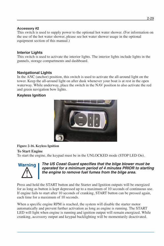
The bilge pump is wired to the boat’s breaker panel and will beshut off if the battery is disconnected or if the battery switch is inthe OFF position (models equipped with the battery switch only).On some models, the bilge pump will be wired directly to thebattery. Boats that have the new wiring can be identified by aninline fuse from the battery labeled “Auto Bilge Power.” If yourboat takes on water for any reason, the auto bilge pump willactivate and continue to run until the water level drops low enoughto deactivate the pump. If water continues to enter the boat, thepump will continue to run until the battery is drained.
BlowerThis switch activates the blower for the engine compartment. The primary function of theblower is to eliminate any fumes in the motor compartment when starting the engine orduring idling.
Gasoline Vapors Can Explode. Before starting engine, operateblower for 4 minutes and check engine compartment forgasoline leaks or vapors. Run Blower below cruising speed.
Stereo PowerThe optional stereo system can be activated by either turning the ignition key on, or canbe used without the engine started by turning the key to the left position; the stereocontrol panel is located under driver seat armrest. See Stereo Control section for specificsystem use.
Accessory #1This switch is used to supply power to the optional heater unit. (For information on theuse of the heater, please see heater operation in the optional equipment section of thismanual.)
Horn ACC Tower Lights
Docking Lights
Int Lights Dash
Nav Lights Anc ACC ACC
BlowerBilge
Pump Stero
hi
heater
low
fill
MLS
drn
fill
MLS
drn
IGNITION SWITCHmal-06-015
Figure 2-15. Inline Fuse
Chapter 2_10: Chapter 2 doc.qxd 11/12/09 4:17 PM Page 28
2-29
Accessory #2This switch is used to supply power to the optional hot water shower. (For information onthe use of the hot water shower, please see hot water shower usage in the optionalequipment section of this manual.)
Interior LightsThis switch is used to activate the interior lights. The interior lights include lights in thegunnels, storage compartments and dashboard.
Navigational LightsIn the ANC (anchor) position, this switch is used to activate the all-around light on thetower. Keep the all-around light on after dusk whenever your boat is at rest in the openwaterway. While underway, place the switch in the NAV position to also activate the redand green navigation bow lights.
Keyless Ignition
Figure 2-16. Keyless Ignition
To Start EngineTo start the engine, the keypad must be in the UNLOCKED mode (STOP LED On).
The US Coast Guard specifies that the bilge blower must beoperated for a minimum period of 4 minutes PRIOR to startingthe engine to remove fuel fumes from the bilge area.
Press and hold the START button and the Starter and Ignition outputs will be energizedfor as long as button is kept depressed up to a maximum of 10 seconds of continuous use.If engine fails to start after 10 seconds of cranking, START button can be pressed again,each time for a maximum of 10 seconds.
When a specific engine RPM is reached, the system will disable the starter motorautomatically and prevent further activation as long as engine is running. The STARTLED will light when engine is running and ignition output will remain energized. Whilecranking, accessory output and keypad backlighting will be momentarily deactivated.
Chapter 2_10: Chapter 2 doc.qxd 11/3/09 11:49 AM Page 29

2-30
To Stop EngineWith the engine running, press STOP button once. The START LED will go off andSTOP LED will go on to confirm engine is no longer running. System will go back toSTAND-BY mode. Press START to re-start engine or press STOP once again to turn offall outputs and LOCK system.
Blower Reminder / Auto-Blower FeatureSTART LED will flash when bilge blower should be operated – before cranking engine,for extended idling periods, when engine is stopped or stalls, etc. Operator should havethe bilge blower running during that time and should avoid attempting to start engineunless in emergency situations. Connecting the bilge blower to a Megalink DC Switchingsystem or optional CANbus driver module will perform this task automatically withoutuser input.
ACCESSORY ModeTo UNLOCK the system, enter the 4 to 8 digit ACCESSORY code followed by theSTART button to validate code. If code is valid, STOP LED will illuminate to confirmsystem is UNLOCKED. If code is invalid, START and STOP LED will blink 3 times. Re-enter code followed by START.
Once UNLOCKED, STOP LED will illuminate to indicate operation of theACCESSORY mode, ACCESSORY output will be turned on and electrical devicesconnected to this output can now be used. In the ACCESSORY mode, Ignition andStarter outputs are disabled.
Pressing the STOP key will turn off Accessory output and system will revert to itsLOCKED state.
Battery protection feature: In the event system is left in ACCESSORY mode forextended period of time, system will turn off all outputs if battery voltage falls below11.9V. STOP LED will flash slowly and backlight will turn off. From this state, pressingSTART will resume ACCESSORY mode, pressing STOP will LOCK system.
Configuration
DEALER CodeKeyless ignition comes with a pre-programmed DEALER code that is used to overridethe USER code and ACCESSORY code in the event user forgets his codes. DEALERcode cannot be changed.
Programming a USER CodeDefault USER code is “1234”. Use the following procedure to modify the code from aLOCKED state:
Step 1: Enter the current USER code or DEALER code and press the “1” and “4” buttonssimultaneously. The STOP LED will blink if entered code is valid. If code is invalid,START and STOP LED will blink alternately 3 times and start over again from step 1.
Step 2: Enter the new 4 to 8 digit USER code then press START. START and STOP LEDwill light for 1 second followed by a blinking STOP LED to indicate code needs to bevalidated by reentering the same code again.
Chapter 2_10: Chapter 2 doc.qxd 11/3/09 11:49 AM Page 30

2-31
Notice: USER code must be different from the ACCESSORY code.
Step 3: Enter again the new code then press START. If system recorded twice the samevalid code, STOP LED will light steady and Keyless Ignition will be in STAND-BYmode. If codes are not valid, START and STOP LED will blink alternately 3 times. Startover again from step 1.
Programming an ACCESSORY CodeDefault ACCESSORY code is “1111”. Use the following procedure to modify this codefrom a LOCKED state:
Step 1. Enter the DEALER code or USER code and press the “2” and “3” buttonssimultaneously.The START LED will blink if entered code is valid. If code is invalid, START and STOPLED will blink alternately 3 times and start over again from step 1.
Step 2: Enter the new 4 to 8 digit ACCESSORY code then press START. START andSTOP LED will light for 1 second followed by a blinking START LED to indicate codeneeds to be validated by re-entering the same code again.
Notice: ACCESSORY code must be different from the USER code.
Step 3: Enter again the new code then press START. If system recorded twice the samevalid code, STOP LED will light steady and Keyless Ignition will be in ACCESSORYmode. If codes are not valid, START and STOP LED will blink alternately 3 times. Startover again from step 1.
Backlight Intensity AdjustmentBacklighting intensity of the keypad can be adjusted to individual owner preference usingthe “2” and “4” buttons when system is in STAND-BY mode or engine is running. Pressthe “2” button to increase backlight intensity. Press the “4” button to decreasebacklighting intensity. Each step increases/decreases intensity by about 5%. Holding oneof the buttons depressed will automatically ramp up or down intensity until button isreleased. Backlight setting will be memorized in the system’s non-volatile memory.
MUX SwitchThe 2010 Malibu system comes with three different MUX switch modules: one on theleft that has the HORN button; one on the right that has the STEREO buttons; and anoptional one for the back that has the STEREO buttons.
These modules have the ability to have any function added, subtracted or moved. Thismakes the boat a lot more flexible when adding or deleting options from the switches.
The MUX switches are connected to the boat and POWER module by the CAN BUS. IfCAN communication is lost between it and the POWER module, the MUX will displaylast known output state.
The MUX switch indicates the current status of each switch, so that if the MINI activatesone of the ballast fill pumps, the MUX switch will show FILL on that tank.
Chapter 2_10: Chapter 2 doc.qxd 11/3/09 11:49 AM Page 31

2-32
The MUX is designed to stay active for 30 minutes after ignition is off and all switchesare off.
The MUX switch will wake up anytime a button is pressed with ignition off.
The Vertical button is called the PAGE button. It allows the user to toggle through themenu to buttons on other pages.
Figure 2-17. MUX Switch
Chapter 2_10: Chapter 2 doc.qxd 11/3/09 11:49 AM Page 32
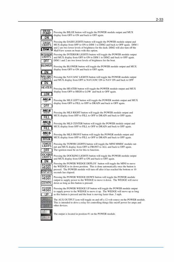
2-33
Pressing the BILGE button will toggle the POWER module output and MUXdisplay from OFF to ON and back to OFF again.
Pressing the BLOWER button will toggle the POWER module output and MUX display from OFF to ON and back to OFF again.
Pressing the DASH LIGHTS button will toggle the POWER module output and MUX display from OFF to ON to DIM 1 to DIM2 and back to OFF again. DIM 1 and 2 are two lower levels of brightness for the dash. DIM2 will also turn off the MaliView screen on boats with this option.
Pressing the INTERIOR LIGHTS button will toggle the POWER module output and MUX display from OFF to ON to DIM 1 to DIM2 and back to OFF again. DIM 1 and 2 are two lower levels of brightness for the boat.
Pressing the NAV/ANC LIGHTS button will toggle the POWER module output and MUX display from OFF to NAV/ANC ON to NAV ON and back to OFF
Pressing the HEATER button will toggle the POWER module output and MUX display from OFF to HIGH to LOW and back to OFF again.
Pressing the MLS LEFT button will toggle the POWER module output and MUX display from OFF to FILL to OFF to DRAIN and back to OFF again.
Pressing the MLS RIGHT button will toggle the POWER module output and MUX display from OFF to FILL to OFF to DRAIN and back to OFF again.
Pressing the MLS CENTER button will toggle the POWER module output and MUX display from OFF to FILL to OFF to DRAIN and back to OFF again.
Pressing the MLS FRONT button will toggle the POWER module output and MUX display from OFF to FILL to OFF to DRAIN and back to OFF again.
Pressing the TOWER LIGHTS button will toggle the MINI MMDC module out-put and MUX display from OFF to FRONT to ALL and baThe ignition must be on for this to function.
ck to OFF again.
Pressing the DOCKING LIGHTS button will toggle the POWER module output and MUX display from OFF to ON and back to OFF again.
Pressing the POWER WEDGE UP button will toggle the
The AUX OUTPUT icon will toggle on and off a 12-volt source on the POWER module.This is intended to drive a relay for controlling things like on/off power for amps and other devices.
The output is located in position #1 on the POWER module.
POWER module output to supply power to the WEDGE to move it up. The WEDGE will move up as long as this button is pressed and the boat is moving faster than .3 mph.
Pressing the POWER WEDGE DEPLOY button will toggle the MINI to move the WEDGE to its down position. This is done automatically once the button is pressed. The POWER module will turn off after it has reached the bottom or 10 seconds has elapsed.
Pressing the POWER WEDGE DOWN button will toggle the POWER module output to supply power to the WEDGE to move it down. The WEDGE will move down as long as this button is pressed.
Chapter 2_10: Chapter 2 doc.qxd 11/4/09 4:09 PM Page 33
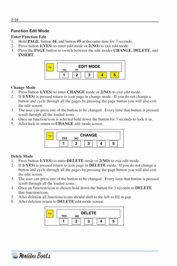
2-34
Function Edit ModeEnter Function Edit1. Hold PAGE, button #4, and button #5 at the same time for 3 seconds.2. Press button 1(YES) to enter edit mode or 2(NO) to exit edit mode.3. Press the PAGE button to switch between the edit modes CHANGE, DELETE, and
INSERT.
Change Mode1. Press button 1(YES) to enter CHANGE mode or 2(NO) to exit edit mode.2. If 1(YES) is pressed return to icon page in change mode. If you do not change a
button and cycle through all the pages by pressing the page button you will also exitthe edit screen.
3. The user can press one of the button to be changed. Every time that button is pressedscroll through all the loaded icons.
4. Once an function/icon is selected hold down the button for 3 seconds to lock it in.5. After lock in return to CHANGE edit mode screen.
Delete Mode1. Press button 1(YES) to enter DELETE mode or 2(NO) to exit edit mode.2. If 1(YES) is pressed return to icon page in DELETE mode. If you do not change a
button and cycle through all the pages by pressing the page button you will also exitthe edit screen.
3. The user can press one of the button to be changed. Every time that button is pressedscroll through all the loaded icons.
4. Once an function/icon is chosen hold down the button for 3 seconds to DELETEthat function/icon.
5. After deletion all functions/icons should shift to the left to fill in gap.6. After deletion return to DELETE edit mode screen.
Page DELETE
54321YES NO
Page CHANGE
54321YES NO
Page EDIT MODE
54321YES NO
Chapter 2_10: Chapter 2 doc.qxd 11/3/09 11:49 AM Page 34

2-35
Insert Mode1. Press button 1(YES) to enter INSERT mode or 2(NO) to exit edit mode.2. If 1(YES) is pressed return to icon page in INSERT mode. If you do not change a
button and cycle through all the pages by pressing the page button you will also exitthe edit screen.
3. The user can press one of the button to be changed. Every time that button is pressedthe mux switch will show a different icon.
4. Once an function/icon is chosen hold down the button for 3 seconds to INSERT thatfunction/icon.
5. After insertion all functions/icons should shift to the right.6. After insertion return to INSERT edit mode screen.
Factory Default Mode1. Press the PAGE button and Button #1 and #2 for 3 seconds to enter RETURN TO
FACTORY DEFAULT mode.2. If 1(YES) is selected the all the functions and icon locations will return to factory
settings.3. If 2(NO) is selected the switch module will return to normal operations with no
changes.
Page Return to Factory Default?
54321
YES NO
Page INSERT
54321YES NO
Chapter 2_10: Chapter 2 doc.qxd 11/3/09 11:49 AM Page 35

2-36
Throttle Control
The throttle lever is located to the right of the driver. When the throttle is vertical, it is in the “NEUTRAL”position. At the base of the throttle you will find the shiftlock knob. Pulling outward on this knob disengages thetransmission, thereby allowing use of the throttle withoutengaging the transmission. This is used for warm-up of theengine in neutral. Be sure to position the throttle vertically(in “NEUTRAL”), before re-engaging the transmission, bydepressing the knob.
When engaging the transmission from “NEUTRAL” to either forward or reverse, you must pull up on the safety collar located directly below thethrottle lever knob.
Do not shift from forward to reverse at high RPMs; damage tothe transmission will result. When shifting from forward toreverse you must stop in the NEUTRAL position, doing thisallows the engine to run in its idle position before moving intothe opposite gear. Moving the shift lever from FORWARD toREVERSE without stopping in NEUTRAL can cause thetransmission to “slam” into gear, damaging the transmissionand/or causing the engine to shut off. This will causetemporary loss of boat control which can cause damageand/or injury to the boat and/or persons in/or around theboat.
Before starting the engine or engaging transmission, ensureall swimmers are out of the water.
Electronic Throttle Control (ETC)All 2006-2010 Malibu Boats are equipped with electronic throttle control AKA “Drive-By-Wire.” The throttle cable has been removed and several components on the engine and helmthrottle control have been changed. The helm throttle control “E-MV3” is now dual, variablevoltage potentiometer that sends electronic signals back to the engine ECM via a shieldedwire harness with the highest quality GM/Delphi water-tight connectors that mates to theengine ECM. The ECM then uses the signals from the E-MV3 to precisely control theengine speed with an electronic throttle body. Do not make any modifications to the throttlecontrol to ensure proper operation.
Figure 2-18. Throttle
Chapter 2_10: Chapter 2 doc.qxd 11/3/09 11:49 AM Page 36
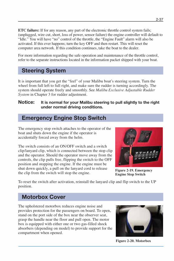
2-37
ETC failure: If for any reason, any part of the electronic throttle control system fails;(unplugged, wire cut, short, loss of power, sensor failure) the engine controller will default to“Idle.” You will have “no” control of the throttle, the “Engine Fault” alarm will also beactivated. If this ever happens; turn the key OFF and then restart. This will reset thecomputer area network. If this condition continues, take the boat to the dealer.
For more information regarding the safe operation and maintenance of the throttle control,refer to the separate instructions located in the information packet shipped with your boat.
Steering System
It is important that you get the “feel” of your Malibu boat’s steering system. Turn thewheel from full left to full right, and make sure the rudder is turning accordingly. Thesystem should operate freely and smoothly. See Malibu Exclusive Adjustable RudderSystem in Chapter 3 for rudder adjustment.
Notice: It is normal for your Malibu steering to pull slightly to the rightunder normal driving conditions.
Emergency Engine Stop Switch
The emergency stop switch attaches to the operator of the boat and shuts down the engine if the operator isaccidentally forced away from the helm.
The switch consists of an ON/OFF switch and a switchclip/lanyard clip, which is connected between the stop clipand the operator. Should the operator move away from thecontrols, the clip pulls free, flipping the switch to the OFFposition and stopping the engine. If the engine must be shut down quickly, a pull on the lanyard cord to release the clip from the switch will stop the engine.
To reset the switch after activation, reinstall the lanyard clip and flip switch to the UPposition.
Motorbox Cover
The upholstered motorbox reduces engine noise andprovides protection for the passengers on board. To open,stand on the port side of the box near the observer seat,grasp the handle near the floor and pull open. The motorbox is equipped with either one or two gas-filled shockabsorbers (depending on model) to provide support for thecompartment when opened.
Figure 2-19. EmergencyEngine Stop Switch
Figure 2-20. Motorbox
Chapter 2_10: Chapter 2 doc.qxd 11/4/09 4:08 PM Page 37
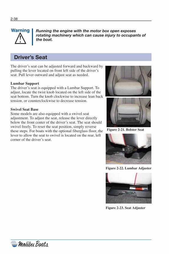
2-38
Running the engine with the motor box open exposesrotating machinery which can cause injury to occupants ofthe boat.
Driver’s Seat
The driver’s seat can be adjusted forward and backward bypulling the lever located on front left side of the driver’sseat. Pull lever outward and adjust seat as needed.
Lumbar SupportThe driver’s seat is equipped with a Lumbar Support. Toadjust, locate the twist knob located on the left side of theseat bottom. Turn the knob clockwise to increase lean backtension, or counterclockwise to decrease tension.
Swivel Seat BaseSome models are also equipped with a swivel seatadjustment. To adjust the seat, release the lever directlybelow the front center of the driver’s seat. The seat shouldswivel freely. To reset the seat position, simply reversethese steps. For boats with the optional fiberglass floor, thelever to allow the seat to swivel is located on the rear, leftcorner of the driver’s seat.
Figure 2-21. Bolster Seat
Figure 2-22. Lumbar Adjuster
Figure 2-23. Seat Adjuster
Chapter 2_10: Chapter 2 doc.qxd 11/4/09 1:13 PM Page 38
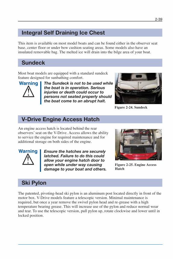
2-39
Integral Self Draining Ice Chest
This item is available on most model boats and can be found either in the observer seatbase, center floor or under bow cushion seating areas. Some models also have aninsulated removable bag. The melted ice will drain into the bilge area of your boat.
Sundeck
Most boat models are equipped with a standard sundeckfeature designed for sunbathing comfort.
The Sundeck is not to be used whilethe boat is in operation. Seriousinjuries or death could occur topersons not seated properly should the boat come to an abrupt halt.
Figure 2-24. Sundeck
V-Drive Engine Access Hatch
An engine access hatch is located behind the rearobservers’ seat on the V-Drive. Access allows the ability to service the engine for required maintenance and foradditional storage on both sides of the engine.
Ensure the hatches are securely latched. Failure to do this couldallow your engine hatch door toopen while under way causingdamage to your boat and others.
Ski Pylon
The patented, pivoting-head ski pylon is an aluminum post located directly in front of themotor box. V-Drive models feature a telescopic version. Minimal maintenance isrequired, but once a year remove the swivel pylon head and re-grease with a hightemperature bearing grease. This will increase use of the pylon and reduce normal wearand tear. To use the telescopic version, pull pylon up, rotate clockwise and lower until inlocked position.
Figure 2-25. Engine AccessHatch
Chapter 2_10: Chapter 2 doc.qxd 11/4/09 1:13 PM Page 39

2-40
Malibu Boats’ “Pivoting-Head” ski pylon isdesigned for normal water skiing activities:slalom, jumping, kneeboarding, tricks, andbarefooting. Any other uses such asparasailing, kite flying, towing pyramids ofskiers, etc., may over-stress the pylon andpossibly cause personal injury and/orequipment damage. DO NOT overload thepylon or use it for anything other thanwatersports.
Swim Platform
A removable swim step is located on the stern of the boat to provide easy access into andout of the water for boat skiers and swimmers. To remove, rotate the latches away fromthe transom and align the pin with the notches to pull it out. Depending on model, eitherlift or slide back on the platform. To replace, reverse these steps. Be sure the latches aresecurely fastened.
DO NOT use the boarding platform for any other purpose than boardingthe boat or preparation of enteringthe water, and DO NOT use theboarding platform when the engine is running.
A spinning propeller or carbonmonoxide can cause serious injury or death. Stay off and keep away from boarding platform while engine is running. The boardingplatform must be attached when the boat is in use.
To access the optional swim step ladder, lift up on the handle of the rubber strap to unhook it then pull it down and pull the ladder out. To replace, reverse these steps.Make sure the swim step locks are fully locked beforelaunching the boat.
Figure 2-26.Pivoting-HeadSki Pylon
Figure 2-27. Swim Platform
Figure 2-28. Swim Step PinRemoval
Figure 2-29. Swim StepLadder Strap
Chapter 2_10: Chapter 2 doc.qxd 11/3/09 11:49 AM Page 40

2-41
Navigational Lights
As required by the U.S. Coast Guard and most maritimeauthorities, all recreational vessels are required to displaynavigational lights between sunset and sunrise and otherperiods of reduced visibility. All Malibu Boats are equippedwith bow and all-around navigational lights.
The bow light located at the tip of the bow is two colored —red and green, and is used to keep others aware of your presence when operating your boat at night.
A covered, two-pronged connector can be found on the top of the transom on boatswithout a tower. The all-around light is plugged into this connector when needed andstored under the rear passenger seat when not in use. Boats equipped with towers have anall-around light fitted to the top of the tower.
Storage Areas
Bow Storage AreaAccess to a large storage area located in the bow of all models is accessible by lifting thebottom-lifting strap of the observers’ seat back. The size of the storage differs betweenopen and closed bow versions. On open bow boats the seat cushions can be removed toprovide additional storage.
Gunnel Ski StorageConveniently located on both sides of the boat, these storage areas are ideal for thestorage of water skis, and other items.
Floor Ski StorageLocated on the floor between the driver’s and observers’ seats on open bow models withwalk-through, is a panel that when lifted provides access to a large area that can be usedprimarily for storage of water skis.
Transom StorageSome boat models are equipped with transom skistorage. Depending on the model, the storage isaccessible from either the interior by lifting theobservers’ seat or from the transom swim platformby lifting the hatch cover. Most models are equippedwith a locking device for the secure storage of yourski items.
Figure 2-30. Bow Light
Figure 2-31. Lockable TransomStorage
Chapter 2_10: Chapter 2 doc.qxd 11/3/09 11:49 AM Page 41
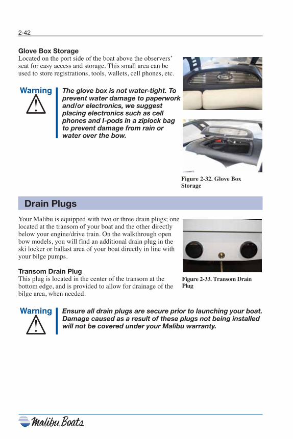
2-42
Glove Box StorageLocated on the port side of the boat above the observers’ seat for easy access and storage. This small area can beused to store registrations, tools, wallets, cell phones, etc.
The glove box is not water-tight. Toprevent water damage to paperworkand/or electronics, we suggestplacing electronics such as cellphones and I-pods in a ziplock bag to prevent damage from rain orwater over the bow.
Drain Plugs
Your Malibu is equipped with two or three drain plugs; onelocated at the transom of your boat and the other directlybelow your engine/drive train. On the walkthrough openbow models, you will find an additional drain plug in theski locker or ballast area of your boat directly in line with your bilge pumps.
Transom Drain Plug This plug is located in the center of the transom at thebottom edge, and is provided to allow for drainage of thebilge area, when needed.
Ensure all drain plugs are secure prior to launching your boat.Damage caused as a result of these plugs not being installedwill not be covered under your Malibu warranty.
Figure 2-32. Glove BoxStorage
Figure 2-33. Transom DrainPlug
Chapter 2_10: Chapter 2 doc.qxd 11/3/09 11:49 AM Page 42

2-43
Bilge Drain Plug(s)A T-handled, brass bilge drain plug is located in the engine compartment of all models. Location is normallydirectly below the drive-train unit. To access, lift motor box and look aft of the ski-tow pylon, and forward of theengine. On the V-drive models, the T-handle can be foundby lifting the rear passenger seat. The T-handle is locatedjust below the V-drive unit.
Figure 2-34. Bilge Drain Plug
Ensure that all transom and bilge drain plugs are securely inplace before placing the boat in the water.
Speedometer Pickup
Your boat is equipped with a Paddle wheel speedometerpickup, which can be found directly under the runningsurface of your boat. The paddle wheel is used to measurestatic water by rotation of the paddle wheel unit. Thisinformation is transferred to the dash computer and acomputer program converts information which istransferred to the speedometer gauge.
See Troubleshooting section of this manual for basicmaintenance information.
Tilt Steering Wheel
The tilt steering wheel allows for maximum driver comfort. To adjust the height of the wheel, simply pressdown on the lever located under the wheel. Move the wheel to the position that is most comfortable. When thewheel is in the desired position, simply release the lever tolock the wheel in place.
Figure 2-35. Thru-HullPaddle Wheel Pickup
Figure 2-36. Tilt Steering
Chapter 2_10: Chapter 2 doc.qxd 11/3/09 11:49 AM Page 43
2-44
ExhaustThe exhaust system is used to remove engine exhaust fumes. To ensure that your boat’sexhaust system is working correctly, it is important that you inspect for exhaust leaks.The following information will allow you to check these systems. Keep in mind that youwill be checking engine while turned on, and that you will need to take safeguards againstgetting yourself or others caught in the moving parts. Use extreme caution whileperforming this task.
• Turn engine off and disconnect the engine safety switch. Be sure the throttleshift control is neutral. The engine must be cool.
• Open the engine and visually check the exhaust system from the engine to thetransom for obvious damage.
• Reinstall engine safety switch and start the engine with engine compartment open.Check hose connections between the exhaust manifolds and the muffler for leakage.
• If leakage is apparent, tighten the hose clamps, being careful not to crimp the hose.See your Malibu dealer for parts and or service.
Notice : The 2010 Monsoon and LS3 engines equipped with the ETXCatalyst Exhaust Manifolds may produce an unusual smellwhich is characteristic of an engine with a catalyst exhaustsystem.
Chapter 2_10: Chapter 2 doc.qxd 11/3/09 11:49 AM Page 44
2-45
VentilationThe ventilation is used to remove potentially hazardous accumulation of explosive vaporsfrom the bilge areas of your boat’s hull and engine compartment. Therefore, properventilation is essential to the safety of the boat and persons in or around the boat structure.
Your boat is equipped with a ventilation system that will ensure complete removal of thesedangerous fumes. However, it is your responsibility as the operator of the boat to ensurethese systems are working efficiently. The boat’s primary source for expelling fumes fromthe boat is the blowers located in the bottom of the bilge and at the transom venting points.
Your boat is also equipped with a natural air-intake that forces air through a venting systemon the deck of your boat, and channels air from the bilge to the transom vent.
CoolingMost boats will be cooled with a continuous intake of lake water circulating it aroundengine components.
Closed Cooling SystemIf your boat is equipped with an optional closed cooling system, you will need to maintaincorrect fluid levels.
• Open engine compartment and remove reservoir cap.• Ensure coolant is to the top of the reservoir filler neck.• Use Sierra Anti-Freeze.
Notice: To ensure we are always mindful of our environment; it is anIndmar and Malibu Boat recommendation to use Sierra Brandantifreeze because of its propylene glycol formulation. SIERRAAntifreeze is less toxic and safer than ethylene glycol coolantsto children, pets and wildlife, in case of spills, leaks, boil-overor careless disposal.
The engine must be cool when checking the coolant level.Hot coolant and steam under pressure may cause injury.
Chapter 2_10: Chapter 2 doc.qxd 11/3/09 11:49 AM Page 45

2-46
Optional Equipment
HeaterIf your boat is equipped with a heater, you will find anON/OFF accessory switch located on the dash panel. Locatedat the base of the observer seat walkway is a snorkel tube thatcan be pulled out and directed wherever you like within a five-foot radius. Please refer to the information provided inyour owner’s packet for specific use.
Figure 2-37. Heater
Boat CoverIf your boat is equipped with this option, know the type of cover you are placing on your boat. SomeBoat Covers have been made strictly for mooringand storage only, and some have been made forstorage and travel. If you question the type of coverthat you have purchased, check with your Malibudealer for assistance. Do not cover the boat if theinterior is wet or damp. This can promote mildewgrowth.
Figure 2-38. Boat Cover
Damage caused to your boat as a result of improper coveruse is not covered under your Malibu Boats warranty.Damage can result from wind whipping, and possibly causeabrasions to your gelcoat surface or upholstery. Use theproper shipping cover for travel purposes.
StereoThe stereo head unit is located in the starboard side walk-throughpanel (in the shifter panel above the shifter in Ride models). Toturn the stereo on, the dash ignition key switch must be turned on.The key can be turned to the left if you will not be running theboat. Some systems, if equipped, will have an optional remote padlocated at the back of the boat either in the passenger area, orexterior transom. For specific stereo use, please refer to the stereomanual that was included in your owner’s packet. Standard on allboats equipped with stereo system is an MP3 input line. Seeinstructions found in your owner’s packet for specific use.
If your boat was equipped with optional sound equipment toinclude CD changer, amplifier or subwoofer, please refer to thesespecific manuals included in the owners’ packet for use.
Figure 2-39. Stereo
Figure 2-40. Stereo Remote
Chapter 2_10: Chapter 2 doc.qxd 11/3/09 11:49 AM Page 46
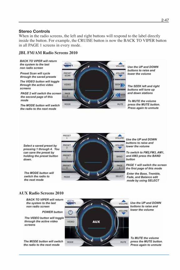
2-47
Stereo ControlsWhen in the radio screens, the left and right buttons will respond to the label directlyinside the button. For example, the CRUISE button is now the BACK TO VIPER buttonin all PAGE 1 screens in every mode.
JBL FM/AM Radio Screens 2010
AUX Radio Screens 2010
Chapter 2_10: Chapter 2 doc.qxd 11/3/09 11:49 AM Page 47
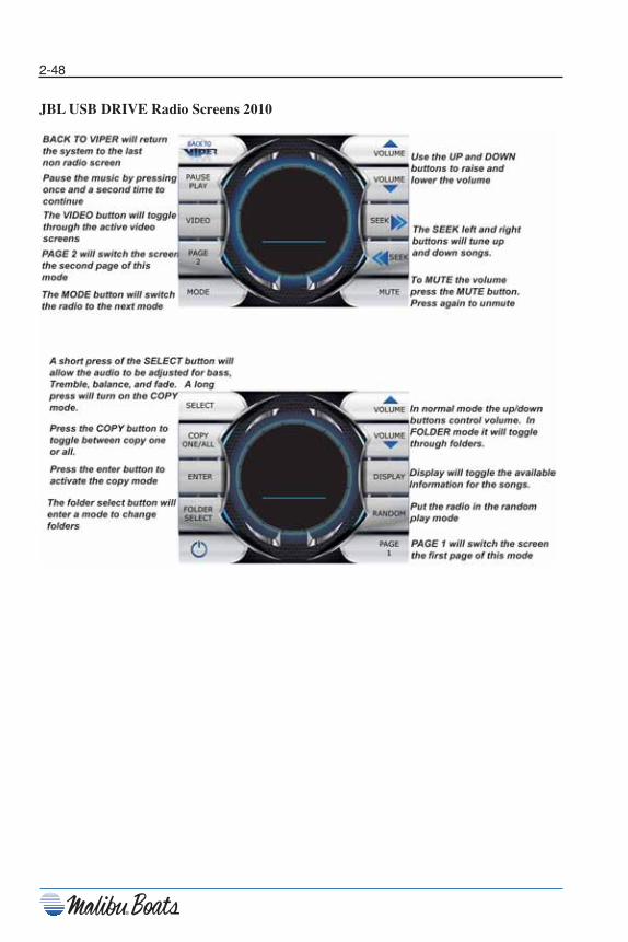
2-48
JBL USB DRIVE Radio Screens 2010
Chapter 2_10: Chapter 2 doc.qxd 11/3/09 11:49 AM Page 48
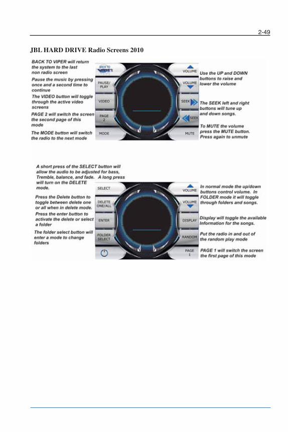
2-49
JBL HARD DRIVE Radio Screens 2010
Chapter 2_10: Chapter 2 doc.qxd 11/3/09 11:49 AM Page 49

2-50
SIRIUS Radio Screens 2010
Chapter 2_10: Chapter 2 doc.qxd 11/3/09 11:49 AM Page 50
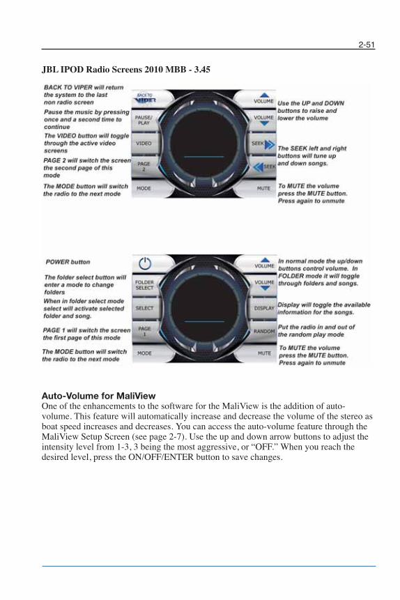
2-51
JBL IPOD Radio Screens 2010 MBB - 3.45
Auto-Volume for MaliViewOne of the enhancements to the software for the MaliView is the addition of auto-volume. This feature will automatically increase and decrease the volume of the stereo asboat speed increases and decreases. You can access the auto-volume feature through theMaliView Setup Screen (see page 2-7). Use the up and down arrow buttons to adjust theintensity level from 1-3, 3 being the most aggressive, or “OFF.” When you reach thedesired level, press the ON/OFF/ENTER button to save changes.
Chapter 2_10: Chapter 2 doc.qxd 11/3/09 11:49 AM Page 51
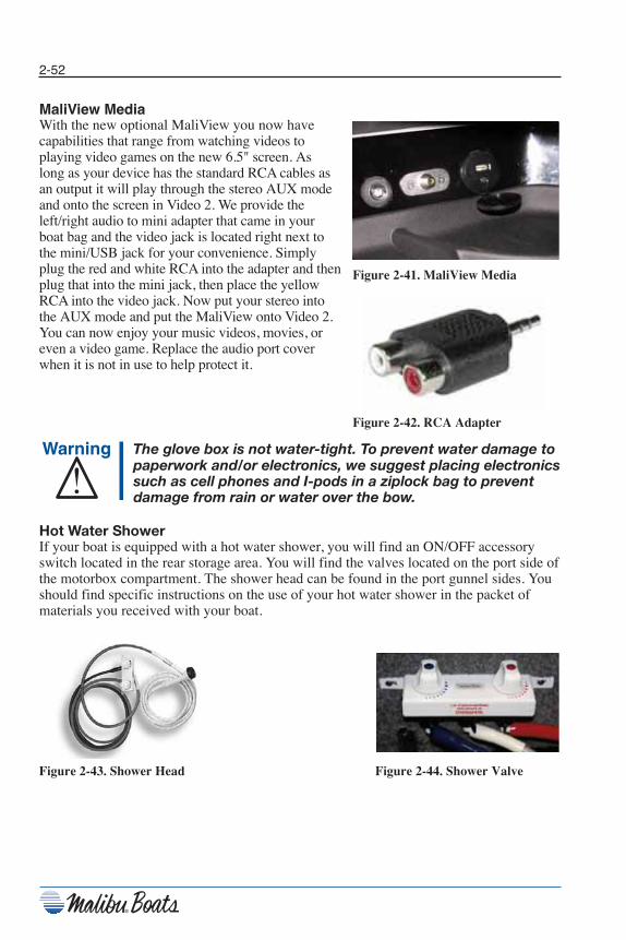
2-52
MaliView MediaWith the new optional MaliView you now have capabilities that range from watching videos toplaying video games on the new 6.5" screen. Aslong as your device has the standard RCA cables asan output it will play through the stereo AUX modeand onto the screen in Video 2. We provide theleft/right audio to mini adapter that came in yourboat bag and the video jack is located right next tothe mini/USB jack for your convenience. Simplyplug the red and white RCA into the adapter and thenplug that into the mini jack, then place the yellowRCA into the video jack. Now put your stereo into the AUX mode and put the MaliView onto Video 2.You can now enjoy your music videos, movies, oreven a video game. Replace the audio port coverwhen it is not in use to help protect it.
The glove box is not water-tight. To prevent water damage topaperwork and/or electronics, we suggest placing electronicssuch as cell phones and I-pods in a ziplock bag to preventdamage from rain or water over the bow.
Hot Water ShowerIf your boat is equipped with a hot water shower, you will find an ON/OFF accessoryswitch located in the rear storage area. You will find the valves located on the port side ofthe motorbox compartment. The shower head can be found in the port gunnel sides. Youshould find specific instructions on the use of your hot water shower in the packet ofmaterials you received with your boat.
Figure 2-43. Shower Head Figure 2-44. Shower Valve
Figure 2-41. MaliView Media
Figure 2-42. RCA Adapter
Chapter 2_10: Chapter 2 doc.qxd 11/3/09 11:49 AM Page 52

2-53
Pull-Up CleatsPull-Up cleats are available for all boat models. Thesecleats will sit flush on the side of the boat deck whendepressed. To use the cleats, simply pull them up. Push thecleats down to stow them.
Docking LightsThe docking lights should only be used during slow speed docking maneuvers. The lights are activated by a switch on the accessory switch panel and have a 10 amp circuit breaker. The dockinglights use LED bulbs which cannot be replaced.
TowerIllusion XThe Malibu Illusion X is equipped with a built-in navigationlight and a Quick Pin Release System. The Illusion X isstandard on both Ride Series models.
Illusion G3The Illusion G3 has a solid foundation of billet aluminum bases and billet tower support wings backing the 3"stainless steel hoop. The Illusion G3 features dual gasspring shocks to assist in creating the feature of weightlessfold-down. It uses two bolts under the top frame rail of thetower base to fasten the tower in the UP position. Theseneed to be periodically checked for tightness. The IllusionG3 is standard on Wakesetters and optional on Sunscapesand the Response FXi.
Due to vibration and rough waterconditions it is possible for bolts toloosen. It is recommended to periodically inspect allmounting bolts as part of maintenance: (Tower, WakeboardRacks, Lights, Speakers, etc.) to ensure they are tight. Seeyour local dealer for any questions and/or assistance. Failureto do so can cause serious damage and/or injury to the boatand/or passengers.
Properly stow the bimini top in its boot and remove all boards from the board racks prior to towing/trailering yourboat. Speeds exceeding 50 MPH (80 km/h) with the bimininot properly stowed may cause damage to the bimini top.Damage to the bimini from towing while not stowed is notcovered under warranty. Damaged or excessive wear toboard racks caused by towing or trailering with boardsattached is not covered under warranty.
Figure 2-45. Pull-Up Cleat
Figure 2-46. Illusion X
Figure 2-47. Illusion G3
Figure 2-48. Proper Stowageof Bimini
Chapter 2_10: Chapter 2 doc.qxd 11/12/09 4:18 PM Page 53
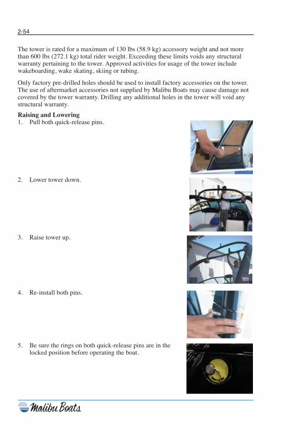
2-54
The tower is rated for a maximum of 130 lbs (58.9 kg) accessory weight and not morethan 600 lbs (272.1 kg) total rider weight. Exceeding these limits voids any structuralwarranty pertaining to the tower. Approved activities for usage of the tower includewakeboarding, wake skating, skiing or tubing.
Only factory pre-drilled holes should be used to install factory accessories on the tower.The use of aftermarket accessories not supplied by Malibu Boats may cause damage notcovered by the tower warranty. Drilling any additional holes in the tower will void anystructural warranty.
Raising and Lowering1. Pull both quick-release pins.
2. Lower tower down.
3. Raise tower up.
4. Re-install both pins.
5. Be sure the rings on both quick-release pins are in the locked position before operating the boat.
Chapter 2_10: Chapter 2 doc.qxd 11/3/09 11:49 AM Page 54
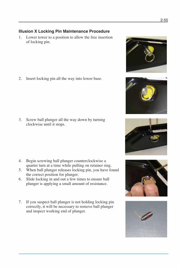
2-55
Illusion X Locking Pin Maintenance Procedure1. Lower tower to a position to allow the free insertion
of locking pin.
2. Insert locking pin all the way into lower base.
3. Screw ball plunger all the way down by turning clockwise until it stops.
4. Begin screwing ball plunger counterclockwise a quarter turn at a time while pulling on retainer ring.
5. When ball plunger releases locking pin, you have foundthe correct position for plunger.
6. Slide locking in and out a few times to ensure ballplunger is applying a small amount of resistance.
7. If you suspect ball plunger is not holding locking pin correctly, it will be necessary to remove ball plungerand inspect working end of plunger.
Chapter 2_10: Chapter 2 doc.qxd 11/3/09 11:49 AM Page 55
If, upon inspection of the ball plunger, you find it is notspringing back into place when pushed in, it will benecessary to replace it. The part number is 400-2218.
If ball plunger is not working properly, do not use boat withtower in the “UP” position until plunger has been replaced.
HardwareMost of the metal hardware on your boat consists of brass, stainless steel, or aluminumand should be cleaned on a periodic basis with soap and water. In fresh water, metalfittings and hardware should be sprayed regularly with a rust inhibitor and after every usein saltwater.
DO NOT use cleaners that are not intended for use on stainless steel. Glass, tile, counteror citrus cleaners can damage hardware permanently. Always follow cleaning, byapplying a high-quality metal polish or automotive wax after cleaning. Test products inan inconspicuous area before applying to the complete surface, especially if you are notfamiliar with the product.
All metal parts, including but not limited to tower accessories, board racks or speakercans, should be cleaned with mild soap and water frequently and waxed periodically. Acorrosion protectant is highly recommended on these components, especially for use inareas of or in proximity to salt/brackish water. Pitting, corrosion or oxidation is notcovered under warranty. Pitting is not the same as separation.
2-56
Chapter 2_10: Chapter 2 doc.qxd 11/12/09 4:19 PM Page 56

2-57
Wedge
The Malibu Manual Wedge foil is a solid, one piece,welded design constructed from solid stainless steel. Thewedge foil no longer locks in the down position. It isdesigned to move up or down freely and locate in the down position.
To lower wedge unit, depress spring loaded pins and lowerfoil. Be sure to raise and lock foil in the up position eachtime after use.
If your boat is equipped with the Wedge option, you willfind that the unit has two positions - DOWN or UP. Toadjust wedge position, access wedge through the swimplatform door.
Ensure both spring loaded pins are engaged before taking off.
Excessive speeds over 25 MPHcould cause adverse handlingconditions. It is recommended that you put the Wedge unit inthe UP position if you will be traveling over these speeds.
Scarpa Suppression Plate (SSP) The Scarpa Suppression plate is an optional add-on featureavailable for boats built with the Wedge boat bracket installed,used to enhance barefoot ski wake characteristics on Responsemodel ski boats. The plate is installed to an existing Wedge bracket.
Optional Malibu Launch System (MLS)The Malibu Launch System (MLS) ballast system allows water to be stored on board to increase hull weight for largerwakeboard wakes. Depending on model the MLS can beavailable as front, center or rear ballast tanks. If your boat is equipped with this feature,locate the MLS switches on the dash accessory panel to fill or drain the ballast tanks;press switch up to fill, or down to drain.
Figure 2-51. ScarpaSuppression Plate (SSP)
Figure 2-49. Wedge Down
Figure 2-50. Wedge Up
Chapter 2_10: Chapter 2 doc.qxd 11/4/09 1:15 PM Page 57

2-58
Notes
Chapter 2_10: Chapter 2 doc.qxd 11/3/09 11:49 AM Page 58
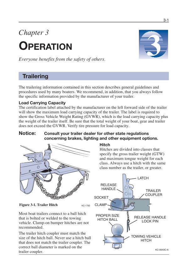
3-1
Chapter 3
OPERATIONEveryone benefits from the safety of others.
Trailering
The trailering information contained in this section describes general guidelines andprocedures used by many boaters. We recommend, in addition, that you always followthe specific information provided by the manufacturer of your trailer.
Load Carrying CapacityThe certification label attached by the manufacturer on the left forward side of the trailerwill show the maximum load carrying capacity of the trailer. The label is required toshow the Gross Vehicle Weight Rating (GVWR), which is the load carrying capacity plusthe weight of the trailer itself. Be sure that the total weight of your boat, gear and trailerdoes not exceed the GVWR. Verify tire pressure for load capacity.
Notice: Consult your trailer dealer for other state regulationsconcerning brakes, lighting and other equipment options.
HitchHitches are divided into classes thatspecify the gross trailer weight (GTW)and maximum tongue weight for eachclass. Always use a hitch with the sameclass number as the trailer, or greater.
Most boat trailers connect to a ball hitchthat is bolted or welded to the towingvehicle. Clamp-on bumper hitches are notrecom mended.
The trailer hitch coupler must match thesize of the hitch ball. Never use a hitch ballthat does not match the trailer coupler. Thecorrect ball diameter is marked on thetrailer coupler.
3
KC-1700
KC-0043C-A
SOCKET
RELEASEHANDLE
TOWING VEHICLEHITCH
PROPER SIZEHITCH BALL
CLAMP
TRAILER COUPLER
RELEASE HANDLELOCK PIN
LATCH
Figure 3-1. Trailer Hitch
Chapter 3_10: Chapter 3 doc.qxd 11/3/09 11:25 AM Page 1
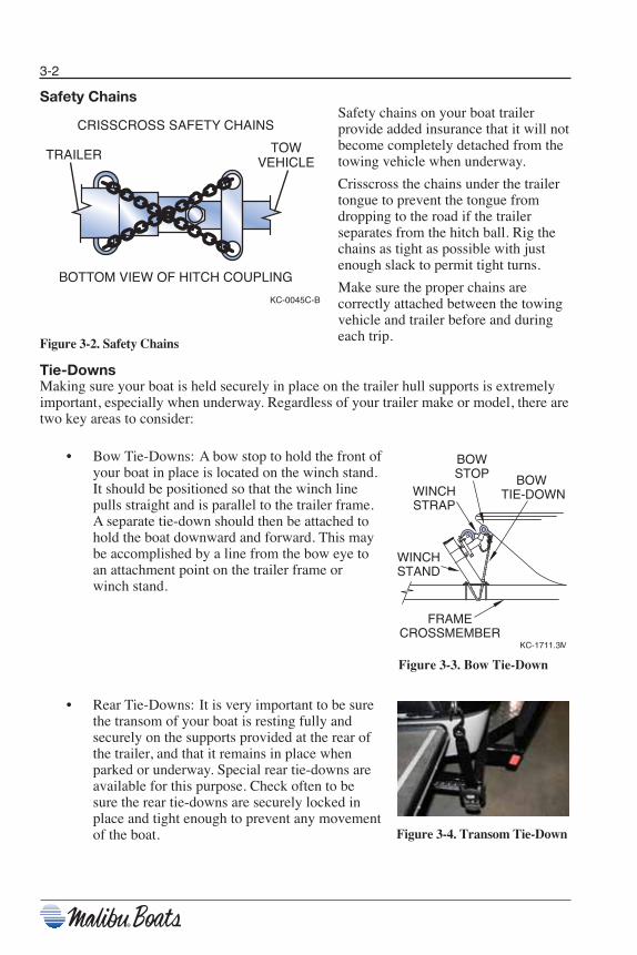
3-2
Safety ChainsSafety chains on your boat trailerprovide added insurance that it will notbecome completely detached from thetowing vehicle when underway.
Crisscross the chains under the trailertongue to prevent the tongue fromdropping to the road if the trailerseparates from the hitch ball. Rig thechains as tight as possible with justenough slack to permit tight turns.
Make sure the proper chains arecorrectly attached between the towingvehicle and trailer before and duringeach trip.Figure 3-2. Safety Chains
Tie-DownsMaking sure your boat is held securely in place on the trailer hull supports is extremelyimportant, especially when underway. Regardless of your trailer make or model, there aretwo key areas to consider:
• Bow Tie-Downs: A bow stop to hold the front ofyour boat in place is located on the winch stand.It should be positioned so that the winch linepulls straight and is parallel to the trailer frame.A separate tie-down should then be attached tohold the boat downward and forward. This maybe accomplished by a line from the bow eye toan attachment point on the trailer frame orwinch stand.
• Rear Tie-Downs: It is very important to be surethe transom of your boat is resting fully andsecurely on the supports provided at the rear ofthe trailer, and that it remains in place whenparked or underway. Special rear tie-downs areavailable for this purpose. Check often to besure the rear tie-downs are securely locked inplace and tight enough to prevent any movementof the boat. Figure 3-4. Transom Tie-Down
Figure 3-3. Bow Tie-Down
KC-0045C-B
TRAILER TOWVEHICLE
CRISSCROSS SAFETY CHAINS
BOTTOM VIEW OF HITCH COUPLING
Chapter 3_10: Chapter 3 doc.qxd 11/3/09 11:25 AM Page 2
3-3
Backing the TrailerBacking the boat trailer may sometimes be a difficult task. It is recommended that youpractice backing the trailer in a vacant lot or open area before attempting it at a congestedboat launch.
Follow these basic rules when backing:
1) Turn the front vehicle wheels in the opposite direction in which the trailer is totravel.
2) Back vehicle normally once the trailer turn is started.3) Have your vehicle equipped with a right hand mirror, as required by law when
towing.
LaunchingFollowing are some helpful tips to assist you with launching your boat:
• Before launching, check the type and condition of the ramp. Ramps are usuallymade of cement but often times are made of asphalt or even sand. When wet,these ramps can get very slick and can cause additional difficulties whenlaunching your boat.
• Have someone assist you when backing your boat. Back the trailer to the edge ofthe water and stop. Be sure to properly secure your vehicle.
• Prepare for placing the boat in the water by removing any tie-down straps,disconnecting tail light connections, and attaching a line to the bow eye fitting.If you are using an outboard, be sure that the outboard unit is trimmed up. Besure to reinstall the bilge drain plug if it has been removed.
• To launch, back the trailer into the water to a point where the boat will clear thebottom. Stop and secure the vehicle.
• Unlock the winch line from the boat. Push the boat into the water and have yourassistant guide the boat with the bow line.
• Once the boat is cleared of the trailer, pull your vehicle out of the water and parkit.
Reloading ProceduresTo reload, repeat the unloading procedures in reverse. Other important tips to rememberare:
• Try to idle coast onto the trailer; do not power onto the trailer.• When pulling the boat onto the trailer, be sure the boat is centered as much as
possible. The distance between the boat and runner board should beapproximately equal on both sides.
• Make sure the boat is securely in place before moving the trailer.
Chapter 3_10: Chapter 3 doc.qxd 11/3/09 11:25 AM Page 3

3-4
Warning LabelsWarning labels are displayed at various locations throughout your new Malibu to pointout safety hazards. It is important that you take the time to locate these labels. Do notremove or cover warning labels. Replace when illegible.
9
Figure 3-5. Warning Labels
Chapter 3_10: Chapter 3 doc.qxd 11/4/09 4:13 PM Page 4

Warning Label LocationsRefer to the diagrams below for the location of each label.
3-5
Chapter 3_10: Chapter 3 doc.qxd 11/3/09 11:25 AM Page 5
3-6
Load CapacityThe U.S. Coast Guard and most maritime authorities require that boats under 20 ft have acertification or builder’s plate stating the number of persons and maximum weight a boatwill handle safely under normal conditions. The certification is attached near the helmforward of the throttle. Overloading is a violation. Do not carry more weight orpassengers than indicated on the plate. The presence of the plate does not relieve theowner/operator from responsibility for using common sense and sound judgment.
Never exceed the load capacity and distribute weight evenlybetween bow and stern, and port to starboard.
SWAMPING HAZARDOverloading may reduce the stability and seaworthiness ofthe boat.
• The weight of all persons and gear including non-factory fitted ballast bags, waterbladders, ballast tanks and fat sacks should never exceed the maximum weightcapacity listed on the capacity label specified by the U.S. Coast Guard or yourlocal maritime authority.
• Add the weight of water contained in non-factory installed ballast bags or tanksto the weight of the persons and gear. When determining total weight on board,calculate the weight of water at 9 lbs/gal (1.1 kg/L).
Malibu Boats reminds you that when your boat is fully loaded with the maximum numberof persons and gear as indicated on the capacity plate, boat speed and performance willbe affected. Operate a boat in this condition with extra care.
Malibu Boats designs and engineers our boats to have the best possible performance atsea level with factory-installed equipment. For this reason, it is likely your boat can beequipped or loaded in a way that can restrict its performance when operated at higherelevations. Not all available options may be able to be utilized under these conditions.Consult your dealer for more information.
Chapter 3_10: Chapter 3 doc.qxd 11/5/09 10:36 AM Page 6
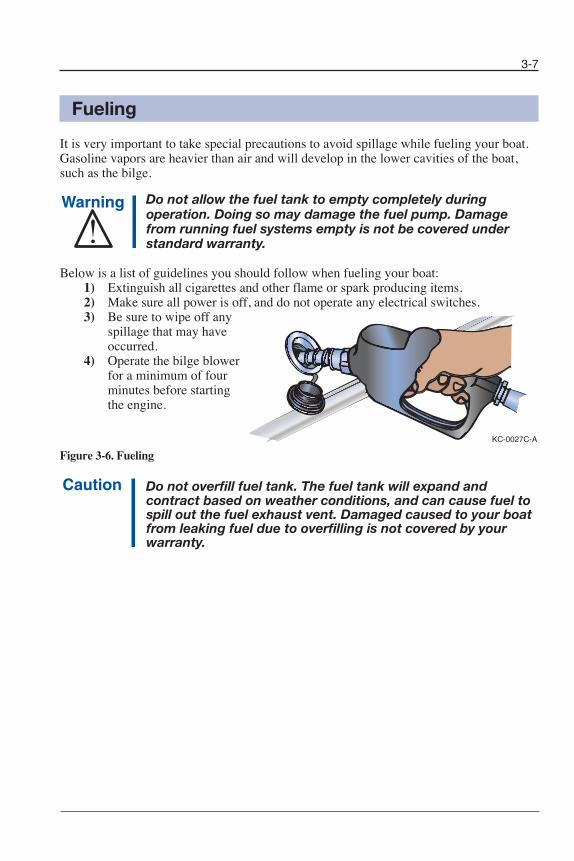
3-7
Fueling
It is very important to take special precautions to avoid spillage while fueling your boat.Gasoline vapors are heavier than air and will develop in the lower cavities of the boat,such as the bilge.
Do not allow the fuel tank to empty completely duringoperation. Doing so may damage the fuel pump. Damagefrom running fuel systems empty is not be covered understandard warranty.
Below is a list of guidelines you should follow when fueling your boat:1) Extinguish all cigarettes and other flame or spark producing items.2) Make sure all power is off, and do not operate any electrical switches.3) Be sure to wipe off any
spillage that may haveoccurred.
4) Operate the bilge blowerfor a minimum of fourminutes before startingthe engine.
Figure 3-6. Fueling
Do not overfill fuel tank. The fuel tank will expand andcontract based on weather conditions, and can cause fuel tospill out the fuel exhaust vent. Damaged caused to your boatfrom leaking fuel due to overfilling is not covered by yourwarranty.
KC-0027C-A
Chapter 3_10: Chapter 3 doc.qxd 11/3/09 11:25 AM Page 7

3-8
Starting
First Start-Up of the DayOn the first start-up of the day, you may find it beneficial to “key up” once or twice toprime the fuel system prior to cranking the engine to start. The fuel system pressure willdrop after a few hours of non-use. To prevent long crank times when starting for the firsttime, turn the key ON once to prime the fuel system.
This is a “High Pressure” fuel system. If you ever smell a strong fuel odor, shut downimmediately and inspect for leaks.
Notice: The PIT fuel system is not to be serviced by anyone other thana Malibu Factory Trained and Certified Technician. Special toolsand training are required to service this fuel system.
Pay close attention to the information regarding the break-in period listed in your engineowner’s manual. Top engine performance is dependent upon following the guidelineslisted.
Pre-Start ChecklistA routine pre-starting procedure should always be carried out before the first start-up ofthe day. Below is a list of basic, necessary checks to perform before starting your engine.
1) Replace drain plugs.2) Check oil and transmission fluid levels.3) Check fuel supply.4) Inspect the engine compartment for water or fuel leaks.5) Operate bilge pump until bilge is dry.6) Operate blower for a minimum of four minutes to expel fumes.
Chapter 3_10: Chapter 3 doc.qxd 11/3/09 11:25 AM Page 8
3-9
Starting the EngineMalibu boats are equipped with sensors that constantly monitor various functions of theboat. Certain functions, if outside of pre-determined operating parameters, may activatean alarm located under the dash. When the ignition key is turned ON, the alarm willsound to indicate it is operating. Once the engine is running, the alarm should be offunless a problem is detected. If the alarm sounds during operation, stop the boat as soonas possible and turn off the engine. Investigate and correct the problem before returningto operation. Pressing the ENTER button on the display will silence the alarm for fourminutes. Following is a list of monitored functions that can activate the alarm:
Engine Oil Alarm:RPMs above 300 and below 1000 with oil pressure below 4 psi.RPMs above 1000 with oil pressure below 18 psi.
Engine Temperature Alarm:RPMs above 300 with temperature above 203° F. Alarm will reset when enginecools below 198° F.
Battery Voltage Alarm:Voltage drops below 11 V.Voltage is above 16 V.
Water Depth Alarm:Water is shallower than water depth alarm setting.
Refer to Section 4, Care and Maintenance, Electrical, for more information on the alarm.Please refer to your engine owner’s manual for the proper starting procedures.
Chapter 3_10: Chapter 3 doc.qxd 11/3/09 11:25 AM Page 9
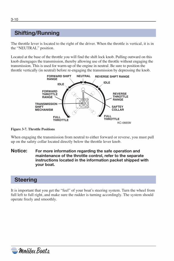
3-10
Shifting/Running
The throttle lever is located to the right of the driver. When the throttle is vertical, it is inthe “NEUTRAL” position.
Located at the base of the throttle you will find the shift lock knob. Pulling outward on thisknob disengages the transmission, thereby allowing use of the throttle without engaging thetransmission. This is used for warm-up of the engine in neutral. Be sure to position thethrottle vertically (in neutral) before re-engaging the transmission by depressing the knob.
Figure 3-7. Throttle Positions
When engaging the transmission from neutral to either forward or reverse, you must pullup on the safety collar located directly below the throttle lever knob.
Notice: For more information regarding the safe operation andmaintenance of the throttle control, refer to the separateinstructions located in the information packet shipped withyour boat.
Steering
It is important that you get the “feel” of your boat’s steering system. Turn the wheel fromfull left to full right, and make sure the rudder is turning accordingly. The system shouldoperate freely and smoothly.
Chapter 3_10: Chapter 3 doc.qxd 11/3/09 11:25 AM Page 10

3-11
Figure 3-8. Turning with a Rudder
The steering system must be in good operating condition forsafe boat operation. Frequent inspection, lubrication, andadjustment by your dealer is recommended.
All boats have a tendency to wander somewhat at slow speeds. A natural reaction to thiseffect is to steer the boat back and forth in an attempt to compensate for wandering.Invariably, the compensation will result in oversteer and only worsen the effect. Keep thesteering wheel in the center position, the boat will wander back and forth somewhat, butthe overall course will be a straight one.
KC-0199-A
BACKING TO LEFTTurn wheel to left—Stern will pull to left.
RIGHT TURNTurn wheel to right—Sternwill move to left.
LEFT TURNTurn wheel to left—Sternwill move to right.
Chapter 3_10: Chapter 3 doc.qxd 11/3/09 11:25 AM Page 11

3-12
Maneuvering TechniquesSteering response depends on three factors: engine position, motion and throttle.
Like an automobile, high speedmaneuvering is relatively easy andtakes little practice to learn. Slowspeed maneuvering, on the otherhand, is far more difficult andrequires time and practice to master.
When making tight maneuvers, it isimportant to understand the effects ofturning. Since both thrust andsteering are at the stern of the boat,the stern will push away from thedirection of the turn. The bowfollows a smaller turning circle thanthe stern.
The effects of unequal propellerthrust, wind, and current must also bekept in mind. While wind and currentmay not always be present, anexperienced boater will use them to
his advantage. Unequal thrust is an aspect shared by all single engine propeller-drivenwatercraft. A counterclockwise rotation propeller tends to cause the stern of the boat,steering in the straight ahead position, to drift to port when going forward, and tostarboard when going backward. At high speed, this effect is usually unnoticed, but atslow speed; especially during backing, it can be powerful. For this reason, many veteranboaters approach the dock with the starboard side of the boat toward the dock, if possible,since the stern of the boat will drift starboard when reverse thrust is applied.
Stopping
When stopping the boat, it is important to remember there are no brakes to allow comingto a complete, immediate stop. To stop your boat, anticipate ahead of time and beginslowing down by pulling back on the throttle.
Once the throttle is in neutral and the engine has stopped pulling the boat forward, it maybe necessary to pull the throttle into reverse to further slow the forward momentum of theboat. The reverse thrust of the engine will decrease the forward speed and slow the boatdown to a safer maneuvering speed. Never shift the transmission into reverse if the boat ismoving faster than 2 MPH (3.2 km/h).
Do not use the engine stop switch for normal shut down.Doing so may impair your ability to restart the engine quicklyor may create a hazardous swamping condition.
KC-0201-A
BOWCIRCLE
STERNCIRCLE
Figure 3-9. Stern Push
Chapter 3_10: Chapter 3 doc.qxd 11/4/09 1:15 PM Page 12

3-13
Docking
Docking procedures for the new boat owner usually bring surprising results. Remember,operate your boat at slow speeds to avoid accidents and practice docking to gainexperience and confidence.
Once away from the dock, practice docking in open water with an imaginary dock. Pullup to the dock at a slow rate of speed. Shift the boat into neutral and drift slowly towardthe dock. Shift the boat into reverse slightly to slow or stop the boat altogether.
Never use your hand, arm or other part of your body betweenthe dock and boat or attempt to keep the boat from hittingthe dock. The boat could push against the dock, causingsevere injury.
Follow these guidelines when docking:
• Approach docks with the starboard side of the boat if possible.• Come to a stop a short distance from the dock, then proceed slowly.• Have fenders, mooring lines and crew ready.• Observe how the wind and current are moving your boat. Approach the dock
with the boat pointed into the wind, if possible. If the wind or current is pushingyou away from the dock, use a sharper angle of approach. If you must approachthe dock downwind or down current, use a slow speed and shallow angle. Beready to reverse to stop and maintain position.
• If there is no wind or current, approach the dock at a 10 to 20 degree angle.• If possible, throw a line to a person on the dock and have that person secure a
bow line.• With the bow secure, swing the stern in with the engine, or pull it in with a boat
hook.
Figure 3-10. Docking with Wind/Current
KC-0200C-A
WIND or CURRENT WIND or CURRENT
Chapter 3_10: Chapter 3 doc.qxd 11/3/09 11:25 AM Page 13

3-14
Before tying up the boat, be sure to use enough fenders to protect the boat from damage.If possible, tie up with the bow toward the waves with a good-quality, double-braidednylon line. Tie up only to the lifting or tie-down eyes; never use the handrails orwindshield frames. If the boat is to be moored for a long period of time, use chafingprotectors on lines to protect the gelcoat finish. Leave a little slack in the lines to allowfor some wave movement or tidal action if applicable.
The foredeck handrails should only be used for tying a “Jackline” in an emergencysituation. If possible, tie up your boat with the bow toward the waves and leave a littleslack in the lines to allow for movement from waves or the tide.
Follow these guidelines when departing:
• Very slowly shift into forward at idle speed.• When the stern moves away from the dock, turn the engine away from the dock.• Cast off bow line and back away.
If the wind or current is pushing away from the dock, cast off all lines and allow to driftuntil you are clear.
High-Speed Operation
A great deal of caution must be exercised when operating any boat at high speeds. This isparticularly true during turns. Gradual turns can be completed at high speed by acompetent driver, but it must be emphasized that sudden turns at any speed, particularlyat high speed can be especially dangerous. It is possible to throw passengers from theirseats and even from the boat if caution is not exercised.
Towing a Skier
Water skiing is a collective effort involving driver, observer and skier. The degree ofunderstanding and cooperation between them directly determines the success andenjoyment of the venture. All must understand that the skier is an extension of the boat.The driver is no longer responsible for a boat that is 20 ft long, but closer to 95 ft. Oncethis is understood, you are underway to a safe and secure adventure together. A healthyrespect for Common Sense Rules of water skiing safety on the part of the skier, driverand observer will ensure the risk of skiing accidents is kept to a minimum at all levels ofparticipation.
A moderate ability to swim is advisable for waterskiers, but swimming ability is nosubstitute for a well-fitting life jacket. The wearing of a life jacket or personal flotationdevice (PFD) is essential even for expert swimmers. The jacket should be Type III,approved by the U.S. Coast Guard and designated as a ski jacket. The jacket should fitsnugly, otherwise it could slip up over the skier if the skier should happen to fall at highspeed.
Chapter 3_10: Chapter 3 doc.qxd 11/3/09 11:25 AM Page 14
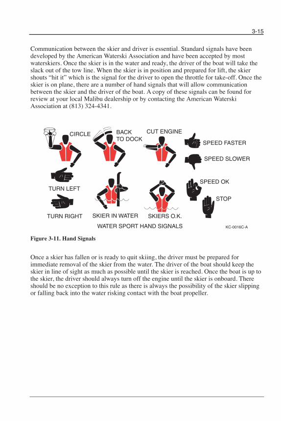
3-15
Communication between the skier and driver is essential. Standard signals have beendeveloped by the American Waterski Association and have been accepted by mostwaterskiers. Once the skier is in the water and ready, the driver of the boat will take theslack out of the tow line. When the skier is in position and prepared for lift, the skiershouts “hit it” which is the signal for the driver to open the throttle for take-off. Once theskier is on plane, there are a number of hand signals that will allow communicationbetween the skier and the driver of the boat. A copy of these signals can be found forreview at your local Malibu dealership or by contacting the American WaterskiAssociation at (813) 324-4341.
Figure 3-11. Hand Signals
Once a skier has fallen or is ready to quit skiing, the driver must be prepared forimmediate removal of the skier from the water. The driver of the boat should keep theskier in line of sight as much as possible until the skier is reached. Once the boat is up tothe skier, the driver should always turn off the engine until the skier is onboard. Thereshould be no exception to this rule as there is always the possibility of the skier slippingor falling back into the water risking contact with the boat propeller.
CIRCLE
SPEED OKTURN LEFT
TURN RIGHT
BACK TO DOCK
STOP
SKIER IN WATER
WATER SPORT HAND SIGNALS
SPEED FASTER
CUT ENGINE
SPEED SLOWER
SKIERS O.K.
KC-0016C-A
Chapter 3_10: Chapter 3 doc.qxd 11/3/09 11:25 AM Page 15
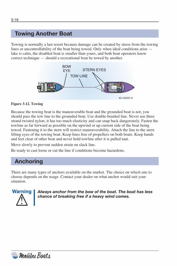
3-16
Towing Another Boat
Towing is normally a last resort because damage can be created by stress from the towinglines or uncontrollability of the boat being towed. Only when ideal conditions arise —lake is calm, the disabled boat is smaller than yours, and both boat operators knowcorrect technique — should a recreational boat be towed by another.
Figure 3-12. Towing
Because the towing boat is the maneuverable boat and the grounded boat is not, youshould pass the tow line to the grounded boat. Use double-braided line. Never use threestrand twisted nylon; it has too much elasticity and can snap back dangerously. Fasten thetowline as far forward as possible on the upwind or up current side of the boat beingtowed. Fastening it to the stern will restrict maneuverability. Attach the line to the sternlifting eyes of the towing boat. Keep lines free of propellers on both boats. Keep handsand feet clear of other boat and never hold towline after it is pulled taut.
Move slowly to prevent sudden strain on slack line.
Be ready to cast loose or cut the line if conditions become hazardous.
Anchoring
There are many types of anchors available on the market. The choice on which one tochoose depends on the usage. Contact your dealer on what anchor would suit yoursituation.
Always anchor from the bow of the boat. The boat has lesschance of breaking free if a heavy wind comes.
KC-0202C-A
TOW LINE
BOWEYE STERN EYES
Chapter 3_10: Chapter 3 doc.qxd 11/3/09 11:25 AM Page 16
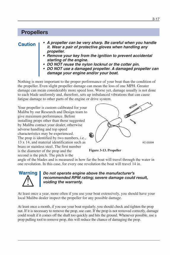
3-17
Propellers
• A propeller can be very sharp. Be careful when you handleit. Wear a pair of protective gloves when handling anypropeller.
• Remove your key from the ignition to prevent accidentalstarting of the engine.
• DO NOT reuse the nylon locknut or the cotter pin.• DO NOT use a damaged propeller. A damaged propeller can
damage your engine and/or your boat.
Nothing is more important to the proper performance of your boat than the condition ofthe propeller. Even slight propeller damage can mean the loss of one MPH. Greaterdamage can mean considerably more speed loss. Worse yet, damage usually is not doneto each blade uniformly and, therefore, sets up imbalanced vibrations that can causefatigue damage to other parts of the engine or drive system.
Your propeller is custom calibrated for yourMalibu by our Research and Design team togive maximum performance. Beforeinstalling props other than those suggestedby Malibu contact your dealer, otherwiseadverse handling and top speedcharacteristics may be experienced. The prop is identified by two numbers, i.e.,13 x 14, and material identification such asbrass or stainless steel. The first numberis the diameter of the prop and thesecond is the pitch. The pitch is theangle of the blades and is measured in how far the boat will travel through the water inone revolution. In this case, for every one revolution the boat will travel 14 in.
Do not operate engine above the manufacturer’srecommended RPM rating; severe damage could result,voiding the warranty.
At least once a year, more often if you use your boat extensively, you should have yourlocal Malibu dealer inspect the propeller for any possible damage.
At least once a month, if you use your boat regularly, you should check and tighten the propnut. If it is necessary to remove the prop, use care. If the prop is not removed correctly, damagecould result if it comes off the shaft too quickly and hits the ground. Whenever possible, use aprop pulling tool to remove prop, this will reduce the chance of damaging the prop.
KC-2220M
Figure 3-13. Propeller
Chapter 3_10: Chapter 3 doc.qxd 11/3/09 11:25 AM Page 17

3-18
Removal1) Remove the cotter pin from the propeller shaft and discard.2) Wedge a piece of 1" x 4" wood between the propeller blade and the starboard side of
the strut and rudder.3) Loosen the nylon locknut and unthread it until it is flush with the end of the prop shaft.4) Use a propeller puller to separate the prop from the taper on the shaft. Holding the
prop with one hand, remove the nylon locknut and discard.5) Remove the propeller, then remove the key from the keyway. Inspect the keyways
and key for any damage.
InstallationBefore installing the prop, look at the keyway on the shaft and in the propeller. The keyshould slide freely in both keyways. DO NOT use the prop nut to advance the prop ontoshaft.
If the key has slight damage or burrs, remove them by filing the flat sides or replace thekey. DO NOT file the key beyond its normal shape or size.1) Rotate the shaft until the keyway is “up.”2) Place the key in the shaft keyway. Align the keyway in the prop to the key. The prop
will only slip on in one direction. Once the prop starts to go on the shaft, push thepropeller “solidly” on the shaft and make sure you feel that it is seating properly.
3) Wedge a piece of 1" x 4" wood between the propeller blade and the port side of thestrut and rudder.
4) Install a new nylon locknut and torque the nut to maximum of 30 ft-lbs (40.7 N•m).5) Install new cotter pin. Bend the retaining ends of the cotter pin in the opposite
directions. Make sure the cotter pin is snug and cannot rotate.
Malibu Exclusive Adjustable Rudder System
Your Malibu steering is custom calibrated at the Malibu factory at the time of manufacturing. However, it may benecessary from time to time to adjust the steering due to normaloperations. Malibu Boats’ unique adjustment feature allows customcalibration to your specific driving needs. The Malibu AdjustableRudder system allows you to increase or decrease the amount of loadthat is typically on the steering system.
If it is determined that your rudder needs adjustment, you can do soby adjusting tunable feature located on the rudder surface. Locatethe 1/8" set-screws. Loosening the set-screws will release theadjustment tab. If your boat pulls to the right, turn the tab to theright 1/8th to 1/4". Do not move beyond this point. Only minor adjustments are needed tomake a correction. Note that it may take more than one adjustment to get the desiredsetting. Tighten the set-screws when adjustment is completed.
Figure 3-14. Adjustable Rudder
Chapter 3_10: Chapter 3 doc.qxd 11/4/09 1:16 PM Page 18
3-19
Make sure the set-screws are tightened after eachadjustment. Failure to tighten the set-screws could causeerratic steering and serious damage could result. If you areunsure of the correct procedure to conduct this adjustment,it is recommended that you return your boat to your localMalibu Boat dealership for assistance.
Corrosion Protection
Galvanic corrosion (electrolysis), is the break-up of metals do to the effects of electrolyticaction. When two dissimilar metals are immersed in a conductive fluid such as salt water,an electric current is produced, similar to that of a battery. As the current flows, it takeswith it tiny bits of the softer metal. If not stopped, a great deal of damage can occur.
If you operate your boat in salt or brackish waters, you should have your boat equippedwith a transom mounted zinc anode to prevent damage to the parts coming in contactwith the water. The zinc anode being the softer metal will deteriorate and erode muchfaster than the other metals in the boat. Inspect the anode periodically and replace asneeded. Consult your local Malibu dealer for this part.
Saltwater CorrosionIf you use your boat in salt or brackish water, wash the entire boat, including trailer andtower (if fitted), thoroughly with a mild detergent and rinse with fresh water afterEVERY USE. Apply a corrosion inhibitor to all hardware regularly. Consult your dealerfor products suitable for the marine saltwater environment and proper usage instructions.
Malibu strongly recommends freshwater internal engine flushing after using the boat insalt, polluted or brackish waters. Flush the entire cooling system with fresh water for atleast five minutes after use in these waters. See your Malibu dealer for appropriateflushing devices and additives.
Notice: Salt water is commonly very harsh on all components of boat.Saltwater corrosion is not covered under your Malibu Boat orIndmar warranties. It is the boat owner’s responsibility tounderstand and ensure they have taken proper precautions tosafeguard boat.
Chapter 3_10: Chapter 3 doc.qxd 11/5/09 10:37 AM Page 19

3-20
Notes
Chapter 3_10: Chapter 3 doc.qxd 11/3/09 11:25 AM Page 20
4Chapter 4
CARE AND MAINTENANCEThe following guidelines discussed in this section will protect the investment you have made by preserving the beauty and performance of your new boat for years to come.
Interior
CarpetYour Malibu boat is equipped with a top quality, all-weather indoor/outdoor carpet. It isessentially waterproof and fade resistant. Occasional vacuuming and scrubbing with soapand water will remove embedded dirt and grit.
VinylAll upholstery items aboard your boat are made of a tough marine vinyl that is easilycleaned with a mild detergent and warm water. After washing the vinyl, be sure to dry it thoroughly.
Our materials are mildew resistant, but there are no products available to us that aremildew proof. Therefore, we also recommend that you dry the upholstery thoroughly atthe end of each day’s boating activity to prevent mildew which will rot the upholsterythreads and backing. We also recommend that you tip up all seat base cushions on edgeafter each use to allow any accumulated water to drain.
In some instances, color or dye transfer can occur when wetclothing comes in contact with vinyl. If this occurs, the vinylshould be cleaned immediately to avoid permanent staining.Unfortunately, due to the porous nature of the upholstery,you may find that the dye has set into the vinyl surface, andyou cannot remove it. If this should occur, it is recommendedthat you contact Final Finish/MSG to get assistance incleaning.
Upholstery finish stains caused by secondary sources are notcovered under your Malibu Boats Warranty.
4-1
Chapter 4_10: Chapter 4 doc.qxd 11/3/09 11:41 AM Page 1

4-2
It is important to keep your vinyl clean at all times. Some substances can stain the vinyl ifyou leave them on for even a short period. Remove any contaminant and clean the areaimmediately. Some household cleaners, powdered abrasives, steel wool, industrial cleaners,dry cleaning fluids and lacquer solvents can damage and discolor. Failure to care for yourvinyl properly, or use of improper cleaners may damage the vinyl and void your warranty.
DO NOT use products such as acetone, ArmorAll®, bleach, baking soda, Fantastik®,Formula 409®, gasoline, kerosene, Murphy® Oil Soap, Simple Green®, Son of a Gun!® orany silicone based protectants. DO NOT clean your vinyl with power washers, as they cangenerate pressures up to 3,500 psi and could damage the surface of your interior.
Common stains and steps to treat:
Type of Stain Step #1 Step #2 Step #3General care A BDirt buildup A BBallpoint ink* B AChewing gum B ACoffee, tea, chocolate B AGrease C B AHousehold soil A BKetchup A BLatex paint A BLipstick C A BMildew or wet leaves* B AMotor oil C B AOil-based paint C B APermanent marker* B ASpray paint B ASuntan lotion* A BTar/asphalt C B AYellow mustard A B
A. Medium-soft brush, warm, soapy water, rinse/dryB. 303 Fabric and Vinyl Cleaner®, rinse/dryC. Wipe or scrape off excess (chill gum with ice)
After all cleaning methods, rinse well with clear, warm water.
* Suntan lotion, tree pollen, wet leaves and some other products, including waxes, cancontain dyes that stain permanently.
The Plexiglas walk-through windblock should only be cleaned with mild, soapy waterand a soft cloth. Ammonia-based or harsh chemical cleaners will damage the Plexiglas.
The same applies to the in-dash graphical display, the MaliView screen, gauges anddigital switch lenses. Only a damp, soft cloth with mild, soapy water should be used.Ammonia-based or harsh chemical cleaners will damage the lenses.
Chapter 4_10: Chapter 4 doc.qxd 11/3/09 11:41 AM Page 2
4-3
Exterior
Your Malibu boat is highly resistant to weathering, water pollution and minor scrapeswhich occur during normal use. However, regular care and maintenance of your boat is ageneral responsibility for all Malibu boat owners. By following the boat care instructionslisted below, you will be able to extend the life and beauty of your Malibu boat.
HardwareMost of the metal hardware on your boat consists of brass, stainless steel, or aluminumand should be cleaned on a periodic basis with soap and water. In fresh water, metalfittings and hardware should be sprayed regularly with a rust inhibitor and after every usein saltwater.
DO NOT use cleaners that are not intended for use on stainless steel. Glass, tile, counteror citrus cleaners can damage hardware permanently. Always follow cleaning, byapplying a high-quality metal polish or automotive wax after cleaning. Test products inan inconspicuous area before applying to the complete surface, especially if you are notfamiliar with the product.
All metal parts, including but not limited to tower accessories, board racks or speakercans, should be cleaned with mild soap and water frequently and waxed periodically. Acorrosion protectant is highly recommended on these components, especially for use inareas of or in proximity to salt/brackish water. Pitting, corrosion or oxidation is notcovered under warranty. Pitting is not the same as separation.
Fiberglass and GelcoatThe fiberglass hull and deck of your Malibu boat consist of a molded shell and exteriorgelcoat. The gelcoat protects the fiberglass shell and gives all Malibu boats a smooth andshiny surface. The following are some general instructions which will help you maintainyour boat’s sleek appearance:
1) Wash monthly or more frequently, depending on use. Use a mild dish washingsoap and lukewarm or cold water. Rinse your boat with fresh water and wipedown immediately to avoid water spots.
2) Wax the boat hull and deck after every three or four outings to decrease waterfriction and to lessen the potential for staining or spotting the gelcoat surface. Incases where the original gelcoat shine cannot be restored by waxing, hand buffthe surface using any commercial compound. Be sure to apply several coats ofwax over the area that has been polished.
Chapter 4_10: Chapter 4 doc.qxd 11/12/09 4:22 PM Page 3

4-4
Surface StainsStains can appear as a result of dust, road tar, plant sap, rust from metal fittings and othermaterials coming in contact with your boat’s exterior. Listed below is a step-by-stepprocedure to remove stains from your boat:
1) Wash area with dish washing soap2) Apply a mild cleanser on a small area (3 x 3 ft) 3) Rinse with fresh water4) Buff with a fine rubbing compound5) Wax
If the stain is not removed by the dish washing soap or mild cleanser, then the nextprocedure is to use either denatured or rubbing alcohol. Common rubbing alcohol isexcellent for removing stains.
ScratchesScratches to the gelcoat sometimes occur during normal use. Your dealer can usuallyrestore the gelcoat to like-new condition.
Underwater CorrosionCorrosion occurs in saltwater conditions from the interaction of the saltwater and thedirect current of the battery. To prevent corrosion, it is important to keep the bilge area asdry and clean as possible.
Care for Boats that are MooredDue to gelcoat discoloration, osmosis (blistering) and algae growth, it is not recommendedthat you leave your boat moored for long periods of time. If your boat will be moored infresh water or saltwater for extended periods of time, you should do the following:
1) Haul-out and clean your boat regularly (every 14 to 21 days). Use soap, waterand plenty of elbow grease.
2) Apply wax after cleaning.
You should also check with your local Malibu dealer about anti-fouling paint and otherproducts that can be applied to the hull bottom below the water line.
Teak WoodCare must be taken to keep teak wood from turning gray or rough. The roughing becomesmore apparent as the moisture evaporates and dries out.
It is suggested that you use teak or mineral oil treatments at least four times a year tomaintain the appearance of your swim platform. Use a high-quality teak oil which can bepurchased at your local Malibu dealership.
For additional information on care, maintenance and warranty on your swim platform,please see the information provided in your Owners Packet.
Notice: Teak sealers and cleaners can damage other materials. Makesure you thoroughly remove any spills or excess. Teak shouldnot be varnished. The natural oils in teak cause poor adhesion.
Avoid fire or explosion onboard. DO NOT store rags used to treat teak onboard. Store or dispose of rags properly ashore.
Chapter 4_10: Chapter 4 doc.qxd 11/3/09 11:41 AM Page 4

Figure 4-1. LS7 Engine
Figure 4-2. Monsoon 340 Engine
Figure 4-3. LS3 Engine
Figure 4-4. 8.1L Vortec MPFI Engine
Figure 4-5. 5.7L LCR Engine
4-5
Engine/Drive Train EngineFor information on engine service, maintenance and break-in period, please refer to yourengine owner’s manual. The Required Maintenance Schedule included in this manual coversthe minimum maintenance required for Indmar engine packages. The MaintenanceWorksheet included in this manual outlines safety checks, lubrication and general servicethat should be performed at regular intervals. It is recommended that any engine replacementparts used for maintenance or repair be supplied by an authorized Malibu dealer. Do notoperate the LS3 engine in salt or brackish water unless it is equipped with a freshwatercooling system.
Chapter 4_10: Chapter 4 doc.qxd 11/3/09 11:41 AM Page 5
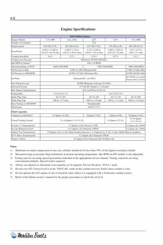
Engine Specifications
Notes
1) Minimum recorded compression in any one cylinder should not be less than 70% of the highest recorded cylinder.
2) Measured using an accurate shop tachometer at normal operating temperature. Idle RPM on EFI models is not adjustable.
3) Timing must be set using special procedures indicated in the appropriate service manual. Timing cannot be set usingconventional methods. Special tool(s) required.
4) Always use dipstick to determine exact quantity of oil required. Do not fill above “FULL” mark.
5) Do not over fill. Correct level is at the “Full Cold” mark on the coolant recovery bottle when coolant is cold.
6) Do not operate the LS3 engine in salt or brackish water unless it is equipped with a freshwater cooling system.
7) Refer to the Indmar owner’s manual for the proper procedure to check the oil level.
Engine Models 5.7L MPI 6.2L (383) LS7 LS36 8.1L MPI
Number of Cylinders V-8
2010 Malibu Engines
Fluid Capacities
Displacement 350 CID (5.7L) 383 CID (6.3L) 427 CID (7.0L) 376 CID (6.2L) 496 CID (8.1L)
Crankcase (with Filter)4 5.5 Quarts (5.25L) 8 Quarts (7.6L)7 7 Quarts (6.6L) 10 Quarts (9.5L)
Indmar Vee Transmission4 2.0 Quarts 10 oz (2.2L) Main Gearbox Dexron 3, 1.0 Quart 8 oz (1.2L) V-drive Mobil Delvac Synthetic
ZF V-Drive Transmission4 4.2 Quarts (4L) Pennzoil 15W40
Walter V-Drive 0.5 Quart (0.5L) Pennzoil SAE 30 Motor Oil
In-Line 1:1 Transmission4 1.7 Quarts (1.6L) Dexron 3 ATF 4.2 Quarts (4L) 15W40
In-Line Reduction Gear4 2.12 Quarts (2L) Pennzoil 15W40 4.2 Quarts (4L) 15W40
14-16 Quarts (13.2-15.1L)Closed Cooling System5 12-14 Quarts (11.4-13.3L) 16 Quarts (15.1L)
Spark Plug Gap .060 in. (1.5 mm) .040 in. (1.0 mm) .050 in. (1.3 mm) .040 in. (1.0 mm)
Base Timing at 1000 RPM3 Nonadjustable
Thermostat 160°F (71°C)
Firing Order 1-8-4-3-6-5-7-2 1-8-7-2-6-5-4-3
Spark Plug Type AC 41-101 AC 41-104 AC 41-110 AC 41-983
Electrical System 12 Volt DC Negative (-) Ground
Min. Battery Requirements 650 cca/700 mca/120 Ah
Operating Range at WOT 4600-5200 RPM 5200-5600 RPM 5000-5400 RPM
Oil Pressure at Idle 4 PSI (41 kPa) Minimum Hot 5 PSI (34 kPa) Min.
Oil Pressure at 2000 RPM 18 PSI (124 kPa) Minimum Hot 10 PSI (69 kPa) Min.
AC-PF454 (on engine) Pennzoil PZ3 (remote)
Idle RPM in Neutral2 650 ± 50 RPM
Compression Ratio 9.4:1 9.7:1 11.0:1 10.7:1 9.1:1
Compression Pressure1 Minimum 100 PSI (690 kPa)
4.0012 x 3.480 in. 4.0012 x 3.8 in. 4.125 x 4.00 in. 4.065 x 3.622 in. 4.25 x 4.37 in. (101.63 x 88.39 mm) (101.63 x 96.52 mm) (104.8 x 101.6 mm) (103.25 x 92 mm) (108 x 111 mm)
Oil Filter Pennzoil PZ3, AC-PF25
Bore/Stroke
Fuel Pump Pressure 60 PSI Minimum at Keyup (414 kPa)
4-6
Chapter 4_10: Chapter 4 doc.qxd 11/3/09 11:41 AM Page 6

TransmissionCheck fluid only with engine OFF and boat floating level, or level on trailer. Thetransmission dipstick is located on the top of the transmission. Dipsticks may be marked“FULL” or “H” (high) and “ADD” or “L” (low); maintain fluid level between the twomarks.
Check level immediately after turning engine off.Transmission fluid may be hot. Be careful not to burnyourself.
TRANSMISSION MODEL CAPACITY FLUID TYPEZF Hurth In-Line 450D 1.7 qt (1.6L) Pennzoil Dexron II, III or MERCONZF Hurth In-Line 450A 2.12 qt (2L) Pennzoil Dexron II, III or MERCONZF Hurth In-Line 630A 4.2 qt (4L) Pennzoil Dexron II, III or MERCONZF Hurth V-Drive 630V 4.2 qt (4L) Pennzoil Dexron II, III or MERCON
Do not overfill the transmission. Overfilling can damage thetransmission. Damage to your transmission due to too muchor too little fluid is not covered by your warranty.
Opera te boat approximately five minutes to warm the transmission fluid. Turn engine off and disconnect the enginesafety switch. Ensure throttle is neutral.
Notice: Check immediately after shutdown toprevent incorrect reading.
• Open engine compartment and locate transmissionfluid level dipstick.
• Remove dipstick and wipe with a clean rag. Quicklyre-insert the dipstick fully and immediately remove.Check the fluid level is at the full warm mark on thestick.
• Add or remove fluid as necessary to maintain the levelat the mark. Use only recommended automotivetransmission fluid. You will find recommended fluidtypes in your Indmar Owner’s Manual.
Figure 4-6. Typical Transmission Dipstick
HIGH (FULL)
LOW (ADD)
4-7
Chapter 4_10: Chapter 4 doc.qxd 11/3/09 11:41 AM Page 7
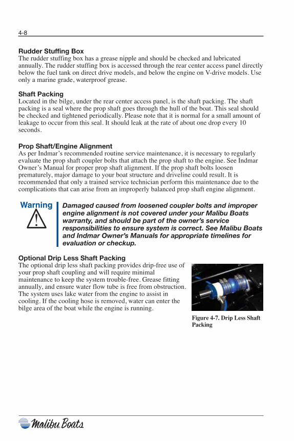
4-8
Rudder Stuffing BoxThe rudder stuffing box has a grease nipple and should be checked and lubricatedannually. The rudder stuffing box is accessed through the rear center access panel directlybelow the fuel tank on direct drive models, and below the engine on V-drive models. Useonly a marine grade, waterproof grease.
Shaft PackingLocated in the bilge, under the rear center access panel, is the shaft packing. The shaftpacking is a seal where the prop shaft goes through the hull of the boat. This seal shouldbe checked and tightened periodically. Please note that it is normal for a small amount ofleakage to occur from this seal. It should leak at the rate of about one drop every 10seconds.
Prop Shaft/Engine Alignment As per Indmar’s recommended routine service maintenance, it is necessary to regularlyevaluate the prop shaft coupler bolts that attach the prop shaft to the engine. See IndmarOwner’s Manual for proper prop shaft alignment. If the prop shaft bolts loosenprematurely, major damage to your boat structure and driveline could result. It isrecommended that only a trained service technician perform this maintenance due to thecomplications that can arise from an improperly balanced prop shaft engine alignment.
Damaged caused from loosened coupler bolts and improperengine alignment is not covered under your Malibu Boatswarranty, and should be part of the owner’s serviceresponsibilities to ensure system is correct. See Malibu Boatsand Indmar Owner’s Manuals for appropriate timelines forevaluation or checkup.
Optional Drip Less Shaft PackingThe optional drip less shaft packing provides drip-free use of your prop shaft coupling and will require minimalmaintenance to keep the system trouble-free. Grease fittingannually, and ensure water flow tube is free from obstruction.The system uses lake water from the engine to assist incooling. If the cooling hose is removed, water can enter thebilge area of the boat while the engine is running.
Figure 4-7. Drip Less ShaftPacking
Chapter 4_10: Chapter 4 doc.qxd 11/3/09 11:41 AM Page 8
Fuel System
Fuel SystemAll 2010 Malibu Boats are equipped with Pump-in-tank (PIT) fuel systems. This meansthe fuel pump is no longer mounted on the engine and is now located in the fuel tank.There are many benefits to using Pump-in-Tank; most notably is the prevention of vaporlock and improved filtration of contaminants.
This is a “High Pressure” fuel system. If you ever smell a strong fuel odor, shut downimmediately and inspect for leaks.
The PIT fuel system is not to be serviced by anyone otherthan a Malibu Factory Trained and Certified Technician.Special tools and training are required to service this fuelsystem.
Do not use fuel containing more than 15% MTBE. Also, fuel containing more than 10%ethanol or grain alcohol is not recommended. A higher percentage of either of the twofuel additives can cause damage to the engine and fuel system.
DO NOT mix MTBE and ethanol. Drain your tank, or use up as much of the old fuel asyou can before making the switch to E10. Once done, do not go back to MTBE gas. Also,drain the tank when storing the boat, and put in additives.
Does the gas you are buying have ethanol or MTBE? By law, roadside stations must putstickers on pumps designating whether the gas has ethanol and how much. A lot ofmarinas do not put up stickers, so ask.
Find out when your fuel provider switched to E10 and how it was done. Old fuel andwater should have been removed and the tanks cleaned to reduce the possibility of theethanol loosening up old sludge. If they mixed ethanol with gas, you could be pumping apotential disaster into your boat.
Mixing the two additives can and will cause damage to the engine and fuel system whichwill void all warranties supplied by Malibu Boats LLC, and Indmar Engine Company.
Refer to the engine owners manual for further information.
4-9
Chapter 4_10: Chapter 4 doc.qxd 11/3/09 11:41 AM Page 9

Electrical
Engine Circuit BreakerYour engine is equipped with a 35 AMP Circuit Breaker to protect the engine electricalsystem and components from overload, and is found on the lower right side of the engine.If your engine should loose power and will not crank, reset the breaker by firmly pressingthe red button (an audible sound will be heard). For additional engine electrical issues,see your Indmar Engine Owners Manual, or contact your Local Malibu dealership.
Main Circuit BreakerLocated adjacent to the battery is a 80 AMP CircuitBreaker. If your boats systems loose electrical power, and you have no dash gauges or your engine does not turn over, you will need to reset the breaker to restorepower to your boats systems. To reset, find breaker switch and depress until lever locks into position.
Power loss to the Main Breaker isan indication of serious issues toyour boats electrical and/orengine components Contact yourlocal dealer for evaluation ofthese components.
If additional loads are added to the dash feeder circuits, suchas amplifiers, tower lights, etc., this can overload the 80 AMPbreaker. Large loads over 20 AMPS should be wired directlyto the battery with proper overload protection.
Boat AlarmsMalibu boats are equipped with sensors that constantly monitor various functions of theboat. Certain functions, if outside of pre-determined operating parameters, may activatean alarm located under the dash. Both the engine Electronic Control Module (ECM) andthe dash gauge computer may activate the alarm.
If the ECM activates the alarm, it will store a trouble code in memory. Stop the boat assoon as possible and turn off the engine. You will need to have your Malibu dealer run adiagnostics test to repair the engine and clear any codes from memory. The ECM uses theengine oil pressure, engine temperature and transmission temperature switches for inputand parameters are stored in the ECM.
If the dash gauge computer activates the alarm, the Multi Function Display Panel willindicate the source of the problem. If the alarm sounds during operation, stop the boat assoon as possible and turn off the engine. You will need to have your Malibu dealer run adiagnostics test to repair the engine and clear any codes from memory. The dash gaugecomputer uses a separate set of sending units on the engine, fuel tank and depthtransducer for input and parameters are stored in the computer.
Refer to Section 3, Operation, Starting, for more information on the alarm.
4-10
Figure 4-8. Main Circuit Breaker
Chapter 4_10: Chapter 4 doc.qxd 11/3/09 11:41 AM Page 10
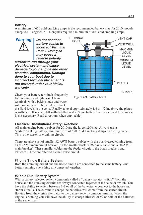
BatteryA minimum of 650 cold cranking amps is the recommended battery size for 2010 modelsexcept 8.1 L engines. 8.1 L engines require a minimum of 800 cold cranking amps.
Do not connectbattery cables toincorrect TerminalPost ±. Doing somay cause areverse polarity
current to run through yourelectrical system and causedamage to your engine and otherelectrical components. Damagedone to your boat due toincorrect terminal placement isnot covered under your Malibuwarranty.
Check your battery terminals frequentlyfor corrosion and tightness. Clean terminals with a baking soda and watersolution and a wire brush. Also, check the fluid levels in the cells. Usually, a level approximately 1/4 to 1/2 in. above the platesis sufficient. If needed, fill with distilled water. Some batteries are sealed and this processis not necessary. Read directions when applicable.
Electrical Distribution-Battery Switches: All main engine battery cables for 2010 are the larger, 2/0 size. Always use aStarter/Cranking battery, minimum size of 650 Cold Cranking Amps on the big cable.This is the starter or cranking circuit.
There are also a set of smaller #2 AWG battery cables with the positive/red coming froman 80-AMP main circuit breaker (on the smaller boats, a #6 AWG cable and a 60-AMPmain breaker). These smaller cables are the feeder circuit to the boats breakers andswitches. These are referred as the House circuit.
#1 on a Single Battery System: Both the cranking circuit and the house circuit are connected to the same battery. Onebattery running everything all connected together.
#2 on a Dual Battery System: With a battery selector switch commonly called a “battery isolator switch”; both thehouse and the cranking circuits are always connected together at the selector switch. Youhave the ability to switch between 1-2 or all of the batteries to connect to the house andstarter circuits. The current to charge the batteries, will come from the starter circuit,flowing from the engine alternator to the battery switch common terminal. When theengine is running you will have the ability to charge ether #1 or #2 or both of the batteriesat the same time.
KC-0151C-A
VENT CAP
MAXIMUMLIQUIDLEVEL
MINIMUMLIQUIDLEVEL
PLATES
TERMINALPOST
VENT WELL
4-11
Figure 4-9. Battery Level
Chapter 4_10: Chapter 4 doc.qxd 11/4/09 1:18 PM Page 11
When the engine is off, you will pull current for both the house and cranking circuit onwhich ever battery you have selected or both batteries. With this system you are requiredto manage the battery system, keeping both batteries charged and never run the secondbattery dead. Sitting listening to an amplified stereo system with the selector switch on“all” with lights on can drain both batteries. The best feature of this switch is you candisconnect the electrical system of the boat and engine, and the amperage draw for thecomputers and stereo memory during long and short term storage will be minimal. Tomaintain optimum performance, make sure to manage the batteries properly.
Option #3, Dual Circuit Plus Battery Switch with VSR: The Power of three switches in one! • Simple On/Off switching • Normal “ON” position isolates the starting and house circuits to reduce the chance of
fully discharging both batteries and protect on board electronics from engine startingvoltage sages and spikes.
The “Combine Batteries” Position parallels the two battery banks in the event of a lowstarting battery.
The VSR manages the charging of the house battery bank automatically. The voltagesensitive relay is basically a switch that connects the cranking circuit battery to the housecircuit battery, once the starter battery is fully charged. This allows the house circuit to beseparate from the cranking circuit completely. This is a true isolated, separate set ofcircuits; house and cranking with two separate batteries. The common ground connectionand this VSR switch are the only way these two separate circuits can connect. The switchis normally open, but once the engine is running and the voltage comes up on the startingbattery and it is fully charged, the VSR switch closes, allowing charge current to flowinto the house battery. This allows the alternator to supply current to charge the housebattery and supply operational current to house loads.
Once you shut down and the alternator is no longer charging, the VSR switch will open,separating the two circuits again. Again the VSR has allowed two circuits to be separate,so now any power you draw with the engine off; will come from the house battery. Youcan listen to the stereo until the house battery is dead, but you can have the peace of mindknowing that all you have to do is turn the key and your boat will start. No fumbling withany switches, it’s all automatic.
Now that we have separated the house and cranking circuits, we can use batteriesdesigned for specific uses. You always need a cranking battery for the cranking circuit,but now you can use a deep cycle battery on the house circuit. Deep cycle batteries willhandle the load and discharge cycles much better then cranking batteries on the housecircuit. A group 24 high-ampere hour deep cycle battery is recommended for the isolatedhouse circuit.
If you have a large stereo system and you spend a lot of time listing to it with the engineoff, upgrading the house battery system to two battery’s will extend the amount of timeyou can listen to the system before the batteries are dead and require charging. Using twodeep cycle batteries in parallel on the house circuit will dramatically increase the amountof time you can listen to high end stereo systems. Contact our dealer for a battery systemupgrade.
4-12
Chapter 4_10: Chapter 4 doc.qxd 11/4/09 1:18 PM Page 12

The cranking battery is the primary battery that is only used to start and operate theengine. Having the cranking circuit truly isolated from the house circuit is the ultimateupgrade; it prevents cranking voltage spikes from causing any problems with the onboardcomputer network. With the VSR equipped systems, you will notice that when you turnon the key, the stereo will come to life as will the dash instrumentation, yet when youcrank the engine over to start, they never blink. The stereo never skips a beat and theinstrumentation stays powered.
Figure 4-10. Battery Switch
Battery Isolator Switch This option provides the ability to isolate the boat batteries if more than one battery isused. If so equipped, the isolator switch is located behind the front observer’s seat underthe dash next to the battery. Under normal situations, the switch should be in “POSITION1” or “POSITION 2” rather than in the “ALL” position. This will keep one batterycharged should one of the batteries fail.
Circuit Breakers and FusesMost electrical standard equipment devices are controlled with circuit breakers. Thesebreakers will activate if overloaded and cut power to the switch. To restore power, simplypush the breaker button in and release. Breakers do not require fuse replacement. Thebreaker panel can be found under the dash next to the 12-V adapter. The stereo, if soequipped, has an inline fuse. If your stereo should quit working, check fuse as well as thebreaker.
12-V DC Accessory OutletsAll models are equipped with two 12-V DC Accessory Outlets; one on the electricalpanel below the dash, and one in the glove box. These outlets provide power from yourboat battery to accessory equipment such as cellular phones, video cameras, marine spotlights, etc.
4-13
Chapter 4_10: Chapter 4 doc.qxd 11/3/09 11:41 AM Page 13

Miscellaneous
HardwareMost of the metal hardware on your boat consists of brass, stainless steel, or aluminumand should be cleaned on a periodic basis with soap and water. In fresh water, metalfittings and hardware should be sprayed regularly with a rust inhibitor and after every usein saltwater.
DO NOT use cleaners that are not intended for use on stainless steel. Glass, tile, counteror citrus cleaners can damage hardware permanently. Always follow cleaning, byapplying a high-quality metal polish or automotive wax after cleaning. Test products inan inconspicuous area before applying to the complete surface, especially if you are notfamiliar with the product.
All metal parts, including but not limited to tower accessories, board racks or speakercans, should be cleaned with mild soap and water frequently and waxed periodically. Acorrosion protectant is highly recommended on these components, especially for use inareas of or in proximity to salt/brackish water. Pitting, corrosion or oxidation is notcovered under warranty. Pitting is not the same as separation.
BilgeThe bilge of your boat can accumulate oil and greasy dirt over a period of time andshould be cleaned out periodically. Usually, ordinary soap and water does not remove theaccumulation and something stronger will be needed. Check with your Malibu dealer forrecommendations.
Windows and WindshieldsThe windows and windshields on your Malibu boat are made of tempered safety glassand are similar to the windows in your car. The glass will scratch however, and abrasivecleaners should not be used to clean your windows. Soap and water or automotive glasscleaners may be used.
WinterizingWhen the boating and ski season comes to an end, it is recommended that the boat beremoved from the water and stored. It is extremely important that proper winterizingprocedures are read and followed to ensure longer boat life. Here is our list of suggestionsto keep your boat in top condition:
• Prepare the engine according to the instructions found in your engine owner’smanual. It our recommendation that you contact your local Malibu dealer forfull winterization procedures.
• Clean and dry the boat interior and exterior thoroughly. Inspect boat hull forresidue and remove any if present.
• Clean the bilge area thoroughly and operate the bilge pump to remove any waterfrom bilge lines.
• Remove all seat cushions and open all storage areas. Store the seat cushions in acool and dry place.
• Cover the boat and store it in a garage or other protected facility.• If the boat is stored on a trailer, you should block the trailer wheels.
4-14
Chapter 4_10: Chapter 4 doc.qxd 11/12/09 4:22 PM Page 14

Storage and Winter Lay-upDue to the problems that can occur from improper winterization, we recommend that youtake your boat to a certified Malibu dealership to perform this task. Without properpreparation, storage for long periods of time may cause parts of the engine andtransmission to rust due to lack of lubrication. Also, if your boat will be stored in freezingconditions, water inside these components to include cooling system, heater and showercould result in major damage to your boat. Damage done due to improper winter storagewill void your warranty. Here is our list of suggestions to keep your boat in top condition.Prior to boat being removed from water:
• Fill fuel and add 1 ounce of STA-BIL® fuel stabilizer for each 5 quarts ofgasoline.
• Operate boat for at least 15 minutes in water or using a flush system to allowtreated fuel to flush engine.
• Add lightweight engine oil (SAE-10 or fogging oil) slowly to the engine whileengine is slightly above idle. Turn engine off. Consult your local dealer forcorrect procedure.
To be completed when boat is put on trailer or resting cradle:
• Remove bilge T-handle and transom drain plug immediately after removingfrom the water.
• Clean and dry the boat interior and exterior thoroughly. Inspect boat hull forresidue and remove if present.
• Clean bilge area thoroughly and operate the bilge pump to remove any waterfrom bilge lines.
• Remove all seat cushions and open all storage areas. Store the seat cushions in acool dry place.
• Apply coat of wax to entire surface of boat.• Flush engine-cooling system with clean water. Do not exceed 1500 RPM while
flushing for 5-10 minutes.• Perform annual scheduled maintenance. Refer to engine owner’s manual for
complete engine winterization procedures as well as scheduled maintenance.
Note: Damage done due to improper engine winter storage will void your warranty. Itis highly suggested that you allow a trained Malibu technician to perform this service.
• After performing engine winterization, remove engine safety switch and spinengine over a few seconds to remove excess water found in pump bodies.
• Remove the negative cable from battery. Charge battery to fuel charge andremove from boat.
• Clean all traces of dirt, oil and grease from engine, transmission and bilge. Coatall areas on transmission and engine where paint has been removed with touchuppaint.
• Use duct tape to seal the exhaust flaps closed to prevent dirt and rodents fromentering exhaust.
• Remove propeller assembly, and store in safe place.• If your boat is equipped with an optional heater or hot-water shower, remove
both hoses and blow through hose to remove excess water.• Cover the boat with cover, tarp or, if available, shrink-wrap tarp. Also, due to the
excess weight that can occur from rain and snow for boats that are storedoutside, it is suggested that you make a support of 2 inch PVC piping that can bemounted under the covering material. The rounded PVC piping will ensure thecover does not tear and will eliminate pooling water inside boat.
4-15
Chapter 4_10: Chapter 4 doc.qxd 11/13/09 1:53 PM Page 15

Winterization Re-Commission• Remove boat cover or shrink-wrap from boat.• Remove Duct tape from exhaust flaps.• Charge and install battery in boat. Follow all safety precautions associated with
changing batteries.• De-winterize engine using engine manufacturer’s specifications.• Check propeller shaft alignment. Tighten coupling hardware.• Check engine compartment for nesting animals. Clean as needed.• Reinstall seat cushions from storage.• Check entire engine for signs of cracks caused by freeze damage. Check all hose
clamps for tightness. Install bilge drain plugs: transom, T-handle plug and skilocker drain plug.
• Reinstall propeller assembly.• If not performed during winterization, perform annual maintenance at this time.• If boat is equipped with optional fresh-water cooling, and was drained at
winterization, fill at this time.• Turn key on and off 2-3 times to allow fuel to return to engine, then start engine.
When engine starts, watch gauges closely, and watch for abnormal readings.
4-16
Chapter 4_10: Chapter 4 doc.qxd 11/3/09 11:41 AM Page 16

Troubleshooting
The following charts will assist you in finding and correcting minor mechanical andelectrical problems with your boat. Problems are listed in the order of the most likelyevent to the least likely.
To correct a problem, first determine what the problem is. Start with the first cause andeliminate the possibility of each until the problem is corrected. Because of the specializedskills and tools needed to correct major issues, we have not included that information. Ifyou suspect a problem not listed here, please contact your Malibu dealer.
4-17
Chapter 4_10: Chapter 4 doc.qxd 11/3/09 11:41 AM Page 17
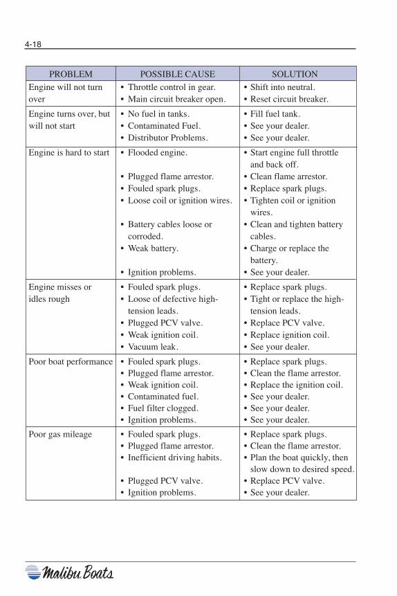
4-18
PROBLEM POSSIBLE CAUSE SOLUTION
Engine will not turn • Throttle control in gear. • Shift into neutral.over • Main circuit breaker open. • Reset circuit breaker.
Engine turns over, but • No fuel in tanks. • Fill fuel tank.will not start • Contaminated Fuel. • See your dealer.
• Distributor Problems. • See your dealer.
Engine is hard to start • Flooded engine. • Start engine full throttle and back off.
• Plugged flame arrestor. • Clean flame arrestor.• Fouled spark plugs. • Replace spark plugs.• Loose coil or ignition wires. • Tighten coil or ignition
wires.• Battery cables loose or • Clean and tighten battery
corroded. cables.• Weak battery. • Charge or replace the
battery.• Ignition problems. • See your dealer.
Engine misses or • Fouled spark plugs. • Replace spark plugs.idles rough • Loose of defective high- • Tight or replace the high-
tension leads. tension leads.• Plugged PCV valve. • Replace PCV valve.• Weak ignition coil. • Replace ignition coil.• Vacuum leak. • See your dealer.
Poor boat performance • Fouled spark plugs. • Replace spark plugs.• Plugged flame arrestor. • Clean the flame arrestor.• Weak ignition coil. • Replace the ignition coil.• Contaminated fuel. • See your dealer.• Fuel filter clogged. • See your dealer.• Ignition problems. • See your dealer.
Poor gas mileage • Fouled spark plugs. • Replace spark plugs.• Plugged flame arrestor. • Clean the flame arrestor.• Inefficient driving habits. • Plan the boat quickly, then
slow down to desired speed.• Plugged PCV valve. • Replace PCV valve.• Ignition problems. • See your dealer.
Chapter 4_10: Chapter 4 doc.qxd 11/3/09 11:41 AM Page 18

4-19
PROBLEM POSSIBLE CAUSE SOLUTION
Throttle/shifting • Corroded cables. • Clean and lubricate cables.problems • Defective throttle return • Replace the throttle return
spring. spring.• Low transmission oil level. • Replenish the transmission
fluid.• Sticking transmission • Clean and lubricate detent
shift detent ball. ball.• Kink in cables. • Replace the cable(s).
See your dealer.
Steering problems • Corroded cables. • Clean and lubricate the cable.
• Rudder worn. • See your dealer.
Excessive vibration. •Damaged propeller. • Replace the propeller.• Misaligned propeller shaft • Check the alignment. See
coupling. your dealer for properrealignment.
• Bent propeller shaft. • See your dealer.
Electrical problems • Open circuit breaker or • Reset the circuit breakerblown fuse. or replace the fuse.
• Loose wing connections • Clean and tighten wiringor corrosion. connections.
• Defective sending unit. • Replace the sending unit.• Shorted wiring harness. • Repair the wiring harness.• Defective switch or gauge. • See your dealer.
No speedometer • Paddle Wheel. • Replace the paddle wheel.• Defective speedometer. • Replace the speedometer.
Incorrect speedometer • Paddle Wheel. • Replace the paddle wheel.• Defective speedometer. • Replace the speedometer.
Chapter 4_10: Chapter 4 doc.qxd 11/3/09 11:41 AM Page 19
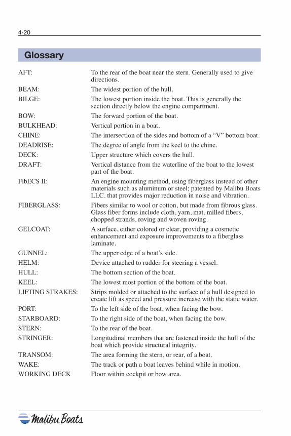
Glossary
AFT: To the rear of the boat near the stern. Generally used to givedirections.
BEAM: The widest portion of the hull.
BILGE: The lowest portion inside the boat. This is generally thesection directly below the engine compartment.
BOW: The forward portion of the boat.
BULKHEAD: Vertical portion in a boat.
CHINE: The intersection of the sides and bottom of a “V” bottom boat.
DEADRISE: The degree of angle from the keel to the chine.
DECK: Upper structure which covers the hull.
DRAFT: Vertical distance from the waterline of the boat to the lowestpart of the boat.
FibECS II: An engine mounting method, using fiberglass instead of othermaterials such as aluminum or steel; patented by Malibu BoatsLLC. that provides major reduction in noise and vibration.
FIBERGLASS: Fibers similar to wool or cotton, but made from fibrous glass.Glass fiber forms include cloth, yarn, mat, milled fibers,chopped strands, roving and woven roving.
GELCOAT: A surface, either colored or clear, providing a cosmeticenhancement and exposure improvements to a fiberglasslaminate.
GUNNEL: The upper edge of a boat’s side.
HELM: Device attached to rudder for steering a vessel.
HULL: The bottom section of the boat.
KEEL: The lowest most portion of the bottom of the boat.
LIFTING STRAKES: Strips molded or attached to the surface of a hull designed tocreate lift as speed and pressure increase with the static water.
PORT: To the left side of the boat, when facing the bow.
STARBOARD: To the right side of the boat, when facing the bow.
STERN: To the rear of the boat.
STRINGER: Longitudinal members that are fastened inside the hull of theboat which provide structural integrity.
TRANSOM: The area forming the stern, or rear, of a boat.
WAKE: The track or path a boat leaves behind while in motion.
WORKING DECK Floor within cockpit or bow area.
4-20
Chapter 4_10: Chapter 4 doc.qxd 11/3/09 11:41 AM Page 20

IndexAAnchoring . . . . . . . . . . . . . . . . . . . . . . . . . 3-16
BBasic Rules of the Road . . . . . . . . . . . . . . 1-10
CCarbon Monoxide . . . . . . . . . . . . . . . . . . . . 1-9Certifications & Standards . . . . . . . . . . . . . . . vCircuit Breakers . . . . . . . . . . . . . . . . . . . . 2-27Corrosion Protection . . . . . . . . . . . . . . . . . 3-19
DDocking . . . . . . . . . . . . . . . . . . . . . . . . . . . 3-13Drain Plugs . . . . . . . . . . . . . . . . . . . . . . . . 2-42Driver’s Seat . . . . . . . . . . . . . . . . . . . . . . . 2-38
EElectrical . . . . . . . . . . . . . . . . . . . . . . . . . . 4-10Emergencies . . . . . . . . . . . . . . . . . . . . . . . . 1-6Emergency Engine Stop Switch . . . . . . . . 2-37Engine / Drive Train . . . . . . . . . . . . . . . . . . 4-5Exhaust . . . . . . . . . . . . . . . . . . . . . . . . . . . 2-44Exterior . . . . . . . . . . . . . . . . . . . . . . . . . . . . 4-3
FFueling. . . . . . . . . . . . . . . . . . . . . . . . . . . . . 3-7Fuel System. . . . . . . . . . . . . . . . . . . . . . . . . 4-9
GGeneral Precautions . . . . . . . . . . . . . . . . . . 1-1Glossary. . . . . . . . . . . . . . . . . . . . . . . . . . . 4-20
HHazardous Conditions . . . . . . . . . . . . . . . . . 1-7High-Speed Operation. . . . . . . . . . . . . . . . 3-14
IIntegral Self Draining Ice Chest . . . . . . . . 2-39Interior. . . . . . . . . . . . . . . . . . . . . . . . . . . . . 4-1Introduction . . . . . . . . . . . . . . . . . . . . . . . . . . v
MMalibu Exclusive Adjustable Rudder
System . . . . . . . . . . . . . . . . . . . . . . . . . . 3-18Miscellaneous . . . . . . . . . . . . . . . . . . . . . . 4-14Model Features & Specifications . . . . . . . . . viiMotorbox Cover . . . . . . . . . . . . . . . . . . . . 2-37
NNavigational Lights. . . . . . . . . . . . . . . . . . 2-41
OOperation by Minors . . . . . . . . . . . . . . . . . 1-10Optional Equipment . . . . . . . . . . . . . . . . . 2-46
PPassenger Safety . . . . . . . . . . . . . . . . . . . . 1-10 Power Wedge . . . . . . . . . . . . . . . . . . . . . . 2-22Propellers. . . . . . . . . . . . . . . . . . . . . . . . . . 3-17
RRegulations . . . . . . . . . . . . . . . . . . . . . . . . . 1-3Responsibilities . . . . . . . . . . . . . . . . . . . . . . 1-3
SSafety Statements . . . . . . . . . . . . . . . . . . . . 1-1Shifting / Running . . . . . . . . . . . . . . . . . . . 3-10Ski Pylon . . . . . . . . . . . . . . . . . . . . . . . . . . 2-39Speedometer Pickup . . . . . . . . . . . . . . . . . 2-43Standard Gauges . . . . . . . . . . . . . . . . . . . . . 2-1Starting . . . . . . . . . . . . . . . . . . . . . . . . . . . . 3-8Steering . . . . . . . . . . . . . . . . . . . . . . . . . . . 3-10Steering System. . . . . . . . . . . . . . . . . . . . . 2-37Stopping . . . . . . . . . . . . . . . . . . . . . . . . . . 3-12Storage Areas . . . . . . . . . . . . . . . . . . . . . . 2-41Sundeck . . . . . . . . . . . . . . . . . . . . . . . . . . . 2-39Swim Platform . . . . . . . . . . . . . . . . . . . . . 2-40Switches & Indicators . . . . . . . . . . . . . . . . 2-27
TThrottle Control. . . . . . . . . . . . . . . . . . . . . 2-36Tilt Steering Wheel . . . . . . . . . . . . . . . . . . 2-43Towing a Skier . . . . . . . . . . . . . . . . . . . . . 3-14Towing Another Boat . . . . . . . . . . . . . . . . 3-16Trailering. . . . . . . . . . . . . . . . . . . . . . . . . . . 3-1Troubleshooting . . . . . . . . . . . . . . . . . . . . 4-17
VV-Drive Engine Access Hatch . . . . . . . . . 2-39Ventilation. . . . . . . . . . . . . . . . . . . . . . . . . 2-45
WWarning Labels . . . . . . . . . . . . . . . . . . . . . . 3-4Wedge . . . . . . . . . . . . . . . . . . . . . . . . . . . . 2-57
4-21
Chapter 4_10: Chapter 4 doc.qxd 11/5/09 10:39 AM Page 21
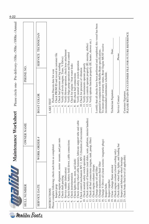
INST
RU
CT
ION
SPl
ease
com
plet
e fo
llow
ing;
che
ck e
ach
item
as
com
plet
ed.
____
1.
Insp
ect p
rop
____
2.
Che
ck e
ngin
e al
ignm
ent,
mot
or m
ount
s, a
nd ja
m n
uts
____
3.
Che
ck s
haft
pac
king
____
4.
Serv
ice
rudd
er (
lubr
icat
ion)
____
5.
Che
ck b
atte
ry, b
atte
ry h
old
dow
n, c
able
con
nect
ions
____
6.
Che
ck in
stru
men
tatio
n__
__ 7
.C
heck
ligh
ts (
bow
, ste
rn, a
nd d
ash)
____
8.
Che
ck s
teer
ing
whe
el c
able
fas
tene
rs, l
ubri
cate
sup
port
tube
and
cab
le__
__ 9
. C
heck
con
trol
mec
hani
sm M
V-2
, MV
-3 (
free
dom
of
mov
emen
t)__
__ 1
0. C
heck
neu
tral
saf
ety
switc
h op
erat
ion
____
11.
Che
ck s
ecur
ity o
f fa
sten
ers
(sea
t slid
es, s
eats
, pla
tfor
m, i
nter
ior
hand
les)
____
12.
Che
ck a
ll fu
el c
onne
ctio
ns (
engi
ne, t
ank,
pum
p, f
ilter
)__
__ 1
3. C
heck
eng
ine
exha
ust c
lam
ps__
__ 1
4. C
hang
e en
gine
oil
and
filte
r__
__ 1
5. C
hang
e tr
ansm
issi
on f
luid
/ filt
er__
__ 1
6. C
hang
e V
-Dri
ve o
il (c
lean
scr
eens
/ m
agne
tic p
lugs
)__
__ 1
7. I
nspe
ct b
elts
____
18.
Ins
pect
impe
ller
____
19.
Cle
an /
chan
ge f
lam
e ar
rest
or__
__ 2
0. C
heck
eng
ine
cool
ant (
clos
ed c
oolin
g on
ly)
____
21.
Che
ck tr
aile
r: w
heel
lugs
, lig
hts,
and
load
ing
bar
____
22.
Ins
pect
and
lubr
icat
e w
heel
bea
ring
s__
__ 2
3. C
heck
bra
ke f
luid
leve
l (if
app
licab
le)
LA
KE
TE
ST__
__ 1
.Pe
rfor
m D
iaco
m d
ata
list s
can
____
2.
Che
ck P
RO
M I
D a
nd r
ecor
d in
cus
tom
er f
ile__
__ 3
.C
heck
fue
l pre
ssur
e an
d lo
g re
adin
g__
__ 4
.V
erif
y oi
l lev
els
(eng
ine,
Tra
ns, V
-Dri
ve)
____
5.
Ver
ify
blow
er o
pera
tion,
che
ck h
ose
atta
chm
ent
____
6.
Ver
ify
bilg
e pu
mp
oper
atio
n an
d fl
oat c
ontr
ol__
__ 7
.C
heck
for
eng
ine
/ boa
t wat
er le
aks
____
8.
RE
-che
ck f
uel c
onne
ctio
ns
____
9.
Ver
ify
neut
ral s
afet
y sw
itch
oper
atio
n__
__ 1
0.C
heck
for
pre
senc
e of
vib
ratio
n__
__ 1
1.V
erif
y in
stru
men
ts o
pera
te p
rope
rly
____
12.
Ver
ify
cont
rols
ope
rate
pro
perl
y (I
E; s
teer
ing,
shi
fter
)__
__ 1
3.V
erif
y op
tions
fun
ctio
n pr
oper
ly (
IE; h
eate
r, s
how
er e
tc.)
I ce
rtif
y th
at a
ll ch
ecks
hav
e be
en p
erfo
rmed
and
com
plet
ed, t
his
vess
el h
as b
een
prep
ared
in c
onju
nctio
n w
ith M
alib
u B
oats
spe
cifi
catio
ns.
To
ensu
re p
rope
r w
arra
nty
stat
us, B
oat/
Eng
ine
MU
ST r
ecei
ve
reco
mm
ende
d m
aint
enan
ce s
ched
ule.
Tec
hnic
ian
Sign
atur
e___
____
____
____
____
____
__ D
ate_
____
___
Serv
ice
Con
tact
___
____
____
____
____
____
__Ph
one_
____
____
___
Cus
tom
er S
igna
ture
____
____
____
____
____
____
____
____
____
___
PLE
ASE
RE
TA
IN I
N C
UST
OM
ER
FIL
E F
OR
FU
TU
RE
RE
FER
EN
CE
Mai
nten
ance
Wor
kshe
et
Ple
ase
circ
le o
ne-
Pre
-del
iver
y-/1
0hr.-
/50h
r.-/1
00hr
.-/A
nnua
l
HU
LL
NU
MB
ER
OW
NE
R N
AM
EPH
ON
E N
O.
SER
VIC
E D
AT
EW
OR
K O
RD
ER
#B
OA
T C
OL
OR
SER
VIC
E T
EC
HN
ICIA
N
4-22
Chapter 4_10: Chapter 4 doc.qxd 11/3/09 11:41 AM Page 22
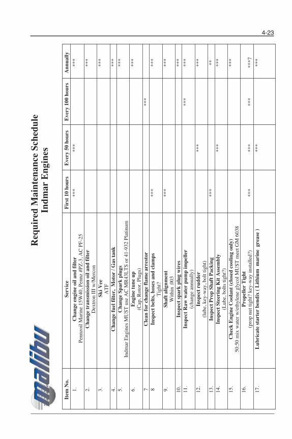
Item
No.
Serv
ice
Fir
st 1
0 ho
urs
Eve
ry 5
0 ho
urs
Eve
ry 1
00 h
ours
Ann
ually
1.C
hang
e en
gine
oil
and
filt
er**
***
***
*Pe
nnzo
il M
arin
e 15
W40
, Pen
nz #
PZ-3
, AC
PF-
252.
Cha
nge
tran
smis
sion
oil
and
filt
er**
*D
extr
on I
II w
/Mer
con
3.Sk
i Vee
**
*A
TF
4.C
hang
e fu
el f
ilter
, M
otor
/ G
as t
ank
***
5.C
hang
e Sp
ark
plug
s**
*In
dmar
Eng
ines
MU
ST u
se A
C M
R43
LT
S or
41-
932
Plat
inum
6.E
ngin
e tu
ne u
p**
*(C
ap, R
otor
, Plu
gs)
7C
lean
for
cha
nge
flam
e ar
rest
or**
*8
Insp
ect
belt
s, h
oses
and
cla
mps
***
***
Tig
ht?
9.Sh
aft
alig
nmen
t**
***
*W
ithin
.003
10.
Insp
ect
spar
k pl
ug w
ires
***
11.
Insp
ect
Raw
wat
er p
ump
impe
ller
***
***
(cha
nge
annu
ally
)12
.In
spec
t ru
dder
***
***
(lub
e, k
ey-w
ay, b
olt t
ight
)13
.In
spec
t P
rop
Shaf
t P
acki
ng**
***
14.
Insp
ect
Stee
ring
Kit
Ass
embl
y**
***
*(L
ube,
bol
ts ti
ght?
)15
.C
heck
Eng
ine
Coo
lant
(cl
osed
coo
ling
only
)**
*50
:50
mix
wat
er w
/eth
ylen
e gl
ycol
MU
ST m
eet G
M 6
038
16.
Pro
pelle
r T
ight
(pro
p nu
t tig
ht?
key-
way
inst
alle
d?)
***
***
***
***7
17.
Lub
rica
te s
tart
er b
endi
x (
Lit
hium
mar
ine
gre
ase
)**
***
*
Req
uire
d M
aint
enan
ce S
ched
ule
Indm
ar E
ngin
es4-23
Chapter 4_10: Chapter 4 doc.qxd 11/3/09 11:41 AM Page 23

4-24
Notes
Chapter 4_10: Chapter 4 doc.qxd 11/3/09 11:41 AM Page 24

2010 MALIBU BOATS LIMITEDWARRANTY
Your Legal Rights Under These Limited Warranties:
The warranties contained in this booklet are the only expressed warranties that MalibuBoats, LLC (“Malibu Boats”) makes for your boat. These warranties give you specificlegal rights. You may also have other rights that vary from state to state. Forexample, you may have some implied warranties, depending on the state where your boatis registered:
• An “implied warranty of merchantability” means that your boat is reasonably fit forthe general purpose for which it was sold.
• An “implied warranty of fitness for a particular purpose” means that your boat issuitable for your special purposes if those special purposes were specifically disclosedto Malibu Boats itself – not merely to the dealer – before your purchase, and MalibuBoats – not just the dealer - told you the boat would be suitable for that purpose.
ANY IMPLIED WARRANTIES, INCLUDING IMPLIED WARRANTIES OFMERCHANTABILITY AND FITNESS, ARE LIMITED IN DURATION TO THEWARRANTY PERIOD. INCIDENTAL AND CONSEQUENTIAL DAMAGESARE EXCLUDED FROM COVERAGE UNDER THIS LIMITED WARRANTY.SOME STATES DO NOT ALLOW THE EXCLUSION OF INCIDENTAL ORCONSEQUENTIAL DAMAGES AND THE LIMITATION ON HOW LONG ANIMPLIED WARRANTY LASTS, SO THE ABOVE LIMITATIONS ANDEXCLUSIONS MAY NOT APPLY TO YOU. THIS WARRANTY GIVES YOUSPECIFIC LEGAL RIGHTS, AND YOU MAY ALSO HAVE OTHER RIGHTSWHICH VARY FROM STATE TO STATE.
Who Is CoveredThe 2010 Malibu Boats Limited Warranty is provided to the original owner(s) of aMalibu boat originally distributed by Malibu Boats and originally sold by an authorizedMalibu Boats dealership.
In cases of resale, any remaining warranties may be transferred to a subsequent ownerpursuant to the terms and conditions set forth in the section “Warranty Transfer Option.”
A warranty registration card is supplied with every new Malibu boat. Malibu Boatshighly encourages owners to complete this card at the time of sale. Doing so ensuresMalibu Boats is able to keep owners informed of important safety and serviceinformation.
IMPORT EXCLUSION:
Boats manufactured in the USA by Malibu Boats LLC and imported into Australia and/orNew Zealand are void of any warranties outlined in this book.
Warranty_10_Malibu: Chapter 4 doc.qxd 11/3/09 11:46 AM Page 1

W-2
What Is Covered Under Your Malibu Limited Warranty:
Basic Limited Boat WarrantyWhat is covered:a. The Basic Limited Boat Warranty covers all parts and labor needed to repair
defective items or components on your boat supplied by Malibu Boats that aredefective in material, workmanship or factory preparation.
b. This warranty applies to all items or components except for the exclusions or itemslisted under the caption “What Is Not Covered,” or as indicated below.
When it begins: The Basic Limited Boat Warranty begins on either of the followingdates, whichever is earlier:a. The date you take delivery of the boat; or b. The date the boat was first put into service – for example, as a dealer “demo” or as a
Malibu Boats factory “demo.”
When it ends:a. The Basic Limited Boat Warranty extends to the original owner and lasts for 36
months from the date it begins.b. See “Warranty Transfer Option.”
Lifetime Limited Hull Warranty
What is covered:a. The Lifetime Limited Hull Warranty covers the cost of all parts and labor needed to
repair any hull, deck, liner, stringer or upholstery frame supplied by Malibu Boatsthat is structurally defective in material or workmanship.
b. These warranty repairs or adjustments may be made by your dealer or Malibu Boatsusing new or remanufactured parts.
c. Malibu Boats, or its authorized dealer, will repair or replace, at Malibu’s option, anyboat or portion thereof proven to its satisfaction to be defective during its warrantyperiod.
Exception: The Lifetime Limited Hull Warranty does not cover the gelcoat or anyother components fastened or applied to the dash, hull or deck. Gelcoat discoloration,blisters and cracks are not considered structural defects. Gelcoat, along with installedcomponents, are warranted separately under Malibu’s “Basic Limited BoatWarranty” and “Gelcoat Limited Warranty” listed on the following page.
When it begins: The Lifetime Limited Hull Warranty begins at the end of the BasicLimited Boat Warranty on the date your boat has been in service for more than 36 months.
When it ends:a. The Lifetime Limited Hull Warranty extends to the original owner for as long as they
own the boat. The warranty, unless transferred, is terminated upon the boat’s sale ortransfer of ownership.
b. See “Warranty Transfer Option.”
Warranty_10_Malibu: Chapter 4 doc.qxd 11/3/09 11:46 AM Page 2
W-3
Gelcoat Limited Warranty What is covered:The Gelcoat Limited Warranty covers all parts and labor needed to repair or correct thegelcoat finish of your new boat supplied by Malibu Boats that are a result of defects inmaterial or workmanship.
This warranty is contingent only upon the understanding that the boat will be regularlywashed using a mild detergent or other appropriate cleaning compound. In addition,when the boat is not in use, it is to be stored out of the water by one of the followingmethods:
• Out of the water on a trailer with a canvas or similar cover;• Out of the water under a covered dry dock or hydrohoist; or• Out of the water in a garage or other structure with four walls and a roof.
Exceptions to this warranty are listed under the caption “What Is Not Covered.”
When it begins: The Gelcoat Limited Warranty begins on either of the following dates,whichever is earlier:a. The date you take delivery of the boat; orb. The date the boat was first put into service – for example, as a dealer “demo” or as a
Malibu Boats factory “demo.”
When it ends:a. The Gelcoat Limited Warranty extends to the original owner and lasts for 24 months
from the date it begins.b. See “Warranty Transfer Option.”
Powertrain Limited Warranty
What is covered:a. Indmar Powertrains
• Indmar Products Company, Inc. maintains its own warranty, independent fromMalibu Boats. However, to improve the level of service to our dealers andcustomers, Malibu Boats administers the engine warranty on units equipped withan Indmar powertrain on Indmar’s behalf.
• Please refer to your Indmar Engine Owner’s Manual for specific warrantycoverage information.
When it begins: The Powertrain Limited Boat Warranty begins on either of the followingdates, whichever is earlier:• The date you take delivery of the boat; or• The date the boat was first put into service – for example, as a dealer “demo” or as a
Malibu Boats factory “demo.”
When it ends:a. Indmar Powertrains
• The powertrain coverage for Indmar-equipped units lasts for 36 months from thedate it begins without any hour limitation.
• See “Warranty Transfer Option.”
Warranty_10_Malibu: Chapter 4 doc.qxd 11/3/09 11:46 AM Page 3
W-4
Audio System Limited Warranty
What is covered:a. The Audio System Limited Warranty covers all parts and labor needed to repair
defective audio system items or components on your boat supplied by Malibu Boatsthat are defective in material or workmanship.
b. This warranty applies to all audio system items or components, except for theexclusions or items listed under the caption “What Is Not Covered” or as indicatedbelow.
When it begins: The Audio System Limited Warranty begins on either of the followingdates, whichever is earlier:a. The date you take delivery of the boat; orb. The date the boat was first put into service – for example, as a dealer “demo” or as a
Malibu Boats factory “demo.”
When it ends:a. The Audio System Limited Warranty extends to the original owner and lasts for 36
months from the date it begins.b. See “Warranty Transfer Option.”
Basic Tower Warranty
What is covered:a. The Basic Tower Warranty covers all parts and labor needed to repair defective items
or components of your tower supplied by Malibu Boats that are defective in material,workmanship or factory preparation.
b. This warranty applies to structural integrity of the tower components except for theexclusions or items listed under that caption “What Is Not Covered,” or as indicatedbelow.
c. Covered items found to be structurally damaged or weakened within the warrantyperiod will be repaired or replaced at Malibu’s discretion.
d. This warranty does not extend to surface coating of the tower, tower accessories orcosmetic finishes of the tower or tower accessories (see below).
When it begins: The Basic Tower Warranty begins on either of the following dates,whichever is earlier:a. The date you take delivery of the boat; orb. The date the boat was first put into service – for example, as a dealer “demo” or as a
Malibu Boats factory “demo.”
When it ends:a. The Basic Tower Warranty extends to the original owner and lasts for 36 months
from the date it begins.b. Surface coating of the tower, tower accessories or cosmetic finishes of the tower or
tower accessories extends to the original owner only and lasts for 12 months fromthe date it begins.
c. See “Warranty Transfer Option.”
Warranty_10_Malibu: Chapter 4 doc.qxd 11/3/09 11:46 AM Page 4

Warranty Transfer OptionA transfer fee of five hundred dollars ($500.00) payable to Malibu Boats LLC. willinclude the Limited Lifetime Hull Warranty and remaining three (3) year bumper tobumper engine warranty supplied by Indmar Products for a period of three (3) yearsfrom:a. The date the boat was originally delivered to the first owner; orb. The date the boat was first put into service - for example, as a dealer “demo” or as a
Malibu factory “demo.”
All remaining warranties may be transferred, subject to a boat inspection fee to bedetermined by an authorized Malibu Boats Dealer. Contact your nearest MalibuBoat Dealer for transfer details, including applicable fees and the scheduling of aboat inspection.
Any warranty transferred pursuant to this section does not extend the length of thewarranties as specifically limited by the section “What Is Covered Under YourMalibu Limited Warranty.”
Operation RequirementsYour Owner’s Manual contains important operation and maintenance requirements thatyou must follow to maintain warranty coverage for your boat. Please carefully reviewand follow these requirements.
W-5
Warranty_10_Malibu: Chapter 4 doc.qxd 11/3/09 11:46 AM Page 5
What Is Not Covered:
Modifications Not Covered:
Some Modifications Do Not Void the Warranties But Aren’t CoveredCertain modifications that you make to your boat do not, by themselves, void thewarranties described in this booklet. Examples include:a. Installing non-Malibu approved parts, components or equipment (such as towers,
speed control equipment, aftermarket stereo equipment); andb. Using special non-Malibu or Indmar approved materials or additives.
But your warranties do not cover any part that Malibu Boats did not supply or is notcertified for use on your boat. Nor do your warranties cover the costs of any repairs oradjustments that may be caused or needed because of the installation or use of non-Malibu approved parts, components, equipment, materials or additives.
Examples of alterations that are not covered include: • Towers • Tower accessories (lights, speakers, etc.)• Aftermarket Ballast Systems• Barefoot booms• Canvas accessories• Bottom painting• Improper repairs
Modifications That WILL Void Your WarrantiesThe following modifications will void your warranties:a. Overloading or overpowering your boat;b. Disconnecting, tampering with, or altering the boat’s hour meter, unless your
repairing technician follows the legal requirements for repairing or replacing hourmeters;
c. Attaching any device that disconnects the hour meter; ord. Tampering with or disabling any factory warning device or system.e. Tampering with the wiring harnesses or fuel system.
Environmental Factors Not CoveredYour warranties do not cover damage caused by environmental factors such as airbornefallout, chemicals, tree sap, salt, ocean spray, mold, acid rain, road and boating hazards.Nor do your warranties cover damage caused by hailstorms, windstorms, tornados,sandstorms, lightning, floods, earthquakes or any other acts of God.
Your warranties do not cover conditions resulting from anything impacting the boat. Thisincludes cracks, chips and scratches in the gelcoat finish, windshield glass, paintedsurfaces or damage from collision.
W-6
Warranty_10_Malibu: Chapter 4 doc.qxd 11/3/09 11:46 AM Page 6
Maintenance Costs Not Covered Your warranties do not cover the costs of repairing damage caused by poor or impropermaintenance. Nor do they cover damage caused by use of contaminated fuels or by the useof oils, lubricants, cleaners or fluids other than those recommended in your Owner’s Manual.
Your warranties do not cover the costs of your boat’s normal or scheduled maintenance –the parts and services that all boats routinely need. Some of these parts and services,which your warranties do not cover, include:• Inspections• Lubrication• Engine tune-ups• Replacing filters, coolants, spark plugs, bulbs, or fuses (unless those costs result from
a covered repair)• Sea water impellers• Propshaft packing• Cleaning and polishing• Replacing non-LED lightbulbs
Gelcoat ExclusionsMalibu Boats prides itself on the quality and craftsmanship we put into every boat. Thegelcoat finish on all Malibu boats is applied by hand. Therefore, very minor finishdistortions or imperfections may be found in areas of the boat, e.g., along the boat’s pinstriping. Such minor imperfections are considered normal in a handcrafted product andare not considered warrantable.
Warranty consideration for chalk and fade only applies to gelcoat applied above the water line.
Corrosion ExclusionsYour warranties do not cover the following:• Surface corrosion caused by such things as salt, salt spray, sand and road debris.• Corrosion caused by accident, damage, abuse or boat alteration.• Pitting or oxidation• Electrolysis (galvanic corrosion)
Tower ExclusionsThe Basic Tower Warranty does not extend to aftermarket towers or accessories that areinstalled by anyone other than Malibu Boats.
Inappropriate usage of the tower for activities not included in the Owner’s manual mayresult in damage not coverable by the warranty.
Incidental and Consequential Damages Not CoveredYour warranties do not cover any incidental or consequential damages.
Examples of such damages include:• Lost time• Inconvenience• The loss of use of your boat• The cost of a rental boat, gasoline, telephone, travel or lodging• The loss of personal or commercial property
W-7
Warranty_10_Malibu: Chapter 4 doc.qxd 11/3/09 11:46 AM Page 7
• The loss of revenue• Transportation costs to/from dealership• Or any other incidental or consequential damages
Performance characteristics, such as speed, acceleration, fuel consumption, etc., as theyare estimated and can vary under numerous conditions.
Some states do not allow incidental or consequential damages to be excluded or limited,so this exclusion may not apply to you.
Other ExclusionsYour warranties do not cover the costs of repairing damage or conditions caused by anyof the following:• Overloading or overpowering • Fire or accident• Abuse or neglect• Misuse (proper use is outlined in your Owner’s Manual)• Windshield damage from external objects• Water damage to items in the glove box• Any changes or modifications made to your boat that do not comply with Malibu
Boats’ specifications• Using any fluid that does not meet the minimum specifications in the Owner’s Manual
If you use your boat primarily for business or commercial purposes, then these impliedwarranties do not apply and Malibu Boats, LLC completely disclaims them to the extentallowed by law. The implied warranty of fitness for a particular purpose does not apply ifyour boat is used for exhibition, even if the boat is equipped for that purpose.
Total Loss, Salvage, Junk or Scrap Boats Not CoveredA boat has no warranty of any kind if:a. The boat is declared to be a total loss by an insurance company; orb. The boat is rebuilt after being declared to be a total loss by an insurance company.
Malibu Boats will deny warranty coverage without notice if it learns that a boat isineligible for coverage for any of these reasons.
Items Covered By Other WarrantiesThe following items are covered by separate warranties offered by their manufacturers ordistributors. They are not covered by the Basic Limited Warranty:• Trailers• Tires• Items added or changed after the boat left Malibu Boats’ manufacturing plant, such as
accessories or protection products, or items changed because of customization.
Be sure you get a copy of any warranty that applies to these items from your dealer, orfrom the manufacturer of the product.
Restricted WarrantyYour warranties can also be restricted by Malibu Boats if the boat is not properlymaintained, or if the boat is overloaded, abused or neglected and the overloading, abuseor neglect interferes with the proper functioning of the boat. If the warranty is restricted,coverage may be denied or subject to approval by Malibu Boats before covered repairsare performed.
W-8
Warranty_10_Malibu: Chapter 4 doc.qxd 11/12/09 4:27 PM Page 8

Other Terms of Your Warranties:
Exchanged Parts May Be Used in Warranty RepairsIn the interest of customer satisfaction, Malibu Boats may offer exchange service onsome boat parts. This service is intended to reduce the amount of time your boat is notavailable for your use because of repairs. Parts used in exchange service may be new,remanufactured, reconditioned or repaired, depending on the part involved.
All exchange parts meet Malibu Boats’ standards and have the same warranties as new parts.
Examples of the type of exchange parts that may be used include:• Engine assemblies• Transmission and V-Drive assemblies• Instrumentation • “Wedge” parts or assemblies • Audio equipment
Replacement PartsIf an exact replacement is no longer available, or if a superior substitute is available, wemay install a part that has similar or greater overall performance at our option.Replacement parts are only warranted for the remainder of the original warranty period.
Pre-Delivery ServiceA defect or damage to the finish, mechanical, electrical, interior or other components ofyour boat may have occurred at the factory or while it was being shipped to your dealer.
Such a defect or damage is usually detected and corrected while at the factory. Inaddition, dealers must inspect each boat before delivery. They repair any defects ordamage detected before the boat is delivered to you.
Production ChangesMalibu Boats and its dealers reserve the right to make changes in boats built or sold bythem at any time without incurring any obligation to make the same or similar changes onboats previously built or sold.
Governing Law and Other TermsAll of the warranties maintained by Malibu Boats are made under California Law, andCalifornia Law will be used to interpret them. Except to the extent allowed by law,punitive, exemplary or multiple damages may not be recovered. No person, includingMalibu Boats’ employees or its dealers, may modify or waive any part of thesewarranties.
This warranty gives you specific legal rights and you may also have other rights, whichvary from state to state.
If you purchased, registered or operate your boat in another Country other than theUnited States, e.g., the European Union, you may have legal rights under applicableinternational legislation governing the sale of consumer goods which are not affected bythese warranties.
IMPORT EXCLUSION:Boats manufactured in the USA by Malibu Boats LLC and imported into Australia and/orNew Zealand are void of any warranties outlined in this book.
W-9
Warranty_10_Malibu: Chapter 4 doc.qxd 11/12/09 4:29 PM Page 9
How to Get Warranty Service:
Your ResponsibilitiesFor a covered repair to be given warranty consideration, it is your responsibility to notifyan authorized Malibu Boats dealer of the non-conformity within thirty (30) days of itsoccurrence or failure.
Where to Take Your BoatWarranty service must be performed by an authorized Malibu Boats dealer. We stronglyrecommend that you take your boat to your selling dealership. They know you and yourboat best, and are most concerned that you get prompt and high quality service. If youmove, warranty service may be requested from any authorized Malibu Boats dealer.
Emergency Warranty RepairsIf you are out of your local area on vacation, have an emergency that may be coveredunder this warranty, and have to have repairs made by someone other than an authorizedMalibu Boats dealer, please follow this procedure:a. Please get a detailed receipt for the work done. Make sure this receipt lists all the
repairs and parts that were involved. b. When you return home, contact Malibu Boats’ Customer Service/Warranty
Department (“Helpful Addresses and Telephone Numbers”) to discuss your claimand possible reimbursement consideration. You will normally need to provide acopy of the receipt, your boat’s hull identification number and any other relevantdocuments.
The Emergency Warranty Repairs clause does not apply to boats built in Australia. Foremergency assistance in this region, contact your Malibu dealer.
How to Deal with Warranty Problems
Steps to TakeIn General:Normally, your dealer’s sales or service departments can resolve warranty problems.That is why you should always talk to your dealer’s service manager or sales managerfirst. But if you are not satisfied with your dealer’s response to your problem, MalibuBoats recommends that you do the following:
Step 1: Discuss your problem with the owner or general manager of the dealership.
Step 2: If your dealership still cannot resolve the issue, contact Malibu Boats’ CustomerService Department (“Helpful Addresses and Telephone Numbers”).
What Malibu Boats Will DoOnce you have followed the two steps described above, a Malibu Boats representative atMalibu Boats’ Headquarters will review your situation. If it is something that MalibuBoats can help you with, Malibu will provide your dealer with all the information andassistance necessary to resolve the problem. Even if Malibu Boats cannot help you,Malibu will acknowledge your contact and explain Malibu’s position.
W-10
Warranty_10_Malibu: Chapter 4 doc.qxd 11/3/09 11:46 AM Page 10
Notice Under State Lemon LawsSome states have laws allowing you to request a replacement boat or refund of the boat’spurchase price under certain circumstances. These laws vary from state to state. If yourstate allows, Malibu Boats requires that you first notify us in writing of any servicedifficulty that you may have experienced so that we are given a reasonable opportunity tomake any needed repairs before you are eligible for remedies provided by these laws. Inall other states, we ask that you give us written notice of any service difficulty. Send yourwritten notice to Malibu Boats Customer Service Department at the address in “HelpfulAddresses and Telephone Numbers.”
Helpful Information:Here is the address and telephone number of Malibu Boats’ customer service departmentthat can help you wherever you happen to be.
Malibu Boats Customer Service/Warranty Department:
One Malibu CourtMerced, CA 95340(209) 383-7469
Australia and New Zealand:
Malibu Boats Pty Ltd813 Hope CourtAlbury, NSW 2640+61 2 6040 1174
W-11
Warranty_10_Malibu: Chapter 4 doc.qxd 11/16/09 2:14 PM Page 11

NotesW-12
Warranty_10_Malibu: Chapter 4 doc.qxd 11/3/09 11:46 AM Page 12