trade register no. 17150044, vat no. nl8112.30.946.b01 ... · ccs inc. high performance and with...
TRANSCRIPT
CCS Inc.
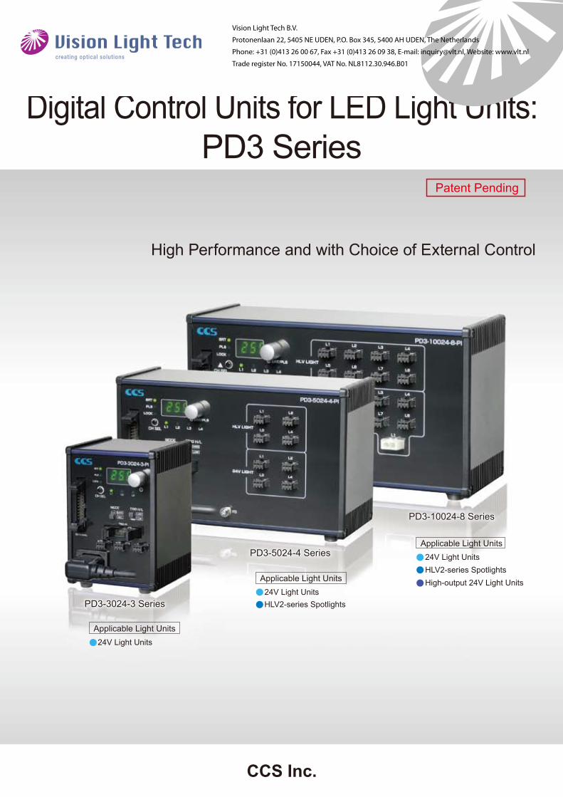
High Performance and with Choice of External Control
PD3-3024-3 SeriesPD3-3024-3 Series
PD3-5024-4 SeriesPD3-5024-4 Series
PD3-10024-8 SeriesPD3-10024-8 Series
Digital Control Units for LED Light Units:PD3 Series
Patent Pending
24V Light Units
24V Light Units
24V Light Units
Applicable Light Units
Applicable Light Units
Applicable Light Units
HLV2-series Spotlights
HLV2-series SpotlightsHigh-output 24V Light Units
Vision Light Tech B.V.
Protonenlaan 22, 5405 NE UDEN, P.O. Box 345, 5400 AH UDEN, The Netherlands
Phone: +31 (0)413 26 00 67, Fax +31 (0)413 26 09 38, E-mail: [email protected], Website: www.vlt.nl
Trade register No. 17150044, VAT No. NL8112.30.946.B01
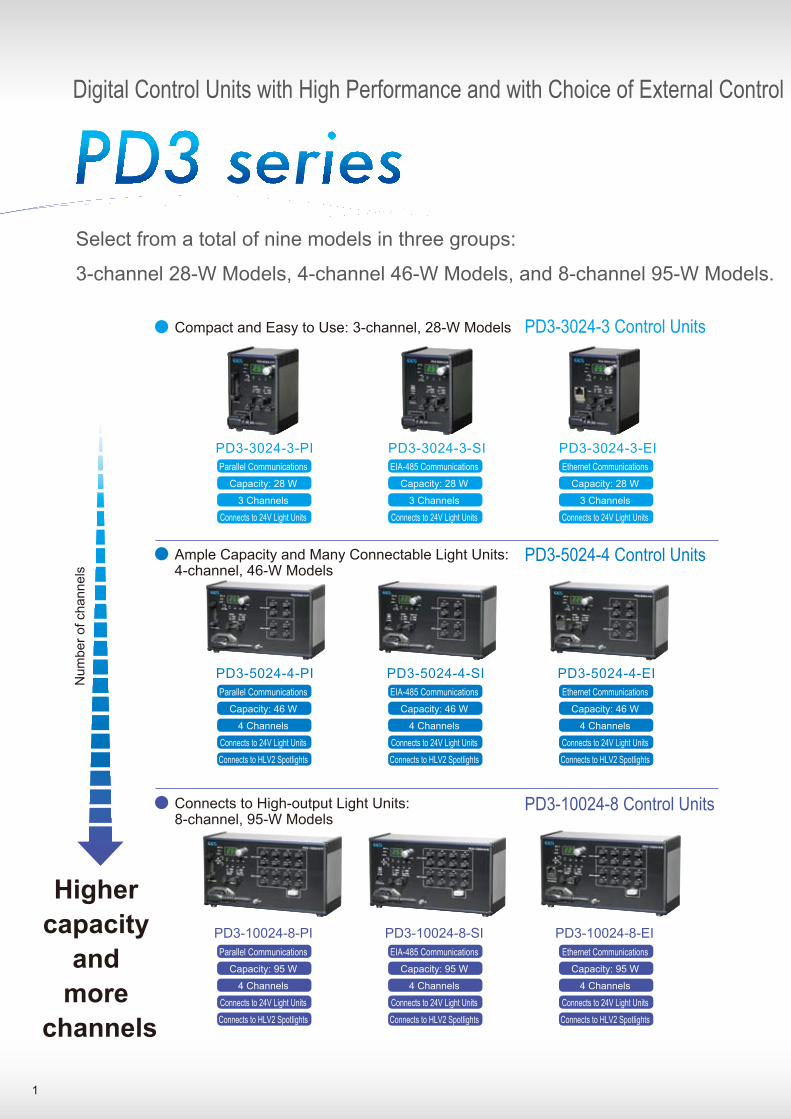
Digital Control Units with High Performance and with Choice of External Control
Select from a total of nine models in three groups:
3-channel 28-W Models, 4-channel 46-W Models, and 8-channel 95-W Models.
Higher
capacity
and
more
channels
PD3-5024-4-PI PD3-5024-4-SI PD3-5024-4-EI
PD3-3024-3-PI PD3-3024-3-SI PD3-3024-3-EI
PD3-10024-8-PI PD3-10024-8-EIPD3-10024-8-SI
Num
ber o
f cha
nnel
s
Compact and Easy to Use: 3-channel, 28-W Models PD3-3024-3 Control Units
Ample Capacity and Many Connectable Light Units: 4-channel, 46-W Models
PD3-5024-4 Control Units
Connects to High-output Light Units: 8-channel, 95-W Models
Ethernet Communications
Capacity: 28 W
3 Channels
Connects to 24V Light Units
EIA-485 Communications
Capacity: 28 W
3 Channels
Connects to 24V Light Units
Parallel Communications
Capacity: 28 W
3 Channels
Connects to 24V Light Units
Parallel Communications
Capacity: 46 W
4 Channels
Connects to 24V Light Units
Connects to HLV2 Spotlights
Parallel Communications
Capacity: 95 W
4 Channels
Connects to 24V Light Units
Connects to HLV2 Spotlights
EIA-485 Communications
Capacity: 46 W
4 Channels
Connects to 24V Light Units
Connects to HLV2 Spotlights
EIA-485 Communications
Capacity: 95 W
4 Channels
Connects to 24V Light Units
Connects to HLV2 Spotlights
Ethernet Communications
Capacity: 46 W
4 Channels
Connects to 24V Light Units
Connects to HLV2 Spotlights
Ethernet Communications
Capacity: 95 W
4 Channels
Connects to 24V Light Units
Connects to HLV2 Spotlights
1
PD3-10024-8 Control Units
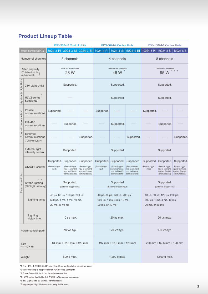
Number of channels
Rated capacity
3024-3-PI 3024-3-SI 3024-3-EI 5024-4-PI 5024-4-SI 5024-4-EI 10024-8-PI 10024-8-SI 10024-8-EI
(TCP/IP or UDP/IP)
(24V Light Units only)
Parallel communications
EIA-485 communications
Ethernet communications
External light intensity control
Lighting times
Power consumption
Size
Weight
24V Light Units
HLV2-series Spotlights
Total output for all channels
*1 The HLV-14-R/-SW/-BL/GR and HLV-27-series Spotlights cannot be used.
*2 Strobe lighting is not possible for HLV2-series Spotlights.
*3 These Control Units do not include an overdrive.
*4 HLV2-series Spotlights: 3.9 W (700 mA) max. per connector.
*5 24V Light Units: 60 W max. per connector.
*6 High-output Light Unit connector only: 95 W max.
*1
*4 *4 *5 *6
*2 *3
App
licab
le L
ight
Uni
tsE
xter
nal c
ontro
l met
hod
Ext
erna
l con
trols
ON/OFF control
Strobe lighting
Lighting delay time
(W × D × H)
95 WTotal for all channels
46 WTotal for all channels
28 WTotal for all channels
(External trigger input)
3 channels
(External trigger input or command input via EIA-485 communications)
(External trigger input)
40 µs, 80 µs, 120 µs, 200 µs,
600 µs, 1 ms, 4 ms, 10 ms,
20 ms, or 40 ms
40 µs, 80 µs, 120 µs, 200 µs,
600 µs, 1 ms, 4 ms, 10 ms,
20 ms, or 40 ms
40 µs, 80 µs, 120 µs, 200 µs,
600 µs, 1 ms, 4 ms, 10 ms,
20 ms, or 40 ms
600 g max.
78 VA typ.
10 µs max.
84 mm × 82.6 mm × 120 mm
(External trigger input or command input via Ethernet communications)
4 channels
(External trigger input)
1,200 g max.
70 VA typ.
20 µs max.
197 mm × 82.6 mm × 120 mm
8 channels
(External trigger input)
1,500 g max.
130 VA typ.
20 µs max.
220 mm × 82.6 mm × 120 mm
Product Lineup Table
Model numbers (PD3-)
PD3-3024-3 Control Units PD3-5024-4 Control Units PD3-10024-8 Control Units
2
(External trigger input)
(External trigger input or command input via EIA-485 communications)
(External trigger input or command input via Ethernet communications)
(External trigger input)
(External trigger input or command input via EIA-485 communications)
(External trigger input or command input via Ethernet communications)
Supported. Supported. Supported.
Supported. Supported.
Supported. Supported. Supported.
Supported. Supported. Supported.
Supported. Supported. Supported.
Supported. Supported. Supported.
Supported. Supported. Supported.Supported. Supported. Supported.Supported. Supported. Supported.
Supported. Supported. Supported.

PD3-series Basic Performance
* These Control Units do not include an overdrive.
PWM control is possible at a frequency of 125 kHz. The light intensity can be adjusted to any of 256 levels. ON/OFF and strobe lighting control is synchronized with an external trigger signal. The lighting time can be set to any of 10 settings.
40 µs, 80 µs, 120 µs, 200 µs, 600 µs, 1 ms, 4 ms, 10 ms, 20 ms, or 40 ms
Strobe Lighting Times
* Strobe lighting is not possible for HLV2-series Spotlights.1 One Power Supply for Constant Lighting,
ON/OFF Lighting, and Strobe Lighting.
The easy-to-use user interface emphasizes easy operation. The digital display and pushbutton dial are only part of the new design features of these Digital Control Units.
Easy to Use.Digital Displays for Easy Setting2
Quick Operation with a Pushbutton Dial
Press to select.
Hold down to lock.
Turn to adjust.Turn to adjust.
PD3-5024-4 series
PD3-3024-3 series
PD3-10024-8 series
PD3-5024-4 Series
PD3-3024-3 Series
PD3-10024-8 Series
Setting indicators
Channel selection switch
Channel indicators
Setting switch
Digital display
3
• Intensity setting to 256 levels.• Strobe lighting time setting• Setting lock
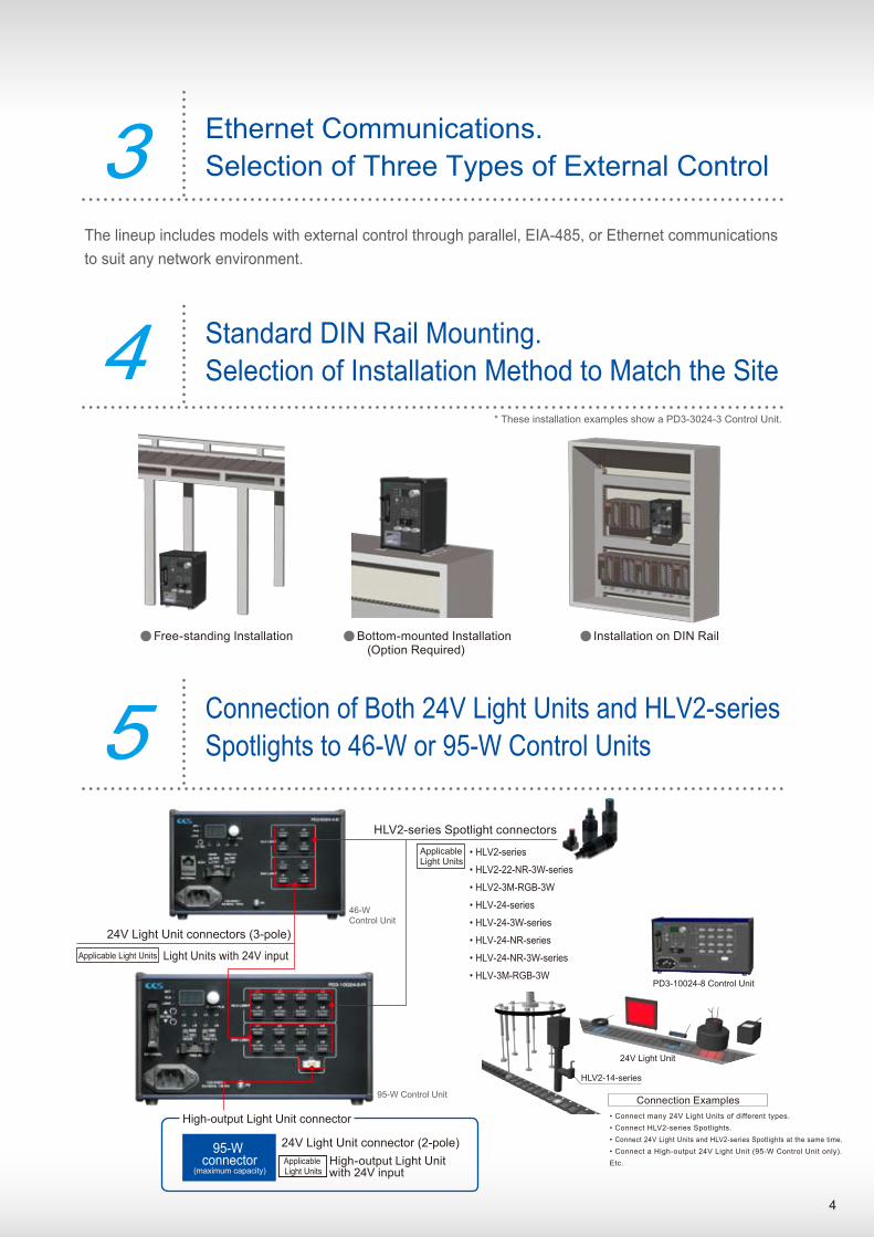
The lineup includes models with external control through parallel, EIA-485, or Ethernet communications to suit any network environment.
Ethernet Communications.Selection of Three Types of External Control3
Connection of Both 24V Light Units and HLV2-series Spotlights to 46-W or 95-W Control Units5
24V Light Unit connector (2-pole)95-W connector
HLV2-series Spotlight connectors
• HLV2-series
• HLV2-22-NR-3W-series
• HLV2-3M-RGB-3W
• HLV-24-series
• HLV-24-3W-series
• HLV-24-NR-series
• HLV-24-NR-3W-series
• HLV-3M-RGB-3W
High-output Light Unit connector
Standard DIN Rail Mounting.Selection of Installation Method to Match the Site4
Installation on DIN RailBottom-mounted Installation (Option Required)
Free-standing Installation
* These installation examples show a PD3-3024-3 Control Unit.
24V Light Unit connectors (3-pole)
Light Units with 24V input
HLV2-14-series
24V Light Unit
PD3-10024-8 Control Unit
Applicable Light Units
Applicable Light Units
High-output Light Unit with 24V input
Applicable Light Units
4
Connection Examples• Connect many 24V Light Units of different types.• Connect HLV2-series Spotlights.• Connect 24V Light Units and HLV2-series Spotlights at the same time.• Connect a High-output 24V Light Unit (95-W Control Unit only).Etc.
46-W Control Unit
95-W Control Unit
(maximum capacity)
5
Parallel
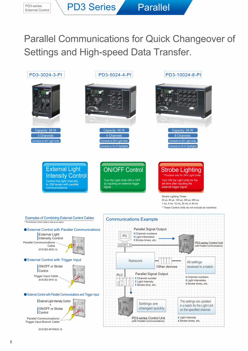
Parallel Communications for Quick Changeover of Settings and High-speed Data Transfer.
External Light Intensity ControlControl the light intensity to 256 levels with parallel communications.
ON/OFF ControlTurn the Light Units ON or OFF by inputting an external trigger signal.
Strobe Lighting Times40 µs, 80 µs, 120 µs, 200 µs, 600 µs, 1 ms, 4 ms, 10 ms, 20 ms, or 40 ms* These Control Units do not include an overdrive.
Strobe LightingTurn ON the Light Units for the set time after inputting the external trigger signal.
* Possible only for 24V Light Units.
PD3-series Control Unit(with Parallel Communications)
PD3-series Control Unit(with Parallel Communications)
PC
Parallel Signal Output
PLC
Channel numbersLight IntensitiesStrobe times, etc.
Parallel Signal OutputChannel numberLight IntensityStrobe time, etc.
Channel numbersLight IntensitiesStrobe times, etc.
All settings received in a batch.
Light IntensityStrobe times, etc.
The settings are updated in a batch for the Light Unit on the specified channel.
Settings are changed quickly.
Other devices
Network
PD3 Series
Communications Example* The External Control Cable is sold as an option.
Examples of Combining External Control Cables
External Light Intensity Control
Parallel CommunicationsCable
(EXCB2-M20-3)
PD3-3024-3-PI PD3-5024-4-PI PD3-10024-8-PI
PD3-series External Control
Capacity: 46 W
4 Channels
Connects to 24V Light Units
Connects to HLV2 Spotlights
Capacity: 95 W
8 Channels
Connects to 24V Light Units
Connects to HLV2 Spotlights
External Control with Parallel Communications
ON/OFF or Strobe Control
Trigger Input Cable(EXCB2-M10-3)
External Control with Trigger Input
External Light Intensity Control +ON/OFF or Strobe Control
Parallel Communications/Trigger Input Branch Cable
(EXCB2-M10M20-3)
External Control with Parallel Communications and Trigger Input
Capacity: 28 W
3 Channels
Connects to 24V Light Units
6
External Light Intensity Control
Strobe Lighting Times40 µs, 80 µs, 120 µs, 200 µs, 600 µs, 1 ms, 4 ms, 10 ms, 20 ms, or 40 ms* These Control Units do not include an overdrive.
Strobe LightingTurn ON the Light Units for the set time after inputting the external trigger signal.
* Possible only for 24V Light Units.
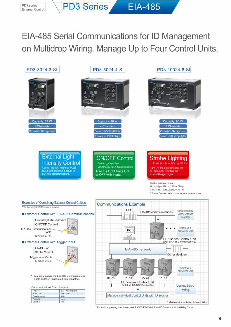
* For multidrop wiring, use the optional EXCB2-E3-E3-0.2 EIA-485 Communications Relay Cable.
PD3 Series
EIA-485 Serial Communications for ID Management on Multidrop Wiring. Manage Up to Four Control Units.
Communications Example* The External Control Cable is sold as an option.
Communications SpecificationsProtocolBaud rateData bit lengthParity bitStop bits
EIA-485 compliant19200 bps8 bitsNone1 bit
You can also use the EIA-485 Communications Cable and the Trigger Input Cable together.
*
Examples of Combining External Control Cables
External Light Intensity ControlON/OFF Control
EIA-485 CommunicationsCable
(EXCB2-E3-3)
ON/OFF or Strobe Control
Trigger Input Cable(EXCB2-M10-3)
PD3-3024-3-SI PD3-5024-4-SI PD3-10024-8-SI
EIA-485 communications
PD3-series Control Unit (with EIA-485 Communications)
PD3-series Control Unit (with EIA-485 Communications)
PC
PLC
Other devices
ID: 03 ID: 02 ID: 01 ID: 00
Manage up to four Control Units
Use multidrop wiring.
Manage up to four Control Units
Manage individual Control Units with
ID settings
EIA-485 network
Manage individual Control Units with ID settings
EIA-485
ON/OFF Control
Turn the Light Units ON or OFF with inputs.
• External trigger signal input• Command input via EIA-485 communicationsControl the light intensity to 256
levels with command inputs on EIA-485 communications.
* Maximum transmission distance: 30 m
Capacity: 28 W
3 Channels
Connects to 24V Light Units
Capacity: 46 W
4 Channels
Connects to 24V Light Units
Connects to HLV2 Spotlights
Capacity: 95 W
8 Channels
Connects to 24V Light Units
Connects to HLV2 Spotlights
External Control with EIA-485 Communications
External Control with Trigger Input
PD3-series External Control
7
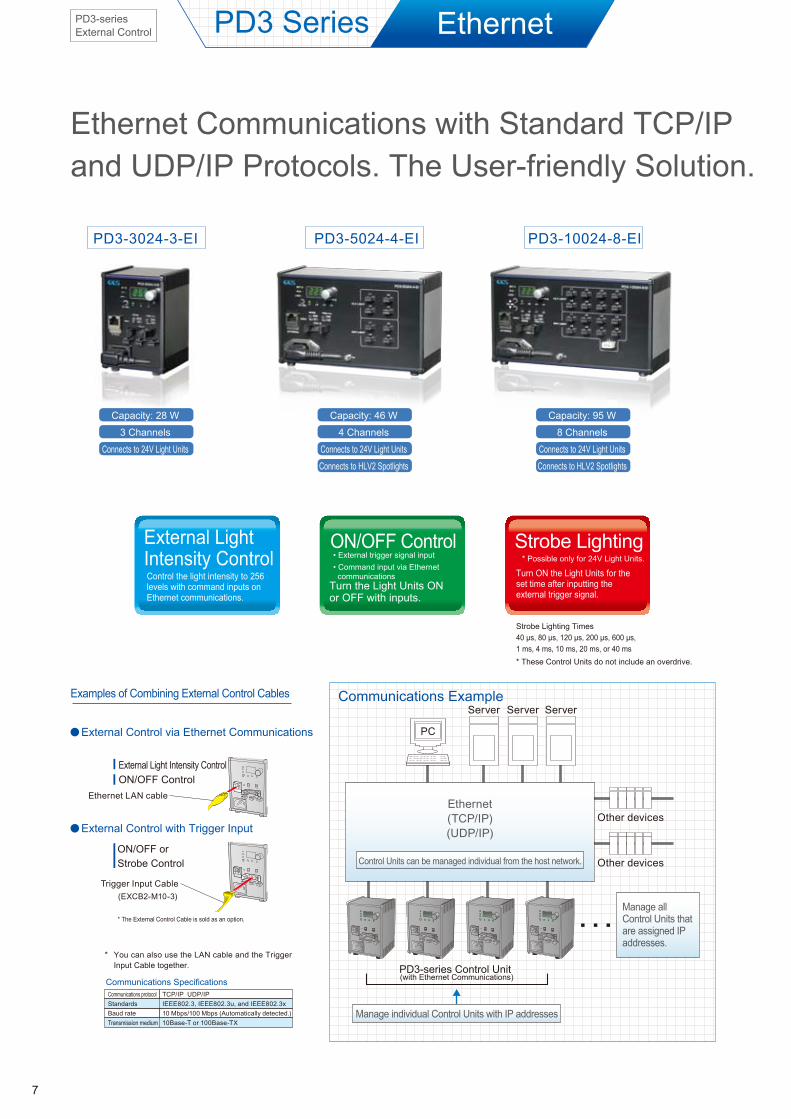
Ethernet Communications with Standard TCP/IP and UDP/IP Protocols. The User-friendly Solution.
EthernetPD3 Series
Communications Example
PD3-3024-3-EI PD3-5024-4-EI PD3-10024-8-EI
Other devices
Other devices
PD3-series Control Unit (with Ethernet Communications)
Manage individual Control Units with IP addresses
PC
Server Server Server
Ethernet(TCP/IP)(UDP/IP)
Manage all Control Units that are assigned IP addresses.
Control Units can be managed individual from the host network.
ON/OFF Control
Strobe Lighting Times40 µs, 80 µs, 120 µs, 200 µs, 600 µs, 1 ms, 4 ms, 10 ms, 20 ms, or 40 ms* These Control Units do not include an overdrive.
Strobe LightingTurn ON the Light Units for the set time after inputting the external trigger signal.
* Possible only for 24V Light Units.
Examples of Combining External Control Cables
Communications protocolStandardsBaud rateTransmission medium
TCP/IP UDP/IPIEEE802.3, IEEE802.3u, and IEEE802.3x10 Mbps/100 Mbps (Automatically detected.)10Base-T or 100Base-TX
Communications Specifications
You can also use the LAN cable and the Trigger Input Cable together.
*
External Light Intensity ControlON/OFF Control
Trigger Input Cable(EXCB2-M10-3)
Ethernet LAN cable
* The External Control Cable is sold as an option.
Turn the Light Units ON or OFF with inputs.
• External trigger signal input
• Command input via Ethernet
communications
External Light Intensity ControlControl the light intensity to 256 levels with command inputs on Ethernet communications.
Capacity: 28 W
3 Channels
Connects to 24V Light Units
Capacity: 46 W
4 Channels
Connects to 24V Light Units
Connects to HLV2 Spotlights
Capacity: 95 W
8 Channels
Connects to 24V Light Units
Connects to HLV2 Spotlights
External Control via Ethernet Communications
ON/OFF or Strobe Control
External Control with Trigger Input
PD3-series External Control
8
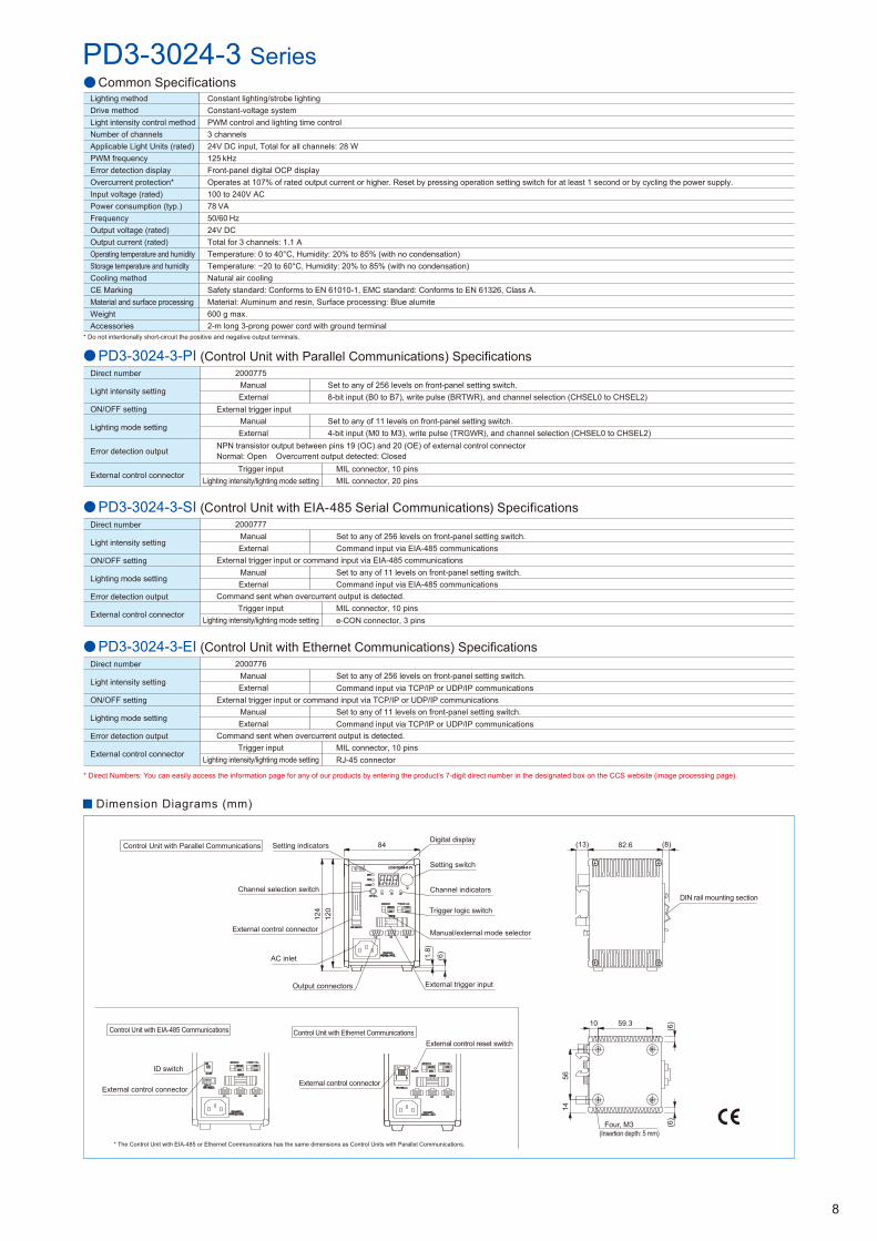
Common Specifications
* Do not intentionally short-circuit the positive and negative output terminals.
Lighting methodDrive methodLight intensity control methodNumber of channelsApplicable Light Units (rated)PWM frequencyError detection displayOvercurrent protection*Input voltage (rated)Power consumption (typ.)FrequencyOutput voltage (rated)Output current (rated)Operating temperature and humidityStorage temperature and humidityCooling methodCE MarkingMaterial and surface processingWeightAccessories
Constant lighting/strobe lightingConstant-voltage systemPWM control and lighting time control3 channels24V DC input, Total for all channels: 28 W125 kHzFront-panel digital OCP displayOperates at 107% of rated output current or higher. Reset by pressing operation setting switch for at least 1 second or by cycling the power supply.100 to 240V AC78 VA50/60 Hz24V DCTotal for 3 channels: 1.1 ATemperature: 0 to 40°C, Humidity: 20% to 85% (with no condensation)Temperature: −20 to 60°C, Humidity: 20% to 85% (with no condensation)
Natural air coolingSafety standard: Conforms to EN 61010-1, EMC standard: Conforms to EN 61326, Class A.Material: Aluminum and resin, Surface processing: Blue alumite600 g max.2-m long 3-prong power cord with ground terminal
PD3-3024-3-SI (Control Unit with EIA-485 Serial Communications) SpecificationsDirect number
Light intensity setting
ON/OFF setting
Lighting mode setting
Error detection output
External control connector
Command sent when overcurrent output is detected.
External trigger input or command input via EIA-485 communications
2000777ManualExternal
ManualExternal
Set to any of 256 levels on front-panel setting switch.Command input via EIA-485 communications
Trigger inputLighting intensity/lighting mode setting
MIL connector, 10 pinse-CON connector, 3 pins
Set to any of 11 levels on front-panel setting switch.Command input via EIA-485 communications
PD3-3024-3-PI (Control Unit with Parallel Communications) SpecificationsDirect number
Light intensity setting
ON/OFF setting
Lighting mode setting
Error detection output
External control connector
Set to any of 256 levels on front-panel setting switch.8-bit input (B0 to B7), write pulse (BRTWR), and channel selection (CHSEL0 to CHSEL2)
Trigger inputLighting intensity/lighting mode setting
MIL connector, 10 pinsMIL connector, 20 pins
NPN transistor output between pins 19 (OC) and 20 (OE) of external control connectorNormal: Open Overcurrent output detected: Closed
2000775ManualExternal
External trigger inputManualExternal
Set to any of 11 levels on front-panel setting switch.4-bit input (M0 to M3), write pulse (TRGWR), and channel selection (CHSEL0 to CHSEL2)
* Direct Numbers: You can easily access the information page for any of our products by entering the product’s 7-digit direct number in the designated box on the CCS website (image processing page).
PD3-3024-3-EI (Control Unit with Ethernet Communications) Specifications
External trigger input or command input via TCP/IP or UDP/IP communications
Direct number
Light intensity setting
ON/OFF setting
Lighting mode setting
Error detection output
External control connector
Command sent when overcurrent output is detected.
2000776ManualExternal
ManualExternal
Set to any of 256 levels on front-panel setting switch.Command input via TCP/IP or UDP/IP communications
Trigger inputLighting intensity/lighting mode setting
MIL connector, 10 pinsRJ-45 connector
Set to any of 11 levels on front-panel setting switch.Command input via TCP/IP or UDP/IP communications
PD3-3024-3 Series
Dimension Diagrams (mm)
Control Unit with Parallel Communications
* The Control Unit with EIA-485 or Ethernet Communications has the same dimensions as Control Units with Parallel Communications.
Control Unit with Ethernet Communications
External control connector
External control reset switch
Control Unit with EIA-485 Communications
External control connector
ID switch
Output connectors
Setting indicators
Channel selection switch
AC inlet
External control connector
Setting switch
Channel indicators
Digital display
Trigger logic switch
External trigger input
Manual/external mode selector
120
124
84
(6)
(1.8
)
56
Four, M3(Insertion depth: 5 mm)
14
59.310
(6)
(6)
82.6 (8)(13)
DIN rail mounting section
9
Control Unit with Parallel Communications
Common Specifications
PD3-5024-4 Series
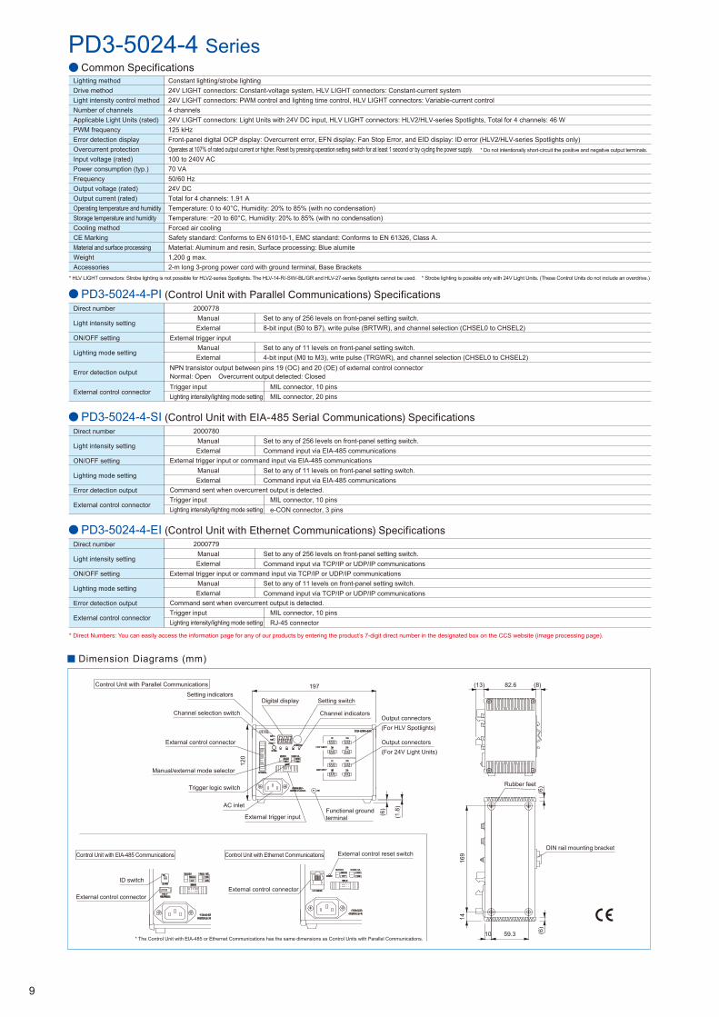
* Do not intentionally short-circuit the positive and negative output terminals.
Lighting methodDrive methodLight intensity control methodNumber of channelsApplicable Light Units (rated)PWM frequencyError detection displayOvercurrent protectionInput voltage (rated)Power consumption (typ.)FrequencyOutput voltage (rated)Output current (rated)Operating temperature and humidityStorage temperature and humidityCooling methodCE MarkingMaterial and surface processingWeightAccessories
Constant lighting/strobe lighting24V LIGHT connectors: Constant-voltage system, HLV LIGHT connectors: Constant-current system24V LIGHT connectors: PWM control and lighting time control, HLV LIGHT connectors: Variable-current control4 channels24V LIGHT connectors: Light Units with 24V DC input, HLV LIGHT connectors: HLV2/HLV-series Spotlights, Total for 4 channels: 46 W125 kHzFront-panel digital OCP display: Overcurrent error, EFN display: Fan Stop Error, and EID display: ID error (HLV2/HLV-series Spotlights only)Operates at 107% of rated output current or higher. Reset by pressing operation setting switch for at least 1 second or by cycling the power supply.100 to 240V AC70 VA50/60 Hz24V DCTotal for 4 channels: 1.91 ATemperature: 0 to 40°C, Humidity: 20% to 85% (with no condensation)Temperature: −20 to 60°C, Humidity: 20% to 85% (with no condensation)
Forced air coolingSafety standard: Conforms to EN 61010-1, EMC standard: Conforms to EN 61326, Class A.Material: Aluminum and resin, Surface processing: Blue alumite1,200 g max.2-m long 3-prong power cord with ground terminal, Base Brackets
* Direct Numbers: You can easily access the information page for any of our products by entering the product’s 7-digit direct number in the designated box on the CCS website (image processing page).
Dimension Diagrams (mm)
(6)
197
120
(6)
(1.8
)
Setting indicators
Channel selection switch
External control connector
Digital display Setting switch
Channel indicators
Manual/external mode selector
Trigger logic switch
AC inlet
External trigger input
Output connectors(For HLV Spotlights)
Output connectors(For 24V Light Units)
Functional ground terminal
82.6(13) (8)
1416
9
10 59.3
(6)Rubber feet
DIN rail mounting bracket
External control connector
External control reset switchControl Unit with Ethernet Communications
* The Control Unit with EIA-485 or Ethernet Communications has the same dimensions as Control Units with Parallel Communications.
Control Unit with EIA-485 Communications
External control connector
ID switch
* Strobe lighting is possible only with 24V Light Units. (These Control Units do not include an overdrive.)* HLV LIGHT connectors: Strobe lighting is not possible for HLV2-series Spotlights. The HLV-14-R/-SW/-BL/GR and HLV-27-series Spotlights cannot be used.
PD3-5024-4-PI (Control Unit with Parallel Communications) SpecificationsDirect number
Light intensity setting
ON/OFF setting
Lighting mode setting
Error detection output
External control connector
Set to any of 256 levels on front-panel setting switch.8-bit input (B0 to B7), write pulse (BRTWR), and channel selection (CHSEL0 to CHSEL2)
Trigger inputLighting intensity/lighting mode setting
MIL connector, 10 pinsMIL connector, 20 pins
NPN transistor output between pins 19 (OC) and 20 (OE) of external control connectorNormal: Open Overcurrent output detected: Closed
2000778ManualExternal
External trigger inputManualExternal
Set to any of 11 levels on front-panel setting switch.4-bit input (M0 to M3), write pulse (TRGWR), and channel selection (CHSEL0 to CHSEL2)
PD3-5024-4-SI (Control Unit with EIA-485 Serial Communications) SpecificationsDirect number
Light intensity setting
ON/OFF setting
Lighting mode setting
Error detection output
External control connector
Command sent when overcurrent output is detected.
External trigger input or command input via EIA-485 communications
2000780ManualExternal
ManualExternal
Set to any of 256 levels on front-panel setting switch.Command input via EIA-485 communications
Trigger inputLighting intensity/lighting mode setting
MIL connector, 10 pinse-CON connector, 3 pins
Set to any of 11 levels on front-panel setting switch.Command input via EIA-485 communications
PD3-5024-4-EI (Control Unit with Ethernet Communications) Specifications
External trigger input or command input via TCP/IP or UDP/IP communications
Direct number
Light intensity setting
ON/OFF setting
Lighting mode setting
Error detection output
External control connector
Command sent when overcurrent output is detected.
2000779ManualExternal
ManualExternal
Set to any of 256 levels on front-panel setting switch.Command input via TCP/IP or UDP/IP communications
Trigger inputLighting intensity/lighting mode setting
MIL connector, 10 pinsRJ-45 connector
Set to any of 11 levels on front-panel setting switch.Command input via TCP/IP or UDP/IP communications
10
Control Unit with Parallel Communications
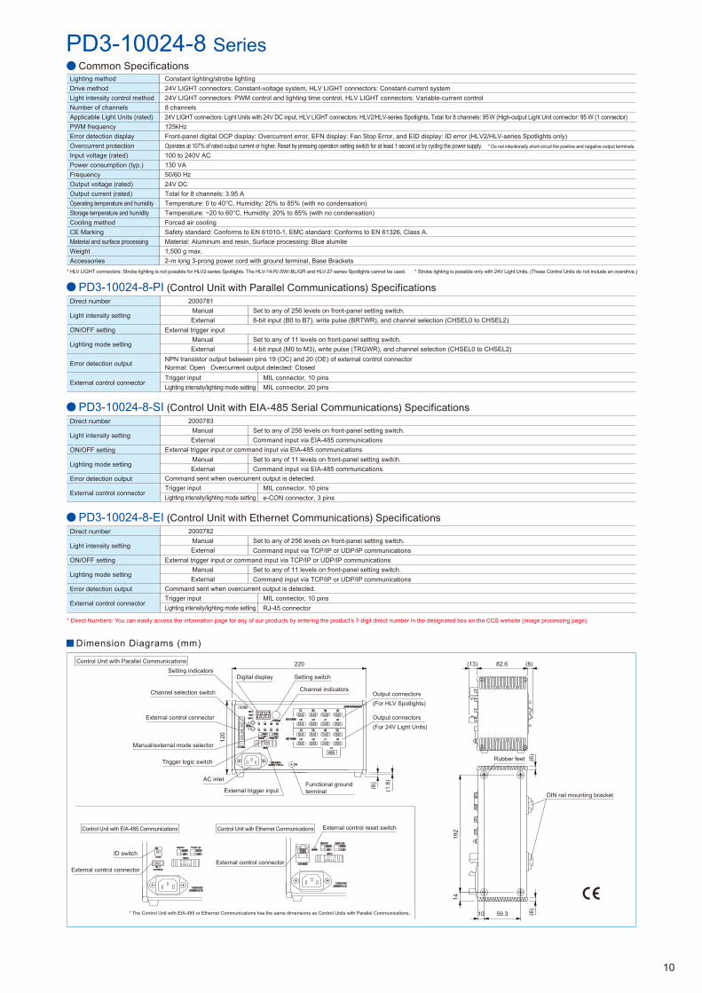
Common Specifications
* Do not intentionally short-circuit the positive and negative output terminals.
Lighting methodDrive methodLight intensity control methodNumber of channelsApplicable Light Units (rated)PWM frequencyError detection displayOvercurrent protectionInput voltage (rated)Power consumption (typ.)FrequencyOutput voltage (rated)Output current (rated)Operating temperature and humidityStorage temperature and humidityCooling methodCE MarkingMaterial and surface processingWeightAccessories
Constant lighting/strobe lighting24V LIGHT connectors: Constant-voltage system, HLV LIGHT connectors: Constant-current system24V LIGHT connectors: PWM control and lighting time control, HLV LIGHT connectors: Variable-current control8 channels24V LIGHT connectors: Light Units with 24V DC input, HLV LIGHT connectors: HLV2/HLV-series Spotlights, Total for 8 channels: 95 W (High-output Light Unit connector: 95 W (1 connector)125kHzFront-panel digital OCP display: Overcurrent error, EFN display: Fan Stop Error, and EID display: ID error (HLV2/HLV-series Spotlights only)Operates at 107% of rated output current or higher. Reset by pressing operation setting switch for at least 1 second or by cycling the power supply.100 to 240V AC130 VA50/60 Hz24V DCTotal for 8 channels: 3.95 ATemperature: 0 to 40°C, Humidity: 20% to 85% (with no condensation)Temperature: −20 to 60°C, Humidity: 20% to 85% (with no condensation)
Forced air coolingSafety standard: Conforms to EN 61010-1, EMC standard: Conforms to EN 61326, Class A.Material: Aluminum and resin, Surface processing: Blue alumite1,500 g max.2-m long 3-prong power cord with ground terminal, Base Brackets
PD3-10024-8 Series
Dimension Diagrams (mm)
AC inlet
External trigger input
(6)
(6)
(1.8
)
10 59.3
82.6(13) (8)Setting indicators
Channel selection switch
External control connector
Digital display Setting switch
Channel indicators
Manual/external mode selector
Trigger logic switch
Output connectors(For HLV Spotlights)
Output connectors(For 24V Light Units)
Functional ground terminal
Rubber feet
DIN rail mounting bracket
External control connector
External control reset switchControl Unit with Ethernet Communications
* The Control Unit with EIA-485 or Ethernet Communications has the same dimensions as Control Units with Parallel Communications.
Control Unit with EIA-485 Communications
External control connector
ID switch
220
120
192
14
(6)
* Strobe lighting is possible only with 24V Light Units. (These Control Units do not include an overdrive.)* HLV LIGHT connectors: Strobe lighting is not possible for HLV2-series Spotlights. The HLV-14-R/-SW/-BL/GR and HLV-27-series Spotlights cannot be used.
PD3-10024-8-PI (Control Unit with Parallel Communications) SpecificationsDirect number
Light intensity setting
ON/OFF setting
Lighting mode setting
Error detection output
External control connector
Set to any of 256 levels on front-panel setting switch.8-bit input (B0 to B7), write pulse (BRTWR), and channel selection (CHSEL0 to CHSEL2)
Trigger inputLighting intensity/lighting mode setting
MIL connector, 10 pinsMIL connector, 20 pins
NPN transistor output between pins 19 (OC) and 20 (OE) of external control connectorNormal: Open Overcurrent output detected: Closed
2000781ManualExternal
External trigger inputManualExternal
Set to any of 11 levels on front-panel setting switch.4-bit input (M0 to M3), write pulse (TRGWR), and channel selection (CHSEL0 to CHSEL2)
PD3-10024-8-SI (Control Unit with EIA-485 Serial Communications) SpecificationsDirect number
Light intensity setting
ON/OFF setting
Lighting mode setting
Error detection output
External control connector
Command sent when overcurrent output is detected.
External trigger input or command input via EIA-485 communications
2000783ManualExternal
ManualExternal
Set to any of 256 levels on front-panel setting switch.Command input via EIA-485 communications
Trigger inputLighting intensity/lighting mode setting
MIL connector, 10 pinse-CON connector, 3 pins
Set to any of 11 levels on front-panel setting switch.Command input via EIA-485 communications
* Direct Numbers: You can easily access the information page for any of our products by entering the product’s 7-digit direct number in the designated box on the CCS website (image processing page).
PD3-10024-8-EI (Control Unit with Ethernet Communications) Specifications
External trigger input or command input via TCP/IP or UDP/IP communications
Direct number
Light intensity setting
ON/OFF setting
Lighting mode setting
Error detection output
External control connector
Command sent when overcurrent output is detected.
2000782ManualExternal
ManualExternal
Set to any of 256 levels on front-panel setting switch.Command input via TCP/IP or UDP/IP communications
Trigger inputLighting intensity/lighting mode setting
MIL connector, 10 pinsRJ-45 connector
Set to any of 11 levels on front-panel setting switch.Command input via TCP/IP or UDP/IP communications

External Control Cables
Base Brackets
Dimension Diagrams (mm)
These Brackets are used to secure a PD3-series Control Unit to the floor, a shelve, or other surface.
Parallel Communications CableThis Cable is used for external control with parallel communications. The channel, light intensity setting, and lighting mode (constant mode, ON/OFF mode, or strobe mode) can be selected.
Options
Direct number: 3000683Model: EXCB2-M20-3
20-pin MIL connector
3000
6.1
dia.
21
2019
1 2
19 20Cut off on one end
PIN No. Wire color Marks1 Orange Black 12 Orange Red 13 Gray Black 14 Gray Red 15 White Black 16 White Red 17 Yellow Black 18 Yellow Red 19 Pink Black 110 Pink Red 1
PIN No. Wire color Marks11 Orange Black 212 Orange Red 213 Gray Black 214 Gray Red 215 White Black 216 White Red 217 Yellow Black 218 Yellow Red 219 Pink Black 220 Pink Red 2
Direct number: 3000682Model: EXCB2-M10-3
Direct number: 3000685Model: EXCB2-E3-3
Direct number: 3000721Model: EXCB2-E3-E3-0.2
Direct number: 3000684Model: EXCB2-M10M20-3
Direct number: 4001164Model: BK-PD3
This Cable is required to connect two or more PD3-ser ies Cont ro l Un i ts w i th EIA-485 communications.
T h i s C a b l e i n c l u d e s t h e P a r a l l e l Communications Cable and the Trigger Input Cable in one cable.
* The Base Brackets are included with the PD3-5024-4 and PD3-10024-8 Control Units.
Parallel Communications/Trigger Input Branch Cable
Trigger Input CableThis cable is used to input an external t r igger signal using paral le l bi ts. The external trigger signal can be used to turn Light Units ON or OFF, or to f lash the strobes.
This Cable is used for external control with EIA-485 communications. The channel, light intensity setting, ON/OFF setting, and lighting mode (constant mode, ON/OFF mode, or strobe mode) can be selected.
EIA-485 Serial Communications Cable
10-pin MIL connector
3000
5 di
a.
1 2
9 10
1 2
9 10 Cut off on one end
PIN No. Wire color Marks1 Orange Black 12 Orange Red 13 Gray Black 14 Gray Red 15 White Black 16 White Red 17 Yellow Black 18 Yellow Red 19 Pink Black 1
10 Pink Red 1
e-CON connector, 3 pins
3000
3.9
dia.
123
123
Cut off on one end
PIN No. Wire color Embedded line color1 Black None2 Black White
3 (shield) NoneDrain wire
Direct number: 3000720Model: ECNR-E3CN4
123
123
e-CON connector, 3 pins
3.9
dia.
200
3013.8
13
e-CON relay connector 3-pin, 4×4Relay connector
3000
100
7.2
dia.
21
9 10
10-pin MIL connector
21
19 20
20-pin MIL connector
1 2
19 20
1 2
9 10
Cut off on one end
70
Two, 3.5-dia. holesTwo, 4.5-dia. holes
59.3
29
40
195
(1)
5
10
* 1 set (2 Brackets)
PIN No. Wire color Marks1 Orange Black 22 Orange Red 23 Gray Black 24 Gray Red 25 White Black 26 White Red 27 Yellow Black 28 Yellow Red 29 Pink Black 210 Pink Red 211 Orange Black 312 Orange Red 313 Gray Black 314 Gray Red 315 White Black 316 White Red 317 Yellow Black 318 Yellow Red 319 Pink Black 320 Pink Red 3
20-pin MIL connector
PIN No. Wire color Marks1 Orange Black 12 Orange Red 13 Gray Black 14 Gray Red 15 White Black 16 White Red 17 Yellow Black 18 Yellow Red 19 Pink Black 1
10 Pink Red 1
10-pin MIL connector
Caution To ensure proper and safe use of the product, please read the Instruction Guide completely before using the product. For product improvement, specifications and designs are subject to change without notice.
Copyright(c) 2012 CCS Inc. All Rights Reserved. Descriptions in this catalog are based on information available as of January 2012. 02002-00-1201-PD3
Headquarters
Shimodachiuri-agaru, Karasuma-dori, Kamigyo-ku, Kyoto 602-8011 Japan Phone: +81-75-415-8284 / Fax: +81-75-415-8278 URL: http://www.ccs-grp.com E-mail: [email protected]
CCS and LIGHTING SOLUTION are all registered trademarks or trademarks of CCS, Inc.
EIA-485 Serial Communications Relay Cable