trade of metal fabrication -...
TRANSCRIPT
Trade of Metal Fabrication Module 6: Fabrication Drawing
Unit 1: Introduction to Fabrication Drawing
Phase 2

Trade of Metal Fabrication – Phase 2 Module 6 Unit 1
Unit 1 3
Table of Contents
List of Figures .................................................................................................................... 5
List of Tables ..................................................................................................................... 7
Document Release History ............................................................................................... 8
Module 6 – Fabrication Drawing..................................................................................... 9
Unit 1 – Introduction to Fabrication Drawing ................................................................ 9 Duration – 1.5 Hours ................................................................................................... 9 Learning Outcome: ..................................................................................................... 9 Key Learning Points: .................................................................................................. 9 Training Resources: .................................................................................................... 9 Key Learning Points Code: ......................................................................................... 9
Engineering Drawing ...................................................................................................... 10
Introduction ................................................................................................................... 10 Bearings ........................................................................................................................ 10
Ball and Roller Bearings ........................................................................................... 11 Spur Gears ..................................................................................................................... 13 Bevel Gears ................................................................................................................... 15 Radial Cams .................................................................................................................. 16
Technical Drawing and Design ...................................................................................... 18
Introduction ................................................................................................................... 18 The Place of Technical Drawing in Designing ............................................................. 20
Purpose of Technical Drawing ....................................................................................... 20
Why Then Learn Technical Drawing? .......................................................................... 20
Pictorial Drawing ............................................................................................................ 21
Introduction ................................................................................................................... 21 Isometric Drawing ........................................................................................................ 21 Constructing Isometric Curves ..................................................................................... 22 Exploded Isometric Drawing ........................................................................................ 24
A Simple Exploded Isometric Drawing .................................................................... 24 An Exploded Isometric Drawing .............................................................................. 24
Freehand Drawing ......................................................................................................... 25 The 4-Arcs Method of Drawing Isometric Circles ....................................................... 28 Drawing Isometric Curves ............................................................................................ 30 Estimated One and Two-Point Perspective Drawing ................................................... 31
Estimated One-Point Perspective Drawing ............................................................... 31 Estimated Two-Point Perspective Drawing .............................................................. 32 Note: .......................................................................................................................... 32

Trade of Metal Fabrication – Phase 2 Module 6 Unit 1
Unit 1 4
Self Assessment................................................................................................................ 33
Answers to Questions 1-3. Module 6. Unit 1 ................................................................. 35
Index ................................................................................................................................. 38
Trade of Metal Fabrication – Phase 2 Module 6 Unit 1
Unit 1 5
List of Figures
Figure 1 - Bush and its Lubricating Hole.......................................................................... 10
Figure 2 - Standard Drawing Symbol for a Ball or Roller Bearing .................................. 11
Figure 3 - Sectional Views through a Roller Bearing - a Journal ..................................... 11
Figure 4 - Sections Through a Roller Bearing and a Needle Bearing – Journals ............. 12
Figure 5 - Thrust Bearing with Taper Rollers ................................................................... 12
Figure 6 - Standard Symbol for Two Meshing Spur Gears .............................................. 13
Figure 7 - Enlarged View of Involute Gear Teeth from Two Meshing Gears .................. 13
Figure 8 - Two Spur Gears in a Train ............................................................................... 14
Figure 9 - Gear Train of Three Spur Gears, the Middle One is an Idler Gear .................. 14
Figure 10 - Pair of Bevel Gears Drawn using Standard Technical Drawing Methods ..... 15
Figure 11 - Rotary Cams - Wedge Shaped and Roller Followers ..................................... 16
Figure 12 - Rotary Cams - Flat and Off-Line Followers .................................................. 16
Figure 13 - Arm and Roller Follower with a Rotary Cam ................................................ 17
Figure 14 - Cam System from an Overhead Valve System in a Car Engine .................... 17
Figure 15 - Flow Chart Describing a Design Process ....................................................... 18
Figure 16 - Isometric Drawing of a Rectangular Prism .................................................... 21
Figure 17 - Sizes must be taken along Isometric Axes ..................................................... 21
Figure 18 - Finished Isometric Drawing to the Sizes in Figure 17 ................................... 21
Figure 19 - Sloping Lines - Sizes must be measured along Axes ..................................... 21
Figure 20 - Method of Constructing an Isometric Circle .................................................. 22
Figure 21 - Other Positions for Isometric Circles ............................................................. 22
Figure 22 - Simple Isometric Drawing ............................................................................. 23
Figure 23 - Simple Isometric Drawing involving Circles ................................................. 23
Figure 24 - Simple Exploded Isometric Drawing ............................................................. 24
Figure 25 - Exploded Isometric Drawing ......................................................................... 24
Figure 26 - Freehand Drawing on an A3 Sheet of 10mm Square Grid Paper .................. 25
Figure 27 - Example of Freehand Drawing on 10mm Square Grid Paper ........................ 26
Figure 28 - Freehand Drawing of an Orthographic Projection on Plain Paper without Grid Lines .......................................................................................................................... 26
Figure 29 - Freehand Isometric Drawing on Isometric Grid Paper with Line Spacing at 10mm ........................................................................................................................ 27
Figure 30 - Freehand Drawing on Isometric Lines on Plain Paper without Grid Lines ... 27
Figure 31 - The 4-Arcs Method of Constructing an Isometric Ellipse ............................. 28
Figure 32 - The 4-Arcs Method used in other Isometric Positions ................................... 29

Trade of Metal Fabrication – Phase 2 Module 6 Unit 1
Unit 1 6
Figure 33 - Example of an Isometric Drawing involving Isometric Ellipses on Three Faces using the 4-Arcs Method of Construction....................................................... 29
Figure 34 - Example of drawing an Isometric Curve using the Ordinate Method of Construction .............................................................................................................. 30
Figure 35 - Example of a One-Point Perspective Drawing ............................................... 31
Figure 36 - One-Point Perspective Drawing which Includes an Arc ................................ 31
Figure 37 - Example of Two-Point Perspective ................................................................ 32

Trade of Metal Fabrication – Phase 2 Module 6 Unit 1
Unit 1 7
List of Tables

Trade of Metal Fabrication – Phase 2 Module 6 Unit 1
Unit 1 8
Document Release History
Date Version Comments
19/02/07 First draft
13/12/13 SOLAS transfer
Trade of Metal Fabrication – Phase 2 Module 6 Unit 1
Unit 1 9
Module 6 – Fabrication Drawing
Unit 1 – Introduction to Fabrication Drawing
Duration – 1.5 Hours
Learning Outcome:
By the end of this unit each apprentice will be able to:
State the purpose of Engineering drawings
Identify the different types of technical drawings
State the information to be found on drawings
Interpret information from technical drawings
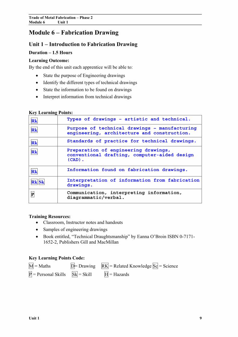
Key Learning Points:
Rk Types of drawings – artistic and technical.
Rk Purpose of technical drawings – manufacturing engineering, architecture and construction.
Rk Standards of practice for technical drawings.
Rk Preparation of engineering drawings, conventional drafting, computer-aided design (CAD).
Rk Information found on fabrication drawings.
Rk Sk Interpretation of information from fabrication drawings.
P Communication, interpreting information, diagrammatic/verbal.
Training Resources: Classroom, Instructor notes and handouts
Samples of engineering drawings
Book entitled, “Technical Draughtsmanship” by Eanna O’Broin ISBN 0-7171-1652-2, Publishers Gill and MacMillan
Key Learning Points Code:
M = Maths D= Drawing RK = Related Knowledge Sc = Science
P = Personal Skills Sk = Skill H = Hazards
Trade of Metal Fabrication – Phase 2 Module 6 Unit 1
Unit 1 10
Engineering Drawing
Introduction
This section describes the type of working drawings used in engineering. In order to draw and understand engineering drawings, some knowledge of features such as bearings in which spindles rotate, gears for transmitting motion between rotating parts and cams for changing rotation into straight-line motion, is necessary. Basic principles concerned with these features are described, together with examples of and exercises in engineering drawing.
Bearings
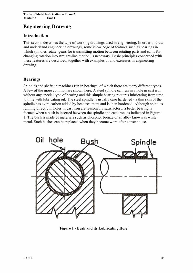
Spindles and shafts in machines run in bearings, of which there are many different types. A few of the more common are shown here. A steel spindle can run in a hole in cast iron without any special type of bearing and this simple bearing requires lubricating from time to time with lubricating oil. The steel spindle is usually case hardened - a thin skin of the spindle has extra carbon added by heat treatment and is then hardened. Although spindles running directly in holes in cast iron are reasonably satisfactory, a better bearing is formed when a bush is inserted between the spindle and cast iron, as indicated in Figure 1. The bush is made of materials such as phosphor bronze or an alloy known as white metal. Such bushes can be replaced when they become worn after constant use.
Figure 1 - Bush and its Lubricating Hole

Trade of Metal Fabrication – Phase 2 Module 6 Unit 1
Unit 1 11
Ball and Roller Bearings
One of the more common forms of bearings are those incorporating steel balls or rollers. Figure 2 shows the general symbol for drawing any form of ball or roller bearing. Figure 3 is a two-view orthographic projection of a roller bearing, both views being in section.
Figure 2 - Standard Drawing Symbol for a Ball or Roller Bearing
Figure 3 - Sectional Views through a Roller Bearing - a Journal
Trade of Metal Fabrication – Phase 2 Module 6 Unit 1
Unit 1 12
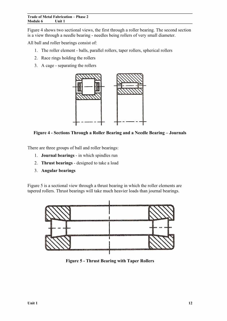
Figure 4 shows two sectional views, the first through a roller bearing. The second section is a view through a needle bearing - needles being rollers of very small diameter.
All ball and roller bearings consist of:
1. The roller element - balls, parallel rollers, taper rollers, spherical rollers
2. Race rings holding the rollers
3. A cage - separating the rollers
Figure 4 - Sections Through a Roller Bearing and a Needle Bearing – Journals
There are three groups of ball and roller bearings:
1. Journal bearings - in which spindles run
2. Thrust bearings - designed to take a load
3. Angular bearings
Figure 5 is a sectional view through a thrust bearing in which the roller elements are tapered rollers. Thrust bearings will take much heavier loads than journal bearings.
Figure 5 - Thrust Bearing with Taper Rollers

Trade of Metal Fabrication – Phase 2 Module 6 Unit 1
Unit 1 13
Spur Gears
For transferring rotation from one spindle (or shaft) to another, spur gears are commonly used. A spur gear is a circular disc with a central hole, usually with a keyway cut in it for fixing to a spindle via a key. The gear has a number of gear teeth cut around its circumference. The profile of gear teeth in the majority of spur gears is based on the involute to a circle. Some gears often those used in watches and clocks) are based on the cycloid to a circle.
The standard symbol for drawing spur gears in technical drawings is shown in Figure 6.
Figure 6 - Standard Symbol for Two Meshing Spur Gears
Note: that the base circle centre lines for each gear (on which the involute is based) meet tangentially.
Figure 7 shows a number of gear teeth taken from two meshing spur gears. It is most unlikely that you will be required to draw such gear teeth. Figure 7 shows the appearance of meshing involute gear teeth. In technical drawings use the symbols for spur gears, not the actual outlines of the gear teeth.
Figure 7 - Enlarged View of Involute Gear Teeth from Two Meshing Gears

Trade of Metal Fabrication – Phase 2 Module 6 Unit 1
Unit 1 14
Figure 8 is a Front view of a two-gear gear train. The rotation of either gear brings about a rotation in an opposite direction in the gear with which it is meshed. Thus the clockwise rotation of the left hand gear is translated into an anticlockwise rotation in the right hand gear.
Figure 8 - Two Spur Gears in a Train
Note the change in direction of rotation.
Figure 9 is another gear train, in which the rotation of the uppermost gear is repeated in the bottom gear using what is known as an idler gear.
Figure 9 - Gear Train of Three Spur Gears, the Middle One is an Idler Gear
Trade of Metal Fabrication – Phase 2 Module 6 Unit 1
Unit 1 15
Bevel Gears
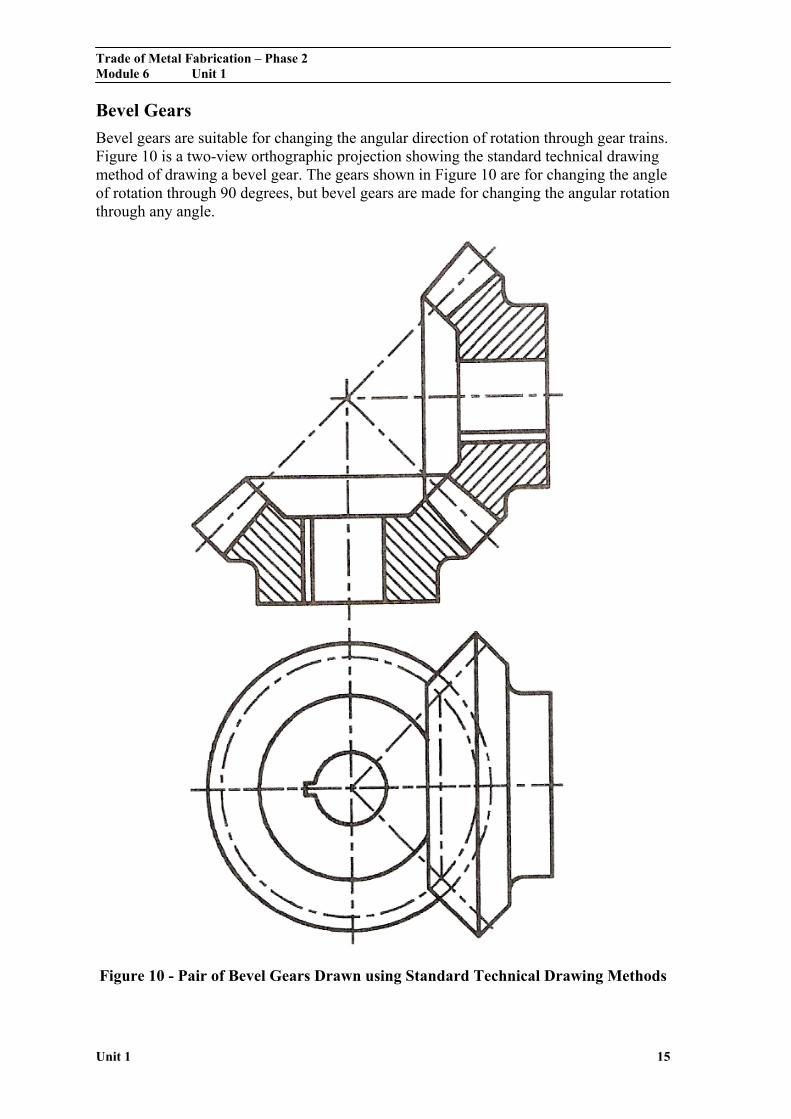
Bevel gears are suitable for changing the angular direction of rotation through gear trains. Figure 10 is a two-view orthographic projection showing the standard technical drawing method of drawing a bevel gear. The gears shown in Figure 10 are for changing the angle of rotation through 90 degrees, but bevel gears are made for changing the angular rotation through any angle.
Figure 10 - Pair of Bevel Gears Drawn using Standard Technical Drawing Methods
Trade of Metal Fabrication – Phase 2 Module 6 Unit 1
Unit 1 16
Radial Cams
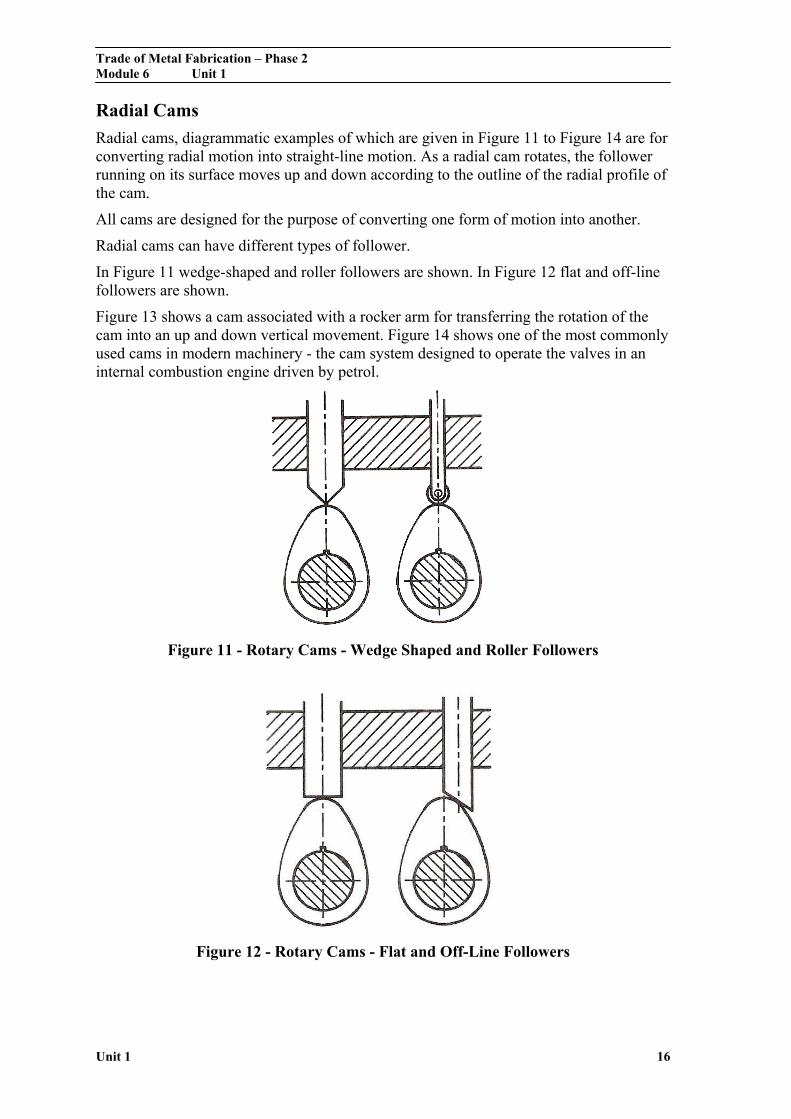
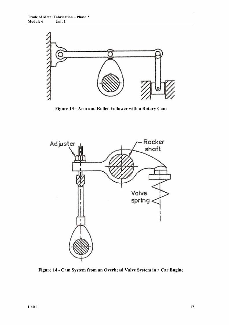
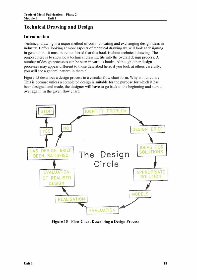
Radial cams, diagrammatic examples of which are given in Figure 11 to Figure 14 are for converting radial motion into straight-line motion. As a radial cam rotates, the follower running on its surface moves up and down according to the outline of the radial profile of the cam.
All cams are designed for the purpose of converting one form of motion into another.
Radial cams can have different types of follower.
In Figure 11 wedge-shaped and roller followers are shown. In Figure 12 flat and off-line followers are shown.
Figure 13 shows a cam associated with a rocker arm for transferring the rotation of the cam into an up and down vertical movement. Figure 14 shows one of the most commonly used cams in modern machinery - the cam system designed to operate the valves in an internal combustion engine driven by petrol.
Figure 11 - Rotary Cams - Wedge Shaped and Roller Followers
Figure 12 - Rotary Cams - Flat and Off-Line Followers
Trade of Metal Fabrication – Phase 2 Module 6 Unit 1
Unit 1 17
Figure 13 - Arm and Roller Follower with a Rotary Cam
Figure 14 - Cam System from an Overhead Valve System in a Car Engine
Trade of Metal Fabrication – Phase 2 Module 6 Unit 1
Unit 1 18
Technical Drawing and Design
Introduction
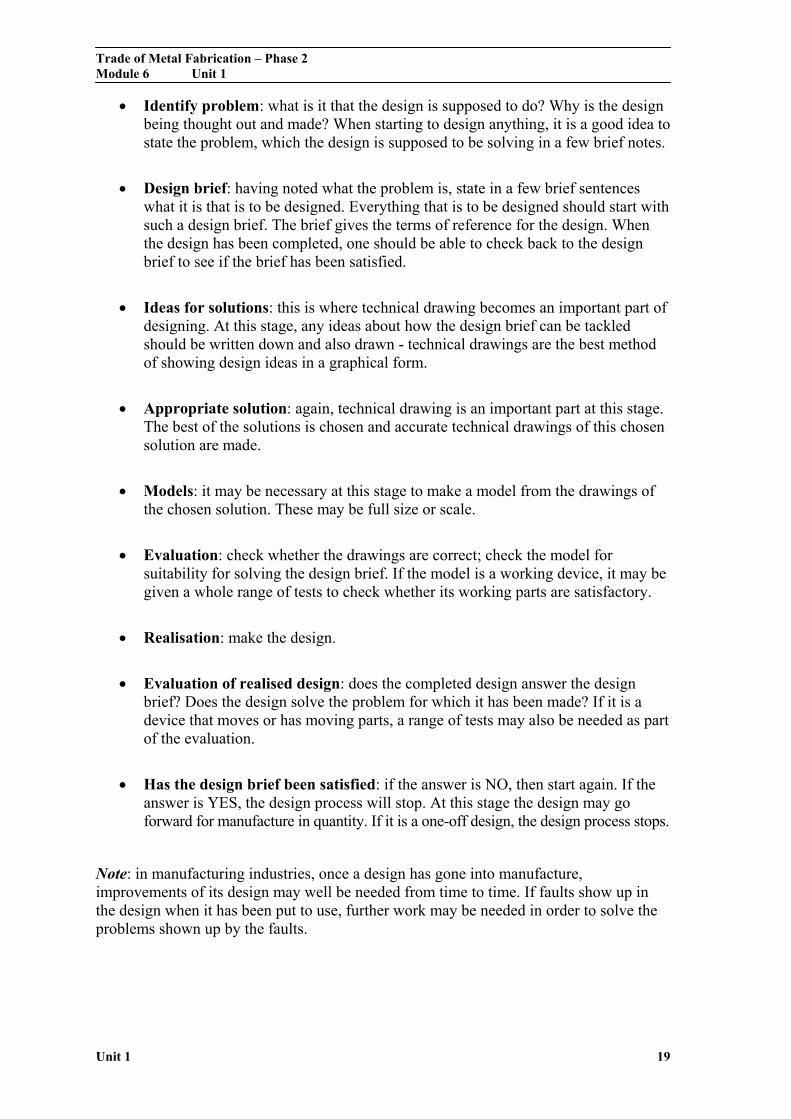
Technical drawing is a major method of communicating and exchanging design ideas in industry. Before looking at more aspects of technical drawing we will look at designing in general, but it must be remembered that this book is about technical drawing. The purpose here is to show how technical drawing fits into the overall design process. A number of design processes can be seen in various books. Although other design processes may appear different to those described here, if you look at others carefully, you will see a general pattern in them all. Figure 15 describes a design process in a circular flow chart form. Why is it circular? This is because unless a completed design is suitable for the purpose for which it has been designed and made, the designer will have to go back to the beginning and start all over again. In the given flow chart:
Figure 15 - Flow Chart Describing a Design Process
Trade of Metal Fabrication – Phase 2 Module 6 Unit 1
Unit 1 19
Identify problem: what is it that the design is supposed to do? Why is the design being thought out and made? When starting to design anything, it is a good idea to state the problem, which the design is supposed to be solving in a few brief notes.
Design brief: having noted what the problem is, state in a few brief sentences what it is that is to be designed. Everything that is to be designed should start with such a design brief. The brief gives the terms of reference for the design. When the design has been completed, one should be able to check back to the design brief to see if the brief has been satisfied.
Ideas for solutions: this is where technical drawing becomes an important part of designing. At this stage, any ideas about how the design brief can be tackled should be written down and also drawn - technical drawings are the best method of showing design ideas in a graphical form.
Appropriate solution: again, technical drawing is an important part at this stage. The best of the solutions is chosen and accurate technical drawings of this chosen solution are made.
Models: it may be necessary at this stage to make a model from the drawings of the chosen solution. These may be full size or scale.
Evaluation: check whether the drawings are correct; check the model for suitability for solving the design brief. If the model is a working device, it may be given a whole range of tests to check whether its working parts are satisfactory.
Realisation: make the design.
Evaluation of realised design: does the completed design answer the design brief? Does the design solve the problem for which it has been made? If it is a device that moves or has moving parts, a range of tests may also be needed as part of the evaluation.
Has the design brief been satisfied: if the answer is NO, then start again. If the answer is YES, the design process will stop. At this stage the design may go forward for manufacture in quantity. If it is a one-off design, the design process stops.
Note: in manufacturing industries, once a design has gone into manufacture, improvements of its design may well be needed from time to time. If faults show up in the design when it has been put to use, further work may be needed in order to solve the problems shown up by the faults.
Trade of Metal Fabrication – Phase 2 Module 6 Unit 1
Unit 1 20
The Place of Technical Drawing in Designing
As seen above, technical drawings play an important part in design problem solving. We are not dealing with the designing and making of articles, but only with the drawing skills so important in the design process. Because of this, the examples and exercises contained in its pages are based on:
1. Sufficient examples, exercises and practice for the reader to learn the skills necessary for constructing technical drawings.
2. A number of exercises, which will give the reader some practice in designing graphics using the technical drawing skills.
Purpose of Technical Drawing
Why Then Learn Technical Drawing?
Even the most skilled computer expert working as a draughtsman with a CAD system must have a good technical drawing background. Without a good knowledge of the practice of technical drawing methods learned 'at the drawing board', a CAD operator cannot produce technical drawings with his/her equipment. It is only by practising with the aid of drawing instruments that computer drawing skills can be gained. A good practical knowledge of plane and solid geometry, an understanding of the theory of orthographic projection, the use of good standard drawing conventions can only be learned by constant practice 'at the drawing board'. So - first learn how to produce good quality technical drawings 'by hand', then learn how to produce them with CAD.

Trade of Metal Fabrication – Phase 2 Module 6 Unit 1
Unit 1 21
Pictorial Drawing
Introduction
Pictorial drawings show a 'picture' of an article in three dimensions, as if one were looking at the article itself. Pictorial drawings are an important part of technical drawing. There are two main reasons for this:
1. Complex working drawings are sometimes very difficult to understand. Pictorial drawings of details in a complex drawing can help people to understand the drawing.
2. Pictorial drawings are an important part of showing people who cannot 'read' working drawings, what an article actually looks like.
Isometric Drawing
Isometric drawing is a form of pictorial drawing based on lines at 30 degrees from the horizontal. Figure 16 shows the basic idea when making an isometric drawing of a rectangular prism. Vertical lines are drawn with the aid of the right angle of a set square; lines at 30 degrees are drawn with the aid of a 30,60 set square.
When constructing an isometric drawing, all measurements must be made along the isometric axes - either the vertical lines or along the 30 degree lines. This applies even when constructing arcs or curved lines in isometric drawings. Figure 17 shows the method of finding the sizes along the isometric axes for the construction of Figure 18. Figure 19 shows how lines, which are not along the isometric axes, must be constructed from measurements taken along the axes.
Figure 16 - Isometric Drawing of a Rectangular Prism
Figure 17 - Sizes must be taken along Isometric Axes
Figure 18 - Finished Isometric Drawing to the Sizes in Figure 17
Figure 19 - Sloping Lines - Sizes must be measured along Axes

Trade of Metal Fabrication – Phase 2 Module 6 Unit 1
Unit 1 22
Constructing Isometric Curves
Figure 20 shows how an isometric circle is constructed:
1. Draw a circle of the required diameter - the lower drawing of Figure 20. Draw vertical lines - a, b and c - at any spacing across the circle.
2. Draw the two centre lines for the circle at 30 degrees each way - the upper drawing of Figure 20.
3. Mark off the lengths Oa, Ob and Oc, taken from the circle, along one of the isometric centre lines, each side of the centre O. Draw 30 degree lines through the points a, b and c.
4. Each side of the centre line from a, b and c mark off the lengths a1, b2 and c3 along the 30 degree lines from a, b and c.
5. Mark the lengths Od each side along the centre line in the isometric drawing.
6. All necessary points for drawing the isometric circle have now been found. Draw a fair curve through the points to complete the required isometric circle - which is an ellipse.
Figure 21 shows a similar construction for circles in other isometric positions.
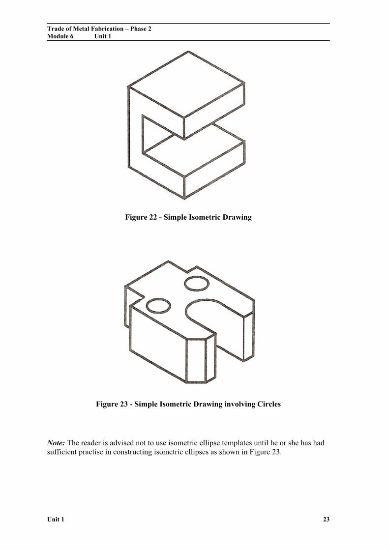
Figure 22 is an example of a simple isometric drawing and Figure 23 another example which includes isometric 'circles'.
Figure 20 - Method of Constructing an Isometric Circle
Figure 21 - Other Positions for Isometric Circles
Trade of Metal Fabrication – Phase 2 Module 6 Unit 1
Unit 1 23
Figure 22 - Simple Isometric Drawing
Figure 23 - Simple Isometric Drawing involving Circles
Note: The reader is advised not to use isometric ellipse templates until he or she has had sufficient practise in constructing isometric ellipses as shown in Figure 23.

Trade of Metal Fabrication – Phase 2 Module 6 Unit 1
Unit 1 24
Exploded Isometric Drawing
A Simple Exploded Isometric Drawing
Figure 24 is a simple ‘exploded’ isometric drawing; its parts have been ‘exploded’ along the isometric axes.
Figure 24 - Simple Exploded Isometric Drawing
An Exploded Isometric Drawing
Figure 25 is an exploded isometric drawing of a fork end, showing the two parts – its end piece and its rod in an exploded position. The rod is shown pulled out from the END along an isometric 30 degree axis. A rear view of the end piece is included to show that the rod fits into a hole in its back face. To construct the drawing:
1. Working to the sizes given with Figure 25, draw the end piece, remembering that the chamfer sizes must be taken along the isometric lines.
2. Construct the rod using the method shown in Figure 20 to draw the curves of the isometric circles.
3. Line in the required drawing outline and erase any unwanted lines.
4. Add a title block, which includes your name and the title EXPLODED ISOMETRIC DRAWING in 8 mm high capital letters.
Figure 25 - Exploded Isometric Drawing
Trade of Metal Fabrication – Phase 2 Module 6 Unit 1
Unit 1 25
Freehand Drawing
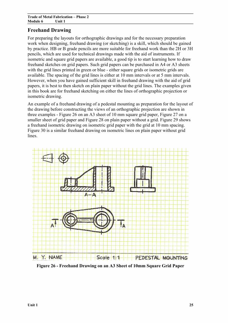
For preparing the layouts for orthographic drawings and for the necessary preparation work when designing, freehand drawing (or sketching) is a skill, which should be gained by practice. HB or B grade pencils are more suitable for freehand work than the 2H or 3H pencils, which are used for technical drawings made with the aid of instruments. If isometric and square grid papers are available, a good tip is to start learning how to draw freehand sketches on grid papers. Such grid papers can be purchased in A4 or A3 sheets with the grid lines printed in green or blue - either square grids or isometric grids are available. The spacing of the grid lines is either at 10 mm intervals or at 5 mm intervals. However, when you have gained sufficient skill in freehand drawing with the aid of grid papers, it is best to then sketch on plain paper without the grid lines. The examples given in this book are for freehand sketching on either the lines of orthographic projection or isometric drawing.
An example of a freehand drawing of a pedestal mounting as preparation for the layout of the drawing before constructing the views of an orthographic projection are shown in three examples - Figure 26 on an A3 sheet of 10 mm square grid paper, Figure 27 on a smaller sheet of grid paper and Figure 28 on plain paper without a grid. Figure 29 shows a freehand isometric drawing on isometric grid paper with the grid at 10 mm spacing. Figure 30 is a similar freehand drawing on isometric lines on plain paper without grid lines.
Figure 26 - Freehand Drawing on an A3 Sheet of 10mm Square Grid Paper
Trade of Metal Fabrication – Phase 2 Module 6 Unit 1
Unit 1 26
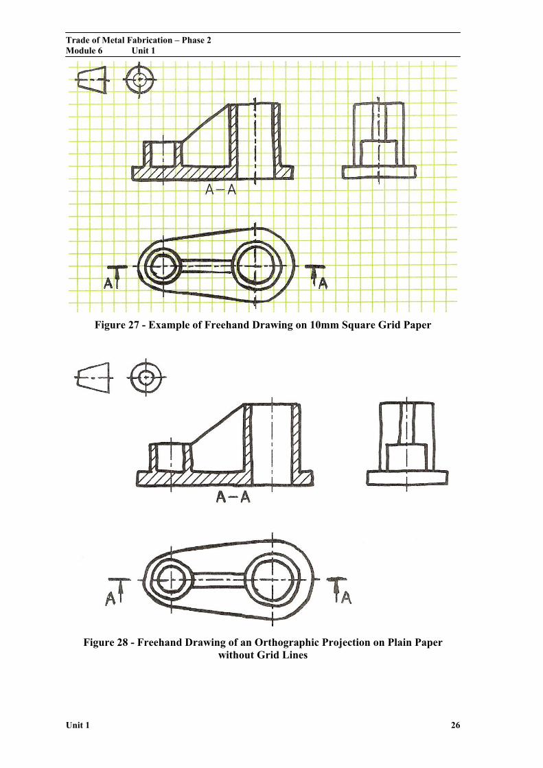
Figure 27 - Example of Freehand Drawing on 10mm Square Grid Paper
Figure 28 - Freehand Drawing of an Orthographic Projection on Plain Paper without Grid Lines
Trade of Metal Fabrication – Phase 2 Module 6 Unit 1
Unit 1 27
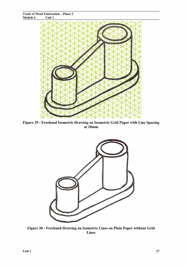
Figure 29 - Freehand Isometric Drawing on Isometric Grid Paper with Line Spacing at 10mm
Figure 30 - Freehand Drawing on Isometric Lines on Plain Paper without Grid Lines
Trade of Metal Fabrication – Phase 2 Module 6 Unit 1
Unit 1 28
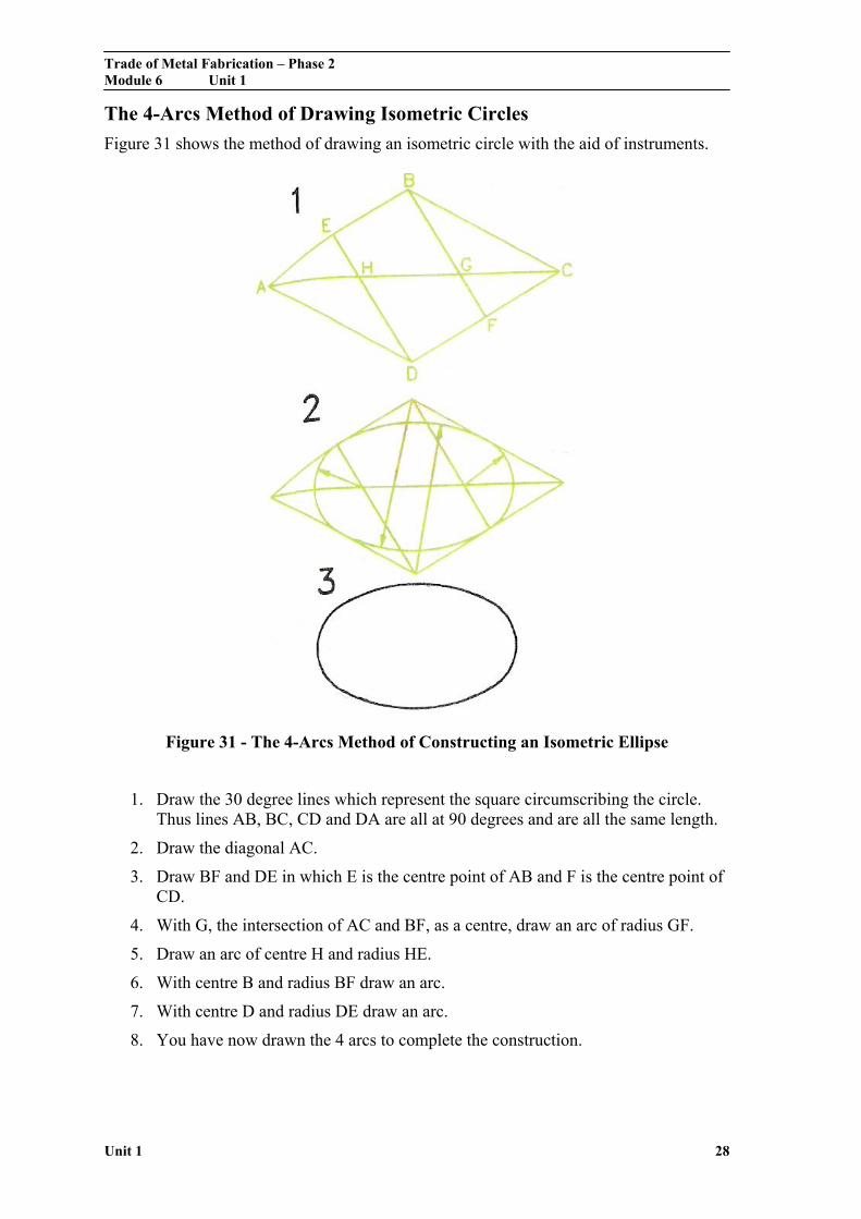
The 4-Arcs Method of Drawing Isometric Circles
Figure 31 shows the method of drawing an isometric circle with the aid of instruments.
Figure 31 - The 4-Arcs Method of Constructing an Isometric Ellipse
1. Draw the 30 degree lines which represent the square circumscribing the circle. Thus lines AB, BC, CD and DA are all at 90 degrees and are all the same length.
2. Draw the diagonal AC.
3. Draw BF and DE in which E is the centre point of AB and F is the centre point of CD.
4. With G, the intersection of AC and BF, as a centre, draw an arc of radius GF.
5. Draw an arc of centre H and radius HE.
6. With centre B and radius BF draw an arc.
7. With centre D and radius DE draw an arc.
8. You have now drawn the 4 arcs to complete the construction.
Trade of Metal Fabrication – Phase 2 Module 6 Unit 1
Unit 1 29
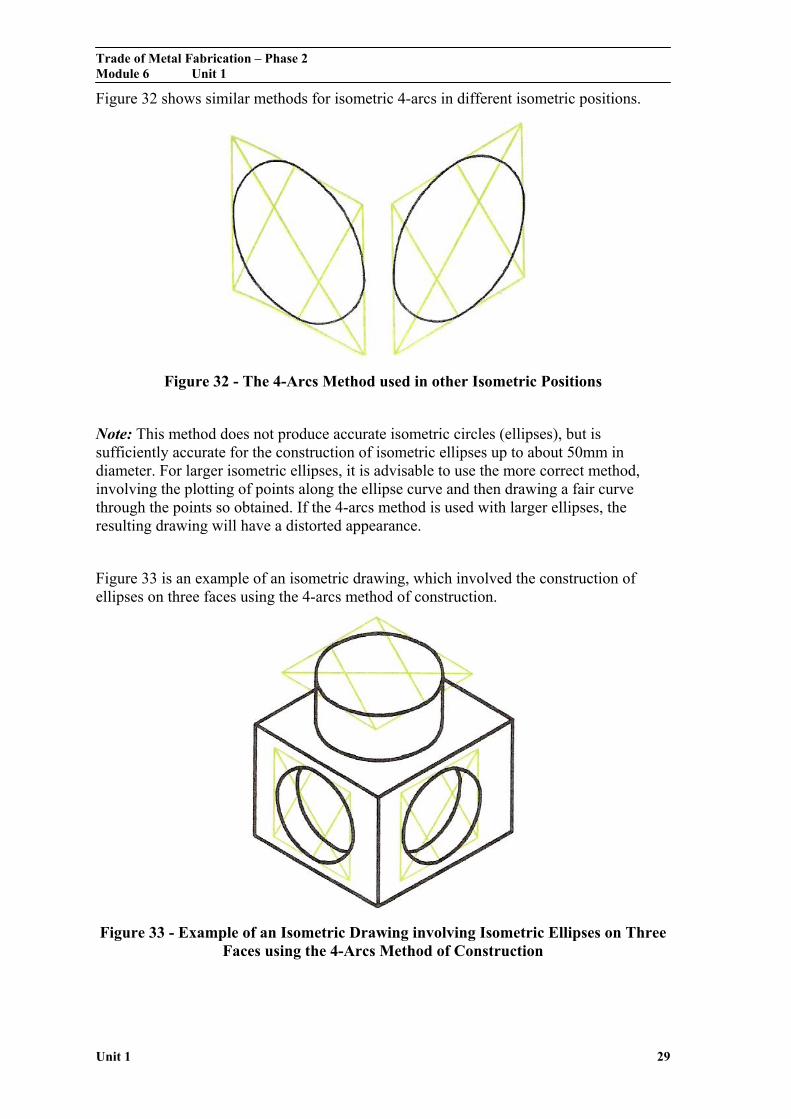
Figure 32 shows similar methods for isometric 4-arcs in different isometric positions.
Figure 32 - The 4-Arcs Method used in other Isometric Positions
Note: This method does not produce accurate isometric circles (ellipses), but is sufficiently accurate for the construction of isometric ellipses up to about 50mm in diameter. For larger isometric ellipses, it is advisable to use the more correct method, involving the plotting of points along the ellipse curve and then drawing a fair curve through the points so obtained. If the 4-arcs method is used with larger ellipses, the resulting drawing will have a distorted appearance.
Figure 33 is an example of an isometric drawing, which involved the construction of ellipses on three faces using the 4-arcs method of construction.
Figure 33 - Example of an Isometric Drawing involving Isometric Ellipses on Three Faces using the 4-Arcs Method of Construction
Trade of Metal Fabrication – Phase 2 Module 6 Unit 1
Unit 1 30
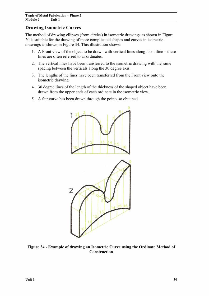
Drawing Isometric Curves
The method of drawing ellipses (from circles) in isometric drawings as shown in Figure 20 is suitable for the drawing of more complicated shapes and curves in isometric drawings as shown in Figure 34. This illustration shows:
1. A Front view of the object to be drawn with vertical lines along its outline – these lines are often referred to as ordinates.
2. The vertical lines have been transferred to the isometric drawing with the same spacing between the verticals along the 30 degree axis.
3. The lengths of the lines have been transferred from the Front view onto the isometric drawing.
4. 30 degree lines of the length of the thickness of the shaped object have been drawn from the upper ends of each ordinate in the isometric view.
5. A fair curve has been drawn through the points so obtained.
Figure 34 - Example of drawing an Isometric Curve using the Ordinate Method of Construction
Trade of Metal Fabrication – Phase 2 Module 6 Unit 1
Unit 1 31
Estimated One and Two-Point Perspective Drawing
If you look carefully at any object, lines along its sides appear as if they are inclined to vanish towards what is known as a Vanishing Point or V.P. this illusion can be readily seen by looking along a pair of straight railway lines. The idea of V.P.s is the basis of the two geometrical methods – one-point (or single-point) and two-point perspective drawing.
Note: True perspective drawing involves a third V.P., but 3-point perspective drawing is beyond the scope of a book of this nature. However, it must be remembered that one-point and two-point perspective drawing do not give true perspective and so may at times appear inaccurate. The two methods do, however, provide an excellent and easy method of drawing very well suited to the preparation of drawings for designs.
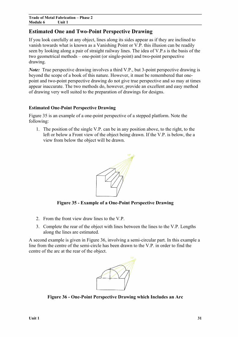
Estimated One-Point Perspective Drawing
Figure 35 is an example of a one-point perspective of a stepped platform. Note the following:
1. The position of the single V.P. can be in any position above, to the right, to the left or below a Front view of the object being drawn. If the V.P. is below, the a view from below the object will be drawn.
Figure 35 - Example of a One-Point Perspective Drawing
2. From the front view draw lines to the V.P.
3. Complete the rear of the object with lines between the lines to the V.P. Lengths along the lines are estimated.
A second example is given in Figure 36, involving a semi-circular part. In this example a line from the centre of the semi-circle has been drawn to the V.P. in order to find the centre of the arc at the rear of the object.
Figure 36 - One-Point Perspective Drawing which Includes an Arc

Trade of Metal Fabrication – Phase 2 Module 6 Unit 1
Unit 1 32
Estimated Two-Point Perspective Drawing
In two-point perspective two V.P.s are positioned. They must be in line with each other horizontally, but can be above or below the object being drawn. The two-point perspective drawing in Figure 37 was drawn as follows:
1. Position the two V.P.s in appropriate positions.
2. Draw a line representing the front edge of the object – this line to be of the same length as the total height of the object.
3. Draw lines from top to bottom of the line to the two V.P.s.
4. Estimate the depth of the object on the right-hand side; draw a vertical line between the two lines to V.P.2.
5. From the intersection of this line with the line to the V.P.2 draw another line to the V.P.1.
6. Continue in this manner to complete the perspective drawing.
Figure 37 - Example of Two-Point Perspective
Note:
The positions of the V.P.s are critical to the appearance of the final drawing, so must be chosen with care to avoid distortion. Some experimenting is advisable. It is only necessary to draw the outline for the perspective to determine whether or not your drawing is going to look as if it is distorted.
The methods of one and two-point perspective are very suitable for freehand drawing, particularly when preparing work for designing.
Trade of Metal Fabrication – Phase 2 Module 6 Unit 1
Unit 1 33
Self Assessment
Questions on Background Notes – Module 6.Unit 1
1. When Spindles and Shafts are inserted into castings/engine blocks, what would
they commonly be slotted into and what material are they normally made from.
2. In this advanced age of C.A.D (Computer Aided Design) what is the purpose of
Technical Drawing?

Trade of Metal Fabrication – Phase 2 Module 6 Unit 1
Unit 1 34
3. Briefly explain Isometric Drawing and what Degree Set-Square would you use?

Trade of Metal Fabrication – Phase 2 Module 6 Unit 1
Unit 1 35
Answers to Questions 1-3. Module 6. Unit 1
1.
Bearings and Brushings:
Spindles and shafts in machines run in bearings, of which there are
many different types. A steel spindle can run in a hole in cast iron
without any special type of bearing. The steel spindle is usually case
hardened - a thin skin of the spindle has extra carbon added by heat
treatment and is then hardened.
Although spindles running directly in holes in cast iron are reasonably
satisfactory, a better bearing is formed when a bush is inserted between
the spindle and cast iron. The bush is made of materials such as phosphor
bronze or an alloy known as white metal.
Figure 1: Bush and its Lubricating Hole.

Trade of Metal Fabrication – Phase 2 Module 6 Unit 1
Unit 1 36
2.
3.
Isometric Drawing:
Isometric drawing is a form of pictorial drawing based on lines at
30 degrees from the horizontal. Figure 2 shows the basic idea when
making an isometric drawing of a rectangular prism. Vertical lines are
drawn with the aid of the right angle of a set square; lines at 30 degrees
are drawn with the aid of a 30,60 set square.
Figure 2: Isometric Drawing of a Rectangular Prism:
Technical Drawing:
Even the most skilled computer expert working as a draughtsman
with a CAD system must have a good technical drawing background.
Without a good knowledge of the practice of technical drawing methods
learned 'at the drawing board', a CAD operator cannot produce technical
drawings with his/her equipment. It is only by practising with the aid of
drawing instruments that computer drawing skills can be gained.
A good practical knowledge of plane and solid geometry, an under-
standing of the theory of orthographic projection, the use of good
standard drawing conventions can only be learned by constant practice
'at the drawing board'. First learn how to produce good quality
technical drawings 'by hand', then learn how to produce them with CAD.
Trade of Metal Fabrication – Phase 2 Module 6 Unit 1
Unit 1 37
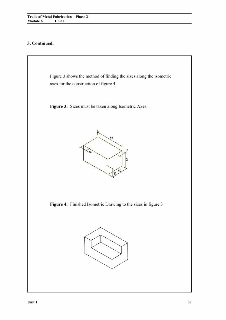
3. Continued.
Figure 3 shows the method of finding the sizes along the isometric
axes for the construction of figure 4.
Figure 3: Sizes must be taken along Isometric Axes.
Figure 4: Finished Isometric Drawing to the sizes in figure 3
Trade of Metal Fabrication – Phase 2 Module 6 Unit 1
Unit 1 38
Index
B
Bearings Ball and Roller Bearings, 11
E
Engineering Drawing, 10 Bearings, 10 Bevel Gears, 15 Introduction, 10 Radial Cams, 16 Spur Gears, 13
Estimated One and Two-Point Perspective Drawing Estimated One-Point Perspective
Drawing, 31 Estimated Two-Point Perspective
Drawing, 32 Exploded Isometric Drawing
A Simple Exploded Isometric Drawing, 24
An Exploded Isometric Drawing, 24
P
Pictorial Drawing, 21
Constructing Isometric Curves, 22 Drawing Isometric Curves, 30 Estimated One and Two-Point
Perspective Drawing, 31 Exploded Isometric Drawing, 24 Freehand Drawing, 25 Introduction, 21 Isometric Drawing, 21 The 4-Arcs Method of Drawing
Isometric Circles, 28 Purpose of Technical Drawing, 20
Why Then Learn Technical Drawing?, 20
S
Self Assessment, 33
T
Technical Drawing and Design, 18 Introduction, 18 The Place of Technical Drawing in
Designing, 20