tracvision a5 installation guide - abt electronics · pdf filetracvision a5 installation guide...
TRANSCRIPT


1
TracVision A5 Installation Guide – ADDENDUM
54-0208-01 Addendum to Rev. C
TracVision A5 InstallationGuide AddendumECO #6864The following information applies to Revision C of the TracVision A5 Installation Guide (KVH Part Number 54-0208-01).
The note on page 2.6 incorrectly states that a section of rubber,neoprene, or foam should be attached to the base of the antennaif there is less than 1" of space between the antenna and the roof.KVH no longer recommends this action because it may cause thecenter of the antenna to compress and possibly damage theantenna’s internal parts.
The note on page 2.6 (Step 6) has been changed as shown below:
6. With the cushions installed in the brackets, thebottom of the antenna should rest higher than 1"above the vehicle’s roof. If the antenna’s base isless than 1" from the roof, you will need to add aspacer under each bracket to raise the antennahigher off the crossbars.
If spacers are needed, follow the steps below toinstall a spacer under each bracket:
a. Remove the #8-32 x 3⁄8" screws and washers securing the factory-installed plastic spacer to the metal bracket.
b. Insert a second spacer from the kitpack between the original spacer (which holds the rubber cushions) and the bracket. Secure both spacers to the bracket using the #8-32 x 1" screws supplied in the kitpack and the original washers that you removed in Step a.
Bracket
New Spacer
Flat Washer
Lock Washer
#8-32 x 1" Screw
Factory-installed Spacer
Adding a Second Spacer to the Bracket
If, after you have installed the spacers, there is lessthan 1⁄2" of space between the antenna and the roof,KVH recommends that you either use the optionalroof mount kit or replace the roof rack with anaftermarket model that offers greater clearance. If theantenna is mounted too low, it may strike the roofwhen the vehicle is in motion.

1
TracVision A5 Installation Guide – ADDENDUM
54-0208-01 Addendum to Rev. C
TracVision A5 InstallationGuide AddendumECO #6822The following information applies to Revision C of the TracVision A5 Installation Guide (KVH Part Number 54-0208-01).
The kitpack packaged with your TracVision A5 system does notcontain 16 tapered rubber cushions (24-0174), as described in theInstallation Guide. These cushions are unnecessary for a properinstallation. The 16 level rubber cushions (24-0173) supplied inthe kitpack should be used in all roof rack installations.
Step 5 of Section 2-1, “Mounting the Antenna to the Vehicle’s Roof,”has been changed to remove references to the tapered cushions:
5. Each bracket and retaining block (which you willattach to the bracket later) contains several pairs ofpegs. These pegs allow you to place the fourrubber cushions in different positions to best fitthe vehicle’s particular style of crossbars.
Try out the various cushion positions until youfind the best fit for your installation.
The more surface area of the cushions pressing againstthe top and bottom of the crossbar, the better the fit.
Level Cushion - Supplied
Tapered Cushion - Not Supplied
Bracket
Roof Rack Crossbar
Rubber Cushions
Rubber Cushions
Retaining Block
Pegs
Positioning Rubber Cushions for Best Fit

1
TracVision A5 Installation Guide – ADDENDUM
54-0208-01 Addendum to Rev. C
TracVision A5 InstallationGuide AddendumECO #6705The following information applies to Revision C of the TracVision A5 Installation Guide (KVH Part Number 54-0208-01).
When you start up the TracVision antenna, do not move thevehicle for 20 seconds. This allows the antenna gyros to initializeproperly, ensuring optimum satellite tracking performance.
4-3 Testing the SystemNow all you need to do is turn the system on and ensureeverything works properly. Follow the steps below to turn on theTracVision A5 system and verify proper operation.
1. Ensure that the antenna has a clear view of thesatellite. The antenna requires an unobstructedview of the southern sky to receive satellite TVsignals. Trees, buildings, highway overpasses, etc.,can block satellite signals. Heavy rain or snowmay also interrupt satellite signals. For completedetails about satellite reception requirements, referto Section 1.3, “Receiving Satellite TV Signals,” in theTracVision A5 User’s Guide.
2. Apply vehicle power and turn on the vehicle’sentertainment system.
3. Turn on the TracVision A5 receiver’s front panelpower switch. The switch’s light illuminates andthe receiver beeps twice.
4. Wait 30 seconds. The antenna should then poweroff and the receiver should beep once.
Since the TracVision antenna requires an unobstructedview of the southern sky to receive satellite signals, thesystem will not work when the vehicle is in a garage.
Receiver Front Panel Power Switch
Power Switch

2
5. Press the remote control’s SAT button. The buttonshould blink red. If it doesn’t, check the remotecontrol’s batteries.
6. Now press the POWER button. The receiver beepstwice to indicate that power is again applied to theantenna.
7. Do not move the vehicle for 20 seconds. Thisallows the antenna gyros to initialize properly.
8. Verify that the following appears on the TV(s):
The TracVision antenna searches for and locksonto the satellite. The receiver then startsdownloading the program guide and thefollowing message appears:
This process may take up to 60 seconds. Once theprogram guide has loaded, a DIRECTVprogramming channel appears. Only the DIRECTVpreview channels (such as channels 100 and 201) areviewable until the user activates the receiver.
Installation
If your satellite dish is ready for DIRECTV®
service, please wait until yourAdvanced Program Guide™ is prepared.
Searching for satellite signal...
Installation
If your satellite dish is ready for DIRECTV®
service, please wait until yourAdvanced Program Guide™ is prepared.
Acquiring guide data...
CHVOL
PWR
DVD VCR AUX TV SAT
GUIDE
MENU
INFO CLEAR
TURBOFAV
SELECT
MUTE CHPREV
PAGE
ONELINE GUIDE

1
TracVision A5 Installation Guide – ADDENDUM
54-0208-01 Addendum to Rev. C
TracVision A5 InstallationGuide AddendumECO #6670The following information applies to Revision C of the TracVision A5 Installation Guide (KVH Part Number 54-0208-01).
Recording the Antenna Serial NumberBefore installing the system, peel off the extra antenna serialnumber label (taped to the antenna) and affix it in theappropriate box on the activation information card that isattached to the receiver. In addition, enter the antenna serialnumber in the appropriate box on the first page of the TracVisionA5 User’s Guide. The user will need this number to activate thereceiver, and the receiver must be activated in order to watchsatellite TV via the TracVision A5 system.

1
TracVision A5 Installation Guide – ADDENDUM
54-0208-01 Addendum to Rev. C
TracVision A5 InstallationGuide AddendumECO #6669The following information applies to Revision C of the TracVision A5 Installation Guide (KVH Part Number 54-0208-01).
Shipping RestraintsTo better prevent shipping damage, wire rope is now usedinstead of plastic tie-wraps to secure the antenna mechanism inplace. To remove these restraints, you will need to use heavy-duty wire cutters to snip the wire.
1 2
3
4
6
5
Do not remove the restraints until you have attached thefour mounting brackets to the antenna’s base and areready to place the antenna onto the vehicle. See Section 2-1, “Mounting the Antenna to the Vehicle’s Roof.”
Shipping Restraint Locations

1
TracVision A5 Installation Guide – ADDENDUM
54-0208-01 Addendum to Rev. C
TracVision A5 InstallationGuide AddendumECO #6516The following information applies to Revision C of the TracVision A5 Installation Guide (KVH Part Number 54-0208-01).
The RF-to-IR converter described in the manual has beenreplaced with a new RF converter. This new component receivesRF signals from the remote control and converts them directly todigital signals, which the receiver can understand.
The following pages show the resulting changes to the TracVision A5Installation Guide.
New RF Converter

2
1-2 System OverviewA complete satellite TV system includes the TracVision A5antenna and receiver connected to the vehicle’s audio/videoentertainment system. The remote control and RF converterallow the user to operate the system from anywhere in thevehicle.
(RF = Radio Frequency)
RF Converter
The RF converter receives radio frequency commands from theremote control, converts them to digital signals, and sends themto the receiver for processing.
VehicleAudio/Video System
TracVision A5 Antenna
Purchased Separately
Receiver
Remote ControlCH
VOL
DVD
VCR
AUX
TV
SAT
HRMC-9
GUIDE
MENU
INFO
CLEAR
TURBO
FAVSELECT
MUTE
CH
PREV
PROG
SEARCH
AUDIO
VIDEO
1
2
3
4
5
6
7
8
90
INPUT
REW
PLAY
FF
REC
STOP
PAUSE
PA
GE
ONELINEG
UID
E
PWR
DIRECTOR
RF Converter
Vehicle Power(10-16 VDC)
TracVision A5 System Diagram (Typical Installation)

1-3 Materials ProvidedThe table of provided components has been updated to list thenew RF converter.
Component KVH Part #
Packaged in antenna box:
Antenna unit 02-1289-01
Packaged in receiver box:
Receiver 02-1287-01
RF converter 02-1344
Remote control 19-0335
TracVision A5 User’s Guide 54-0208
TracVision A5 Installation Guide 54-0208-01
1-4 Planning the InstallationKitpack Contents
The RF-to-IR converter cable (part # 32-0773) has been removed fromthe kitpack. It is no longer needed, since the new RF converter comeswith an attached cable.
3
TracVision A5 Installation Guide – ADDENDUM
54-0208-01 Addendum to Rev. C

3-1 Wiring the ReceiverThe receiver rear panel has been modified to accept the new RFconverter cable. The diagram below shows the new receiverwiring.
Connecting the RF Converter Cable
To connect the RF converter cable, follow the steps below.
1. Connect the RF converter cable to the “RF RemoteInput” jack on the receiver’s rear panel.
2. Place the RF converter at least three feet awayfrom the receiver’s location.
Connecting an Existing IR Input (Optional)
The optional vehicle IR adapter cable is no longer available. Usethe new RF converter in all installations.
4
TracVision A5 Wiring Diagram
Antenna
For detailed system wiring instructions, refer to the TracVision A5 Installation Guide.
RF Converter
Receiver
Vehicle Roof
CAUTION
KVH® is a registered trademark of KVH Industries, Inc. HUGHES™ is a trademark of Hughes Electronics Corporation.
This device complies with Part 15J of the FCC rules. Operation is subject to the following two conditions: (1) This device must not cause harmful interference, and (2) This device must accept any interference received, including interference that may cause undesired operation.
Product Warranty void if outer casing removed.
VEHICLE POWER(10-16 VDC)
VHFANTENNA IN
S-VIDEO
TO KVHANTENNA
TO VIDEO
TruSurround, SRS and symbol are trademarks of SRS Labs, Inc.
SATELLITE IN
AUDIO R AUDIO L VIDEO
Service/Maintenance
Only
DC Power
Ground
To VehicleAudio
To Vehicle Video(Option 1)To Vehicle Video(Option 1)
To Vehicle Video(Option 3)
To Vehicle Video(Option 2)
To VHF Antenna(Optional)
Vehicle Power(10-16 VDC)
Fuse
RF REMOTEINPUT
OUT TO TVCOMPOSITE VIDEO
TO IRD SATELLITE IN
DIAGNOSTIC PORT 1 DIAGNOSTIC PORT 2
The RF converter must be placed at least three feet awayfrom the receiver. Placing the RF converter closer to thereceiver may result in interference, causing the remotecontrol to operate intermittently or not at all.

1
TracVision A5 Installation Guide – ADDENDUM
54-0208-01 Addendum to Rev. C
TracVision A5 InstallationGuide AddendumECO #6423The following information applies to Revision C of the TracVision A5 Installation Guide (KVH Part Number 54-0208-01).
Rubber Cushions All Black
All of the rubber cushions provided with the TracVision A5 areblack in color. The level rubber cushions (described in step 5 ofSection 2-1, “Mounting the Antenna to the Vehicle’s Roof,” on page 2.5) are black, not gray, in color.
New Antenna Mounting Hardware
The 1⁄4"-20 x 21⁄2" tamper-resistant screws provided in theTracVision A5 kitpack differ from those described in the manual.They have a Snake Eyes® head instead of a TORX® head. Thekitpack also includes a Snake Eyes bit for tightening these screws.New part numbers are noted below.
Part Part # Qty.
1⁄4"-20 x 21⁄2" Snake Eyes screws 14-0373-40 8
Tamper-proof Snake Eyes bit 14-0379 1
The Snake Eyes screws are only necessary if you need to install aspacer underneath each antenna mounting bracket, as describedin step 6 of Section 2-1, “Mounting the Antenna to the Vehicle’sRoof,” on page 2.6. Steps 8 and 9 of Section 2-1 are superseded bythe information on the following pages.
Snake EyesScrew Head

2
8. Insert the appropriate tamper-resistant flat-headscrews into each bracket’s swivel nuts:
If you DID NOT install spacers in Step 6:Insert 1⁄4"-20 x 2" TORX screws into the bracket’sswivel nuts.
If you DID install spacers in Step 6:Insert 1⁄4"-20 x 21⁄2" Snake Eyes screws into thebracket’s swivel nuts.
Be sure to use the tamper-resistant hardware provided inthe kitpack.
Bracket
Bracket Screws(Tamper-proof)
Cover
Roof Rack Crossbar
Retaining Block
Rubber Cushions
Swivel Nuts
Swivel Nuts
Rubber Cushions
Flat Washers
Lock Nuts
Securing the Brackets to the Crossbars

9. At each bracket, position a retaining blockunderneath the crossbar and insert two swivelnuts, 1⁄4" flat washers, and lock nuts into the captiveholes from below. While holding this hardware inplace, screw the bracket’s screws into the retainingblock’s swivel nuts, washers, and lock nuts using a1⁄4" driver and the supplied T27 TORX bit or SnakeEyes bit, as required. After securing all fourbrackets to the crossbar, verify that all cushions arepressed firmly against the crossbar, providing asolid grip. Also check to make sure that all eightscrews have engaged the nylon inserts in the locknuts.
3
TracVision A5 Installation Guide – ADDENDUM
54-0208-01 Addendum to Rev. C
Securing the Tamper-proof Screws
Tamper-proofScrews
Retaining Block
Retaining Block
Swivel Nut
Flat Washer
Lock Nut

TracVision A5Installation GuideThe TracVision A5 is a state-of-the-art, activelystabilized antenna system that delivers live satelliteTV to a vehicle, even while the vehicle is moving.
This manual provides detailed instructions on theproper installation of the TracVision A5 system.Complete instructions on how to use the system areprovided in the TracVision A5 User’s Guide.
Welcome Page
This product must NOT be connected toany active monitor that is visible to thevehicle’s driver while the vehicle is inmotion. This product is intended for rear-seat entertainment only.
KVH Part # 54-0208-01 Rev . C
© 2003, KVH Industries, Inc.
Patents Pending

Trademarks
KVH® and TracVision® are registered trademarks of KVH Industries, Inc.
DIRECTV® and the Cyclone Design logo, DIRECTV INTERACTIVE, TOTALCHOICE, DIRECTV HOME SERVICES, and DIRECT TICKET aretrademarks of DIRECTV, Inc., a unit of Hughes Electronics Corp. FREEVIEWis a registered trademark of Hughes Electronics Corporation. All trademarks,marks, names, or product names referenced in this publication are theproperty of their respective owners, and KVH neither endorses nor otherwisesponsors any such products or services referred to herein.
Dolby Laboratories Information – Manufactured under license from DolbyLaboratories. “Dolby,” “Pro Logic,” and the double-D symbol are trademarks ofDolby Laboratories.
Macrovision® Information – Macrovision is a registered trademark ofMacrovision Corporation. This device incorporates an anticopy processtechnology that is protected by U.S. patents 4,631,603; 4,577,216; 4,819,098;and other intellectual property rights. The anticopy process is licensed fornoncommercial, home use only. Reverse engineering or disassembly isprohibited.
StarSight® Information – StarSight features licensed under one or more of thefollowing patents: 4,706,121; 5,151,789; 5,353,121; 5,353,277; 5,479,266;5,479,268; and 5,532,754. Use rights reserved.
TruSurround™ Information – TruSurround and the symbol aretrademarks of SRS Labs, Inc. TruSurround technology is incorporated underlicense from SRS Labs, Inc.
WINK® Information – WINK and the symbol are registered trademarks ofWINK Communications, Inc.
ENERGYSTAR® Information – ENERGYSTAR and the ENERGYSTARcertification mark are registered US marks.
TORX® is a registered trademark of Camcar/Textron, Inc.
Snap-N-Seal® is a registered trademark of Thomas & Betts Corporation.
Hummer® is a registered trademark of GM Corporation.
Software contained in the TracVision A5 receiver and referenced in thismanual is copyright ©1995-2003 by Hughes Network Systems, Inc., a whollyowned subsidiary of Hughes Electronics Corporation. Some features arepatent pending. WatchWizard, PreSelect, TurboTune, and OneLine Guide aretrademarks of Hughes Network Systems. “NFL,” the NFL Shield, and “NFLSUNDAY TICKET” are registered trademarks of the National Football Leagueand its affiliates. “NHL,” the NHL Shield, and “NHL CENTER ICE” areregistered trademarks of the National Hockey League. “MLB,” “MLB EXTRAINNINGS,” “Major League Baseball,” and the Major League Baseballsilhouetted batter logo are service marks of Major League BaseballProperties, Inc. Major League Baseball trademarks and copyright are usedwith permission of Major League Baseball Properties, Inc. All othertrademarks and service marks are the property of their respective owners.
Disclaimer
Every effort has been made to ensure the correctness and completeness ofthe material in this document. No company shall be liable for errorscontained herein. The information in this document is subject to changewithout notice. No warranty of any kind is made with regard to this material,including, but not limited to, the implied warranties of merchantability andfitness for a particular purpose.
Note on recording programming
Most television programs and films are copyrighted. This means thatsomeone has legal rights governing the reproduction and distribution of thismaterial. In certain circumstances, copyright law may apply to private tapingof copyrighted materials. In most cases, it is permissible to record for yourpersonal use, as long as you do not sell the material. You must actresponsibly in this area–check into the matter if you are unsure.
Some pay-per-view programs may be licensed from producers as “view-only”programs. These are copyrighted programs, and may not be copied orreproduced for any purpose without the express written permission of thecopyright owner.
54-0208-01ii
TracVision A5 Installation Guide

Important Safety Instructions - PleaseRead Carefully
For your safety and protection, read this entireInstallation Guide before you install the TracVisionsystem. In particular, read this safety section carefully.
Heed Cautions – Be sure to follow all cautions on theproduct and in the installation instructions. Cautionsare indicated by a or icon.
Follow Instructions – Be sure to follow all installationinstructions as detailed in this manual.
The following caution appears on the back of thereceiver:
Do not open the receiver’s cover. Opening orremoving the cover may expose you to dangerousvoltage.
To reduce the risk of fire orelectrical shock, do NOT expose thereceiver to rain or moisture and doNOT insert any objects into thereceiver’s ventilation openings.
54-0208-01iii
Important Safety Instructions
Avoid Driver DistractionIt is dangerous to watch televisionor operate the remote controlwhile you are driving a vehicle.The TracVision A5 is designed
specifically to provide entertainment to vehiclepassengers and should never be connected toactive video screens visible to the vehicle driverwhile the vehicle is in motion. Failure by thedriver of a vehicle equipped with a TracVision A5 to pay full attention to traffic androad conditions could result in an accident orcollision with personal injury or death resulting.
WARNING!
CAUTION
CAUTION

Federal Communications Commission (FCC)Regulatory Information
Declaration of Conformity – Standards to which Conformity is declared:FCC Part 15
This device complies with Part 15 of the FCC Rules. Operation is subjectto the following two conditions: (1) this device may not cause harmfulinterference, and (2) this device must accept any interference received,including interference that may cause undesired operation.
Responsible Party’s Name: KVH Industries, Inc.
Address: 50 Enterprise Center, Middletown, RI 02842
Telephone: 1-401-847-3327
Trade Name: KVH
Type of Equipment: Satellite Receiver
Model Number: TracVision A5
Federal Communications Commission (FCC) –This equipment complieswith Part 15 of the FCC rules.
Part 15 Compliance – This equipment has been tested and found to complywith the limits for a Class B digital device, pursuant to Part 15 of the FCCrules. These limits are designed to provide reasonable protection againstharmful interference in a vehicle installation. This equipment generates, uses,and can radiate radio frequency energy and, if not installed and used inaccordance with the instructions, may cause harmful interference to radiocommunications.
However there is no guarantee that interference will not occur in a particularinstallation. If this equipment does cause harmful interference to radio ortelevision reception, which can be determined by removing and applyingpower to the equipment, the user is encouraged to try to correct theinterference by one or more of the following measures:
• Increase the separation between the equipment and the receiver.
• Connect the equipment on a circuit different from that to which thereceiver is connected.
• Consult the dealer or an experienced auto electronics technician for help.
The user may find the following booklet, prepared by the FederalCommunications Commission, helpful: “How to Identify and Resolve Radioand TV Interference Problems.” This booklet is available from the U.S.Government Printing Office, Washington, DC.
To meet FCC requirements, only components certified to comply with ClassB limits may be attached to this device. Operation with noncertifiedperipherals is likely to result in interference to radio and TV reception.
To meet FCC requirements, shielded cables are required to connect thedevice to another Class B certified device.
54-0208-01iv
TracVision A5 Installation Guide

Technical SupportIf you need technical assistance when installing theTracVision A5, please call KVH Technical Support:
Phone: (401) 847-3327
E-mail: [email protected]
Internet: www.kvh.com/help
54-0208-01v
Technical Support
Send Us Your Comments About This ManualIf you have any comments regarding this manual,please e-mail them to [email protected]. Yourfeedback is greatly appreciated!
Table of Contents1 Getting Started . . . . . . . . . . . . . . . . .1.1
1-1 Using this Manual . . . . . . . . . . . . . . .1.3
1-2 System Overview . . . . . . . . . . . . . . . .1.4
1-3 Materials Provided . . . . . . . . . . . . . . .1.6
1-4 Planning the Installation . . . . . . . . . . .1.6
2 Installing the Antenna . . . . . . . . . . . .2.1
2-1 Mounting the Antenna to theVehicle’s Roof . . . . . . . . . . . . . . . . . .2.3
2-2 Connecting the Antenna Cable . . . . .2.9
3 Installing the Receiver . . . . . . . . . . . .3.1
3-1 Wiring the Receiver . . . . . . . . . . . . . .3.3
3-2 Mounting the Receiver . . . . . . . . . . .3.12
4 Completing the Installation . . . . . . . . .4.1
4-1 Installing the Remote ControlBatteries . . . . . . . . . . . . . . . . . . . . . .4.3
4-2 Post-installation Checklist . . . . . . . . .4.4
4-3 Testing the System . . . . . . . . . . . . . .4.6
4-4 Activating the Receiver . . . . . . . . . . .4.7
4-5 Programming the Remote Controlto Operate Other Components(Optional) . . . . . . . . . . . . . . . . . . . . .4.8
Appendices . . . . . . . . . . . . . . . . . . . . . .A.1
A System Specifications . . . . . . . . . . . .A.3
B Manufacturer Device Codes . . . . . . . .A.5
Warranty . . . . . . . . . . . . . . . . . . . . . . . . .A.17
54-0208-01vii
Table of Contents

54-0208-011.1
Getting Started
1 Getting StartedThis section provides a basic overview of this manual and theTracVision A5 system. It also lists the components supplied withthe system.
Contents1-1 Using this Manual . . . . . . . . . . . . . . . . . . . . . . . . . . . .1.3
1-2 System Overview . . . . . . . . . . . . . . . . . . . . . . . . . . . . .1.4
1-3 Materials Provided . . . . . . . . . . . . . . . . . . . . . . . . . . . .1.6
1-4 Planning the Installation . . . . . . . . . . . . . . . . . . . . . . .1.6

1-1 Using this Manual
This manual provides complete instructions forinstalling the TracVision A5 system. Throughout thismanual, important information is marked for yourattention by the following icons:
Who Should Install the TracVision A5 SystemKVH strongly recommends that a KVH-authorizedtechnician and an assistant install the TracVision A5system. Installers should have experience installingelectronic equipment on a vehicle and haveknowledge about satellite television.
54-0208-011.3
Getting Started
� ������� �� ��� ����� ��� �� ��� �� ������ �� ���� ��� ���� �������� ���������� �� ������ ��������� ����� ��� �� ���� �������
�� ���� �� ������� ��������������� ��� ������� ����� ���� � ����� �� ����� � ����
�� ��� �� � ����� ����� �� ���������� ��� �� � ����� ��� � �� ���� �� ����� ��� ��� ����� � �� �����
��������� ���� ��������������� �� ��������������� ������� �� �� � ������
KVH is not liable for damage (or relatedexpenses) caused by improper installation.
Do NOT attempt to install the antenna byyourself. Two people are needed to lift theantenna onto the vehicle’s roof.

1-2 System OverviewA complete satellite TV system includes theTracVision A5 antenna and receiver connected to thevehicle’s audio/video entertainment system. TheRF/IR remote control and RF-to-IR converter allowsthe user to operate the system from anywhere in thevehicle.
(RF = Radio frequency; IR = Infrared)
54-0208-011.4
TracVision A5 Installation Guide
VehicleAudio/Video System
TracVision A5 Antenna
Purchased Separately
Receiver
RF/IR Remote ControlCH
VOL
DVD
VCR
AUX
TV
SAT
HRMC-9
GUIDE
MENU
INFO
CLEAR
TURBO
FAV
SELECT
MUTE
CH
PREV
PROG
SEARCH
AUDIOVIDEO
1
2
3
4
5
6
7
8
90
INPUT
REW
PLAY
FF
REC
STOP
PAUSE
PA
GE
ONELINE
GU
IDE
PWR
DIRECTOR
RF-to-IR Converter
Vehicle Power(12 VDC)
TracVision A5 System Diagram (Typical Installation)

System ComponentsThe TracVision A5 includes the followingcomponents:
Antenna Unit
The antenna unit, mounted onto the vehicle’s roofrack, houses the phased array, positioningmechanisms, low noise block (LNB), and controlelements within a weathertight radome. A singlecable connects the antenna to the receiver inside thevehicle.
Receiver
The receiver, mountedinside the vehicle,decodes satellite signalsfrom the antenna unitand sends the signals tothe vehicle’s audio/video system. It also suppliespower to the TracVision antenna.
Remote Control
The backlit wireless RF/IR remotecontrol allows the user to control thesystem from anywhere in the vehicle.The remote does not need to bepointed directly at the receiver for thesignal to be received.
RF-to-IR Converter
The RF-to-IR converter receivesradio frequency (RF) commandsfrom the remote control, convertsthem to infrared (IR) signals, andsends them to the receiver forprocessing.
54-0208-011.5
Getting Started

1-3 Materials Provided
The following components are provided with theTracVision A5 system.
Component KVH Part #
Packaged in antenna box:
Antenna unit 02-1289-01
Packaged in receiver box:
Receiver 02-1287-01
RF-to-IR converter 02-1293
Remote control 19-0335
TracVision A5 User’s Guide 54-0208
TracVision A5 Installation Guide 54-0208-01
Initial InspectionCarefully remove the components from theirpackaging and examine to ensure that nothing wasdamaged in shipment. Save the packaging in case youneed to ship the system someday.
1-4 Planning the Installation
Materials and Equipment RequiredTo install the TracVision system, you will need thefollowing tools and materials:
• 1⁄4" driver
• Phillips and flat-head screwdrivers
• Stepladder
• 7⁄16" open-end wrench
• Wire cutters
If routing the antenna cable through the roof:
• Light hammer and center punch
• Drill and 5⁄32" bit
• 1⁄2" hole saw
• Silicone sealant or RTV
If cutting the antenna cable to length:
• LRC/Augat IT1000 crimp tool (available fromKVH; call (401) 847-3327 to order)
54-0208-011.6
TracVision A5 Installation Guide

Kitpack ContentsThe kitpack that was packaged with your systemcontains various hardware and other materials thatyou will need to complete the TracVision A5installation. Ensure that the kitpack contains all of theitems listed below.
Part Part # Qty.
Antenna brackets 20-0947 4
Plastic clamp spacers 30-0180 4
Retaining blocks 30-0181 4
Clamp covers (front) 30-0190 2
Clamp covers (rear) 30-0191 2
Swivel nuts 20-0980 16
Hex lock nuts 14-0065-25 8
1⁄4" flat washers 14-0132-08 8
Rubber cushions (black) 24-0174 16
Rubber cushions (gray) 24-0173 16
Part Part # Qty.
#8-32 x 1" screws 14-0041-08 8
Tamper-proof TORX® T27 bit 14-0378 1
1⁄4"-20 x 1" TORX screws 14-0361-16 12
1⁄4"-20 x 2" TORX screws 14-0363-32 8
1⁄4"-20 x 21⁄2" TORX screws 14-0363-40 8
Receiver brackets 20-0931 2
#8-32 x 5⁄16" screws 14-0041-65 4
#6 x 1⁄2" self-drilling screws 14-0357-08 6
#8 washers 14-0226-08 4
DC power cable 32-0760 1
Antenna cable, 20 ft. 32-0778-20 1
Snap-N-Seal F-connector 23-0170 1
Audio/video cables 32-0763 1
RF-to-IR converter cable 32-0773 1
Backing plate 20-0983 1
#6-32 x 5⁄8" screws 14-0224-10 4
54-0208-011.7
Getting Started
Kitpack Contents

Choosing the Receiver LocationNow that you’ve got everything you need to installthe TracVision A5, locate a suitable location formounting the receiver. The receiver should beinstalled in a secure, dry location away from any heatsources. Also be sure the location will allow enoughopen space (at least 2" around) for ventilation andcable connections. Suggested locations are under aseat or inside the trunk.
Recording the Antenna Serial NumberBefore installing the antenna, peel off the extra serialnumber label (taped to the antenna) and affix it in theappropriate box on the first page of the TracVision A5User’s Guide.
54-0208-011.8
TracVision A5 Installation Guide
Part Part # Qty.
Tie-wraps 22-0041 9
Small protective caps 24-0128 2
Large protective caps 24-0177 2
AAA batteries 15-0015 2
Kitpack Contents (continued)
The antenna mounting brackets packagedwith the TracVision A5 fit the vast majority ofroof rack models. If the vehicle’s roof rackcrossbars are oversized (such as thoseinstalled on Hummers®), please call KVH at(401) 847-3327 to order a specialinstallation kit.
Be sure to affix the extra antenna serialnumber label on the first page of theTracVision A5 User’s Guide. The user willneed this number to activate the receiver,and the receiver must be activated in orderto watch satellite TV via the TracVision A5system. See Section 4-4, “Activating theReceiver” on page 4.7 for details.

54-0208-012.1
Installing the Antenna
2 Installing the AntennaThis section explains how to mount the antenna to the vehicle’sroof rack. It also explains how to connect and route the antennacable.
Contents2-1 Mounting the Antenna to the Vehicle’s Roof . . . . . . . . .2.3
2-2 Connecting the Antenna Cable . . . . . . . . . . . . . . . . . . .2.9

54-0208-012.3
Installing the Antenna
2-1 Mounting the Antenna to theVehicle’s Roof
The TracVision antenna mounts onto the vehicle’sroof rack by clamping onto the crossbars. To mountthe antenna, follow the steps below.
1. Position the roof rack’s crossbars 351⁄2" apart,measured center-to-center. Ensure that thecrossbars are securely fastened to the vehicle.
2. Underneath each of the antenna’sfour corners, attach a suppliedmounting bracket using three 1⁄4"-20 x 1" button-head TORXscrews supplied in the kitpack.Use a 1⁄4" driver and the suppliedT27 TORX bit to tighten thescrews; do not overtighten.
Be sure the roof rack’s crossbars aresecured in place and are sturdy enough tosupport the 48 lb antenna.
Roof Rack Crossbars
1/4"-20 x 1" Button-headTORX Screws
Mounting Bracket
Antenna
Attaching Brackets to the Antenna Base
TORX Screw Head
Crossbars351⁄2" apart

54-0208-012.4
TracVision A5 Installation Guide
3. Without tilting the antenna upside-down, cut andremove all of the tie-wrap shipping restraintslocated underneath the antenna.
4. Place the antenna onto the roof rack, with theconnector facing the rear of the vehicle. All fourbrackets should rest on top of the roof rack’scrossbars.
Shipping Restraint Locations
Antenna Connector Facing Rear of Vehicle
RearRoof RackCrossbar
Connector
Do NOT tilt the antenna on its side orupside-down once the shipping restraintsare removed. Damage caused by improperhandling is not covered under the KVHwarranty.
1 2
4
3
5
7
6

5. Each bracket and retaining block (which you willattach to the bracket later) contains several pairs ofpegs. These pegs allow you to place the fourrubber cushions in different positions to best fitthe vehicle’s particular style of crossbars.
If the vehicle’s crossbars are relatively straightfrom end to end, use the gray (level) rubbercushions. If the vehicle’s crossbars are moresloped in shape (curved at the sides), use theblack (tapered) rubber cushions, with the narrowends facing the center of the crossbar.
Try out the various cushion positions until youfind the best fit for your installation.
54-0208-012.5
Installing the Antenna
Bracket
Roof Rack Crossbar
Rubber Cushions
Rubber Cushions
Retaining Block
Pegs
Positioning Rubber Cushions for Best Fit
The more surface area of the cushionspressing against the top and bottom of thecrossbar, the better the fit.
Level Cushion Tapered Cushion

54-0208-012.6
TracVision A5 Installation Guide
6. With the cushions installed in the brackets, thebottom of the antenna should rest higher than 1"above the vehicle’s roof. If the antenna’s base isless than 1" from the roof, you will need to add aspacer under each bracket to raise the antennahigher off the crossbars.
If spacers are needed, follow the steps below toinstall a spacer under each bracket:
a. Remove the #8-32 x 3⁄8" screws and washers securing the factory-installed plastic spacer tothe metal bracket.
b. Insert a second spacer from the kitpack between the original spacer (which holds the rubber cushions) and the bracket. Secure both spacers to the bracket using the #8-32 x 1" screws supplied in the kitpack and the original washers that you removed in Step a.
Bracket
New Spacer
Flat Washer
Lock Washer
#8-32 x 1" Screw
Factory-installed Spacer
Adding a Second Spacer to the Bracket (If Needed)
If, after installing the additional spacers,there is still less than 1" of space betweenthe antenna and the roof, KVH recommendsthat you attach a wide (at least 7" diameter)section of rubber, neoprene, or foam to thecenter of the antenna’s base to protect theroof.

7. At each bracket, insert two swivel nuts into thecaptive holes from above.
8. Insert the appropriate TORX flat-head screws intoeach bracket’s swivel nuts:
If you DID NOT install spacers in Step 6:Insert 1⁄4"-20 x 2" TORX screws into the bracket’sswivel nuts.
If you DID install spacers in Step 6:Insert 1⁄4"-20 x 21⁄2" TORX screws into the bracket’sswivel nuts.
54-0208-012.7
Installing the Antenna
Bracket
Bracket Screws(Tamper-proof)
Cover
Roof Rack Crossbar
Retaining Block
Rubber Cushions
Swivel Nuts
Swivel Nuts
Rubber Cushions
Flat Washers
Lock Nuts
Securing the Brackets to the Crossbars
Be sure to use the tamper-resistant TORXhardware provided in the kitpack.

9. At each bracket, position a retaining blockunderneath the crossbar and insert two swivelnuts, 1⁄4" flat washers, and lock nuts into thecaptive holes from below. While holding thishardware in place, screw the bracket’s screwsinto the retaining block’s swivel nuts, washers,and lock nuts using a 1⁄4" driver and the suppliedT27 TORX bit. After securing all four brackets tothe crossbar, verify that all cushions are pressedfirmly against the crossbar, providing a solidgrip. Also check to make sure that all eightscrews have engaged the nylon inserts in the locknuts.
10. Attach a protective cover onto each clamp. Thecovers simply snap into place at the sides of thebrackets.
54-0208-012.8
TracVision A5 Installation Guide
Securing the TORX Screws
TORX Screws
Retaining BlockAttaching the Cover
Two different sizes of covers are provided inthe kitpack. Install the two larger covers onthe rear brackets and the smaller covers onthe front brackets.
Retaining Block
Swivel Nut
Flat Washer
Lock Nut
Cover
Bracket

2-2 Connecting the Antenna Cable
After mounting the antenna to the vehicle’s roof, youneed to connect the supplied antenna cable (seebelow) to the antenna and route the cable inside thevehicle.
There are two options for passing the cable into thevehicle:
Option 1 - Through the roof
Option 2 - Behind the hatch
If the gap in the vehicle’s hatch hinge is wide enoughwhen closed to allow the antenna cable to passwithout pinching it, you can insert the antenna cablethrough the gap and into the vehicle. If the gap is toonarrow, you will need to use the roof drill-throughoption. Installers often prefer the professional appearanceof the drill-through option.
Follow the instructions for your selected option:
Through the Roof . . . . . . . . . . . . . . . .Page 2.10
Behind the Hatch . . . . . . . . . . . . . . . . .Page 2.14
54-0208-012.9
Installing the Antenna
Antenna Cable
Fitting
F-connectorsRubber Boot

Option 1 - Routing the Cable Through the Roof1. Using a 7⁄16" wrench, connect the end of the cable
with the rubber boot to the antenna’s connector.
2. Slide the rubber sealing boot up the cable until itcovers the antenna connector. This boot willprotect the connector from the elements.
54-0208-012.10
TracVision A5 Installation Guide
Connecting the Antenna Cable to the Antenna
Antenna Connector
Rubber Boot
Connector
Rubber Boot
Rubber Boot, Installed
Rubber Boot

3. Choose a location on the roof for the 1⁄2"-diametercable access hole. Inside the vehicle, remove theheadliner to access the underside of the roofwhere you will be cutting out the hole.
4. Using a 1⁄2" hole saw, cut out the cable access holein the vehicle’s roof and smooth the edges of thehole to protect the cable.
5. Center the backing plate over the cable accesshole to locate the three fitting mounting holes.Use a center punch to mark the hole locations.
6. Set aside the backing plate, then use a 5⁄32" drill bitto drill the three fitting mounting holes.
54-0208-012.11
Installing the Antenna
Locating the Fitting Mounting Holes
Backing Plate(used as template)
Techniques for removing the headliner varyfrom vehicle to vehicle. Only a trainedautomotive installer should remove theheadliner. KVH is not liable for damagecaused by improper headliner removal.
1⁄2" CableAccess Hole
5⁄32" FittingMounting Hole
Cable Access Hole and Fitting Mounting Holes

7. Insert the antenna cable into the access hole.Inside the vehicle, pass the cable through thebacking plate and route the cable to the receiver.
8. Move the fitting down the cable until it coversthe cable access hole, flush to the vehicle’s roof.Line up the fitting’s three mounting holes withthe three 5⁄32" holes drilled in the roof. Applysilicone sealant or RTV to the holes and insert the#6-32 x 5⁄8" screws supplied in the kitpack.
54-0208-012.12
TracVision A5 Installation Guide
Cable Routed Into Vehicle Through Access Hole
Cable Fitting
Fitting Mounted to Roof
Cable Fitting
Clamping Nut
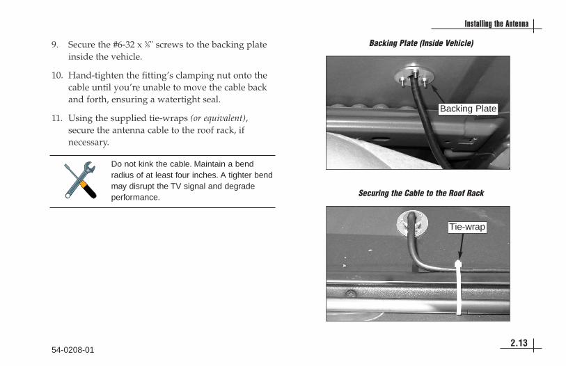
9. Secure the #6-32 x 5⁄8" screws to the backing plateinside the vehicle.
10. Hand-tighten the fitting’s clamping nut onto thecable until you’re unable to move the cable backand forth, ensuring a watertight seal.
11. Using the supplied tie-wraps (or equivalent),secure the antenna cable to the roof rack, ifnecessary.
54-0208-012.13
Installing the Antenna
Securing the Cable to the Roof Rack
Tie-wrap
Do not kink the cable. Maintain a bendradius of at least four inches. A tighter bendmay disrupt the TV signal and degradeperformance.
Backing Plate (Inside Vehicle)
Backing Plate

Option 2 - Routing the Cable Behind the Hatch1. Move the steel fitting down the length of the
antenna cable to the end opposite the rubberboot. You’ll need to connect the end of the cablewith the rubber boot to the antenna. You will notneed to use the fitting; simply keep it attached to theend of the cable inside the vehicle.
2. Starting from inside the vehicle, pass the antennacable through the gap in the hatch hinge.
3. Using a 7⁄16" wrench, connect the cable to theantenna’s connector.
54-0208-012.14
TracVision A5 Installation Guide
Cable Routed Behind Rear Hatch
Antenna CableHatch
Connecting the Antenna Cable to the Antenna
Antenna Connector
Rubber Boot
Connector
Rubber Boot
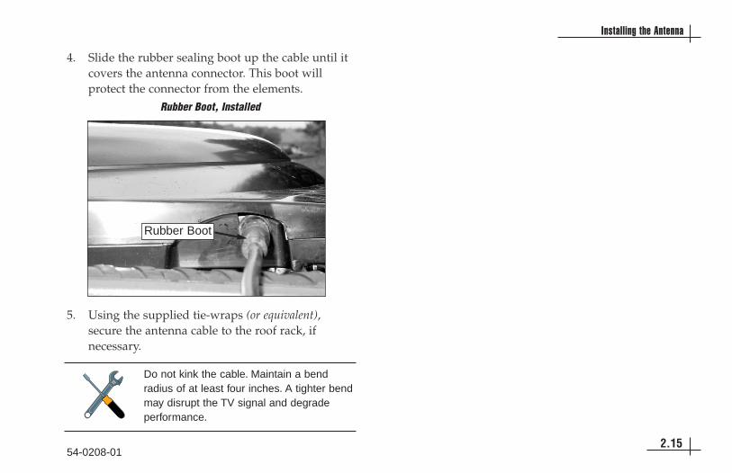
4. Slide the rubber sealing boot up the cable until itcovers the antenna connector. This boot willprotect the connector from the elements.
5. Using the supplied tie-wraps (or equivalent),secure the antenna cable to the roof rack, ifnecessary.
54-0208-012.15
Installing the Antenna
Rubber Boot, Installed
Rubber Boot
Do not kink the cable. Maintain a bendradius of at least four inches. A tighter bendmay disrupt the TV signal and degradeperformance.

54-0208-013.1
Installing the Receiver
3 Installing the ReceiverThis section explains how to connect all system cables to thereceiver and how to mount the receiver inside the vehicle.
Contents3-1 Wiring the Receiver . . . . . . . . . . . . . . . . . . . . . . . . . . .3.3
3-2 Mounting the Receiver . . . . . . . . . . . . . . . . . . . . . . . .3.12

54-0208-013.3
Installing the Receiver
3-1 Wiring the Receiver
Now that you’ve installed the antenna, you need toconnect the following cables to the receiver inside thevehicle:
• Antenna cable
• RF-to-IR converter cable orVehicle IR adapter cable (not supplied)
• Audio/video (A/V) cables
• DC power cable
The diagram on the following page shows thereceiver’s rear panel connections. Refer to this figurewhen connecting cables to the receiver.
The procedures in this section are intendedfor a basic wiring configuration. If thevehicle’s entertainment system is wireddifferently, use these procedures as a guideand connect the cables as needed to suitthe vehicle’s particular configuration.
DO NOT disconnect the two short cablesthat connect from one jack to another onthe receiver’s rear panel. The system willnot work if either of these cables areremoved.
To order a vehicle IR adapter cable, pleasecall KVH at (401) 847-3327.
54-0208-013.4
TracVision A5 Installation Guide
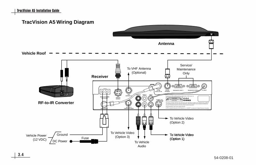
TracVision A5 Wiring Diagram
Antenna
For detailed system wiring instructions, referto the TracVision A5 Installation Guide.
RF-to-IR Converter
Receiver
Vehicle Roof
CAUTION
KVH® is a registered trademark of KVH Industries, Inc. HUGHES™ is a trademark of Hughes Electronics Corporation.
This device complies with Part 15J of the FCC rules. Operation is subject to the following two conditions: (1) This device must not cause harmful interference, and (2) This device must accept any interference received, including interference that may cause undesired operation.
Product Warranty void if outer casing removed.
VEHICLE POWER(10-16 VDC)
VHFANTENNA IN
S-VIDEO
TO KVHANTENNA
TO VIDEO
TruSurround, SRS and symbol are trademarks of SRS Labs, Inc.
SATELLITE IN
AUDIO R AUDIO L VIDEO
Service/Maintenance
Only
DC Power
Ground
To VehicleAudio
To Vehicle Video(Option 1)To Vehicle Video(Option 1)
To Vehicle Video(Option 3)
To Vehicle Video(Option 2)
To VHF Antenna(Optional)
Vehicle Power(12 VDC) Fuse
REMOTEIR INPUT
OUT TO TVCOMPOSITE VIDEO
TO IRD SATELLITE IN
DIAGNOSTIC PORT 1 DIAGNOSTIC PORT 2

54-0208-013.5
Installing the Receiver
Preparing the Antenna CableAt this point, the antenna cable should already beconnected to the antenna and routed to the receiver. Ifyou DO NOT need to cut the end of the antennacable, and you wish to simply coil the excess cableinside the vehicle, skip to “Connecting the AntennaCable” on page 3.7.
If you DO need to cut the antenna cable to thedesired length, follow the steps below.
1. Cut the antenna cable to the desired length. Besure the cable will reach the receiver rear panelwhile allowing plenty of slack.
2. Slide the F-connector assembly’s compressionfitting onto the raw cable before beginningconnector termination.
3. Twist and break off the connector body.
4. Push down the wire-stripping blade on theAugat tool so that youcan insert the antennacable.
End of Cable
Connector Body
Compression Fitting
TwistTo ensure a proper connection, you MUSTuse an LRC/Augat IT1000 crimp/strip toolto attach the supplied Snap-N-Seal®
F-connector to the end of the cable. Do notuse a screw-on, push-on, twist-on, or anyother over-the-counter connector. Such low-quality connectors WILL degrade systemperformance and KVH does not warranttheir use. If you do not have an LRC/Augat IT1000 tool, please order one from KVH at(401) 847-3327.

54-0208-013.6
TracVision A5 Installation Guide
5. Insert the antenna cable into thetool. Be sure to insert the cable inthe correct side, as noted on thetool. Let the blade clamp downon the cable.
6. The cable shouldextend just slightlybeyond the tool body.Twist the tool aroundthe cable for 3 or 4complete turns.
7. Hold the cable while pulling the tool so that itstrips off the cable jacket. The end of the cableshould now look like the figure below.
8. Fold the braid over the cable jacket, then slide theconnector body onto the prepared cable and slidethe compression fitting up into the connectorbody. Put the Snap-N-Seal ring up the cable, wideend first, then push the connector onto the cableuntil the foam is even with the bottom of theinside of the connector’s threaded end. The bodyof the connector should easily push up under thefoil and braid of the cable.
9. Move the handle awayfrom the tool and put thecable with the connectorin the tool cavity. Be surethe cable’s centerconductor is straight.
0.25"
0.25"
Sight Hole

10. Pull the lever toward thetool until you feel it“snap” as the ring isforced into the connector,making a weather-tightseal. A white indicatorwill appear in the sighthole (shown in the previousfigure) when the seal isachieved.
11. The F-connector is nowinstalled on the cable andready for use!
54-0208-013.7
Installing the Receiver
Connecting the Antenna CableConnect the antenna cable to the “To KVH Antenna”jack on the receiver’s rear panel. Screw the connectordown securely, but don’t use excessive force; finger-tight is sufficient.

54-0208-013.8
TracVision A5 Installation Guide
Connecting the RF-to-IR Converter CableThe RF-to-IR converter’s “Y” cable supplies 8 VDCpower to the converter and relays remote controlsignals to the receiver. To connect the cable, followthe steps below.
1. Connect the forkedend of the cable tothe RF-to-IRconverter’s rearpanel jacks.
2. Connect the other end of the cable to the “RemoteIR Input” jack on the receiver’s rear panel.
3. Place the RF-to-IR converter at least three feetaway from the receiver’s location.
Connecting an Existing IR Input (Optional)
If you prefer, instead of the RF-to-IR converter, youcan connect an existing IR input (such as a TVscreen’s IR eye) to the receiver.
1. Connect the desiredIR input to theadapter cable (notsupplied – order fromKVH).
2. Connect the otherend of the adaptercable to the“Remote IR Input”jack on thereceiver’s rearpanel.
RF-to-IR Converter Rear Panel
Receiver
VEHICLE POWER(10-16 VDC) REMOTE
IR INPUT
To Vehicle'sIR System
Vehicle IR Adapter Cable(Not Supplied)
If you choose this option, you will need toaim the remote control at the IR eyewhenever you use the remote control. Thereceiver will not be able to receive RFsignals from the remote control.
The RF-to-IR converter MUST be placed atleast three feet away from the receiver.Placing the RF-to-IR converter closer to thereceiver may result in IR interference,causing the remote control to operateintermittently or not at all.

54-0208-013.9
Installing the Receiver
Connecting the Audio/Video CablesThe TracVision A5 kitpack includes standardaudio/video (A/V) cables with RCA-type connectorsfor connecting the receiver to the vehicle’sentertainment system. However, the receiver’s rearpanel also offers an S-video jack and a compositevideo jack, if needed. Follow the procedure below foryour particular installation. If you need to connect aVCR or DVD player to the vehicle’s entertainmentsystem, see the alternate wiring instructions in thenext section, “Connecting a VCR or DVD Player.”
Option 1 - RCA-type A/V Jacks (very good picture quality)
Option 2 - S-Video Jack (best picture quality)
Option 3 - RF Coaxial Connector (good picture quality)
Option 1 - RCA-type A/V Jacks (very good picture quality)
If the vehicle’s entertainment system has standardRCA-type A/V jacks, follow the steps below.
1. Connect the supplied audio/video cables to thelower “Audio R,” “Audio L,” and “Video” jackson the receiver’s rear panel.
2. Connect the other ends of the audio/video cablesto the entertainment system’s audio and videoinputs. If the system has only one audio input jack,connect the audio cable that is connected to thereceiver’s “Audio L” jack.
Option 2 - S-Video Jack (best picture quality)
If the vehicle’s entertainment system has a high-quality S-Video jack, follow the steps below.
1. Connect an S-Video cable (not supplied) to the “S-Video” jack on the receiver’s rear panel.
2. Connect the other end of the S-Video cable to theentertainment system’s S-Video input.

54-0208-013.10
TracVision A5 Installation Guide
3. Connect two of the supplied audio/video cables(with the red and white connectors) to the“Audio R” and “Audio L” jacks on the receiver’srear panel.
4. Connect the other ends of the audio cables to theentertainment system’s audio inputs. If the systemhas only one audio input jack, connect the audio cablethat is connected to the receiver’s “Audio L” jack.
Option 3 - RF Coaxial Connector (good picture quality)
If the entertainment system has just an RF (coaxial)connector and is equipped with a built-in TV tuner,follow the steps below.
1. Connect an RF cable (not supplied) to the “Out toTV” jack on the receiver’s rear panel.
2. Connect the other end of the RF cable to theentertainment system’s VHF/UHF or RF input.
Connecting a VCR or DVD Player (Optional)To connect a VCR or DVD player to the vehicle’sTracVision-equipped entertainment system, followthe steps below.
1. Connect the VCR/DVD player to the TracVision A5 receiver:
If the VCR has RCA-type A/V connectors:a. Connect the supplied audio/video cables to
the lower “Audio R,” “Audio L,” and “Video” jacks on the receiver’s rear panel.
b. Connect the other ends of the audio/video cables to the VCR’s audio and video inputs. Ifthe VCR has only one audio input jack, connect the audio cable that is connected to the receiver’s “Audio L” jack.
If the VCR only has an RF (coaxial) connector:a. Connect an RF cable (not supplied) to the
“Out to TV” jack on the receiver’s rear panel.
b. Connect the other end of the RF cable to the VCR’s VHF/UHF or RF input.

2. Connect the VCR/DVD player to the vehicle’sentertainment system:
If the entertainment system and VCR have RCA-type A/V connectors:Connect a set of audio/video cables from theVCR’s audio and video output jacks to theentertainment system’s audio and video inputs.
If the entertainment system or VCR only has anRF (coaxial) connector:Connect an RF cable from the VCR’s VHF/UHFor RF output jack to the entertainment system’sVHF/UHF or RF input.
Connecting a VHF Antenna (Optional)If you need to connect an existing VHF antenna to thevehicle’s TracVision-equipped entertainment system,simply connect the cable to the receiver’s “VHFAntenna In” jack.
Connecting the Power CableNow that you’ve connected all other cables to thereceiver, follow the steps below to connect the powercable.
1. Ensure that vehicle power is turned off.
2. Disconnect vehicle power by either removing thepositive lead from the vehicle’s battery orremoving the appropriate vehicle fuse.
3. Connect the receiver’s power cable to thevehicle’s switched (accessory) power via the fusebox. Connect the red wire to the +12 VDC supply;connect the black wire to ground. DO NOTconnect the system directly to the vehicle’sbattery – the TracVision system will drain thebattery.
54-0208-013.11
Installing the Receiver
Before connecting the receiver power cable,be sure that vehicle power is turned off andpower is disconnected from the circuit.
4. Plug the other end of the power cable into the“Vehicle Power” jack on the receiver’s rear panel.
5. Reconnect the battery lead or vehicle fuse thatyou removed in Step 2.
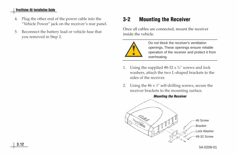
3-2 Mounting the Receiver
Once all cables are connected, mount the receiverinside the vehicle.
1. Using the supplied #8-32 x 5⁄16" screws and lockwashers, attach the two L-shaped brackets to thesides of the receiver.
2. Using the #6 x 1⁄2" self-drilling screws, secure thereceiver brackets to the mounting surface.
54-0208-013.12
TracVision A5 Installation Guide
Mounting the Receiver
Do not block the receiver’s ventilationopenings. These openings ensure reliableoperation of the receiver and protect it fromoverheating.
Bracket
Lock Washer
#6 Screw
#8-32 Screw

54-0208-014.1
Completing the Installation
4 Completing the InstallationThis section explains how to turn on and test the TracVision A5system. It also explains how to activate the receiver for DIRECTV®
programming and how to program the remote control.
Contents4-1 Installing the Remote Control Batteries . . . . . . . . . . . .4.3
4-2 Post-installation Checklist . . . . . . . . . . . . . . . . . . . . . .4.4
4-3 Testing the System . . . . . . . . . . . . . . . . . . . . . . . . . . .4.6
4-4 Activating the Receiver . . . . . . . . . . . . . . . . . . . . . . . .4.7
4-5 Programming the Remote Control to Operate Other Components (Optional) . . . . . . . . . . . . .4.8
54-0208-014.3
Completing the Installation
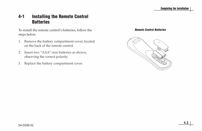
4-1 Installing the Remote ControlBatteries
To install the remote control’s batteries, follow thesteps below.
1. Remove the battery compartment cover, locatedon the back of the remote control.
2. Insert two “AAA”-size batteries as shown,observing the correct polarity.
3. Replace the battery compartment cover.
Remote Control Batteries
54-0208-014.4
TracVision A5 Installation Guide
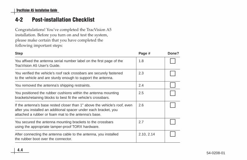
4-2 Post-installation Checklist
Congratulations! You’ve completed the TracVision A5installation. Before you turn on and test the system,please make certain that you have completed thefollowing important steps:
Step Page # Done?
You affixed the antenna serial number label on the first page of the 1.8TracVision A5 User’s Guide.
You verified the vehicle’s roof rack crossbars are securely fastened 2.3to the vehicle and are sturdy enough to support the antenna.
You removed the antenna’s shipping restraints. 2.4
You positioned the rubber cushions within the antenna mounting 2.5brackets/retaining blocks to best fit the vehicle’s crossbars.
If the antenna’s base rested closer than 1" above the vehicle’s roof, even 2.6after you installed an additional spacer under each bracket, you attached a rubber or foam mat to the antenna’s base.
You secured the antenna mounting brackets to the crossbars 2.7 using the appropriate tamper-proof TORX hardware.
After connecting the antenna cable to the antenna, you installed 2.10, 2.14the rubber boot over the connector.

54-0208-014.5
Completing the Installation
Step Page # Done?
If you routed the antenna cable through the roof, you used the 2.12supplied fitting and backing plate and sealed the holes.
You did not disconnect the two short cables pre-connected on the 3.3receiver’s rear panel.
If you cut the antenna cable, you used an LRC/Augat IT1000 tool 3.5to attach the supplied F-connector to the end of the cable.
You connected the antenna cable to the receiver. 3.7
You connected the RF-to-IR converter to the receiver and placed it 3.83 feet away from the receiver. (Or you connected an existing IR input tothe receiver via the optional adapter cable.)
You connected the audio/video cables from the receiver to the 3.9vehicle’s entertainment system.
You connected the receiver’s power cable to switched (accessory) 3.11power.
You mounted the receiver in a dry location away from any heat sources 3.12and allowing plenty of room for ventilation.
You installed two “AAA”-size batteries in the remote control. 4.3
Receiver Location:

4-3 Testing the System
Now all you need to do is turn the system on andensure everything works properly. Follow the stepsbelow to turn on the TracVision A5 system and verifyproper operation.
1. Ensure that the antenna has a clear view of thesatellite. The antenna requires an unobstructedview of the southern sky to receive satellite TVsignals. Trees, buildings, highway overpasses,etc., can block satellite signals. Heavy rain orsnow may also interrupt satellite signals. Forcomplete details about satellite receptionrequirements, refer to Section 1.3, “ReceivingSatellite TV Signals,” in the TracVision A5 User’sGuide.
2. Apply vehicle power and turn on the vehicle’sentertainment system.
3. Turn on the TracVision A5 receiver’s front panelpower switch. The switch’s light illuminates andthe receiver beeps twice.
4. Wait 30 seconds. The antenna should then poweroff and the receiver should beep once.
5. Press the remote control’sSAT button. The buttonshould blink red. If itdoesn’t, check the remotecontrol’s batteries.
6. Now press the POWERbutton. The receiverbeeps twice to indicatethat power is againapplied to the antenna.
54-0208-014.6
TracVision A5 Installation Guide
PAGE
CHVOL
PWR
DVD VCR AUX TV SAT
GUIDE
MENU
INFO CLEAR
TURBOFAV
SELECT
MUTE CHPREV
PAGE
ONELINE GUIDE
Since the TracVision antenna requires anunobstructed view of the southern sky toreceive satellite signals, the system will notwork when the vehicle is in a garage.
Receiver Front Panel Power Switch
Power Switch

7. Verify that the following appears on the TV(s):
The TracVision antenna searches for and locksonto the satellite. The receiver then startsdownloading the program guide and thefollowing message appears:
This process may take up to 60 seconds. Once theprogram guide has loaded, a DIRECTVprogramming channel appears. Only theDIRECTV preview channels (such as channels 100and 201) are viewable until the user activates thereceiver.
4-4 Activating the Receiver
Before the customer can start watching satellite TVvia the TracVision A5, the receiver must be activated.To activate the receiver, the customer needs to followthe steps below:
1. Call KVH’s Activation Department at:
1-866-551-8004(24 hours a day, 7 days a week)
2. After activation is complete, KVH’s ActivationDepartment will provide an access card numberand receiver ID number. Enter these numbers inthe associated boxes on page v of the TracVision A5 User’s Guide.
54-0208-014.7
Completing the Installation
Installation
If your satellite dish is ready for DIRECTV®
service, please wait until yourAdvanced Program Guide™ is prepared.
Searching for satellite signal...
Installation
If your satellite dish is ready for DIRECTV®
service, please wait until yourAdvanced Program Guide™ is prepared.
Acquiring guide data...
The customer must have his/her credit cardand system serial numbers handy whencalling to activate. The serial numbers arenoted on the first page of the TracVision A5User’s Guide. The receiver cannot beactivated without these numbers.
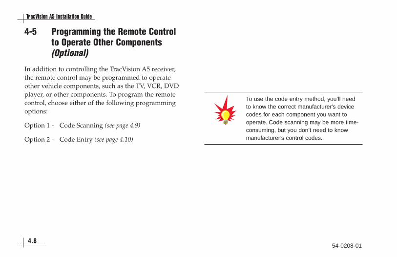
4-5 Programming the Remote Controlto Operate Other Components(Optional)
In addition to controlling the TracVision A5 receiver,the remote control may be programmed to operateother vehicle components, such as the TV, VCR, DVDplayer, or other components. To program the remotecontrol, choose either of the following programmingoptions:
Option 1 - Code Scanning (see page 4.9)
Option 2 - Code Entry (see page 4.10)
54-0208-014.8
TracVision A5 Installation Guide
To use the code entry method, you’ll needto know the correct manufacturer’s devicecodes for each component you want tooperate. Code scanning may be more time-consuming, but you don’t need to knowmanufacturer’s control codes.

Option 1 - Code Scanning1. Keep the remote control aimed at the IR input (or
“eye”) for the component you want to control.For example, if you want to program the remotecontrol to operate the TV, keep the remote aimedat the TV’s IR input (many in-vehicle TVs comewith an IR eye built into the screen).
2. Press and hold the remote control’s componentbutton (for example, TV).
3. At the same time, press the MUTE button for twoseconds.
4. Release both buttons.
The component button should light and remainlit. If it doesn’t remain lit, repeat Steps 1 through4 above.
5. Repeatedly press the upper part of theCHANNEL (CH) button.
6. Continue pressing the CHANNEL (CH) button tostep through the codes until the component turnsoff, indicating that you have found the correctdevice code. If you accidentally pass a code thatresponds or realize you may not have been aiming theremote control at the component, repeatedly press thelower part of the CHANNEL (CH) button to stepbackward through the codes.
7. Press the remote control’s POWER button toverify that you have found the proper code. Thecorrect code will turn the component on and off.
8. Press the component button again to lock in thecode (in this example, the TV button).
54-0208-014.9
Completing the Installation
CH PAGE
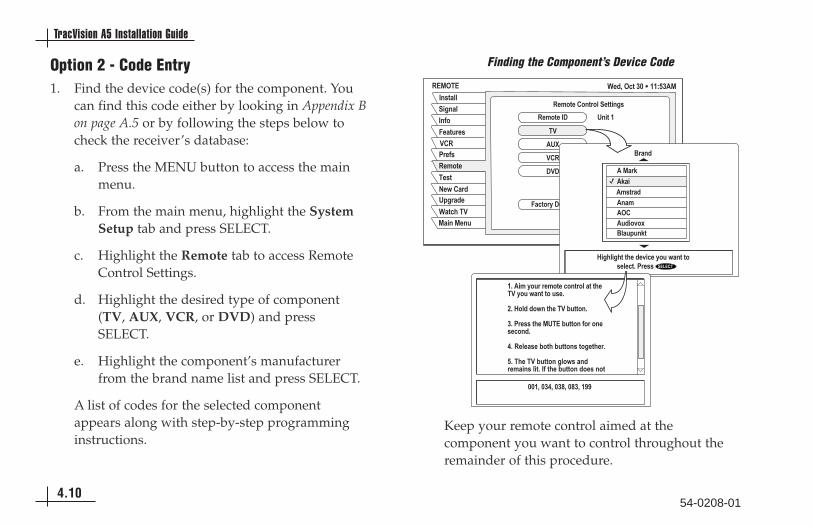
Option 2 - Code Entry1. Find the device code(s) for the component. You
can find this code either by looking in Appendix Bon page A.5 or by following the steps below tocheck the receiver’s database:
a. Press the MENU button to access the main menu.
b. From the main menu, highlight the System Setup tab and press SELECT.
c. Highlight the Remote tab to access Remote Control Settings.
d. Highlight the desired type of component (TV, AUX, VCR, or DVD) and press SELECT.
e. Highlight the component’s manufacturer from the brand name list and press SELECT.
A list of codes for the selected componentappears along with step-by-step programminginstructions.
Keep your remote control aimed at thecomponent you want to control throughout theremainder of this procedure.
54-0208-014.10
TracVision A5 Installation Guide
������
������ ���
���������������������
������
�����
�!�"�����
���#
$%������&��'
'"�
� ������
��(#��"#��#���� ���
��(#�
�'
�$)
'"�
*'*
��#�+�*�����
��(#���* $� ��
,���
����-
�(�����(��"��� #.#/
�-
,��%��-
0 �&� �&�&����. ���+#��!��#�����������������1������ ��2�"�
�������3����4���4����55
�1�� (�+#�����(#���#��#���&��'�+#��!��#����1
61�0#����#!��&���'�7�#�1
�1�������&���$���7�#���#��#�����#��1
31��������7#&�7�#���#��&��1
�1��&���'�7�#����#!������( ���� 1����&��7�#���#����#
Finding the Component’s Device Code

2. Press and hold the remote control’s componentbutton (for example, TV).
3. At the same time, press the MUTE button for twoseconds.
4. Release both buttons.
The component button should light and remainlit. If it doesn’t remain lit, follow Steps 2 through4 above.
5. Using the remote control’s numeric keypad, entera device code.
6. After entering a code, press the remote control’sPOWER button to test it. The correct code willturn the component on and off. If several codesare listed for the component’s type and brand, tryeach of them until you find the code that turnsthe component on/off. If none of these codeswork, try the code scanning method described onpage 4.9.
7. Press the component button again to lock in thecode (in this example, the TV button).
54-0208-014.11
Completing the Installation

54-0208-01A.1
Appendices
AppendicesThis section provides a list of system specifications and a list ofdevice codes for programming the remote control.
ContentsA System Specifications . . . . . . . . . . . . . . . . . . . . . . . . .A.3
B Manufacturer Device Codes . . . . . . . . . . . . . . . . . . . . .A.5
Warranty . . . . . . . . . . . . . . . . . . . . . . . . . . . . . . . . . . . . . . . .A.17

54-0208-01A.3
System Specifications
Appendix ASystem SpecificationsPhysical Characteristics
Power 9-16 volts DC, 50 watts
Antenna Dimensions 30.5" wide x 5.3" high
Antenna Weight 48 lbs
Receiver Dimensions 11.7" wide x 11.4" long x 3" high
Receiver Weight 4.3 lbs
Pointing System
Elevation Range 31º to 57º
Azimuth Range Unlimited
Turn/Track Rate 45º per second
Wind (EME) Force 100 mph
Stabilization 2-axis, actively gyro-stabilized
Environmental
Operating Temperature -13ºF to +131ºF (-25ºC to +55ºC)
Storage Temperature -20ºF to +140ºF (-29ºC to +60ºC)
Humidity to 100 percent
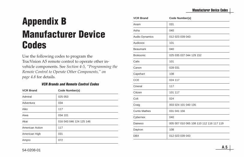
Appendix BManufacturer DeviceCodesUse the following codes to program the TracVision A5 remote control to operate other in-vehicle components. See Section 4-5, “Programming theRemote Control to Operate Other Components,” on page 4.8 for details.
VCR Brand Code Number(s)
Admiral 025 053
Adventura 034
Aiko 117
Aiwa 034 101
Akai 016 043 046 124 125 146
American Action 117
American High 031
Ampro 072
VCR Brand Code Number(s)
Anam 031
Asha 040
Audio Dynamics 012 023 039 043
Audiovox 101
Beaumark 040
Broksonic 025 035 037 044 129 152
Calix 101
Canon 028 031
Capehart 108
CCE 024 117
Cineral 117
Citizen 101 117
Colt 024
Craig 003 024 101 040 135
Curtis Mathes 031 041 156
Cybernex 040
Daewoo 005 007 010 065 108 110 112 116 117 119
Daytron 108
DBX 012 023 039 043
54-0208-01A.5
Manufacturer Device Codes
VCR Brands and Remote Control Codes

VCR Brand Code Number(s)
Dimensia 156
Dynatech 034 053
Electrohome 059 101
Electrophonic 101
Emerson 006 017 025 027 029 031 034 035 036 037 044046 101 117 129 131 138 152 153 157
Fisher 003 008 009 010
Fuji 031
Funai 034
Garrard 034
GE 031 040 053 063 072 107 109 126 144 147 151156
GO Video 040 132 136
Goldstar/LG 001 101 012 114 123
Harley Davidson 034
Harman Kardon 012 045
Harwood 024
Hitachi 001 026 034 063 137 150 156
Hughes 001
HQ 034
VCR Brand Code Number(s)
Instantreplay 031
JCL 031
JCPenney 001 012 031 040 066 101 156
Jensen 043
JVC 048 050 043 130 060 012 031 150 055 158
KEC 101 117
Kenwood 014 023 034 047 048
KLH 024
Kodak 031 101
Lloyd 034
Logik 024
LXI 034 003 009 017 101
Magin 040
Magnasonic 117
Magnavox 067 031 034 041 064 068 154 160
Marantz 012 023 031 067 069
Marta 101
Matsui 027 030
Matsushita 031
54-0208-01A.6
TracVision A5 Installation Guide

VCR Brand Code Number(s)
MEI 031
Memorex 003 010 014 025 031 034 040 053 072 101 102134 139
MGA 045 046 059
MGN Technology 040
Minolta 001 156
Mitsubishi 001 045 046 053 059 061 162
Motorola 031 053
MTC 034 040
Multitech 024 034
NEC 012 023 039 043 048
Nikko 101
Noblex 040
Nordmende 043
Olympus 031
Optimus 053 101
Optonica 053 054
Orion 025
Panasonic 031 066 070 133 160 161
VCR Brand Code Number(s)
Pentax 001 031 063 156
Philco 025 031 034 067
Philips 031 034 054 067 071 101
Pilot 101
Pioneer 001 021 048
Portland 108
Profitronic 040
Protec 024
Quartz 002 014
Quasar 031 066 070 133 160 161
Radio Shack 034 123
Radix 101
Randex 101
RCA 001 031 034 040 041 053 107 109 140 144 147151 156
Realistic 003 008 010 014 031 034 040 053 054 101
Rico 058 078
Salora 014
Samsung 032 040 102 104 107 109 112 113 115 120 122125 159
54-0208-01A.7
Manufacturer Device Codes

VCR Brand Code Number(s)
Sanky 053
Sansui 022 025 034 043 048 135
Sanyo 003 010 007 014 040 102 134
Scott 017 037 044 112 129 131 159
Sears 001 003 008 009 010 014 017 031 034 081 101
Sharp 031 054 053 143
Shintom 024
Shogun 040
Signature 034
Singer 024
Sony 003 031 032 034 052 056 057 058 155
Soundesign 034
STS 001
Sylvania 031 034 059 067
Symphonic 034
Tandy 010 034
Tatung 023 039 043
Teac 023 034 039 043
Technics 031 070
VCR Brand Code Number(s)
Teknica 031 019 034 101
Thomas 034
TMK 040
Toshiba 001 008 042 047 059 082 112 131
Totevision 040 101
Unitech 040
Vector Research 012
Video Concepts 012 034 046
Videosonic 040
Wards 001 003 017 024 031 034 040 053 054 131
Westinghouse 024 025
XR-1000 024 031 034
Yamaha 012 034 039 043
Zenith 025 034 048 056 058 072 080 101
54-0208-01A.8
TracVision A5 Installation Guide
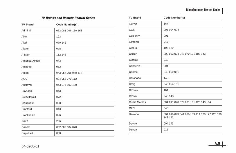
TV Brand Code Number(s)
Admiral 072 081 096 160 161
Aiko 103
Akai 070 146
Alaron 028
A Mark 112 143
America Action 043
Amstrad 052
Anam 043 054 056 080 112
AOC 004 058 070 112
Audiovox 043 076 103 120
Baysonic 043
Bell&Howell 072
Blaupunkt 088
Bradford 043
Brooksonic 096
Cairn 206
Candle 002 003 004 070
Capehart 058
TV Brand Code Number(s)
Carver 164
CCE 001 004 024
Celebrity 001
Cetronic 043
Cineral 103 120
Citizen 002 003 004 043 070 101 103 143
Classic 043
Concerto 004
Contec 043 050 051
Coronado 143
Craig 043 054 191
Crosley 164
Crown 043 143
Curtis Mathes 004 011 070 072 081 101 120 143 164
CXC 043
Daewoo 004 016 043 044 076 103 114 120 127 128 136143 192
Daytron 004 143
Denon 011
54-0208-01A.9
Manufacturer Device Codes
TV Brands and Remote Control Codes

TV Brand Code Number(s)
Dumont 004 073
Dynasty 043
Dynatech 062
Electroband 001
Electrohome 024 076 120 143
Emerson 004 005 028 043 047 048 050 051 070 076 096120 143 151 153 154 155 191
Fisher 007 057
Fujitsu 028 198 210 211
Funal 028 043 052
Futuretech 043
GE 004 008 009 034 056 070 073 074 081 120 130145 155 160 165 161 167
Gibralter 004 073
Goldstar/LG 004 106 110 112 119 127 143 193
Gradiente 004 038 106
Grunpy 028 043
Hall Mark 004
Harley Davidson 028
Harvard 043
TV Brand Code Number(s)
Hitachi 004 007 009 010 011 012 023 072 075 143 158
Harman Kardon 164
Infinity 164
Inteq 073
JBL 164
JCB 001
JCPenney 004 008 009 024 030 065 070 101 143 156 160
Jensen 013
JVC 001 034 038 083 199 208
KEC 043
Kenwood 001 070
Kloss 002 059
KMC 143
KTV 043 070 143 154
Lodgenet 072
Loewe 209 211
Logik 072
Luxman 004
LXI 007 015 052 081 160 164
54-0208-01A.10
TracVision A5 Installation Guide
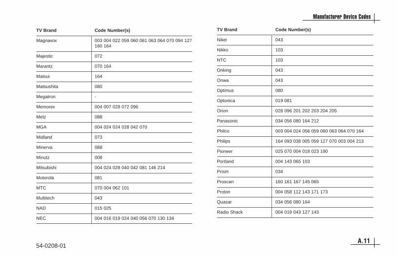
TV Brand Code Number(s)
Magnavox 003 004 022 059 060 061 063 064 070 094 127160 164
Majestic 072
Marantz 070 164
Matsui 164
Matsushita 080
Megatron -
Memorex 004 007 028 072 096
Metz 088
MGA 004 024 024 028 042 070
Midland 073
Minerva 088
Minutz 008
Mitsubishi 004 024 028 040 042 081 146 214
Motorola 081
MTC 070 004 062 101
Multitech 043
NAD 015 025
NEC 004 016 019 024 040 056 070 130 134
TV Brand Code Number(s)
Nikei 043
Nikko 103
NTC 103
Onking 043
Onwa 043
Optimus 080
Optonica 019 081
Orion 028 096 201 202 203 204 205
Panasonic 034 056 080 164 212
Philco 003 004 024 056 059 060 063 064 070 164
Philips 164 093 038 005 059 127 070 003 004 213
Pioneer 025 070 004 018 023 190
Portland 004 143 065 103
Prism 034
Proscan 160 161 167 145 065
Proton 004 058 112 143 171 173
Quasar 034 056 080 164
Radio Shack 004 019 043 127 143
54-0208-01A.11
Manufacturer Device Codes

TV Brand Code Number(s)
RCA 160 161 156 165 065 070 004 023 024 056 074081 152 167 145
Realistic 007 019 043 047
Runco 073 130
Sampo 004 070 058 207
Samsung 101 004 050 089 105 160 127 143 133 215
Sansei 120
Sansui 096
Sanyo 007 020 053 057 082
Scotch 004
Scott 004 028 043 048 143
Sears 004 007 015 028 030 052 057 082 094 143 160164 167
Seleco 200
Semivox 043
Semp 015
Sharp 004 014 019 022 028 081 143
Siemens 088
Signature 072
Sony 001 079 126
TV Brand Code Number(s)
Soundesign 003 004 028 043
Spectricon 112
Squareview 052
SSS 004 043
Starlight 043
Supre Macy 002
Supreme 001
Sylvania 003 044 059 060 063 064 070 127 160 164
Symphonics 194 052
Tandy 081
Tatung 056 062
Technics 034 080
Technol Ace 028
Techwood 004
Teknika 002 003 004 024 028 043 072 101 103 143 164
Telerent 072
Tera 173
TMK 004
TNCI 073
54-0208-01A.12
TracVision A5 Installation Guide

TV Brand Code Number(s)
Toshiba 015 030 007 040 062 101
Universal 008 009
Video Concepts 146
Vidikron 164
Vidtech 004
Wards 004 008 009 019 028 060 061 063 064 072 074143 164 165
Westinghouse 120 076
Yamaha 004 070
York 004
Yupiteru 043
Zenith 011 072 073 095 096 103
Zonda 112
AUX Brand Code Number(s)
Adcom 146 149 227 244
AMC 083 084
Arcam 100
Audio File 093 098
Audio Techinica 221
Aiwa 111 114 117 156 170 199 203 219 231 241 254
Akal 181 233
Anam 180
Bose 064 137 219
B & K 150 152
Carver 013 098 107 126 129 160 163 220 245 249
Clarion 151 169
Denon 101 133 191 202 208 246 247
Englightened Audio 078 153
Fisher 107 129 157 163 176
Fosgate Audionics 228 248
GE 123 216
Harmon Kardon 073 195 248 249
54-0208-01A.13
Manufacturer Device Codes
AUX Brands and Remote Control Codes

AUX Brand Code Number(s)
Haitai 119
Hitachi 088
JCPenney 109 154 178
Jensen 099
Jerrold 141
JVC 112 198 252
Kenwood 096 104 119 125 148 151 163 171 173 242
Krell 223
Lexicon 215 250
Luxman 066 120 205 229
LXI 123 177
Magnavox 126 162 185 186 224 228
Marantz 074 105 126 128 139 155 162 186 232
McIntosh 251
Mondial 069 225
MCS 178
Mitsubishi 253
Meridian 013 067
NAD 128
AUX Brand Code Number(s)
Nakamichi 072 212 234 235
Niles 236
Onkyo 094 115 116 209 211 255
Optimus 121 125 140 181
Panasonic 131 144 187 200
Parasound 085 086 090
Philips 126 136 186 197
Pioneer 081 093 138 165 189 195 230 243
Quasar 131 187
RCA 109 166 213
Realistic 103 122 123 124 172 174 177 179 180 194
Rotel 204 218 239
Sansui 075 126 139 196 197 214
Sanyo 129 157
Samsung 068
Scott 180 190
Sharp 096 125 151 161 169 182 193
Sherwood 089 127
Sony 097 117 147 183 188 192 200 237 238 253
54-0208-01A.14
TracVision A5 Installation Guide

AUX Brand Code Number(s)
Soundstream 197
Starcom 141
Symphonic 124
Teac 062 102 159 180
Technics 131 165 184 187 200 202 208
Toshiba 175
Wards 163
Yamaha 092 120 125 166 169 216 240
Zenith 061 222
DVD Brand Code Number(s)
Alpine 009
Apex Digital 075 076
Arcam 065
Cyberhome 087
Daewoo 087
Denon 030 226
GE 035 036
Goldstar/LG 028 041
Harmon Kardon 217
Hitachi 011
Hiteker 076
JVC 031
Kenwood 070
Magnavox 008 038 042
Marantz 006 007
McIntosh 071
Mitsubishi 032
NAD 077
54-0208-01A.15
Manufacturer Device Codes
DVD Brands and Remote Control Codes

DVD Brand Code Number(s)
Onkyo 207
Optimus 034
Panasonic 003 039
Philips 006 007 038 042 063
Pioneer 005 010 034
Proceed 002
Proscan 035 036
RCA 035 036
Samsung 029 040 095
Sharp 004
Sony 037 080
Technics 003
Theta Digital 034
Toshiba 001 038 082 091 206
Yamaha 039 079
Zenith 028 041
DVD-Laser Disc Brand Code Number(s)
California Audio 047
Denon 043 044
Fisher 047
Kenwood 060
Magnavox 048 057
Mitsubishi 057
NAD 057
Panasonic 047 051 054
Philips 048
Pioneer 055 057
Quasar 047
RCA 046
Sanyo 052
Sharp 060
Sony 050 053
Technics 047 051 054
Toshiba 060
Yamaha 045 059
54-0208-01A.16
TracVision A5 Installation Guide
DVD-Laser Disc Brands and Remote Control Codes

54-0208-01A.17
Warranty
KVH Industries Limited Warranty - TracVision A5Limited Warranty on Hardware
KVH Industries, Inc. warrants the KVH product purchased againstdefects in materials for a period of ONE (1) year and against factory laborcosts for a period of ONE (1) year from the date of original retail purchase bythe original purchaser. It is the customer’s responsibility to verify the date ofpurchase by providing a copy of a dated sales receipt for the KVH productunder warranty with the warranty claim. If this date cannot be verified, thewarranty period will begin 30 days after the date of manufacture of theoriginal product purchased.
If you discover a defect, KVH will, at its option, repair, replace or refundthe purchase price of the product at no charge to you, provided you return itduring the warranty period, transportation charges prepaid, to the factorydirect. Please attach your name, address, telephone number, a description ofthe problem and a copy of the bill of sale or sales receipt as proof of date oforiginal retail purchase, to each product returned to warranty service.
This Limited Warranty does not apply if the product has been damagedby accident, abuse, misuse or misapplication or has been modified withoutthe written permission of KVH; if any KVH serial number has been removedor defaced; or if any factory-sealed part of the system has been openedwithout authorization.
Return AuthorizationA Return Material Authorization is required prior to returning the
product to KVH Industries. Please call our Technical Support Department at+1 401 847-3327 or send an e-mail to [email protected] to obtain the RMAnumber. Write the number in large, clear characters on the outside of thebox. To avoid confusion and misunderstandings, shipments without an RMAnumber clearly visible on the outside box will be refused and returned to youat your expense. If possible, use the original box and packing material toprotect the equipment from damage in shipment. KVH assumes noresponsibility for warranty shipments from the customer to the factory if notshipped in the manner prescribed above.
THE EXPRESS WARRANTIES SET FORTH ABOVE ARE THE ONLYWARRANTIES GIVEN BY KVH WITH RESPECT TO ANY PRODUCTFURNISHED HEREUNDER; KVH MAKES NO OTHER WARRANTIES,EXPRESS, IMPLIED OR ARISING BY CUSTOM OR TRADE USAGE, ANDSPECIFICALLY DISCLAIMS ANY WARRANTY OF MERCHANTABILITY OROF FITNESS FOR A PARTICULAR PURPOSE. SAID EXPRESSWARRANTIES SHALL NOT BE ENLARGED OR OTHERWISE AFFECTEDBY TECHNICAL OR OTHER ADVICE OR SERVICE PROVIDED BY KVH INCONNECTION WITH ANY PRODUCT.
KVH's liability in contract, tort or otherwise arising out of or inconnection with any product shall not exceed the price paid for the product.IN NO EVENT SHALL KVH BE LIABLE FOR SPECIAL, PUNITIVE,INCIDENTAL, TORT OR CONSEQUENTIAL DAMAGES OR LOST PROFITSOR GOODWILL (INCLUDING ANY DAMAGES RESULTING FROM LOSSOF USE, DELAY IN DELIVERY OR OTHERWISE) ARISING OUT OF OR INCONNECTION WITH THE PERFORMANCE OR USE OR POSSESSION OFANY PRODUCT, OR ANY OTHER OBLIGATIONS RELATING TO THEPRODUCT, EVEN IF KVH HAS BEEN ADVISED OF THE POSSIBILITY OFSUCH DAMAGES.
If any implied warranty, including implied warranties of merchantabilityand fitness for a particular purpose, cannot be excluded under applicablelaw, then such implied warranty shall be limited in duration to ONE (1) YEARfrom the date of the original retail purchase of this product by the originalpurchaser.
Some states/countries do not allow the exclusion or limitation of impliedwarranties or liability for incidental or consequential damages, so the abovelimitations may not apply to you. This warranty gives you specific legal rights,and you may also have other rights which vary from state/country tostate/country.

TV_A
5_IM
_Cov
er_8
.03
KVH Industries, Inc. 50 Enterprise Center • Middletown, RI 02842 U.S.A .• Phone: (401) 847-3327 • Fax: (401) 849-0045 • E-mail: [email protected]
www.kvh.com
© Copyright 2003, KVH Industries, Inc. KVH® and TracVision® are trademarks of KVH Industries, Inc.