traction power system study for metro-north railroad
TRANSCRIPT
_______________________________________________________________________________________________International Conference On Computer Modeling For Rail Operations February 2004, Florida USAJ G Yu – Traction Power System Study For Metro-North Railroad Page 1
COMPUTER MODELING FOR COMPLEX ENGINEERING DECISIONS
Traction Power System Study For Metro-North RailroadJ G YuSYSTRA Consulting, Inc.
1 INTRODUCTION.................................................................................................................... 22 DC SYSTEM STUDY ............................................................................................................. 2
2.1 Load flow model .............................................................................................................................22.2 Organization of Simulation Results.................................................................................................3
3 FIELD DATA GATHERING .................................................................................................. 43.1 Measurement for substation data.....................................................................................................53.2 Measurement for train data..............................................................................................................73.3 The Benefit of Field Test.................................................................................................................83.4 Model Validation.............................................................................................................................9
4 A TOOL FOR DECISION MAKING.................................................................................... 104.1 Upgrading And Renewal of The Electrical Network.....................................................................104.2 Substation Capacity Assessment ...................................................................................................104.3 Power Delivery Ability..................................................................................................................124.4 Energy Consumption Estimation...................................................................................................144.5 System Compatibility ....................................................................................................................144.6 Application of New Technology ...................................................................................................16
5 AC SYSTEM STUDY ........................................................................................................... 186 CONCLUSIONS .................................................................................................................... 187 ACKNOWLEDGEMENT...................................................................................................... 18APPENDIX.................................................................................................................................... 19

_______________________________________________________________________________________________International Conference On Computer Modeling For Rail Operations February 2004, Florida USAJ G Yu – Traction Power System Study For Metro-North Railroad Page 2
1 INTRODUCTION
In 2002, Metro-North Railroad (MNR), in conjunction with the State of Connecticut DepartmentOf Transportation, commissioned SYSTRA Consulting, Inc. to carry out a system-wide study ofits traction power system. This paper describes the activities of the study to date. The study workis ongoing.
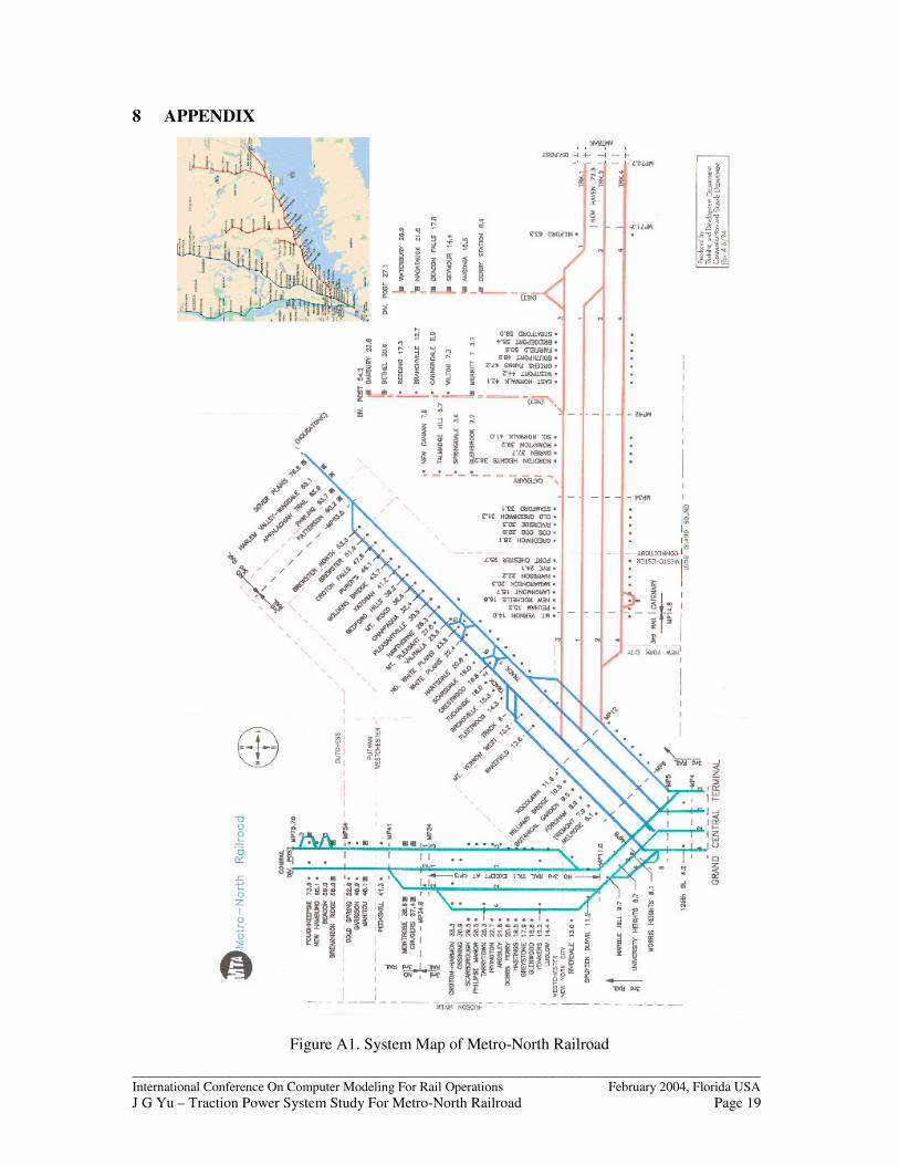
The study is concerned with the electrified portion of the MNR system. The electrified tracks ofthe MNR system consist of three lines: Hudson Line, Harlem Line and New Haven Line. WhileHudson and Harlem lines are in New York State only, the New Haven line serves both New YorkState and Connecticut State. A map of the system is shown in Figure A1 of the Appendix.
All three lines originate north of New York City and converge to reach Grand Central Terminal inthe heart of Manhattan. In addition, AMTRAK operates on a portion of the New Haven Line aspart of the North-East Corridor services. The traction power system is a key element of therailroad’s operations.
Due to historical reasons, the MNR Traction power system comes in two forms: DC and AC.
The DC system uses rectifiers in line-side substations to convert commercial power at 3-phase13kV AC into 700V DC, which is distributed by conductor rails to power the trains. The DCsystem serves both Hudson Line (34 miles of route) and Harlem Line (48 miles of route), plus asmall section of the New Haven Line (3 miles of route). There are about 250 miles of tracks in theDC territory.
The AC system uses transformers in supply-substations to transform commercial power at 3phase 138kV (or 115kV) AC into 26kV AC. Autotransformers in line-side substations furthertransform the 26kV voltage into +13kV/-13kV voltages. These voltages are distributed along thetracks by the overhead catenary system and line-side feeder wires. Trains are powered at 13kVvoltage level. The majority of the New Haven Line (between Pelham and New Haven) plus abranch between Stamford and New Canaan is served by AC power. There are about 250 miles oftracks in the AC territory.
2 DC SYSTEM STUDY
2.1 Load flow modelThe software package that is used to develop the load flow model is the RAILSIM�� Load FlowAnalyzer (DC version). The entire DC system is modeled as a single entity, in the same way thatthe system is configured electrically. The input data for the load flow model is described belowbriefly.
Track data. To start with, the track data is “mapped” into the model. Due to the complexity ofthe track layout, the tracks are divided into segments. These segments are then pieced together toreflect the real connections of the system. Engineering stationing is used to describe the locationsof all entities that are associated with the tracks, in the same way as it is used in engineeringdrawings.

_______________________________________________________________________________________________International Conference On Computer Modeling For Rail Operations February 2004, Florida USAJ G Yu – Traction Power System Study For Metro-North Railroad Page 3
This approach makes the model extremely flexible. There is no limitation on the track topologythat can be modeled. For example, the Grand Central Terminal has two levels with dozens oftracks, which form part of the integral model.
There are many instances when discontinuities in engineering stationing occur. This may becaused by previous line changes, or different conventions in different lines that make up thesystem. Such discontinuities can be accommodated easily.
Train operations. The Year 2002 operating timetable is used as the baseline. Due to the nature ofthe commuter railroad, most trains are unique, since they differ in either train consists and/orstation stop patterns. This demands that each train must be modeled individually. There are over600 trains dispatched from across the system in a typical weekday. Weekends and holidays havedifferent timetables from weekdays.
Yard load. MNR has four yards for train storage, inspection and maintenance for DC poweredtrains. Trains in the yards take a lesser amount of power as they draw “hotel” power to provideheating or air conditioning, and to operate compressors, etc. Based on the operating timetable,each train that enters a particular yard was assigned a power demand figure and time duration forits stay in the yard. A final load table for each yard was derived over a typical 24-hour cycle,including background load in workshop areas that are part of the yard facilities. Saturday, Sundayand holidays were treated separately from weekdays.
Vehicle characteristics. Seven types of electric vehicles currently run on the DC system. Six ofwhich are electric multiple units (EMU) with the type designations of M1a, M3a, ACMU, M2,M4, M6, while one is a dual-mode powered diesel electric-electric locomotive known as the“Genesis”. Between Grand Central and 125th Street, the Genesis locomotive takes power from the3rd rail electrical supply. North of 125th Street, it runs on diesel. A rolling stock database wasestablished, with each type of vehicle having its own characteristics.
Electrical Network. For the electrical network data input, the start point is the electrical singleline diagram. A full diagram was developed for the whole DC system. Individual components ofthe network include: substations and circuit breaker houses, 3rd rail conductors, running rails;feeder connections (both positive and negative), negative reactors, cross-track bondingconnections, etc. A database for all these components was established for inputting into the loadflow model.
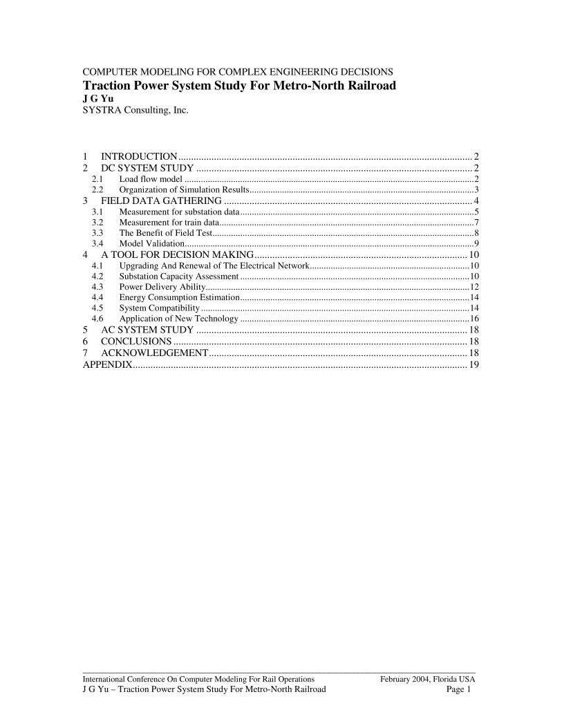
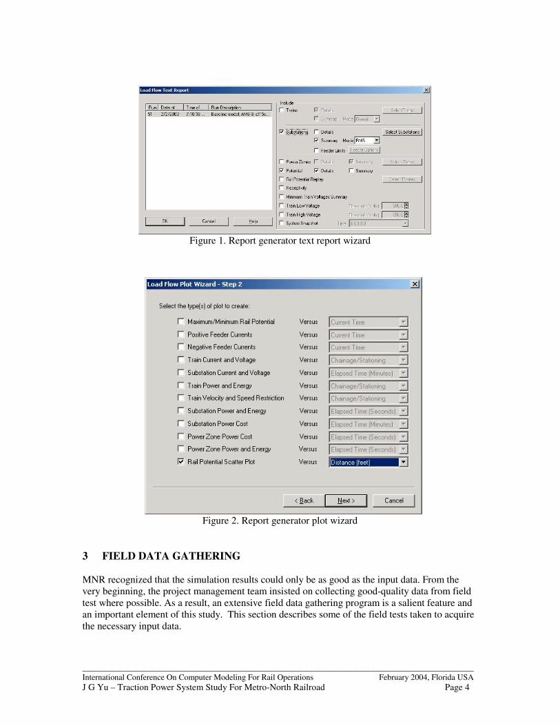
2.2 Organization of Simulation ResultsThe simulation results are stored in binary data files. A dedicated report generator was developedto present the results in both graphical form and numerical form. Both forms of output can beexported to electronic files. These files can be used for report writing and further analysis. Thereport and plot wizards of the report generator are shown in Figure 1 and Figure 2 respectively.
_______________________________________________________________________________________________International Conference On Computer Modeling For Rail Operations February 2004, Florida USAJ G Yu – Traction Power System Study For Metro-North Railroad Page 4
Figure 1. Report generator text report wizard
Figure 2. Report generator plot wizard
3 FIELD DATA GATHERING
MNR recognized that the simulation results could only be as good as the input data. From thevery beginning, the project management team insisted on collecting good-quality data from fieldtest where possible. As a result, an extensive field data gathering program is a salient feature andan important element of this study. This section describes some of the field tests taken to acquirethe necessary input data.
_______________________________________________________________________________________________International Conference On Computer Modeling For Rail Operations February 2004, Florida USAJ G Yu – Traction Power System Study For Metro-North Railroad Page 5
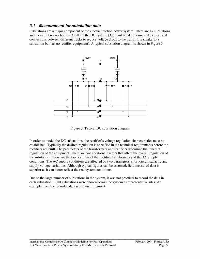
3.1 Measurement for substation dataSubstations are a major component of the electric traction power system. There are 47 substationsand 3 circuit breaker houses (CBH) in the DC system. (A circuit breaker house makes electricalconnections between different tracks to reduce voltage drops to the trains. It is similar to asubstation but has no rectifier equipment). A typical substation diagram is shown in Figure 3.
Figure 3. Typical DC substation diagram
In order to model the DC substations, the rectifier’s voltage regulation characteristics must beestablished. Typically the desired regulation is specified in the technical requirements before therectifiers are built. The parameters of the transformers and rectifiers determine the inherentregulation of the equipment. There are two additional factors that affect the overall regulation ofthe substation. These are the tap positions of the rectifier transformers and the AC supplyconditions. The AC supply conditions are affected by two parameters: short circuit capacity andsupply voltage variations. Although typical figures can be assumed, field measured data issuperior as it can better reflect the real system conditions.
Due to the large number of substations in the system, it was not practical to record the data ineach substation. Eight substations were chosen across the system as representative sites. Anexample from the recorded data is shown in Figure 4.

_______________________________________________________________________________________________International Conference On Computer Modeling For Rail Operations February 2004, Florida USAJ G Yu – Traction Power System Study For Metro-North Railroad Page 6
Figure 4. Derivation of rectifier regulation characteristics from measured data
This figure illustrates that the voltage regulation forms a band rather than a single line. Thisreflects the instantaneous changes in AC supply side conditions. The two solid-lines in the figurerepresent the derived upper and lower limits of the regulation. Usually the average regulationcharacteristic is chosen for the load flow model. In some cases, either the upper or the lower limitmay be more desirable. This is dependent on the particular application that is undertaken.

_______________________________________________________________________________________________International Conference On Computer Modeling For Rail Operations February 2004, Florida USAJ G Yu – Traction Power System Study For Metro-North Railroad Page 7
3.2 Measurement for train dataAll types of trains that run on the DC system were field-tested. Test-trains were run on a sectionof track on the Hudson line. Data was gathered by electronic data recorders and transferred tocomputers for analysis. At the same time, line-side substation data was also recorded in threesubstations that supply the test track. The test track was electrically isolated from the rest of thesystem during the tests. The data recorder setup in one of the tests is shown in Figure 5.
Figure 5. Recorder setup for the measurement of train data
From each test, the test data was analyzed to obtain the calibrated characteristics of these trains.Figure 6 is an example, which shows the derivation of tractive effort curve from the test data.
Figure 6. Calibration of tractive effort from test data
M7 Test A6 - Calculated and Adopted Tractive Effort
0
1000
2000
3000
4000
5000
6000
7000
8000
0 10 20 30 40 50 60 70 80
Speed (mph)
TE
(lb
F/c
ar)
M7 adopted TE at 6500lb limit (Test A6)
Calc.instant.TE from Test #A6 (lb/car)
_______________________________________________________________________________________________International Conference On Computer Modeling For Rail Operations February 2004, Florida USAJ G Yu – Traction Power System Study For Metro-North Railroad Page 8
3.3 The Benefit of Field TestThe field tests were not only used to derive the various parameters that are required by thesimulator. They have also been used as a tool for evaluating current system conditions and forsystem improvement. There were occasions when unforeseen benefits that can be brought by suchtests. This section describes one such example.
Modification of M3a propulsion characteristicsOne of the main indicators for traction power system performance is the train voltage. If a train’svoltage level is healthy, its power demand can be fully met by the traction power system. If atrain’s voltage is too low, its power demand cannot be fully met. As a result, the train cannotaccelerate at the desired acceleration rate, which will cause journey time delays.
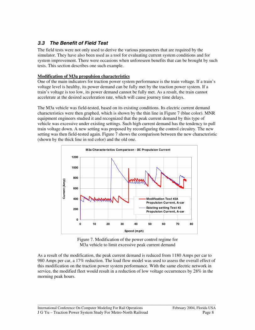
The M3a vehicle was field-tested, based on its existing conditions. Its electric current demandcharacteristics were then graphed, which is shown by the thin line in Figure 7 (blue color). MNRequipment engineers studied it and recognized that the peak current demand by this type ofvehicle was excessive under existing settings. Such high current demand has the tendency to pulltrain voltage down. A new setting was proposed by reconfiguring the control circuitry. The newsetting was then field-tested again. Figure 7 shows the comparison between the new characteristic(shown by the thick line in red color) and the old one.
Figure 7. Modification of the power control regime forM3a vehicle to limit excessive peak current demand
As a result of the modification, the peak current demand is reduced from 1180 Amps per car to980 Amps per car, a 17% reduction. The load flow model was used to assess the overall effect ofthis modification on the traction power system performance. With the same electric network inservice, the modified fleet would result in a reduction of low voltage occurrences by 28% in themorning peak hours.
M3a Characteristics Comparison - DC Propulsion Current
0
200
400
600
800
1000
1200
0 10 20 30 40 50 60 70 80
Speed (mph)
Cu
rren
t (A
mp
)
Modification Test #2APropulsion Current, A-car
Existing setting Test #2Propulsion Current, A-car
_______________________________________________________________________________________________International Conference On Computer Modeling For Rail Operations February 2004, Florida USAJ G Yu – Traction Power System Study For Metro-North Railroad Page 9
Subsequently, MNR decided to modify the control circuits of the whole M3a fleet. The cost ofreconfiguring the vehicle’s control circuits is insignificant compared with upgrading the tractionpower system that can achieve the same performance. The cost saving is apparent.
3.4 Model ValidationThe study underwent a process of verifying the load flow results against utility billing records. Alarge volume of data was provided by the utility company in the form of recorded power demand(kW) for each substation. The utility company billed these by time of day, for 24 hours each day.Altogether, 13 months’ data was made available from January 2002 to January 2003.
A number of load flow simulation runs were then carried out. The results from the load flowmodel were compared against the billed data. Two items of data were compared. These are:
� 30 minute interval peak power demand (in kW) for both summer and winter� Energy consumption (in kWh) for summer months, winter months and a whole year
Both items showed very good agreement between simulated results and the billed data.
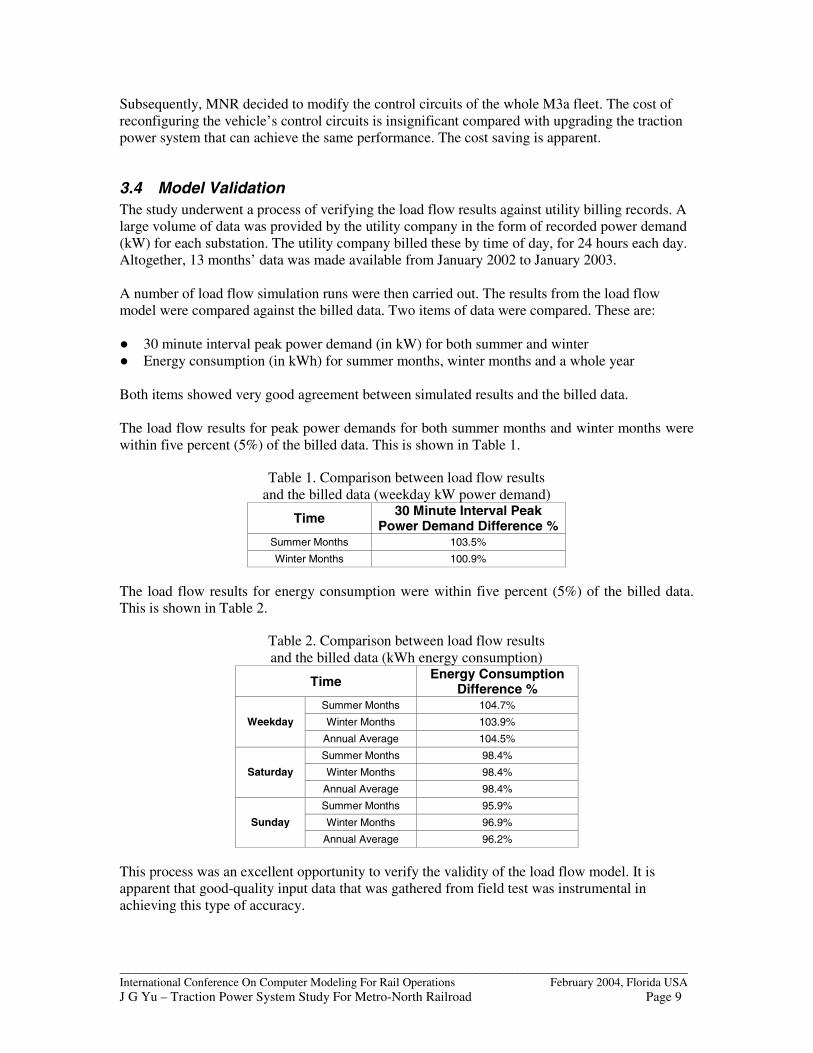
The load flow results for peak power demands for both summer months and winter months werewithin five percent (5%) of the billed data. This is shown in Table 1.
Table 1. Comparison between load flow resultsand the billed data (weekday kW power demand)
Time 30 Minute Interval PeakPower Demand Difference %
Summer Months 103.5%
Winter Months 100.9%
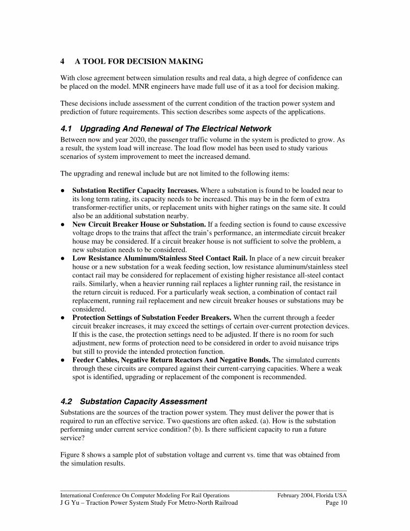
The load flow results for energy consumption were within five percent (5%) of the billed data.This is shown in Table 2.
Table 2. Comparison between load flow resultsand the billed data (kWh energy consumption)
Time Energy ConsumptionDifference %
Summer Months 104.7%
Winter Months 103.9%Weekday
Annual Average 104.5%
Summer Months 98.4%
Winter Months 98.4%Saturday
Annual Average 98.4%
Summer Months 95.9%
Winter Months 96.9%Sunday
Annual Average 96.2%
This process was an excellent opportunity to verify the validity of the load flow model. It isapparent that good-quality input data that was gathered from field test was instrumental inachieving this type of accuracy.
_______________________________________________________________________________________________International Conference On Computer Modeling For Rail Operations February 2004, Florida USAJ G Yu – Traction Power System Study For Metro-North Railroad Page 10
4 A TOOL FOR DECISION MAKING
With close agreement between simulation results and real data, a high degree of confidence canbe placed on the model. MNR engineers have made full use of it as a tool for decision making.
These decisions include assessment of the current condition of the traction power system andprediction of future requirements. This section describes some aspects of the applications.
4.1 Upgrading And Renewal of The Electrical NetworkBetween now and year 2020, the passenger traffic volume in the system is predicted to grow. Asa result, the system load will increase. The load flow model has been used to study variousscenarios of system improvement to meet the increased demand.
The upgrading and renewal include but are not limited to the following items:
� Substation Rectifier Capacity Increases. Where a substation is found to be loaded near toits long term rating, its capacity needs to be increased. This may be in the form of extratransformer-rectifier units, or replacement units with higher ratings on the same site. It couldalso be an additional substation nearby.
� New Circuit Breaker House or Substation. If a feeding section is found to cause excessivevoltage drops to the trains that affect the train’s performance, an intermediate circuit breakerhouse may be considered. If a circuit breaker house is not sufficient to solve the problem, anew substation needs to be considered.
� Low Resistance Aluminum/Stainless Steel Contact Rail. In place of a new circuit breakerhouse or a new substation for a weak feeding section, low resistance aluminum/stainless steelcontact rail may be considered for replacement of existing higher resistance all-steel contactrails. Similarly, when a heavier running rail replaces a lighter running rail, the resistance inthe return circuit is reduced. For a particularly weak section, a combination of contact railreplacement, running rail replacement and new circuit breaker houses or substations may beconsidered.
� Protection Settings of Substation Feeder Breakers. When the current through a feedercircuit breaker increases, it may exceed the settings of certain over-current protection devices.If this is the case, the protection settings need to be adjusted. If there is no room for suchadjustment, new forms of protection need to be considered in order to avoid nuisance tripsbut still to provide the intended protection function.
� Feeder Cables, Negative Return Reactors And Negative Bonds. The simulated currentsthrough these circuits are compared against their current-carrying capacities. Where a weakspot is identified, upgrading or replacement of the component is recommended.
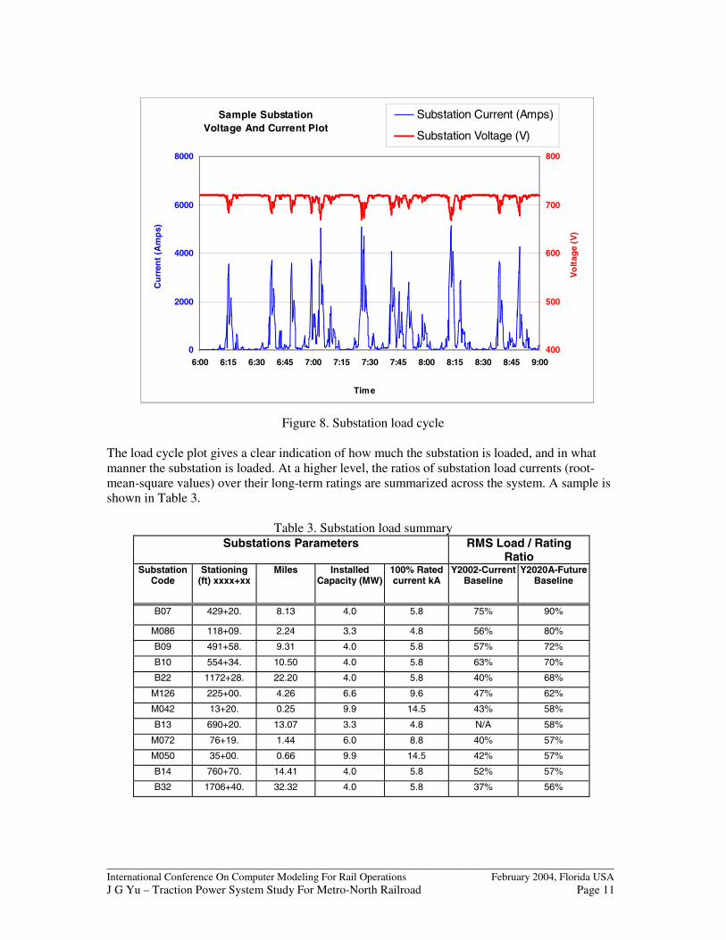
4.2 Substation Capacity AssessmentSubstations are the sources of the traction power system. They must deliver the power that isrequired to run an effective service. Two questions are often asked. (a). How is the substationperforming under current service condition? (b). Is there sufficient capacity to run a futureservice?
Figure 8 shows a sample plot of substation voltage and current vs. time that was obtained fromthe simulation results.
_______________________________________________________________________________________________International Conference On Computer Modeling For Rail Operations February 2004, Florida USAJ G Yu – Traction Power System Study For Metro-North Railroad Page 11
Figure 8. Substation load cycle
The load cycle plot gives a clear indication of how much the substation is loaded, and in whatmanner the substation is loaded. At a higher level, the ratios of substation load currents (root-mean-square values) over their long-term ratings are summarized across the system. A sample isshown in Table 3.
Table 3. Substation load summarySubstations Parameters RMS Load / Rating
RatioSubstation
CodeStationing
(ft) xxxx+xxMiles Installed
Capacity (MW)100% Ratedcurrent kA
Y2002-CurrentBaseline
Y2020A-FutureBaseline
B07 429+20. 8.13 4.0 5.8 75% 90%
M086 118+09. 2.24 3.3 4.8 56% 80%
B09 491+58. 9.31 4.0 5.8 57% 72%
B10 554+34. 10.50 4.0 5.8 63% 70%
B22 1172+28. 22.20 4.0 5.8 40% 68%
M126 225+00. 4.26 6.6 9.6 47% 62%
M042 13+20. 0.25 9.9 14.5 43% 58%
B13 690+20. 13.07 3.3 4.8 N/A 58%
M072 76+19. 1.44 6.0 8.8 40% 57%
M050 35+00. 0.66 9.9 14.5 42% 57%
B14 760+70. 14.41 4.0 5.8 52% 57%
B32 1706+40. 32.32 4.0 5.8 37% 56%
Sample Substation Voltage And Current Plot
0
2000
4000
6000
8000
6:00 6:15 6:30 6:45 7:00 7:15 7:30 7:45 8:00 8:15 8:30 8:45 9:00
Time
Cu
rren
t (A
mp
s)
400
500
600
700
800
Vo
ltag
e (V
)
Substation Current (Amps)
Substation Voltage (V)

_______________________________________________________________________________________________International Conference On Computer Modeling For Rail Operations February 2004, Florida USAJ G Yu – Traction Power System Study For Metro-North Railroad Page 12
This table shows in descending order the most heavily loaded substations for a future servicescenario. This type of summary gives a panoramic view of the predicted load conditions for allsubstations in the system.
Table 3 indicates that some of the substations will have high utilization ratios in the Y2020Ascenario. Reinforcements for these areas are recommended.
Similar load summaries can be made for all current-carrying components, including feeder cables,negative reactors, conductor rails, etc. Short-term peak loads are summarized in a similar manner.
4.3 Power Delivery AbilityWith adequate capacity established for the substations, the traction power system must havesufficient delivery ability to transmit the power to the trains. Power is transmitted through the 3rd
rail and the running rails.
Figure 9 shows a sample plot of train voltage and current vs. location from simulation results, asthe train moves along the track.
Figure 9. Train voltage and current plot
As this figure shows, the voltage at a train can drop significantly in some locations. This is anindication of weak spots in the power delivery network. All such weak spots need to be found outacross the whole system.
At a higher level, a scattered plot of all train’s low voltage occurrences was developed from thesimulation results for this purpose. This type of plot serves as an indicator of the power deliveryability of the traction power system (or the inability to deliver power in certain weak areas).
Sample Train Voltage And Current PlotTrain #615_HA (7:49AM)
50th
St.
SS
CB
H
42nd
St.
SS
72nd
St.
SS
86th
St.
SS
110t
h S
t. S
S
126t
h S
t. S
SC
BH
Mot
t Hav
en
Mel
rose
Tre
mon
t
Bot
anic
al G
arde
n
Will
iam
s B
ridge
Woo
dlaw
n
Fle
etw
ood
Tuc
kaho
e
Leew
ood
Sca
rsda
le
Har
tsda
le
Whi
te P
lain
s
NW
P S
outh
NW
P N
orth
Ken
sico
Tho
rnw
ood
Cha
ppaq
ua
Mt K
isco
Bed
ford
Hill
s
Duf
fys
Brid
ge
0
2000
4000
6000
8000
10000
12000
14000
16000
Substations (Geographical Order)
Cu
rren
t (A
mp
s)
0
100
200
300
400
500
600
700
800
Vo
ltag
e (V
)
Substations
Train Current
Train Voltage

_______________________________________________________________________________________________International Conference On Computer Modeling For Rail Operations February 2004, Florida USAJ G Yu – Traction Power System Study For Metro-North Railroad Page 13
Figure 10 shows an example. This is a scattered plot for all occurrences when train voltage fallsbelow 500V on a section of the Harlem Line under a simulated operating scenario. Below 500V,train performance starts to degrade.
Figure 10. Scattered plot for train low voltage occurrences
The data shown in the scattered plots are then summarized. Table 4 gives a comparison of alloccurrences when train voltages fall below 500V under several simulated scenarios.
Table 4. Summaries for the number of train voltage occurrences below 500VLine Scenario A Scenario B - With
one SubstationOutage
Scenario C Scenario D
Harlem line 655 790 178 51
Hudson line 348 348 137 30
New Haven line 2 2 2 2
Total 1005 1140 317 83
After the weak areas are identified, appropriate enhancement measures can be considered tomitigate or eliminate such weakness.
The primary factors that determine the power delivery ability of the electrical network are the no-load voltages in substations, spacing between substations and the resistivity of the 3rd rail and therunning rails.
Train Voltages Below 500V - A Section of Harlem Line
987
0
100
200
300
400
500
600
Location (milepost)
Vo
ltag
e (V
)
Train Voltages Below 500V
Milepost
Substations
B07
- T
rem
on
t
B09
-Bo
tan
ic
Gar
den
s
Cla
rem
on
t C
BH
B06
- M
elro
se
B10
-Will
iam
s B
rid
ge
Wo
od
law
nC
BH
B11
-
10 11
_______________________________________________________________________________________________International Conference On Computer Modeling For Rail Operations February 2004, Florida USAJ G Yu – Traction Power System Study For Metro-North Railroad Page 14
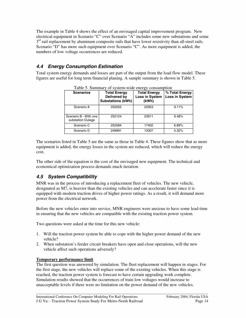
The example in Table 4 shows the effect of an envisaged capital improvement program. Newelectrical equipment in Scenario “C” over Scenario “A” includes some new substations and some3rd rail replacement by aluminum composite rails that have lower resistivity than all-steel rails.Scenario “D” has more such equipment over Scenario “C”. As more equipment is added, thenumbers of low voltage occurrences are reduced.
4.4 Energy Consumption EstimationTotal system energy demands and losses are part of the output from the load flow model. Thesefigures are useful for long term financial planing. A sample summary is shown in Table 5.
Table 5. Summary of system-wide energy consumptionScenarios Total Energy
Delivered bySubstations (kWh)
Total EnergyLoss in System
(kWh)
% Total EnergyLoss in System
Scenario A 252055 22953 9.11%
Scenario B - With onesubstation Outage
252124 23911 9.48%
Scenario C 252584 17402 6.89%
Scenario D 249991 13307 5.32%
The scenarios listed in Table 5 are the same as those in Table 4. These figures show that as moreequipment is added, the energy losses in the system are reduced, which will reduce the energycost.
The other side of the equation is the cost of the envisaged new equipment. The technical andeconomical optimization process demands much iteration.
4.5 System CompatibilityMNR was in the process of introducing a replacement fleet of vehicles. The new vehicle,designated as M7, is heavier than the existing vehicles and can accelerate faster since it isequipped with modern traction drives of higher power ratings. As a result, it will demand morepower from the electrical network.
Before the new vehicles enter into service, MNR engineers were anxious to have some lead-timein ensuring that the new vehicles are compatible with the existing traction power system.
Two questions were asked at the time for this new vehicle:
1. Will the traction power system be able to cope with the higher power demand of the newvehicle?
2. When substation’s feeder circuit breakers have open and close operations, will the newvehicle affect such operations adversely?
Temporary performance limitThe first question was answered by simulation. The fleet replacement will happen in stages. Forthe first stage, the new vehicles will replace some of the existing vehicles. When this stage isreached, the traction power system is forecast to have certain upgrading work complete.Simulation results showed that the occurrences of train low voltages would increase tounacceptable levels if there were no limitation on the power demand of the new vehicles.
_______________________________________________________________________________________________International Conference On Computer Modeling For Rail Operations February 2004, Florida USAJ G Yu – Traction Power System Study For Metro-North Railroad Page 15
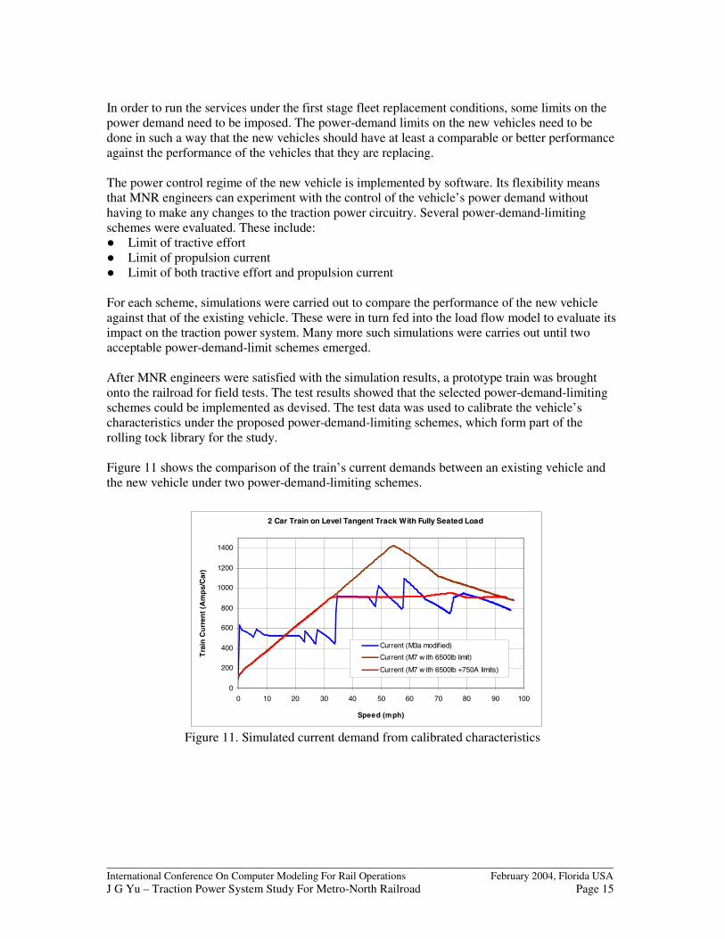
In order to run the services under the first stage fleet replacement conditions, some limits on thepower demand need to be imposed. The power-demand limits on the new vehicles need to bedone in such a way that the new vehicles should have at least a comparable or better performanceagainst the performance of the vehicles that they are replacing.
The power control regime of the new vehicle is implemented by software. Its flexibility meansthat MNR engineers can experiment with the control of the vehicle’s power demand withouthaving to make any changes to the traction power circuitry. Several power-demand-limitingschemes were evaluated. These include:� Limit of tractive effort� Limit of propulsion current� Limit of both tractive effort and propulsion current
For each scheme, simulations were carried out to compare the performance of the new vehicleagainst that of the existing vehicle. These were in turn fed into the load flow model to evaluate itsimpact on the traction power system. Many more such simulations were carries out until twoacceptable power-demand-limit schemes emerged.
After MNR engineers were satisfied with the simulation results, a prototype train was broughtonto the railroad for field tests. The test results showed that the selected power-demand-limitingschemes could be implemented as devised. The test data was used to calibrate the vehicle’scharacteristics under the proposed power-demand-limiting schemes, which form part of therolling tock library for the study.
Figure 11 shows the comparison of the train’s current demands between an existing vehicle andthe new vehicle under two power-demand-limiting schemes.
Figure 11. Simulated current demand from calibrated characteristics
2 Car Train on Level Tangent Track With Fully Seated Load
0
200
400
600
800
1000
1200
1400
0 10 20 30 40 50 60 70 80 90 100
Speed (mph)
Tra
in C
urr
ent
(Am
ps/
Car
)
Current (M3a modif ied)
Current (M7 w ith 6500lb limit)
Current (M7 w ith 6500lb +750A limits)
_______________________________________________________________________________________________International Conference On Computer Modeling For Rail Operations February 2004, Florida USAJ G Yu – Traction Power System Study For Metro-North Railroad Page 16
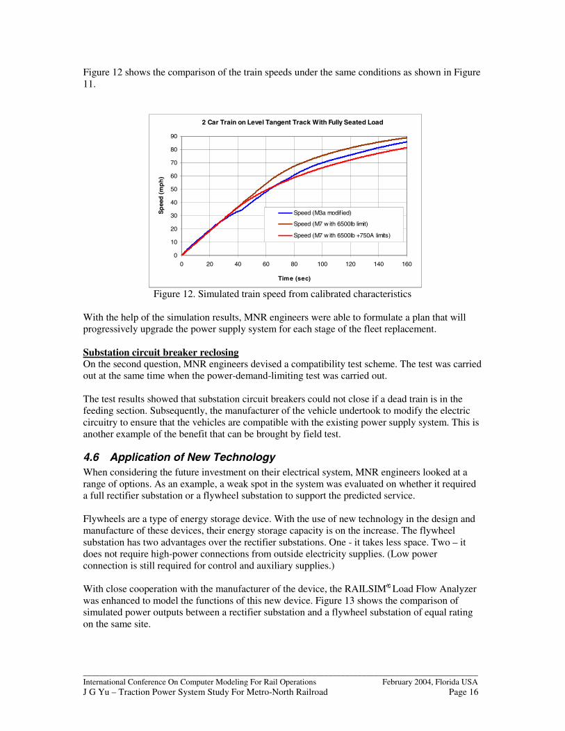
Figure 12 shows the comparison of the train speeds under the same conditions as shown in Figure11.
Figure 12. Simulated train speed from calibrated characteristics
With the help of the simulation results, MNR engineers were able to formulate a plan that willprogressively upgrade the power supply system for each stage of the fleet replacement.
Substation circuit breaker reclosingOn the second question, MNR engineers devised a compatibility test scheme. The test was carriedout at the same time when the power-demand-limiting test was carried out.
The test results showed that substation circuit breakers could not close if a dead train is in thefeeding section. Subsequently, the manufacturer of the vehicle undertook to modify the electriccircuitry to ensure that the vehicles are compatible with the existing power supply system. This isanother example of the benefit that can be brought by field test.
4.6 Application of New TechnologyWhen considering the future investment on their electrical system, MNR engineers looked at arange of options. As an example, a weak spot in the system was evaluated on whether it requireda full rectifier substation or a flywheel substation to support the predicted service.
Flywheels are a type of energy storage device. With the use of new technology in the design andmanufacture of these devices, their energy storage capacity is on the increase. The flywheelsubstation has two advantages over the rectifier substations. One - it takes less space. Two – itdoes not require high-power connections from outside electricity supplies. (Low powerconnection is still required for control and auxiliary supplies.)
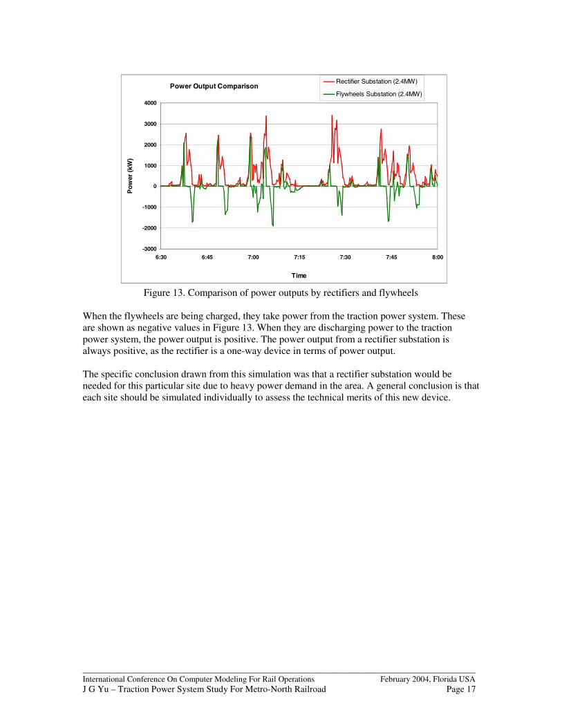
With close cooperation with the manufacturer of the device, the RAILSIM�� Load Flow Analyzerwas enhanced to model the functions of this new device. Figure 13 shows the comparison ofsimulated power outputs between a rectifier substation and a flywheel substation of equal ratingon the same site.
2 Car Train on Level Tangent Track With Fully Seated Load
0
10
20
30
40
50
60
70
80
90
0 20 40 60 80 100 120 140 160
Time (sec)
Sp
eed
(m
ph
)
Speed (M3a modif ied)
Speed (M7 w ith 6500lb limit)
Speed (M7 w ith 6500lb +750A limits)
_______________________________________________________________________________________________International Conference On Computer Modeling For Rail Operations February 2004, Florida USAJ G Yu – Traction Power System Study For Metro-North Railroad Page 17
Figure 13. Comparison of power outputs by rectifiers and flywheels
When the flywheels are being charged, they take power from the traction power system. Theseare shown as negative values in Figure 13. When they are discharging power to the tractionpower system, the power output is positive. The power output from a rectifier substation isalways positive, as the rectifier is a one-way device in terms of power output.
The specific conclusion drawn from this simulation was that a rectifier substation would beneeded for this particular site due to heavy power demand in the area. A general conclusion is thateach site should be simulated individually to assess the technical merits of this new device.
Power Output Comparison
-3000
-2000
-1000
0
1000
2000
3000
4000
6:30 6:45 7:00 7:15 7:30 7:45 8:00
Time
Pow
er (k
W)
Rectifier Substation (2.4MW)
Flywheels Substation (2.4MW)

_______________________________________________________________________________________________International Conference On Computer Modeling For Rail Operations February 2004, Florida USAJ G Yu – Traction Power System Study For Metro-North Railroad Page 18
5 AC SYSTEM STUDYThe AC system model is currently under construction. The development for the AC model takesthe same approach as the DC system model. At the time of publication of this paper, extensivefield-testing has been carried out to gather the necessary data.
Substation Data Gathering. This includes all of the four supply substations (138kV or 115kV)and three of the intermediate autotransformer substations.
Train Data Gathering. All EMUs operating on the AC portion of the railroad have been tested(M2, M4 and M6). All Amtrak rolling stock types have been tested (AEM7 DC Drives, AEM7AC Drives, HHP, ACELA trainset).
AC Load Flow Model. The software package that is used to develop the load flow model is theRAILSIM�� Load Flow Analyzer (AC version). The entire AC system will be modeled as a singleentity, in the same way as the system is configured.
6 CONCLUSIONSThe RAILSIM��
� load flow model has proven to be a very useful tool in the traction power systemstudy for Metro-North Railroad.
The usefulness of the load flow model has been greatly enhanced by using field test data, and thevalidation of the simulation results against real world data.
Close coordination with the Metro-North Railroad staff has made the study fruitful.
7 ACKNOWLEDGEMENTThe author would like to thank Mike Savchak, John Kesich, Jim Gillies, Jim Pepitone, RobertWalker, Alex Bunin and Artie Smith of MNR; Fred Chojnicki of Connecticut Department ofTransportation; Tom Pyle, George Binns, Tammy Krause, Gus Gramelis and Ben Allen ofAmtrak; Sarma Hota, Bill Lipfert and Daren Petroski of SYSTRA for their contributions. Manyother individuals have contributed to the Traction Power System Study effort. The authorgratefully acknowledges their teamwork as well.
The viewpoints expressed in this paper are entirely the authors and are not those of either Metro-North Railroad or of SYSTRA Consulting, Inc. or the individuals mention above.
_______________________________________________________________________________________________International Conference On Computer Modeling For Rail Operations February 2004, Florida USAJ G Yu – Traction Power System Study For Metro-North Railroad Page 19
8 APPENDIX
Figure A1. System Map of Metro-North Railroad

_______________________________________________________________________________________________International Conference On Computer Modeling For Rail Operations February 2004, Florida USAJ G Yu – Traction Power System Study For Metro-North Railroad Page 20
International Conference On Computer Modeling For Rail OperationsFebruary 2004, Florida USA
Title of Paper: ”Traction Power System Study For Metro-North Railroad”Author: J. Gordon Yu
Author’s Biographical Information
Gordon Yu graduated with a B.Sc. in Electrical Engineering from the Southwest Jiao-TongUniversity in China. After a few years of work in the railway industry both in China and in theUK, he went back to university and obtained his Ph.D. in Electrical Engineering from theUniversity of Birmingham in the UK.
He has been working for SYSTRA Consulting, Inc. as a Senior Rail Operations Analyst over thelast three and half years. His specialty field of work is in the traction power systems, whichinvolves both simulation software development and applications.
In addition to his work on the Metro-North Railroad Traction Power Study project, he has alsostudied the NJ TRANSIT traction power systems for both the North Jersey Coast Line, and theMorris & Essex Line.
He has provided training courses for RAILSIM� users, including San Diego Metropolitan TransitDevelopment Board (MTDB), Land Transport Authority (LTA) of Singapore and WashingtonGroup International, New Jersey.
Before he joined SYSTRA, he had worked for WS Atkins Rail Ltd, ALSTOM Power ConversionLtd and Balfour Beatty Rail Projects Ltd., all in the UK.
There he was involved in design and study of some major railway electrification projects,including:
� Mass Transit Railway Company (MTRC) of Hong Kong – for Lantau & Airport Railwayproject;
� Network Rail (Railtrack) – for west-coast mainline electrification upgrade;� London Underground Ltd – for Jubilee Line Extension Project� Ankara Metro,Turkey,� Manchester Metrolink,UK� British Columbia Transit Skytrain System, Canada
He has presented a dozen technical papers in conferences on the subject of traction powersystems.