tracking strategy for sid
DESCRIPTION
Tracking Strategy for SiD. Marcel Demarteau Fermilab For the SiD Tracking Group. Tracking Review ILC Detector R&D Panel Feb. 4-8, 2007, Beijing. ZH → mm H ~3700 evts/500 fb -1. ILC Physics Characteristics. Machine design luminosity L = 2 x 10 34 cm -2 s -1 ( √s = 500 GeV) - PowerPoint PPT PresentationTRANSCRIPT

Marcel DemarteauFermilab
For the SiD Tracking Group
Tracking Review ILC Detector R&D Panel
Feb. 4-8, 2007, Beijing
Tracking Review ILC Detector R&D Panel
Feb. 4-8, 2007, Beijing
Tracking Strategy Tracking Strategy for SiDfor SiD

Tracking R&D Review, Feb. 5-8, 2007, Beijing, -- M. Demarteau Slide 2
ILC Physics CharacteristicsILC Physics CharacteristicsEven
ts/5
00
fb-1
500
5000
ZH ZH →→H H ~3700 ~3700
evts/500 fbevts/500 fb-1-1
ZH ZH →→H H ~3700 ~3700
evts/500 fbevts/500 fb-1-1
Machine design luminosity L = 2 x 1034 cm-2s-1 (√s = 500 GeV)
Processes through s-channel spin-1 exchange: ~ 1/s
Cross sections relatively democratic
Cross sections are small Angular distribution: (1 + cos2
Premium on forward region Hermetic detectors
Relatively large backgrounds 100k e+e- - pairs per bunch crossing
W and Z bosons in all decay modes become the main objects to reconstruct
Discriminate W and Z in hadronic decay mode
Highly polarized e- beam: ~ 80% To employ discriminating power
requires running at both polarities
Every event counts !

Tracking R&D Review, Feb. 5-8, 2007, Beijing, -- M. Demarteau Slide 3
Polarization at the ILCPolarization at the ILC
Highly polarized e- beam: ~ 80%
Analyzing power of Scan in center of mass energy Various unique Asymmetries
Forward-backward asymmetry Left-Right Asymmetry
Example: Model with extra dimensions Coupling of graviton in 4-dimensions proportional to /M4
D Largest effects for b-quarks
√s = 500 GeV, MD = 2 TeV
Pe = 0.8, L = 1 ab-1
Sensitivity is in the far backward region No sensitivity for leptonic final states (Ae = 0.15)
Hermetic detectors with uniform strengths Importance of forward regions b/c tagging and quark identification in forward region
cos)(2)cos1()1(
8
3
cos2
feeeetot
ff
ff
d
dAPAAP
AfVf
AfVff gg
gg22
2
A 94.0bA 67.0cA 15.0lA
Tracking R&D Review, Feb. 5-8, 2007, Beijing, -- M. Demarteau Slide 4
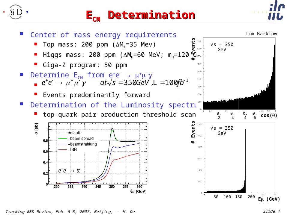
EECM CM DeterminationDetermination
Center of mass energy requirements Top mass: 200 ppm (Mt=35 Mev)
Higgs mass: 200 ppm (MH=60 MeV; mH=120 GeV) Giga-Z program: 50 ppm
Determine ECM from e+e- → +- Events predominantly forward
Determination of the Luminosity spectrum top-quark pair production threshold scan
1100,350 fbGeVsatee L
# E
ve
nts
# E
ve
nts
cos()cos()
# E
ve
nts
# E
ve
nts
E(GeV)E(GeV)
ttee
Tim BarklowTim Barklow
0.2 0.4 0.4 0.6
100 15050 200
√s = 350 GeV
√s = 350 GeV

Tracking R&D Review, Feb. 5-8, 2007, Beijing, -- M. Demarteau Slide 5
EECM CM DeterminationDetermination
Momentum resolution parametrization
Three options considered Angles from +- only EZ: Z → +-
E: e+e- → +- with +/- each the full beam energy
Large sensitivity to MS term 40% increase for x2 increase
in b. Good momentum resolution
and low mass tracker requiredover full angular region
sin2TT
T
p
ba
p
p
angles only
5 3 10 or 10a b
2 sint
t t
p ba
p p
EZ SiD
E SiD
3
E vs
1 10
Z a
b
3
E vs
1 10
a
b
5
E vs
2 10
Z b
a
E vs b
EC
M (
MeV
)E
CM (
MeV
)
Tim BarklowTim Barklow
Tracking R&D Review, Feb. 5-8, 2007, Beijing, -- M. Demarteau Slide 6
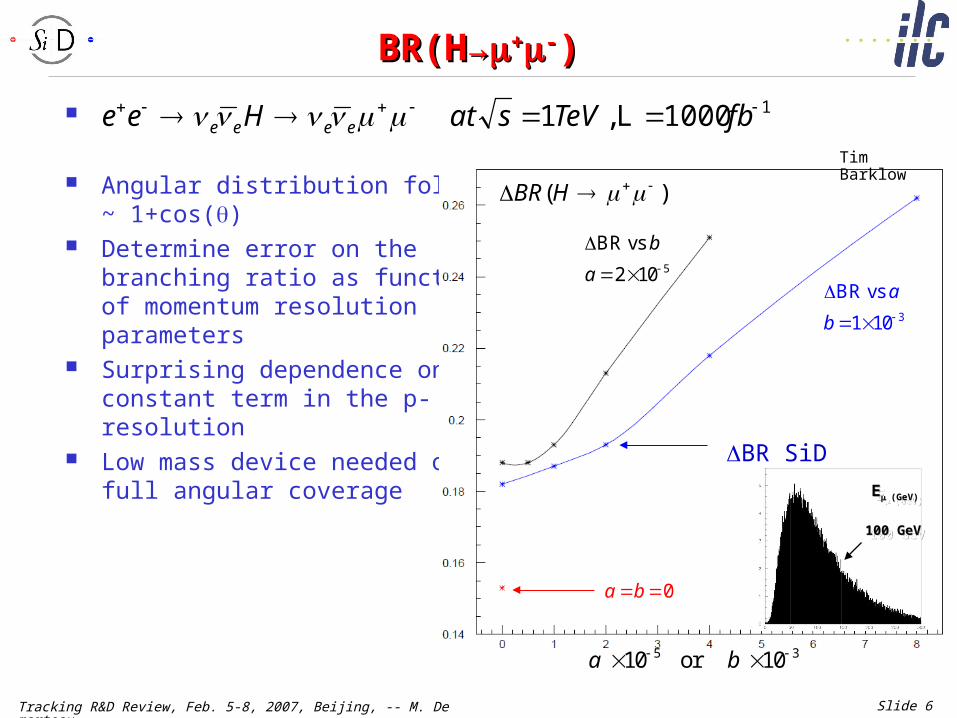
BR(HBR(H→→++--))
Angular distribution follows~ 1+cos()
Determine error on the branching ratio as function of momentum resolution parameters
Surprising dependence on constant term in the p-resolution
Low mass device needed overfull angular coverage
11000,1 fbTeVsatHee eeee L
5 3 10 or 10a b
2 sint
t t
p ba
p p
BR SiD
3
BR vs
1 10
a
b
5
BR vs
2 10
b
a
0a b
EE(GeV)(GeV)EE(GeV)(GeV)
100 GeV100 GeV100 GeV100 GeV
)( HBR
Tim BarklowTim Barklow

Tracking R&D Review, Feb. 5-8, 2007, Beijing, -- M. Demarteau Slide 7
Slepton Mass DeterminationSlepton Mass Determination
Selectron pair production at √s = 1 TeV , ,
Angular distribution follows 1+cos()
Selectron mass determination from Energy end-point spectrum
Benefits significantly from larger angular coverage
Benefits from improved momentum resolution
Slepton Mass Error
0.000
0.050
0.100
0.150
0.200
0.250
-0.10% 0.10% 0.30% 0.50% 0.70% 0.90% 1.10%
Beam Energy Spread
Del
ta(m
) (G
eV) SiD, cos(th) 0-1
Perfect, cos(th) 0-1
SiD, cos(th) 0-0.8
Perfect, cos(th) 0-0.8
GeVme 143 GeVm 1.96 %80eP
Energy Distribution
0
50
100
150
200
250
300
350
400
450
0 9 18
27
36
45
54
63
72
81
90
99
108
117
126
135
144
153
162
171
180
189
198
207
216
225
234
243
252
261
270
279
288
Energy (GeV)
Co
un
ts
Bruce Schumm Bruce Schumm

Tracking R&D Review, Feb. 5-8, 2007, Beijing, -- M. Demarteau Slide 8
Higgs Recoil MassHiggs Recoil Mass
Benchmark measurement is the measurement of the Higgs recoil mass in the channel e+e- → ZH
Higgs recoil mass resolution improves until ∆p/p2 ~ 2 x 10⁻⁵
Sensitivity to invisible Higgs decays, and purity of recoil-tagged Higgs sample, improve accordingly.
Example: s = 300 GeV 500 fb-1
beam energy spread of 0.1% Goal:
Mll < 0.1x
dominated by beamstrahlung

Tracking R&D Review, Feb. 5-8, 2007, Beijing, -- M. Demarteau Slide 9
BackgroundsBackgrounds
“At the ILC the initial state is well defined …”
Backgrounds from the IP Disrupted beams
Extraction line losses Beamstrahlung photons e+e- - pairs
Backgrounds from the machine Muon production at collimators Synchrotron radiation Neutrons from dumps,
extraction lines
Monte Carlo simulations have reached very good predictive power, but one ought to be prepared for the unexpected
A silicon based tracker has single bunch timing resolution
s (GeV) Beam# e+e- per BX
Total Energy (TeV)
500Nomina
l 98 K 197
1000Nomina
l 174 K 1042
For beam current of I=2.8 1014 s-1
0.1% of particles hits spoiler <Nμ> = 4.6 cm-2 sec-1 ,
<Nγ> = 4.7 cm-2 sec-1 For 150 bunches, <Nμ> = 0.0489 cm-
2 or 8855 muons in the tunnel aperture
Alleviated by muon spoilers in tunnel

Tracking R&D Review, Feb. 5-8, 2007, Beijing, -- M. Demarteau Slide 10
Material BudgetMaterial Budget
Material budget, especially in the forward region, is a major issue Babar: 5 layers of double-sided Si Stays below 4% at normal incidence traversing SVT;
average of 0.8% X0 per layer But, significant amount of material (far too much) in forward region
LHC type detectors would be inadequate
ATLAS
ServicesTrTSi StripsPixelsBeampipe
2
1.5
1
0.5
0
X/X
0
-4 -2 0 2 4
BaBar

Tracking R&D Review, Feb. 5-8, 2007, Beijing, -- M. Demarteau Slide 11
Tracking StrategiesTracking Strategies
Many experiments have come up with quite different tracking strategies
What drives the determination of the tracking strategy? What are the external constraints? DØDØ
CMSBaBar

Tracking R&D Review, Feb. 5-8, 2007, Beijing, -- M. Demarteau Slide 12
SiD Design ConceptSiD Design Concept
Detector is conceived as an integrated detector Vertex detector for track seeding and initial pattern recognition Momentum measurement in tracker Integration with calorimeter
Detector design premises: Expect best performance with uniform
technology throughout the detector Silicon and carbon fiber support allows
for uniform transparency of the detector over full angular range (~0.8% X0 per layer)
Silicon and carbon fiber support allows for easy optimization of the design
Silicon provides for superior momentum resolution 2 10-5 (GeV-1)
Silicon provides for single bunch crossing timing Robust against (unforeseen) beam backgrounds and beam induced
backgrounds Retains stand-alone tracking capability

Tracking R&D Review, Feb. 5-8, 2007, Beijing, -- M. Demarteau Slide 13
Concluding RemarksConcluding Remarks
SiD tracker conceived as integral part of the full detector Basic premise is that a silicon based tracker is the most promising
technology that can address the issues facing a linear collider detector The R&D that is needed for the design, and to further optimize it, will
be covered in the subsequent talks Mechanical Design and R&D – Bill Cooper Sensor and Module Design and R&D -- Tim Nelson SiD-related University R&D -- Rich Partridge
R&D Goals: Establish feasibility of current design both mechanical, detector and
readout Develop and demonstrate feasibility of various approaches to tracker design Optimize design with benchmark physics processes
This review is a review of the tracker sub-system R&D only The interplay between vertex detector, tracker, calorimeter and the
implications of the tracker on, for example, particle flow calorimetry, is not quantified.