tracker thermal control system 1 ams tracker thermal control system (ttcs) ttcs design description...
TRANSCRIPT
1
Tracker Thermal Control System
AMS Tracker Thermal Control AMS Tracker Thermal Control System (TTCS)System (TTCS)
TTCS Design DescriptionTTCS Design DescriptionNLR-team: J. van Es, M.P.A.M. Brouwer, B. Verlaat (NIKHEF), A. Pauw, G. van
Donk, T. Zwartbol, CAM. Rens, SM. BardetSun Yat-Sen University team: ZH. He, KH. Guo, JQ. Ni, SS. Lu, XZ. Wang, XM.
Qi, TX. Li, YH Huang INFN-AMS-team: R. Batiston, M. Menichelli et al.

2
Tracker Thermal Control System
Wake heat pipe radiator
Ram heat pipe radiator
TTCS com-ponent box
Condensers
Evaporator• Requirements summary
• System Lay-out & Operation
• Tube routing & condenser
• TTCS-Boxes
• Components
– Pump
– Heat exchanger
– OHP
• Safety approach
• Design challenges
• Integration
ContentsContents

3
Tracker Thermal Control System
Requirements SummaryRequirements SummarySilicon wafer thermal requirements Hybrid circuit thermal requirements Operating temperature: Operating temperature: -10˚C / +25˚C -10˚C / +25˚C Survival temperature: Survival temperature: -20˚C / +40˚C -20˚C / +40˚C Temperature stability: Temperature stability: 3˚C per orbit 3˚C per orbit Maximum allowed gradient between any silicon: 10.0˚C Dissipated heat: Dissipated heat: 2.0 W EOL 144 W total (±10%)
0.75 W per hybrid pair (S=0.47 W, K=0.28 W)

4
Tracker Thermal Control System
TTCS Fluid temperature ranges • Operating Temperature loop (set-point): -15˚C / +15˚C
Loop temperatures in the single-phase part can be -40˚C / +15˚C
• Survival temperature: -100 ˚C / +65˚C (also for internal pressure)
• Start-up temperature: -40 ˚C / + 20˚C (accumulator start-up
temperature)
Requirements SummaryRequirements Summary

5
Tracker Thermal Control System
TTCE (Electronics) in TTCS-boxes
• Operating temperature: -20˚C / +85˚C
• Survival temperature: -40˚C / +105˚C
TTCS-box interface with USS
• Operating temperature: -40˚C / +55˚C
• Survival temperature: -40˚C / +55˚C
• Start-up temperature (driving requirement): -40 ˚C / 10 ˚C
Requirements SummaryRequirements Summary
6
Tracker Thermal Control System
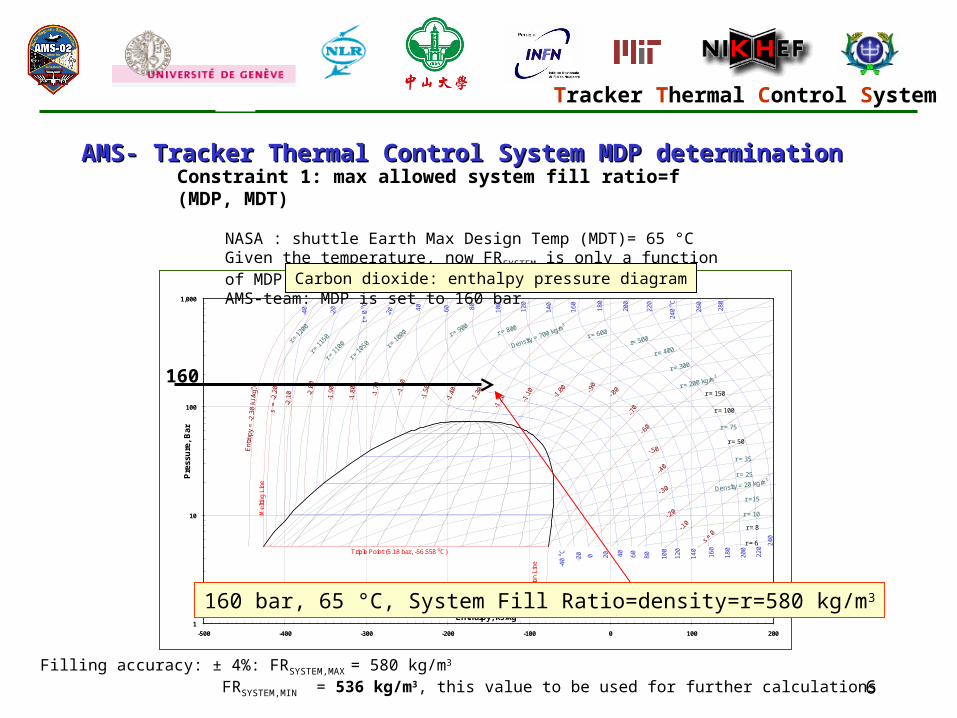
AMS- Tracker Thermal Control System MDP determinationAMS- Tracker Thermal Control System MDP determinationConstraint 1: max allowed system fill ratio=f (MDP, MDT)
NASA : shuttle Earth Max Design Temp (MDT)= 65 °CGiven the temperature, now FRSYSTEM is only a function of MDPAMS-team: MDP is set to 160 bar
Carbon Dioxide: Pressure - Enthalpy Diagram
Mel
ting
Line
-40
-40
oC
-20
-20
t = 0
oC
0
20
20
40
40
60
60
80
80
100
100
120
120
140
140
160
160
180
180
200
200
220
220
240
oC
240
260
280
Ent
ropy
= -
2.3
0 k
J/kg
,o C
s =
-2
.20
-2.1
0 -2.0
0
-1.9
0
-1.8
0
-1.7
0
--1.
60
-1.5
0
-1.4
0
-1.3
0
-1.2
0 -1.1
0
-1.0
0
-.70
-.90
-.80
-.60
-.50
-.40
-.30
-.20
-.10
s =
0S
ublim
atio
n Li
ne
Triple Point (5.18 bar, -56.558 oC)
r = 1
200
r = 1
150
r = 1
100
r = 1
050 r =
100
0 r = 900
r = 800
Density = 700 kg/m3
r = 600
r= 500
r = 400
r = 300
r = 200 kg/m3
r = 150
r = 100
r = 75
r = 50
r = 35
Density = 20 kg/m3
r = 10
r = 25
r =15
r = 8
r = 6
1
10
100
1,000
-500 -400 -300 -200 -100 0 100 200
Enthalpy, kJ/kg
Pre
ssu
re,
Bar
Copyright © 1999 ChemicaLogic Corporation
www.chemicalogic.com160 bar, 65 °C, System Fill Ratio=density=r=580 kg/m3
Carbon dioxide: enthalpy pressure diagram
160
Filling accuracy: ± 4%: FRSYSTEM,MAX = 580 kg/m3
FRSYSTEM,MIN = 536 kg/m3, this value to be used for further calculations

7
Tracker Thermal Control System
Requirements SummaryRequirements Summary
TTCS design pressures TTCS components MDP [bar] Proof pressure [bar] Burst pressure [bar]
Evaporator tubing 160 240 640
Tubing in TTCS-P-box & TTCS-S box
160 240 640
TTCS-components - valves - pumps - APS - DPS - LFM - Accumulator - connection construction condenser lines
160 240 400
Condenser (proposed)* 3000 (TBC) 3500 (TBC) TBD
8
Tracker Thermal Control System
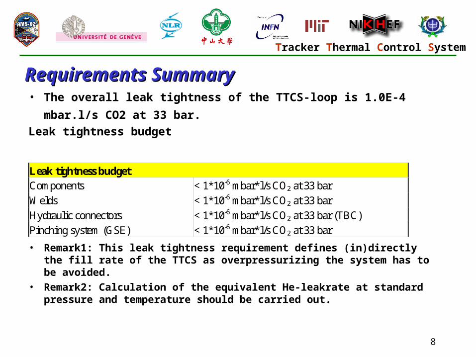
• The overall leak tightness of the TTCS-loop is 1.0E-4 mbar.l/s CO2
at 33 bar.
Leak tightness budget
• Remark1: This leak tightness requirement defines (in)directly the fill rate of the TTCS as overpressurizing the system has to be avoided.
• Remark2: Calculation of the equivalent He-leakrate at standard pressure and temperature should be carried out.
Requirements SummaryRequirements Summary
Leak tightness budget Components < 1*10-6 mbar*l/s CO2 at 33 bar
Welds < 1*10-6 mbar*l/s CO2 at 33 bar
Hydraulic connectors < 1*10-6 mbar*l/s CO2 at 33 bar (TBC)
Pinching system (GSE) < 1*10-6 mbar*l/s CO2 at 33 bar
9
Tracker Thermal Control System
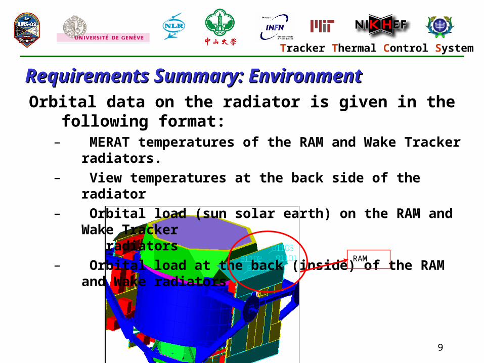
Orbital data on the radiator is given in the following format: – MERAT temperatures of the RAM and Wake Tracker radiators.
– View temperatures at the back side of the radiator
– Orbital load (sun solar earth) on the RAM and Wake Tracker radiators
– Orbital load at the back (inside) of the RAM and Wake radiators
Requirements Summary: EnvironmentRequirements Summary: Environment
RAM

10
Tracker Thermal Control System
Requirements Summary: EnvironmentRequirements Summary: EnvironmentI/F DATA BETA_0-15-20-15_hot
-225,0
-175,0
-125,0
-75,0
-25,0
25,0
75,0
125,0
0 2 4 6 8 10 12 14
Orbital Position (1-13)
Tem
per
atu
re [
C]
-400,0
-300,0
-200,0
-100,0
0,0
100,0
200,0
RAM Merat 81100
RAM Merat 81101
RAM Merat 81102
RAM Merat 81103
WAKE Merat 82100
WAKE Merat 82101
WAKE Merat 82102
WAKE Merat 82103
Tinside 381100
Tinside 381101
Tinside 381102
Tinside 381103
Tinside 382100
Tinside 382101
Tinside 382102
Tinside 382103
RAM Load 81100
RAM Load 81101
RAM Load 81102
RAM Load 81103
WAKE Load 82100
WAKE Load 82101
WAKE Load 82102
WAKE Load 82103
Inside Load 381100
Inside Load 381101
Inside Load 381102
Inside Load 381103
Inside Load 382100
Inside Load 382101
Inside Load 382102
Orbital Data TTCS Radiators Incl. Orbital load
Orbital load (solar + albedo + earth)
Radiator back side mean I/F temperatures
WAKE Merat temperatures
RAM Merat temperatures

11
Tracker Thermal Control System
Typical Operational Radiator Temperatures Typical Operational Radiator Temperatures (BBM)(BBM)
Datafile name: d:\CO2-loop data\030527 CO2 0906.asc
-40
-35
-30
-25
-20
-15
-10
-5
0
5
15500 17500 19500 21500 23500 25500
time[s]
AccuTop
LiqHX_in
LiqTopHX_out
LiqLowHX_out
RAM-out
WAKE-out
To7
To12
To16
To22
To30
Ti1
Ti12
Ti18
Ti21
Ti23
Ti24
HX-vap-out
Tracker thermal I/F temperatures (evaporators)Accu
wake out
ram out
HX in
RAM and WAKE heat sinks are forced to thermal model radiator temperature profile
HX out
Tem
pera
ture
[C
]
Time [s]

12
Tracker Thermal Control System

13
Tracker Thermal Control System

14
Tracker Thermal Control System
TTCS Functionality TTCS Functionality Component Function Pump Transport the fluid through the loop Accumulator Regulate the evaporator temperature in the tracker
Account for the expansion of the working fluid Accumulator Peltier elements Regulate evaporation set-point in all operation modes (cooling) Accumulator heaters Regulate evaporation set-point in all operation modes (heating)
Emergency accumulator heat-up in case liquid line temperature approaches saturation temperature (to avoid cavitation in pump)
Valves (liquid line) Control the mass flow distribution between Wake and RAM radiator
Heat Exchanger Exchange heat between hot evaporator outlet and cold evaporator inlet. Reduction of pre-heater power
Evaporator Collect heat at the tracker electronics. The evaporation process provides the temperature stability required.

15
Tracker Thermal Control System
TTCS Functionality TTCS Functionality
Condensers Remove the heat from the working fluid to the radiators. The condensing process makes the heat transfer effective.
Absolute Pressure Sensors Monitor the absolute pressure inside the loop Differential Pressure Sensor Monitor pump pressure head LFM Monitor mass flow Pre-heaters Heat evaporator liquid inlet to saturation point Start-up heaters Additional heater for cold start-up (off during nominal
operation) Dallas Temperature Sensors Monitor temperatures TTCS temperatures Pt1000 Temperature Sensors Control pre-heater power
Control accumulator temperature Control liquid line valves (under discussion) Monitor cold temperatures on radiator and liquid lines

16
Tracker Thermal Control System
TTCS Operation TTCS Operation
AMSPayloadOps & Control
TTCSGroundOps &MonitoringSystem
TTCS-SS
CAN busses
Primary Loop (PL)
aequipment
bequipment
Secondary Loop (SL)
aequipment
bequipment
TTCE-A
aP aS
TTCE-B
bP bS
TMTC JMDC-CAN I/F
JMDC SW
TTCE Manager
Architectural overview

17
Tracker Thermal Control System
TTCS Operational modes TTCS Operational modes
M onito ring O pera ting M ode (M O M )
TTC E O n
TC
TC
S econdary loopO n
N orm alO pera tiona l
M ode
LoopS hut-downM ode
LoopS tart-up
M ode
TCTC
TC
TCauto(sfgrd)
auto(sfgrd)
TC
N orm alO pera tiona l
M ode
LoopS hut-downM ode
LoopS tart-up
M ode
P rim ary loopO n TCTC
TCauto(sfgrd)
auto(sfgrd)
TC
TC
M O M P rim ary Loop(M O M P L)
M O M S econdary Loop(M O M S L)

18
Tracker Thermal Control System
TTCS tube routing (schematic)TTCS tube routing (schematic)
WAKE
RAM
Primary TTCS
Secondary TTCSCircular tube routing using outer cylinder generic hole pattern
Condenser manifold Circular tube routing using former ACC/PMT mounting hole pattern
Two tube support beams
Condenser tubes supported by radiator diagonal strut
Evaporator lineCondenser line
Welded connectionsmade on site
Hydraulic connectors
Also at bottom evaporator branch not shown

19
Tracker Thermal Control System
Tube routingTube routing
Dimensions
• All tubing Do = 4 mm, Di=2.6 mm
• 1 Tracker return line (combined part) Do = 6 mm, Di=2.6
mm (only in box)
Additional integration issues
• Wire and start-up heaters are located at evaporator
tubes from box to Tracker
• All tubing wrapped in MLI or located below Flange MLI.
• Two support beams from top to bottom at wake side

20
Tracker Thermal Control System
Tube routing (support beams)Tube routing (support beams)

21
Tracker Thermal Control System
Condenser tube routingCondenser tube routing• Condenser design
– 14 capillary Inconel tubes (7 feed and 7 return lines) from each
manifold to the condensers (Di= 1mm, Do=2-3 mm
– Each capillary tube is wired with a wire heater to thaw the line
after AMS02 complete power down.
– Tubes are wrapped in MLI to minimise environmental heat leak.
– Each radiator is equipped with 2 x 3 redundant Pt1000’s for
switching.
– Each radiator is also equipped with heater cabling A & B for
health heaters.
– Electrical connectors located on a bracket boxes at main radiators
22
Tracker Thermal Control System
Condenser tubingCondenser tubingManifold positions
• Location at upper trunnion bridges T>-40 in all cases
– Condenser lines from manifold to box T > 40 C (no freezing)
– Parallel condenser lines are installed together with condenser
• Manifold design Y:\Projects\AMS-Tracker\Technical\Components\condensers\CondenserManifold25feb05.pdf
– brazed and welded design
– Manifold orientation should be convenient for tube routing.
– the manifold has a stainless steel tube end attached on the
box side
– tube end is orbital welded to the tube routed to the box right
after installation of the condenser

23
Tracker Thermal Control System
Condenser manifold locations Condenser manifold locations

24
Tracker Thermal Control System
Condenser Manifold location (detail)Condenser Manifold location (detail)
Upper trunnion bridge

25
Tracker Thermal Control System
Condenser tube routingCondenser tube routing• Electrical connectors (terminal blocks) are located on a
bracket boxes at main radiators
Picture CGS (Assenza)

26
Tracker Thermal Control System
Condenser Design & tube routingCondenser Design & tube routing
Tracker radiator Condenser inserts OHB Sept 2004

27
Tracker Thermal Control System
Condenser Design & tube routingCondenser Design & tube routing

28
Tracker Thermal Control System
Condenser Design & tube routing (MGSE)Condenser Design & tube routing (MGSE)
Rod I/F Bracket
Rod I/F Bracket
Rod I/F Bracket
Integration Bar 1 (temporary)In
tegr
atio
n B
ar 2
(te
mpo
rary
)
TTCS Condensator
Schematic OHB Sept 2004

29
Tracker Thermal Control System
TTCS BoxesTTCS Boxes
TTCS Box envelopes
Secondary & Starboard TTCSComponent Box
(TTCBS)
WAKERAM
TTCS Envelope location
X
Y
Z
Y
B. Verlaat (NIKHEF), 21 March 2003
Primary & Port TTCS Component Box
(TTCBP)
Starboard
Port

30
Tracker Thermal Control System
TTCS BoxesTTCS Boxes
TTCBP
Tracker radiator
Condenser
TTCE
TTPD
TTCBS

31
Tracker Thermal Control System
TTCS Box lay-outTTCS Box lay-out

32
Tracker Thermal Control System
TTCS Box lay-outTTCS Box lay-out

33
Tracker Thermal Control System
Components: PumpComponents: Pump

34
Tracker Thermal Control System
Components: PumpComponents: Pump• Initial Data Drop for PDR is performed
• Data only available for safety panel
(export license agreement)
• B-field test set-up is being manufactured
• BBM model impeller test starting in May
• Electronics design EM and QM will start next week

35
Tracker Thermal Control System
Components: Heat Exchanger Components: Heat Exchanger approx 68
approx 87 36 X18 x liquid18 x two-phase
=
weld
• two-phase to single phase plate type heat exchanger
• welded housing
• soldered stack of plates

36
Tracker Thermal Control System
Components: Heat Exchanger Components: Heat Exchanger
soldered stack of plates
• Soldering tests will be performed as soon as solder is delivered
bottom view
37
Tracker Thermal Control System
Components: Heat Exchanger Components: Heat Exchanger • Heat exchanger design is updated for box tubing
• Strength calculations show 4 mm wall thickness is
required
• Material is stainless steel
• The weld cannot be done by orbital welding (4 mm)
• EM prototype is planned end of April
– depends on a successful soldering test

38
Tracker Thermal Control System
Components: Oscillating Heat Pipe Components: Oscillating Heat Pipe
• Working Fluid FC-87 (inert, non-toxic)
• Volume tubing: 2.3 ml
• Fill rate 70% (i.e. 1.6 ml FC-87)
• Heat supply by Minco foil heater Minco foil K5229 type 1 see specs below
• Cooling by two-phase line
• Operation only in cold orbits at set-points below 5 C Default disabled
• Construction needs to be ruggedized by a TBD frame
Heater modelBranch Voltage type Length (mm) Width (mm) Total length (mm) area (inch^2) area (cm^2)5229 28 Type 1 139.7 10.9 N/A 1.7 11.0
R (ohm) Current (A) Power Max. Power (W) [=V^2/R] Power density (W/cm^2)17.5 1.6 44.8 49.73 4.53

39
Tracker Thermal Control System
Safety Approach (thermal aspects)Safety Approach (thermal aspects)• Safety requirement box -40 C <T < 65 C
– hot case solved thermostats on power line (see lay-out)
– cold case solved by USS worst case cold temperature and
safety heaters as back-up
(to avoid freezing and for electronics survival)
• Safety requirement radiator -40 C <T < 80 C
– hot case shown by analysis (this afternoon)
– cold case solved by health heaters

40
Tracker Thermal Control System
Safety Approach (thermal aspects)Safety Approach (thermal aspects)• 9 parallel heater lines on PDS switch
(redundant 9A and 9B)
• 5 parallel lines on radiator
• 4 parallel lines on condensers
• Switch control by TTCE
– 6 Pt1000’s (3A and 3B)
• Switch performed by PDS
C om puterP t1000
condenser
P D S B U S AP D S
return
live TB
TB

41
Tracker Thermal Control System
Safety Approach (thermal aspects)Safety Approach (thermal aspects)• Condenser heater lay-out
340 mm
460 mm

42
Tracker Thermal Control System
Design Challenges/RisksDesign Challenges/RisksInterface temperature USS
– Start-up at + 10 C USS is extreme
– TEC coolers next to the pumps are foreseen in
case margin is small
Accumulator (design performed by CAST)
– During launch temperatures above T(critical) can easily occur
– Concern about bubbles in accumulator
– CAST is investigating this issue by test
Freezing
– Freezing test to “measure” MDP
– More in separate presentation

43
Tracker Thermal Control System
Integration aspects Integration aspects (welding/hydraulic connectors)(welding/hydraulic connectors)
Hydraulic connectors
– Type: Dynatube fitting, Resistoflex Aerospace
– Stainless Steel 15-5PH H1075 (-81 C to 343 C)
– No leaks (MIL-F-85720) upto 8000 psi
– Technical reply supplier (expected any moment)
Micro-welding
– Swagelock offers a “new” micro-welding technique
– A meeting between AMS02 integration specialists and
swagelock weld specialists is proposed to investigate the
feasibility of this method

44
Tracker Thermal Control System
Electrical schematic and routingElectrical schematic and routing
PDS
thermostats
T T -C ra te
T T C E C o ld
T T C E H o t
JM D C
T T P DT T C S
P rim a ry L o o p
T T C SS e c o n d a ry L o o p
T ra c k e r
Secondory Cold Cables:1) Heater/peltier power2) Tem perature/Pressure3) Valve/Pum p power4) Valve/Pum p feedback
Secondary Hot Cables:1) Heater/peltier power2) Tem perature/Pressure3) Valve/Pum p power4) Valve/Pum p feedback
Prim ary Cold Cables:1) Heater/peltier power2) Tem perature/Pressure3) Valve/Pum p power4) Valve/Pum p feedback
Prim ary Hot Cables:1) Heater/peltier power2) Tem perature/Pressure3) Valve/Pum p power4) Valve/Pum p feedback
Prim ary Cold Cables:1) Heater power2) Tem perature
Prim ary Hot Cables:1) Heater power2) Tem perature
Secondary Cold Cables:1) Heater power2) Tem perature
Secodary Hot Cables:1) Heater power2) Tem perature
Power Hot Cables:1) Power2) Power control
Power Cold Cables:1) Power2) Power control
Com m unication Hot Cables:1) CAN
Com m unication Cold Cables:1) CAN