traceroute resolver user guide v1.2 - packetiq.com traceroute resolver user guide v1.2...3 reporting...
TRANSCRIPT
TraceRoute Resolver
User Guide
V1.2.8
© Copyright 2005-2012 PacketIQ Inc.
www.packetiq.com

2
NOTICE
PacketIQ Inc. provides this software program and this publication “as is” without warranty of any kind, either expressed or implied, including, but not limited to, the implied warranties of merchantability or fitness for any particular purpose. PacketIQ Inc. does not guarantee and is not responsible for the functionality, accuracy, or usefulness of this program beyond the features and intended purposes documented in this User Guide. PacketIQ Inc. will not be liable (i) to any person or company or entity for any incidental, consequential, or indirect damages (including damages for loss of business profits, business interruption, loss of business information, and the like) arising out the use of or inability to use this product even if PacketIQ Inc. or any authorized PacketIQ Inc. representative has been advised of the possibility of such damages, or (ii) for any claim by any other party.
Further, PacketIQ Inc. reserves the right to make changes or improvements to the product described in this guide and to this publication without obligation of PacketIQ Inc. to notify any person of such revision or changes, even if such changes reduce or eliminate a previous capability of the product.
Copyright
© Copyright 2005-2012 PacketIQ Inc. All rights reserved. No part of this publication may be reproduced, translated, or distributed without prior written permission of PacketIQ Inc.
Document Revision: 1.1 Product: PacketIQ TraceRoute Resolver Software Version: 1.2.8 Version Date: July 23, 2012
About PacketIQ
PacketIQ Inc. provides advanced network and application performance analysis, modeling, troubleshooting, and capacity management services. PacketIQ Inc. has developed a suite of innovative applications to enable delivery of superior analysis services, and markets these applications to clients and consulting professionals.
Contacting PacketIQ
Sales & Info [email protected] www.packetiq.com
Technical Support [email protected]
3
Reporting Problems
PacketIQ provides email support of this application on a best-effort basis.
Problems should be reported to [email protected]. Please include the following:
Version number and date of the product
Environment the application is working in (Windows version – CPU – Memory)
Full description of the problem, including screenshots if applicable
If possible, copies or partial copies of the network information file and/or traceroute results with which the problem can be duplicated.
Suggesting Improvements
Suggestions for adding additional features or functionality to this product can be sent to [email protected] for possible inclusion in the next version.
Trademarks
All trademarks, trade names, service marks and logos referenced or displayed herein belong to their respective companies.
Microsoft and Windows and Excel and SQL Server are registered trademarks or trademarks of Microsoft Corporation in the United States and/or other countries.
MySQL is a trademark of MySQL AB.
NetQoS and NetVoyant are registered trademarks or trademarks of NetQoS, Inc.
SolarWinds and Orion are registered trademarks of SolarWinds in the United States and/or other countries.
RazorSQL is a product of Richardson Software, LLC.
PacketIQ and the PacketIQ logo are trademarks of PacketIQ Inc.
Notice Regarding Examples of Accessing and Exporting Data from Network Management Systems/Solutions
The examples of accessing and utilizing the products and services offered by the various network management systems/solutions referenced herein, as well as examples of the formats of exported data, are offered to aid the user of this product in understanding how to successfully export network information data from these systems/solutions and use the exported data with this product. These examples are in no way meant to endorse, disparage, or compare any of these products. Furthermore, these examples are in no way meant to replace, supplement, or contradict any official instructions or user guides or manuals provided by the respective product/service provider. The user is wholly responsible for obtaining and referencing the appropriate training and/or documentation regarding use of any network management system/solution, and for the proper operation of these systems.
Note: A Read-Only login is strongly recommended for accessing any NMS database to avoid possible corruption of these databases and/or systems, as is backing up your database prior to any work.
4
1 Table of Contents
Table of Figures .................................................................................................................... 6
2 Introduction .................................................................................................................... 7
2.1 Installing / Uninstalling the TraceRoute Resolver .................................................. 10
2.2 Using the TraceRoute Resolver ............................................................................ 10
2.2.1 More on Performing Searches ....................................................................... 12
2.2.2 Traceroute Results Data Formats .................................................................. 13
3 TraceRoute Resolver User Interface Controls .............................................................. 14
3.1 Menu and Traceroute Text Box Controls ............................................................... 14
3.1.1 Menu Options ................................................................................................ 14
3.1.2 TraceRoute Text Box Controls ....................................................................... 16
3.1.2.1 Show ((Same Subnets)) ............................................................................................ 17
3.1.2.2 Auto Clear On Paste ................................................................................................. 18
3.1.2.3 Auto-Process ............................................................................................................ 18
3.1.3 Network Information Results Section ............................................................. 18
3.1.4 Network Information Section Controls ............................................................ 19
3.1.4.1 Traceroute Format ................................................................................................... 19
3.1.4.2 Search String ............................................................................................................ 19
3.1.4.3 Search Wildcards ...................................................................................................... 20
3.1.4.4 Selected | All Columns ............................................................................................. 20
3.2 TraceRoute Resolver Settings .............................................................................. 21
3.2.1.1 TraceRouteResolver.prefs File ................................................................................. 21
3.2.1.2 Current Network Info File ........................................................................................ 22
3.2.1.3 Save Traceroute Filename Prefix ............................................................................. 22
3.2.1.4 Select Columns to Display ........................................................................................ 22
3.2.1.5 Select Columns to Include in Searches .................................................................... 23
3.2.1.6 Default Settings ........................................................................................................ 23
3.2.1.7 Show ((Same Subnets)) ............................................................................................ 24
3.2.1.8 Auto Clear On Paste ................................................................................................. 24
3.2.1.9 Auto-Process ............................................................................................................ 24
3.2.1.10 Display Command Line ......................................................................................... 24
3.2.1.11 Command Line Display Column ........................................................................... 25

5
3.2.1.12 Default Traceroute Format ................................................................................... 25
3.2.2 Network Information File Error Messages ......................................................25
4 Preparing Network Data for the TRR ............................................................................26
4.1 TRR Network Information File Format ...................................................................26
4.1.1 Saving Network Information from an Excel File to a .CSV File .......................28
4.1.2 Testing a Network Information File with TraceRoute Resolver .......................28
4.2 Obtaining Network Info Data from a NMS Database .............................................29
4.3 Tools for Working with a SQL Database ................................................................29
4.4 Extracting Data from a NetQoS® NetVoyant® Database ......................................30

6
Table of Figures
Figure 1: Example Traceroute from a Cisco Router .............................................................. 8
Figure 2: Cisco Traceroute Results Enhanced by the TraceRoute Resolver ......................... 9
Figure 3: Resolving Same Subnets Illustration ...................................................................... 9
Figure 4: Performing a Search with a Partial String ............................................................. 10
Figure 5: Processed Traceroute Results ............................................................................. 11
Figure 6: Performing a Search with a Partial String ............................................................. 12
Figure 7: Using Wildcards in Search Strings ....................................................................... 12
Figure 8: Performing a Search with an IP Address .............................................................. 12
Figure 9: File - Save Traceroute/Search Info Filename Examples ....................................... 15
Figure 10: About PacketIQ TraceRoute Resolver Form ...................................................... 15
Figure 11: User Controls in the TraceRoute Box Section .................................................... 16
Figure 12: Show Same Subnets Results Example .............................................................. 17
Figure 13: Same Subnets Example Diagram ...................................................................... 17
Figure 14: Search Results with a Partial Search String ....................................................... 19
Figure 15: Search Wildcards Example ................................................................................ 20
Figure 16: TraceRoute Resolving Settings Form ................................................................. 21
Figure 17: TraceRouteResolver.prefs File Contents ............................................................ 22
Figure 18: Search Column Not Displayed Error Message ................................................... 23
Figure 19: Command Line Displayed with Network Information Results .............................. 24
Figure 20: File Not Found Error Message ........................................................................... 25
Figure 21: No Network Info Data Error Message ................................................................. 25
Figure 22: Example of a Network Information file viewed in Excel ....................................... 27
Figure 23: RazorSQL Startup Screen .................................................................................. 30
Figure 24: RazorSQL Connection Profile - Database Type Selection .................................. 31
Figure 25: RazorSQL Connection Settings .......................................................................... 31
Figure 26: RazorSQL Export Query Results Icon ................................................................ 33
Figure 27: RazorSQL Export Type Selection ....................................................................... 33
Figure 28: RazorSQL Export Options .................................................................................. 34
Figure 29: RazorSQL - Export Filename Selection .............................................................. 34
7
2 Introduction
The PacketIQ TraceRoute Resolver (TRR) is a Windows® application designed to enhance network traceroute results with additional information on Enterprise routing devices including interfaces, link speeds, subnet masks, etc.
The TRR matches traceroute IP addresses for each hop with records from a Network Information file which has been pre-prepared from available sources of data such as a network management system and/or manual compilation.
This information is essential for:
Troubleshooting network or application performance problems
Conducting network impact and performance assessments
Day to day administration of network devices and LAN/WAN links
The TRR Search feature also makes it possible to easily find any of the Network Information from string search results.
TRR results can be saved to a text file in Tab-delimited format or Copy/Pasted into applications such as Microsoft® Excel®.
Why do I need the TraceRoute Resolver?
When troubleshooting a networked application performance issue, or conducting a network impact and performance assessment prior to implementing new applications, it is essential to accurately identify the network paths between the user locations and the application server(s) so that bandwidth allocations and usage levels can be measured on all of the WAN links in each path and to measure network path latency, as these can be significant factors in networked application performance. A traceroute can also uncover a routing problem that wouldn't have been revealed otherwise – so performing a traceroute to definitively identify the network path devices and links should be one of the first steps in most analysis and troubleshooting activities. If your network is fairly small you might know the configuration off the top of your head, but if your network is regional, national, or global in size you can’t reasonably know all of the pertinent devices and link details - so you’ll probably go looking for a network diagram. The problem with network diagrams is that they can be oversimplified and leave out important details and/or they may be dated and inaccurate – if they exist at all. The only way to accurately and positively identify all of the WAN links in a network path is to perform a traceroute between the end-user location(s) and the application server(s), resolve the traceroute information into network devices and interfaces, and identify any in-path WAN links connected to those interfaces. A traceroute is a computer network utility that displays the IP address of the interface on each router (or switch that performs routing functions) that a network packet enters along the path between the station executing the traceroute and a target host/device. If that router’s interface IP address has been included in a Domain Name Server (DNS), the name of that device will be displayed as well, but many Enterprise organizations don’t record IP addresses for switch/router devices in DNS, so you may only get the IP address. The result
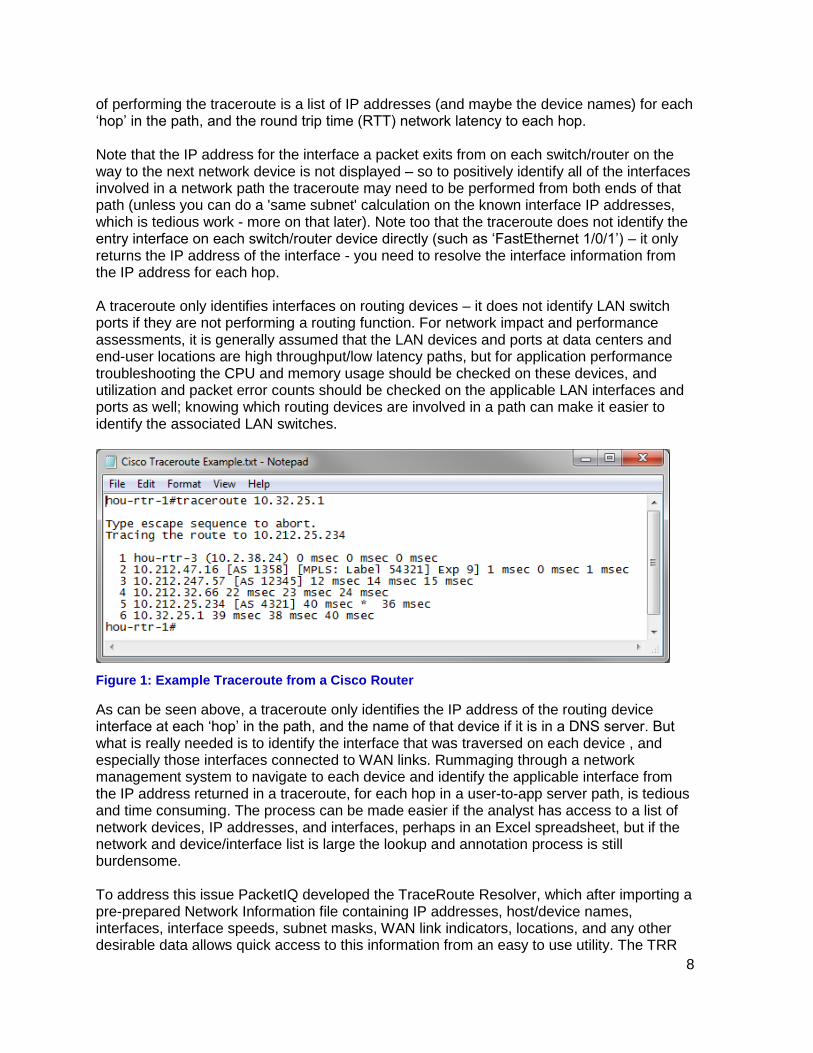
8
of performing the traceroute is a list of IP addresses (and maybe the device names) for each ‘hop’ in the path, and the round trip time (RTT) network latency to each hop. Note that the IP address for the interface a packet exits from on each switch/router on the way to the next network device is not displayed – so to positively identify all of the interfaces involved in a network path the traceroute may need to be performed from both ends of that path (unless you can do a 'same subnet' calculation on the known interface IP addresses, which is tedious work - more on that later). Note too that the traceroute does not identify the entry interface on each switch/router device directly (such as ‘FastEthernet 1/0/1’) – it only returns the IP address of the interface - you need to resolve the interface information from the IP address for each hop. A traceroute only identifies interfaces on routing devices – it does not identify LAN switch ports if they are not performing a routing function. For network impact and performance assessments, it is generally assumed that the LAN devices and ports at data centers and end-user locations are high throughput/low latency paths, but for application performance troubleshooting the CPU and memory usage should be checked on these devices, and utilization and packet error counts should be checked on the applicable LAN interfaces and ports as well; knowing which routing devices are involved in a path can make it easier to identify the associated LAN switches.
Figure 1: Example Traceroute from a Cisco Router
As can be seen above, a traceroute only identifies the IP address of the routing device interface at each ‘hop’ in the path, and the name of that device if it is in a DNS server. But what is really needed is to identify the interface that was traversed on each device , and especially those interfaces connected to WAN links. Rummaging through a network management system to navigate to each device and identify the applicable interface from the IP address returned in a traceroute, for each hop in a user-to-app server path, is tedious and time consuming. The process can be made easier if the analyst has access to a list of network devices, IP addresses, and interfaces, perhaps in an Excel spreadsheet, but if the network and device/interface list is large the lookup and annotation process is still burdensome. To address this issue PacketIQ developed the TraceRoute Resolver, which after importing a pre-prepared Network Information file containing IP addresses, host/device names, interfaces, interface speeds, subnet masks, WAN link indicators, locations, and any other desirable data allows quick access to this information from an easy to use utility. The TRR
9
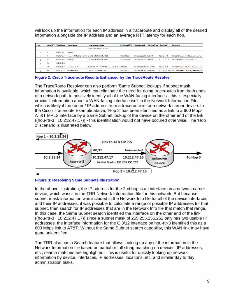
will look up the information for each IP address in a traceroute and display all of the desired information alongside the IP address and an average RTT latency for each hop.
Figure 2: Cisco Traceroute Results Enhanced by the TraceRoute Resolver
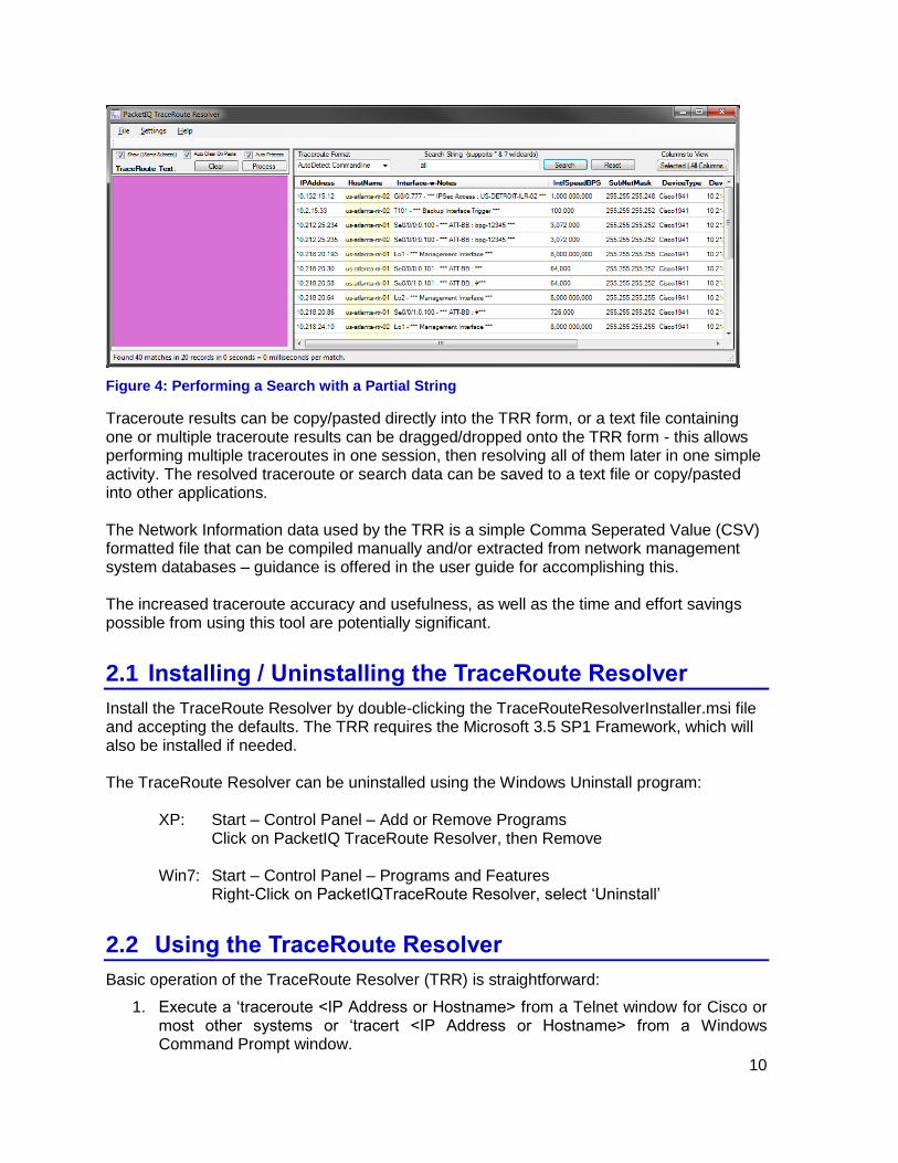
The TraceRoute Resolver can also perform ‘Same Subnet’ lookups if subnet mask information is available, which can eliminate the need for doing traceroutes from both ends of a network path to positively identify all of the WAN-facing interfaces - this is especially crucial if information about a WAN-facing interface isn't in the Network Information File, which is likely if the router / IP address from a traceroute is for a network carrier device. In the Cisco Traceroute Example above, 'Hop 2' has been identified as a link to a 600 Mbps AT&T MPLS interface by a Same Subnet lookup of the device on the other end of the link ((hou-rtr-3 | 10.212.47.17)) - this identification would not have occured otherwise. The 'Hop 2' scenario is illustrated below.
Figure 3: Resolving Same Subnets Illustration
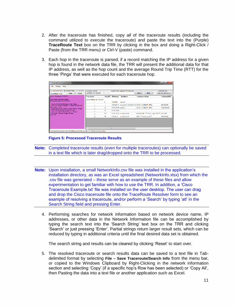
In the above illustration, the IP address for the 2nd hop is an interface on a network carrier device, which wasn't in the TRR Network Information file for this network. But because subnet mask information was included in the Network Info file for all of the device interfaces and their IP addresses, it was possible to calculate a range of possible IP addresses for that subnet, then search for IP addresses that are in the Network Info file that match that range. In this case, the Same Subnet search identified the interface on the other end of the link ((hou-rtr-3 | 10.212.47.17)) since a subnet mask of 255.255.255.252 only has two usable IP addresses; the interface information for the Gi3/12 interface on hou-rtr-3 identified this as a 600 Mbps link to AT&T. Without the Same Subnet search capability, this WAN link may have gone unidentified. The TRR also has a Search feature that allows looking up any of the information in the Network Information file based on partial or full string matching on devices, IP addresses, etc.; search matches are highlighted. This is useful for quickly looking up network information by device, interfaces, IP addresses, locations, etc. and similar day to day administration tasks.
10
Figure 4: Performing a Search with a Partial String
Traceroute results can be copy/pasted directly into the TRR form, or a text file containing one or multiple traceroute results can be dragged/dropped onto the TRR form - this allows performing multiple traceroutes in one session, then resolving all of them later in one simple activity. The resolved traceroute or search data can be saved to a text file or copy/pasted into other applications. The Network Information data used by the TRR is a simple Comma Seperated Value (CSV) formatted file that can be compiled manually and/or extracted from network management system databases – guidance is offered in the user guide for accomplishing this. The increased traceroute accuracy and usefulness, as well as the time and effort savings possible from using this tool are potentially significant.
2.1 Installing / Uninstalling the TraceRoute Resolver
Install the TraceRoute Resolver by double-clicking the TraceRouteResolverInstaller.msi file and accepting the defaults. The TRR requires the Microsoft 3.5 SP1 Framework, which will also be installed if needed. The TraceRoute Resolver can be uninstalled using the Windows Uninstall program: XP: Start – Control Panel – Add or Remove Programs Click on PacketIQ TraceRoute Resolver, then Remove Win7: Start – Control Panel – Programs and Features Right-Click on PacketIQTraceRoute Resolver, select ‘Uninstall’
2.2 Using the TraceRoute Resolver
Basic operation of the TraceRoute Resolver (TRR) is straightforward:
1. Execute a ‘traceroute <IP Address or Hostname> from a Telnet window for Cisco or most other systems or ‘tracert <IP Address or Hostname> from a Windows Command Prompt window.
11
2. After the traceroute has finished, copy all of the traceroute results (including the
command utilized to execute the traceroute) and paste the text into the (Purple) TraceRoute Text box on the TRR by clicking in the box and doing a Right-Click / Paste (from the TRR menu) or Ctrl-V (paste) command.
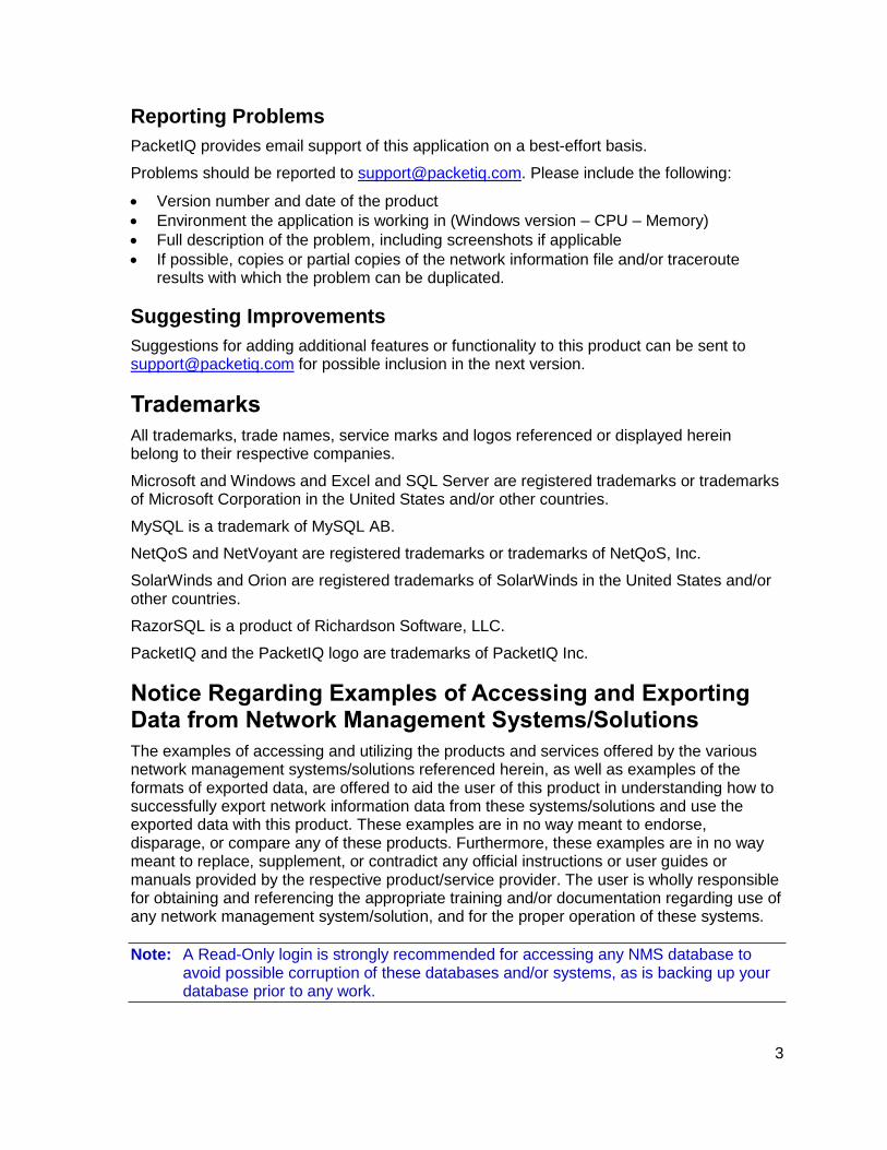
3. Each hop in the traceroute is parsed; if a record matching the IP address for a given hop is found in the network data file, the TRR will present the additional data for that IP address, as well as the hop count and the average Round Trip Time (RTT) for the three ‘Pings’ that were executed for each traceroute hop.
Figure 5: Processed Traceroute Results
Note: Completed traceroute results (even for multiple traceroutes) can optionally be saved in a text file which is later drag/dropped onto the TRR to be processed.
Note: Upon installation, a small NetworkInfo.csv file was installed in the application’s installation directory, as was an Excel spreadsheet (NetworkInfo.xlsx) from which the .csv file was generated – these serve as an example of these files and allow experimentation to get familiar with how to use the TRR. In addition, a ‘Cisco Traceroute Example.txt’ file was installed on the user desktop. The user can drag and drop the Cisco traceroute file onto the TraceRoute Resolver form to see an example of resolving a traceroute, and/or perform a ‘Search’ by typing ‘atl’ in the Search String field and pressing Enter.
4. Performing searches for network information based on network device name, IP addresses, or other data in the Network Information file can be accomplished by typing the search text into the ‘Search String’ text box on the TRR and clicking ‘Search’ or just pressing ‘Enter’. Partial strings return larger result sets, which can be reduced by typing in additional criteria until the final desired data set is obtained. The search string and results can be cleared by clicking ‘Reset’ to start over.
5. The resolved traceroute or search results data can be saved to a text file in Tab-delimited format by selecting File – Save Traceroute/Search Info from the menu bar, or copied to the Windows Clipboard by Right-Clicking in the network information section and selecting ‘Copy’ (if a specific hop’s Row has been selected) or ‘Copy All’, then Pasting the data into a text file or another application such as Excel.

12
2.2.1 More on Performing Searches
The TRR allows ad-hoc searches for network device names, IP addresses, or any other field in the network information file to be conducted by typing a string in the ‘Search String’ field in the TRR user interface, then clicking ‘Search’ or pressing ‘Enter’.
Cells containing search matches are highlighted in Light Yellow.
Figure 6: Performing a Search with a Partial String
Partial strings return larger result sets, which can be reduced by typing in additional search criteria and pressing Enter until the desired data set is obtained.
Search strings can include wildcards. An asterisk (*) matches any number of characters; a question mark (?) matches one character. In the example below, the *atlan* portion of the search string matches the ‘atlanta’ entries, and -?1 would match -01, -11, -21, etc.
Figure 7: Using Wildcards in Search Strings
A Search performed using IP addresses can also be useful.
Figure 8: Performing a Search with an IP Address
13
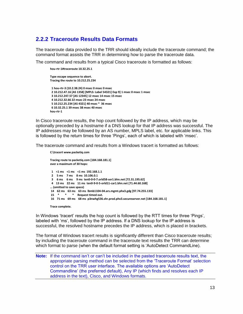
2.2.2 Traceroute Results Data Formats
The traceroute data provided to the TRR should ideally include the traceroute command; the command format assists the TRR in determining how to parse the traceroute data.
The command and results from a typical Cisco traceroute is formatted as follows:
hou-rtr-1#traceroute 10.32.25.1 Type escape sequence to abort. Tracing the route to 10.212.25.234 1 hou-rtr-3 (10.2.38.24) 0 msec 0 msec 0 msec 2 10.212.47.16 [AS 1358] [MPLS: Label 54321] Exp 9] 1 msec 0 msec 1 msec 3 10.212.247.57 [AS 12345] 12 msec 14 msec 15 msec 4 10.212.32.66 22 msec 23 msec 24 msec 5 10.212.25.234 [AS 4321] 40 msec * 36 msec 6 10.32.25.1 39 msec 38 msec 40 msec hou-rtr-1
In Cisco traceroute results, the hop count followed by the IP address, which may be optionally preceded by a hostname if a DNS lookup for that IP address was successful. The IP addresses may be followed by an AS number, MPLS label, etc. for applicable links. This is followed by the return times for three ‘Pings’, each of which is labeled with ‘msec’.
The traceroute command and results from a Windows tracert is formatted as follows:
C:\tracert www.packetiq.com Tracing route to packetiq.com [184.168.181.1] over a maximum of 30 hops: 1 <1 ms <1 ms <1 ms 192.168.1.1 2 5 ms 7 ms 8 ms 10.106.0.1 3 6 ms 6 ms 9 ms ten0-0-0-7.orld58-ser1.bhn.net [72.31.195.62] 4 13 ms 22 ms 11 ms ten0-9-0-5-orld11-car1.bhn.net [71.44.60.168] … (omitted to save space) 14 62 ms 63 ms 63 ms lbmb1104-04.ars.mgmt.phx3.gdg [97.74.255.133] 15 * * * Request timed out. 16 71 ms 69 ms 68 ms p3nwhg536.shr.prod.phx3.secureserver.net [184.168.181.1] Trace complete.
In Windows ‘tracert’ results the hop count is followed by the RTT times for three ‘Pings’, labeled with ‘ms’, followed by the IP address. If a DNS lookup for the IP address is successful, the resolved hostname precedes the IP address, which is placed in brackets.
The format of Windows tracert results is significantly different than Cisco traceroute results; by including the traceroute command in the traceroute text results the TRR can determine which format to parse (when the default format setting is ‘AutoDetect CommandLine).
Note: If the command isn’t or can’t be included in the pasted traceroute results text, the appropriate parsing method can be selected from the ‘Traceroute Format’ selection control on the TRR user interface. The available options are ‘AutoDetect Commandline’ (the preferred default), Any IP (which finds and resolves each IP address in the text), Cisco, and Windows formats.

14
3 TraceRoute Resolver User Interface Controls
3.1 Menu and Traceroute Text Box Controls
3.1.1 Menu Options
File – Open – Network Info File
This option allows selecting and importing a Network Information file.
Note: User options in the TraceRoute Resolver Settings form that will appear after selecting a Network Information file are discussed in TraceRoute Resolver Settings in Section 3.2.
Note: The TRR menu options can be activated from the keyboard using the ‘Alt’ key + an underlined letter method. For example, to select File – Open – Network Info File, the user could press Alt plus ‘F’, release the ‘Alt’ key, then press ‘O’, and then ‘N’. The keyboard press option letter is indicated for each menu option by the underlined letter for that option, as can be seen in the example above. The underlined letters will appear / disappear by pressing the ‘Alt’ key.
File – Open – Traceroute File
This option allows selection of a text file containing traceroute results data to be processed.
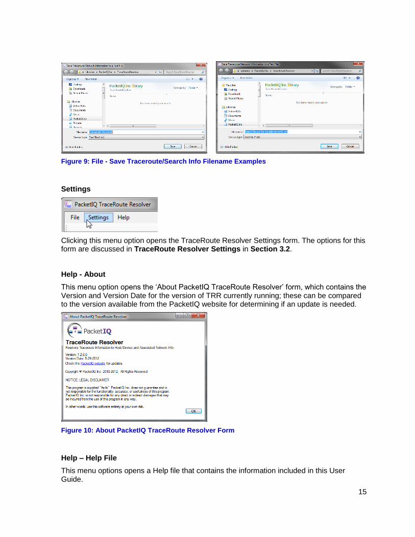
File – Save Traceroute/Search Info
This option opens a Windows Explorer window to save the network information resulting from resolving a traceroute or a search into a text file. Depending on which action was taken last, a recommended filename is offered which can be modified.
If the Save is activated after resolving traceroute results, the recommended filename is what was specified in TraceRoute Resolver Settings (in Section 3.2), with ‘.txt’ appended.
If the Save is activated after a search, the recommended filename is ‘Search Results for ‘<search string>’.txt
15
Figure 9: File - Save Traceroute/Search Info Filename Examples
Settings
Clicking this menu option opens the TraceRoute Resolver Settings form. The options for this form are discussed in TraceRoute Resolver Settings in Section 3.2.
Help - About
This menu option opens the ‘About PacketIQ TraceRoute Resolver’ form, which contains the Version and Version Date for the version of TRR currently running; these can be compared to the version available from the PacketIQ website for determining if an update is needed.
Figure 10: About PacketIQ TraceRoute Resolver Form
Help – Help File
This menu options opens a Help file that contains the information included in this User Guide.
16
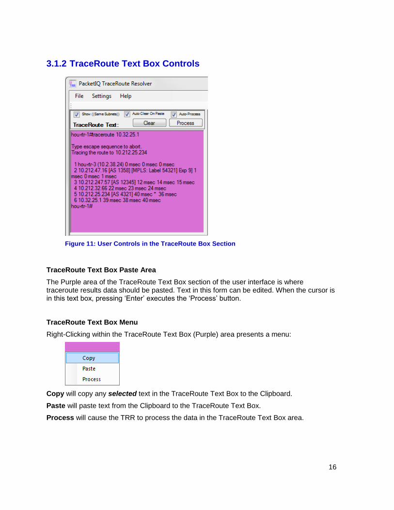
3.1.2 TraceRoute Text Box Controls
Figure 11: User Controls in the TraceRoute Box Section
TraceRoute Text Box Paste Area
The Purple area of the TraceRoute Text Box section of the user interface is where traceroute results data should be pasted. Text in this form can be edited. When the cursor is in this text box, pressing ‘Enter’ executes the ‘Process’ button.
TraceRoute Text Box Menu
Right-Clicking within the TraceRoute Text Box (Purple) area presents a menu:
Copy will copy any selected text in the TraceRoute Text Box to the Clipboard.
Paste will paste text from the Clipboard to the TraceRoute Text Box.
Process will cause the TRR to process the data in the TraceRoute Text Box area.

17
3.1.2.1 Show ((Same Subnets))
Show ((Same Subnets))
Figure 12: Show Same Subnets Results Example
Enabling this option (the default) tells the TRR to do a ‘same subnet’ look-up when a record cannot be found that matches an IP address in a traceroute hop. If one or more IP addresses are found that belong to the same network subnet, then device and interface information for the first device found is displayed. If more than one device/interface belonging to the same subnet is found, then the total number of matching entries is indicated within an additional set of parenthesis.
The fact that a same-subnet match is being displayed is indicated by displaying the IP address of the *substitute* device and interface surrounded with double parenthesis (( )). See the example highlighted in Hop 2 of Figure 12.
Why this is a very useful feature:
In the highlighted Hop 2 of Figure 12 above, IP address 10.212.47.16 belongs to an interface that is not in the Network Information file (in this example, because it belongs to a hypothetical AT&T MPLS cloud device). However, one of the nearest IP addresses that is in the information file is 10.212.47.17, which has a SubNetMask of 255.255.255.252; this mask means that there are only two valid IP addresses in this subnet – 10.212.27.16 and 10.212.27.17. The network information provided for the 10.212.27.17 address is the Gi3/12 interface of hou-rtr-3, which the Interface-w-Notes data indicates is a 600 Mbps uplink to an ATT MPLS cloud. So, instead of getting just an un-identified IP address for this hop, you get information for the interface on the other end of the link – which can often offer clues as to the nature of the link. This is especially reliable in the case of WAN links because they often utilize this same two-valid-addresses subnet masking scheme to preserve IP addresses.
A diagram depicting how a same-subnet match would occur based on the traceroute results depicted in Figure 12 is illustrated in Figure 13.
Figure 13: Same Subnets Example Diagram

18
Note: The Show ((Same Subnets)) option only functions if SubNetMask information in IP notation (xxx.xxx.xxx.xxx) format is provided in the Network Information file. See Preparing Network Data for the TRR in Section 4 for more information.
Note: Same-Subnets processing with a large number of traceroute hops and/or a very large Network Information file can take significantly longer to complete.
3.1.2.2 Auto Clear On Paste
Auto Clear On Paste
When this option is enabled, pasting new traceroute results data into the TraceRoute Text Box using the Right-Click / Paste menu will automatically clear any previous data and/or resolved network information results. Pasting using Ctrl-V will still append new text.
If this option is dis-abled, additional text can be pasted into the TraceRoute Text Box at the current insertion point (which can be changed by clicking within the form) using the menu.
3.1.2.3 Auto-Process
Auto-Process
When this option is enabled, pasting new traceroute results, or editing any of the text in the TraceRoute Text Box will automatically initiate Processing of the data in the form.
This option can be disabled if the traceroute results text is being significantly edited to avoid excessing processing delays.
3.1.3 Network Information Results Section
After resolving traceroute results data, the first two columns in the Network Information Results section will be the Hop Count followed by the Average RTT (Round Trip Time) derived from the average of the three ‘Ping’ results from the traceroute results.
Note: If a search has been conducted the Hop Count and Avg RTT fields will not appear.
The next two columns (or the first two columns in search results) will be the IP Address and the HostName for the identified device.
If the Network Information file is formatted per the recommendations in Preparing Network Data for the TRR in Section 4 the next column will be the ‘Interface’ for the device, and optionally an Interface description, interface speed, SubNetMask, device type, location, and any other information that would be useful.

19
3.1.4 Network Information Section Controls
3.1.4.1 Traceroute Format
Traceroute Format
The format of the traceroute results data to be processed in the TraceRoute Text Box can be indicated by selecting the appropriate entry from this control.
If the command line isn’t or can’t be included in the pasted traceroute results text (the TRR looks for ‘traceroute’ or ‘tracert’), the appropriate parsing method can be selected from the ‘Traceroute Format’ selection control.
The available options are:
AutoDetect Commandline (the preferred default) derives the appropriate parsing method from the traceroute command (if included in the traceroute results text)
Any IP locates and resolves any IP address in the text
Cisco assumes Cisco (or similar) formatted traceroute results
Windows assumes Windows formatted tracert results
3.1.4.2 Search String
Search String – Search - Reset
The TRR allows ad-hoc searches for network device names, IP addresses, or any other field in the network information file to be conducted by typing a string in the ‘Search String’ field in the TRR user interface. Partial strings return larger result sets, which can be reduced by typing in additional criteria until the final desired data set is obtained.
Figure 14: Search Results with a Partial Search String
A search is executed on the text in the ‘Search String’ text box by clicking ‘Search’ or just pressing ‘Enter’, which makes typing and testing increasingly specific searches faster/easier.
Clicking ‘Reset’ clears the Search String text box and all Network Information results.

20
3.1.4.3 Search Wildcards
Search strings can include wildcards. An asterisk (*) matches any number of characters; a question mark (?) matches one character.
In the example below, the *atlan* portion of the search string matches the ‘atlanta’ entries, and -?1 would match -01, -11, -21, etc.
Figure 15: Search Wildcards Example
3.1.4.4 Selected | All Columns
Selected | All Columns
Clicking the Selected | All Columns button toggles between displaying only the preferred Network Information results columns as configured in the TraceRoute Resolver Settings Form (discussed in TraceRoute Resolver Settings in Section 3.2), or displaying all of the columns of data provided in the Network Information file.
Initially this button is labeled ‘Selected | All Columns’; after being clicked the first time the button will sequentially toggle between ‘Selected Columns’ with no highlighting and ‘All Columns’ with Blue highlighting. After clicking this button the network information will be refreshed accordingly.
21
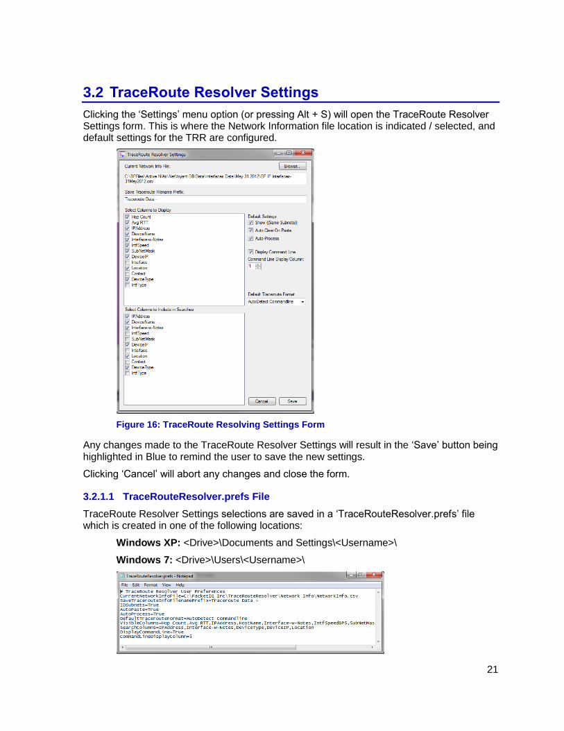
3.2 TraceRoute Resolver Settings
Clicking the ‘Settings’ menu option (or pressing Alt + S) will open the TraceRoute Resolver Settings form. This is where the Network Information file location is indicated / selected, and default settings for the TRR are configured.
Figure 16: TraceRoute Resolving Settings Form
Any changes made to the TraceRoute Resolver Settings will result in the ‘Save’ button being highlighted in Blue to remind the user to save the new settings.
Clicking ‘Cancel’ will abort any changes and close the form.
3.2.1.1 TraceRouteResolver.prefs File
TraceRoute Resolver Settings selections are saved in a ‘TraceRouteResolver.prefs’ file which is created in one of the following locations:
Windows XP: <Drive>\Documents and Settings\<Username>\
Windows 7: <Drive>\Users\<Username>\

22
Figure 17: TraceRouteResolver.prefs File Contents
Although this file can be edited, it is advisable to allow the TRR Settings form to make any changes to ensure reliable operation. If TRR controls operation becomes erratic, deleting this file and allowing it to be recreated afresh (by selecting a Network Information file and associated settings) may be helpful.
3.2.1.2 Current Network Info File
Current Network Info File
Clicking the ‘Browse’ button allows navigation and selection of the Network Information file to use with the TRR. The path of the current file is displayed in this section.
3.2.1.3 Save Traceroute Filename Prefix
Save Traceroute Filename Prefix
When the resolved results of a traceroute is being saved to a file (by selecting File – Save Traceroute/Search Info), the suggested filename prefix entered in this field will be displayed in the Windows Explorer filename field with ‘.txt’ appended to the end.
3.2.1.4 Select Columns to Display
Select Columns to Display
When a Network Information file is selected/imported, a list of all of the headers from the file that could be displayed as columns in the Network Information Section of the TRR is displayed in this section with checkboxes; these are all initially enabled by default. These
23
checkboxes can be un-checked to avoid having that column displayed in the normal view of resolved traceroute or search results.
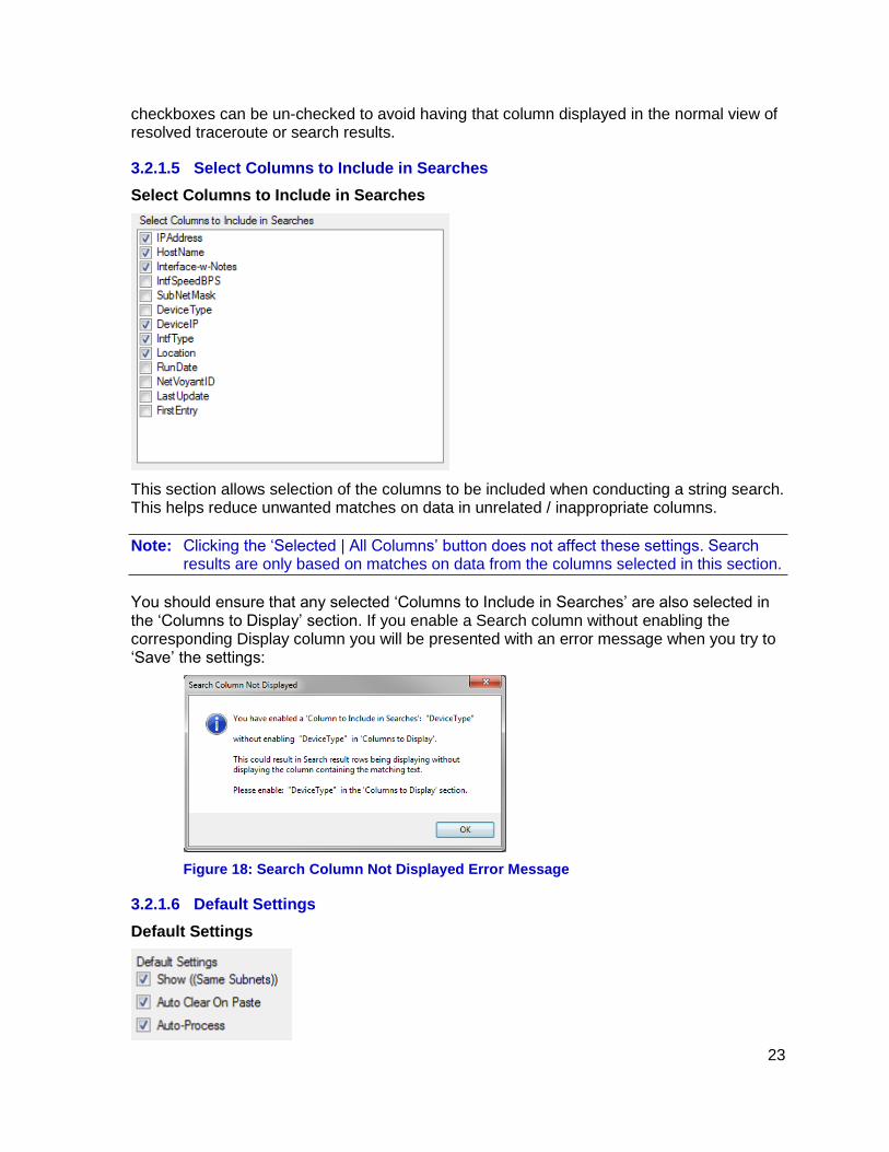
3.2.1.5 Select Columns to Include in Searches
Select Columns to Include in Searches
This section allows selection of the columns to be included when conducting a string search. This helps reduce unwanted matches on data in unrelated / inappropriate columns.
Note: Clicking the ‘Selected | All Columns’ button does not affect these settings. Search results are only based on matches on data from the columns selected in this section.
You should ensure that any selected ‘Columns to Include in Searches’ are also selected in the ‘Columns to Display’ section. If you enable a Search column without enabling the corresponding Display column you will be presented with an error message when you try to ‘Save’ the settings:
Figure 18: Search Column Not Displayed Error Message
3.2.1.6 Default Settings
Default Settings
24
These are the default settings (upon application launch) for the three controls that appear above the TraceRoute Text Box section of the TRR user interface.
3.2.1.7 Show ((Same Subnets))
Show ((Same Subnets))
Checking this option tells the TRR to do a ‘same subnet’ look-up when a record cannot be found that matches an IP address in a traceroute hop.
Also see the expanded explanation of this option in the Show ((Same Subnets)) description in Section 3.1.2.1.
3.2.1.8 Auto Clear On Paste
Auto Clear On Paste
When this option is enabled, pasting new traceroute result data into the TraceRoute Text Box will automatically clear any previous data and/or resolved network information results.
If this option is dis-abled, additional text can be pasted into the TraceRoute Text Box at the current insertion point (which can be changed by clicking on the desired insertion location).
3.2.1.9 Auto-Process
Auto-Process
When this option is enabled, pasting new traceroute results, or editing any of the text in the TraceRoute Text Box will automatically initiate Processing of the data in the form.
This option can be disabled if the traceroute results text is being significantly edited to avoid excessive processing delays.
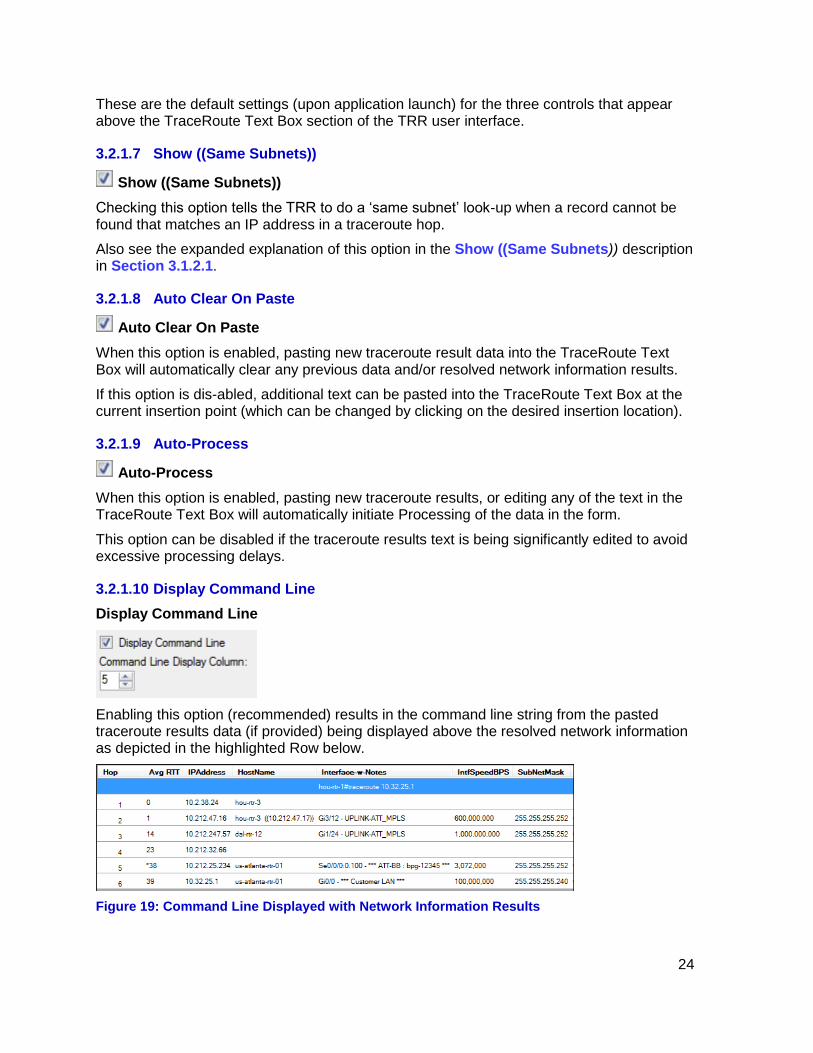
3.2.1.10 Display Command Line
Display Command Line
Enabling this option (recommended) results in the command line string from the pasted traceroute results data (if provided) being displayed above the resolved network information as depicted in the highlighted Row below.
Figure 19: Command Line Displayed with Network Information Results
25
3.2.1.11 Command Line Display Column
Command Line Display Column
This numerical selection controls which column (starting at ‘1’ on the left) the Command Line is displayed in (if enabled). This allows control of command line presentation only.
3.2.1.12 Default Traceroute Format
Default Traceroute Format
This control allows selection of the default setting (upon application launch) for the Traceroute Format control that appears above the Network Information section of the TRR user interface.
3.2.2 Network Information File Error Messages
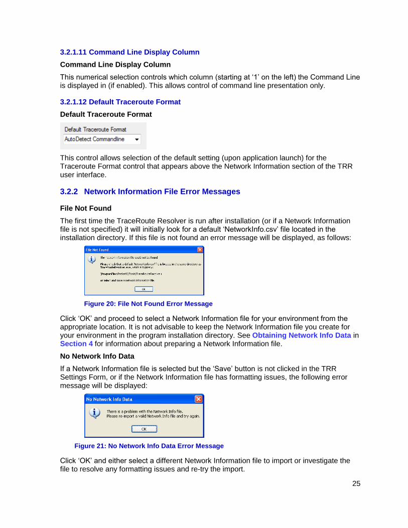
File Not Found
The first time the TraceRoute Resolver is run after installation (or if a Network Information file is not specified) it will initially look for a default ‘NetworkInfo.csv’ file located in the installation directory. If this file is not found an error message will be displayed, as follows:
Figure 20: File Not Found Error Message
Click ‘OK’ and proceed to select a Network Information file for your environment from the appropriate location. It is not advisable to keep the Network Information file you create for your environment in the program installation directory. See Obtaining Network Info Data in Section 4 for information about preparing a Network Information file.
No Network Info Data
If a Network Information file is selected but the ‘Save’ button is not clicked in the TRR Settings Form, or if the Network Information file has formatting issues, the following error message will be displayed:
Figure 21: No Network Info Data Error Message
Click ‘OK’ and either select a different Network Information file to import or investigate the file to resolve any formatting issues and re-try the import.
26
4 Preparing Network Data for the TRR
The TraceRoute Resolver utilizes network information imported from a Comma Separated Value (.csv) formatted file; this file has some specific formatting requirements but is otherwise fairly open to containing any information deemed useful.
The data for the Network Information file can be manually compiled using Excel and/or exported from a Network Management System database or other sources.
4.1 TRR Network Information File Format
The Network Information File utilized by the TraceRoute Resolver is a comma-separated value (.csv) formatted file containing information about your network.
Some of the columns (fields in each row) should follow a specific format and/or order in order to function well with the TRR; other / additional fields are non-specific and can contain anything useful to the user.
In the following description, each line in the .csv file is considered a ‘row’ of data; each comma separated entry in a given row is a field, which will be displayed by the TRR in ‘columns’ – this is the same as when viewing data in Excel (fields = cells).
The format requirements of the Network Information file are as follows:
1. Any line with a hash symbol (#) as the first character is considered a comment; the entire line is ignored.
2. The first (non-comment) line in the file should contain the column headers.
3. Column headers are not case sensitive; you can use upper and/or lowercase letters.
4. The first field must be an IP address, and the first six letters in the first column header must be ‘ipaddr’ (excluding the ‘ symbols). This is case insensitive.
5. The second field must be the hostname (or other preferred label).
6. It is recommended that the third field be the Interface.
7. If a subnet mask field is to be included in the data (which is required for the ‘Show Same Subnets’ function to operate), the header name must be ‘subnetmask’ (case insensitive) so that the TRR will know this data is available. The location of the subnetmask column (after the first three ipaddr – devicename – interface columns) doesn’t matter.
8. The data in the subnet mask field must follow IP address formatting: xxx.xxx.xxx.xxx
9. Header names can contain spaces, except for the first six letters of the (first) IP Address field, which must start with ‘ipaddr’, and the ‘subnetmask’ field.
10. Additional fields/columns can be added in any order, in any location.
27
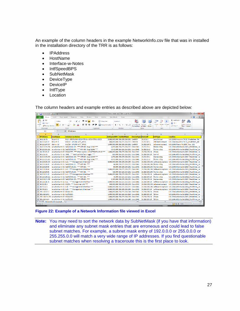
An example of the column headers in the example NetworkInfo.csv file that was in installed in the installation directory of the TRR is as follows:
IPAddress
HostName
Interface-w-Notes
IntfSpeedBPS
SubNetMask
DeviceType
DeviceIP
IntfType
Location
The column headers and example entries as described above are depicted below:
Figure 22: Example of a Network Information file viewed in Excel
Note: You may need to sort the network data by SubNetMask (if you have that information) and eliminate any subnet mask entries that are erroneous and could lead to false subnet matches. For example, a subnet mask entry of 192.0.0.0 or 255.0.0.0 or 255.255.0.0 will match a very wide range of IP addresses. If you find questionable subnet matches when resolving a traceroute this is the first place to look.

28
4.1.1 Saving Network Information from an Excel File to a .CSV File
Network information file data usually starts and/or is maintained in Excel and is exported to the required .csv format from there. A brief list of steps required to accomplish this include:
1. Be sure to ‘Save’ the Excel file before exporting the data. Save this .xlsx file with a date in the filename for version control purposes.
2. Do a File – Save As, select ‘CSV (Comma delimited) (.csv)’ from the ‘Save as type:’ drop-down box, and click ‘Save’.
3. Excel will then prompt you to make sure you want to save the data as a .csv:
Click ‘Yes’.
4. When you exit Excel, it will prompt you to save the changes to the .csv file (even if you didn’t change anything):
5. Click ‘Don’t Save’ or else Excel will prompt you to save the file again before it exits.
4.1.2 Testing a Network Information File with TraceRoute Resolver
6. On the TRR, click ‘Settings’ to open the Settings form.
7. Click ‘Browse’, navigate to and select the .csv file you just saved, and click ‘Open’. The TRR will attempt to import the data.
8. Check the status message at the bottom of the TRR – it should indicate ‘Successfully imported xxx Network Interface file entries.’
If the status message is ‘Imported xxx out of xxx entries. Check <Network Information file location> for duplicate IP Address entries.’, you may wish to check your data file to eliminate duplicate IP addresses. The TRR will continue to function, but will have only imported the first of the duplicate IP addresses in the file.
9. If the import was successful, choose the desired Display and Search columns and other options, then click ‘Save’ on the Settings form to save the settings.
29
4.2 Obtaining Network Info Data from a NMS Database
In this section an abbreviated example of extracting network device information from a popular Network Management System database is offered to aid in understanding the concepts and steps required for obtaining data from almost any database.
Most network management systems can do a ‘discovery’ of network devices based on a ‘seed’ IP address or a range of IP addresses; the NMS will send an ‘SNMP’ poll to each address (http://en.wikipedia.org/wiki/Simple_Network_Management_Protocol), and if the device responds, the NMS will perform a ‘MIB-2’ query (http://en.wikipedia.org/wiki/Management_information_base) that returns a variety of basic information on the device, and possibly additional SNMP queries to obtain vendor-specific information – all of this data is stored in the NMS database. The MIB-2 data represents much of the ‘extra’ information that might be desirable to include in the Network Information file for a network device, along with the interface, IP Address, and possibly the subnet mask.
Extracting data from a NMS database is not difficult, and if sufficient care is taken (Read-Only login, thoughtful construction of ‘Select’ statements, etc.) there is no reason not to take advantage of the wealth of information available from such sources.
Person unfamiliar with basic database principals are encouraged to read “MySQL Tutorial – a concise introduction to the fundamentals of working with MySQL” by Luke Welling and Laura Thomson. This book is published by MySQL Press; the ISBN is 0-672-32584-5 and is currently available from Amazon as a paperback and in Kindle format.
The MySQL Tutorial is a relatively quick-read paperback which, although written to guide the reader through the fundamentals of working with MySQL™ (thus the title sub-line), teaches the principals of database design, databases, tables, and indexes, as well as using ‘Select’ statements to extract data that are applicable to almost any database.
Note: Do not send requests to [email protected] asking for assistance with accessing and extracting data from your databases - PacketIQ cannot provide this level of support. If you experience problems accessing or extracting data from your database please contact your NMS vendor and/or database administrator - it may be helpful to provide these personnel with a copy of this document to help explain your goals.
4.3 Tools for Working with a SQL Database
Having a good database management / query tool is essential for browsing database tables and creating queries to extract network information data. One such tool is RazorSQL, which works with a wide range of database vendors (MySQL, MS SQL Server®, others); another is the Microsoft SQL Server® Management Studio, which only works with MS SQL Server.
The RazorSQL website is http://www.razorsql.com; the latest version of RazorSQL for Windows, Mac, or Linux platforms can be downloaded from the following URL:
http://www.razorsql.com/download.html
The example in this guide is based on use of the RazorSQL version 5.2.5 tool, but the concepts and capabilities are similar and can be applied to other tools and databases.

30
4.4 Extracting Data from a NetQoS® NetVoyant® Database
NetQoS® NetVoyant® is one of several popular network management products in use in Enterprise networks; NetVoyant uses a MySQL database to store device and sample data.
The following is a brief overview and example of the steps required to extract network information from a NetVoyant database (Version 6.1 in this example) using RazorSQL 5.2.5.
Note: It is strongly advised that you obtain and use a Read-Only login from your NMS administrator to avoid possible corruption of your databases and/or systems, and backing up the database prior to any work.
1. Start the RazorSQL application.
2. Upon the first launch of RazorSQL, you may be presented with a prompt to download the latest MySQL JDBC driver:
Click ‘Yes’, then ‘Continue’ on the next window.
3. The next window will announce ‘Driver Installation Complete. Hit OK to continue.’ Click ‘OK’. You will be presented with a fairly blank user interface with three panes. The Left pane is the database/table navigation area; the Top-Right pane is where SQL queries are generated (where you will write ‘select’ statements). The Bottom-Right pane is where the query results appear.
Figure 23: RazorSQL Startup Screen
31
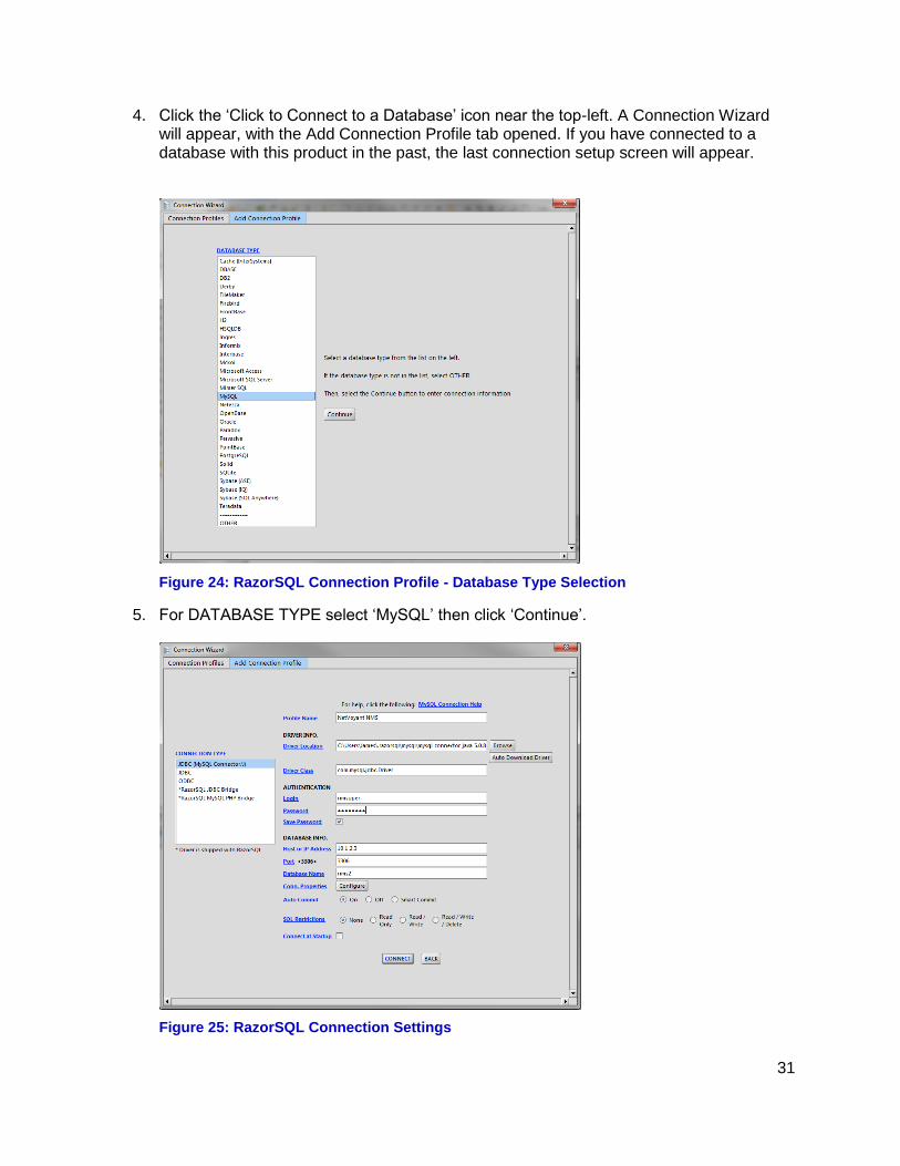
4. Click the ‘Click to Connect to a Database’ icon near the top-left. A Connection Wizard will appear, with the Add Connection Profile tab opened. If you have connected to a database with this product in the past, the last connection setup screen will appear.
Figure 24: RazorSQL Connection Profile - Database Type Selection
5. For DATABASE TYPE select ‘MySQL’ then click ‘Continue’.
Figure 25: RazorSQL Connection Settings

32
6. In the settings window that follows (above), provide or perform the following:
a. Profile Name: NetVoyant NMS (or similar title)
b. Login: (nmsuper in this example)
c. Password: (for the login id)
d. Host or IP Address: (of the primary NetVoyant NMS server)
e. Port: 3306 (default) (or appropriate port if the server manager or DBA has changed this)
7. Click ‘Connect’. If your selections are valid, you will see a short timer window then be
presented with a user interface showing a list of databases in the left navigation pane.
8. Click to expand ‘nms’ to view and browse a list of the database tables. The tables that commonly contain network device information have names such as ‘devices’ or ‘nodes’, ‘addresses’, ‘interfaces’, etc.
9. To generate a SQL query that pulls a collection of network device information from the NetVoyant database suitable for use with the TraceRoute Resolver, type (or copy/paste) the following into the Top-Right pane of RazorSQL:
use nms
select limit 100 addresses.addr_inet as IPAddress, devices.dev_alias as DeviceName, interfaces.ifdescr as Description, interfaces.ifspeed as InterfaceSpeed, addresses.addr_mask as SubNetMask, pollinst.pollinst_desc as Interface-w-Notes, devices.dev_name as DeviceIPAddr, devices.sys_location as Location, devices.sys_contact as Contact, device_models.model_name as DeviceType, interfacetypes.interfacetype as InterfaceType devices.device_id, interfaces.interface_id, from devices join interfaces on (devices.device_id = interfaces.device_id) left join pollinst on (interfaces.interface_id = pollinst.pollinst_id) left join device_models on (devices.model_id = device_models.model_id) left join interfacetypes on (interfaces.iftype = interfacetypes.ifid) left join addresses on (interfaces.interface_id = addresses.addr_if)
10. Press Ctrl-U (or click the Green Execute Query icon ) to execute the query.

33
11. The ‘select limit 100’ statement above limits the returned ‘rows’ to 100. After you have
confirmed that you are getting the expected data, delete the ‘limit 100’ after the ‘select’ statement and press Ctrl-U to re-execute a full query. For a network with ~80,000 interfaces a typical query time is ~250 seconds.
Note: Some databases (such as Microsoft SQL Server) require the user of a ‘Top 100’ command option instead of ‘Limit 100’ to limit query results. You should research the command query statement options in use with the database you are working with to ensure you utilize the proper formats.
12. After executing a full query (no ‘limit 100’ statement) you may need to run the scroll bar to the bottom of the displayed rows and then up & down to get all the rows to load.
13. Once all the rows are loaded (no further updates when moving the scroll bar), export the data to ‘Delimited File (COMMA)’ .csv file by clicking the ‘Export Query Results’ icon at the top of the Query Results pane:
Figure 26: RazorSQL Export Query Results Icon
14. In the Export Type window, select ‘Delimited File’ (the default).
Figure 27: RazorSQL Export Type Selection

34
15. In the Export Options window, select ‘<COMMA>’ as the Delimiter (the default) and accept the other defaults (<default> File Encoding, Convert Nulls to Blanks), then click ‘Next’.
Figure 28: RazorSQL Export Options
16. Select a location and filename for the exported data.
Figure 29: RazorSQL - Export Filename Selection
17. Import the .csv file using Excel 2010 or later (there may be too many rows for Excel
2003, which has a limit of ~64,000 rows). Right-click the .csv file (in Windows Explorer window), select ‘Open with’ and ‘Microsoft Excel’.
18. Insert a Row at the top of the data and label the columns with the appropriate headers. (IPAddress, DeviceName, Interface, …SubNetMask,… etc.).
19. Relocate the columns to the desired location, if desired (Click the column header, Right-Click, Cut, Right-Click a column header past the preferred location, Paste).
20. Sort the data by IP address (Click the Top-Left empty column header, (highlights all the data), Data, Sort, Sort by IPAddress, Sort On Values, Order A to Z, click ‘OK’).

35
21. It may be necessary to Right-Click the InterfaceSpeed column, Format Cells…, Number, Decimal places: 0, and check the ‘Use 1000 Separator(,), and click ‘OK’ to put the InterfaceSpeed column in bits-per-second format (vs 10E8 or similar notation).
22. Save the file in Excel format: File – Save As, Save as type: Excel Workbook (*.xlsx),
then click Save.
23. Then save the Excel file (with the format modifications) as a new .csv format file: File – Save As, Save as type: CSV (Comma delimited)(*.csv) with a different filename (to avoid over-writing the .csv file exported from RazorSQL, in case you need to start over).
The resultant .csv file can now be imported into the TraceRoute Resolver.
© Copyright 2005-2012 PacketIQ Inc.