trabajo fin de grado grado en ingeniería de tecnologías...
TRANSCRIPT

i
Equation Chapter 1 Section 1
Trabajo Fin de Grado
Grado en Ingeniería de Tecnologías Industriales
Communications between PLC and microcontroller
using Modbus Protocol
Autor: Eduardo Naranjo Piñar
Tutor: Luis Fernando Castaño Castaño
Dpto. Ingeniería de Sistemas y Automática
Escuela Técnica Superior de Ingeniería
Universidad de Sevilla
Sevilla, 2016

ii
Communications between PLC and microcontroller using Modbus Protocol
ii
iii
iii
Trabajo Fin de Grado
Grado de Ingeniería en Tecnologías Industriales
Communications between PLC and microcontroller
using Modbus Protocol
Autor:
Eduardo Naranjo Piñar
Tutor:
Luis Fernando Castaño Castaño
Doctor Ingeniero Industrial
Dpto. de Ingeniería de Sistemas y Automática
Escuela Técnica Superior de Ingeniería
Universidad de Sevilla
Sevilla, 2016

iv
Communications between PLC and microcontroller using Modbus Protocol
iv

v
v
Proyecto Fin de Carrera: Communications between PLC and microcontroller using Modbus Protocol
Autor: Eduardo Naranjo Piñar
Tutor: Luis Fernando Castaño Castaño
El tribunal nombrado para juzgar el Proyecto arriba indicado, compuesto por los siguientes miembros:
Presidente:
Vocales:
Secretario:
Acuerdan otorgarle la calificación de:
Sevilla, 2016
El Secretario del Tribunal

vi
Communications between PLC and microcontroller using Modbus Protocol
vi

vii
vii
Agradecimientos
A toda aquella persona, animal o cosa que me ha tenido que aguantar durante mis años de estudios

viii
Communications between PLC and microcontroller using Modbus Protocol
viii

ix
Abstract
The main goal of this document is developing multiple Modbus devices to communicate with
different computers and sensors. To explain this, the document will be divided in 3 chapters.
First of all, a small state of the art of the Modbus protocol will be done, explaining how it works
superficially, which are the most used functions, and how it handles the exceptions. Later there
will be an explanation on the development of the Modbus slave (serial and TCP/IP) with an
Arduino Mega board with the goal of sending a sensor output using a PC, and the development
of the Modbus master (serial) for reading data from a MASS-X solar sensor. Finally a Modbus
master which reads data from a solar panel (slave) and will send this data via Web Service in an
XML document has been documented.

x
Communications between PLC and microcontroller using Modbus Protocol
x
Introduction
xi
xi
Introduction
Whenever there are sensors in an industrial environment to have a better understatement about
what is happening, a way to send this data to a PLC or computer is necessary, which will read it
to make decisions about how the system has to respond. Because of this, the industry has
developed multiple communication protocols among all these devices, being Modbus the most
used nowadays.
Modbus is a serial protocol developed by Modicon (today Schneider Electric) for use it with
their PLCs. It is very simple and reliable thanks to its CRC, and it has become the standard de
facto protocol. It was written with industrial applications in mind, it is easy to maintain and to
use and royalty-free.
Even though PLCs are extremely reliable and robust computers, these are very expensive
compared to some new controllers such as Arduino from the Arduino Foundation and Raspberry
Pi from Element 14. Because of this, people are starting to use these computers to substitute
PLCs in some applications (like research or low-budget projects).
This is the main reason made this project was made, to make these devices compatible with the
protocol by using different libraries made by the user's community and to develop some user
interfaces to make the data visible for operators.
The first main goal is to program an Arduino Mega to read a sensor output and then send it to a
PLC or PC via Modbus. Thanks to this, the department will not need to buy expensive cards, and
will be able to connect the sensors far away from the PLC in case they are using Modbus
TCP/IP.
The second goal is to develop a Modbus master to read data from a system, which implements a
slave, and later will send this data through a Web Service in an XML format.
xii
Communications between PLC and microcontroller using Modbus Protocol
xii
Resumen en español
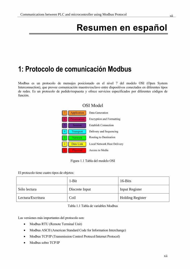
1: Protocolo de comunicación Modbus
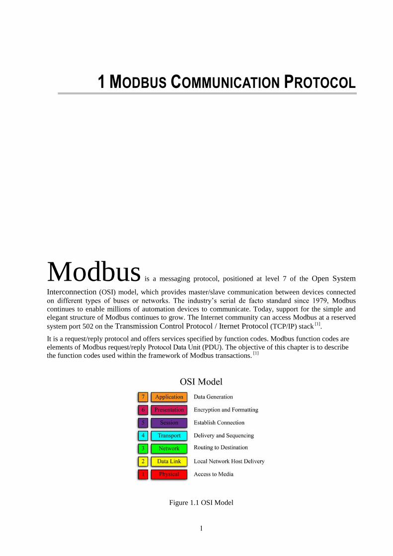
Modbus es un protocolo de mensajes posicionado en el nivel 7 del modelo OSI (Open System
Interconnection), que provee comunicación maestro/esclavo entre dispositivos conectados en diferentes tipos
de redes. Es un protocolo de pedido/respuesta y ofrece servicios especificados por diferentes códigos de
función.
Figura 1.1 Tabla del modelo OSI
El protocolo tiene cuatro tipos de objetos:
1-Bit 16-Bits
Sólo lectura Discrete Input Input Register
Lectura/Escritura Coil Holding Register
Tabla 1.1 Tabla de variables Modbus
Las versiones más importantes del protocolo son:
Modbus RTU (Remote Terminal Unit)
Modbus ASCII (American Standard Code for Information Interchange)
Modbus TCP/IP (Transmission Control Protocol/Internet Protocol)
Modbus sobre TCP/IP

Resumen en español
xiii
xiii
Cada dispositivo esclavo tiene asignado un único número de identificación. En Modbus serie sólo al maestro
se le permite iniciar una petición. Sobre Ethernet cualquier dispositivo puede hacerlo, sin embargo
normalmente es el maestro el que lo hace. La trama Modbus en su modalidad serie contiene el número de
esclavo con el que queremos comunicarnos y sólo el dispositivo con ese número responderá a la trama, incluso
aunque otros dispositivos también la reciban. Todas las tramas contienen información de redundancia para
detectar errores de transmisión.
La PDU (Protocol Data Unit) contiene toda la información necesaria para el esclavo y consta de los siguientes
elementos:
Código de función
Dirección del primer elemento
Número de elementos a leer o bytes de información
Los dispositivos se pueden dividir en dos tipos según la organización de los datos:
4 bloques diferentes (uno para cada tipo de objeto)
Figura 1.2 Dispositivo de 4 bloques
1 único bloque
Figura 1.3 Dispositivo de 4 bloques

xiv
Communications between PLC and microcontroller using Modbus Protocol
xiv
Los códigos de función más importantes son los siguientes:
01: Leer coils
02: Leer discrete inputs
03: Leer holding registers
04: Leer input registers
05: Escribir un sólo coil
06: Escribir un solo holding register
15: Escribir múltiples coils
16: Escribir múltiples holding registers
Cuando un maestro envía un pedido a un dispositivo esclavo, éste espera una respuesta normal. Uno de los
siguientes cuatro posibles eventos pueden ocurrir cuando el esclavo recibe la trama:
Si el esclavo recibe la trama sin errores de comunicación, y puede manejar la trama de manera
normal, devuelve una respuesta normal.
Si el esclavo no recibe la trama debido a un problema de comunicación, no se devuelve una respuesta.
El programa maestro eventualmente procesa una condición de timeout.
Si el esclavo recibe la trama, pero detecta un error de comunicación, no se devuelve una respuesta. El
programa maestro eventualmente procesa una condición de timeout.
Si el esclavo recibe un pedido sin error de comunicación, pero no puede manejar el pedido, éste
devuelve una respuesta de excepción informando al maestro de la naturaleza del error. El primer Byte
es el código de función sumando a 0x80, y el segundo es el código de excepción.

Resumen en español
xv
xv
2: Microcontrolador Mega 2560
El microcontrolador Arduino Mega 2560 es una placa basada el chip ATmega560. Tiene 54 pines digitales de
entrada/salida (de los cuales 15 pueden ser usados como salidas PWM (Pulse-Width Modulation)), 16 entradas
analógicas, 4 puertos serie, un cristal oscilador de 16MH, conexión USB, puerto de alimentación tipo jack, y
botón de reinicio, y es además compatibles con la mayoría de los complementos para el Arduino Uno.
Figura 2.1 Arduino Mega
El mega 2560 se puede programar con el software de Arduino, y viene preprogramado con un boot-loader que
te permite subir un nuevo programa sin necesidad de hardware de programación. Usa librerías de C, y la
sintaxis de programación es muy similar.
La placa se puede alimentar vía USB o mediante una fuente externa (AC/DC (Alternating Current / Direct
Current) o batería). La fuente de potencia es seleccionada de manera automática. Las fuentes externas se
conectan al puerto jack o al pin Vin. La placa necesita entre 6 a 20V para funcionar, pero no se recomienda
menos de 7 o más de 12. Puede además ofrecer fuentes de alimentación de 5V y 3.3V a otros dispositivos.
Cuenta con 256KB de memoria Flash para guardar los programas, 8KB de memoria SRAM (Static Random
Access Memory) y 4KB de EEPROM (Electrically Erasable Programmable Read-Only Memory) para guardar
datos que no se desea que sean volátiles.
El Arduino Mega dispones además de 4 puertos UART (Universal Asynchronous Receiver-Transmitter) para
TTL (Transistor-Transistor Logic). En caso de que fuera necesario, se conecta mediante RS232 o RS485 hay
que usar adapatadores especiales como el de la siguiente imagen (para RS485).
´
Figura 2.2 Conversor TTL/RS485
xvi
Communications between PLC and microcontroller using Modbus Protocol
xvi
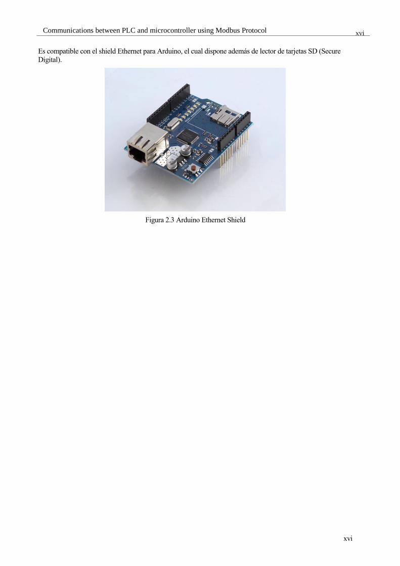
Es compatible con el shield Ethernet para Arduino, el cual dispone además de lector de tarjetas SD (Secure
Digital).
Figura 2.3 Arduino Ethernet Shield

Resumen en español
xvii
xvii
3: Dispositivos Modbus con Arduino
Se han desarrollado 3 programas diferentes para implementar el protocolo en el Arduino. 2 son por puerto
serie, uno maestro y otro esclavo y el tercero es un esclavo por TCP. Para programar se ha usado el software
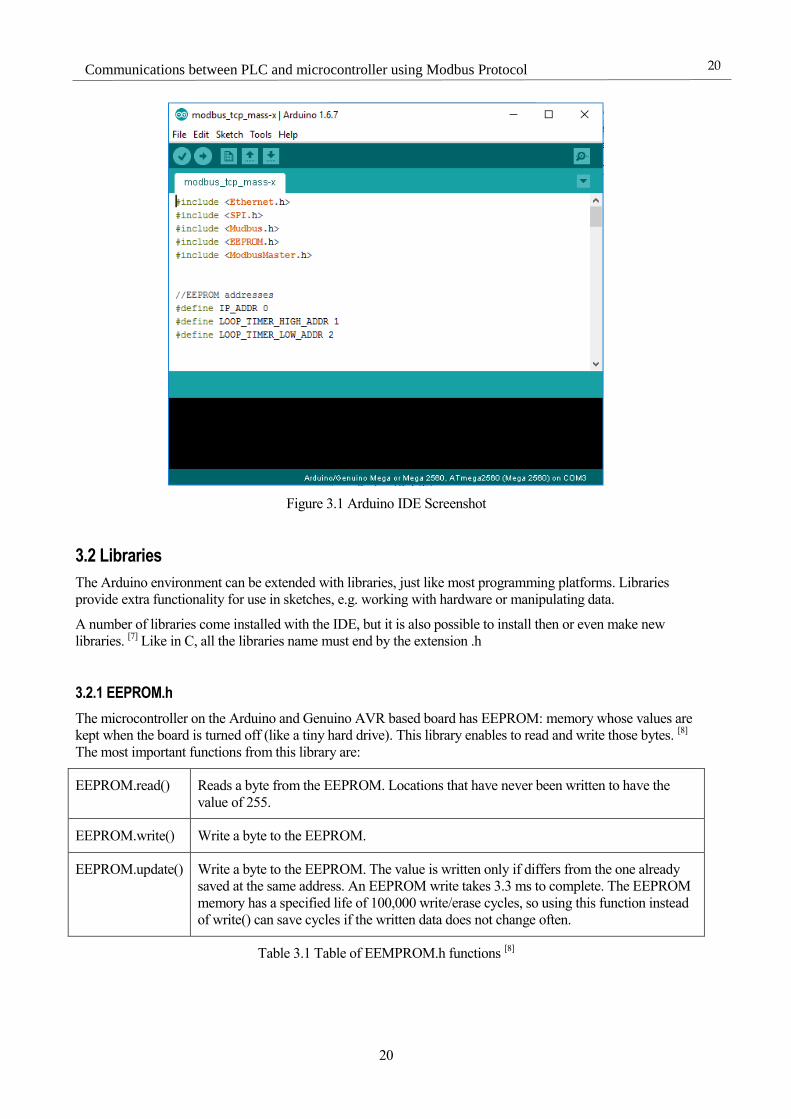
oficial de Arduino, el Arduino IDE (Integrated Development Environment).
Figura 3.1 Arduino IDE
3.1 Librerías
Las librerías que se han usado son las siguientes:
3.1.1 EEPROM.h
El microcontrolador tiene memoria EEPROM, cuyos valores se mantienen cuando la placa se apaga (como un
disco duro muy pequeño). Esta librería permite leer y escribir esos bytes y sus funciones más importantes son:
EEPROM.read() Lee un byte.
EEPROM.write() Escribe un byte.
EEPROM.update() Escribe un byte pero sólo si el valor difiere del ya guardado en la misma dirección. Una
escritura en la EEPROM lleva 3.3ms y la esperanza de vida es de 100.000 ciclos de
escritura/borrado, así que usar esta función en vez de write puede ayudar a mantener la
memoria por más tiempo.
Tabla 3.1 Métodos de EEPROM.h
xviii
Communications between PLC and microcontroller using Modbus Protocol
xviii
3.1.2 Average.h
Ésta es una colección de rutina para llevar a cabo análisis matemático de listas de números. Las funciones
usadas durante el proyecto son las siguientes:
Average.rolling() Añade un valor al historial desplazando a los valores anteriores en la lista
Average.mean() Calcula la media aritmética de la lista
Average.stddev Calcula la desviación estándar de la lista. Esta función es la única que no devuelve el
mismo tipo de datos que la lista, devolviendo siempre un float.
Average.maximum() Encuentra el valor más grande en la lista
Average.minimum() Encuentra el valor más pequeño en la lista
Tabla 3.2 Métodos de Average.h
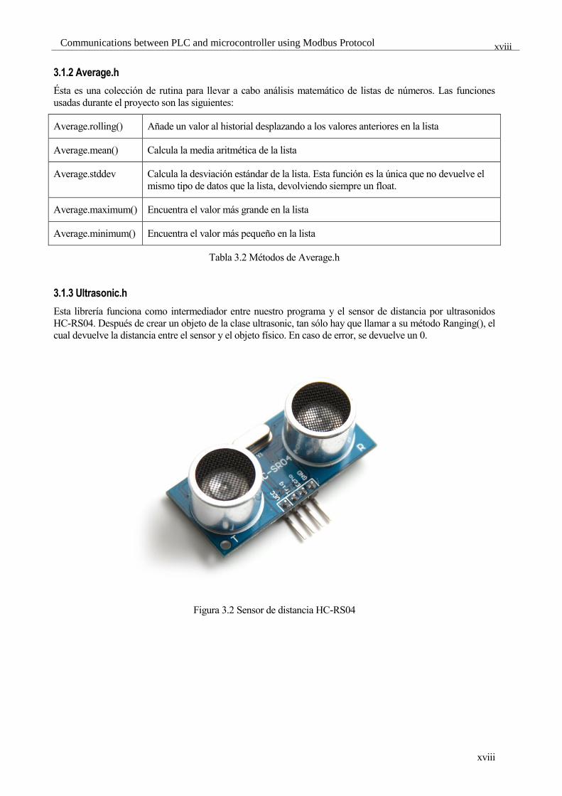
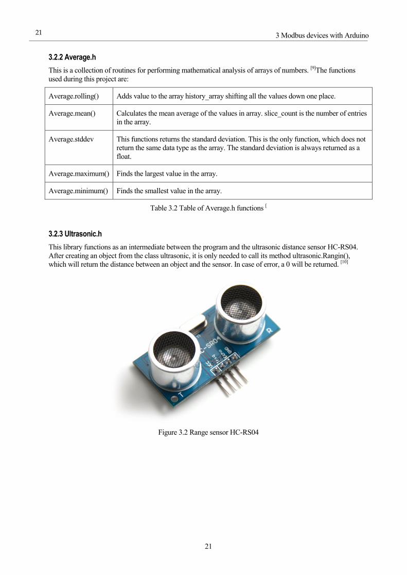
3.1.3 Ultrasonic.h
Esta librería funciona como intermediador entre nuestro programa y el sensor de distancia por ultrasonidos
HC-RS04. Después de crear un objeto de la clase ultrasonic, tan sólo hay que llamar a su método Ranging(), el
cual devuelve la distancia entre el sensor y el objeto físico. En caso de error, se devuelve un 0.
Figura 3.2 Sensor de distancia HC-RS04
Resumen en español
xix
xix
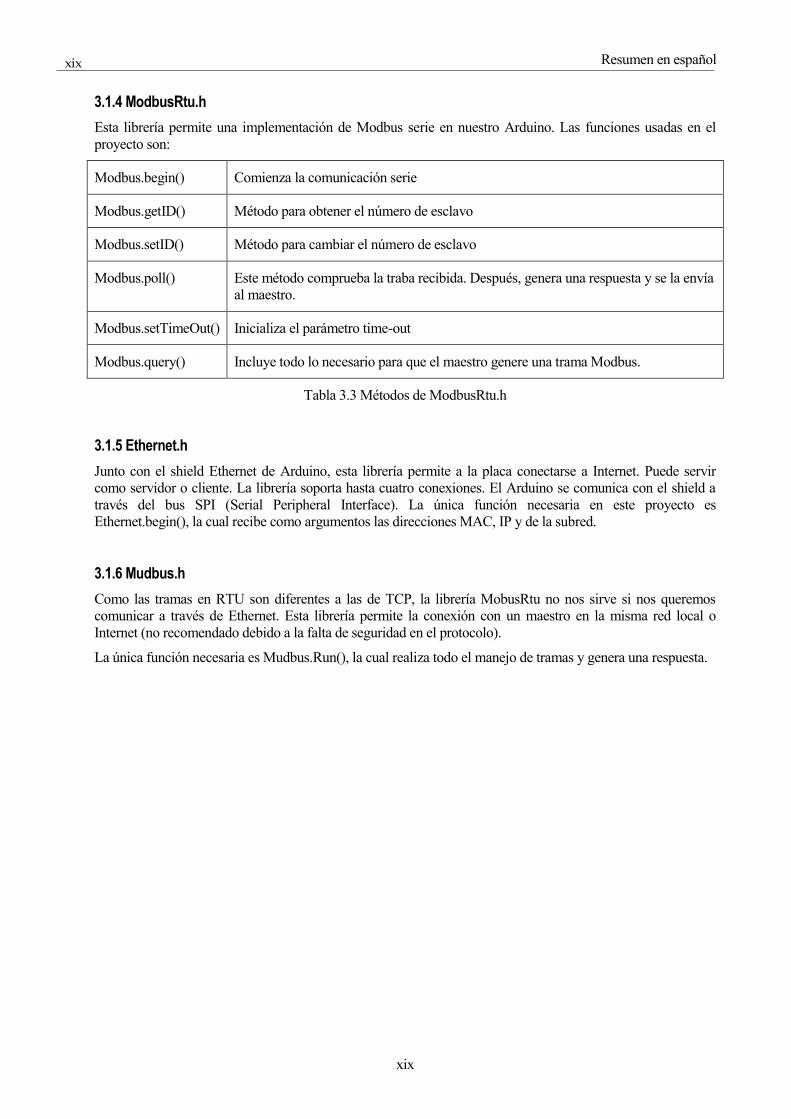
3.1.4 ModbusRtu.h
Esta librería permite una implementación de Modbus serie en nuestro Arduino. Las funciones usadas en el
proyecto son:
Modbus.begin() Comienza la comunicación serie
Modbus.getID() Método para obtener el número de esclavo
Modbus.setID() Método para cambiar el número de esclavo
Modbus.poll() Este método comprueba la traba recibida. Después, genera una respuesta y se la envía
al maestro.
Modbus.setTimeOut() Inicializa el parámetro time-out
Modbus.query() Incluye todo lo necesario para que el maestro genere una trama Modbus.
Tabla 3.3 Métodos de ModbusRtu.h
3.1.5 Ethernet.h
Junto con el shield Ethernet de Arduino, esta librería permite a la placa conectarse a Internet. Puede servir
como servidor o cliente. La librería soporta hasta cuatro conexiones. El Arduino se comunica con el shield a
través del bus SPI (Serial Peripheral Interface). La única función necesaria en este proyecto es
Ethernet.begin(), la cual recibe como argumentos las direcciones MAC, IP y de la subred.
3.1.6 Mudbus.h
Como las tramas en RTU son diferentes a las de TCP, la librería MobusRtu no nos sirve si nos queremos
comunicar a través de Ethernet. Esta librería permite la conexión con un maestro en la misma red local o
Internet (no recomendado debido a la falta de seguridad en el protocolo).
La única función necesaria es Mudbus.Run(), la cual realiza todo el manejo de tramas y genera una respuesta.

xx
Communications between PLC and microcontroller using Modbus Protocol
xx
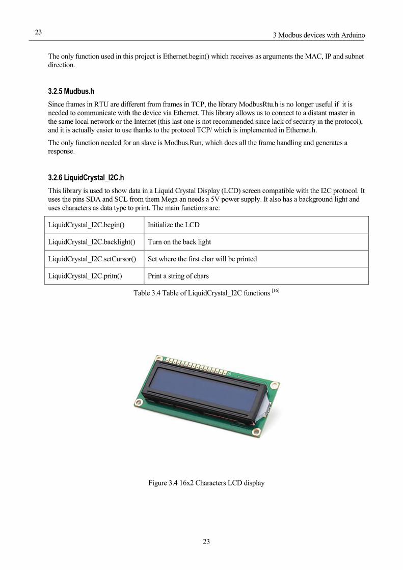
3.1.7 LiquidCrystal_I2C.h
Esta librería se usa para mostrar datos por una pantalla LCD de caracteres a través del protocolo I2C (Inter-
Integrated Circuit). Usa los pines SDA y SCL del Arduino y necesita una fuente de 5V. La pantalla es además
retroiluminable. Las funciones principales son:
LiquidCrystal_I2C.begin() Inicializa la pantalla
LiquidCrystal_I2C.backlight() Activa la retroiluminación
LiquidCrystal_I2C.setCursor() Selecciona en qué dirección se situará el cursor
LiquidCrystal_I2C.pritn() Muestra por pantalla una cadena de caracteres
Tabla 3.4 Médodos de LiquidCrystal_I2C.h
Figura 3.3 Pantalla LCD
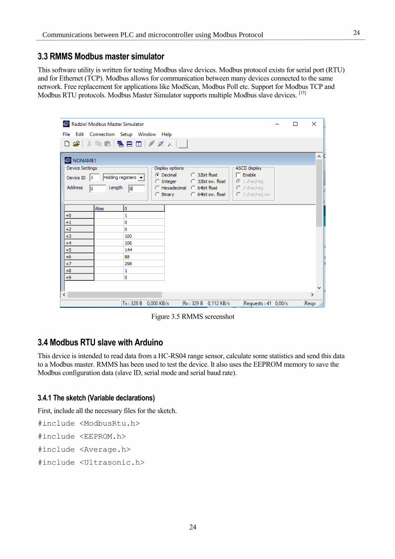
3.2 RMMS Modbus Master simulator
Se ha usado además un software para testear los dispositivos esclavos, ya sean TCP o RTU desde un PC.
RMMS Modbus master simulator soporta además conexión con múltiples esclavos al mismo tiempo.
3.3 Programas Modbus para Arduino
3.3.1 Programa Modbus RTU esclavo para Arduino
Este programa lee datos de un sensor HC-RS04, calcula algunas estadísticas y luego envía la información al
maestro. Se ha usado el RMMS para testear el programa. Además usa la memoria EEPROM para guardar
datos de configuración (número de esclavo, modo de conexión en serie y frecuencia de la conexión).
3.3.2 Programa Modbus TCP esclavo para Arduino y el shield Ethernet
Este programa lee datos de un sensor HC-RS04, calcula algunas estadísticas y luego envía la información al
maestro a través de Ethernet TCP/IP. Se ha usado el RMMS para testear el programa. Además usa la memoria
EEPROM para guardar datos de configuración (como el último byte de la IP).

Resumen en español
xxi
xxi
3.3.3 Programa Modbus RTU maestro para Arduino
Este programa lee datos de un sensor MASS-X que funciona como Modbus esclavo, por lo que se ha
necesitado programar el Arduino como maestro. Luego se mostrará la información leída por la pantalla LCD
la cual se puede ver cómo se conecta en la siguiente imagen:
Figura 3.4 Conexión entre Arduino y pantalla LCD
Para el conexionado hay que usar un adaptador RS485, ya que los puertos del Arduino funcionan a 5V (TTL)
y el sensor con RS-485.
Figura 3.5 Conexión Entre Arduino y módulo RS-485
Los pines DE y RE están conectados al pin 3(se usa este pin porque lo hemos elegido en el programa). El pin
DI va al RX del Arduino y el RO al TX. Los conectores A y B son los RS485+ y RS485- del sensor. El
conversor necesita además una alimentación desde el Arduino. Afortunadamente todavía se dispone de
suficientes tomas de 5V.

xxii
Communications between PLC and microcontroller using Modbus Protocol
xxii
4: Modbus maestro con el M340
Un PLC es un ordenador usado ampliamente en la automatización de procesos electromecánicos en la
industria, como el control de maquinaria en una fábrica, atracciones de feria o las luces de una oficina. Los
PLC se diseñan para múltiples necesidades de entradas y salidas digitales y analógicas, amplios rangos de
temperatura, inmunidad al ruido eléctrico y resistencia frente impactos y vibraciones. Los programas para
controlar la máquina se guardan normalmente en memoria no volátil. Los resultados en las salidas se deben
producir en respuesta a las condiciones de entrada, tanto presente como pasadas.
Figura 4.1 Autómata M340
El M340 de Modicon es un PLC modulable, el cual usa el procesador CMXP34.
Durante este capítulo se explica cómo comunicarnos con el Arduino mediante protocolo Modbus RTU por
cable RS-485, siendo el PLC el dispositivo maestro.
Se han realizado 3 casos de posibles conexiones:
1. Arduino leyendo sensor de distancia y siendo esclavo por Modbus RTU con M340 maestro
2. Arduino leyendo sensor de distancia y siendo esclavo por Modbus TCP con M340 maestro
3. Arduino maestro por Modbus RTU para leer datos del sensor MASS-X y siendo esclavo por Modbus
TCP con M340 maestro
Resumen en español
xxiii
xxiii
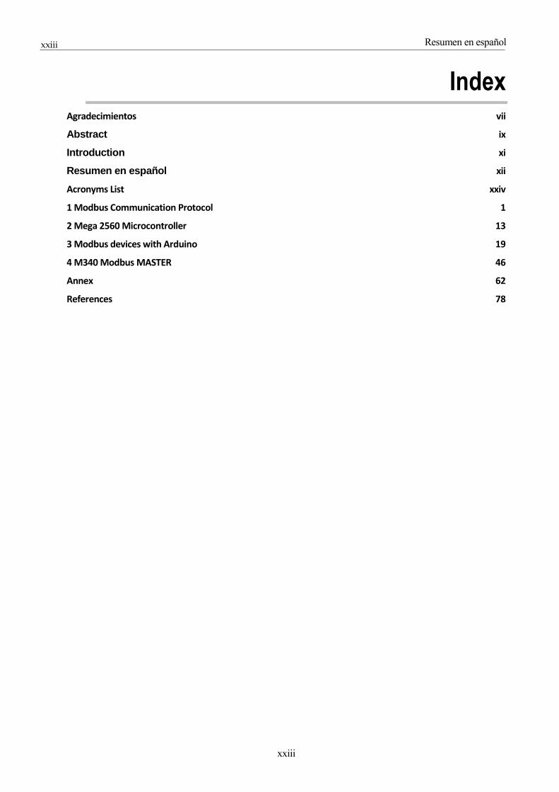
Index Agradecimientos vii
Abstract ix
Introduction xi
Resumen en español xii
Acronyms List xxiv
1 Modbus Communication Protocol 1
2 Mega 2560 Microcontroller 13
3 Modbus devices with Arduino 19
4 M340 Modbus MASTER 46
Annex 62
References 78

xxiv
Communications between PLC and microcontroller using Modbus Protocol
xxiv
ACRONYMS LIST
OSI: Open System Interconnection
TCP/IP: Transmission Control Protocol / Iternet Protocol
PDU: Protocol Data Unit
RTU: Remote Terminal Unit
CRC: Cyclic Redundancy Check
ID: Identification
ASCII: American Standard Code for Information Interchange
LRC: Longitudinal Redundancy Check
ADU: Application Data Unit
CR/LF: Carriage Return / Line Feed
FIFO: First In First Out
UART: Universal Asynchronous Receiver-Transmitter
USB: Universal Serial Bus
TTL: Transistor-Transistor Logic
PWM: Pulse-Width Modulation
AC/DC: Alternating Current / Direct Current
GND: Ground
DHCP: Dynamic Host Configuration Protocol
SD: Secure Digital
SPI: Serial Peripheral Interface
TWI: Two Wire Interface
MAC: Media Access Control
IDE: Integrated Development Environment
EEPROM: Electrically Erasable Programmable Read-Only Memory
SRAM: Static Random Access Memory
LCD: Liquid Crystal Display
I2C: Inter-Integrated Circuit
FOV: Field Of View
PLC: Programmable Logic Controller
LED: Light-Emitting Diode
FB: Function Block

Acronyms List
xxv
xxv

1
1 MODBUS COMMUNICATION PROTOCOL
Modbus is a messaging protocol, positioned at level 7 of the Open System
Interconnection (OSI) model, which provides master/slave communication between devices connected
on different types of buses or networks. The industry’s serial de facto standard since 1979, Modbus
continues to enable millions of automation devices to communicate. Today, support for the simple and
elegant structure of Modbus continues to grow. The Internet community can access Modbus at a reserved
system port 502 on the Transmission Control Protocol / Iternet Protocol (TCP/IP) stack [1]
.
It is a request/reply protocol and offers services specified by function codes. Modbus function codes are
elements of Modbus request/reply Protocol Data Unit (PDU). The objective of this chapter is to describe
the function codes used within the framework of Modbus transactions. [1]
Figure 1.1 OSI Model

2
Communications between PLC and microcontroller using Modbus Protocol
2
1.1 General description
1.1.1 Object types:
Depending on how long is the type or if it is writeable, it is possible to classify then into four
different types:
1-Bit 16-Bits
Read-Only Discrete Input Input Register
Read-Write Coil Holding Register
Table 1.1 Modbus data types
1.1.2 Protocol versions
There are different version of the protocol for serial port and Ethernet:
Modbus Remote Terminal Unit (RTU): This version works with serial communication and it
uses binary representation of the data. The RTU format follows the data with a Cyclic
Redundancy Check (CRC) as an error check mechanism to ensure the reliability. Modbus RTU is
the most common implementation available for Modbus. In addition, (ID) must be given to the slave.
Modbus American Standard Code for Information Interchange (ASCII): This version works with
serial communication and it uses ASCII characters. The ASCII format uses a Longitudinal
Redundancy Check (LRC) checksum. Modbus ASCII messages are framed by leading colon (':')
and trailing newline by Carriage Return / Line Feed (CR/LF).
Modbus TCP/IP: This is a variant used for communications over TCP/IP networks, connecting
over port 502. It does not require a checksum calculation as lower layers of the TCP/IP
protocol already provide checksum protection.
Modbus over TCP/IP: This is a Modbus variant that differs from Modbus TCP in that a checksum is included in the payload.
[2]
1.1.3 Communications between devices
Each slave has a unique address. In serial, only the Master is able to initiate a command. On Ethernet, any
device can send out a Modbus command, although usually only one master device does so. A Modbus
command contains the Modbus address of the slave device(1 to 247). Only the intended device will act on
the command, even though other devices might receive it. All Modbus commands contain checksum
information, to allow the recipient to detect transmission errors.
Many modems and gateways support Modbus, as it is a very simple protocol and often copied. Some of
them were specifically designed for this protocol. Different implementations use wireline or wireless
communication. Typical problems that designers have to overcome include high latency and timing
issues.
Modbus Communication Protocol
3
3
1.1.4 Frame format
Modbus frames are called Application Data Unit (ADU) [3]
. In Modbus RTU, these frames are composed
by three elements:
Slave Address (1 byte from 1 to 247)
Protocol Data Unit (PDU)
Error Check (normally a CRC)
However in other versions where the slave address and the error check are implicit inside another
protocol (like TCP/IP), the frame is composed only by the PDU, which is composed by three blocks:
Function code
First element address
Quantity of data requested or data bytes.
Depending on the function, the address and data field may be non-existent.

4
Communications between PLC and microcontroller using Modbus Protocol
4
1.1.5 Data organization
The examples below show two ways of organizing the data in device. There are different organizations
possible, but not all are described in this document. Each device can have its own organization of the data according to its application:
4 different data blocks: there is no correlation between data blocks
Figure 1.2 Data model with separated blocks[1]
Only one data block: the data can be reached by several Modbus functions
Figure 1.3 One-block data model [1]
1.1.6 Function codes

Modbus Communication Protocol
5
5
The various reading, writing and other public operations are categorised as follows. The most primitive reads
and writes are shown in bold.
Table 1.2 Table of public function codes [4]
There are more public functions, however some functions can be user define and others currently used by
some companies for legacy products and that are not available for public use.
1.2 Data format of main function codes [1]
This section gives details of data format of function codes 01, 02, 03, 04, 05, 06, 15 and 16
1.2.1 Function 1 (0x01) Read coils
This function code is used to read from one to 2000 contiguous status of coils (bits) in a remote device. This
function will return the state of the requested coils and how many Bytes where needed to answer.
Request:
Data type Size Range of values
Function Code 1 Byte 0x01
Starting Address 2 Bytes 0x0000 to 0xFFFF
Quantity of Coils 2 Bytes 0x0001 to 0x07D0 (2000)
6
Communications between PLC and microcontroller using Modbus Protocol
6
Response:
Data type Size Range of values
Function Code 1 Byte 0x01
Byte Count 1 Byte N*
Coil Status N Bytes
*N = Quantity of Outputs / 8, if the remainder is different of 0 then N = N+1
Error:
Data type Size Range of values
Function Code 1 Byte 0x81
Exception Code 1 Byte 0x01 or 0x02 or 0x03 or 0x04
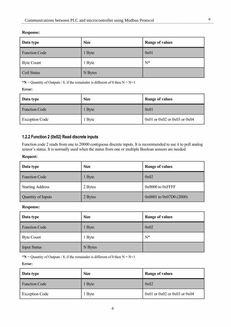
1.2.2 Function 2 (0x02) Read discrete inputs
Function code 2 reads from one to 20000 contiguous discrete inputs. It is recommended to use it to poll analog
sensor’s status. It is normally used when the status from one or multiple Boolean sensors are needed.
Request:
Data type Size Range of values
Function Code 1 Byte 0x02
Starting Address 2 Bytes 0x0000 to 0xFFFF
Quantity of Inputs 2 Bytes 0x0001 to 0x07D0 (2000)
Response:
Data type Size Range of values
Function Code 1 Byte 0x02
Byte Count 1 Byte N*
Input Status N Bytes
*N = Quantity of Outputs / 8, if the remainder is different of 0 then N = N+1
Error:
Data type Size Range of values
Function Code 1 Byte 0x82
Exception Code 1 Byte 0x01 or 0x02 or 0x03 or 0x04

Modbus Communication Protocol
7
7
1.2.3 Function 3 (0x03) Read holding registers
This function reads contiguous blocks of registers (16-Bits). It will return the number of Bytes and the data
saved inside the registers.
Request:
Data type Size Range of values
Function Code 1 Byte 0x03
Starting Address 2 Bytes 0x0000 to 0xFFFF
Quantity of Registers 2 Bytes 0x0001 to 0x07D0 (2000)
Response:
Data type Size Range of values
Function Code 1 Byte 0x03
Byte Count 1 Byte 2 x N*
Register Status 2 x N Bytes
*N = Number of registers
Error:
Data type Size Range of values
Function Code 1 Byte 0x83
Exception Code 1 Byte 0x01 or 0x02 or 0x03 or 0x04
1.2.4 Function 4 (0x04) Read input registers
Function four returns from one to 20000 contiguous input registers. It works like function 3, however it is
normally used to get data from analog sensors in 16-bits registers
Request:
Data type Size Range of values
Function Code 1 Byte 0x04
Starting Address 2 Bytes 0x0000 to 0xFFFF
Quantity of Registers 2 Bytes 0x0001 to 0x07D0 (2000)
8
Communications between PLC and microcontroller using Modbus Protocol
8
Response:
Data type Size Range of values
Function Code 1 Byte 0x04
Byte Count 1 Byte 2 x N*
Register Status 2 x N Bytes
*N = Number of registers
Error:
Data type Size Range of values
Function Code 1 Byte 0x84
Exception Code 1 Byte 0x01 or 0x02 or 0x03 or 0x04
1.2.5 Function 5 (0x05) Write single coil
This function allows writing a single bit. If 0xFF00 is sent in the request data field, the bit will be set to ON. If
0x0000 is sent instead, the bit will be OFF. It will also return the output address in the response PDU.
Request:
Data type Size Range of values
Function Code 1 Byte 0x05
Output Address 2 Bytes 0x0000 to 0xFFFF
Output Value 2 Bytes 0x0000 or 0xFF00
Response:
Data type Size Range of values
Function Code 1 Byte 0x05
Output Address 2 Bytes 0x0000 to 0xFFFF
Output Value 2 Bytes 0x0000 or 0xFF00
*N = Number of registers
Error:

Modbus Communication Protocol
9
9
Data type Size Range of values
Function Code 1 Byte 0x85
Exception Code 1 Byte 0x01 or 0x02 or 0x03 or 0x04
1.2.6 Function 6 (0x06) Write single holding register
This function writes one 16-bit register into the holding register data block. It will also return the value in the
response PDU.
Request:
Data type Size Range of values
Function Code 1 Byte 0x06
Output Address 2 Bytes 0x0000 to 0xFFFF
Register Value 2 Bytes 0x0000 to 0xFFFF
Response:
Data type Size Range of values
Function Code 1 Byte 0x06
Output Address 2 Bytes 0x0000 to 0xFFFF
Register Value 2 Bytes 0x0000 to 0xFFFF
*N = Number of registers
Error:
Data type Size Range of values
Function Code 1 Byte 0x86
Exception Code 1 Byte 0x01 or 0x02 or 0x03 or 0x04
1.2.7 Function 15 (0x0F) Write multiple coils
This function writes data in a sequence of coils. The next example explains pretty well how the data is sent.
Ten contiguous coils are written, starting at coil 20. The request data contents are two bytes: 0xCD01 (1100
1101 0000 0001). The binary bits correspond to the outputs in the following way:
Value 1 1 0 0 1 1 0 1 0 0 0 0 0 0 0 1
Address 27 26 25 24 23 22 21 20 - - - - - - 29 28
Table 1.3 Function 15 PDU example

10
Communications between PLC and microcontroller using Modbus Protocol
10
The first byte transmitted addresses outputs 27-20, with the least significant bit addressing the lowest
output (20) in this set [1]
.
The next byte transmitted (01 hex) addresses outputs 29-28, with the least significant bit addressing the
lowest output (28) in this set. Unused bits in the last data byte should be zero– filled [1]
.
Request:
Data type Size Range of values
Function Code 1 Byte 0x0F
Starting Address 2 Bytes 0x0000 to 0xFFFF
Quantity of Outputs 2 Bytes 0x0001 to 0x07B0
Byte Count 1 Byte N*
Outputs Value N*Byte
*N = Quantity of Outputs / 8, if the remainder is different of 0 then N = N+1
Response:
Data type Size Range of values
Function Code 1 Byte 0x0F
Starting Address 2 Bytes 0x0000 to 0xFFFF
Quantity of Outputs 2 Bytes 0x0001 to 0x07B0
Error:
Data type Size Range of values
Function Code 1 Byte 0x8F
Exception Code 1 Byte 0x01 or 0x02 or 0x03 or 0x04
Modbus Communication Protocol
11
11
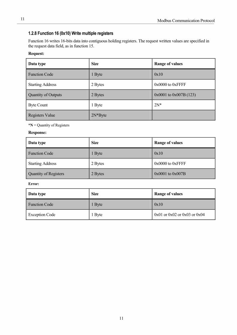
1.2.8 Function 16 (0x10) Write multiple registers
Function 16 writes 16-bits data into contiguous holding registers. The request written values are specified in
the request data field, as in function 15.
Request:
Data type Size Range of values
Function Code 1 Byte 0x10
Starting Address 2 Bytes 0x0000 to 0xFFFF
Quantity of Outputs 2 Bytes 0x0001 to 0x007B (123)
Byte Count 1 Byte 2N*
Registers Value 2N*Byte
*N = Quantity of Registers
Response:
Data type Size Range of values
Function Code 1 Byte 0x10
Starting Address 2 Bytes 0x0000 to 0xFFFF
Quantity of Registers 2 Bytes 0x0001 to 0x007B
Error:
Data type Size Range of values
Function Code 1 Byte 0x10
Exception Code 1 Byte 0x01 or 0x02 or 0x03 or 0x04
12
Communications between PLC and microcontroller using Modbus Protocol
12
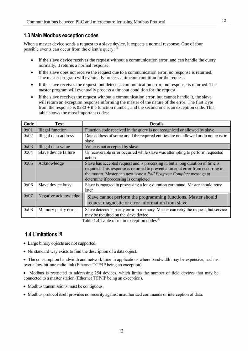
1.3 Main Modbus exception codes
When a master device sends a request to a slave device, it expects a normal response. One of four
possible events can occur from the client’s query: [1]
If the slave device receives the request without a communication error, and can handle the query
normally, it returns a normal response.
If the slave does not receive the request due to a communication error, no response is returned.
The master program will eventually process a timeout condition for the request.
If the slave receives the request, but detects a communication error, no response is returned. The
master program will eventually process a timeout condition for the request.
If the slave receives the request without a communication error, but cannot handle it, the slave
will return an exception response informing the master of the nature of the error. The first Byte
from the response is 0x80 + the function number, and the second one is an exception code. This
table shows the most important codes:
Code Text Details
0x01 Illegal function Function code received in the query is not recognized or allowed by slave
0x02 Illegal data address Data address of some or all the required entities are not allowed or do not exist in
slave
0x03 Illegal data value Value is not accepted by slave
0x04 Slave device failure Unrecoverable error occurred while slave was attempting to perform requested
action
0x05 Acknowledge Slave has accepted request and is processing it, but a long duration of time is
required. This response is returned to prevent a timeout error from occurring in
the master. Master can next issue a Poll Program Complete message to
determine if processing is completed
0x06 Slave device busy Slave is engaged in processing a long-duration command. Master should retry
later
0x07 Negative acknowledge
Slave cannot perform the programming functions. Master should
request diagnostic or error information from slave
0x08 Memory parity error Slave detected a parity error in memory. Master can retry the request, but service
may be required on the slave device
Table 1.4 Table of main exception codes[4]
1.4 Limitations [4]
Large binary objects are not supported.
No standard way exists to find the description of a data object.
The consumption bandwidth and network time in applications where bandwidth may be expensive, such as
over a low-bit-rate radio link (Ethernet TCP/IP being an exception).
Modbus is restricted to addressing 254 devices, which limits the number of field devices that may be
connected to a master station (Ethernet TCP/IP being an exception).
Modbus transmissions must be contiguous.
Modbus protocol itself provides no security against unauthorized commands or interception of data.

Mega 2560 Microcontroller
13
13
2 MEGA 2560 MICROCONTROLLER
The Arduino Mega 2560 is a microcontroller board based on the ATmega2560. It has 54 digital
input/output pins (of which 15 can be used as Pulse-Width Modulation (PWM) outputs), 16 analog inputs, 4
Universal Asynchronous Receiver-Transmitter (UART), a 16 MHz crystal oscillator, a Universal Serial Bus
(USB) connection, a power jack, an ICSP header, and a reset button. It contains everything needed to support
the microcontroller simply connect it to a computer with a USB cable or power it with an Alternating Current /
Direct Current (AC/DC) adapter or battery to get started. The Mega 2560 board is compatible with most
shields designed for the Arduino Uno [5].
Figure 2.1 Two Mega 2560 boards
[5]

14
Communications between PLC and microcontroller using Modbus Protocol
14
2.1 Technical specifications
Microcontroller ATmega2560
Operating Voltage 5 V
Input Voltage (recommended) 7-12 V
Input Voltage (limit) 20 V
Digital I/O Pins 54 (of which 15 provide PWM output)
Analog Input Pins 16
DC Current per I/O Pin 20 mA
DC Current for 3.3V Pin 50 mA
Flash Memory 256 KB of which 8 KB used by boot loader
SRAM 8 KB
EEPROM 4 KB
Clock Speed 16 MHz
Length 101.52 mm
Width 53.3 mm
Weight 37 g (without any external shield)
Table 2.1 Mega 2560 board specifications [5]
2.2 Programming
The Mega 2560 board can be programmed with the Arduino Software Integrated Development Environment
(IDE).
The ATmega2560 on the Mega 2560 comes pre-programmed with a boot loader that allows uploading new
code to it without the use of an external hardware programmer. It communicates using C headers.
The ATmega16U2 (or 8U2 in the rev1 and rev2 boards) firmware source code is available in the Arduino
repository. [5]
2.3 Power [5]
The Mega 2560 can be powered via the USB connection or with an external power supply. The power
source is selected automatically.
External (non-USB) power can come from either an AC-to-DC adapter (wall-wart) or battery. The
adapter can be connected by plugging a 2.1mm centre-positive plug into the board's power jack. Leads
from a battery can be inserted in the Ground (GND) and Vin pin headers of the POWER connector.
Mega 2560 Microcontroller
15
15
The board can operate on an external supply of 6 to 20 volts. If supplied with less than 7V, however, the
5V pin may supply less than five volts and the board may become unstable. If using more than 12V, the
voltage regulator may overheat and damage the board. The recommended range is 7 to 12 volts.
The power pins are as follows:
Vin. The input voltage to the board when it is using an external power source (as opposed to 5
volts from the USB connection or other regulated power source). Voltage can be supply through
this pin, or, if supplying voltage via the power jack, access it through this pin.
5V. This pin outputs a regulated 5V from the regulator on the board. The board can be supplied
with power either from the DC power jack (7 - 12V), the USB connector (5V), or the VIN pin of
the board (7-12V). Supplying voltage via the 5V or 3.3V pins bypasses the regulator, and can
damage the board.
3V3. A 3.3 volt supply generated by the on-board regulator. Maximum current draw is 50 mA.
GND. Ground pins.
IOREF. This pin on the board provides the voltage reference with which the microcontroller
operates. A properly configured shield can read the IOREF pin voltage and select the appropriate
power source or enable voltage translators on the outputs for working with the 5V or 3.3V.
2.4 Memory
The ATmega2560 has 256 KB of flash memory for storing code (of which 8 KB is used for the boot loader), 8
KB of Static Random Access Memory (SRAM) and 4 KB of Electrically Erasable Programmable Read-Only
Memory (EEPROM) (which can be read and written with the EEPROM library). [5]
2.5 Input and Output
Each of the 54 digital pins on the Mega can be used as an input or output, using pinMode(), digitalWrite(), and
digitalRead() functions. They operate at 5 volts. Each pin can provide or receive 20 mA as recommended
operating condition and has an internal pull-up resistor (disconnected by default) of 20-50 k ohm. A maximum
of 40mA is the value that must not be exceeded to avoid permanent damage to the microcontroller. [5]
In addition, some pins have specialized functions:
Serial: 0 (RX) and 1 (TX); Serial 1: 19 (RX) and 18 (TX); Serial 2: 17 (RX) and 16 (TX); Serial 3: 15
(RX) and 14 (TX). Used to receive (RX) and transmit (TX) Transistor-Transistor Logic (TTL) serial
data. Pins 0 and 1 are also connected to the corresponding pins of the ATmega16U2 USB-to-TTL
Serial chip.
External Interrupts: 2 (interrupt 0), 3 (interrupt 1), 18 (interrupt 5), 19 (interrupt 4), 20 (interrupt 3),
and 21 (interrupt 2). These pins can be configured to trigger an interrupt on a low level, a rising or
falling edge, or a change in level. See the attachinterrupt() function for details.
PWM: 2 to 13 and 44 to 46. Provide 8-bit PWM output with the analogWrite() function.
Serial Peripheral Interface (SPI): 50 (MISO), 51 (MOSI), 52 (SCK), 53 (SS). These pins support SPI
communication using the SPI library. The SPI pins are also broken out on the ICSP header, which is
physically compatible with the Arduino /Genuino Uno and the old Duemilanove and Diecimila
Arduino boards.
LED: 13. There is a built-in Light-Emitting Diode (LED) connected to digital pin 13. When the pin is
HIGH value the LED is on when the pin is LOW, it is off.
Two Wire Interface (TWI): 20 (SDA) and 21 (SCL). Support TWI communication using the Wire
library. Note that these pins are not in the same location as the TWI pins on the old Duemilanove or
Diecimila Arduino boards.
The Mega 2560 has 16 analog inputs, each of which provide 10 bits of resolution (i.e. 1024 different values).
16
Communications between PLC and microcontroller using Modbus Protocol
16
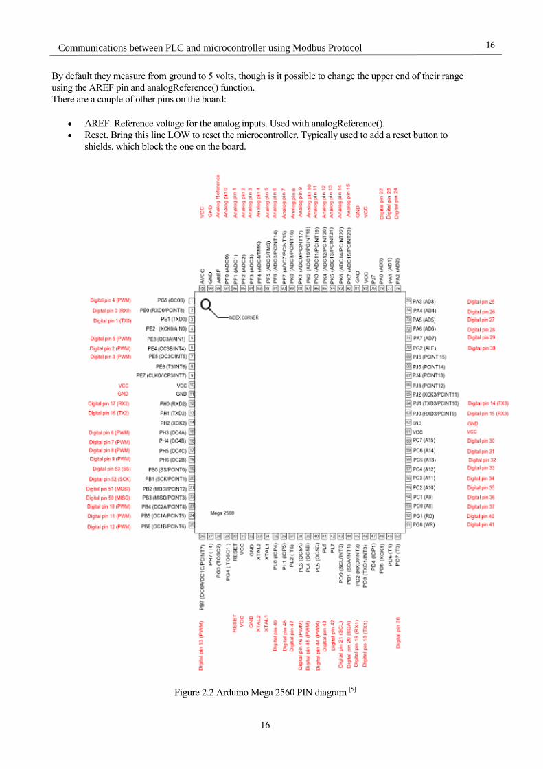
By default they measure from ground to 5 volts, though is it possible to change the upper end of their range
using the AREF pin and analogReference() function.
There are a couple of other pins on the board:
AREF. Reference voltage for the analog inputs. Used with analogReference().
Reset. Bring this line LOW to reset the microcontroller. Typically used to add a reset button to
shields, which block the one on the board.
Figure 2.2 Arduino Mega 2560 PIN diagram [5]

Mega 2560 Microcontroller
17
17
2.6 Communication
The Mega 2560 board has a number of facilities for communicating with a computer, another board, or other
microcontrollers. The ATmega2560 provides four hardware UARTs for TTL (5V) serial communication. An
ATmega16U2 (ATmega 8U2 on the revision 1 and revision 2 boards) on the board channels one of these over
USB and provides a virtual com port to software on the computer (Windows machines will need a .inf file, but
OSX and Linux machines will recognize the board as a COM port automatically. The Arduino Software (IDE)
includes a serial monitor, which allows simple textual data to be sent to and from the board. The RX and TX
LEDs on the board will flash when data is being transmitted via the ATmega8U2/ATmega16U2 chip and USB
connection to the computer (but not for serial communication on pins 0 and 1).
A SoftwareSerial library allows for serial communication on any of the Mega 2560's digital pins.
The Mega 2560 also supports TWI and SPI communication. The Arduino Software (IDE) includes a Wire
library to simplify use of the TWI bus; see the documentation for details. For SPI communication, use the SPI
library. [5]
2.7 Shield Compatibility
The maximum length and width of the Mega 2560 PCB are 4 and 2.1 inches respectively, with the USB
connector and power jack extending beyond the former dimension. Three screw holes allow the board to
be attached to a surface or case. Note that the distance between digital pins 7 and 8 is 160 mil (0.16"), not
an even multiple of the 100 mil spacing of the other pins.
The Mega 2560 is designed to be compatible with most shields designed for the Uno and the older
Diecimila or Duemilanove Arduino boards. Digital pins 0 to 13 (and the adjacent AREF and GND pins),
analog inputs 0 to 5, the power header, and ICSP header are all in equivalent locations. Furthermore, the
main UART (serial port) is located on the same pins (0 and 1), as are external interrupts 0 and 1 (pins 2
and 3 respectively). SPI is available through the ICSP header on both the Mega 2560 and Duemilanove /
Diecimila boards. Please note that Inter-Integrated Circuit (I2C) is not located on the same pins on the
Mega 2560 board (20 and 21) as the Duemilanove / Diecimila boards (analog inputs 4 and 5). [5]
18
Communications between PLC and microcontroller using Modbus Protocol
18
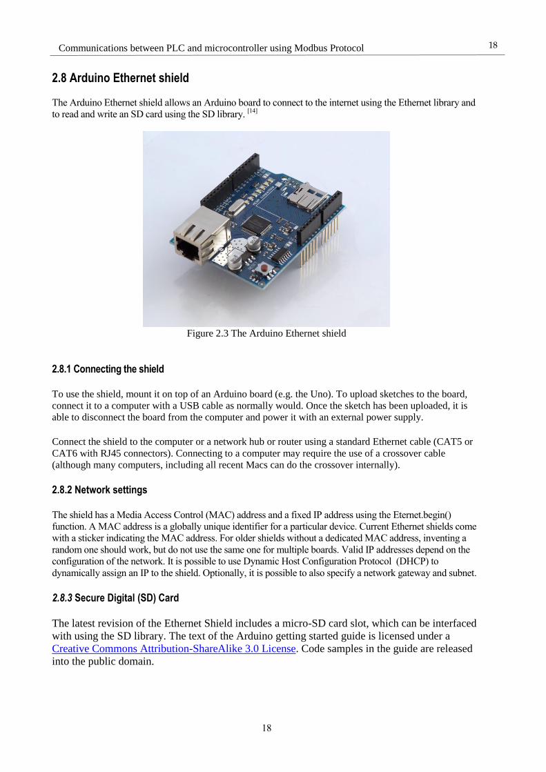
2.8 Arduino Ethernet shield The Arduino Ethernet shield allows an Arduino board to connect to the internet using the Ethernet library and
to read and write an SD card using the SD library. [14]
Figure 2.3 The Arduino Ethernet shield
2.8.1 Connecting the shield
To use the shield, mount it on top of an Arduino board (e.g. the Uno). To upload sketches to the board,
connect it to a computer with a USB cable as normally would. Once the sketch has been uploaded, it is
able to disconnect the board from the computer and power it with an external power supply.
Connect the shield to the computer or a network hub or router using a standard Ethernet cable (CAT5 or
CAT6 with RJ45 connectors). Connecting to a computer may require the use of a crossover cable
(although many computers, including all recent Macs can do the crossover internally).
2.8.2 Network settings
The shield has a Media Access Control (MAC) address and a fixed IP address using the Eternet.begin()
function. A MAC address is a globally unique identifier for a particular device. Current Ethernet shields come
with a sticker indicating the MAC address. For older shields without a dedicated MAC address, inventing a
random one should work, but do not use the same one for multiple boards. Valid IP addresses depend on the
configuration of the network. It is possible to use Dynamic Host Configuration Protocol (DHCP) to
dynamically assign an IP to the shield. Optionally, it is possible to also specify a network gateway and subnet.
2.8.3 Secure Digital (SD) Card
The latest revision of the Ethernet Shield includes a micro-SD card slot, which can be interfaced
with using the SD library. The text of the Arduino getting started guide is licensed under a
Creative Commons Attribution-ShareAlike 3.0 License. Code samples in the guide are released
into the public domain.

3 Modbus devices with Arduino
19
19
3 MODBUS DEVICES WITH ARDUINO
This chapter explains how some full functional Modbus devices using an Arduino MEGA board were
developed and which tools were used. The main goal of this device would be to read data from sensors,
storage the data, calculate some statistics and send the data to a master when this master sends a valid request
frame.
3.1 Arduino IDE
The open-source Arduino Software (IDE) makes it easy to write code and upload it to the board. It runs on
Windows, Mac OS X, and Linux. The environment is written in Java and based on Processing and other open-
source software. This software can be used with any Arduino board. [6]
20
Communications between PLC and microcontroller using Modbus Protocol
20
Figure 3.1 Arduino IDE Screenshot
3.2 Libraries
The Arduino environment can be extended with libraries, just like most programming platforms. Libraries
provide extra functionality for use in sketches, e.g. working with hardware or manipulating data.
A number of libraries come installed with the IDE, but it is also possible to install then or even make new
libraries. [7]
Like in C, all the libraries name must end by the extension .h
3.2.1 EEPROM.h
The microcontroller on the Arduino and Genuino AVR based board has EEPROM: memory whose values are
kept when the board is turned off (like a tiny hard drive). This library enables to read and write those bytes. [8]
The most important functions from this library are:
EEPROM.read() Reads a byte from the EEPROM. Locations that have never been written to have the
value of 255.
EEPROM.write() Write a byte to the EEPROM.
EEPROM.update() Write a byte to the EEPROM. The value is written only if differs from the one already
saved at the same address. An EEPROM write takes 3.3 ms to complete. The EEPROM
memory has a specified life of 100,000 write/erase cycles, so using this function instead
of write() can save cycles if the written data does not change often.
Table 3.1 Table of EEMPROM.h functions [8]
3 Modbus devices with Arduino
21
21
3.2.2 Average.h
This is a collection of routines for performing mathematical analysis of arrays of numbers. [9]
The functions
used during this project are:
Average.rolling() Adds value to the array history_array shifting all the values down one place.
Average.mean() Calculates the mean average of the values in array. slice_count is the number of entries
in the array.
Average.stddev This functions returns the standard deviation. This is the only function, which does not
return the same data type as the array. The standard deviation is always returned as a
float.
Average.maximum() Finds the largest value in the array.
Average.minimum() Finds the smallest value in the array.
Table 3.2 Table of Average.h functions [
3.2.3 Ultrasonic.h
This library functions as an intermediate between the program and the ultrasonic distance sensor HC-RS04.
After creating an object from the class ultrasonic, it is only needed to call its method ultrasonic.Rangin(),
which will return the distance between an object and the sensor. In case of error, a 0 will be returned. [10]
Figure 3.2 Range sensor HC-RS04

22
Communications between PLC and microcontroller using Modbus Protocol
22
3.2.4 ModbusRtu.h
This library provides a Serial Modbus implementation for Arduino. [11]
This works in case of the slave as one
block data device of 16-bits register and is compatible with all the main Modbus function codes. The functions
used in this project are:
Modbus.begin() Starts the serial communication
Modbus.getID() Method to read current slave ID address
Modbus.setID() Method to write a new slave ID address
Modbus.poll() This method checks if there is any incoming query. Afterwards, it would shoot a
validation routine plus a register query. It is recommended not to use any kind of
delay function. After a successful frame between the master and the slave, the time-
out timer is reset.
Modbus.setTimeOut() Initializes time-out parameter
Modbus.query() This includes all the necessary fields to make the master generate a Modbus query. A
master may keep several of these structures and send them cyclically or use them
according to program needs.
Table 3.3 Table of ModbusRtu.h functions [12]
3.2.5 Ethernet.h
With the Arduino Ethernet Shield, this library allows an Arduino board to connect to the internet. It can
serve as either a server accepting incoming connections or a client making outgoing ones. The library
supports up to four concurrent connection (incoming or outgoing or a combination).
Arduino communicates with the shield using the SPI bus. This is on digital pins 11, 12, and 13 on the
Uno and pins 50, 51, and 52 on the Mega. On both boards, pin 10 is used as SS. On the Mega, the
hardware SS pin, 53, is not used to select the W5100, but it must be kept as an output or the SPI interface
will not work. [13]
Figure 3.3 Mega pins used in Ethernet.h [13]
3 Modbus devices with Arduino
23
23
The only function used in this project is Ethernet.begin() which receives as arguments the MAC, IP and subnet
direction.
3.2.5 Mudbus.h
Since frames in RTU are different from frames in TCP, the library ModbusRtu.h is no longer useful if it is
needed to communicate with the device via Ethernet. This library allows us to connect to a distant master in
the same local network or the Internet (this last one is not recommended since lack of security in the protocol),
and it is actually easier to use thanks to the protocol TCP/ which is implemented in Ethernet.h.
The only function needed for an slave is Modbus.Run, which does all the frame handling and generates a
response.
3.2.6 LiquidCrystal_I2C.h
This library is used to show data in a Liquid Crystal Display (LCD) screen compatible with the I2C protocol. It
uses the pins SDA and SCL from them Mega an needs a 5V power supply. It also has a background light and
uses characters as data type to print. The main functions are:
LiquidCrystal_I2C.begin() Initialize the LCD
LiquidCrystal_I2C.backlight() Turn on the back light
LiquidCrystal_I2C.setCursor() Set where the first char will be printed
LiquidCrystal_I2C.pritn() Print a string of chars
Table 3.4 Table of LiquidCrystal_I2C functions [16]
Figure 3.4 16x2 Characters LCD display
24
Communications between PLC and microcontroller using Modbus Protocol
24
3.3 RMMS Modbus master simulator
This software utility is written for testing Modbus slave devices. Modbus protocol exists for serial port (RTU)
and for Ethernet (TCP). Modbus allows for communication between many devices connected to the same
network. Free replacement for applications like ModScan, Modbus Poll etc. Support for Modbus TCP and
Modbus RTU protocols. Modbus Master Simulator supports multiple Modbus slave devices. [15]
Figure 3.5 RMMS screenshot
3.4 Modbus RTU slave with Arduino
This device is intended to read data from a HC-RS04 range sensor, calculate some statistics and send this data
to a Modbus master. RMMS has been used to test the device. It also uses the EEPROM memory to save the
Modbus configuration data (slave ID, serial mode and serial baud rate).
3.4.1 The sketch (Variable declarations)
First, include all the necessary files for the sketch.
#include <ModbusRtu.h>
#include <EEPROM.h>
#include <Average.h>
#include <Ultrasonic.h>
3 Modbus devices with Arduino
25
25
Then define some constants that are widely repeated in this code. If it is necessary to change one it is possible
to do it in these lines, so it is no longer necessary to look at them on the whole sketch. Define two constants for
the loop_timer EEPROM address because it is a 16-bit data, and the EEPROM works with 8 bits per register
(ATMEGA2560 is an 8-bit processor). The history array size is 300, and cannot be much larger. Because 9
registers are needed, that will be the size of the Modbus register, and if needed, it is only necessary to change
this number to reserve more space in memory.
//EEPROM addresses
#define SLAVE_ADDR 0
#define BAUDRATE_ADDR 1
#define SERMODE_ADDR 2
#define LOOP_TIMER_HIGH_ADDR 3
#define LOOP_TIMER_LOW_ADDR 4
#define HISTORY_SIZE 300
#define Modbus_REGISTER_SIZE 9
The next line defines a long object that will later need to set a timer.
unsigned long Timer;
Declaration of a Modbus object with the slave number 1 in the serial port with the code 0 of the Arduino. The
second argument is for choosing the serial port, and the last one is for choosing an enable pin in case an RS-
485 is being used.
Modbus slave (1, 0 , 0); //ID,SerialPort USB or RS-232
Declaration of the state variable which will later be used to store the state of the function Modbus.poll()
byte state = 0;
Declaration of some configuration variables for the serial port, the timer loop timer in milliseconds (100 by
default) and the variable that will storage the data read from the range sensor. uint16_t is an unsigned 16-bit
integer
byte baudRateId = 0;
byte serModeId = 0;
uint16_t loop_timer = 100;
uint16_t measure;
Declaration of the Modbus registers array and the history array for the calculation of statistics.
uint16_t au16data[Modbus_REGISTER_SIZE];
Average<uint16_t> history(HISTORY_SIZE);
26
Communications between PLC and microcontroller using Modbus Protocol
26
Declaration of the Ultrasonic object. The trigger pin will be the 22 and the echo the 24.
Ultrasonic ultrasonic(22,24); // (Trig PIN,Echo PIN)
3.4.2 The sketch (Setup)
The setup function is called in the Arduino just one time before the function loop is called.
void setup() {}
Configuration of the slave ID: This will get the ID from the EEPROM. If the number is 0, 1 will be set as slave
number and storage in the EERPOM. Finally, the data will be saved in the Modbus register.
//Setup Slave number
slave.setID(EEPROM.read(SLAVE_ADDR));
if (slave.getID() == 0) {
EEPROM.write(SLAVE_ADDR, 1);
slave.setID(1);
}
au16data[0] = uint16_t(slave.getID());
Configuration and start of serial communications. The beginSerial will be defined later on.
//configure and start communications
baudRateId = EEPROM.read(BAUDRATE_ADDR);
serModeId = EEPROM.read(SERMODE_ADDR);
au16data[1] = uint16_t(baudRateId);
au16data[2] = uint16_t(serModeId);
beginSerial(baudRateId, serModeId);
Configuration of the loop timer from the EEPROM. If a 0 is read from the memory, the timer will be set to
100 milliseconds. The two Bytes from the EERPOM must be parsed to a unsigned 16-bit integer, and parsed
again into two Bytes.
//configure loop timer
loop_timer = (uint16_t)EEPROM.read(LOOP_TIMER_HIGH_ADDR);
loop_timer = loop_timer << 8;
loop_timer |= (uint16_t)EEPROM.read(LOOP_TIMER_LOW_ADDR);
if (loop_timer == 0) {
loop_timer = 100;
EEPROM.write(LOOP_TIMER_LOW_ADDR, loop_timer);
EEPROM.write(LOOP_TIMER_HIGH_ADDR, loop_timer >> 8);

3 Modbus devices with Arduino
27
27
}
loop_timer << 8;
au16data[3] = loop_timer;
The function millis returns the milliseconds since the Arduino turned ON. Then storage this data into the timer
variable.
Timer = millis();
3.4.3 The sketch (Loop)
This function is called repeatedly after the setup function until the Arduino is turned OFF.
void loop() {}
The function Modbus.poll() gets the frame from the master, and prepares an sends a response PDU to the
master with the data from the Modbus register.
state = slave.poll(au16data, Modbus_REGISTER_SIZE);
Ask if the timer has finished. If it is, then call the function reg_poll to read a new input from the sensor. Notice
that millis() will come back to 0 after a certain time (50 days approx.). After that, the timer is reset.
if ((millis() - Timer > loop_timer) | (millis() - Timer < 0)) {
//poll messages
reg_poll();
Timer = millis();
}
28
Communications between PLC and microcontroller using Modbus Protocol
28
3.4.4 The sketch (reg_poll function)
This function is called once per timer reset.
void reg_poll() {}
Get an input from the sensor, roll it into the history array and calculate some statistics.
measure = ultrasonic.Ranging(CM);
history.rolling(measure);
au16data[4] = uint16_t(measure);
au16data[5] = history.mean();
au16data[6] = history.stddev();
au16data[7] = history.maximum();
au16data[8] = history.minimum();
Look up to updates from the Modbus master in the configuration variables (slave ID, baud rate, serial mode
and loop timer)
if (uint16_t(slave.getID()) != au16data[0]) {
slave.setID(uint8_t(au16data[0]));
EEPROM.update(SLAVE_ADDR, byte(au16data[0]));
}
if (uint16_t(baudRateId ) != au16data[1]) {
baudRateId = au16data[1];
Serial.end();
beginSerial(baudRateId, serModeId);
EEPROM.update(BAUDRATE_ADDR, byte(au16data[1]));
}
if (uint16_t(serModeId) != au16data[2]) {
serModeId = au16data[2];
Serial.end();
beginSerial(baudRateId, serModeId);
EEPROM.update(SERMODE_ADDR, byte(au16data[2]));
}
if (loop_timer != au16data[3]) {
3 Modbus devices with Arduino
29
29
loop_timer = au16data[3];
EEPROM.write(LOOP_TIMER_LOW_ADDR, loop_timer);
EEPROM.write(LOOP_TIMER_HIGH_ADDR, loop_timer >> 8);
loop_timer << 8;
}
3.4.5 The sketch (beginSerial function)
This function setups and begins the communication between the serial and the Modbus. It receives the baud
rate and serial mode IDs, instead of the actual values, because the ID size is only 1 Byte, se same size as the
EERPROM registers.
void beginSerial(byte baudRateId, byte serModeId) {}
Call a function, which returns the actual value of the baud rate from the ID
long baudRate = getBaudRate(baudRateId);
Begin the serial communications with the chosen serial mode.
switch (serModeId) {
case 0: slave.begin(baudRate, SERIAL_8N1); break;
case 1: slave.begin(baudRate, SERIAL_8N2); break;
case 2: slave.begin(baudRate, SERIAL_8E1); break;
case 3: slave.begin(baudRate, SERIAL_8E2); break;
case 4: slave.begin(baudRate, SERIAL_8O1); break;
case 5: slave.begin(baudRate, SERIAL_8O2); break;
case 6: slave.begin(baudRate, SERIAL_7N1); break;
case 7: slave.begin(baudRate, SERIAL_7N2); break;
case 8: slave.begin(baudRate, SERIAL_7E1); break;
case 9: slave.begin(baudRate, SERIAL_7E2); break;
case 10: slave.begin(baudRate, SERIAL_7O1); break;
case 11: slave.begin(baudRate, SERIAL_7O2); break;
default: slave.begin(baudRate, SERIAL_8N1); break;
}
3.4.5 The sketch (getBaudRate function)
As said before, this function receives the baud rate ID and returns the actual baud rate value.
long getBaudRate(byte baudRateId) {
long baudRate;
switch (baudRateId) {

30
Communications between PLC and microcontroller using Modbus Protocol
30
case 0: baudRate = 9600; break;
case 1: baudRate = 300; break;
case 2: baudRate = 600; break;
case 3: baudRate = 1200; break;
case 4: baudRate = 2400; break;
case 5: baudRate = 4800; break;
case 6: baudRate = 14400; break;
case 7: baudRate = 19200; break;
case 8: baudRate = 28800; break;
case 9: baudRate = 38400; break;
case 10: baudRate = 57600; break;
case 11: baudRate = 115200; break;
default: baudRate = 9600; break;
}
return baudRate;
}
3.4.6 List of variable addresses in memory
Address Modbus Register EEPROM
0 Slave ID Slave ID
1 Baud rate ID Baud rate ID
2 Serial mode ID Serial mode ID
3 Loop timer Loop timer high Byte
4 Last read value from the sensor Loop timer low Byte
5 Mean average
6 Standard variation
7 Maximum
8 Minimum
Table 3.5 List of variable addresses

3 Modbus devices with Arduino
31
31
3.4.6 List of baud rate a serial mode ID
ID
Baud Rate
Serial Mode
Bit number Parity Stop Bits
0 (Default) 9600 8 None 1
1 300 8 None 2
2 600 8 Even 1
3 1200 8 Even 2
4 2400 8 Odd 1
5 4800 8 Odd 2
6 14400 7 None 1
7 19200 7 None 2
8 28800 7 Even 1
9 38400 7 Even 2
10 57600 7 Odd 1
11 115200 7 Odd 2
Table 3.6 List of ID

32
Communications between PLC and microcontroller using Modbus Protocol
32
3.5 Modbus TCP slave with Arduino and the Ethernet shield
This device is intended to read data from a HC-RS04 range sensor, calculate some statistics and send this data
to a Modbus master trough Ethernet TCP/IP. The RMMS was used to test the device. It also uses the
EEPROM memory to save the last byte of the IP.
Figure 3.6 Arduino Mega with the Ethernet Shield
3.4.1 The sketch (Variable declarations)
First of all, include all the necessary libraries. SPI.h is used to communicate with the Ethernet shield.
#include <Ethernet.h>
#include <SPI.h>
#include <Mudbus.h>
#include <EEPROM.h>
#include <Average.h>
#include <Ultrasonic.h>
Then, define all the constants.
//EEPROM addresses
#define IP_ADDR 0
#define LOOP_TIMER_HIGH_ADDR 1
#define LOOP_TIMER_LOW_ADDR 2
#define HISTORY_SIZE 300
#define Modbus_REGISTER_SIZE 7
3 Modbus devices with Arduino
33
33
Next, declare the Timer variable, the Modbus object, the IP variable and the measure variable as done on the
RTU.
unsigned long Timer;
Mudbus Mb;
uint8_t ipB = 1;
uint16_t loop_timer = 100;
uint16_t measure;
Again, declare the history array and the Modbus register array.
uint16_t au16data[Modbus_REGISTER_SIZE];
Average<uint16_t> history(HISTORY_SIZE);
Declaration of the Ultrasonic object. The trigger pin will be the 22 and the echo the 24.
Ultrasonic ultrasonic(22,24); // (Trig PIN,Echo PIN)
Finally declare the Ethernet settings (IP by default will be 192.168.1.10, but it is possible to change the last
Byte)
// Ethernet settings (depending on MAC and Local network)
byte mac[] = {0x90, 0xA2, 0xDA, 0x0E, 0x94, 0xB5 };
byte ip[] = {192, 168, 1, 10};
byte subnet[] = {255, 255, 255, 0};
3.4.2 The sketch (Setup)
First, read the last Byte of the IP from the EEPROM, as done with the slave ID on the RTU. Then start the
Ethernet interface.
//configure and start communications
ip[3] = EEPROM.read(IP_ADDR);
if (ip[3] == 0) {
ip[3] = 10;
EEPROM.write(IP_ADDR, ip[3]);
}
Mb.R[0] = ip[3];
Ethernet.begin(mac, ip, subnet); // start etehrnet interface

34
Communications between PLC and microcontroller using Modbus Protocol
34
Then take the settings for the loop timer as done before.
//configure loop timer
loop_timer = (uint16_t)EEPROM.read(LOOP_TIMER_HIGH_ADDR);
loop_timer = loop_timer << 8;
loop_timer |= (uint16_t)EEPROM.read(LOOP_TIMER_LOW_ADDR);
if (loop_timer == 0) {
loop_timer = 100;
EEPROM.write(LOOP_TIMER_LOW_ADDR, loop_timer);
EEPROM.write(LOOP_TIMER_HIGH_ADDR, loop_timer >> 8);
}
loop_timer << 8;
Mb.R[1] = loop_timer;
Finally call the function millis() and save the returned data into the Timer variable.
Timer = millis();
3.4.3 The sketch (Loop)
Now call the function Modbus.Run() to poll the request from the master. The rest of the code in this function is
exactly the same as the one written on the Modbus RTU.
void loop() {
Mb.Run();
if ((millis() - Timer > loop_timer) | (millis() - Timer < 0)) {
//poll messages
reg_poll();
Timer = millis();
}
}
3.4.4 The sketch (reg_poll function)
This function is quite similar to the one on the RTU, and will be called once per time reset. First, read data
from the sensor and roll it into the Average array.
measure = ultrasonic.Ranging(CM);
history.rolling(measure);

3 Modbus devices with Arduino
35
35
In addition, storage the measure taken and statistics into the Modbus registers.
Mb.R[2] = uint16_t(measure);
Mb.R[3] = history.mean();
Mb.R[4] = history.stddev();
Mb.R[5] = history.maximum();
Mb.R[6] = history.minimum();
Finally, check is there is an update from the master in the IP or loop timer settings and save it into the
EEPROM.
if (ip[3] != Mb.R[0]) {
ip[3] = Mb.R[0];
EEPROM.write(IP_ADDR, ip[3]);
Ethernet.begin(mac, ip, subnet);
}
if (loop_timer != Mb.R[1]) {
loop_timer = Mb.R[1];
EEPROM.write(LOOP_TIMER_LOW_ADDR, loop_timer);
EEPROM.write(LOOP_TIMER_HIGH_ADDR, loop_timer >> 8);
loop_timer << 8;
}
3.4.5 List of variable addresses in memory
Address Modbus Register EEPROM
0 IP last Byte IP last Byte
1 Loop timer Loop timer high Byte
2 Last read value from the sensor Loop timer low Byte
3 Mean average
4 Standard variation
5 Maximum
6 Minimum
Table 3.7 List of addresses
36
Communications between PLC and microcontroller using Modbus Protocol
36
3.6 Modbus RTU master with Arduino
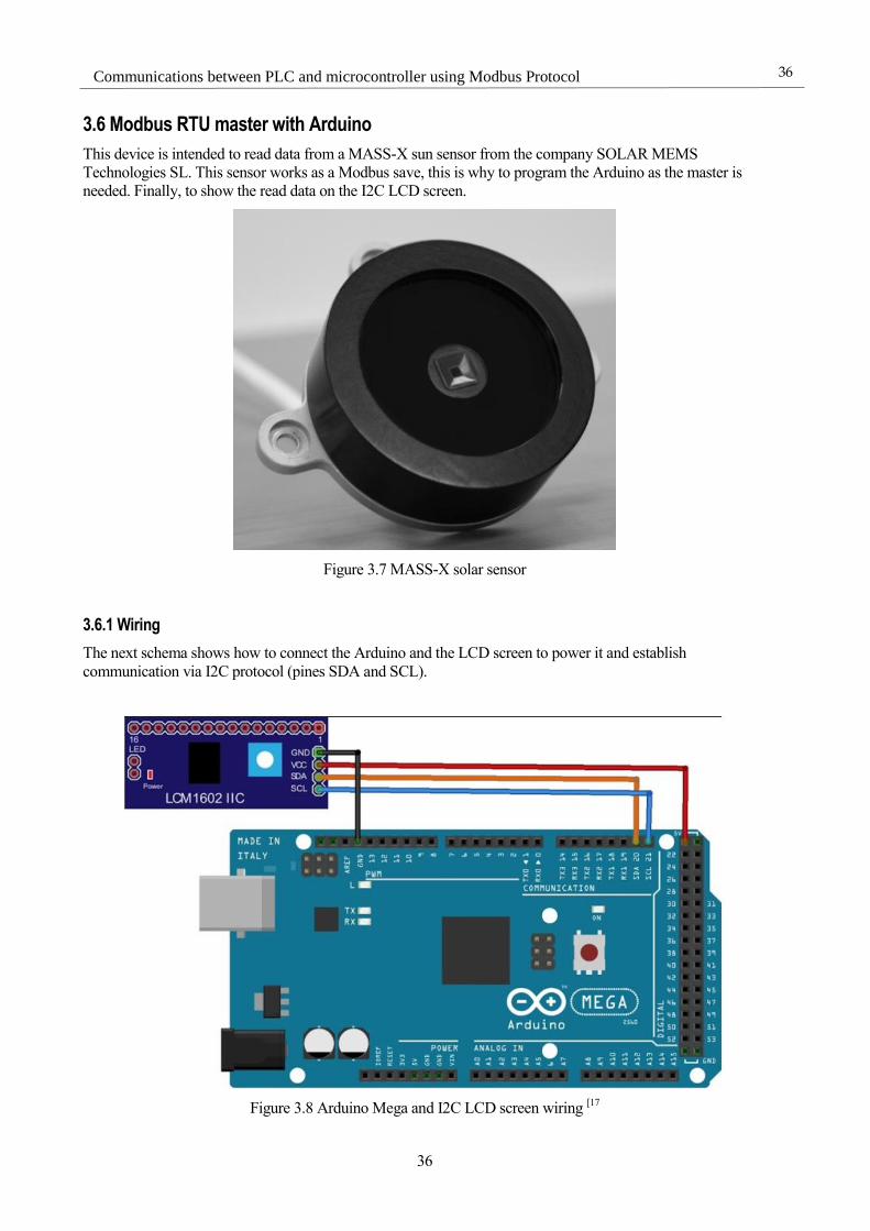
This device is intended to read data from a MASS-X sun sensor from the company SOLAR MEMS
Technologies SL. This sensor works as a Modbus save, this is why to program the Arduino as the master is
needed. Finally, to show the read data on the I2C LCD screen.
Figure 3.7 MASS-X solar sensor
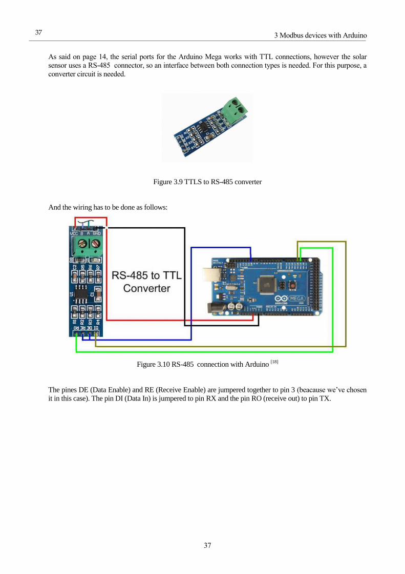
3.6.1 Wiring
The next schema shows how to connect the Arduino and the LCD screen to power it and establish
communication via I2C protocol (pines SDA and SCL).
Figure 3.8 Arduino Mega and I2C LCD screen wiring [17
3 Modbus devices with Arduino
37
37
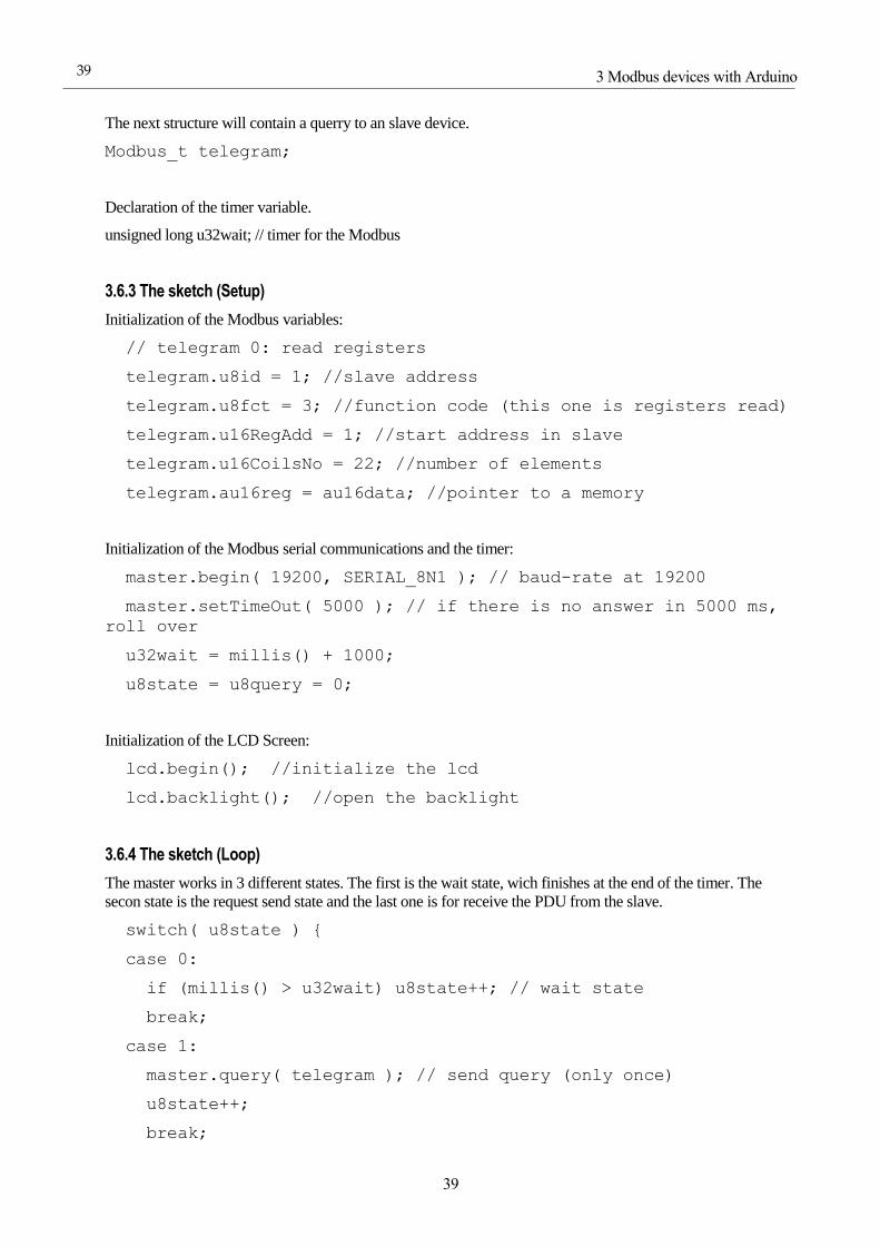
As said on page 14, the serial ports for the Arduino Mega works with TTL connections, however the solar
sensor uses a RS-485 connector, so an interface between both connection types is needed. For this purpose, a
converter circuit is needed.
Figure 3.9 TTLS to RS-485 converter
And the wiring has to be done as follows:
Figure 3.10 RS-485 connection with Arduino [18]
The pines DE (Data Enable) and RE (Receive Enable) are jumpered together to pin 3 (beacause we’ve chosen
it in this case). The pin DI (Data In) is jumpered to pin RX and the pin RO (receive out) to pin TX.

38
Communications between PLC and microcontroller using Modbus Protocol
38
The wires A and B are the wires ‘RS-485 +’ and ‘RS-485 –‘ from the sensor. Notice that the sensor will need
its own power supply from the arduino. Luckily there is enough 5V power supply pines in the Arduino. The
following table shows the color code from the sensor.
Table 3.8 Table of MASS-X electrical interface [19]
3.6.2 The sketch (Variable decarations)
First of all, include all the necessary libraries. SPI.h is used to communicate with the Ethernet shield.
#include <ModbusRtu.h>
#include <Wire.h>
#include <LiquidCrystal_I2C.h>
Then define the constant for the RS-485 control.
#define SSerialTxControl 3 //RS485 Direction control
And now do the declaration of all the Modbus variables:
uint16_t au16data[22]; //!< data array for Modbus network sharing
uint8_t u8state; //!< machine state
uint8_t u8query; //!< pointer to message query
To show data on the scree the lyquid crystal object must be created with 2 rows and 16 colums
LiquidCrystal_I2C lcd(0x27,16,2);
This Modbus object receives as its last argument the control pin for the RS-485 interface.
Modbus master(0,0,SSerialTxControl); // this is master for RS-485
3 Modbus devices with Arduino
39
39
The next structure will contain a querry to an slave device.
Modbus_t telegram;
Declaration of the timer variable.
unsigned long u32wait; // timer for the Modbus
3.6.3 The sketch (Setup)
Initialization of the Modbus variables:
// telegram 0: read registers
telegram.u8id = 1; //slave address
telegram.u8fct = 3; //function code (this one is registers read)
telegram.u16RegAdd = 1; //start address in slave
telegram.u16CoilsNo = 22; //number of elements
telegram.au16reg = au16data; //pointer to a memory
Initialization of the Modbus serial communications and the timer:
master.begin( 19200, SERIAL_8N1 ); // baud-rate at 19200
master.setTimeOut( 5000 ); // if there is no answer in 5000 ms,
roll over
u32wait = millis() + 1000;
u8state = u8query = 0;
Initialization of the LCD Screen:
lcd.begin(); //initialize the lcd
lcd.backlight(); //open the backlight
3.6.4 The sketch (Loop)
The master works in 3 different states. The first is the wait state, wich finishes at the end of the timer. The
secon state is the request send state and the last one is for receive the PDU from the slave.
switch( u8state ) {
case 0:
if (millis() > u32wait) u8state++; // wait state
break;
case 1:
master.query( telegram ); // send query (only once)
u8state++;
break;

40
Communications between PLC and microcontroller using Modbus Protocol
40
case 2:
master.poll(); // check incoming messages
if (master.getState() == COM_IDLE) {
u8state++;
u32wait = millis() + 1000; }
break;
Finally send the data to the LCD screen after the state 2.
case 3:
u8state = 0;
lcd.setCursor(0, 0);
lcd.print("FOV: ");
lcd.print(au16data[1]);
lcd.setCursor(0, 1);
lcd.print("A Info: ");
lcd.print(au16data[7]);
delay(3000);
lcd.clear();
lcd.setCursor(0, 0);
lcd.print("DNI R: ");
lcd.print(au16data[8]);
lcd.setCursor(0, 1);
lcd.print("T: ");
lcd.print(au16data[9]);
delay(3000);
lcd.clear();
lcd.setCursor(0, 0);
lcd.print("FAX: ");
lcd.print(au16data[10]);
lcd.setCursor(0, 1);
lcd.print("FAY: ");
lcd.print(au16data[11]);
delay(3000);

3 Modbus devices with Arduino
41
41
lcd.clear();
lcd.setCursor(0, 0);
lcd.print("AX: ");
lcd.print(au16data[12]);
lcd.setCursor(0, 1);
lcd.print("AY: ");
lcd.print(au16data[13]);
delay(3000);
lcd.clear();
lcd.setCursor(0, 0);
lcd.print("Azi: ");
lcd.print(au16data[14]);
lcd.setCursor(0, 1);
lcd.print("Ele: ");
lcd.print(au16data[15]);
delay(3000);
lcd.clear();
lcd.setCursor(0, 0);
lcd.print("MVX: ");
lcd.print(au16data[16]);
lcd.setCursor(0, 1);
lcd.print("MVY: ");
lcd.print(au16data[17]);
delay(3000);
lcd.clear();
lcd.setCursor(0, 0);
lcd.print("MVZ: ");
lcd.print(au16data[18]);
delay(2000);
lcd.clear();
lcd.setCursor(0, 0);

42
Communications between PLC and microcontroller using Modbus Protocol
42
lcd.print("AVX: ");
lcd.print(au16data[19]);
lcd.setCursor(0, 1);
lcd.print("AVY: ");
lcd.print(au16data[20]);
delay(3000);
lcd.clear();
lcd.setCursor(0, 0);
lcd.print("AVZ: ");
lcd.print(au16data[21]);
delay(2000);
lcd.clear();
break;
}

3 Modbus devices with Arduino
43
43
The nex two table shows the correlation beetwen the symbols printed on the screen and the variables and
additional information code:
Symbol Name Units Comments
FOV Field of view º Signed decimal: 5, 15, 25 or 60
A Info Additional information - Values according to next table
DNI R DNI Radiation W/m2 Signed decimal
T Temperature ºC Signed decimal, scale of 0.1ºC
FAX Sun Sensor Filtered Angle X º Signed decimal, scale according to FOV:
60: scale of 0.01º
5,15,25: scale of 0.001º
With third-order Butterworth filter
FAY Sun Sensor Filtered Angle Y º
AX Sun Sensor Angle X º Signed decimal, scale according to FOV:
60: scale of 0.01º
5,15,25: scale of 0.001º AY Sun Sensor Anlge Y º
Azi Azimuth position º Signed decimal, scale of 0.01º
Ele Elevation position º Signed decimal, scale of 0.01º
MVX Magnetometer Vector X uT Signed decimal, scale of 0.1 uT
MVY Magnetometer Vector Y uT Signed decimal, scale of 0.1 uT
MVZ Magnetometer Vector Z uT Signed decimal, scale of 0.1 uT
AVX Accelerometer Vector X g Signed decimal, scale of 0.001g
AVY Accelerometer Vector Y g Signed decimal, scale of 0.001g
AVZ Accelerometer Vector Z g Signed decimal, scale of 0.001g
Table 3.9 Table of LCD symbols [19]
44
Communications between PLC and microcontroller using Modbus Protocol
44
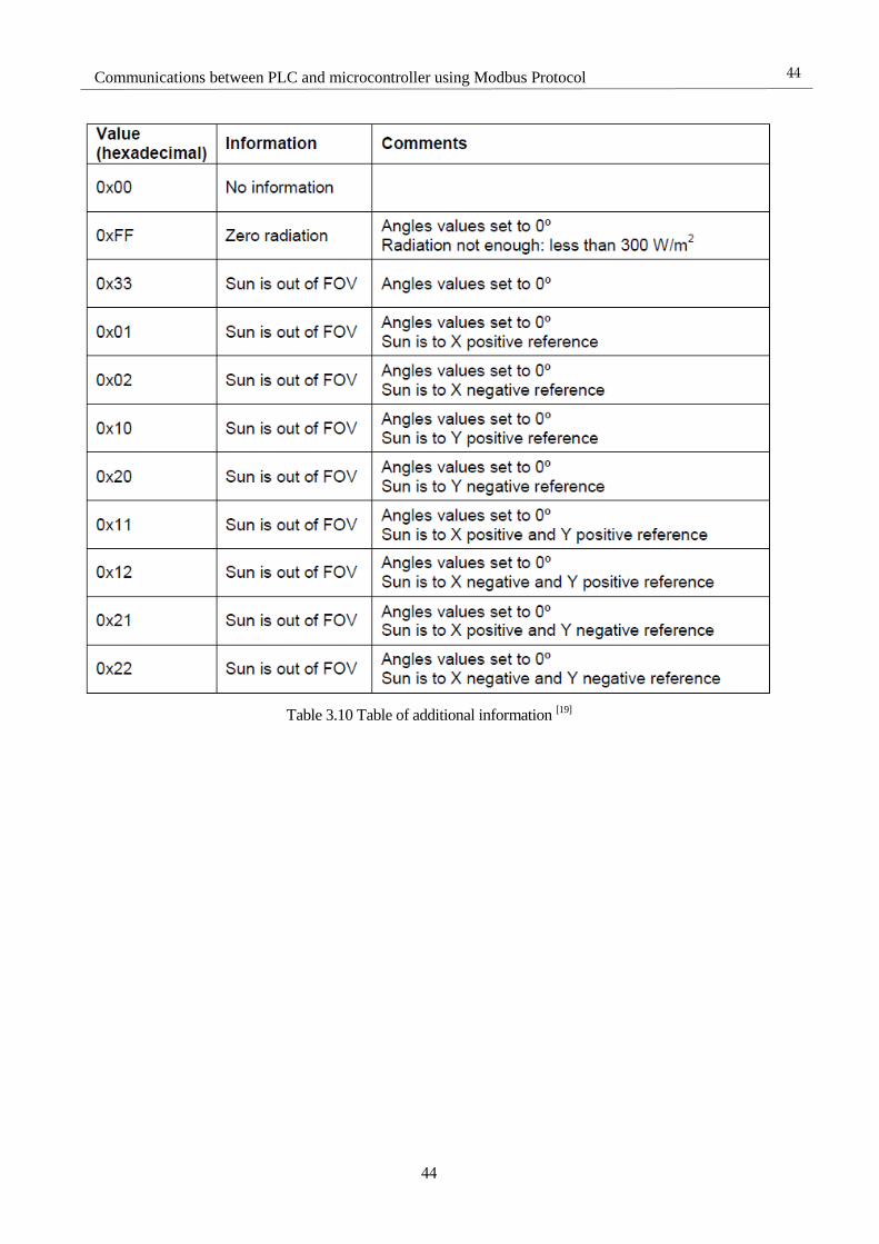
Table 3.10 Table of additional information [19]

3 Modbus devices with Arduino
45
45
3.6.5 Table of MASS-X Modbus registers
Table 3.11 MASS-X Modbus registers
46
Communications between PLC and microcontroller using Modbus Protocol
46
4 M340 MODBUS MASTER
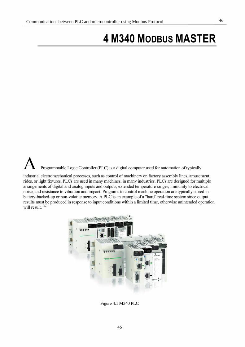
A Programmable Logic Controller (PLC) is a digital computer used for automation of typically
industrial electromechanical processes, such as control of machinery on factory assembly lines, amusement
rides, or light fixtures. PLCs are used in many machines, in many industries. PLCs are designed for multiple
arrangements of digital and analog inputs and outputs, extended temperature ranges, immunity to electrical
noise, and resistance to vibration and impact. Programs to control machine operation are typically stored in
battery-backed-up or non-volatile memory. A PLC is an example of a "hard" real-time system since output
results must be produced in response to input conditions within a limited time, otherwise unintended operation
will result. [22]
Figure 4.1 M340 PLC
4 M340 Modbus MASTER
47
47
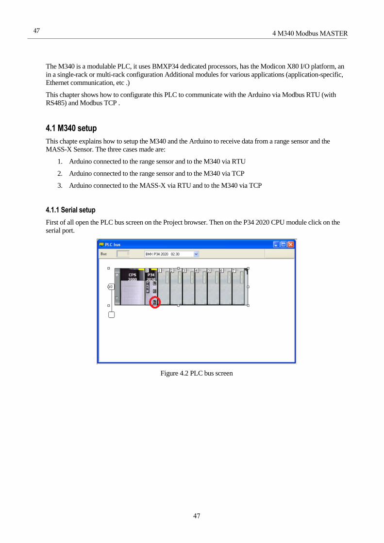
The M340 is a modulable PLC, it uses BMXP34 dedicated processors, has the Modicon X80 I/O platform, an
in a single-rack or multi-rack configuration Additional modules for various applications (application-specific,
Ethernet communication, etc .)
This chapter shows how to configurate this PLC to communicate with the Arduino via Modbus RTU (with
RS485) and Modbus TCP .
4.1 M340 setup
This chapte explains how to setup the M340 and the Arduino to receive data from a range sensor and the
MASS-X Sensor. The three cases made are:
1. Arduino connected to the range sensor and to the M340 via RTU
2. Arduino connected to the range sensor and to the M340 via TCP
3. Arduino connected to the MASS-X via RTU and to the M340 via TCP
4.1.1 Serial setup
First of all open the PLC bus screen on the Project browser. Then on the P34 2020 CPU module click on the
serial port.
Figure 4.2 PLC bus screen

48
Communications between PLC and microcontroller using Modbus Protocol
48
Now on the configuration screen change all the options needed depending on the needs.
Figure 4.3 Serial configuration Screen
Once finished, close this window to accept the changes.
4.1.2 Ethernet setup
First it is needed to create a new connection that I will call ‘Ethernet_1’:
Firgure 4.4 Ethernet communication
Double click on the new communication an then write an IP, the subnet Mask and the IP from the router.
Figure 4.5 Ethernet configuration screen
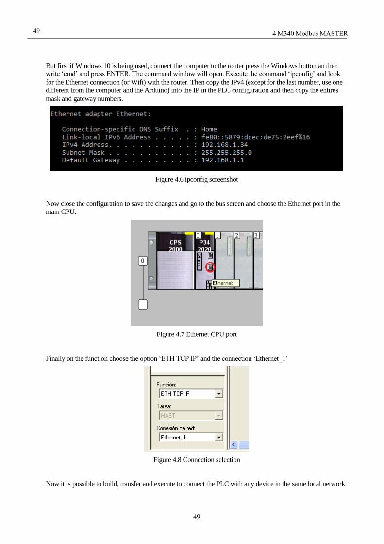
4 M340 Modbus MASTER
49
49
But first if Windows 10 is being used, connect the computer to the router press the Windows button an then
write ‘cmd’ and press ENTER. The command window will open. Execute the command ‘ipconfig’ and look
for the Ethernet connection (or Wifi) with the router. Then copy the IPv4 (except for the last number, use one
different from the computer and the Arduino) into the IP in the PLC configuration and then copy the entires
mask and gateway numbers.
Figure 4.6 ipconfig screenshot
Now close the configuration to save the changes and go to the bus screen and choose the Ethernet port in the
main CPU.
Figure 4.7 Ethernet CPU port
Finally on the function choose the option ‘ETH TCP IP’ and the connection ‘Ethernet_1’
Figure 4.8 Connection selection
Now it is possible to build, transfer and execute to connect the PLC with any device in the same local network.
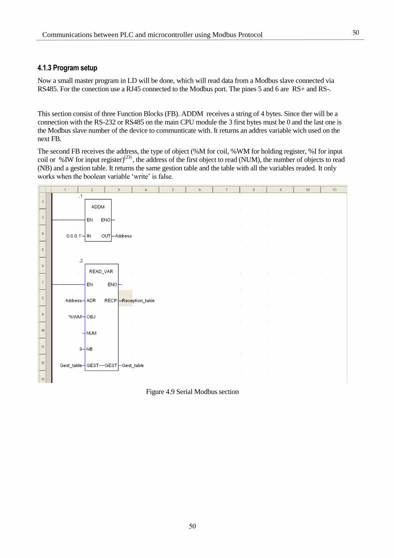
50
Communications between PLC and microcontroller using Modbus Protocol
50
4.1.3 Program setup
Now a small master program in LD will be done, which will read data from a Modbus slave connected via
RS485. For the conection use a RJ45 connected to the Modbus port. The pines 5 and 6 are RS+ and RS-.
This section consist of three Function Blocks (FB). ADDM receives a string of 4 bytes. Since ther will be a
connection with the RS-232 or RS485 on the main CPU module the 3 first bytes must be 0 and the last one is
the Modbus slave number of the device to communticate with. It returns an addres variable wich used on the
next FB.
The second FB receives the address, the type of object (%M for coil, %WM for holding register, %I for input
coil or %IW for input register)[23]
, the address of the first object to read (NUM), the number of objects to read
(NB) and a gestion table. It returns the same gestion table and the table with all the variables readed. It only
works when the boolean variable ‘write’ is false.
Figure 4.9 Serial Modbus section
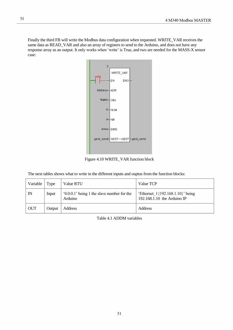
4 M340 Modbus MASTER
51
51
Finally the third FB will write the Modbus data configuration when requested. WRITE_VAR receives the
same data as READ_VAR and also an array of registers to send to the Arduino, and does not have any
response array as an output. It only works when ‘write’ is True, and two are needed for the MASS-X sensor
case:
Figure 4.10 WRITE_VAR function block
The next tables shows what to write in the different inputs and ouptus from the function blocks:
Variable Type Value RTU Value TCP
IN Input ‘0.0.0.1’ being 1 the slave number for the
Arduino
‘Ethernet_1{192.168.1.10}’ being
192.168.1.10 the Arduino IP
OUT Output Address Address
Table 4.1 ADDM variables

52
Communications between PLC and microcontroller using Modbus Protocol
52
Variable Type Value Range sensor RTU Value Range RTU Value MASS-X TCP
ADR Input Address Address Address
OBJ Input ‘%MW’ ‘%MW’ ‘%MW’
NUM Input 0 0 0
NB Input 9 7 24
GEST Input/Output gest gest gest
RECP Output recp recp recp
Table 4.2 READ_VAR variables
Variable Type Value Range RTU Value Range TCP Value MASS-X TCP
ADR Input Address Address Address
OBJ Input ‘%MW’ ‘%MW’ ‘%MW’
NUM Input 0 0 0
NB Input 4 2 2
GEST Input/Output gest_send gest_send1 gest
EMIS Input emis emis1 recp
Table 4.3 WRITE_VAR variables
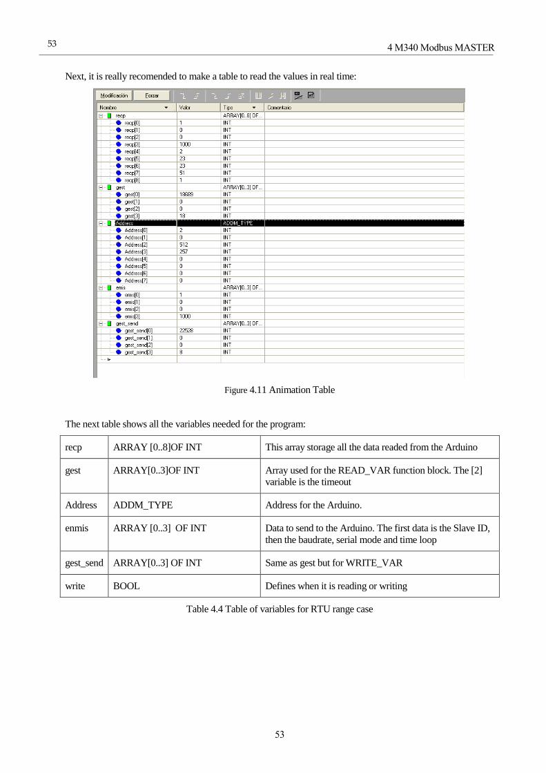
4 M340 Modbus MASTER
53
53
Next, it is really recomended to make a table to read the values in real time:
Figure 4.11 Animation Table
The next table shows all the variables needed for the program:
recp ARRAY [0..8]OF INT This array storage all the data readed from the Arduino
gest ARRAY[0..3]OF INT Array used for the READ_VAR function block. The [2]
variable is the timeout
Address ADDM_TYPE Address for the Arduino.
enmis ARRAY [0..3] OF INT Data to send to the Arduino. The first data is the Slave ID,
then the baudrate, serial mode and time loop
gest_send ARRAY[0..3] OF INT Same as gest but for WRITE_VAR
write BOOL Defines when it is reading or writing
Table 4.4 Table of variables for RTU range case

54
Communications between PLC and microcontroller using Modbus Protocol
54
recp ARRAY [0..6] OF INT This array storage all the data readed from the Arduino
gest ARRAY[0..3]OF INT Array used for the READ_VAR function block. The [2]
variables is the timeout
Address ADDM_TYPE Address for the Arduino.
enmis ARRAY [0..1] OF INT Data to send to the Arduino. The first data is the Slave ID,
then the baudrate, serial mode and time loop
gest_send ARRAY[0..3] OF INT Same as gest but for WRITE_VAR
write BOOL Defines when it is reading or writing
Table 4.5 Table of variables for TCP range case
recp ARRAY [0..6] OF INT This array storage all the data readed from the Arduino
gest ARRAY[0..3]OF INT Array used for the READ_VAR function block. The [2]
variables is the timeout
Address ADDM_TYPE Address for the Arduino.
enmis ARRAY [0..1] OF INT Data to send to the Arduino. The first data is the Slave ID,
then the baudrate, serial mode and time loop
gest_send ARRAY[0..3] OF INT Same as gest but for WRITE_VAR
write BOOL Defines when it is reading or writing
Table 4.6 Table of variables for TCP MASS-X case

4 M340 Modbus MASTER
55
55
Last but not least there is an operator screen for the three cases:
Figure 4.12 Range sensor RTU operator screen
Figure 4.13 Range sensor RTU operator screen

56
Communications between PLC and microcontroller using Modbus Protocol
56
Table 4.7 Range sensor RTU operator screen
We have to link each display to each variable from the recp array (see tables3.5, 3.7 and 3.11). There are also
4 forms to write changes in the Arduino configuration (or 2 for TCP) and a button to summit all the changes.

4 M340 Modbus MASTER
57
57
4.2 Arduino Setup
The Arduino in this chapter has three different sketches depending on the case. This subchapter will explain
the code just for the last case. For the first case (RTU with range sensor), it is possible to copy the code from
chapter 3.4 and for the second case (TCP with range sensor), the code is the same from chapter 3.5
One important thing before looking at the last case code is to be sure to enable the RS485 when declaring the
Modbus object in the first case:
Modbus slave (1, 0, 3);//Slave number 1, port 0 and pin 3 for
RS485 enable pin
4.2.1 The sketch (Variable declaration)
First, declare the libraries. Since ModbusRtu.h is no compatible with Mudbus.h, the library ModbusMaster.h
has to be used, which is no compatible with RS485 unless some changes are done into the .cpp file inside the
library.
#include <Ethernet.h>
#include <SPI.h>
#include <Mudbus.h>
#include <EEPROM.h>
#include <ModbusMaster.h>
Then declare the EEPROM addresses for the Modbus TCP configuration:
//EEPROM addresses
#define IP_ADDR 0
#define LOOP_TIMER_HIGH_ADDR 1
#define LOOP_TIMER_LOW_ADDR 2
Now declare the master object and
// instantiate ModbusMaster object as slave ID 1 and serial port 0
ModbusMaster node(1, 0);
uint8_t result;
Declare the timer variable.
unsigned long Timer;

58
Communications between PLC and microcontroller using Modbus Protocol
58
Now declare the Modbus TCP slave object an all the variables needed to configure it.
Mudbus Mb;
uint8_t ipB = 1;
uint16_t loop_timer = 100;
// Ethernet settings (depending on MAC and Local network)
byte mac[] = {0x90, 0xA2, 0xDA, 0x0E, 0x94, 0xB5 };
byte ip[] = {192, 168, 1, 10};
byte subnet[] = {255, 255, 255, 0};
4.2.2 The sketch (Setup)
First, declare the pin 3 as OUTPUT. This is very important to adapt the library for RS485 use.
pinMode(3, OUTPUT);
Now start the Master:
node.begin(19200);
Finally configure the IP and the timer from the EEPROM and start the Ethernet interface.
//-----Setup Modbus Conf-----//
//configure and start communications
//ip[3] = EEPROM.read(IP_ADDR);
if (ip[3] == 0) {
ip[3] = 10;
EEPROM.write(IP_ADDR, ip[3]);
}
Mb.R[0] = ip[3];
Ethernet.begin(mac, ip, subnet); // start etehrnet interface
//configure loop timer
loop_timer = (uint16_t)EEPROM.read(LOOP_TIMER_HIGH_ADDR);
loop_timer = loop_timer << 8;
loop_timer |= (uint16_t)EEPROM.read(LOOP_TIMER_LOW_ADDR);
4 M340 Modbus MASTER
59
59
if (loop_timer == 0) {
loop_timer = 100;
EEPROM.write(LOOP_TIMER_LOW_ADDR, loop_timer);
EEPROM.write(LOOP_TIMER_HIGH_ADDR, loop_timer >> 8);
}
loop_timer << 8;
Mb.R[1] = loop_timer;
Timer = millis();
4.2.3 The sketch (Loop)
Run the Modbus slave.
Mb.Run();
Read data from the MASS-X sensor using the function readHoldingRegisters from the ModbusMaster library.
The 1 is the address for the first register to read in the sensor and 22 is the number of registers to read. If the
reading was a success then call the reg_poll function:
if ((millis() - Timer > loop_timer) | (millis() - Timer < 0)) {
//poll messages
result = node.readHoldingRegisters(1, 22);
if (result == node.ku8MBSuccess) {
reg_poll();
}
Timer = millis();
}
4.2.4 The sketch (Loop)
First put all the data read from the Master into the Slave registers. Since the first two registers are the Modbus
configuration registers for the slave, it is possible to write at the register [2]:
int i;
for (i = 0; i < 22; i++) {
Mb.R[i + 2] = node.getResponseBuffer(i);
}

60
Communications between PLC and microcontroller using Modbus Protocol
60
Finally update the configuration register as done in chapter 3.5:
if (ip[3] != Mb.R[0]) {
ip[3] = Mb.R[0];
EEPROM.write(IP_ADDR, ip[3]);
Ethernet.begin(mac, ip, subnet);
}
if (loop_timer != Mb.R[1]) {
loop_timer = Mb.R[1];
EEPROM.write(LOOP_TIMER_LOW_ADDR, loop_timer);
EEPROM.write(LOOP_TIMER_HIGH_ADDR, loop_timer >> 8);
loop_timer << 8;
}
4.3 ModbusMaster.h configuration for RS485
Before importing the library .zip, on ModbusMaster.cpp library somewhere at 760th line, add
digitalWrite(3, HIGH); and digitalWrite(3, LOW); lines:
// flush receive buffer before transmitting request
while (MBSerial->read() != -1);
// transmit request
digitalWrite(3, HIGH); //RS485 pin
for (i = 0; i < u8ModbusADUSize; i++)
{
#if defined(ARDUINO) && ARDUINO >= 100
MBSerial->write(u8ModbusADU[i]);
#else
MBSerial->print(u8ModbusADU[i], BYTE);
#endif
}
u8ModbusADUSize = 0;
MBSerial->flush(); // flush transmit buffer
digitalWrite(3, LOW); //RS485 pin
// loop until we run out of time or bytes, or an error occurs
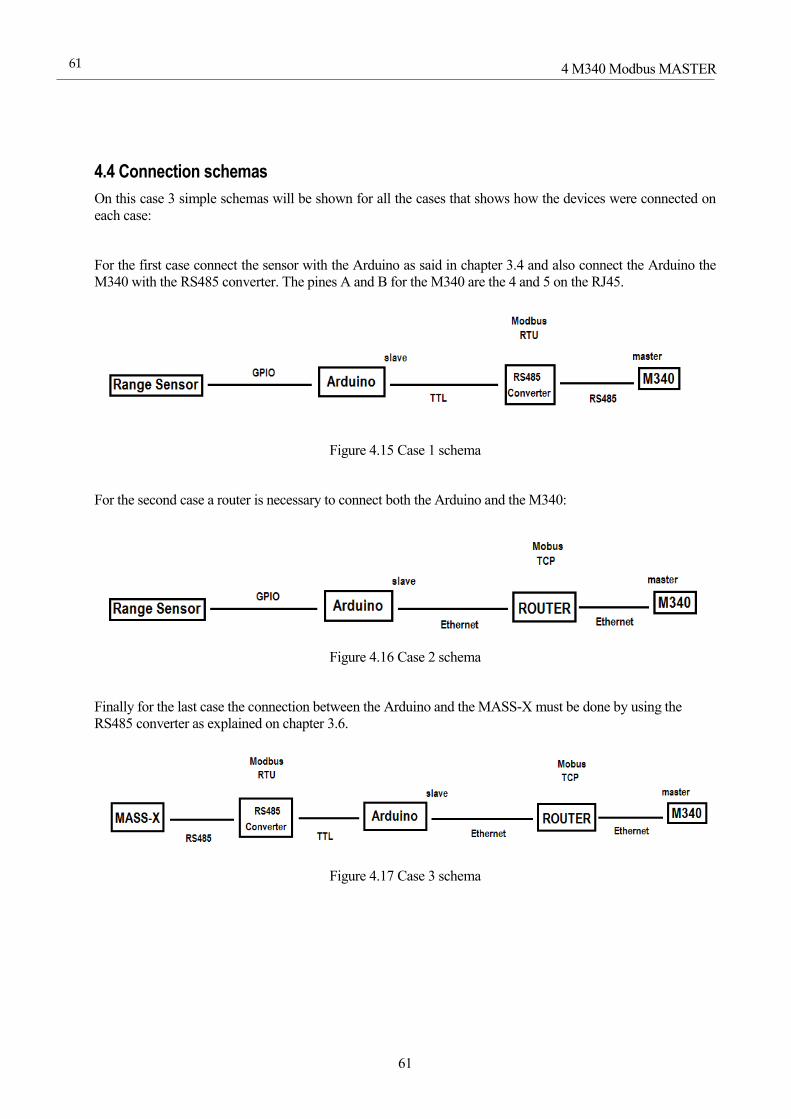
4 M340 Modbus MASTER
61
61
4.4 Connection schemas
On this case 3 simple schemas will be shown for all the cases that shows how the devices were connected on
each case:
For the first case connect the sensor with the Arduino as said in chapter 3.4 and also connect the Arduino the
M340 with the RS485 converter. The pines A and B for the M340 are the 4 and 5 on the RJ45.
Figure 4.15 Case 1 schema
For the second case a router is necessary to connect both the Arduino and the M340:
Figure 4.16 Case 2 schema
Finally for the last case the connection between the Arduino and the MASS-X must be done by using the
RS485 converter as explained on chapter 3.6.
Figure 4.17 Case 3 schema
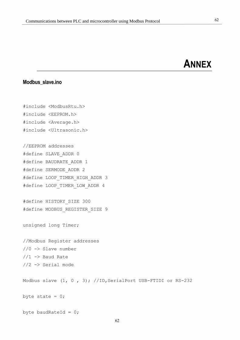
62
Communications between PLC and microcontroller using Modbus Protocol
62
ANNEX
Modbus_slave.ino
#include <ModbusRtu.h>
#include <EEPROM.h>
#include <Average.h>
#include <Ultrasonic.h>
//EEPROM addresses
#define SLAVE_ADDR 0
#define BAUDRATE_ADDR 1
#define SERMODE_ADDR 2
#define LOOP_TIMER_HIGH_ADDR 3
#define LOOP_TIMER_LOW_ADDR 4
#define HISTORY_SIZE 300
#define MODBUS_REGISTER_SIZE 9
unsigned long Timer;
//Modbus Register addresses
//0 -> Slave number
//1 -> Baud Rate
//2 -> Serial mode
Modbus slave (1, 0 , 3); //ID,SerialPort USB-FTIDI or RS-232
byte state = 0;
byte baudRateId = 0;
Annex
63
63
byte serModeId = 0;
uint16_t loop_timer = 100;
uint16_t measure;
uint16_t au16data[MODBUS_REGISTER_SIZE];
Average<uint16_t> history(HISTORY_SIZE);
Ultrasonic ultrasonic(22,24); // (Trig PIN,Echo PIN)
void setup() {
//-----Setup Modbus Conf-----//
//Setup Slave number
slave.setID(EEPROM.read(SLAVE_ADDR));
if (slave.getID() == 0) {
EEPROM.write(SLAVE_ADDR, 1);
slave.setID(1);
}
au16data[0] = uint16_t(slave.getID());
//configure and start communications
baudRateId = EEPROM.read(BAUDRATE_ADDR);
serModeId = EEPROM.read(SERMODE_ADDR);
au16data[1] = uint16_t(baudRateId);
au16data[2] = uint16_t(serModeId);
beginSerial(baudRateId, serModeId);
//configure loop timer
loop_timer = (uint16_t)EEPROM.read(LOOP_TIMER_HIGH_ADDR);
loop_timer = loop_timer << 8;
loop_timer |= (uint16_t)EEPROM.read(LOOP_TIMER_LOW_ADDR);
if (loop_timer == 0) {
loop_timer = 100;
EEPROM.write(LOOP_TIMER_LOW_ADDR, loop_timer);
64
Communications between PLC and microcontroller using Modbus Protocol
64
EEPROM.write(LOOP_TIMER_HIGH_ADDR, loop_timer >> 8);
}
loop_timer << 8;
au16data[3] = loop_timer;
Timer = millis();
}
void loop() {
state = slave.poll(au16data, MODBUS_REGISTER_SIZE);
if ((millis() - Timer > loop_timer) | (millis() - Timer < 0)) {
//poll messages
reg_poll();
Timer = millis();
}
}
void reg_poll() {
//measure = ultrasonic.Ranging(CM);
measure = random(0,300);
history.rolling(measure);
au16data[4] = uint16_t(measure);
au16data[5] = history.mean();
au16data[6] = history.stddev();
au16data[7] = history.maximum();
au16data[8] = history.minimum();
if (uint16_t(slave.getID()) != au16data[0]) {
slave.setID(uint8_t(au16data[0]));
EEPROM.update(SLAVE_ADDR, byte(au16data[0]));
}
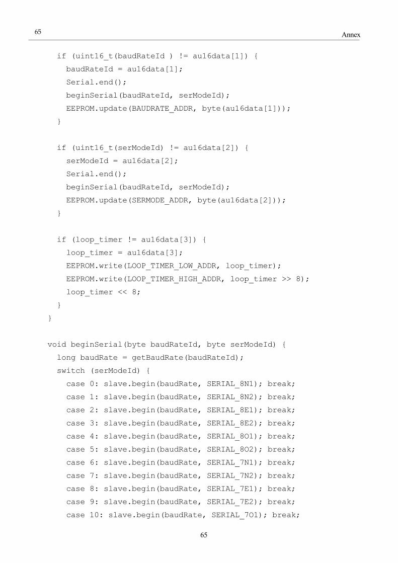
Annex
65
65
if (uint16_t(baudRateId ) != au16data[1]) {
baudRateId = au16data[1];
Serial.end();
beginSerial(baudRateId, serModeId);
EEPROM.update(BAUDRATE_ADDR, byte(au16data[1]));
}
if (uint16_t(serModeId) != au16data[2]) {
serModeId = au16data[2];
Serial.end();
beginSerial(baudRateId, serModeId);
EEPROM.update(SERMODE_ADDR, byte(au16data[2]));
}
if (loop_timer != au16data[3]) {
loop_timer = au16data[3];
EEPROM.write(LOOP_TIMER_LOW_ADDR, loop_timer);
EEPROM.write(LOOP_TIMER_HIGH_ADDR, loop_timer >> 8);
loop_timer << 8;
}
}
void beginSerial(byte baudRateId, byte serModeId) {
long baudRate = getBaudRate(baudRateId);
switch (serModeId) {
case 0: slave.begin(baudRate, SERIAL_8N1); break;
case 1: slave.begin(baudRate, SERIAL_8N2); break;
case 2: slave.begin(baudRate, SERIAL_8E1); break;
case 3: slave.begin(baudRate, SERIAL_8E2); break;
case 4: slave.begin(baudRate, SERIAL_8O1); break;
case 5: slave.begin(baudRate, SERIAL_8O2); break;
case 6: slave.begin(baudRate, SERIAL_7N1); break;
case 7: slave.begin(baudRate, SERIAL_7N2); break;
case 8: slave.begin(baudRate, SERIAL_7E1); break;
case 9: slave.begin(baudRate, SERIAL_7E2); break;
case 10: slave.begin(baudRate, SERIAL_7O1); break;
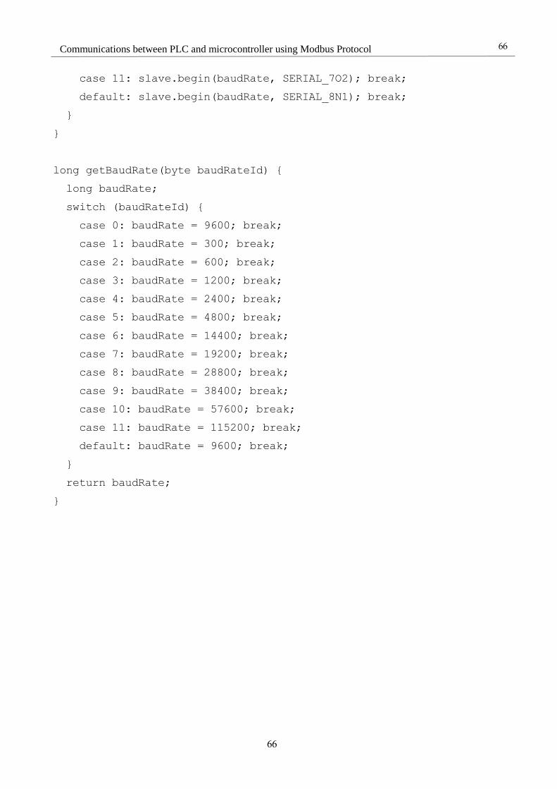
66
Communications between PLC and microcontroller using Modbus Protocol
66
case 11: slave.begin(baudRate, SERIAL_7O2); break;
default: slave.begin(baudRate, SERIAL_8N1); break;
}
}
long getBaudRate(byte baudRateId) {
long baudRate;
switch (baudRateId) {
case 0: baudRate = 9600; break;
case 1: baudRate = 300; break;
case 2: baudRate = 600; break;
case 3: baudRate = 1200; break;
case 4: baudRate = 2400; break;
case 5: baudRate = 4800; break;
case 6: baudRate = 14400; break;
case 7: baudRate = 19200; break;
case 8: baudRate = 28800; break;
case 9: baudRate = 38400; break;
case 10: baudRate = 57600; break;
case 11: baudRate = 115200; break;
default: baudRate = 9600; break;
}
return baudRate;
}
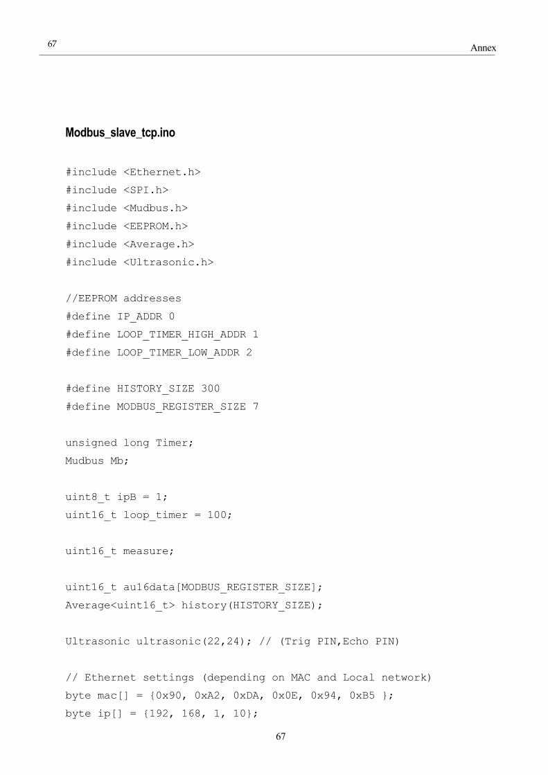
Annex
67
67
Modbus_slave_tcp.ino
#include <Ethernet.h>
#include <SPI.h>
#include <Mudbus.h>
#include <EEPROM.h>
#include <Average.h>
#include <Ultrasonic.h>
//EEPROM addresses
#define IP_ADDR 0
#define LOOP_TIMER_HIGH_ADDR 1
#define LOOP_TIMER_LOW_ADDR 2
#define HISTORY_SIZE 300
#define MODBUS_REGISTER_SIZE 7
unsigned long Timer;
Mudbus Mb;
uint8_t ipB = 1;
uint16_t loop_timer = 100;
uint16_t measure;
uint16_t au16data[MODBUS_REGISTER_SIZE];
Average<uint16_t> history(HISTORY_SIZE);
Ultrasonic ultrasonic(22,24); // (Trig PIN,Echo PIN)
// Ethernet settings (depending on MAC and Local network)
byte mac[] = {0x90, 0xA2, 0xDA, 0x0E, 0x94, 0xB5 };
byte ip[] = {192, 168, 1, 10};
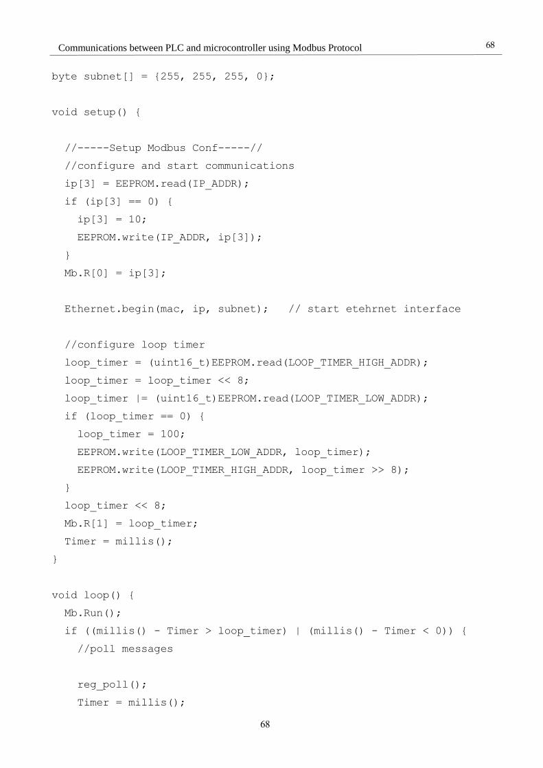
68
Communications between PLC and microcontroller using Modbus Protocol
68
byte subnet[] = {255, 255, 255, 0};
void setup() {
//-----Setup Modbus Conf-----//
//configure and start communications
ip[3] = EEPROM.read(IP_ADDR);
if (ip[3] == 0) {
ip[3] = 10;
EEPROM.write(IP_ADDR, ip[3]);
}
Mb.R[0] = ip[3];
Ethernet.begin(mac, ip, subnet); // start etehrnet interface
//configure loop timer
loop_timer = (uint16_t)EEPROM.read(LOOP_TIMER_HIGH_ADDR);
loop_timer = loop_timer << 8;
loop_timer |= (uint16_t)EEPROM.read(LOOP_TIMER_LOW_ADDR);
if (loop_timer == 0) {
loop_timer = 100;
EEPROM.write(LOOP_TIMER_LOW_ADDR, loop_timer);
EEPROM.write(LOOP_TIMER_HIGH_ADDR, loop_timer >> 8);
}
loop_timer << 8;
Mb.R[1] = loop_timer;
Timer = millis();
}
void loop() {
Mb.Run();
if ((millis() - Timer > loop_timer) | (millis() - Timer < 0)) {
//poll messages
reg_poll();
Timer = millis();
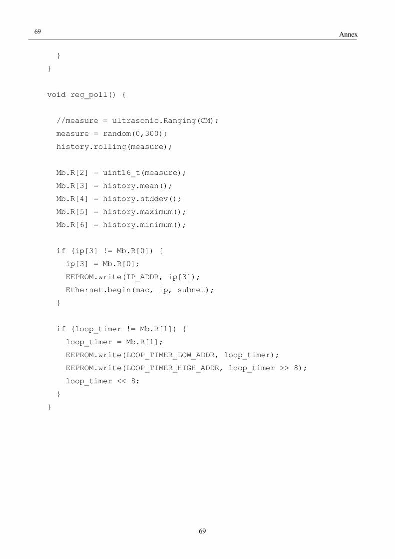
Annex
69
69
}
}
void reg_poll() {
//measure = ultrasonic.Ranging(CM);
measure = random(0,300);
history.rolling(measure);
Mb.R[2] = uint16_t(measure);
Mb.R[3] = history.mean();
Mb.R[4] = history.stddev();
Mb.R[5] = history.maximum();
Mb.R[6] = history.minimum();
if (ip[3] != Mb.R[0]) {
ip[3] = Mb.R[0];
EEPROM.write(IP_ADDR, ip[3]);
Ethernet.begin(mac, ip, subnet);
}
if (loop_timer != Mb.R[1]) {
loop_timer = Mb.R[1];
EEPROM.write(LOOP_TIMER_LOW_ADDR, loop_timer);
EEPROM.write(LOOP_TIMER_HIGH_ADDR, loop_timer >> 8);
loop_timer << 8;
}
}

70
Communications between PLC and microcontroller using Modbus Protocol
70
Modbus_master.ino
#include <ModbusRtu.h>
#include <Wire.h>
#include <LiquidCrystal_I2C.h>
/*-----( Declare Constants and Pin Numbers )-----*/
#define SSerialTxControl 3 //RS485 Direction control
uint16_t au16data[22]; //!< data array for modbus network sharing
uint8_t u8state; //!< machine state
uint8_t u8query; //!< pointer to message query
LiquidCrystal_I2C lcd(0x27, 16, 2);
/**
Modbus object declaration
u8id : node id = 0 for master, = 1..247 for slave
u8serno : serial port (use 0 for Serial)
u8txenpin : 0 for RS-232 and USB-FTDI
or any pin number > 1 for RS-485
*/
Modbus master(0, 0, 3); // this is master for RS-485
/**
This is an structe which contains a query to an slave device
*/
modbus_t telegram;
unsigned long u32wait; // timer for the modbus

Annex
71
71
void setup() {
// telegram 0: read registers
telegram.u8id = 1; // slave address
telegram.u8fct = 3; // function code (this one is registers
read)
telegram.u16RegAdd = 0; // start address in slave
telegram.u16CoilsNo = 22; // number of elements (coils or
registers) to read
telegram.au16reg = au16data; // pointer to a memory array in the
Arduino
master.begin( 19200, SERIAL_8N1 ); // baud-rate at 19200
master.setTimeOut( 5000 ); // if there is no answer in 5000 ms,
roll over
u32wait = millis() + 1000;
u8state = u8query = 0;
lcd.begin(); //initialize the lcd
lcd.backlight(); //open the backlight
}
void loop() {
switch ( u8state ) {
case 0:
if (millis() > u32wait) u8state++; // wait state
break;
case 1:
master.query( telegram ); // send query (only once)
u8state++;
break;
case 2:
master.poll(); // check incoming messages
if (master.getState() == COM_IDLE) {
u8state ++;
u32wait = millis() + 1000;}
break;

72
Communications between PLC and microcontroller using Modbus Protocol
72
case 3:
u8state = 0;
lcd.setCursor(0, 0);
lcd.print("FOV: ");
lcd.print(au16data[1]);
lcd.setCursor(0, 1);
lcd.print("A Info: ");
lcd.print(au16data[7]);
delay(3000);
lcd.clear();
lcd.setCursor(0, 0);
lcd.print("DNI R: ");
lcd.print(au16data[8]);
lcd.setCursor(0, 1);
lcd.print("T: ");
lcd.print(au16data[9]);
delay(3000);
lcd.clear();
lcd.setCursor(0, 0);
lcd.print("FAX: ");
lcd.print(au16data[10]);
lcd.setCursor(0, 1);
lcd.print("FAY: ");
lcd.print(au16data[11]);
delay(3000);
lcd.clear();
lcd.setCursor(0, 0);
lcd.print("AX: ");
lcd.print(au16data[12]);
lcd.setCursor(0, 1);
lcd.print("AY: ");
lcd.print(au16data[13]);

Annex
73
73
delay(3000);
lcd.clear();
lcd.setCursor(0, 0);
lcd.print("Azi: ");
lcd.print(au16data[14]);
lcd.setCursor(0, 1);
lcd.print("Ele: ");
lcd.print(au16data[15]);
delay(3000);
lcd.clear();
lcd.setCursor(0, 0);
lcd.print("MVX: ");
lcd.print(au16data[16]);
lcd.setCursor(0, 1);
lcd.print("MVY: ");
lcd.print(au16data[17]);
delay(3000);
lcd.clear();
lcd.setCursor(0, 0);
lcd.print("MVZ: ");
lcd.print(au16data[18]);
delay(2000);
lcd.clear();
lcd.setCursor(0, 0);
lcd.print("AVX: ");
lcd.print(au16data[19]);
lcd.setCursor(0, 1);
lcd.print("AVY: ");
lcd.print(au16data[20]);
delay(3000);
lcd.clear();

74
Communications between PLC and microcontroller using Modbus Protocol
74
lcd.setCursor(0, 0);
lcd.print("AVZ: ");
lcd.print(au16data[21]);
delay(2000);
lcd.clear();
break;
}
}
Restart_EEPROM.ino
This program can be used to set the first byte of the EEPROM to 1 and the rest to 0.
#include <EEPROM.h>
void setup() {
// put your setup code here, to run once:
EEPROM.write(0,1);
for (int i = 1 ; i < EEPROM.length() ; i++) {
EEPROM.write(i, 0);
}
}
void loop() {
// put your main code here, to run repeatedly:
}
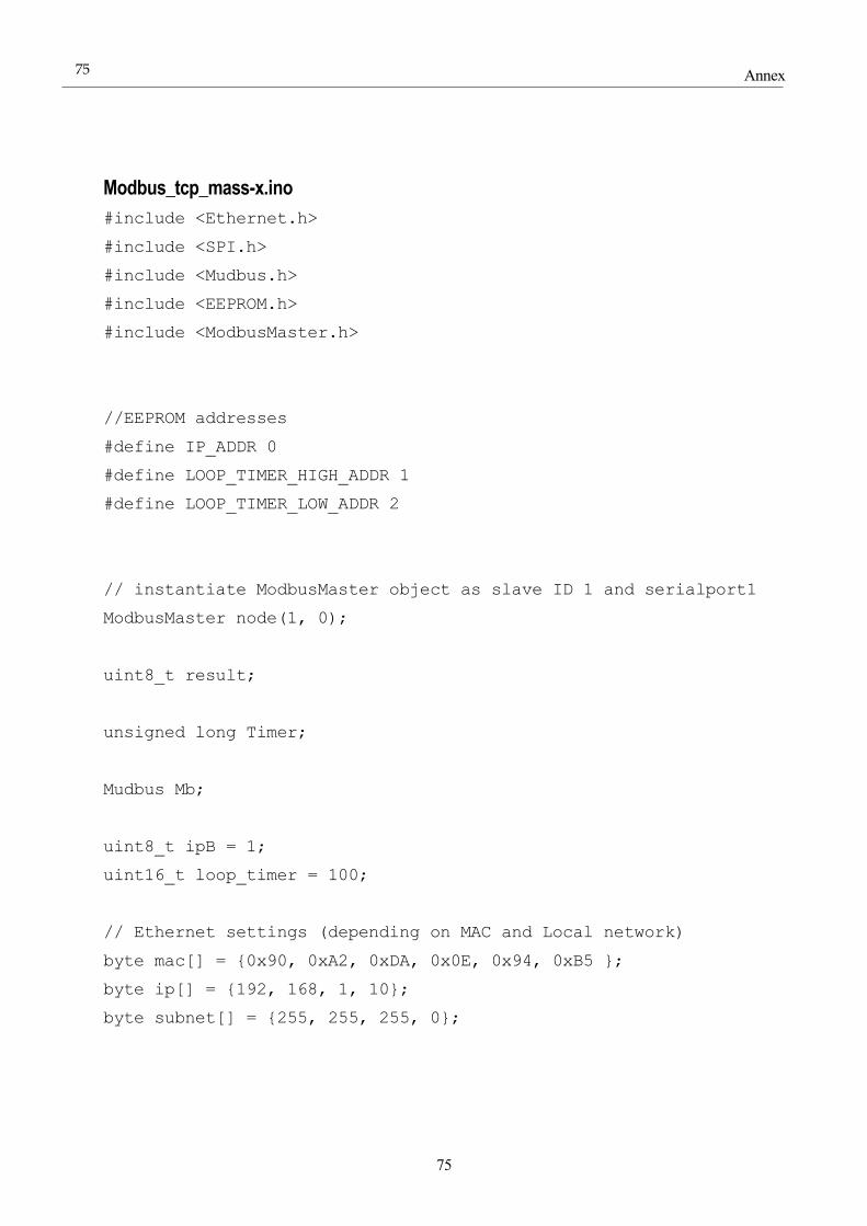
Annex
75
75
Modbus_tcp_mass-x.ino
#include <Ethernet.h>
#include <SPI.h>
#include <Mudbus.h>
#include <EEPROM.h>
#include <ModbusMaster.h>
//EEPROM addresses
#define IP_ADDR 0
#define LOOP_TIMER_HIGH_ADDR 1
#define LOOP_TIMER_LOW_ADDR 2
// instantiate ModbusMaster object as slave ID 1 and serialport1
ModbusMaster node(1, 0);
uint8_t result;
unsigned long Timer;
Mudbus Mb;
uint8_t ipB = 1;
uint16_t loop_timer = 100;
// Ethernet settings (depending on MAC and Local network)
byte mac[] = {0x90, 0xA2, 0xDA, 0x0E, 0x94, 0xB5 };
byte ip[] = {192, 168, 1, 10};
byte subnet[] = {255, 255, 255, 0};
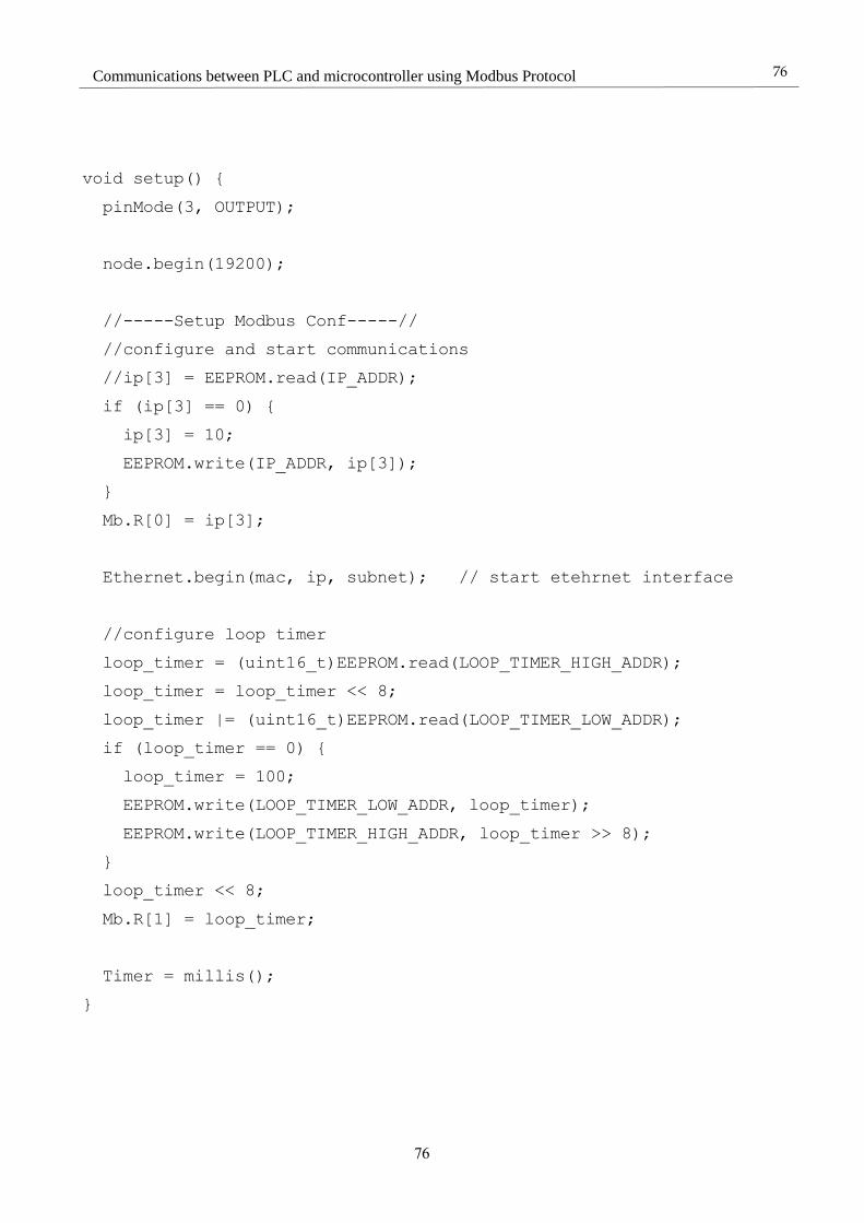
76
Communications between PLC and microcontroller using Modbus Protocol
76
void setup() {
pinMode(3, OUTPUT);
node.begin(19200);
//-----Setup Modbus Conf-----//
//configure and start communications
//ip[3] = EEPROM.read(IP_ADDR);
if (ip[3] == 0) {
ip[3] = 10;
EEPROM.write(IP_ADDR, ip[3]);
}
Mb.R[0] = ip[3];
Ethernet.begin(mac, ip, subnet); // start etehrnet interface
//configure loop timer
loop_timer = (uint16_t)EEPROM.read(LOOP_TIMER_HIGH_ADDR);
loop_timer = loop_timer << 8;
loop_timer |= (uint16_t)EEPROM.read(LOOP_TIMER_LOW_ADDR);
if (loop_timer == 0) {
loop_timer = 100;
EEPROM.write(LOOP_TIMER_LOW_ADDR, loop_timer);
EEPROM.write(LOOP_TIMER_HIGH_ADDR, loop_timer >> 8);
}
loop_timer << 8;
Mb.R[1] = loop_timer;
Timer = millis();
}
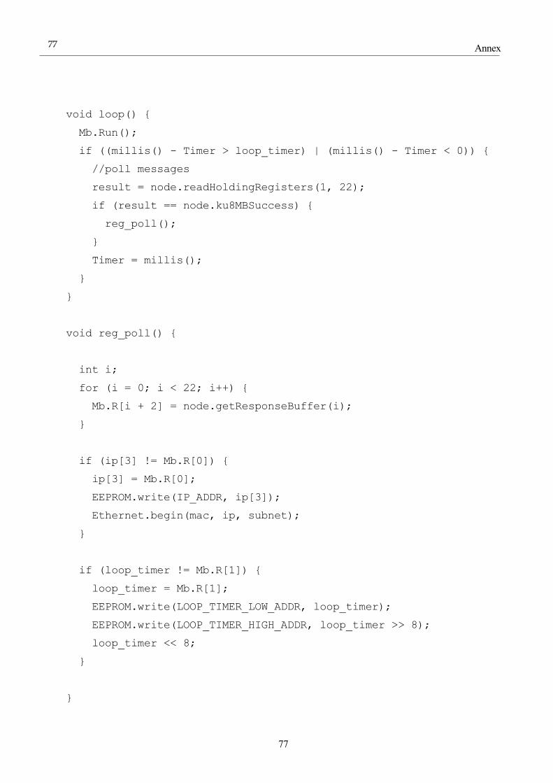
Annex
77
77
void loop() {
Mb.Run();
if ((millis() - Timer > loop_timer) | (millis() - Timer < 0)) {
//poll messages
result = node.readHoldingRegisters(1, 22);
if (result == node.ku8MBSuccess) {
reg_poll();
}
Timer = millis();
}
}
void reg_poll() {
int i;
for (i = 0; i < 22; i++) {
Mb.R[i + 2] = node.getResponseBuffer(i);
}
if (ip[3] != Mb.R[0]) {
ip[3] = Mb.R[0];
EEPROM.write(IP_ADDR, ip[3]);
Ethernet.begin(mac, ip, subnet);
}
if (loop_timer != Mb.R[1]) {
loop_timer = Mb.R[1];
EEPROM.write(LOOP_TIMER_LOW_ADDR, loop_timer);
EEPROM.write(LOOP_TIMER_HIGH_ADDR, loop_timer >> 8);
loop_timer << 8;
}
}

78
Communications between PLC and microcontroller using Modbus Protocol
78
REFERENCES
[1] Modbus organization, “MODBUS APPLICATION PROTOCOL SPECIFICATION V1.1b3”, 2012.
[2] Jon Carson, https://www.dmcinfo.com/latest-thinking/blog/articletype/articleview/articleid/71/remote-
machine-monitoringconnecting-to-a-Modbus-network-with-java-and-jamod, www.DMCinfo.com, 2009
[3]Modbus organization,
http://www.Modbus.org/docs/Modbus_Messaging_Implementation_Guide_V1_0b.pdf, 2006
[4] https://en.wikipedia.org/wiki/Modbus
[5] https://www.arduino.cc/en/Main/ArduinoBoardMega2560
[6] https://www.arduino.cc/en/Main/Software
[7] https://www.arduino.cc/en/Reference/Libraries
[8] https://www.arduino.cc/en/Reference/EEPROM
[9] http://playground.arduino.cc/Main/Average
[10] https://github.com/JRodrigoTech/Ultrasonic-HC-
SR04/commit/c25b1348975f96748b484c3e17f27ab1e34c3ff6
[11] https://github.com/smarmengol/Modbus-Master-Slave-for-Arduino/blob/master/README.md
[12] https://github.com/smarmengol/Modbus-Master-Slave-for-Arduino/blob/master/ModbusRtu.h
[13] https://www.arduino.cc/en/Reference/Ethernet
[14] https://www.arduino.cc/en/Guide/ArduinoEthernetShield
[15] http://en.radzio.dxp.pl/Modbus-master-simulator/
[16] https://github.com/fdebrabander/Arduino-LiquidCrystal-I2C-library
[17] http://ingventor.blogspot.com.es/2016/01/tutorial-arduino-conectar-lcd-162-por.html
[18] http://arduino.ru/forum/programmirovanie/arduino-mega-2560-i-rs485
[19] MASS-X Datasheet
[20] https://arduino-info.wikispaces.com/SoftwareSerialRS485Example
[21]http://www.guilleviniag.com/downloads/Products/Schneider/M340/Manuals/M340%20Serial%20Link%2
0Manual.pdf
[22] https://en.wikipedia.org/wiki/Programmable_logic_controller
[23] http://www2.schneider-
electric.com/resources/sites/SCHNEIDER_ELECTRIC/content/live/FAQS/142000/FA142330/es_ES/Unity%
20-%20M340%20Enlace%20Serie.pdf
[24] https://github.com/4-20ma/ModbusMaster/issues/33