tr-2010-03 travel to devil’s lake, nd to observe planned ... · 4. synopsis of trip: tony wahl...
TRANSCRIPT

U.S. Department of the Interior Bureau of Reclamation Technical Service Center Hydraulic Investigations and Laboratory Services Group Denver, Colorado September 2010
TR-2010-03
Travel to Devil’s Lake, ND to Observe Planned Levee Breach Dates of travel: August 29-September 1, 2010

BUREAU OF RECLAMATION Technical Service Center Denver, Colorado TRAVEL REPORT Code : 86-68460 Date: September 21, 2010 To : Manager, Hydraulic Investigations and Laboratory Services Group From : Tony Wahl and Dale Lentz Subject: Travel to Devils Lake, ND to observe planned levee breach 1. Travel period: August 29-September 1, 2010 2. Places or offices visited: Devils Lake, ND 3. Purpose of trip: To collect data to support a case study analysis of the controlled breaching of the Kurtz Dike on Devils Lake. 3a. Background: Devils Lake is the largest freshwater lake in North Dakota and is located in a closed basin with no natural outlet at its present water level. The lake is prone to large water level fluctuations over long time periods and has risen approximately 30 ft since 1993 to historic high levels exceeding previous historic highs in the 1870s. An additional 6 ft of water level rise is needed to reach the natural outlet to the Sheyenne River, tributary to the Red River which flows north into Canada. The lake is believed to have last reached this level about 1000 years ago. As the lake has risen in recent years, dikes and levees have been constructed to protect homes, farmland and infrastructure, and many existing roadway embankments are also now functioning as dams. The Kurtz Dike was constructed in the late 1990s. The history of its construction is poorly documented. The embankment may have initially been constructed to create a stock pond, and was then enlarged as the lake level increased, although no one on site was able to say for certain who performed the majority of the construction work. Also, the dike crest may have been raised again very recently to allow time for construction of highway improvements in areas protected by the dike. Presently the embankment is about 8 ft high and the lake level is about 1 ft below the crest of the embankment. A decision has been made to now breach the dike and allow expansion of Devils Lake and the inundation of about 200 acres of low-lying land beyond the dike. The expected drop in the level of Devils Lake due to the breach is negligible. We learned of the planned breach on August 23 and decided to take the opportunity to make erodibility measurements on the dike prior to the planned breach and to monitor the breaching process for potential analysis as an embankment dam failure case study.
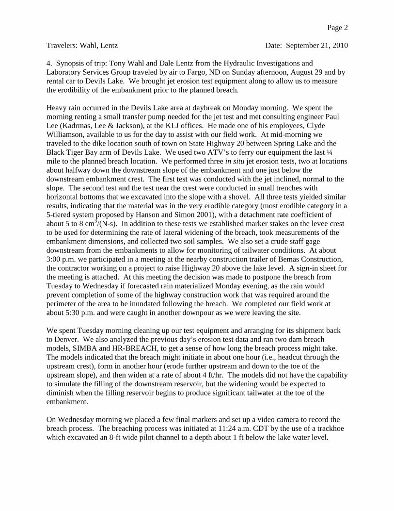
Page 2 Travelers: Wahl, Lentz Date: September 21, 2010 4. Synopsis of trip: Tony Wahl and Dale Lentz from the Hydraulic Investigations and Laboratory Services Group traveled by air to Fargo, ND on Sunday afternoon, August 29 and by rental car to Devils Lake. We brought jet erosion test equipment along to allow us to measure the erodibility of the embankment prior to the planned breach. Heavy rain occurred in the Devils Lake area at daybreak on Monday morning. We spent the morning renting a small transfer pump needed for the jet test and met consulting engineer Paul Lee (Kadrmas, Lee & Jackson), at the KLJ offices. He made one of his employees, Clyde Williamson, available to us for the day to assist with our field work. At mid-morning we traveled to the dike location south of town on State Highway 20 between Spring Lake and the Black Tiger Bay arm of Devils Lake. We used two ATV’s to ferry our equipment the last ¼ mile to the planned breach location. We performed three in situ jet erosion tests, two at locations about halfway down the downstream slope of the embankment and one just below the downstream embankment crest. The first test was conducted with the jet inclined, normal to the slope. The second test and the test near the crest were conducted in small trenches with horizontal bottoms that we excavated into the slope with a shovel. All three tests yielded similar results, indicating that the material was in the very erodible category (most erodible category in a 5-tiered system proposed by Hanson and Simon 2001), with a detachment rate coefficient of about 5 to 8 cm3/(N-s). In addition to these tests we established marker stakes on the levee crest to be used for determining the rate of lateral widening of the breach, took measurements of the embankment dimensions, and collected two soil samples. We also set a crude staff gage downstream from the embankments to allow for monitoring of tailwater conditions. At about 3:00 p.m. we participated in a meeting at the nearby construction trailer of Bemas Construction, the contractor working on a project to raise Highway 20 above the lake level. A sign-in sheet for the meeting is attached. At this meeting the decision was made to postpone the breach from Tuesday to Wednesday if forecasted rain materialized Monday evening, as the rain would prevent completion of some of the highway construction work that was required around the perimeter of the area to be inundated following the breach. We completed our field work at about 5:30 p.m. and were caught in another downpour as we were leaving the site. We spent Tuesday morning cleaning up our test equipment and arranging for its shipment back to Denver. We also analyzed the previous day’s erosion test data and ran two dam breach models, SIMBA and HR-BREACH, to get a sense of how long the breach process might take. The models indicated that the breach might initiate in about one hour (i.e., headcut through the upstream crest), form in another hour (erode further upstream and down to the toe of the upstream slope), and then widen at a rate of about 4 ft/hr. The models did not have the capability to simulate the filling of the downstream reservoir, but the widening would be expected to diminish when the filling reservoir begins to produce significant tailwater at the toe of the embankment. On Wednesday morning we placed a few final markers and set up a video camera to record the breach process. The breaching process was initiated at 11:24 a.m. CDT by the use of a trackhoe which excavated an 8-ft wide pilot channel to a depth about 1 ft below the lake water level.

Page 3 Travelers: Wahl, Lentz Date: September 21, 2010
Figure 1. — Jet test underway near downstream toe of embankment. The water surface in the distance is approximately 12 ft lower than the water level on the upstream side of the embankment.
Figure 2. — Scour hole eroded into embankment following completion of the jet test performed on the embankment slope. Approximately 3 inches of surface material was removed prior to performing the test.

Page 4 Travelers: Wahl, Lentz Date: September 21, 2010 For the first 20-30 minutes the breach developed as expected and at a rate that appeared reasonable based on our modeling. A gully and stair-stepped headcuts quickly formed on the downstream face. The headcut at the downstream toe advanced most rapidly and began to overtake the upstream headcuts, causing the overall slope of the developing channel to steepen. However, in the next 15 minutes the erosion behavior changed. The toe stabilized and the slope began to flatten again, eventually exposing a core of much more resistant material that was apparently an original embankment section that had subsequently been covered by more erodible materials. This section of the embankment proved to be extremely erosion resistant. This material in this section appeared through the flowing water to be different in color and makeup, as it contained a small fraction of large gravel and cobble pieces which had not been present in the outside layers. The increased erosion resistance was probably due to an increased clay content in this material. It is also possible that these internal materials had been originally placed and compacted under conditions that produced optimum erosion resistance. We continued to monitor the embankment until about 3:30 p.m. During this time the downstream slope began to redevelop headcuts and gradually steepen, but the process was very slow, and by the time we left the site the headcut had advanced upstream only 1-2 ft. We returned to Denver on an evening flight from Fargo. Bemas Construction representatives checked the developing breach on Wednesday evening and again at 5:00 a.m. Thursday and reported little change. At about 8:00 a.m. Thursday they enlarged the breach channel width to about double its original size, but did not deepen it. At mid-day Thursday I recommended by phone that deepening the notch would be the most effective way to hasten the breach process, since they were hoping to have the breach complete and the downstream area inundated before the weekend. At 6:00 p.m. Thursday they enlarged the notch again with the trackhoe, this time to about 45 ft wide at a similar depth. They reported essentially no change in the breach dimensions caused by the flow during the day Thursday, and overnight into Friday morning. I spoke with Bemas representatives again the following Monday and was told that the breach never widened or deepened significantly, and the downstream area was nearly filled by late Friday evening, submerging the breach section.

Page 5 Travelers: Wahl, Lentz Date: September 21, 2010
Figure 3. — Excavating the pilot channel to start the breaching process. The pilot channel was excavated into the reservoir at approximately 11:25 a.m.
Figure 4. — Initial channel on downstream slope of embankment following pilot channel excavation, t=1 min.

Page 6 Travelers: Wahl, Lentz Date: September 21, 2010
Figure 5. — Flow through the pilot channel immediately after it was excavated.
Figure 6. — Step in the downstream channel is visible just below the line of stakes. The visible stakes in this photo are spaced 5 ft apart.

Page 7 Travelers: Wahl, Lentz Date: September 21, 2010
Figure 7. — Step in the downstream channel at t=21 min.
Figure 8. — The step in the downstream channel has been washed out down to the toe leaving a smoothly sloped chute, the bottom of which is more resistant soil, apparently the original embankment, t=41 min.

Page 8 Travelers: Wahl, Lentz Date: September 21, 2010
Figure 9. — Side walls of the channel standing nearly vertical. Note the presences of pockets of darker soil (probably high in organic content) in the upper layer.
Figure 10. — Smooth chute excavated through weaker material down to more erosion resistant original embankment.

Page 9 Travelers: Wahl, Lentz Date: September 21, 2010
Figure 11. — View of excavated chute looking back upstream through the pilot channel.
Figure 12. — Final view of the eroded channel before we left the site, t=3 hours.
Page 10 Travelers: Wahl, Lentz Date: September 21, 2010 5. Conclusions: The breaching process was ultimately controlled by internal embankment materials that we were unable to test. Due to the poorly documented construction history of the dike, we did not anticipate these materials. In retrospect, if we had known the erosion resistant nature of the embankment we could have requested the use of the trackhoe on Monday to excavate a deep test trench in the downstream portion of the embankment. This would have allowed access for testing the internal materials. If we had kept the jet test equipment on site until Wednesday, we also might have been able to perform another jet erosion test in an adjacent test trench once the makeup of the embankment became apparent. This was a good lesson in the importance of obtaining good construction records and undertaking a complete field investigation program to ensure that measurements taken are representative of the materials that will control the breaching process. The poorly documented nature of this dike and the hastily planned trip to obtain these case study data made it difficult to do these things. 6. Action correspondence initiated or required: None cc: 86-68250 (Kamstra), 84-44000 (Becker) cc via e-mail: Greg Hanson, USDA-ARS, Stillwater, Oklahoma, <[email protected]> bc:

SIGNATURES AND SURNAMES FOR: Travel to: _Devils Lake, North Dakota_________________________________________ Date or Dates of Travel: _August 29 – September 1, 2010_____________________________ Names and Codes of Travelers: _Tony Wahl and Dale Lentz (86-68460)____________ Traveler Tony L. Wahl 9/21/10 Dale J. Lentz 9/21/10 Noted and Dated by: Robert F. Einhellig 9/21/10