tr 122 944 - v15.0.0 - digital cellular …...etsi 3gpp tr 22.944 version 15.0.0 release 15 2 etsi...
TRANSCRIPT

ETSI TR 122 944 V15.0.0 (2018-07)
Digital cellular telecommunications system (Phase 2+) (GSM); Universal Mobile Telecommunications System (UMTS);
LTE; Report on service requirements for UE functionality split
(3GPP TR 22.944 version 15.0.0 Release 15)
TECHNICAL REPORT

ETSI
ETSI TR 122 944 V15.0.0 (2018-07)13GPP TR 22.944 version 15.0.0 Release 15
Reference RTR/TSGS-0122944vf00
Keywords GSM,LTE,UMTS
ETSI
650 Route des Lucioles F-06921 Sophia Antipolis Cedex - FRANCE
Tel.: +33 4 92 94 42 00 Fax: +33 4 93 65 47 16
Siret N° 348 623 562 00017 - NAF 742 C
Association à but non lucratif enregistrée à la Sous-Préfecture de Grasse (06) N° 7803/88
Important notice
The present document can be downloaded from: http://www.etsi.org/standards-search
The present document may be made available in electronic versions and/or in print. The content of any electronic and/or print versions of the present document shall not be modified without the prior written authorization of ETSI. In case of any
existing or perceived difference in contents between such versions and/or in print, the only prevailing document is the print of the Portable Document Format (PDF) version kept on a specific network drive within ETSI Secretariat.
Users of the present document should be aware that the document may be subject to revision or change of status. Information on the current status of this and other ETSI documents is available at
https://portal.etsi.org/TB/ETSIDeliverableStatus.aspx
If you find errors in the present document, please send your comment to one of the following services: https://portal.etsi.org/People/CommiteeSupportStaff.aspx
Copyright Notification
No part may be reproduced or utilized in any form or by any means, electronic or mechanical, including photocopying and microfilm except as authorized by written permission of ETSI.
The content of the PDF version shall not be modified without the written authorization of ETSI. The copyright and the foregoing restriction extend to reproduction in all media.
© ETSI 2018.
All rights reserved.
DECTTM, PLUGTESTSTM, UMTSTM and the ETSI logo are trademarks of ETSI registered for the benefit of its Members. 3GPPTM and LTETM are trademarks of ETSI registered for the benefit of its Members and
of the 3GPP Organizational Partners. oneM2M logo is protected for the benefit of its Members.
GSM® and the GSM logo are trademarks registered and owned by the GSM Association.

ETSI
ETSI TR 122 944 V15.0.0 (2018-07)23GPP TR 22.944 version 15.0.0 Release 15
Intellectual Property Rights Essential patents
IPRs essential or potentially essential to normative deliverables may have been declared to ETSI. The information pertaining to these essential IPRs, if any, is publicly available for ETSI members and non-members, and can be found in ETSI SR 000 314: "Intellectual Property Rights (IPRs); Essential, or potentially Essential, IPRs notified to ETSI in respect of ETSI standards", which is available from the ETSI Secretariat. Latest updates are available on the ETSI Web server (https://ipr.etsi.org/).
Pursuant to the ETSI IPR Policy, no investigation, including IPR searches, has been carried out by ETSI. No guarantee can be given as to the existence of other IPRs not referenced in ETSI SR 000 314 (or the updates on the ETSI Web server) which are, or may be, or may become, essential to the present document.
Trademarks
The present document may include trademarks and/or tradenames which are asserted and/or registered by their owners. ETSI claims no ownership of these except for any which are indicated as being the property of ETSI, and conveys no right to use or reproduce any trademark and/or tradename. Mention of those trademarks in the present document does not constitute an endorsement by ETSI of products, services or organizations associated with those trademarks.
Foreword This Technical Report (TR) has been produced by ETSI 3rd Generation Partnership Project (3GPP).
The present document may refer to technical specifications or reports using their 3GPP identities, UMTS identities or GSM identities. These should be interpreted as being references to the corresponding ETSI deliverables.
The cross reference between GSM, UMTS, 3GPP and ETSI identities can be found under http://webapp.etsi.org/key/queryform.asp.
Modal verbs terminology In the present document "should", "should not", "may", "need not", "will", "will not", "can" and "cannot" are to be interpreted as described in clause 3.2 of the ETSI Drafting Rules (Verbal forms for the expression of provisions).
"must" and "must not" are NOT allowed in ETSI deliverables except when used in direct citation.
ETSI
ETSI TR 122 944 V15.0.0 (2018-07)33GPP TR 22.944 version 15.0.0 Release 15
Contents Intellectual Property Rights ................................................................................................................................ 2
Foreword ............................................................................................................................................................. 2
Modal verbs terminology .................................................................................................................................... 2
Foreword ............................................................................................................................................................. 4
Introduction ........................................................................................................................................................ 4
1 Scope ........................................................................................................................................................ 5
2 References ................................................................................................................................................ 5
3 Definitions, symbols and abbreviations ................................................................................................... 5
3.1 Definitions .......................................................................................................................................................... 5
3.2 Abbreviations ..................................................................................................................................................... 5
4 General Aspects ........................................................................................................................................ 6
4.1 Overview of User Equipment ............................................................................................................................. 6
4.2 Background to Requirements ............................................................................................................................. 6
4.3 Assumptions ....................................................................................................................................................... 7
5 Requirements ............................................................................................................................................ 8
5.1 General ............................................................................................................................................................... 8
5.2 Security .............................................................................................................................................................. 9
5.3 Functionality split ............................................................................................................................................... 9
5.3.1 MT Functions................................................................................................................................................ 9
5.3.2 TE Functions ................................................................................................................................................. 9
5.4 TE-MT Reference Point ..................................................................................................................................... 9
Annex A: Example Scenarios ................................................................................................................ 10
Annex B: Scenarios for possible functionality split for the Circuit domain ..................................... 13
Annex C: Change history ...................................................................................................................... 21
History .............................................................................................................................................................. 22
ETSI
ETSI TR 122 944 V15.0.0 (2018-07)43GPP TR 22.944 version 15.0.0 Release 15
Foreword This Technical Report has been produced by the 3rd Generation Partnership Project (3GPP).
The contents of the present document are subject to continuing work within the TSG and may change following formal TSG approval. Should the TSG modify the contents of the present document, it will be re-released by the TSG with an identifying change of release date and an increase in version number as follows:
Version x.y.z
where:
x the first digit:
1 presented to TSG for information;
2 presented to TSG for approval;
3 or greater indicates TSG approved document under change control.
y the second digit is incremented for all changes of substance, i.e. technical enhancements, corrections, updates, etc.
z the third digit is incremented when editorial only changes have been incorporated in the document.
Introduction The future environment will be characterised by features such as multimedia services and the convergence of 3GPP systems and the Internet. In this environment the total User Equipment used to access 3GPP services may be implemented over a number of physical devices. For example the User Equipment may include a PC or PDA with appropriate client software as well as a separate module containing radio protocols and other elements. These cases are referred to under the term “UE Functionality Split” or just “UE Split”.
This report identifies scenarios and requirements for UE Functionality Split.

ETSI
ETSI TR 122 944 V15.0.0 (2018-07)53GPP TR 22.944 version 15.0.0 Release 15
1 Scope This report identifies scenarios and requirements for UEs with functionality split over multiple devices. Scenarios that are required to be supported in the standard are defined in detail. The requirements in this report should enable interoperability between user equipment components from different vendors. This report is not intended to identify all possible or permitted functionality splits. Certain splits of functionality may be prohibited for security or other reasons. This report does not identify all prohibited scenarios.
2 References The following documents contain provisions which, through reference in this text, constitute provisions of the present document.
• References are either specific (identified by date of publication, edition number, version number, etc.) or non-specific.
• For a specific reference, subsequent revisions do not apply.
• For a non-specific reference, the latest version applies. In the case of a reference to a 3GPP document (including a GSM document), a non-specific reference implicitly refers to the latest version of that document in the same Release as the present document.
[1] 3GPP TS 21.905: "Vocabulary for 3GPP Specifications".
[2] 3GPP TS 22.060: "General Packet Radio Service (GPRS); Service Description; Stage 1".
[3] 3GPP TS 22.228: "Service Requirements for the IP Multimedia; Core Network Subsystem; Stage 1".
[4] 3GPP TS 23.101: "General UMTS Architecture".
[5] 3GPP TS 24.002: "GSM-UMTS Public Land Mobile Network (PLMN) access reference configuration".
3 Definitions, symbols and abbreviations
3.1 Definitions User Equipment Combination: All the user equipment that is connected and used together in a particular scenario. For example a user equipment combination may consist of an MT and all the TEs that are connected to that MT.
User Equipment Component: Any one of a number of separate components of user equipment. User equipment components include MTs and TEs.
3.2 Abbreviations For the purposes of the present document, the following abbreviations apply:
CC Call Control CCC Call Control Client CS Circuit Switched DT Data Termination IMEI International Mobile Station Equipment Identities IMS IP Multimedia Core Network Subsystem IMSI International Mobile Subscriber Identifier IPAF IP Adaptation Function IMC IMS Media Coding IPDT IP Data Termination ISIM IMS SIM LAN Local Area Network

ETSI
ETSI TR 122 944 V15.0.0 (2018-07)63GPP TR 22.944 version 15.0.0 Release 15
MAC Medium Access Control MM Mobility Management MT Mobile Terminal PC Personal Computer PCM Pulse Code Modulation PDP Packet Data Protocol PDA Personal Digital Assistant PS Packet Switched RAN Radio Access Network RR Radio Resource SC SIP client SIM Subscriber Identity Module SM Session Management SMC Session Management Client TAF Terminal Adaptation Function TE Terminal Equipment TMSI Temporary Mobile Subscriber Identifier UE User Equipment UICC UMTS Integrated Circuit Card USIM UMTS SIM
4 General Aspects
4.1 Overview of User Equipment 3GPP user equipment may take many forms. One case is that all the user equipment is integrated in to a single physical device. This report deals with cases where several different components make up the whole user equipment combination. An example is illustrated below. This illustration is only meant to introduce concepts and not imply any limitations or physical form for user equipment.
Local Wireless Network (eg Bluetooth)
Physical Connection
User Equipment Combination
MT TE
TE TE
User Equipment Components
Figure 1: User Equipment Combination
The user equipment combination contains at least one MT and may also contain one or more TEs.
4.2 Background to Requirements The support of UE-functionality split in 3GPP should aim to exploit technology trends and to promote the convergence of 3GPP technologies with Internet and computing technologies. The objective of this report is to
ETSI
ETSI TR 122 944 V15.0.0 (2018-07)73GPP TR 22.944 version 15.0.0 Release 15
identify a scenario which is seen as being particularly important for the success of the 3GPP system. The scenario should:
- correspond to likely physical scenario for available equipment
- offer attractive commercial opportunities
- be simple enough to allow requirements capture and technical specifications to be completed
- align with other standards (e.g. Bluetooth, PC-Card) and common industry practice (e.g. major operating systems) where appropriate
Allowing some 3GPP related applications to be implemented on TEs separate from the MT offers advantages such as:
- Ability for applications to evolve without changing hardware or firmware. This will improve service velocity.
- Ability of 3GPP applications to integrate with a user’s other business, entertainment and communications tools.
- Allowing 3GPP applications to take advantage of the physical characteristics of computer (e.g. large display, memory, processing power)
- Ability to use hardware built into the TE (eg speaker, microphone) for input and output.
- Integration of emerging wireless LAN technologies (e.g. Bluetooth, 802.11b) with 3GPP networks
This will facilitate the development of applications in the TE that use 3GPP services independently of the specific 3GPP defined radio module being used. For example the application developer should not need to write different applications for 3GPP defined radio modules made by different vendors.
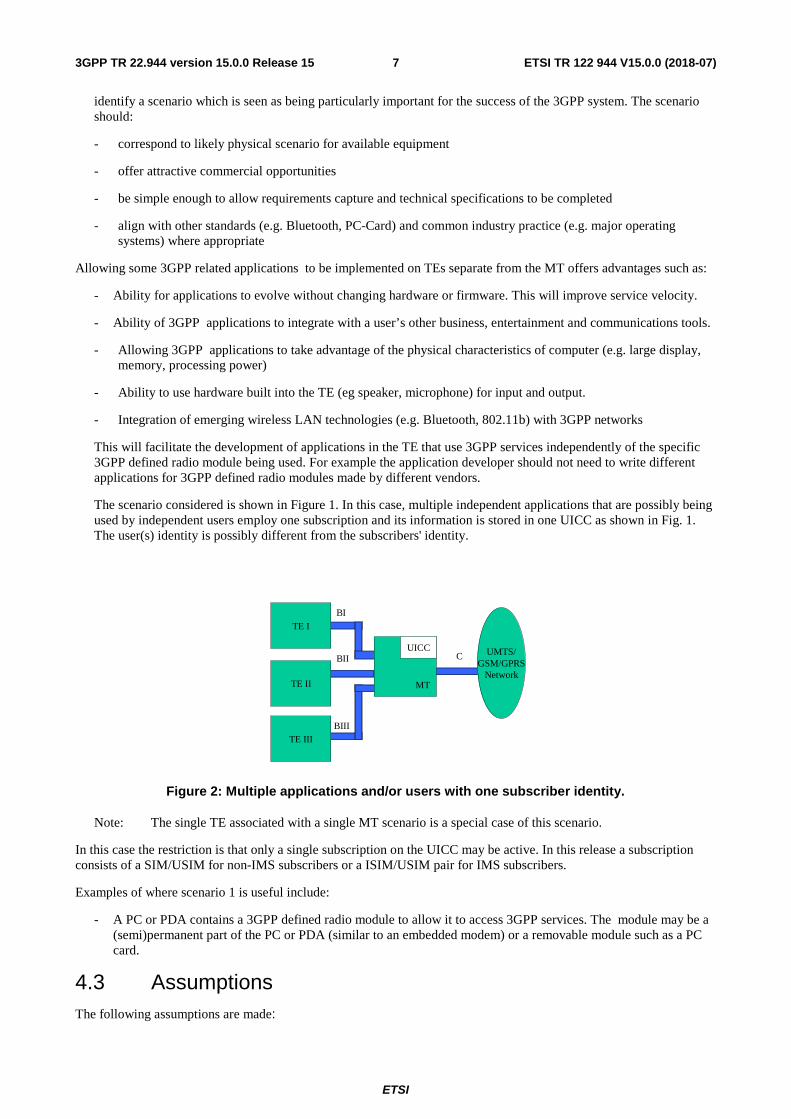
The scenario considered is shown in Figure 1. In this case, multiple independent applications that are possibly being used by independent users employ one subscription and its information is stored in one UICC as shown in Fig. 1. The user(s) identity is possibly different from the subscribers' identity.
TE I
UMTS/GSM/GPRS
Network
TE III
TE II MT
UICCC
BI
BII
BIII
Figure 2: Multiple applications and/or users with one subscriber identity.
Note: The single TE associated with a single MT scenario is a special case of this scenario.
In this case the restriction is that only a single subscription on the UICC may be active. In this release a subscription consists of a SIM/USIM for non-IMS subscribers or a ISIM/USIM pair for IMS subscribers.
Examples of where scenario 1 is useful include:
- A PC or PDA contains a 3GPP defined radio module to allow it to access 3GPP services. The module may be a (semi)permanent part of the PC or PDA (similar to an embedded modem) or a removable module such as a PC card.
4.3 Assumptions The following assumptions are made:

ETSI
ETSI TR 122 944 V15.0.0 (2018-07)83GPP TR 22.944 version 15.0.0 Release 15
a The transport link between the TE and MT functions of the UE is not necessarily secure.
b A SIM/USIM application resident on a UICC is required to access the 3GPP system . Only a single USIM on a UICC can be active at any time (multiple USIMs can be located on a UICC).
c Charging is linked to one particular USIM.
d The secret key and the authentication algorithm cannot be transferred out from the USIM.
e The UICC must be present during the entire duration of the call. Periodic UICC presence detection is mandatory during a call.
f Requirements identified in [3] regarding the ISIM must be fulfilled.
Note: In particular the following requirement from [3] is relevant: “For this release of UE-split the USIM and the ISIM shall reside on the same UICC (i.e., the ISIM application shall require the presence of a USIM application on the same UICC). This shall not preclude the possibility in later releases of having an ISIM in a UICC that does not contain a USIM.”
Note: The following maybe later moved into an appropriate stage 2 document if considered necessary. The functionality split required in this case corresponds to generic way computers treat other types of network interface cards. In this configuration the basic 3GPP protocols are implemented in the 3GPP defined radio module (see figure below). The computer contains the following elements:
- driver software to control the 3GPP radio module and interface it to the computer operating system
- software applications using network protocols (such as IP) which are routed to other computers via the card.
MT (UMTS Module eg a PC Card)
TE (Computer eg a PC)
UICC
Basic UMTS Protocols?
UMTS Driver Software?
Operating System
Application API
Software elements
Key
Figure 3: Assumed Topology
5 Requirements Requirements are identified for only the single active subscription for each TE-MT combination case. Requirements for the other more general cases may be added in later releases.
5.1 General 1 The functionality split proposed applies to Circuit Switched (CS) domain.
2 The functionality split proposed applies to the Packet Switched (PS) domain.
3 The user should be able to control which MTs and TEs are part of their user equipment combination.
ETSI
ETSI TR 122 944 V15.0.0 (2018-07)93GPP TR 22.944 version 15.0.0 Release 15
4 A standardized API for access to capabilities provided by an MT (TE) towards a TE (MT) across Operating Systems must be provided.
5 It must be possible to develop applications in the TE that use 3GPP services independently of the specific 3GPP defined radio module being used. For example the application developer should not need to write different applications for 3GPP defined radio modules made by different companies.
6 Control over those radio aspects as currently available with AT commands should be provided to the TE by the MT. Access to additional functions is not required.
7. Call control signalling (e.g. IMS SIP signalling) must not be run transparently through the MT by the TE in this Release. [Note: This requirement is FFS currently under review.].
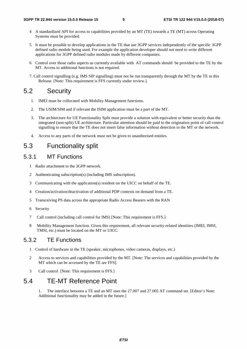
5.2 Security 1. IMEI must be collocated with Mobility Management functions.
2. The USIM/SIM and if relevant the ISIM application must be a part of the MT.
3. The architecture for UE Functionality Split must provide a solution with equivalent or better security than the integrated (non-split) UE architecture. Particular attention should be paid to the origination point of call control signalling to ensure that the TE does not insert false information without detection in the MT or the network.
4. Access to any parts of the network must not be given to unauthorised entities.
5.3 Functionality split
5.3.1 MT Functions
1 Radio attachment to the 3GPP network.
2 Authenticating subscription(s) (including IMS subscription).
3 Communicating with the application(s) resident on the UICC on behalf of the TE.
4 Creation/activation/deactivation of additional PDP contexts on demand from a TE.
5 Transceiving PS data across the appropriate Radio Access Bearers with the RAN
6 Security
7 Call control (including call control for IMS) [Note: This requirement is FFS.]
8 Mobility Management function. Given this requirement, all relevant security-related identities (IMEI, IMSI, TMSI, etc.) must be located on the MT or UICC.
5.3.2 TE Functions
1 Control of hardware in the TE (speaker, microphones, video cameras, displays, etc.)
2 Access to services and capabilities provided by the MT. [Note: The services and capabilities provided by the MT which can be accessed by the TE are FFS].
3 Call control [Note: This requirement is FFS.]
5.4 TE-MT Reference Point 1. The interface between a TE and an MT uses the 27.007 and 27.005 AT command set. [Editor’s Note: Additional functionality may be added in the future.]

ETSI
ETSI TR 122 944 V15.0.0 (2018-07)103GPP TR 22.944 version 15.0.0 Release 15
Annex A: Example Scenarios These scenarios were studied and deferred to a later release. They are not enabled by the requirements outlined in this TR.
Scenario 2
In this case, multiple SIM/USIM applications are stored on the MT on a single UICC. Each application (that may be associated with its own unique user) has its own unique SIM/USIM associated with it. The billing is associated with the subscriber's identity stored in the SIM/USIM.
TE I
UMTSGSM/GPRS
Network
TE III
TE II
MT
C
BI
BII
BIII
USIM1
USIM2
USIM3
UICC
Figure 1 - Multiple users, multiple “borrowed” subscriber identities.
Editors Note: Release 99 allows multiple USIMs stored to be stored on a UICC but they cannot be all active at the same time. In Release 4, the support of logical channels on the UICC enables multiple USIM activation. However, for any registered UICC it is assumed that only one SIM/USIM can be active at any given time.
The scenarios discussed above can be divided into two categories based on the number of simultaneously active subscriptions per user equipment configuration. Scenario 1 and Scenario 2 are examples of cases where there is a single active subscription per UE. This implies that for these scenarios:
1) The user equipment combination shall contain only one active SIM/USIM.
2) The user equipment combination shall contain only one active MT.
3) All MTs and TEs in a particular user equipment combination shall be treated by the 3GPP system as being under the responsibility of the subscription identified by the active SIM/USIM. All charges made by 3GPP shall be directed to the subscriber identified by the SIM/USIM.
Note: It is possible that charges that are not related to the 3GPP subscription may be treated differently for different TEs in the same user equipment combination. For example a user on a TE may access an Internet service which charges them based on a credit-card or a subscription that is not associated with 3GPP.
Note: If a 3GPP subscriber permits a TE to be connected to their user equipment combination they shall be willing to accept any charges as a result of this. This is similar to the situation where you lend your phone to another person to allow them to make a call.
Scenario 3

ETSI
ETSI TR 122 944 V15.0.0 (2018-07)113GPP TR 22.944 version 15.0.0 Release 15
In this case, every user uses subscription per device and each device (e.g. PC, PDA) have a UICC. The MT does not use an UICC, even if an UICC is physically present. In this case, each TE is independent and billed for separately. The MT in this case is used as transmitter with multiplexing capabilities and the CK and the IK are handled by the TEs
TE I
UMTSGSM/GPRS
Network
TE III
TE II
UICC
MT
BI
BII
BIII
UICC
UICC
C
Figure 3 - Multiple users, multiple “owned” subscriber identities.
Due to security concerns this case is not possible, since USIM/SIM applications must be collocated with the Mobility Management on the MT. (It is assumed that the Mobility Management functions are located on the MT).
Scenario 4
In this scenario, every user has a subscription i.e. each user has one UICC that resides in a device (TE + MT) such as the mobile phone (like in case 3). However, the user may be able to transition (henceforth, handoff) into using a different MT (which has a UICC with a SIM/USIM application resident) as shown in the figure below.
RadioNetwork
UICCTERadio
Network
Before Hand-off
TE UICC
UICC
Car ModuleAfter Hand-off
C
CB
Figure 2: Hand-off to a “borrowed” subscriber identity.
Comments: Hand-off during ”IDLE” state may be possible for CS/PS domains using existing services offered by each domain. Significant issues arise if this must be accomplished during ”active” state. The assumption is that the handoff is accomplished using existing supplementary services (call forwarding, explicit call transfer etc). This is under the assumption that after the handoff the functional split will be the same as the TE and MT split case discussed earlier.

ETSI
ETSI TR 122 944 V15.0.0 (2018-07)123GPP TR 22.944 version 15.0.0 Release 15
TE II
UMTSGSM/GPRS
NetworkCar
Module
TE I
UICCUICCB C
Figure 3: Hand-off, but retain and lend “own” subscriber identity.
In a variation of the scenario under consideration, it may conceivably be possible to use the UICC on the TE while using a borrowed MT. However, this is not possible since the USIM/SIM application and the MM funtion should be collocated and on the MT.
ETSI
ETSI TR 122 944 V15.0.0 (2018-07)133GPP TR 22.944 version 15.0.0 Release 15
Annex B: Scenarios for possible functionality split for the Circuit domain This annex identifies scenarios for possible functionality split for the Circuit domain. It is expected that these scenarios will aid in deciding the functionality splits to be supported. Note that the scenarios enumerated here may not be exhaustive yet and others may be added.
B.1 Telephony
This section deals with circuit-switched voice Telephony.
B.1.1 Functional Elements
The following functional elements are identified as being applicable to the Telephony service:
B.1.1.1 Call Control and Mobility Management (CC&MM)
The Call Control and Mobility Management entity is a C-plane function which supports the signalling for call control and mobility management. The actions of the CC&MM may be initiated directly by the user using a local HMI, or by a Call Control Client on a remote device.
B.1.1.2 Call Control Client (CCC)
The Call Control Client is a client that interfaces to the CC&MM to provide service. The protocol between the CCC and the CC&MM is an intermediate protocol that allows the CCC to signal its call setup and release requirements.
B.1.1.3 Codec
The codec is a U-plane entity responsible for applying the radio-interface voice coding to a PCM or analogue signal.
B.1.1.4 Transducer
The transducer a U-plane entity responsible for converting between physical sound waves and electrical signals.
B.1.1.5 Radio Resource Layers (RR)
The Radio Resource Layers cover the C-plane and the U-plane. They are responsible for all low-level protocols on the radio interface – including the MAC and physical layers.

ETSI
ETSI TR 122 944 V15.0.0 (2018-07)143GPP TR 22.944 version 15.0.0 Release 15
B.1.2 Telephony Scenarios
B.1.2.1 Telephony Scenario 1 - Headsets
Telephony scenario 1 corresponds to the use of a headset to access the telephony service. Though a headset is not normally considered to be a TE, from a formal point of view it is an external device connected to the MT and therefore should strictly be included in the discussion. As the question of support for wireless headsets has frequently been mentioned in conjunction with UE-split it is felt necessary to include this scenario for completeness. The model presented is applicable to both wired and wireless headsets.
In Telephony Scenario 1 the TE only contains the transducer. All other functions are included in the MT.
Telephony Scenario 1
B.1.2.2 Telephony Scenario 2 – Telephony Control Application in TE
This scenario corresponds to the use of a TE (a PC or a PDA) which contains a function to control telephony calls on behalf of the user. This might be a telephone dialler application linked to a contacts database. APIs like “TAPI” are typically used to provide this interface to applications. On the R-interface the AT-command set provides some of the required functionality. In this scenario the user’s voice is still handled only in the MT.
Telephony Scenario 2
B.1.2.3 Telephony Scenario 3 – Telephony Supported in TE
In this scenario the HMI for the Telephony teleservice is supported in the TE. This may correspond to a user who uses their PC or PDA to initiate calls (the above scenario), but also wants to multiplex the audio component of their calls on to their PCs sound-channel so they can also use the PC’s MP3 or CD player via the same transducer.
The U-plane interface between the TE and the MT is assumed to be PCM or a similar light-weight encoding.
NOTE: This scenario raises the interesting question of TE-split! In this case it is likely the transducer is not physically integrated with the TE, but is in fact a headset connected to the TE. At this level of modelling it is assumed that the internal structure of the TE (even if it is itself made up of several components) is not important provided this doesn’t change the TE-MT interface.
TransducerRR
Codec CC&MM
TE MT
Transducer
RR
CC&MM Codec
TE MT
CCC

ETSI
ETSI TR 122 944 V15.0.0 (2018-07)153GPP TR 22.944 version 15.0.0 Release 15
Telephony Scenario 3
TransducerRR
CC&MM
Codec
TE MT
CCC

ETSI
ETSI TR 122 944 V15.0.0 (2018-07)163GPP TR 22.944 version 15.0.0 Release 15
B.2 Circuit Bearer Services
This section deals with the circuit-mode data bearer services
B.2.1 Functional Elements
The following functional elements are identified as being applicable to the Circuit Bearer Services:
B.2.1.1 Call Control and Mobility Management (CC&MM)
As for telephony.
B.2.1.2 Call Control Client (CCC)
As for Telephony
B.2.1.3 Terminal Adaptation Function (TAF)
The TAF maps the data format on the R-interface in to the format needed for the bearer.
B.2.1.4 Data Termination (DT)
The data termination is the end-point in the user-equipment for the bearer service. The DT is outside the scope of the 3GPP standard.
B.2.1.5 Radio Resource Layers (RR)
As for Telephony
B.2.2 Circuit Bearer Scenarios
B.2.2.1 Circuit Bearer Scenario 1 – PC or PDA Access
This scenario corresponds to a PC or PDA that uses the circuit bearer service. This scenario is supported by the existing R-interface standards.
Circuit Bearer Scenario 1
RR
CC&MM
TAF
TE MT
CCC
DT

ETSI
ETSI TR 122 944 V15.0.0 (2018-07)173GPP TR 22.944 version 15.0.0 Release 15
B.4. Packet-Based Data Scenarios
B.4.1. Functional Elements
B.4.1.1 Session Management and Mobility Management (SM &MM)
The Session Management and Mobility Management entity is a C-plane function which supports the signalling for session management and mobility management. Session management includes the establishment, management and release of PDP contexts. The actions of the SM&MM may be initiated directly by the user using a local HMI, or by a Session Management Client on a remote device. This function does not include the SIP client.
B.4.1.2 Session Management Client (SMC)
The Session Management Client is a client that interfaces to the SM&MM to provide service. The protocol between the SMC and the SM&MM is an intermediate protocol that allows the SMC to signal its session setup and release requirements. This is a peer to the SM&MM and does not include SIP
B.4.1.3 SIP Client (SC)
The SIP-client terminates IMS signalling in the user equipment. It is responsible for all the control signalling between the user equipment and the elements of the IMS domain in the network.
B.4.1.4 IP Adaptation Function (IPAF)
The IPAF is a U-plane function that does the high-level mapping of IP data in to the UMTS bearer.
B.4.1.5 IP Data Termination (IPDT)
The IP Data Termination is the end-point in the user-equipment for the IP bearer service provided by the PS-domain. Note that the IPDT is not intended to be part of the IMS. Rather it represents other IP applications that may exist.
B.4.1.6 IMS Media Coding (IMC)
The IMS media coding is similar to the codec in the Telephony service. It converts media formats to those used for IMS. The IMC may support many types of media including speech and video.
B.4.1.7 Multimedia Transducers
The multimedia transducers convert between the physical works and electronic representation of multimedia content. They include microphones, speakers, displays etc.
B.4.1.8 Radio Resource Layers (RR)
As for telephony.
B.4.2 Packet-Based Data Scenarios
B.4.2.1 Packed-Based Data Scenario 1 – PC or PDA Access
This scenario corresponds to a PC or PDA that uses the packet bearer service. This scenario is partially supported by the existing R-interface standards.
Packet Based Data Scenario
RR
SM&MM
IPAF
TE MT
SMC
IPDT
ETSI
ETSI TR 122 944 V15.0.0 (2018-07)183GPP TR 22.944 version 15.0.0 Release 15
B.4.3 IMS Scenarios
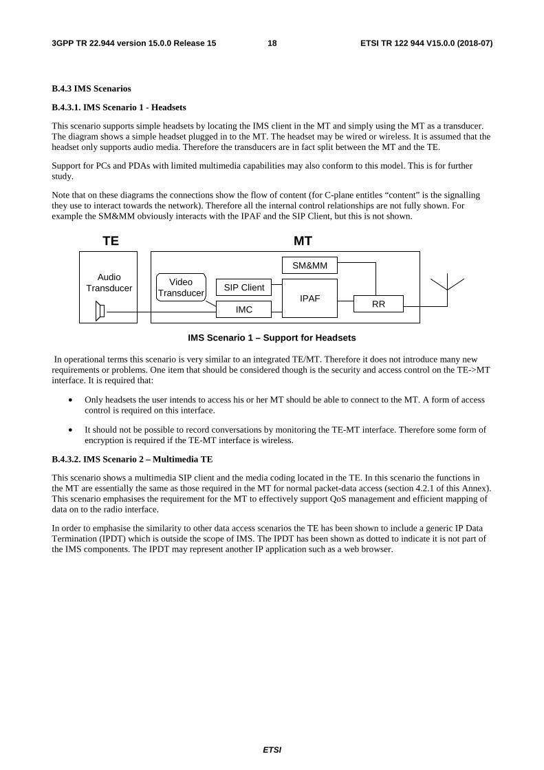
B.4.3.1. IMS Scenario 1 - Headsets
This scenario supports simple headsets by locating the IMS client in the MT and simply using the MT as a transducer. The diagram shows a simple headset plugged in to the MT. The headset may be wired or wireless. It is assumed that the headset only supports audio media. Therefore the transducers are in fact split between the MT and the TE.
Support for PCs and PDAs with limited multimedia capabilities may also conform to this model. This is for further study.
Note that on these diagrams the connections show the flow of content (for C-plane entitles “content” is the signalling they use to interact towards the network). Therefore all the internal control relationships are not fully shown. For example the SM&MM obviously interacts with the IPAF and the SIP Client, but this is not shown.
IMS Scenario 1 – Support for Headsets
In operational terms this scenario is very similar to an integrated TE/MT. Therefore it does not introduce many new requirements or problems. One item that should be considered though is the security and access control on the TE->MT interface. It is required that:
• Only headsets the user intends to access his or her MT should be able to connect to the MT. A form of access control is required on this interface.
• It should not be possible to record conversations by monitoring the TE-MT interface. Therefore some form of encryption is required if the TE-MT interface is wireless.
B.4.3.2. IMS Scenario 2 – Multimedia TE
This scenario shows a multimedia SIP client and the media coding located in the TE. In this scenario the functions in the MT are essentially the same as those required in the MT for normal packet-data access (section 4.2.1 of this Annex). This scenario emphasises the requirement for the MT to effectively support QoS management and efficient mapping of data on to the radio interface.
In order to emphasise the similarity to other data access scenarios the TE has been shown to include a generic IP Data Termination (IPDT) which is outside the scope of IMS. The IPDT has been shown as dotted to indicate it is not part of the IMS components. The IPDT may represent another IP application such as a web browser.
RR
SM&MM
IPAF
TE MT
IMC
SIP ClientAudio
TransducerVideo
Transducer

ETSI
ETSI TR 122 944 V15.0.0 (2018-07)193GPP TR 22.944 version 15.0.0 Release 15
IMS Scenario 2 – Support for Multimedia TEs
In this scenario important UMTS functions are located outside the MT. This means that the system aspects need to be understood. The most important of these are discussed in the following sections.
B.4.3.3. IMS Scenario 3 – Multimedia TE without Codecs
This scenario is intermediate between the other two. It recognises the fact that in the short-term the implementation of media codecs presents special problems for TE hardware. Also the location of codecs outside the MT may complicate the efficient management of the radio interface. Therefore in this model the codecs are located in the MT while the SIP client is contained in the TE.
In this model the requirements and issues are similar to the case above. However some of the complexity in the areas of delay and radio efficiency are avoided. The cost of this simplification is less flexibility in terms of support of new media formats and a system design which is less compatible with other access types.
IMS Scenario 3 – Support for Multimedia TEs without codecs
B.4.4. IMS Security and system integrity
The TE – MT link needs to include both confidentiality and access control. These security requirements are similar in any UE-split scenario including the IMS-headset scenario described above.
Locating UMTS functions such as the SIP client outside the MT may be seen as introducing other security risks that arise because of malicious or poorly implemented SIP clients, however these security risks exist for non-split UEs as well. The network must therefore be secure against attacks which may result from maliciously modified SIP clients.
It is possible that the client may attempt to attack nodes in the IMS directly. In order to control this the IMS must include adequate firewalling and IP-based security procedures. These functions should be placed in the network rather than the user equipment so that they cannot be tampered with, and so they can be adapted to meet new threats. Because of the IP-based nature of IMS the security of this network from IP-based attacks needs to be considered whether or not IMS clients are implemented in the TE according to the standard.
RR
SM&MM
IPAF
TE
MT
IMC
SIP ClientAudioTransducer
VideoTransducer
SMC
IP DT
RR
SM&MM
IPAF
TE
MT
IMC
SIP Client
AudioTransducer
VideoTransducer
SMC
IP DT

ETSI
ETSI TR 122 944 V15.0.0 (2018-07)203GPP TR 22.944 version 15.0.0 Release 15
B.4.5 End to end delay
End to end delay in IMS scenario 2 is a function of many factors. These includes the hardware on the TE, the codecs in the TE, the mapping of data over the TE-MT interface and the UMTS radio interface. In order to ensure that system-wide delay is managed it is important that:
• The total maximum end-to-end delay limits are defined in 3GPP
• A delay budget is created showing the maximum contribution to the delay at each point in the network
• The technical design of the standard takes in to account delay aspects, and that the interfaces are created in a way where both the theoretical and practical delay consequences are compatible with the delay budget.
• Approved implementations are tested to ensure they meet delay requirements.
5.3 Radio Efficiency
This scenario is not necessarily less radio efficient than other IMS scenarios provided that:
• The MT has sufficient information about the different IP streams it is transporting to map then on to the correct radio access bearer, and
• The IP header compression mechanism on the radio interface supports header stripping and reassembly to support the transparency of the service.
The first point requires developments in the TE’s operating system and also on the TE-MT interface.

ETSI
ETSI TR 122 944 V15.0.0 (2018-07)213GPP TR 22.944 version 15.0.0 Release 15
Annex C: Change history
Change history
TSG SA# SA Doc. SA1 Doc Spec CR Rev Rel Cat Subject/Comment Old New Work Item
SP-020064 S1-020664 22.944 Approved at SP-15 2.0.0 5.0.0
SP-16 SP-020253 S1-021134 22.944 001 Rel-5 F Editorial Corrections to TR 22.944
5.0.0 5.1.0 UESPLIT-TR
SP-16 SP-020253 S1-021132 22.944 002 Rel-5 F UICC in UE-split 5.0.0 5.1.0 UESPLIT-TR
SP-26 SP-040744 S1-040997 22.944 Rel-6 Updated from Rel-5 to Rel-6 5.1.0 6.0.0
SP-36 22.944 Rel-7 Updated from Rel-6 to Rel-7 6.0.0 7.0.0
SP-42 - - Rel-8 Updated from Rel-7 to Rel-8 7.0.0 8.0.0
SP-42 - - Rel-8 Updated from Rel-7 to Rel-8 7.0.0 8.0.0
SP-46 - - - - - - - Updated to Rel-9 by MCC 8.0.0 9.0.0
2011-03 - - - - - - - Update to Rel-10 version (MCC) 9.0.0 10.0.0
2012-09 - - - - - - - Updated to Rel-11 by MCC 10.0.0 11.0.0
2014-10 Updated to Rel-12 by MCC 11.0.0 12.0.0
2015-12 - - - - - - - Updated to Rel-13 by MCC 12.0.0 13.0.0
2017-03 - - - - - - - Updated to Rel-14 by MCC 13.0.0 14.0.0
2018-06 - - - - - - - Updated to Rel-15 by MCC 14.0.0 15.0.0

ETSI
ETSI TR 122 944 V15.0.0 (2018-07)223GPP TR 22.944 version 15.0.0 Release 15
History
Document history
V15.0.0 July 2018 Publication