tr 101 578 - v1.3.1 - speech and multimedia transmission ... · 8 etsi tr 101 578 v1.3.1 (2018-10)...
TRANSCRIPT

ETSI TR 101 578 V1.3.1 (2018-10)
Speech and multimedia Transmission Quality (STQ); QoS aspects of TCP-based video services like YouTube™
TECHNICAL REPORT

ETSI
ETSI TR 101 578 V1.3.1 (2018-10) 2
Reference RTR/STQ-00220m
Keywords measurement, QoS, service, TCP-based video
services
ETSI
650 Route des Lucioles F-06921 Sophia Antipolis Cedex - FRANCE
Tel.: +33 4 92 94 42 00 Fax: +33 4 93 65 47 16
Siret N° 348 623 562 00017 - NAF 742 C
Association à but non lucratif enregistrée à la Sous-Préfecture de Grasse (06) N° 7803/88
Important notice
The present document can be downloaded from: http://www.etsi.org/standards-search
The present document may be made available in electronic versions and/or in print. The content of any electronic and/or print versions of the present document shall not be modified without the prior written authorization of ETSI. In case of any
existing or perceived difference in contents between such versions and/or in print, the only prevailing document is the print of the Portable Document Format (PDF) version kept on a specific network drive within ETSI Secretariat.
Users of the present document should be aware that the document may be subject to revision or change of status. Information on the current status of this and other ETSI documents is available at
https://portal.etsi.org/TB/ETSIDeliverableStatus.aspx
If you find errors in the present document, please send your comment to one of the following services: https://portal.etsi.org/People/CommiteeSupportStaff.aspx
Copyright Notification
No part may be reproduced or utilized in any form or by any means, electronic or mechanical, including photocopying and microfilm except as authorized by written permission of ETSI.
The content of the PDF version shall not be modified without the written authorization of ETSI. The copyright and the foregoing restriction extend to reproduction in all media.
© ETSI 2018.
All rights reserved.
DECTTM, PLUGTESTSTM, UMTSTM and the ETSI logo are trademarks of ETSI registered for the benefit of its Members. 3GPPTM and LTETM are trademarks of ETSI registered for the benefit of its Members and
of the 3GPP Organizational Partners. oneM2M logo is protected for the benefit of its Members.
GSM® and the GSM logo are trademarks registered and owned by the GSM Association.
ETSI
ETSI TR 101 578 V1.3.1 (2018-10) 3
Contents
Intellectual Property Rights ................................................................................................................................ 7
Foreword ............................................................................................................................................................. 7
Modal verbs terminology .................................................................................................................................... 7
Introduction ........................................................................................................................................................ 7
1 Scope ........................................................................................................................................................ 9
2 References ................................................................................................................................................ 9
2.1 Normative references ......................................................................................................................................... 9
2.2 Informative references ........................................................................................................................................ 9
3 Abbreviations ........................................................................................................................................... 9
4 Quality of Service measurements for IP-based video services like YouTube™ .................................... 10
4.0 General ............................................................................................................................................................. 10
4.1 Phases of IP-based video services .................................................................................................................... 10
4.2 QoS aspects of IP-based video services ........................................................................................................... 12
4.2.0 Scope of aspects .......................................................................................................................................... 12
4.2.1 Video start and time to first picture ............................................................................................................ 12
4.2.2 Video freezes .............................................................................................................................................. 12
4.2.3 Adaptive videostreaming ............................................................................................................................ 12
4.2.4 Perceived video quality ............................................................................................................................... 13
4.3 QoS parameters for IP-based video services .................................................................................................... 13
4.3.0 Parameter and trigger points ....................................................................................................................... 13
4.3.1 Video Access Failure Ratio [%] ................................................................................................................. 14
4.3.2 Video Access Time [s] ................................................................................................................................ 15
4.3.3 Void ............................................................................................................................................................ 15
4.3.4 Void ............................................................................................................................................................ 15
4.3.5 Void ............................................................................................................................................................ 15
4.3.6 Void ............................................................................................................................................................ 15
4.3.7 Void ............................................................................................................................................................ 15
4.3.8 Void ............................................................................................................................................................ 15
4.3.9 Void ............................................................................................................................................................ 15
4.3.10 Void ............................................................................................................................................................ 15
4.3.11 Void ............................................................................................................................................................ 15
4.3.12 Void ............................................................................................................................................................ 15
4.3.13 Void ............................................................................................................................................................ 15
4.3.14 Void ............................................................................................................................................................ 15
4.3.15 Void ............................................................................................................................................................ 15
4.3.16 Void ............................................................................................................................................................ 15
4.3.17 Impairment Free Video Session Ratio [%] ................................................................................................. 15
4.3.18 Void ............................................................................................................................................................ 16
4.3.19 Void ............................................................................................................................................................ 16
4.3.20 Void ............................................................................................................................................................ 16
4.3.21 Void ............................................................................................................................................................ 16
4.3.22 Void ............................................................................................................................................................ 16
4.3.23 Impairment Free Video Session Ratio [%] ................................................................................................. 16
4.3.24 Video Playout Cut-off Ratio [%] ................................................................................................................ 16
4.3.25 Void ............................................................................................................................................................ 16
4.3.26 Void ............................................................................................................................................................ 16
4.3.27 Video Playout Duration [s] ......................................................................................................................... 16
4.3.28 Void ............................................................................................................................................................ 16
4.3.29 Accumulated Video Freezing Duration [s] ................................................................................................. 16
4.3.30 Void ............................................................................................................................................................ 17
4.3.31 Void ............................................................................................................................................................ 17
4.3.32 Void ............................................................................................................................................................ 17
4.3.33 Void ............................................................................................................................................................ 17
4.3.34 Video Freezing Time Proportion ................................................................................................................ 17

ETSI
ETSI TR 101 578 V1.3.1 (2018-10) 4
4.3.35 Video Quality .............................................................................................................................................. 17
4.4 Recommended supplementary information for IP-based video service measurements .................................... 17
4.4.0 Introduction................................................................................................................................................. 17
4.4.1 Video Preparation Failure Ratio [%] .......................................................................................................... 18
4.4.2 Video Preparation Time [s] ......................................................................................................................... 18
4.4.3 Pre-Playout Buffering Failure Ratio [%] .................................................................................................... 18
4.4.4 Pre-Playout Buffering Time [s] .................................................................................................................. 18
4.5 Configuration aspects including timeout recommendations for IP-based video service measurements .......... 19
4.5.0 Purpose ....................................................................................................................................................... 19
4.5.1 URL ............................................................................................................................................................ 19
4.5.2 Timeouts ..................................................................................................................................................... 19
4.5.2.0 Application of timeouts ......................................................................................................................... 19
4.5.2.1 Video Access timeout ........................................................................................................................... 19
4.5.3 Video Playout Duration .............................................................................................................................. 19
4.5.4 Handling of video freezes ........................................................................................................................... 20
4.5.4.0 Use of freezes ........................................................................................................................................ 20
4.5.4.1 Minimum freeze duration ...................................................................................................................... 20
4.5.4.2 Maximum duration of single freeze ...................................................................................................... 20
4.5.4.3 Maximum duration of all freezes .......................................................................................................... 20
4.5.4.4 Maximum number of freezes ................................................................................................................ 20
4.5.5 Timeout and Threshold Frameworks .......................................................................................................... 20
4.5.6 Hide video during playout .......................................................................................................................... 21
4.5.7 Play until the end ........................................................................................................................................ 21
4.5.8 Cache and cookies ...................................................................................................................................... 21
4.5.9 Video Resolution characteristics of the clip test ......................................................................................... 21
4.6 Impacts of measurement hardware for IP-based video service measurements ................................................. 21
Annex A: Void ........................................................................................................................................ 23
History .............................................................................................................................................................. 24

ETSI
ETSI TR 101 578 V1.3.1 (2018-10) 5
List of figures Figure 1: Typical phases of IP-based video services .........................................................................................................11

ETSI
ETSI TR 101 578 V1.3.1 (2018-10) 6
List of tables Table 1: Overview of QoS parameters and mapping to typical phases of the video services as experienced by the user.13
Table 2: Overview of the trigger points used for the QoS parameter definition ...............................................................14
Table 3: Example settings that do model a standard user ..................................................................................................21
ETSI
ETSI TR 101 578 V1.3.1 (2018-10) 7
Intellectual Property Rights
Essential patents
IPRs essential or potentially essential to normative deliverables may have been declared to ETSI. The information pertaining to these essential IPRs, if any, is publicly available for ETSI members and non-members, and can be found in ETSI SR 000 314: "Intellectual Property Rights (IPRs); Essential, or potentially Essential, IPRs notified to ETSI in respect of ETSI standards", which is available from the ETSI Secretariat. Latest updates are available on the ETSI Web server (https://ipr.etsi.org/).
Pursuant to the ETSI IPR Policy, no investigation, including IPR searches, has been carried out by ETSI. No guarantee can be given as to the existence of other IPRs not referenced in ETSI SR 000 314 (or the updates on the ETSI Web server) which are, or may be, or may become, essential to the present document.
Trademarks
The present document may include trademarks and/or tradenames which are asserted and/or registered by their owners. ETSI claims no ownership of these except for any which are indicated as being the property of ETSI, and conveys no right to use or reproduce any trademark and/or tradename. Mention of those trademarks in the present document does not constitute an endorsement by ETSI of products, services or organizations associated with those trademarks.
Foreword This Technical Report (TR) has been produced by ETSI Technical Committee Speech and multimedia Transmission Quality (STQ).
Modal verbs terminology In the present document "should", "should not", "may", "need not", "will", "will not", "can" and "cannot" are to be interpreted as described in clause 3.2 of the ETSI Drafting Rules (Verbal forms for the expression of provisions).
"must" and "must not" are NOT allowed in ETSI deliverables except when used in direct citation.
Introduction There are a variety of popular IP-based video services available on the internet, on which users can view, upload and share videos. These services have become very popular and have a major share of the internet traffic worldwide. Due to their high popularity in general and use over mobile internet their availability and quality is of key interest for the provider of mobile internet access, which makes the services a matter for benchmarking. The down-stream scenario, the probability to access and see a desired video and the quality of the video is the subject of measurement method laid out in the present document.
Any video content is accessed via a link that is provided by the service on request. This request can be triggered by selecting a video on a web-page, by selecting a video in a smartphone application or – if the URL is known – by direct access of a video player with streaming capabilities. A popular example for a video streaming service is YouTube™.
NOTE: YouTube™ is the trade name of a product supplied by Google. This information is given for the convenience of users of the present document and does not constitute an endorsement by ETSI of the product named. Equivalent products may be used if they can be shown to lead to the same results.
Today's video streaming services are mainly based on reliable transmission. It is often TCP, but e.g. YouTube™ applies a proprietary protocol named QUIC. This protocol is based on UDP but secures transmission at a higher layer.

ETSI
ETSI TR 101 578 V1.3.1 (2018-10) 8
The source video, either uploaded by a user or provided e.g. by a broadcasting station or live stream is usually in high quality in high resolution. Typically, the receiving video server re-processes the video, add streaming information and is usually transcoding it to meet its coding schemes and data rate classes. In practice these videos are transcoded in different resolutions and stored for down-streaming by the video server.
State of the art video streaming services do not downstream the entire video in one pre-defined resolution (or bitrate), they adjust the amount of data to transport at the available channel capacity or restrictions given by the operators (called: adaptive bitrate). To adjust the amount of data the most efficient strategy is to change the image resolution. Other strategies are decreasing encoding depth or reducing the picture rate (frame-rate) of the video. It is obvious that the applied compression affects the perceived video quality, the degree of degradation is depending on compression and the strategy of compression.
Typically, the resolution is not changed continuously. It is usually switching between fixed resolutions as e.g. 240, 360, 480, 720 and 1 080 lines. The most common schemes for adaptive bitrate are DASH and HLS, where the video is requested in sub-sequent portions of a few seconds in a defined resolution.
On the other hand the clips not need to come physically from the same server since mobile operators employ proxies in order to move the content closer to their subscriber and the downlink bandwidth could be controlled by both the mobile operator network and the video service. Therefore the clips need to be streamed from the actual live network and may not be streamed from a dedicated server.
It should be considered that the rendering of the video and finally the quality of its reproduction depends on the buffering and decoding strategy of the player, as well as on the operating system and available system resources.
ETSI
ETSI TR 101 578 V1.3.1 (2018-10) 9
1 Scope The present document focuses on Quality of Service (QoS) measurements for IP-based video services with reliable transport where downloading and viewing takes place in parallel. In principle the presented measurement approach can be used for all video services, where the video is embedded in a HTML context as of video on demand services like e.g. YouTube™. Similar applications are also available on social networks.
In the following, QoS parameters to be used for such video service measurements are presented. The underlying procedure consists of two phases: first requesting a control script containing among other information a link to the content, and second, requesting this content. In the present document, YouTube™ serves as the default example but the described QoS parameters can easily be applied to other IP-based video services based on reliable transport.
Furthermore, the present document also offers practical guidance for measurement execution and evaluation of HTTP/HTTPS streaming QoS measurement.
The present document covers the video request and playout of the video. Other services offered by content providers such as e.g. uploading video or managing the private account are not covered.
2 References
2.1 Normative references Normative references are not applicable in the present document.
2.2 Informative references References are either specific (identified by date of publication and/or edition number or version number) or non-specific. For specific references, only the cited version applies. For non-specific references, the latest version of the referenced document (including any amendments) applies.
NOTE: While any hyperlinks included in this clause were valid at the time of publication, ETSI cannot guarantee their long term validity.
The following referenced documents are not necessary for the application of the present document but they assist the user with regard to a particular subject area.
[i.1] ETSI TS 102 250-2: "Speech and multimedia Transmission Quality (STQ); QoS aspects for popular services in mobile networks; Part 2: Definition of Quality of Service parameters and their computation".
[i.2] ETSI TS 102 250-5: "Speech and multimedia Transmission Quality (STQ); QoS aspects for popular services in mobile networks; Part 5: Definition of typical measurement profiles".
3 Abbreviations For the purposes of the present document, the following abbreviations apply:
CPU Central Processing Unit DASH Dynamic Adaptive Streaming over HTTP DNS Domain Name System FLV Flash® Video FTP File Transfer Protocol GPU Graphics Processing Unit HDD Hard Disk Drive HLS HTTP Live Streaming HTML HyperText Markup Language HTTP HyperText Transfer Protocol

ETSI
ETSI TR 101 578 V1.3.1 (2018-10) 10
HTTPS HTTP Secure IP Internet Protocol LAN Local Area Network NDIS Network Driver Interface Specification OS Operating System PC Personal Computer PEC Performance Enhancement Client QoS Quality of Service QUIC Quick UDP Internet Connection RTP Real-time Transport Protocol RTSP Real Time Streaming Protocol SYN TCP synchronize flag TCP Transmission Control Protocol UDP User Datagram Protocol URL Uniform Resource Locator WLAN Wireless Local Area Network
4 Quality of Service measurements for IP-based video services like YouTube™
4.0 General Many video services offer the videos in several resolutions and allows the viewer to select the resolution quality manually. However, most services apply an adaptive mode (called 'automatic' for YouTube™), where based on the transport channel performances or other information the chosen resolution (bitrate) and the Pre-Playout buffering time is adjusted adaptively to an optimum regarding video quality, avoiding freezing and long waiting time before the video reproduction starts. The maximum available resolution is defined by the video provider and often by the display of the user device.
4.1 Phases of IP-based video services Most IP-based video services, like the YouTube™ video service, are comprised of several phases which are mainly the set-up of a HTML context including the request for the actual video server location and the download of the video itself. It has to be considered that there is no sub-sequent download of HTML content and video rather a parallel set-up of many connections.
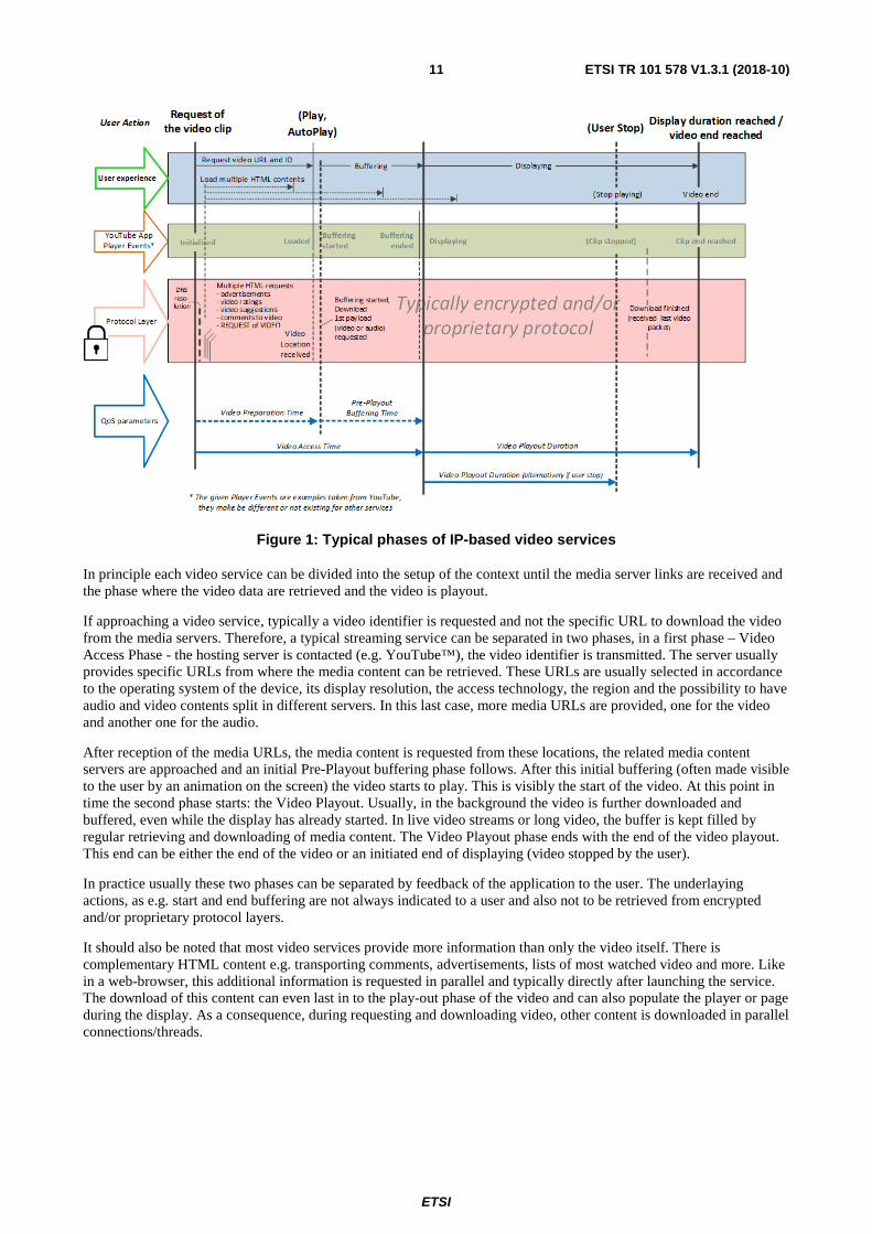
Figure 1 shows typical phases of IP-based video services, like YouTube™.
ETSI
ETSI TR 101 578 V1.3.1 (2018-10) 11
Figure 1: Typical phases of IP-based video services
In principle each video service can be divided into the setup of the context until the media server links are received and the phase where the video data are retrieved and the video is playout.
If approaching a video service, typically a video identifier is requested and not the specific URL to download the video from the media servers. Therefore, a typical streaming service can be separated in two phases, in a first phase – Video Access Phase - the hosting server is contacted (e.g. YouTube™), the video identifier is transmitted. The server usually provides specific URLs from where the media content can be retrieved. These URLs are usually selected in accordance to the operating system of the device, its display resolution, the access technology, the region and the possibility to have audio and video contents split in different servers. In this last case, more media URLs are provided, one for the video and another one for the audio.
After reception of the media URLs, the media content is requested from these locations, the related media content servers are approached and an initial Pre-Playout buffering phase follows. After this initial buffering (often made visible to the user by an animation on the screen) the video starts to play. This is visibly the start of the video. At this point in time the second phase starts: the Video Playout. Usually, in the background the video is further downloaded and buffered, even while the display has already started. In live video streams or long video, the buffer is kept filled by regular retrieving and downloading of media content. The Video Playout phase ends with the end of the video playout. This end can be either the end of the video or an initiated end of displaying (video stopped by the user).
In practice usually these two phases can be separated by feedback of the application to the user. The underlaying actions, as e.g. start and end buffering are not always indicated to a user and also not to be retrieved from encrypted and/or proprietary protocol layers.
It should also be noted that most video services provide more information than only the video itself. There is complementary HTML content e.g. transporting comments, advertisements, lists of most watched video and more. Like in a web-browser, this additional information is requested in parallel and typically directly after launching the service. The download of this content can even last in to the play-out phase of the video and can also populate the player or page during the display. As a consequence, during requesting and downloading video, other content is downloaded in parallel connections/threads.

ETSI
ETSI TR 101 578 V1.3.1 (2018-10) 12
4.2 QoS aspects of IP-based video services
4.2.0 Scope of aspects
When looking at impairments for a video streaming service, this clause focuses on objectively measurable impairments such as:
• failures to start
• video freezes
• low quality and resolution of the received video
NOTE: For test and measurement purposes, clips should be used that are available at least in high resolution as 1 080p and in good source quality. It is further recommended to avoid videos that have been stored on the video platform for several years already. They may show lower quality by previous, outdated encoding techniques in the source material.
4.2.1 Video start and time to first picture
After requesting a video by the user, the video URLs are requested and retrieved and a certain portion of the video is downloaded and buffered before the video starts to play. Usually, the video is considered as started if the first video frame is displayed. This waiting or access time is an important aspect of perceive QoE by the subscriber. In case the access time is too long, the user will stop waiting and close the video application.
4.2.2 Video freezes
Freezing events occur when the video playout stops (freezes) for a certain time, it is mainly caused by a buffer under-run but can also be caused by performance issues of the play-out devices. Usually, freezing events due to network issues and following buffer-underrun are > 1 or 2 s, while freezings due to performance issues on the playout device are usually < 500 ms.
Technically, freezing is an unusual long display time of a single picture or frame, regardless whether new frames received continuously but all carrying the same content, or there is no reception of new frames and the last received one is displayed until the video resumes. Today, there are multiple strategies how the video continues. Most often the video resumes at the same position (there is no video information lost). In live services it has to be considered that the lag to the real-time video signal increases. There are strategies, where after freezing a portion of the video is skipped to ensure a short delay to the source signal. There are also video services applying a fast-forward which means that after the freeze a certain portion of following video is played out faster to reduce the delay.
Despite the strategy applied, the main impact on perceived quality has the freezing event as such, meaning the frozen image. The impact depends on the motion of the content (freezings are considered as more annoying in case of high motion content) and the length of the freezing. The length dependency of the perceived impact is not linear but rather saturating for longer freezing times. The perceptual impact of freezing is considered in common methods to measure the video quality.
If a certain single freezing duration is exceeded, the video can be considered as dropped, because a human viewer would stop the service at this point. A good practice maximum waiting time for resuming the video is between 15 and 20 s.
4.2.3 Adaptive videostreaming
Adaptive bitrate video streaming techniques are able to adjust and change the video bitrate to the available transport channel capacity during the media download. Typical adaptive bitrate techniques are DASH and HLS. The purpose of those adaptive techniques is to avoid freezing caused by buffer-underrun during the reproduction of the video by adapting the video bitrate to the available transport channel bandwidth. The video bitrate itself is defined by the resolution, the used coding scheme and its coding depth.

ETSI
ETSI TR 101 578 V1.3.1 (2018-10) 13
To avoid a buffer under-run during the download the player requests the video portion-wise, where each portion is defined by a start and an end point in time and requested with a video bitrate according to the available transport channel bandwidth. Usually, the video server hosts all videos in different, dedicated quality classes (video bitrate levels) and the requested portion is than taken from the requested video bitrate level (often called 'quality class'). Therefore the employment of adaptive bitrate techniquescan lead to varying resolution and quality levels during the reproduction. It can also happen that the same content is downloaded in different quality levels in parallel or when increasing or decreasing the video bitrate.
4.2.4 Perceived video quality
There are multiple distortion types determining the perceived quality, as e.g. freezing, frame-rate resolution and compression depth and scheme by the codec. Each service, even each evolving version of a video application tries to optimize the perceived video quality by providing the least annoying amount of distortions; it is an optimized compromise between the player and production centre buffer depth (that increases waiting time or delay to real-time video), applied (lowered) resolution and compression strength. Target is always to avoid or at least to minimize freezing events during displaying. If DASH, HLS or another adaptive bitrate technique is used, the best compromise between the individual distortions can even be dynamically adjusted to the actual transport channel capacity.
To weigh and aggregate the individual distortion types and their occurrence during displaying according to their perceived quality, objective video quality measures are available and recommended. Measures especially applicable to mobile video applications are described in [i.1].
4.3 QoS parameters for IP-based video services
4.3.0 Parameter and trigger points
In this clause, a set of QoS parameters based on the streaming QoS parameters as defined in ETSI TS 102 250-2 [i.1] is proposed for measuring TCP-based video services.
Table 1 gives an overview of the proposed QoS parameters and provides a mapping of these parameters to the phases introduced in clause 4.1. Furthermore, a parameter type is assigned for each QoS parameter in order to determine the calculation method to be used for the respective parameter.
Table 1: Overview of QoS parameters and mapping to typical phases of the video services as experienced by the user
Related Phase(s) QoS parameter name QoS parameter type Video Access Video Access Failure Ratio Failure Ratio Video Access Video Access Time Duration Playout Video Playout Cut-off Ratio Cut-off Ratio Playout Video Playout Duration Duration Playout Impairment Free Video Session Ratio Calculation Playout Video Freezing Time Proportion Calculation Playout Video Quality Calculation
Within table 1, the following QoS parameter types are defined:
• Calculation;
• Count;
• Duration;
• Cut-off Ratio; and
• Failure Ratio.
The type "Calculation" is assigned to QoS parameters getting calculated based on other QoS parameters or other measurable qualities within the same single measurement, e.g. durations of single freezes.

ETSI
ETSI TR 101 578 V1.3.1 (2018-10) 14
The type "Count" is assigned to QoS parameters where the QoS parameter is calculated by counting occurrences of a certain event during a time period between a start trigger point and a stop trigger point, both observed during a single measurement. The following equations define the abstract equation to be used to calculate such a parameter:
=
triggerstop
gerstart trigi),( =Count eventtoccurence i
{ tat time occursevent if 1,else 0, =event)(t,occurrence
The type "Duration" is assigned to QoS parameters where the QoS parameter represents an expected or an actual time period between a start trigger point and a stop trigger point, both observed during a single measurement. The following equation defines the abstract equation to be used to calculate such a parameter:
( )[s] t- t=[s]Duration triggerstarttriggerstop
The type "{Failure | Cut-off} Ratio" is assigned to QoS parameters representing a failure or Cut-off ratio. The following equation defines the abstract equation to be used to calculate such a QoS parameter. Here, the term "unsuccessful attempt" should be understood in the way that, during a single measurement, the stop trigger point of the QoS parameter has not been observed within a given time after having observed the respective start trigger point.
100attempts all
attempts ulunsuccessf[%] Ratio off}-Cut | {Failure ×=
For the computation of the QoS parameter with type "Calculation", further information is given for each QoS parameter within the following clauses, if applicable.
Table 2 gives an overview of the trigger points used for the QoS parameter definition. For each trigger point, an ID is introduced. This ID will later be used as a reference within the QoS parameter definitions.
Table 2: Overview of the trigger points used for the QoS parameter definition
Trigger ID Abstract description Technical description
tr-1 Request of the clip The corresponding event in the APP or browser
tr-1a (see note 1)
Player start video download Start of Pre-Playout Buffering (see note 2)
tr-2 Start of video playout First frame displayed by the player tr-3 End of video playout reached Configured playout duration or clip end
reached NOTE 1: This trigger point is not available for all services. If available it can be used to calculated supplementary
QoS parameters as in clause 4.4. NOTE 2: Start of Pre-Playout Buffering event can be based alternatively on:
• The reception of the 1st payload video or audio packet request (if observable in the IP stream). • A status information by the App or player as e.g. 'start buffering'. • A visible graphical information on the screen as e.g. an animation indicating buffering.
From these observable events in connection with the observable phases the following QoS parameters can be identified.
4.3.1 Video Access Failure Ratio [%]
QoS parameter description Start
trigger ID
Stop trigger
ID The overall failure ratio for the video access. tr-1 tr-2

ETSI
ETSI TR 101 578 V1.3.1 (2018-10) 15
4.3.2 Video Access Time [s]
QoS parameter description Start
trigger ID
Stop trigger
ID The time it took for the video to start displaying. tr-1 tr-2
4.3.3 Void
4.3.4 Void
4.3.5 Void
4.3.6 Void
4.3.7 Void
4.3.8 Void
4.3.9 Void
4.3.10 Void
4.3.11 Void
4.3.12 Void
4.3.13 Void
4.3.14 Void
4.3.15 Void
4.3.16 Void
4.3.17 Impairment Free Video Session Ratio [%]
QoS parameter description Start
trigger ID
Stop trigger
ID The overall ratio of all videos that have been played without any impairment to the user in relation to the overall number of video playout attempts.
tr-2 tr-3
NOTE: Impairments in this context are (i) failures to start (ii) video freezes (iii failures to download completely. Please also refer to clause 4.2.

ETSI
ETSI TR 101 578 V1.3.1 (2018-10) 16
4.3.18 Void
4.3.19 Void
4.3.20 Void
4.3.21 Void
4.3.22 Void
4.3.23 Impairment Free Video Session Ratio [%]
The following equation defines the abstract equation to be used to calculate this parameter:
100attemptsplayout videoall ofnumber
simpairment w/oplayouts videoofnumber
[%] RatioSession Video Free Impairment
×
=
4.3.24 Video Playout Cut-off Ratio [%]
QoS parameter description Start
trigger ID
Stop trigger
ID The overall cut-off ratio for the video playout. tr-2 tr-3
4.3.25 Void
4.3.26 Void
4.3.27 Video Playout Duration [s]
QoS parameter description Start
trigger ID
Stop trigger
ID The time it took for the video to playout. tr-2 tr-3
4.3.28 Void
4.3.29 Accumulated Video Freezing Duration [s]
QoS parameter description Start
trigger ID
Stop trigger
ID The accumulated duration for all video freezes for successful playout starts.
tr-2 tr-3
NOTE: Freezes occur e.g. when video playout has started and needs to pause for re-buffering, but they can also occur in case of slow hardware, as the CPU and GPU load can be high during playout of highly compressed video.

ETSI
ETSI TR 101 578 V1.3.1 (2018-10) 17
The following equation defines the abstract equation to be used to calculate this parameter:
][)([s]Duration Freezing Video dAccumulate seVideofreezDuration
seOccuranceVideoFreezi
i=
=
4.3.30 Void
4.3.31 Void
4.3.32 Void
4.3.33 Void
4.3.34 Video Freezing Time Proportion
QoS parameter description Start
trigger ID
Stop trigger
ID The proportion of the accumulated video freezing duration in relation to the actual video playout duration (including freezings) for successful playout starts.
tr-2 tr-3
The following equation defines the abstract equation to be used to calculate this parameter:
4.3.35 Video Quality
QoS parameter description Start
trigger ID
Stop trigger
ID The average perceived video quality of the displayed video. tr-2 tr-3
4.4 Recommended supplementary information for IP-based video service measurements
4.4.0 Introduction
In particular with regards to trouble shooting purposes, certain supplementary observable quantities are recommended to include into the measurement results if made available from the service application, the bitstream analysis or the screen.
An important supplementary information is the start of downloading the video (start buffering). As indicators can be used alternatively:
• The reception of the 1st payload video or audio packet request (if observable in the IP stream)
• A status information by the App or player as e.g. 'start buffering'
Video Freezing Time Proportion [%] = Accumulated Video Freezing Duration [s]
Video Playout Duration [s] × 100
ETSI
ETSI TR 101 578 V1.3.1 (2018-10) 18
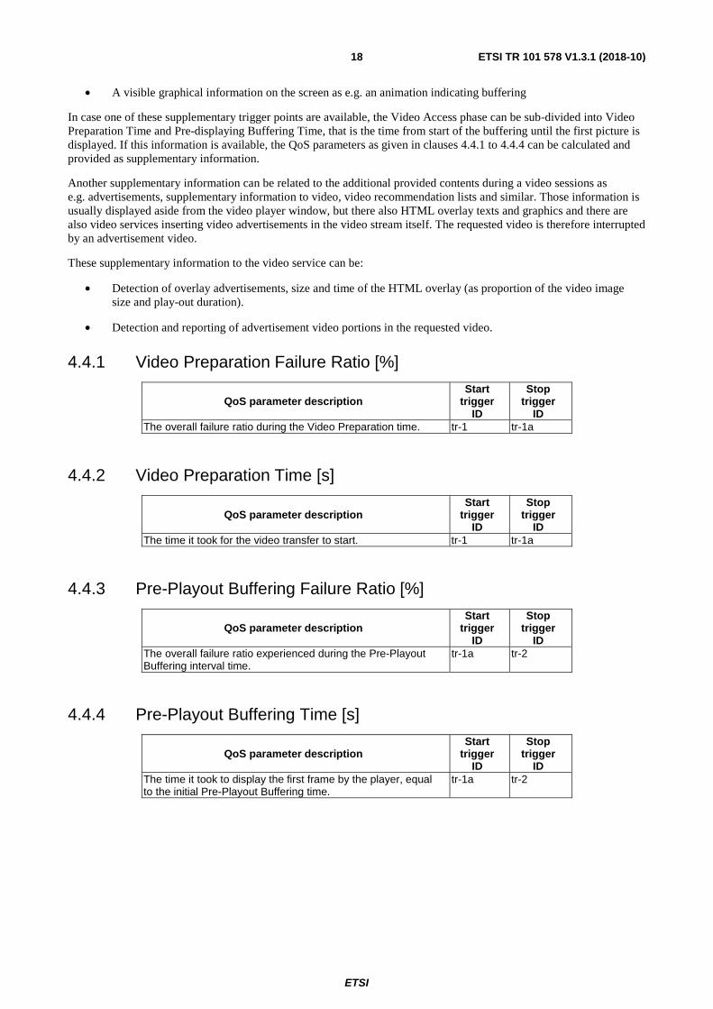
• A visible graphical information on the screen as e.g. an animation indicating buffering
In case one of these supplementary trigger points are available, the Video Access phase can be sub-divided into Video Preparation Time and Pre-displaying Buffering Time, that is the time from start of the buffering until the first picture is displayed. If this information is available, the QoS parameters as given in clauses 4.4.1 to 4.4.4 can be calculated and provided as supplementary information.
Another supplementary information can be related to the additional provided contents during a video sessions as e.g. advertisements, supplementary information to video, video recommendation lists and similar. Those information is usually displayed aside from the video player window, but there also HTML overlay texts and graphics and there are also video services inserting video advertisements in the video stream itself. The requested video is therefore interrupted by an advertisement video.
These supplementary information to the video service can be:
• Detection of overlay advertisements, size and time of the HTML overlay (as proportion of the video image size and play-out duration).
• Detection and reporting of advertisement video portions in the requested video.
4.4.1 Video Preparation Failure Ratio [%]
QoS parameter description Start
trigger ID
Stop trigger
ID The overall failure ratio during the Video Preparation time. tr-1 tr-1a
4.4.2 Video Preparation Time [s]
QoS parameter description Start
trigger ID
Stop trigger
ID The time it took for the video transfer to start. tr-1 tr-1a
4.4.3 Pre-Playout Buffering Failure Ratio [%]
QoS parameter description Start
trigger ID
Stop trigger
ID The overall failure ratio experienced during the Pre-Playout Buffering interval time.
tr-1a tr-2
4.4.4 Pre-Playout Buffering Time [s]
QoS parameter description Start
trigger ID
Stop trigger
ID The time it took to display the first frame by the player, equal to the initial Pre-Playout Buffering time.
tr-1a tr-2

ETSI
ETSI TR 101 578 V1.3.1 (2018-10) 19
4.5 Configuration aspects including timeout recommendations for IP-based video service measurements
4.5.0 Purpose
This clause gives examples for configuration options that can be used by active or manually tests to shape a YouTube™ measurement so it represents end-user experience more accurately.
4.5.1 URL
During video measurements, any traffic beyond the player and video download should be minimized as much as possible, which is why it is recommended to display videos using the full screen option of the video service application.
To avoid having to load the frontend with logos, thumbnail links to other videos, comments, etc. the direct link to the video has to be entered if possible. For e.g. YouTube™ is formed from the URL in the browser by replacing "/watch?v=<video ID>" and any additional parameters appended e.g. "&feature=related" with "/v/<video ID>" – with the video ID usually being an 11 character string, e.g. "eOjzLggAKis".
EXAMPLE 1: For a regular video link: http://www.youtube.com/watch?v=u1zgFlCw8Aw&feature=feedwll.
EXAMPLE 2: For corresponding full screen link: http://www.youtube.com/v/u1zgFlCw8Aw.
4.5.2 Timeouts
4.5.2.0 Application of timeouts
A range of timeouts and other thresholds can be used to:
a) derive QoS based on assumptions about the maximum tolerable degradations that a model user is willing to experience before aborting the service session; and
b) make automated video measurements more effective.
Some of these parameters can be derived from their counterparts for streaming services in the ETSI timeouts from ETSI TS 102 250-5 [i.2], which includes the following timeouts and recommendations: TBV
• Video Access Timeout (time to first picture) 60 s.
• Rebuffering Timeout (Single) 30 s.
• Rebuffering Timeout (Total) 75 % of session time.
• Max Allowed Rebuffering Frequency 20 rebuf/min.
In the following clauses, different measurement timeouts and suggestions regarding their length are explained.
4.5.2.1 Video Access timeout
The Video IP Service Access timeout determines how long the measurement engine will wait for the video to be displayed until the procedure is considered a failure. It can be considered as a maximum waiting time by a human user as well, for which he is willing to wait for starting the display of the video.
4.5.3 Video Playout Duration
The Video Playout Duration of the video tells the measurement engine the exact duration of the video in seconds, which is required for the calculation of related QoS parameters. It should be taken from the value that is displayed when the video is played manually. Measurements with videos of 90 s length are recommended which should be enough to show any problems that might occur. Savings in time and HDD space are significant with a shorter video duration and CPU load is greatly affected by video length as well.

ETSI
ETSI TR 101 578 V1.3.1 (2018-10) 20
4.5.4 Handling of video freezes
4.5.4.0 Use of freezes
Freezes in video playback can represent an important part of end-user experience and should be considered when creating a framework for measurements. The following parameters are suitable to control measurement execution and derive QoS based on assumptions about the maximum tolerable degradations that a model user is willing to experience before aborting the service session.
4.5.4.1 Minimum freeze duration
The minimum freeze duration is the minimum duration in milliseconds for a video to stall until it is recognized and evaluated as a freeze.
For example, if video is hidden during playout, hardware-related freezes in the worst case will be around 120 ms (with slow Hardware). In case video is displayed during playout hardware-related freezes in the worst case are around 280 ms. In comparison, actual network-related freezes are mostly bigger than 500 ms.
4.5.4.2 Maximum duration of single freeze
If a single freeze exceeds the maximum duration of single freeze value, the video download is evaluated as cut-off since a normal user would stop the video because the video got stuck. A typical user will be prepared to wait during one long rebuffering event. If one single interruption is longer than the timeout value, the playout phase is evaluated as cut-off.
4.5.4.3 Maximum duration of all freezes
If the sum of all freeze durations exceeds the maximum duration of all freezes value, the video download is evaluated as a cut-off. This reflects a regular user stopping the video because it got stuck too often in total.
4.5.4.4 Maximum number of freezes
A total number of maximum allowed freezes can be considered for use case configuration as well. This parameter is entirely subjective. The user may not be bothered with many short freezes when they are unnoticeably short and the video proceeds to play. On the other hand, someone who tries to listen to a song will be bothered even by short audio interruptions.
4.5.5 Timeout and Threshold Frameworks
The different types of timeouts and thresholds presented in the previous clauses constitute a framework of rules that models a user with specific properties, such as e.g.:
• Level of expectation/Comparable past experience.
• Level of patience/time pressure.
It needs to be understood that the setting of those parameters has immediate effect on the measured QoS parameter and hence any reporting of QoS parameter results needs to be always accompanied by the respective timeout and threshold settings applied during the related measurements.
Further, it may be wise not to change individual parameters without good reason but take into account how the different timeout mechanisms interact and always see a set of parameters as a "model" for a particular user type.
Table 3 presents examples settings and their rationales that do model a standard user and take into account technical boundary conditions.

ETSI
ETSI TR 101 578 V1.3.1 (2018-10) 21
Table 3: Example settings that do model a standard user
Timeout/Threshold Value [Unit] Comment/Rationale Video Access timeout 20 [s] This time out reflects the maximal time between requesting the
video and the first frame is displayed. It can be imagined as the maximum waiting patience of a user for the start of the video. In high-speed networks as LTE or HSPA, the Video Access Time is usually a few seconds, but to cover also other technologies and heavy-load situations in the networks, the timeout can be set to 15 to 20 s.
Minimum freeze duration 1.2 [s] A threshold of 1,2 s is recommended to recognize freezes caused by the network. Shorter freezes are usually caused by phone performance issues
Maximum duration of single freeze 15 [s] A value of 15 s is an acceptable best-practice value for an maximum accepted freezing event. It can also be seen as an indication for 'stream lost'. A user may stop watching the video in case the freeze exceeds 15 s. The video stream can be considered as 'lost' or 'dropped' in this case.
4.5.6 Hide video during playout
Hiding video playback during the playout phase will significantly reduce GPU and CPU load. This is especially recommended when connecting to a measurement system via remote desktop and the video would otherwise play back on the remote desktop machine. It needs to be ensured that the behaviour of the player or the device does not change if the video displaying is hidden. There are services requiring a foreground presentation to play the video. It can also be that hiding the video has different effects depending on presentation in landscape or portrait mode.
4.5.7 Play until the end
The video can be played back until the end even when the video download has already been completed. Omitting this step is recommended to save time during measurements, as video skips and interruptions only happen during download.
4.5.8 Cache and cookies
The cache should be cleared after measurement, which will delete the downloaded player and video files and prevent inadequate download times.
Today's video services also keep stored information about the last observed channel quality. This is mainly for starting a next video in an adequate quality (bitrate class). This information is usually only kept for a certain time (several ten seconds) and cleared afterwards and even updated in the background while the video information is not active. This will lead to an uncontrollable behaviour of the video application. Depending on the measurement timings, this stored information may be used or not. It is recommended to clear this information to ensure a start of the video application in a clean environment for each new measurement.
4.5.9 Video Resolution characteristics of the clip test
The video clip should be available to be played at high resolution too, avoiding to use videos that are available at low resolution only (like old YouTubeTM videos)
4.6 Impacts of measurement hardware for IP-based video service measurements
IP-based video services are, compared to e.g. a file download via FTP, much more demanding with respect to the CPU/GPU hardware requirements of the measurement system. Thus, special care should be taken when configuring a measurement system for such measurements.

ETSI
ETSI TR 101 578 V1.3.1 (2018-10) 22
Practical hints for performing measurements are:
• Adequate hardware should always be used to avoid effects of freezing and skipping to occur due to CPU/GPU overload.
• Hiding the video playout might help to decrease CPU/GPU load on systems with less powerful CPUs/GPUs.
• Operating the measurement system via a remote desktop connection is not advisable since this, even under optimal network conditions, can cause a lot of freezing because the video should appear on the remote desktop machine, causing also a very high CPU and GPU load and the related problems.

ETSI
ETSI TR 101 578 V1.3.1 (2018-10) 23
Annex A: Void

ETSI
ETSI TR 101 578 V1.3.1 (2018-10) 24
History
Document history
V1.1.1 December 2013 Publication
V1.2.1 July 2015 Publication
V1.3.1 October 2018 Publication