tps7b7702-q1 short circuit test report
TRANSCRIPT

1SLVAED0–February 2020Submit Documentation Feedback
Copyright © 2020, Texas Instruments Incorporated
TPS7B7702-Q1 Short Circuit Test Report
Application ReportSLVAED0–February 2020
TPS7B7702-Q1 Short Circuit Test Report
Application Engineer: Jason Song ....................................................................... Linear Regulator – LDO
ABSTRACTThe TPS7B770x-Q1 family of devices are single and dual high-voltage LDOs, with integrated thermalshutdown and short-circuit protection, in automotive systems. Therefore, the robustness of the deviceunder repetitive short-circuit stress is crucial for the entire system. The AEC Q100-012, which specifiesthe reliability of this type of device, is the most recognized qualification certificate in the industry.
The Automotive Electronics Council (AEC) provides the AEC Q100-012 documentation, which specifiesthe short-circuit reliability test. The main purpose of this test is to determine the reliability of smart-powerdevices operating in a continuous short-circuit condition.
Tests discussed in this report have been developed and performed according to the AEC-Q100-012 (REV-September 14-2006) document. 31 units have passed 300 000 cycles of cold repetitive short-pulse, coldrepetitive long-pulse, and hot repetitive tests. Pulses used in the tests are defined in the ATE-Q100-012document.
No failures (including gross and parametric) have been observed with the 31 units of the testedTPS7B7702-Q1 devices. According to the AEC-Q100-012, the TPS7B7702 has been rated Grade B after300000 cycles of stress.
Contents1 General Diagram for the Test Configuration ............................................................................. 22 Test Schematic and Materials Used ...................................................................................... 33 Test Flow...................................................................................................................... 44 Test Items and Test Results ............................................................................................... 4
List of Figures
1 Boards With 32 Sites in an Oven Connected Through an Edge Connector ......................................... 22 PCB Board With 32 Sites ................................................................................................... 23 Circuit Schematic for One Site ............................................................................................. 34 Zoomed-in View for One Site with Populated Components............................................................ 3
List of Tables
1 BOM From a Single Site .................................................................................................... 32 Test Items and Test Results ............................................................................................... 4
TrademarksAll trademarks are the property of their respective owners.

General Diagram for the Test Configuration www.ti.com
2 SLVAED0–February 2020Submit Documentation Feedback
Copyright © 2020, Texas Instruments Incorporated
TPS7B7702-Q1 Short Circuit Test Report
1 General Diagram for the Test ConfigurationFigure 2 shows the edge board with 32 sites in use. Figure 1 shows a general diagram of how the board isset up in the oven. To create the short-circuit condition, a FET has been used at each site to short Vout toground, which is being controlled with digital output (DI) channels from a Data-Acquisition-Card (NI USB-6363). An analog input (AI) channel has been used to measure the output of each individual site andcollect output voltage read points.
Figure 1. Boards With 32 Sites in an Oven Connected Through an Edge Connector
Figure 2. PCB Board With 32 Sites

1IN
EN2
NC3
VCC4
5SENSE
6NC
7NC
8SENSE_EN
ERR9
LIM10
NC11
GND12
NC13
NC14
FB15
OUT16
PAD17
U1
TPS7B7701QPWPRQ1
25VC1
10uF 25VC4
10uF
50V1uF
C2
50V1uF
C3
R110.2k
R210.2k
R310.2k
R4
10.2k
GND
GND
GND
GNDGND
GND
Vin
Vin
GND1
3
2,4 Q1FQT7N10LTF
GND
Vout
GND
5011
Vin
5010Vin
Signal1
Vout
ERR
ERR ERR
R510.2k
R610.2k
GND
GND
GND
www.ti.com Test Schematic and Materials Used
3SLVAED0–February 2020Submit Documentation Feedback
Copyright © 2020, Texas Instruments Incorporated
TPS7B7702-Q1 Short Circuit Test Report
2 Test Schematic and Materials UsedFigure 3 shows the schematic for a single site. The TPS7B7702-Q1 device is configured in switchedmode, and the output has a voltage divider to make the voltage lower than 10 V. This is so the analoginput channel can measure, as the analog input channel from the DAQ being used can only measure upto 10 V. Not everything has been populated for the actual board. Figure 4 shows the actual componentsthat have been mounted on the boards.
Figure 3. Circuit Schematic for One Site
Figure 4. Zoomed-in View for One Site with Populated Components
Table 1. BOM From a Single Site
Designator Value Manufacturer Package Reference Part NumberC1, C4 10 µF Taiyo Yuden 0805 TMK212BBJ106KG-TR5, R6 100 kΩ Yageo 0805 RC0805FR-07100KL
R1, R2, R4 0 Ω Vishay 0805 CRCW08050000ZSTA
Test Flow www.ti.com
4 SLVAED0–February 2020Submit Documentation Feedback
Copyright © 2020, Texas Instruments Incorporated
TPS7B7702-Q1 Short Circuit Test Report
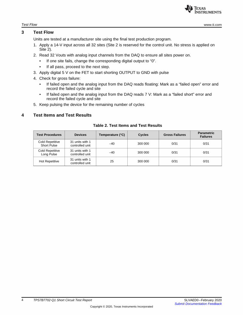
3 Test FlowUnits are tested at a manufacturer site using the final test production program.1. Apply a 14-V input across all 32 sites (Site 2 is reserved for the control unit. No stress is applied on
Site 2).2. Read 32 Vouts with analog input channels from the DAQ to ensure all sites power on.
• If one site fails, change the corresponding digital output to “0”.• If all pass, proceed to the next step.
3. Apply digital 5 V on the FET to start shorting OUTPUT to GND with pulse4. Check for gross failure:
• If failed open and the analog input from the DAQ reads floating: Mark as a “failed open” error andrecord the failed cycle and site
• If failed open and the analog input from the DAQ reads 7 V: Mark as a “failed short” error andrecord the failed cycle and site
5. Keep pulsing the device for the remaining number of cycles
4 Test Items and Test Results
Table 2. Test Items and Test Results
Test Procedures Devices Temperature (°C) Cycles Gross Failures ParametricFailures
Cold RepetitiveShort Pulse
31 units with 1controlled unit –40 300 000 0/31 0/31
Cold RepetitiveLong Pulse
31 units with 1controlled unit –40 300 000 0/31 0/31
Hot Repetitive 31 units with 1controlled unit 25 300 000 0/31 0/31

IMPORTANT NOTICE AND DISCLAIMER
TI PROVIDES TECHNICAL AND RELIABILITY DATA (INCLUDING DATASHEETS), DESIGN RESOURCES (INCLUDING REFERENCE DESIGNS), APPLICATION OR OTHER DESIGN ADVICE, WEB TOOLS, SAFETY INFORMATION, AND OTHER RESOURCES “AS IS” AND WITH ALL FAULTS, AND DISCLAIMS ALL WARRANTIES, EXPRESS AND IMPLIED, INCLUDING WITHOUT LIMITATION ANY IMPLIED WARRANTIES OF MERCHANTABILITY, FITNESS FOR A PARTICULAR PURPOSE OR NON-INFRINGEMENT OF THIRD PARTY INTELLECTUAL PROPERTY RIGHTS.These resources are intended for skilled developers designing with TI products. You are solely responsible for (1) selecting the appropriate TI products for your application, (2) designing, validating and testing your application, and (3) ensuring your application meets applicable standards, and any other safety, security, or other requirements. These resources are subject to change without notice. TI grants you permission to use these resources only for development of an application that uses the TI products described in the resource. Other reproduction and display of these resources is prohibited. No license is granted to any other TI intellectual property right or to any third party intellectual property right. TI disclaims responsibility for, and you will fully indemnify TI and its representatives against, any claims, damages, costs, losses, and liabilities arising out of your use of these resources.TI’s products are provided subject to TI’s Terms of Sale (www.ti.com/legal/termsofsale.html) or other applicable terms available either on ti.com or provided in conjunction with such TI products. TI’s provision of these resources does not expand or otherwise alter TI’s applicable warranties or warranty disclaimers for TI products.
Mailing Address: Texas Instruments, Post Office Box 655303, Dallas, Texas 75265Copyright © 2020, Texas Instruments Incorporated