tpeditor user manual - welcome to delta group user manual 2016-05-03 industrial automation...
TRANSCRIPT

www.deltaww.com
TPEditor User Manual
2016-05-03
Industrial Automation HeadquartersDelta Electronics, Inc. Taoyuan Technology CenterNo.18, Xinglong Rd., Taoyuan City, Taoyuan County 33068, TaiwanTEL: 886-3-362-6301 / FAX: 886-3-371-6301
AsiaDelta Electronics (Jiangsu) Ltd.Wujiang Plant 31688 Jiangxing East Road, Wujiang Economic Development ZoneWujiang City, Jiang Su Province, P.R.C. 215200TEL: 86-512-6340-3008 / FAX: 86-769-6340-7290
Delta Greentech (China) Co., Ltd.238 Min-Xia Road, Pudong District, ShangHai, P.R.C. 201209TEL: 86-21-58635678 / FAX: 86-21-58630003 Delta Electronics (Japan), Inc.Tokyo Office 2-1-14 Minato-ku Shibadaimon, Tokyo 105-0012, JapanTEL: 81-3-5733-1111 / FAX: 81-3-5733-1211
Delta Electronics (Korea), Inc.1511, Byucksan Digital Valley 6-cha, Gasan-dong, Geumcheon-gu, Seoul, Korea, 153-704TEL: 82-2-515-5303 / FAX: 82-2-515-5302
Delta Electronics Int’l (S) Pte Ltd.4 Kaki Bukit Ave 1, #05-05, Singapore 417939TEL: 65-6747-5155 / FAX: 65-6744-9228
Delta Electronics (India) Pvt. Ltd.Plot No 43 Sector 35, HSIIDC Gurgaon, PIN 122001, Haryana, India TEL : 91-124-4874900 / FAX : 91-124-4874945
AmericasDelta Products Corporation (USA)Raleigh OfficeP.O. Box 12173,5101 Davis Drive, Research Triangle Park, NC 27709, U.S.A.TEL: 1-919-767-3800 / FAX: 1-919-767-8080
Delta Greentech (Brasil) S.A.Sao Paulo OfficeRua Itapeva, 26 - 3° andar Edificio Itapeva One-Bela Vista01332-000-São Paulo-SP-BrazilTEL: 55 11 3568-3855 / FAX: 55 11 3568-3865
EuropeDeltronics (The Netherlands) B.V.Eindhoven OfficeDe Witbogt 15, 5652 AG Eindhoven, The Netherlands TEL: 31-40-2592850 / FAX: 31-40-2592851
TP-4949020-06
*We reserve the right to change the information in this manual without prior notice.
TPEditor User Manual
Revision History Version Revis ion Date
Firs t vers ion The f i rs t vers ion is publ ished. 2008/5/28
Second vers ion Chapter 1 and Chapter 3 are updated. 2013/9/30
Third vers ion
Al l chapters are rear ranged, and are updated accord ing to TPEdi to r. The in format ion re la ted to the new model TP70P is a lso added to the manual . (Please refer to sect ion 4 .1 .6, 4 .2.1, 4.2.2, 4.2 .3 , 4.2 .9 , 4 .2 .10, 4.2.11, 4.2 .12, 4.2.13, 4 .2.14 , 4.2.16, 4.2 .18, 4.2.20, 4 .2.21 , 5.1.8, 5.2.5 , 5.2 .11, Append ix A, and Append ix B for more in format ion about TP70P.)
2014/1/22
Four th vers ion
1. TP70P is changed to TP70. 2. The descr ip t ion of Ful l Screen and Refer Device
is de leted f rom sect ion 3 .3 . 3 . The descr ip t ion of the bu t tons used to add/de le te
a s ta te is added to sect ion 4.2.11, sect ion 4 .2.12 , and sect ion 4.2.14.
4. The descr ip t ion of the funct ions of the X-Y curves for TP70 ser ies tex t panels in sect ion 4.2.18 is updated.
5. Sect ion 4.2.22 and sect ion 4.2.23 are added. 6. The Funct ion Key Sett ing w indow in sect ion
5.1 .2 is updated. 7. Sect ion 5.2.12 is added. 8. Sect ion A.1 is updated.
2014/11/21
F i f th vers ion
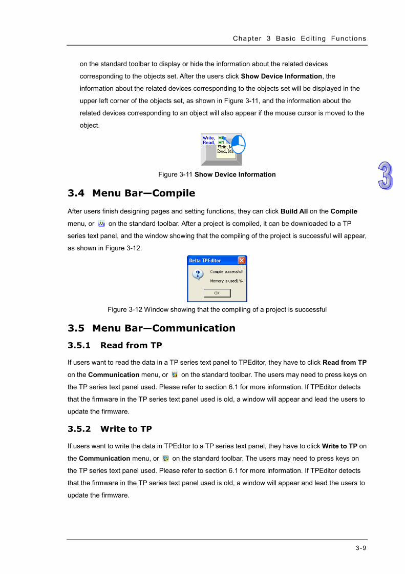
1. Show Device Informat ion is added to the View menu in sect ion 2.1.3, and the s tandard too lbar in sect ion 2.1 .4 .
2. Reset TP Memory (Factory Sett ing) is added to the Communicat ion menu in sect ion 2.1.3.
3. The Move Up bu t ton and the Move Down bu t ton are added to the Page Manager w indow in sect ion 3.3.
4. The descr ip t ion of Show Device Informat ion is added to sec t ion 3.3.
5. The descr ip t ion of the funct ion of updat ing f i rmware is added to sect ion 3 .5.
6. The descr ip t ion of Reset TP Memory (Factory Sett ing) is added to sect ion 3 .5.5.
7. In sect ion 4 .2.6, the image f i le format suppor ted is changed.
2015/4/13
Six th vers ion
1. Sect ion 2.1.4 added a new descr ipt ion of the objec t ar rangement toolbar.
2. Sect ion 3.1.1 added a new descr ipt ion of the buzzer and COM3.
3. The descr ip t ions of the Update Fi rmware Sett ing checkbox and the Enable PLC Core checkbox are added to sect ion 3.6.1. Sec t ion 3.6 .4 added a new descr ipt ion of System USB dr iver.
4. The descr ip t ion of the Dynamic Bitmap Set t ing
2016/05 /03

Version Revis ion Date window for TP70 ser ies tex t pane ls is added to sect ion 4.2.7.
5. The descr ip t ion of the Mult i -State Bitmap/Label Sett ing w indow for TP70 ser ies tex t pane ls in sect ion 4.2.14 is updated.
6. Sect ion 4.2.18 de letes descr ipt ion of TP70 ser ies . Sect ion 4.2.20 is updated.
7. Sect ion 4.2.21 and sect ion 4.2.22 are added to Chapter 4 .
8. Sect ion 5.2.5 is updated. 9. Table A-1 is updated.
i
TPEditor User Manual Contents
Chapter 1 Introduction of the Software 1.1 Introduction of TPEditor and System Requirements ................ 1-2
1.1.1 Characteristics ............................................................. 1-2 1.1.2 System Requirements ................................................... 1-2 1.1.3 Installing TPEditor ........................................................ 1-3 1.1.4 Uninstalling TPEditor ..................................................... 1-6
Chapter 2 Basic Introduction 2.1 Guide to Starting TPEditor and Introduction of the Environment 2-2
2.1.1 Starting TPEditor .......................................................... 2-2 2.1.2 Screen of TPEditor ........................................................ 2-3 2.1.3 Menu Bar .................................................................... 2-4 2.1.4 Toolbars ...................................................................... 2-8 2.1.5 Page Editing Area ......................................................... 2-9 2.1.6 Page Management Area ............................................... 2-12 2.1.7 Object Inspection Area ................................................ 2-12 2.1.8 Status Bar ................................................................. 2-13
Chapter 3 Basic Editing Functions 3.1 Menu Bar—File .................................................................. 3-2
3.1.1 New and Open File ....................................................... 3-2 3.1.2 Save and Save as ......................................................... 3-2 3.1.3 Print ........................................................................... 3-3 3.1.4 User Menu Setting ........................................................ 3-3 3.1.5 Page Property Outward to File ........................................ 3-6 3.1.6 Other Functions ........................................................... 3-6
3.2 Menu Bar—Edit .................................................................. 3-7 3.3 Menu Bar—View ................................................................ 3-8 3.4 Menu Bar—Compile ............................................................ 3-9 3.5 Menu Bar—Communication ................................................. 3-9
3.5.1 Read from TP ............................................................... 3-9 3.5.2 Write to TP .................................................................. 3-9 3.5.3 Write Boot Page to TP ................................................. 3-10 3.5.4 Write Menu to TP ....................................................... 3-10 3.5.5 Reset TP Memory (Factory Setting) ............................... 3-10
i i
3.6 Menu Bar—Tool ............................................................... 3-10 3.6.1 Basic Configuration .................................................... 3-10 3.6.2 Change TP Type ......................................................... 3-13 3.6.3 AutoSave Setup ......................................................... 3-14 3.6.4 Other Functions ......................................................... 3-15
3.7 Menu Bar—Window .......................................................... 3-15 3.8 Menu Bar—Help .............................................................. 3-16 Chapter 4 Setting Objects 4.1 Basic Setting Items ........................................................... 4-2
4.1.1 Setting Related Devices ................................................ 4-2 4.1.2 Setting Fonts ............................................................... 4-3 4.1.3 Setting the Appearances of Objects ................................ 4-4 4.1.4 Setting Numeric Objects ............................................... 4-6 4.1.5 Setting Buttons ........................................................... 4-6 4.1.6 Setting Locks .............................................................. 4-8
4.2 Descriptions of Objects ....................................................... 4-8 4.2.1 Geometric Graphic ....................................................... 4-8 4.2.2 Static Text .................................................................. 4-9 4.2.3 Numeric/ASCII Display ............................................... 4-11 4.2.4 Bit Lamp ................................................................... 4-12 4.2.5 Word Lamp ............................................................... 4-13 4.2.6 Static Bitmap ............................................................ 4-14 4.2.7 Dynamic Bitmap ........................................................ 4-15 4.2.8 Scale ........................................................................ 4-17 4.2.9 Bar Graph ................................................................. 4-18 4.2.10 Circle Meter .............................................................. 4-20 4.2.11 Message Display ........................................................ 4-23 4.2.12 Button ...................................................................... 4-27 4.2.13 RTC Display .............................................................. 4-47 4.2.14 Multi-State Bitmap/Label ............................................ 4-48 4.2.15 Units ........................................................................ 4-51 4.2.16 Numeric Input ........................................................... 4-51 4.2.17 Curve ....................................................................... 4-54 4.2.18 X-Y Curve ................................................................. 4-54 4.2.19 Delta Products Communication Device Setting ............... 4-55 4.2.20 Active Alarm List ........................................................ 4-57 4.2.21 Alarm History Table ................................................... 4-58
i i i
4.2.22 Alarm Moving Sign ..................................................... 4-59 4.2.23 Slider ....................................................................... 4-60 4.2.24 Input List .................................................................. 4-61 4.2.25 ComboBox ................................................................ 4-63
Chapter 5 Local Page Setting and Global Setting 5.1 Local Page Setting ............................................................. 5-2
5.1.1 Page Jump Condition Setting ......................................... 5-2 5.1.2 Function Key Setting ..................................................... 5-4 5.1.3 Alarm Buzzer Setting .................................................... 5-5 5.1.4 Alarm LED Setting ........................................................ 5-7 5.1.5 Write Page No. Setting .................................................. 5-8 5.1.6 Hide Page Setting ......................................................... 5-8 5.1.7 Local Macro Setting ...................................................... 5-9 5.1.8 Page Color Setting ...................................................... 5-12
5.2 Global Setting ................................................................. 5-12 5.2.1 User-Level Password Setting ........................................ 5-13 5.2.2 System Parameter Setting ........................................... 5-13 5.2.3 System Page Jump Setting .......................................... 5-16 5.2.4 System Function Key Setting ....................................... 5-16 5.2.5 System Alarm Buzzer Setting ....................................... 5-16 5.2.6 System Alarm LED Setting ........................................... 5-18 5.2.7 System RTC Setting .................................................... 5-18 5.2.8 System Power ON Setting ............................................ 5-19 5.2.9 Global Macro Setting................................................... 5-20 5.2.10 Recipe Setting ........................................................... 5-20 5.2.11 Default Page Color Setting ........................................... 5-23 5.2.12 User Re-define Direction Keys ...................................... 5-23
Chapter 6 Connection and Examples 6.1 Connection and Uploading/Downloading a Project ................... 6-2
6.1.1 Setting a Connection .................................................... 6-2 6.1.2 Downloading/Uploading a Project ................................... 6-3
6.2 Examples ......................................................................... 6-5 6.2.1 Example 1: Designing and Using a Boot Page ................... 6-5 6.2.2 Example 2: Connecting a TP Series Text Panel to a Delta PLC 6-9

i v
Appendix A Functions Supported by Models A.1 Objects Supported by Models .............................................. A-2 A.2 Button Types Supported by Models ...................................... A-3 A.3 Items Supported by Models on the Local Page Setting Menu .... A-4 A.4 Items Supported by Models on the Global Setting Menu .......... A-5 Appendix B USB Driver B.1 Installing a USB Driver ....................................................... B-2
1-1
Chapter 1 Introduction of the Software Contents 1.1 Introduction of TPEditor and System Requirements ................................. 1-2
1.1.1 Characteristics................................................................................... 1-2 1.1.2 System Requirements ....................................................................... 1-2 1.1.3 Installing TPEditor ............................................................................. 1-3 1.1.4 Uninstalling TPEditor ......................................................................... 1-6
TPEditor User Manual
1-2
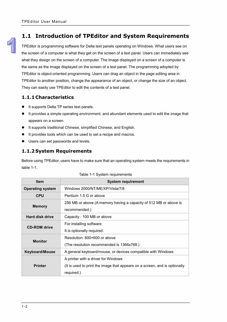
1.1 Introduction of TPEditor and System Requirements
TPEditor is programming software for Delta text panels operating on Windows. What users see on
the screen of a computer is what they get on the screen of a text panel. Users can immediately see
what they design on the screen of a computer. The image displayed on a screen of a computer is
the same as the image displayed on the screen of a text panel. The programming adopted by
TPEditor is object-oriented programming. Users can drag an object in the page editing area in
TPEditor to another position, change the appearance of an object, or change the size of an object.
They can easily use TPEditor to edit the contents of a text panel.
1.1.1 Characteristics
It supports Delta TP series text panels.
It provides a simple operating environment, and abundant elements used to edit the image that
appears on a screen.
It supports traditional Chinese, simplified Chinese, and English.
It provides tools which can be used to set a recipe and macros.
Users can set passwords and levels.
1.1.2 System Requirements
Before using TPEditor, users have to make sure that an operating system meets the requirements in
table 1-1.
Table 1-1 System requirements
Item System requirement
Operating system Windows 2000/NT/ME/XP/Vista/7/8
CPU Pentium 1.5 G or above
Memory 256 MB or above (A memory having a capacity of 512 MB or above is
recommended.)
Hard disk drive Capacity : 100 MB or above
CD-ROM drive For installing software
It is optionally required.
Monitor Resolution: 800×600 or above
(The resolution recommended is 1366x768.)
Keyboard/Mouse A general keyboard/mouse, or devices compatible with Windows
Printer
A printer with a driver for Windows
(It is used to print the image that appears on a screen, and is optionally
required.)
Chapter 1 Introduct ion of the Software
1-3
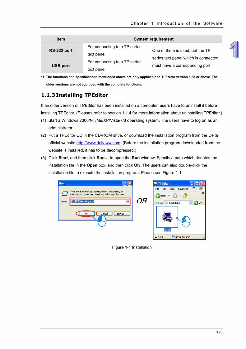
Item System requirement
RS-232 port For connecting to a TP series
text panel One of them is used, but the TP
series text panel which is connected
must have a corresponding port. USB port For connecting to a TP series
text panel
*1. The functions and specifications mentioned above are only applicable to TPEditor version 1.88 or above. The
older versions are not equipped with the complete functions.
1.1.3 Installing TPEditor
If an older version of TPEditor has been installed on a computer, users have to uninstall it before
installing TPEditor. (Pleases refer to section 1.1.4 for more information about uninstalling TPEditor.)
(1) Start a Windows 2000/NT/Me/XP/Vista/7/8 operating system. The users have to log on as an
administrator.
(2) Put a TPEditor CD in the CD-ROM drive, or download the installation program from the Delta
official website http://www.deltaww.com. (Before the installation program downloaded from the
website is installed, it has to be decompressed.)
(3) Click Start, and then click Run… to open the Run window. Specify a path which denotes the
installation file in the Open box, and then click OK. The users can also double-click the
installation file to execute the installation program. Please see Figure 1-1.
Figure 1-1 Installation
TPEditor User Manual
1-4
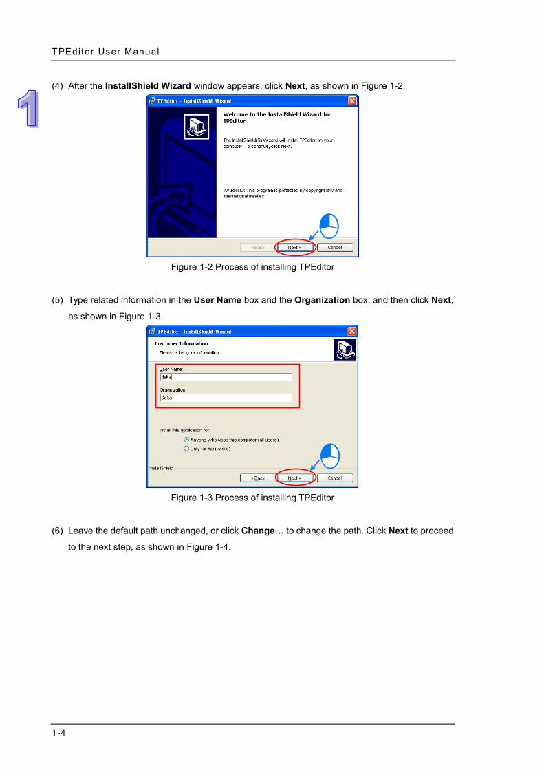
(4) After the InstallShield Wizard window appears, click Next, as shown in Figure 1-2.
Figure 1-2 Process of installing TPEditor
(5) Type related information in the User Name box and the Organization box, and then click Next,
as shown in Figure 1-3.
Figure 1-3 Process of installing TPEditor
(6) Leave the default path unchanged, or click Change… to change the path. Click Next to proceed
to the next step, as shown in Figure 1-4.
Chapter 1 Introduct ion of the Software
1-5
Figure 1-4 Process of installing TPEditor
(7) Check the installation information, and then click Install, as shown in Figure 1-5.
Figure 1-5 Process of installing TPEditor
(8) After TPEditor is installed, shortcuts to the program are created on the desktop and the Start
menu. Click Finish to complete the installation, as shown in Figure 1-6.
TPEditor User Manual
1-6
Figure 1-6 Completing the installation of TPEditor
1.1.4 Uninstalling TPEditor
(1) There are two methods of uninstalling TPEditor.
Method 1: Open the Control Panel window, and click Add or Remove Programs. In the
Currently installed programs box, click TPEditor x.xx, and then click Remove, as shown
in Figure 1-7.
Chapter 1 Introduct ion of the Software
1-7
Figure 1-7 Uninstalling TPEditor
Method 2: Start>Programs>Delta Industrial Automation>PLC>TPEditor x.xx>Uninstall
(Please see Figure 1-8.)
Figure 1-8 Uninstalling TPEditor
(2) After users click Yes, TPEditor will be removed, as shown in Figure 1-9.
Figure 1-9 Process of uninstalling TPEditor

TPEditor User Manual
1-8
MEMO
2-1
Chapter 2 Basic Introduction Contents 2.1 Guide to Starting TPEditor and Introduction of the Environment 2-2
2.1.1 Starting TPEditor ............................................................................ 2-2 2.1.2 Screen of TPEditor ......................................................................... 2-3 2.1.3 Menu Bar ......................................................................................... 2-4 2.1.4 Toolbars ........................................................................................... 2-8 2.1.5 Page Editing Area .......................................................................... 2-9 2.1.6 Page Management Area ...............................................................2-12 2.1.7 Object Inspection Area ................................................................2-12 2.1.8 Status Bar ......................................................................................2-13
TPEditor User Manual
2-2
2.1 Guide to Starting TPEditor and Introduction of the Environment
2.1.1 Starting TPEditor
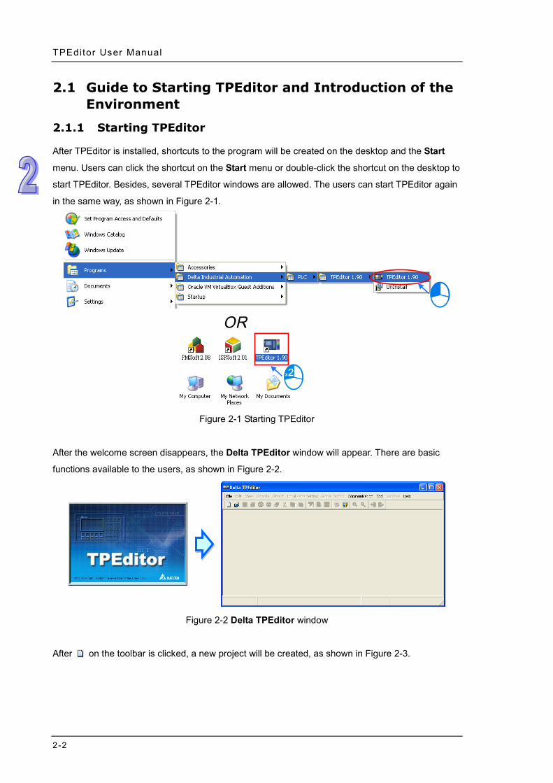
After TPEditor is installed, shortcuts to the program will be created on the desktop and the Start
menu. Users can click the shortcut on the Start menu or double-click the shortcut on the desktop to
start TPEditor. Besides, several TPEditor windows are allowed. The users can start TPEditor again
in the same way, as shown in Figure 2-1.
Figure 2-1 Starting TPEditor
After the welcome screen disappears, the Delta TPEditor window will appear. There are basic
functions available to the users, as shown in Figure 2-2.
Figure 2-2 Delta TPEditor window
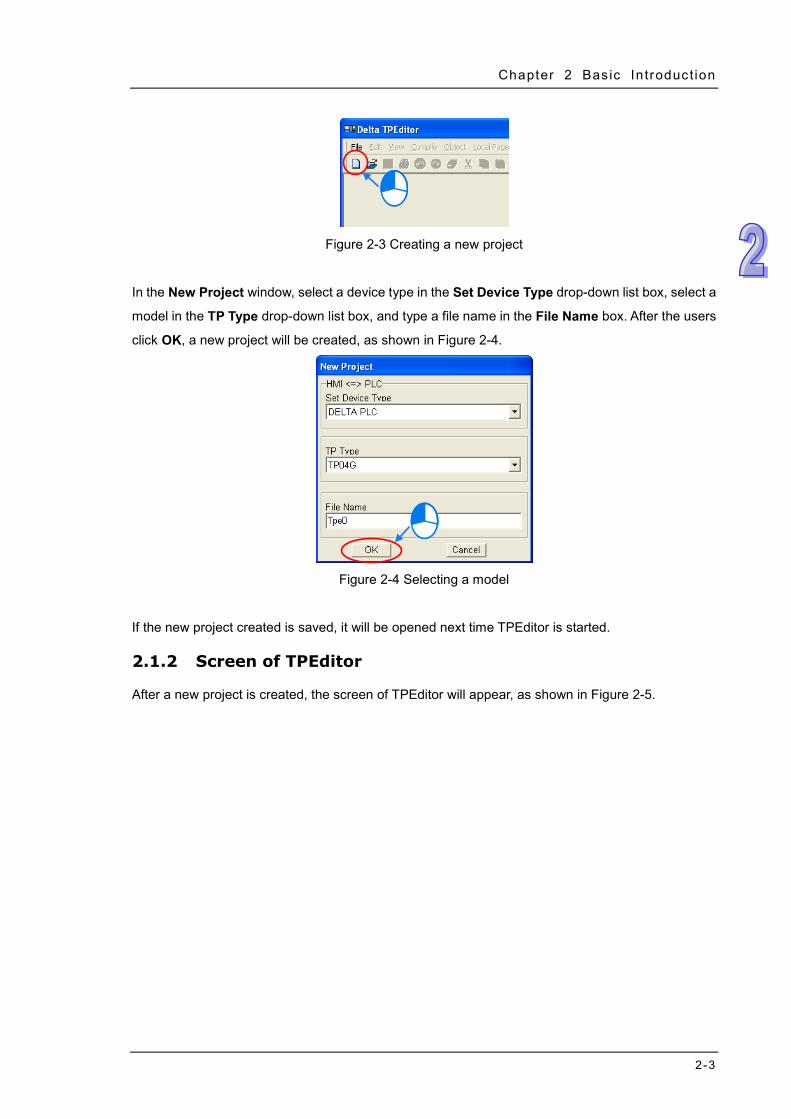
After on the toolbar is clicked, a new project will be created, as shown in Figure 2-3.
Chapter 2 Bas ic Introduct ion
2-3
Figure 2-3 Creating a new project
In the New Project window, select a device type in the Set Device Type drop-down list box, select a
model in the TP Type drop-down list box, and type a file name in the File Name box. After the users
click OK, a new project will be created, as shown in Figure 2-4.
Figure 2-4 Selecting a model
If the new project created is saved, it will be opened next time TPEditor is started.
2.1.2 Screen of TPEditor
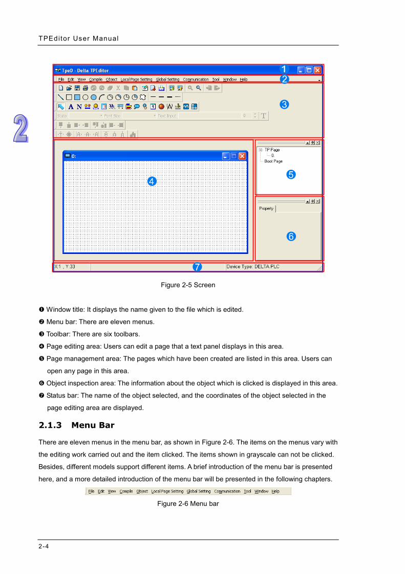
After a new project is created, the screen of TPEditor will appear, as shown in Figure 2-5.
TPEditor User Manual
2-4
Figure 2-5 Screen
Window title: It displays the name given to the file which is edited.
Menu bar: There are eleven menus.
Toolbar: There are six toolbars.
Page editing area: Users can edit a page that a text panel displays in this area.
Page management area: The pages which have been created are listed in this area. Users can
open any page in this area.
Object inspection area: The information about the object which is clicked is displayed in this area.
Status bar: The name of the object selected, and the coordinates of the object selected in the
page editing area are displayed.
2.1.3 Menu Bar
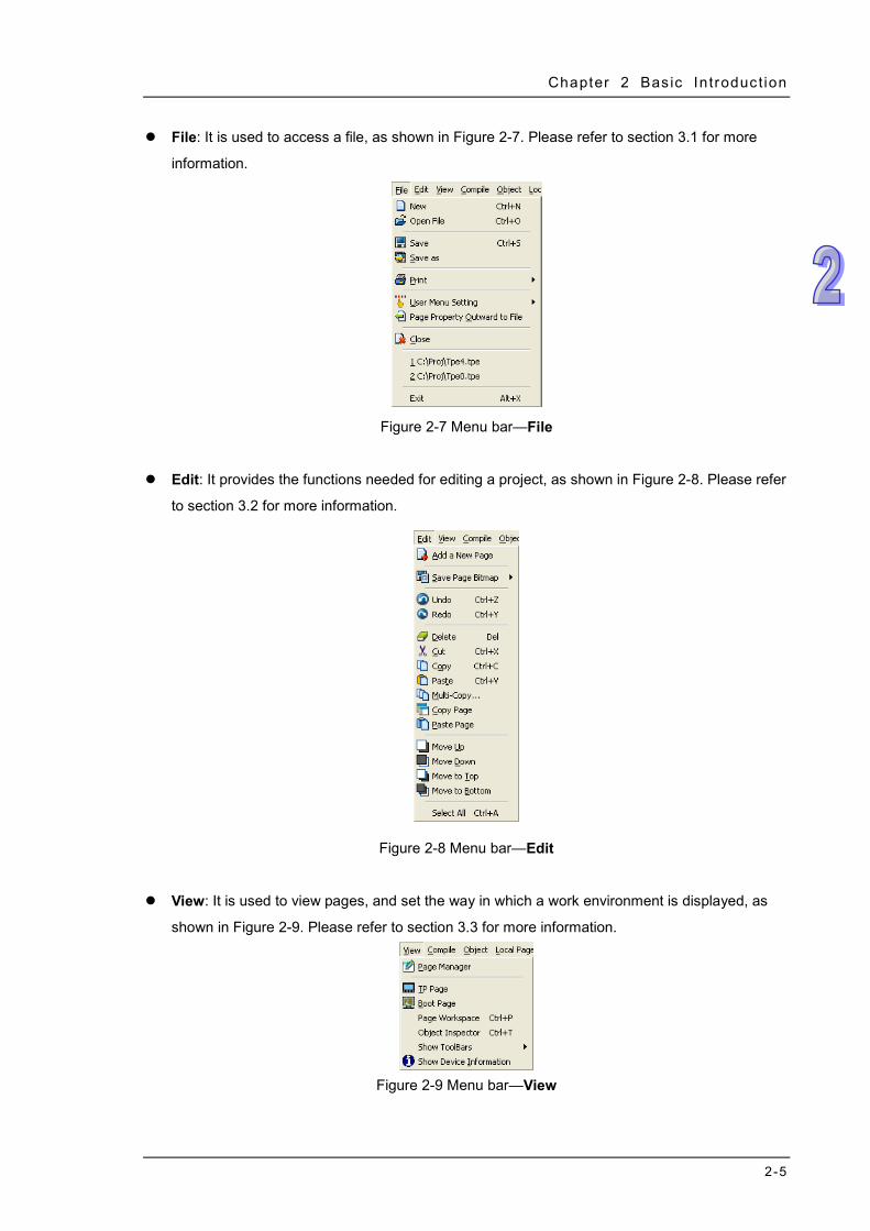
There are eleven menus in the menu bar, as shown in Figure 2-6. The items on the menus vary with
the editing work carried out and the item clicked. The items shown in grayscale can not be clicked.
Besides, different models support different items. A brief introduction of the menu bar is presented
here, and a more detailed introduction of the menu bar will be presented in the following chapters.
Figure 2-6 Menu bar
Chapter 2 Bas ic Introduct ion
2-5
File: It is used to access a file, as shown in Figure 2-7. Please refer to section 3.1 for more
information.
Figure 2-7 Menu bar—File
Edit: It provides the functions needed for editing a project, as shown in Figure 2-8. Please refer
to section 3.2 for more information.
Figure 2-8 Menu bar—Edit
View: It is used to view pages, and set the way in which a work environment is displayed, as
shown in Figure 2-9. Please refer to section 3.3 for more information.
Figure 2-9 Menu bar—View
TPEditor User Manual
2-6
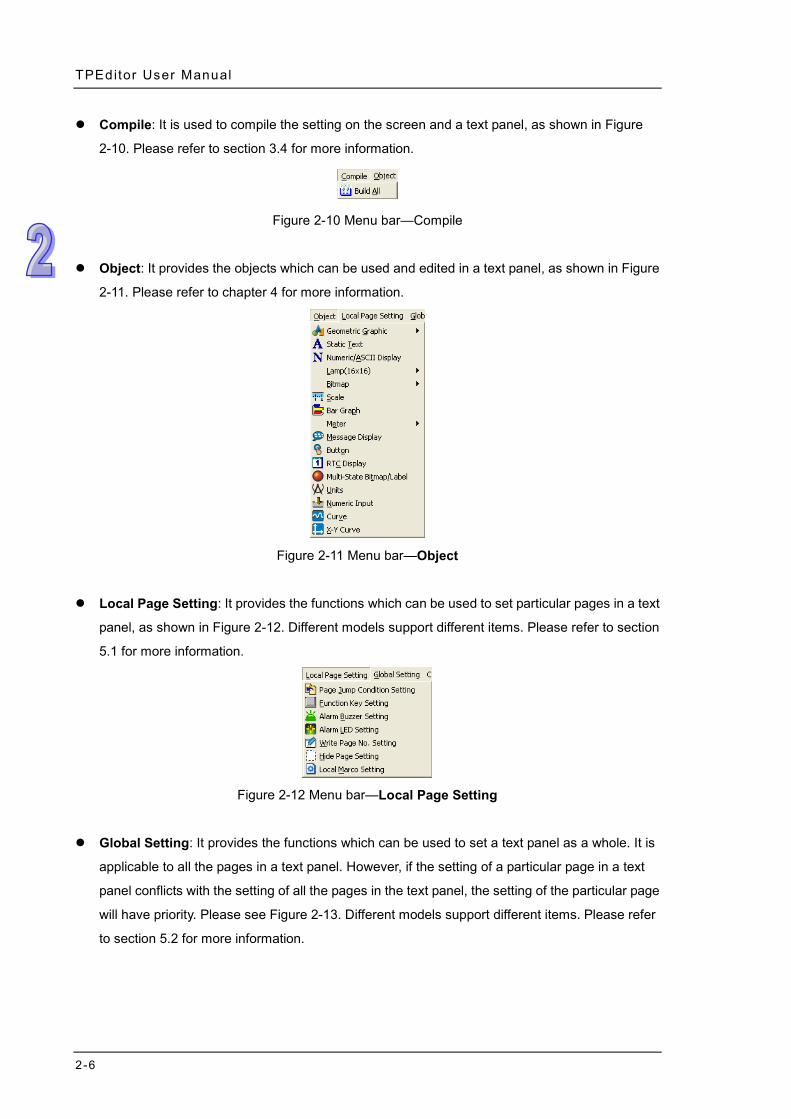
Compile: It is used to compile the setting on the screen and a text panel, as shown in Figure
2-10. Please refer to section 3.4 for more information.
Figure 2-10 Menu bar—Compile
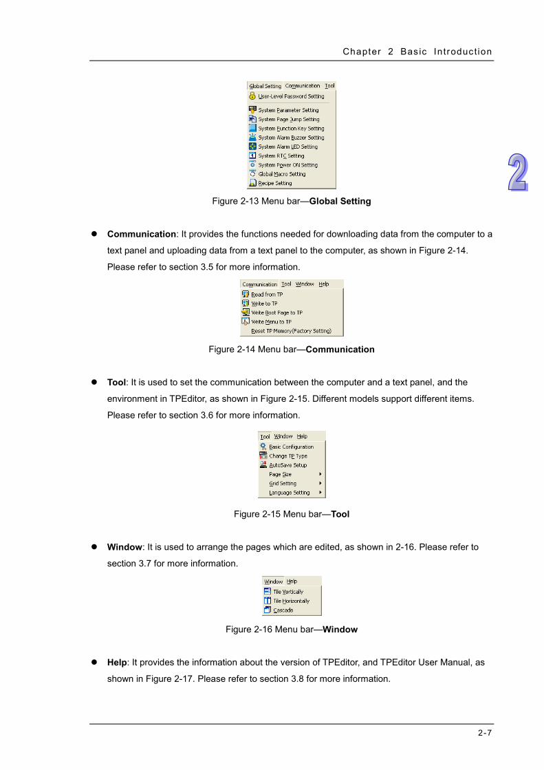
Object: It provides the objects which can be used and edited in a text panel, as shown in Figure
2-11. Please refer to chapter 4 for more information.
Figure 2-11 Menu bar—Object
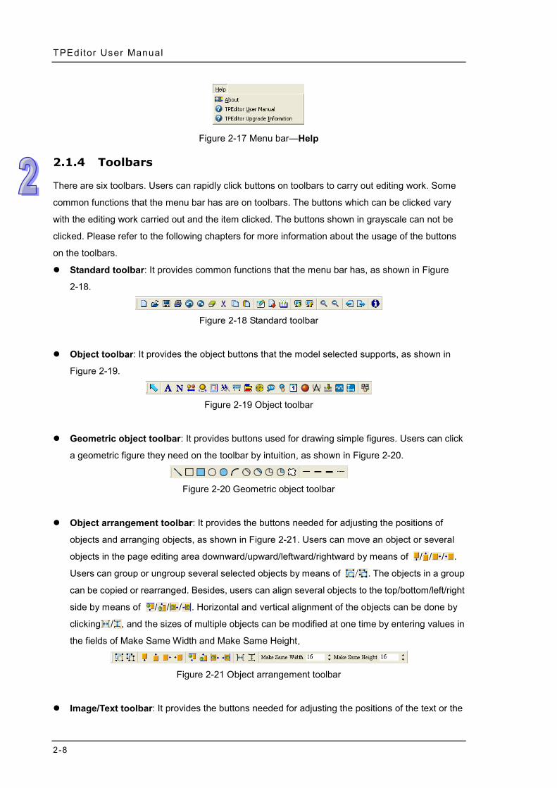
Local Page Setting: It provides the functions which can be used to set particular pages in a text
panel, as shown in Figure 2-12. Different models support different items. Please refer to section
5.1 for more information.
Figure 2-12 Menu bar—Local Page Setting
Global Setting: It provides the functions which can be used to set a text panel as a whole. It is
applicable to all the pages in a text panel. However, if the setting of a particular page in a text
panel conflicts with the setting of all the pages in the text panel, the setting of the particular page
will have priority. Please see Figure 2-13. Different models support different items. Please refer
to section 5.2 for more information.
Chapter 2 Bas ic Introduct ion
2-7
Figure 2-13 Menu bar—Global Setting
Communication: It provides the functions needed for downloading data from the computer to a
text panel and uploading data from a text panel to the computer, as shown in Figure 2-14.
Please refer to section 3.5 for more information.
Figure 2-14 Menu bar—Communication
Tool: It is used to set the communication between the computer and a text panel, and the
environment in TPEditor, as shown in Figure 2-15. Different models support different items.
Please refer to section 3.6 for more information.
Figure 2-15 Menu bar—Tool
Window: It is used to arrange the pages which are edited, as shown in 2-16. Please refer to
section 3.7 for more information.
Figure 2-16 Menu bar—Window
Help: It provides the information about the version of TPEditor, and TPEditor User Manual, as
shown in Figure 2-17. Please refer to section 3.8 for more information.
TPEditor User Manual
2-8
Figure 2-17 Menu bar—Help
2.1.4 Toolbars
There are six toolbars. Users can rapidly click buttons on toolbars to carry out editing work. Some
common functions that the menu bar has are on toolbars. The buttons which can be clicked vary
with the editing work carried out and the item clicked. The buttons shown in grayscale can not be
clicked. Please refer to the following chapters for more information about the usage of the buttons
on the toolbars.
Standard toolbar: It provides common functions that the menu bar has, as shown in Figure
2-18.
Figure 2-18 Standard toolbar
Object toolbar: It provides the object buttons that the model selected supports, as shown in
Figure 2-19.
Figure 2-19 Object toolbar
Geometric object toolbar: It provides buttons used for drawing simple figures. Users can click
a geometric figure they need on the toolbar by intuition, as shown in Figure 2-20.
Figure 2-20 Geometric object toolbar
Object arrangement toolbar: It provides the buttons needed for adjusting the positions of
objects and arranging objects, as shown in Figure 2-21. Users can move an object or several
objects in the page editing area downward/upward/leftward/rightward by means of / / / .
Users can group or ungroup several selected objects by means of / . The objects in a group
can be copied or rearranged. Besides, users can align several objects to the top/bottom/left/right
side by means of / / / . Horizontal and vertical alignment of the objects can be done by
clicking / , and the sizes of multiple objects can be modified at one time by entering values in
the fields of Make Same Width and Make Same Height.
Figure 2-21 Object arrangement toolbar
Image/Text toolbar: It provides the buttons needed for adjusting the positions of the text or the
Chapter 2 Bas ic Introduct ion
2-9
images in an object, and selecting an image file, as shown in Figure 2-22. After is clicked,
the text in an object can be moved. After is clicked, the images in an object can be moved.
After is clicked, an image file which has been saved can be opened. Users can horizontally
align the text or the images in an object left by means of , horizontally center the text or the
images in an object by means of , horizontally align the text or the images in an object right
by means of , vertically align the text or the images in an object up by means of , vertically
center the text or the images in an object by means of , and vertically align the text or the
images in an object down by means of .
Figure 2-22 Image/Text toolbar
Fast toolbar: It provides the functions needed for changing the state of an object, typing text,
and setting a font, as shown in Figure 2-23.
Figure 2-23 Fast toolbar
2.1.5 Page Editing Area
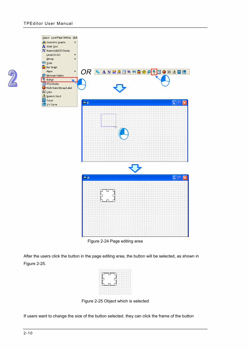
The page editing area is an area for designing or editing a page. It is the area which is displayed on
the screen of a text panel. After users click Button on the Object menu, or click Button on the
object toolbar, they can click where they want to begin the selection of an area in the page editing
area, hold down the left mouse button, and drag the cross over the area that they want to select, as
shown in Figure 2-24. A button will be inserted into the area selected after the users release the left
mouse button.
TPEditor User Manual
2-10
Figure 2-24 Page editing area
After the users click the button in the page editing area, the button will be selected, as shown in
Figure 2-25.
Figure 2-25 Object which is selected
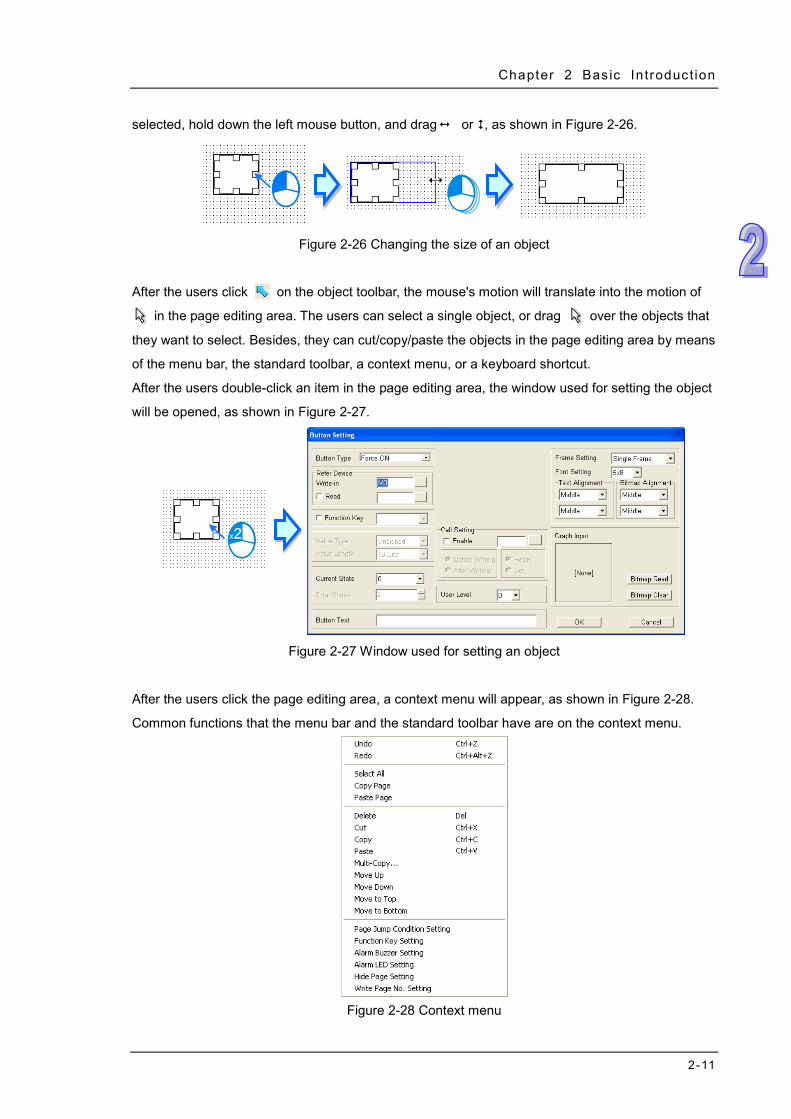
If users want to change the size of the button selected, they can click the frame of the button
Chapter 2 Bas ic Introduct ion
2-11
selected, hold down the left mouse button, and drag or , as shown in Figure 2-26.
Figure 2-26 Changing the size of an object
After the users click on the object toolbar, the mouse's motion will translate into the motion of
in the page editing area. The users can select a single object, or drag over the objects that
they want to select. Besides, they can cut/copy/paste the objects in the page editing area by means
of the menu bar, the standard toolbar, a context menu, or a keyboard shortcut.
After the users double-click an item in the page editing area, the window used for setting the object
will be opened, as shown in Figure 2-27.
Figure 2-27 Window used for setting an object
After the users click the page editing area, a context menu will appear, as shown in Figure 2-28.
Common functions that the menu bar and the standard toolbar have are on the context menu.
Figure 2-28 Context menu
TPEditor User Manual
2-12
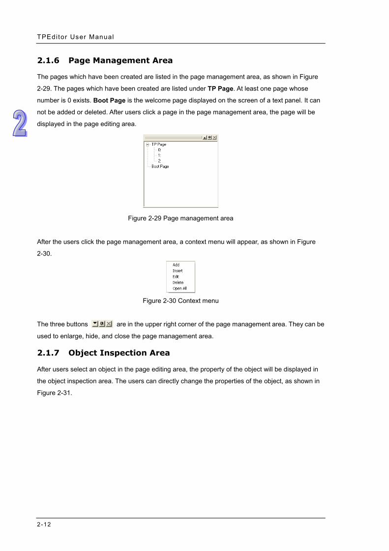
2.1.6 Page Management Area
The pages which have been created are listed in the page management area, as shown in Figure
2-29. The pages which have been created are listed under TP Page. At least one page whose
number is 0 exists. Boot Page is the welcome page displayed on the screen of a text panel. It can
not be added or deleted. After users click a page in the page management area, the page will be
displayed in the page editing area.
Figure 2-29 Page management area
After the users click the page management area, a context menu will appear, as shown in Figure
2-30.
Figure 2-30 Context menu
The three buttons are in the upper right corner of the page management area. They can be
used to enlarge, hide, and close the page management area.
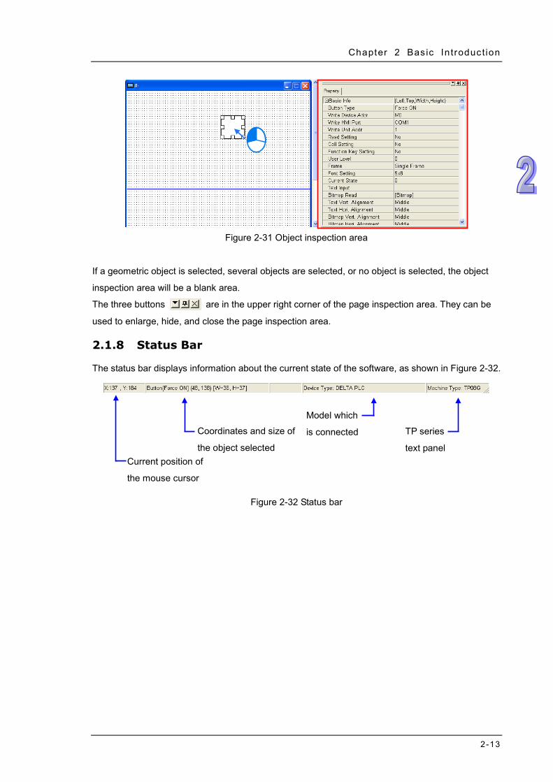
2.1.7 Object Inspection Area
After users select an object in the page editing area, the property of the object will be displayed in
the object inspection area. The users can directly change the properties of the object, as shown in
Figure 2-31.
Chapter 2 Bas ic Introduct ion
2-13
Figure 2-31 Object inspection area
If a geometric object is selected, several objects are selected, or no object is selected, the object
inspection area will be a blank area.
The three buttons are in the upper right corner of the page inspection area. They can be
used to enlarge, hide, and close the page inspection area.
2.1.8 Status Bar
The status bar displays information about the current state of the software, as shown in Figure 2-32.
Figure 2-32 Status bar
Model which
is connected
TP series
text panel
Coordinates and size of
the object selected Current position of
the mouse cursor

TPEditor User Manual
2-14
MEMO
3-1
Chapter 3 Basic Editing Functions Contents 3.1 Menu Bar—File....................................................................................... 3-2
3.1.1 New and Open File ........................................................................ 3-2 3.1.2 Save and Save as .......................................................................... 3-2 3.1.3 Print .................................................................................................. 3-3 3.1.4 User Menu Setting ......................................................................... 3-3 3.1.5 Page Property Outward to File .................................................... 3-6 3.1.6 Other Functions .............................................................................. 3-6
3.2 Menu Bar—Edit ...................................................................................... 3-7 3.3 Menu Bar—View .................................................................................... 3-8 3.4 Menu Bar—Compile .............................................................................. 3-9 3.5 Menu Bar—Communication ................................................................. 3-9
3.5.1 Read from TP .................................................................................. 3-9 3.5.2 Write to TP ...................................................................................... 3-9 3.5.3 Write Boot Page to TP ..................................................................3-10 3.5.4 Write Menu to TP ..........................................................................3-10 3.5.5 Reset TP Memory (Factory Setting) ..........................................3-10
3.6 Menu Bar—Tool ....................................................................................3-10 3.6.1 Basic Configuration ......................................................................3-10 3.6.2 Change TP Type ............................................................................3-13 3.6.3 AutoSave Setup ............................................................................3-14 3.6.4 Other Functions .............................................................................3-15
3.7 Menu Bar—Window ..............................................................................3-15 3.8 Menu Bar—Help ....................................................................................3-16
TPEditor User Manual
3-2
3.1 Menu Bar—File
3.1.1 New and Open File
If users want to create a new project, they have to click New on the File menu, or on the
standard toolbar. Please refer to section 2.1.1 for more information.
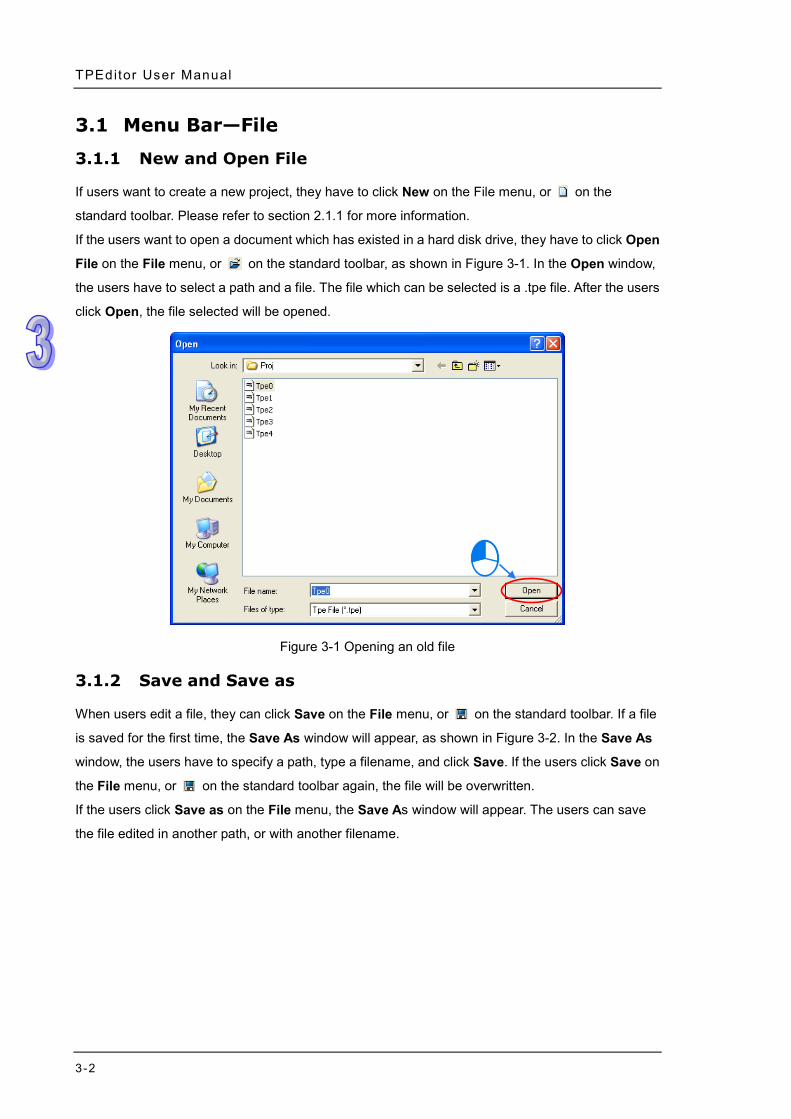
If the users want to open a document which has existed in a hard disk drive, they have to click Open
File on the File menu, or on the standard toolbar, as shown in Figure 3-1. In the Open window,
the users have to select a path and a file. The file which can be selected is a .tpe file. After the users
click Open, the file selected will be opened.
Figure 3-1 Opening an old file
3.1.2 Save and Save as
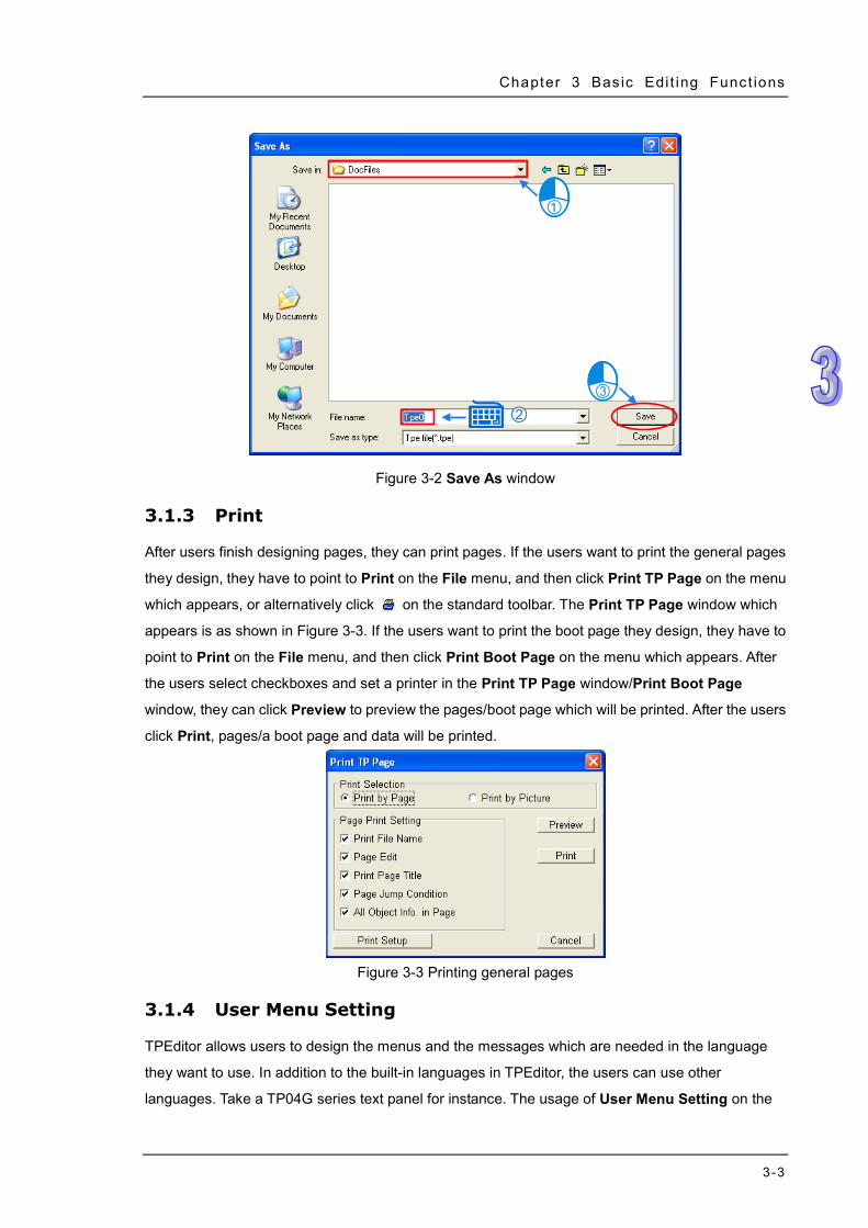
When users edit a file, they can click Save on the File menu, or on the standard toolbar. If a file
is saved for the first time, the Save As window will appear, as shown in Figure 3-2. In the Save As
window, the users have to specify a path, type a filename, and click Save. If the users click Save on
the File menu, or on the standard toolbar again, the file will be overwritten.
If the users click Save as on the File menu, the Save As window will appear. The users can save
the file edited in another path, or with another filename.
Chapter 3 Bas ic Edi t ing Funct ions
3-3
Figure 3-2 Save As window
3.1.3 Print
After users finish designing pages, they can print pages. If the users want to print the general pages
they design, they have to point to Print on the File menu, and then click Print TP Page on the menu
which appears, or alternatively click on the standard toolbar. The Print TP Page window which
appears is as shown in Figure 3-3. If the users want to print the boot page they design, they have to
point to Print on the File menu, and then click Print Boot Page on the menu which appears. After
the users select checkboxes and set a printer in the Print TP Page window/Print Boot Page
window, they can click Preview to preview the pages/boot page which will be printed. After the users
click Print, pages/a boot page and data will be printed.
Figure 3-3 Printing general pages
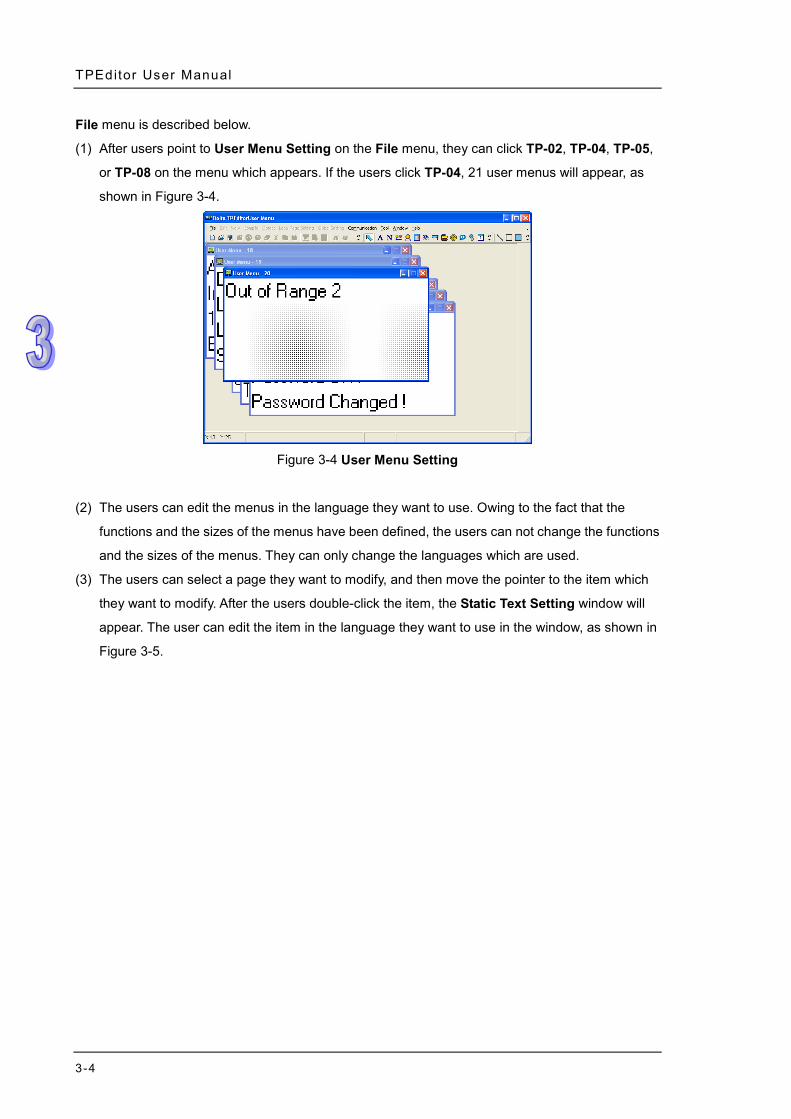
3.1.4 User Menu Setting
TPEditor allows users to design the menus and the messages which are needed in the language
they want to use. In addition to the built-in languages in TPEditor, the users can use other
languages. Take a TP04G series text panel for instance. The usage of User Menu Setting on the
TPEditor User Manual
3-4
File menu is described below.
(1) After users point to User Menu Setting on the File menu, they can click TP-02, TP-04, TP-05,
or TP-08 on the menu which appears. If the users click TP-04, 21 user menus will appear, as
shown in Figure 3-4.
Figure 3-4 User Menu Setting
(2) The users can edit the menus in the language they want to use. Owing to the fact that the
functions and the sizes of the menus have been defined, the users can not change the functions
and the sizes of the menus. They can only change the languages which are used.
(3) The users can select a page they want to modify, and then move the pointer to the item which
they want to modify. After the users double-click the item, the Static Text Setting window will
appear. The user can edit the item in the language they want to use in the window, as shown in
Figure 3-5.
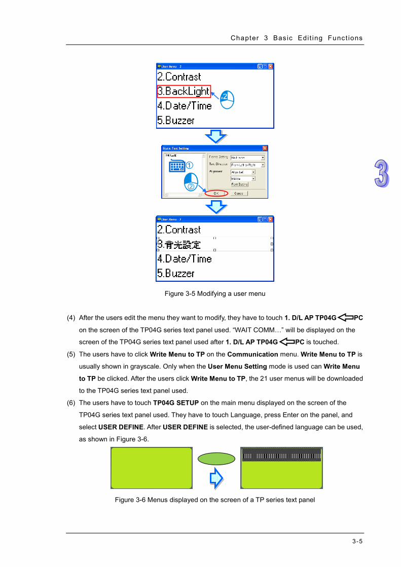
Chapter 3 Bas ic Edi t ing Funct ions
3-5
Figure 3-5 Modifying a user menu
(4) After the users edit the menu they want to modify, they have to touch 1. D/L AP TP04G PC
on the screen of the TP04G series text panel used. “WAIT COMM…” will be displayed on the
screen of the TP04G series text panel used after 1. D/L AP TP04G PC is touched.
(5) The users have to click Write Menu to TP on the Communication menu. Write Menu to TP is
usually shown in grayscale. Only when the User Menu Setting mode is used can Write Menu
to TP be clicked. After the users click Write Menu to TP, the 21 user menus will be downloaded
to the TP04G series text panel used.
(6) The users have to touch TP04G SETUP on the main menu displayed on the screen of the
TP04G series text panel used. They have to touch Language, press Enter on the panel, and
select USER DEFINE. After USER DEFINE is selected, the user-defined language can be used,
as shown in Figure 3-6.
Figure 3-6 Menus displayed on the screen of a TP series text panel
TPEditor User Manual
3-6
3.1.5 Page Property Outward to File
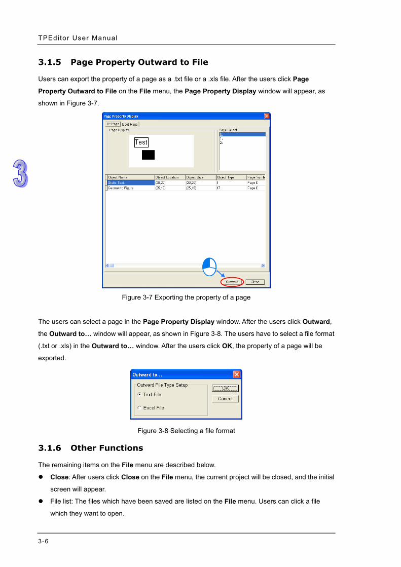
Users can export the property of a page as a .txt file or a .xls file. After the users click Page
Property Outward to File on the File menu, the Page Property Display window will appear, as
shown in Figure 3-7.
Figure 3-7 Exporting the property of a page
The users can select a page in the Page Property Display window. After the users click Outward,
the Outward to… window will appear, as shown in Figure 3-8. The users have to select a file format
(.txt or .xls) in the Outward to… window. After the users click OK, the property of a page will be
exported.
Figure 3-8 Selecting a file format
3.1.6 Other Functions
The remaining items on the File menu are described below.
Close: After users click Close on the File menu, the current project will be closed, and the initial
screen will appear.
File list: The files which have been saved are listed on the File menu. Users can click a file
which they want to open.
Chapter 3 Bas ic Edi t ing Funct ions
3-7
Exit: After users click Exit on the File menu, TPEditor will be closed.
3.2 Menu Bar—Edit
The items on the Edit menu are described below.
Add a New Page: After users click Add a New Page on the File menu, or on the standard
toolbar, a new page will be added to the page editing area.
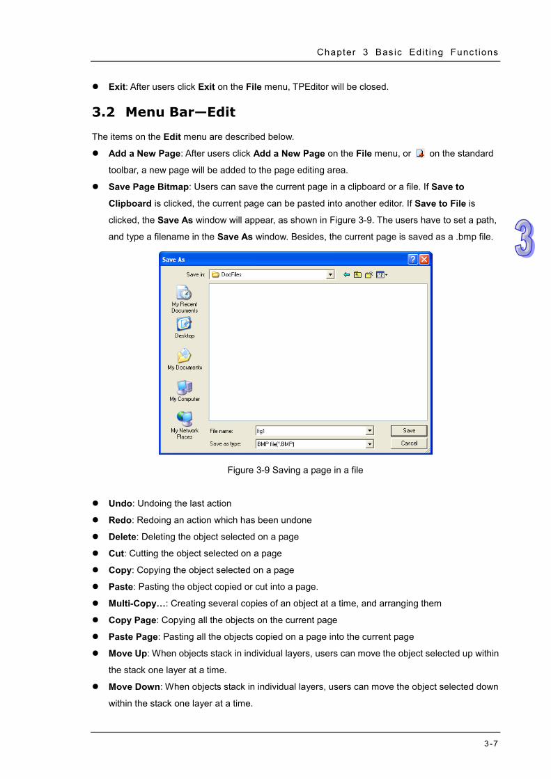
Save Page Bitmap: Users can save the current page in a clipboard or a file. If Save to
Clipboard is clicked, the current page can be pasted into another editor. If Save to File is
clicked, the Save As window will appear, as shown in Figure 3-9. The users have to set a path,
and type a filename in the Save As window. Besides, the current page is saved as a .bmp file.
Figure 3-9 Saving a page in a file
Undo: Undoing the last action
Redo: Redoing an action which has been undone
Delete: Deleting the object selected on a page
Cut: Cutting the object selected on a page
Copy: Copying the object selected on a page
Paste: Pasting the object copied or cut into a page.
Multi-Copy…: Creating several copies of an object at a time, and arranging them
Copy Page: Copying all the objects on the current page
Paste Page: Pasting all the objects copied on a page into the current page
Move Up: When objects stack in individual layers, users can move the object selected up within
the stack one layer at a time.
Move Down: When objects stack in individual layers, users can move the object selected down
within the stack one layer at a time.
TPEditor User Manual
3-8
Move to Top: When objects stack in individual layers, users can move the object selected to the
top of the stack in one move.
Move to Bottom: When objects stack in individual layers, users can move the object selected to
the bottom of the stack in one move.
Select All: Selecting all the objects on the current page.
3.3 Menu Bar—View
The items on the View menu are described below.
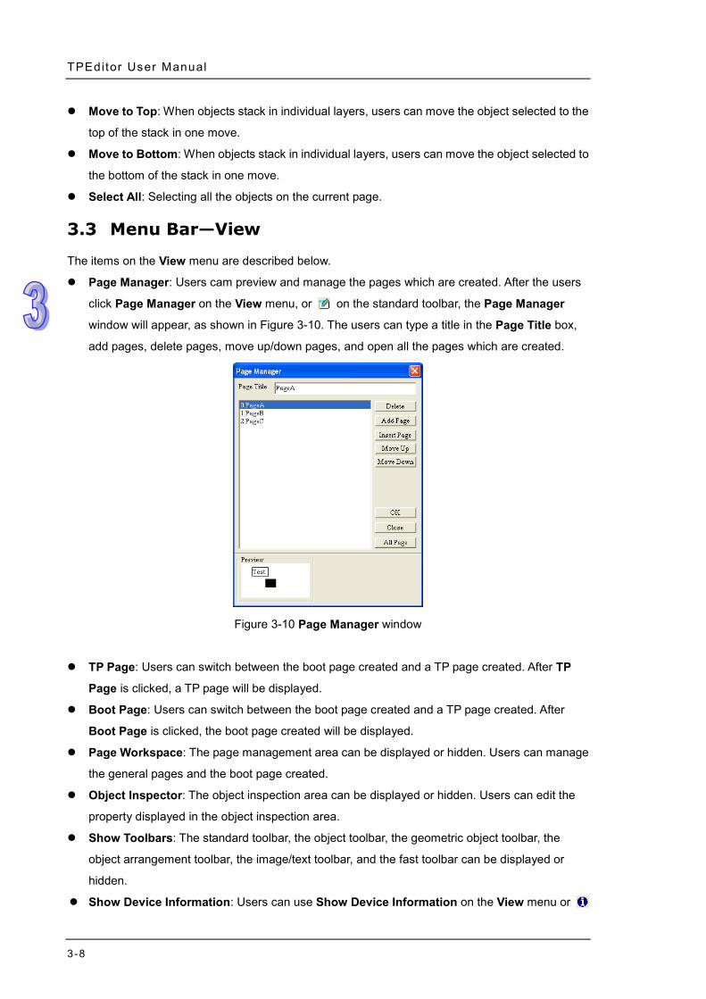
Page Manager: Users cam preview and manage the pages which are created. After the users
click Page Manager on the View menu, or on the standard toolbar, the Page Manager
window will appear, as shown in Figure 3-10. The users can type a title in the Page Title box,
add pages, delete pages, move up/down pages, and open all the pages which are created.
Figure 3-10 Page Manager window
TP Page: Users can switch between the boot page created and a TP page created. After TP
Page is clicked, a TP page will be displayed.
Boot Page: Users can switch between the boot page created and a TP page created. After
Boot Page is clicked, the boot page created will be displayed.
Page Workspace: The page management area can be displayed or hidden. Users can manage
the general pages and the boot page created.
Object Inspector: The object inspection area can be displayed or hidden. Users can edit the
property displayed in the object inspection area.
Show Toolbars: The standard toolbar, the object toolbar, the geometric object toolbar, the
object arrangement toolbar, the image/text toolbar, and the fast toolbar can be displayed or
hidden.
Show Device Information: Users can use Show Device Information on the View menu or
Chapter 3 Bas ic Edi t ing Funct ions
3-9
on the standard toolbar to display or hide the information about the related devices
corresponding to the objects set. After the users click Show Device Information, the
information about the related devices corresponding to the objects set will be displayed in the
upper left corner of the objects set, as shown in Figure 3-11, and the information about the
related devices corresponding to an object will also appear if the mouse cursor is moved to the
object.
Figure 3-11 Show Device Information
3.4 Menu Bar—Compile
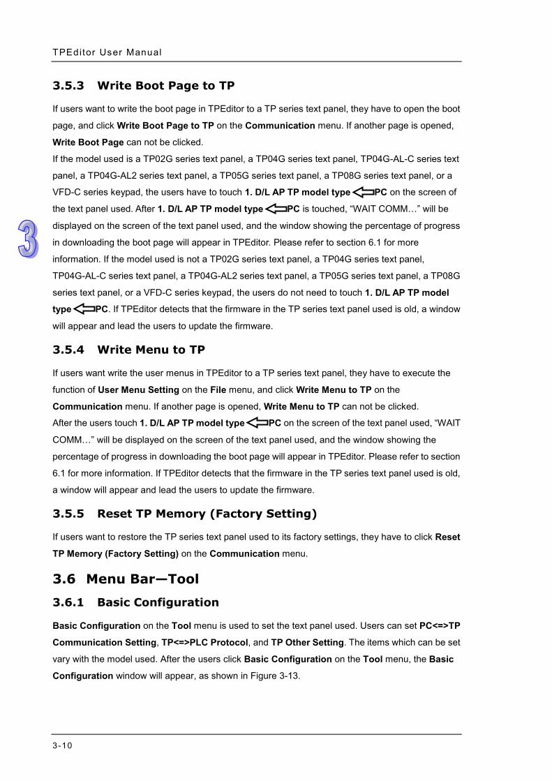
After users finish designing pages and setting functions, they can click Build All on the Compile
menu, or on the standard toolbar. After a project is compiled, it can be downloaded to a TP
series text panel, and the window showing that the compiling of the project is successful will appear,
as shown in Figure 3-12.
Figure 3-12 Window showing that the compiling of a project is successful
3.5 Menu Bar—Communication
3.5.1 Read from TP
If users want to read the data in a TP series text panel to TPEditor, they have to click Read from TP
on the Communication menu, or on the standard toolbar. The users may need to press keys on
the TP series text panel used. Please refer to section 6.1 for more information. If TPEditor detects
that the firmware in the TP series text panel used is old, a window will appear and lead the users to
update the firmware.
3.5.2 Write to TP
If users want to write the data in TPEditor to a TP series text panel, they have to click Write to TP on
the Communication menu, or on the standard toolbar. The users may need to press keys on
the TP series text panel used. Please refer to section 6.1 for more information. If TPEditor detects
that the firmware in the TP series text panel used is old, a window will appear and lead the users to
update the firmware.
TPEditor User Manual
3-10
3.5.3 Write Boot Page to TP
If users want to write the boot page in TPEditor to a TP series text panel, they have to open the boot
page, and click Write Boot Page to TP on the Communication menu. If another page is opened,
Write Boot Page can not be clicked.
If the model used is a TP02G series text panel, a TP04G series text panel, TP04G-AL-C series text
panel, a TP04G-AL2 series text panel, a TP05G series text panel, a TP08G series text panel, or a
VFD-C series keypad, the users have to touch 1. D/L AP TP model type PC on the screen of
the text panel used. After 1. D/L AP TP model type PC is touched, “WAIT COMM…” will be
displayed on the screen of the text panel used, and the window showing the percentage of progress
in downloading the boot page will appear in TPEditor. Please refer to section 6.1 for more
information. If the model used is not a TP02G series text panel, a TP04G series text panel,
TP04G-AL-C series text panel, a TP04G-AL2 series text panel, a TP05G series text panel, a TP08G
series text panel, or a VFD-C series keypad, the users do not need to touch 1. D/L AP TP model
type PC. If TPEditor detects that the firmware in the TP series text panel used is old, a window
will appear and lead the users to update the firmware.
3.5.4 Write Menu to TP
If users want write the user menus in TPEditor to a TP series text panel, they have to execute the
function of User Menu Setting on the File menu, and click Write Menu to TP on the
Communication menu. If another page is opened, Write Menu to TP can not be clicked.
After the users touch 1. D/L AP TP model type PC on the screen of the text panel used, “WAIT
COMM…” will be displayed on the screen of the text panel used, and the window showing the
percentage of progress in downloading the boot page will appear in TPEditor. Please refer to section
6.1 for more information. If TPEditor detects that the firmware in the TP series text panel used is old,
a window will appear and lead the users to update the firmware.
3.5.5 Reset TP Memory (Factory Setting)
If users want to restore the TP series text panel used to its factory settings, they have to click Reset
TP Memory (Factory Setting) on the Communication menu.
3.6 Menu Bar—Tool
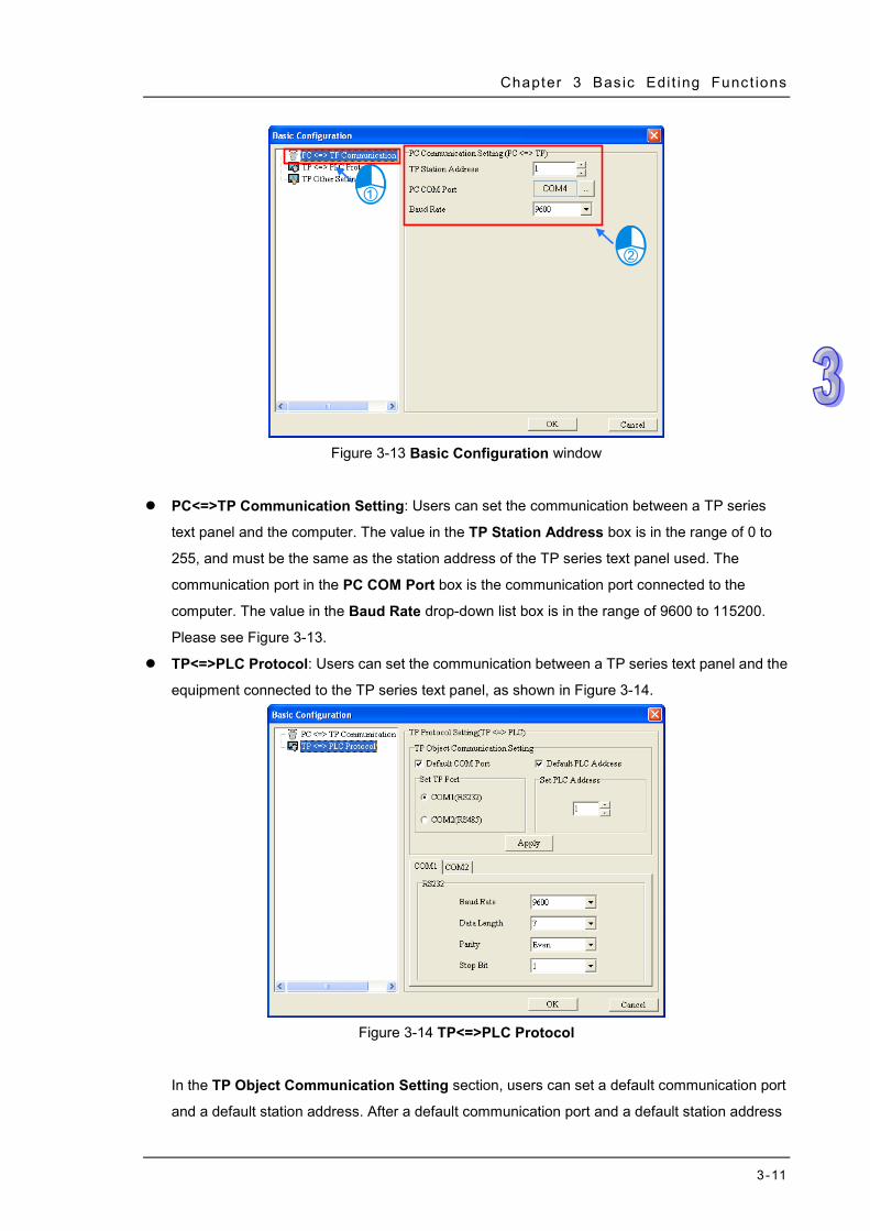
3.6.1 Basic Configuration
Basic Configuration on the Tool menu is used to set the text panel used. Users can set PC<=>TP
Communication Setting, TP<=>PLC Protocol, and TP Other Setting. The items which can be set
vary with the model used. After the users click Basic Configuration on the Tool menu, the Basic
Configuration window will appear, as shown in Figure 3-13.
Chapter 3 Bas ic Edi t ing Funct ions
3-11
Figure 3-13 Basic Configuration window
PC<=>TP Communication Setting: Users can set the communication between a TP series
text panel and the computer. The value in the TP Station Address box is in the range of 0 to
255, and must be the same as the station address of the TP series text panel used. The
communication port in the PC COM Port box is the communication port connected to the
computer. The value in the Baud Rate drop-down list box is in the range of 9600 to 115200.
Please see Figure 3-13.
TP<=>PLC Protocol: Users can set the communication between a TP series text panel and the
equipment connected to the TP series text panel, as shown in Figure 3-14.
Figure 3-14 TP<=>PLC Protocol
In the TP Object Communication Setting section, users can set a default communication port
and a default station address. After a default communication port and a default station address
TPEditor User Manual
3-12
are set, the communication address and the station address in the Refer Device window will be
the default communication port and the default station address. Please refer to section 4.1.1 for
more information. The communication parameters of the TP series text panel used must be the
same as the communication parameters of the equipment connected to the TP series text panel
used.
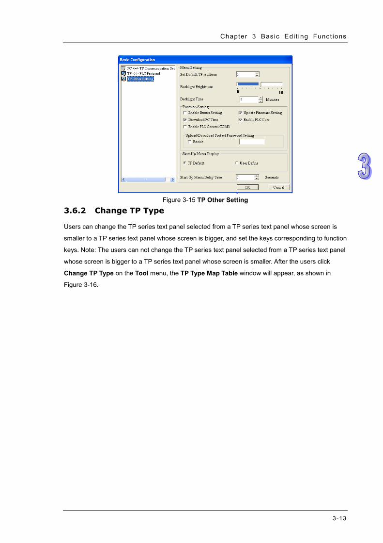
TP Other Setting: Users can set the hardware of the TP series text panel used, such as the
station address of the TP series text panel used, and the brightness of the backlight that
illuminates the screen of the TP series text panel used. The functions supported vary with the
model used. If the users select a value in the Backlight Setting box, the backlight that
illuminates the screen of the TP series text panel used will last for the time set. If the value
selected in the Backlight Setting box is 0, a backlight will always illuminate the screen of the
TP series text panel used. The buzzer will be enabled after the Enable Buzzer Setting is
selected. If the Download PC Time checkbox is selected, the time of the clock in the computer
will be downloaded to the real-time clock in the TP series text panel used. After the Update
Firmware Setting checkbox is selected, a dialog box which leads the users to update the
firmware in the TP series text panel used will appear if TPEditor detects that the firmware in the
text panel is old when the program in TPEditor is downloaded to the text panel or the program in
the text panel is uploaded to TPEditor. If the Enable PLC Core checkbox is selected, the PLC in
the TP series text panel used will be enabled. If the Enable PLC Core checkbox is unselected,
the PLC in the TP series text panel used will be disabled, system resources will be saved, and
the screen of the text panel will be updated more rapidly. When users select Enable PLC
Control COM3, COM3 will be occupied by internal PLC core, otherwise COM3 will belong to TP
for communication. If the users select the Enable checkbox in the Upload/Download Protect
Password Setting section, and type a password, they are asked to type the password when
they upload/download the project created. In the Start-Up Menu Display section, the users can
select the TP Default checkbox, or the User Define checkbox. The users can set the time for
which the boot screen selected lasts. Please see Figure 3-15.
Chapter 3 Bas ic Edi t ing Funct ions
3-13
Figure 3-15 TP Other Setting 3.6.2 Change TP Type
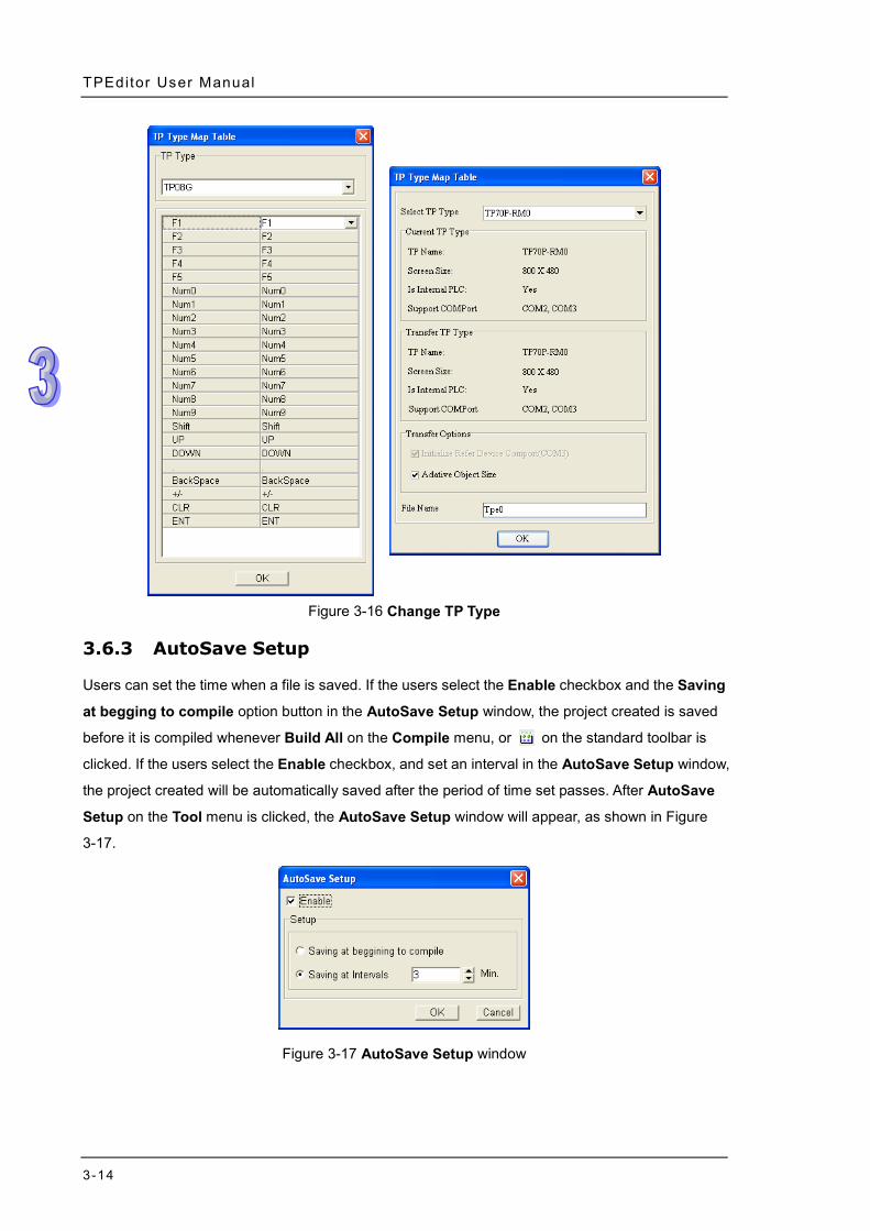
Users can change the TP series text panel selected from a TP series text panel whose screen is
smaller to a TP series text panel whose screen is bigger, and set the keys corresponding to function
keys. Note: The users can not change the TP series text panel selected from a TP series text panel
whose screen is bigger to a TP series text panel whose screen is smaller. After the users click
Change TP Type on the Tool menu, the TP Type Map Table window will appear, as shown in
Figure 3-16.
TPEditor User Manual
3-14
Figure 3-16 Change TP Type
3.6.3 AutoSave Setup
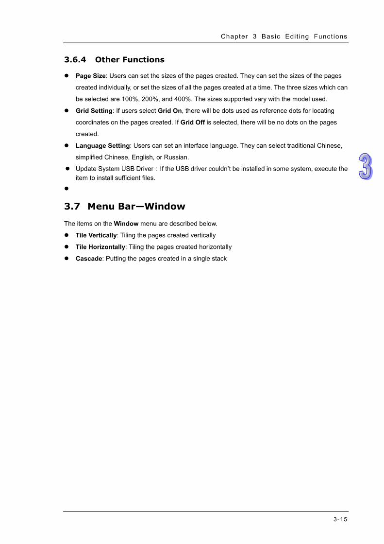
Users can set the time when a file is saved. If the users select the Enable checkbox and the Saving
at begging to compile option button in the AutoSave Setup window, the project created is saved
before it is compiled whenever Build All on the Compile menu, or on the standard toolbar is
clicked. If the users select the Enable checkbox, and set an interval in the AutoSave Setup window,
the project created will be automatically saved after the period of time set passes. After AutoSave
Setup on the Tool menu is clicked, the AutoSave Setup window will appear, as shown in Figure
3-17.
Figure 3-17 AutoSave Setup window
Chapter 3 Bas ic Edi t ing Funct ions
3-15
3.6.4 Other Functions
Page Size: Users can set the sizes of the pages created. They can set the sizes of the pages
created individually, or set the sizes of all the pages created at a time. The three sizes which can
be selected are 100%, 200%, and 400%. The sizes supported vary with the model used.
Grid Setting: If users select Grid On, there will be dots used as reference dots for locating
coordinates on the pages created. If Grid Off is selected, there will be no dots on the pages
created.
Language Setting: Users can set an interface language. They can select traditional Chinese,
simplified Chinese, English, or Russian.
Update System USB Driver:If the USB driver couldn’t be installed in some system, execute the item to install sufficient files.
3.7 Menu Bar—Window
The items on the Window menu are described below.
Tile Vertically: Tiling the pages created vertically
Tile Horizontally: Tiling the pages created horizontally
Cascade: Putting the pages created in a single stack
TPEditor User Manual
3-16
3.8 Menu Bar—Help
The items on the Help menu are described below.
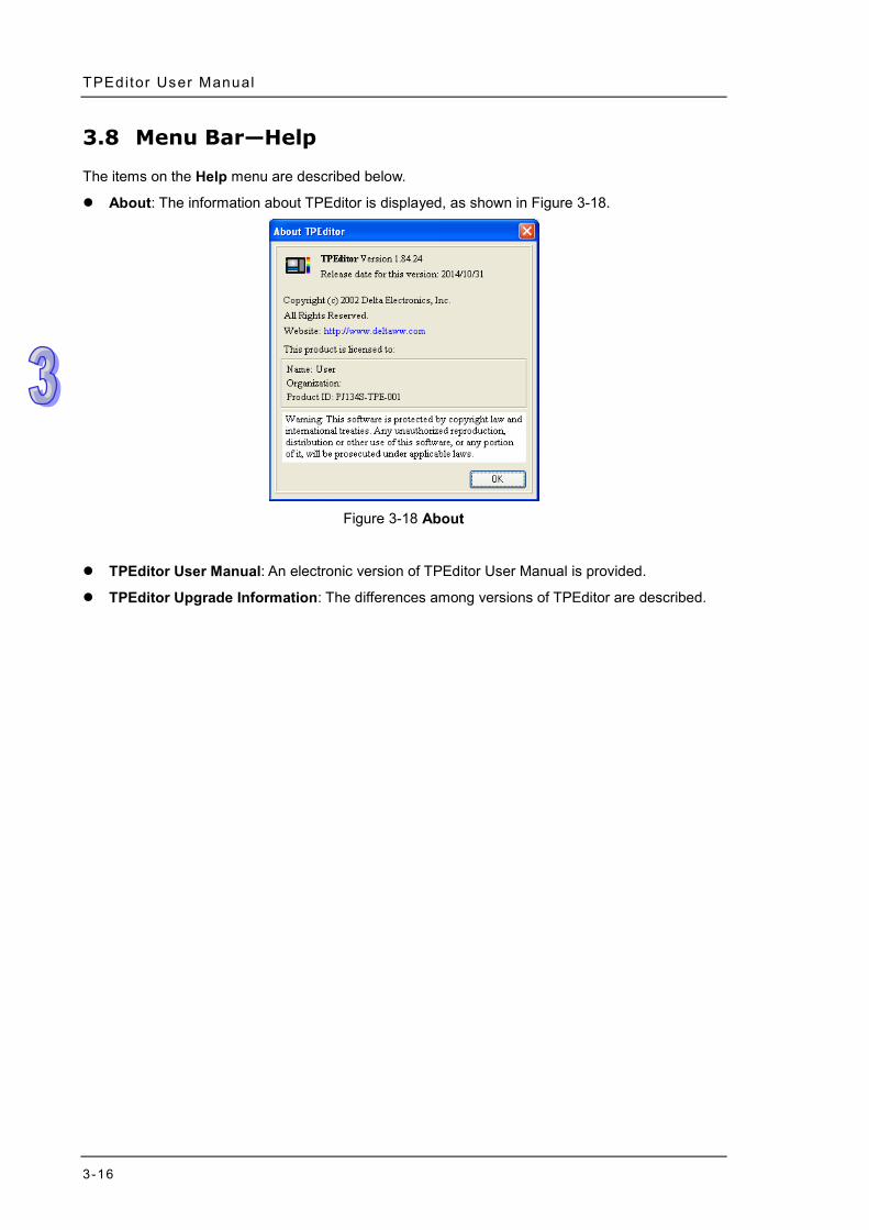
About: The information about TPEditor is displayed, as shown in Figure 3-18.
Figure 3-18 About
TPEditor User Manual: An electronic version of TPEditor User Manual is provided.
TPEditor Upgrade Information: The differences among versions of TPEditor are described.

Chapter 3 Bas ic Edi t ing Funct ions
3-17
MEMO
4-1
Chapter 4 Setting Objects Contents 4.1 Basic Setting Items .............................................................................. 4-2
4.1.1 Setting Related Devices ............................................................ 4-2 4.1.2 Setting Fonts ............................................................................... 4-3 4.1.3 Setting the Appearances of Objects ....................................... 4-4 4.1.4 Setting Numeric Objects ........................................................... 4-6 4.1.5 Setting Buttons ........................................................................... 4-6 4.1.6 Setting Locks .............................................................................. 4-8
4.2 Descriptions of Objects ........................................................................ 4-8 4.2.1 Geometric Graphic ..................................................................... 4-8 4.2.2 Static Text ................................................................................... 4-9 4.2.3 Numeric/ASCII Display ............................................................ 4-11 4.2.4 Bit Lamp ......................................................................................4-12 4.2.5 Word Lamp .................................................................................4-13 4.2.6 Static Bitmap .............................................................................4-14 4.2.7 Dynamic Bitmap ........................................................................4-15 4.2.8 Scale ............................................................................................4-17 4.2.9 Bar Graph ...................................................................................4-18 4.2.10 Circle Meter ................................................................................4-20 4.2.11 Message Display ........................................................................4-23 4.2.12 Button ..........................................................................................4-27 4.2.13 RTC Display ................................................................................4-47 4.2.14 Multi-State Bitmap/Label .........................................................4-48 4.2.15 Units ............................................................................................4-51 4.2.16 Numeric Input ............................................................................4-51 4.2.17 Curve ...........................................................................................4-54 4.2.18 X-Y Curve....................................................................................4-54 4.2.19 Delta Products Communication Device Setting ...................4-55 4.2.20 Active Alarm List ........................................................................4-57 4.2.21 Alarm History Table ...................................................................4-58 4.2.22 Alarm Moving Sigh ....................................................................4-59 4.2.23 Slider ...........................................................................................4-60 4.2.24 Input List ....................................................................................4-61 4.2.25 ComboBox ..................................................................................4-63
TPEditor User Manual
4-2
4.1 Basic Setting Items
The basic setting items which usually appear in an object setting window, a page setting window, or
a system setting window are described in this chapter. Users use TPEditor to set the multiple
functions of a text panel so that the pages that the users design and audio/video interaction can be
displayed.
4.1.1 Setting Related Devices
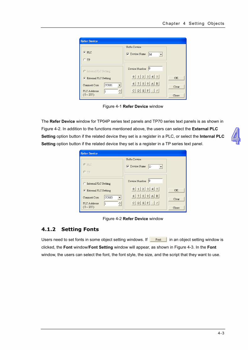
Related devices correspond to certain objects, pages, or functions of a system. If the value in a
related device is changed, the function to which the related device corresponds will be changed. For
example, the function of a lamp or the function of a buzzer will be changed if the value in the related
device corresponding to the function is changed. The values or states written into related devices
can be used as the input of operations in a program.
In object setting windows, page setting windows, and system setting windows, there are buttons
used to open the Refer Device window. Users can set a related device in the Refer Device window.
If the PLC option button is selected, the users can select a device name such as T, C, or M in the
Device Name drop-down list box. If the TP option button is selected, the users can select a device
name such as @V in the Device Name drop-down list box. The value in the Device Number box is
a decimal value. The users can select the device number they need by clicking numeric buttons. If a
related device is in an inverter, the Device Name checkbox must not be selected. If the Device
Name checkbox is not selected, $ will appear in the Device Name drop-down list box. $ represents
the absolute address of a parameter in an inverter. The users have to type an absolute address in
the Device Number box if the Device Name checkbox is not selected. For example, a related
device can be D10 or T1 in a PLC, or $2003 in an inverter.
The users can select the communication port connected to the equipment that the TP series text
panel used monitors in the Connect Com drop-down list box. For example, the users can select
COM1 (RS-232 port) or COM2 (RS-485/RS-422 port). After the users set a related device in the
Refer Device window, they have to click OK.
The Refer Device window for TP02G series text panels, TP04G series text panels, TP04G-AL-C
series text panels, TP04G-AL2 series text panels, TP04G-BL-C series text panels, TP04G-BL-CU
series text panels, TP05G series text panels, and TP08G series text panels is as shown in Figure
4-1.
Chapter 4 Set t ing Objects
4-3
Figure 4-1 Refer Device window
The Refer Device window for TP04P series text panels and TP70 series text panels is as shown in
Figure 4-2. In addition to the functions mentioned above, the users can select the External PLC
Setting option button if the related device they set is a register in a PLC, or select the Internal PLC
Setting option button if the related device they set is a register in a TP series text panel.
Figure 4-2 Refer Device window
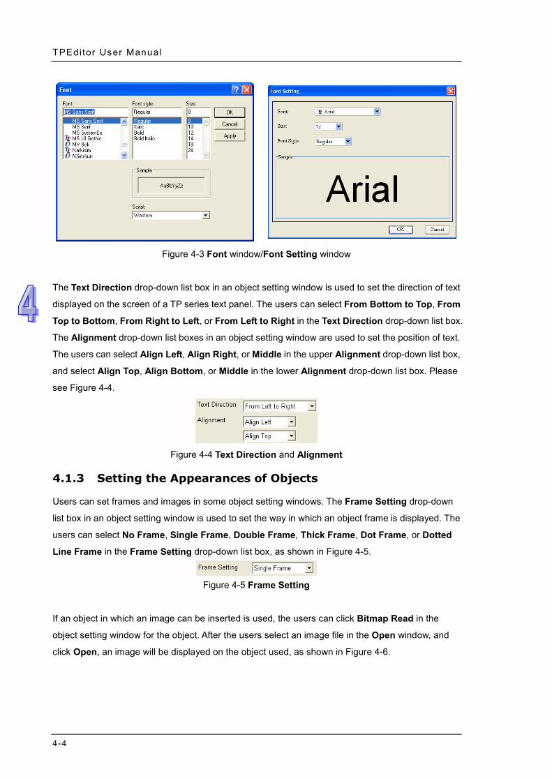
4.1.2 Setting Fonts
Users need to set fonts in some object setting windows. If in an object setting window is
clicked, the Font window/Font Setting window will appear, as shown in Figure 4-3. In the Font
window, the users can select the font, the font style, the size, and the script that they want to use.
TPEditor User Manual
4-4
Figure 4-3 Font window/Font Setting window
The Text Direction drop-down list box in an object setting window is used to set the direction of text
displayed on the screen of a TP series text panel. The users can select From Bottom to Top, From
Top to Bottom, From Right to Left, or From Left to Right in the Text Direction drop-down list box.
The Alignment drop-down list boxes in an object setting window are used to set the position of text.
The users can select Align Left, Align Right, or Middle in the upper Alignment drop-down list box,
and select Align Top, Align Bottom, or Middle in the lower Alignment drop-down list box. Please
see Figure 4-4.
Figure 4-4 Text Direction and Alignment
4.1.3 Setting the Appearances of Objects
Users can set frames and images in some object setting windows. The Frame Setting drop-down
list box in an object setting window is used to set the way in which an object frame is displayed. The
users can select No Frame, Single Frame, Double Frame, Thick Frame, Dot Frame, or Dotted
Line Frame in the Frame Setting drop-down list box, as shown in Figure 4-5.
Figure 4-5 Frame Setting
If an object in which an image can be inserted is used, the users can click Bitmap Read in the
object setting window for the object. After the users select an image file in the Open window, and
click Open, an image will be displayed on the object used, as shown in Figure 4-6.
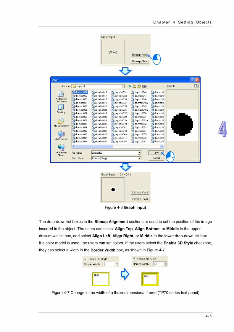
Chapter 4 Set t ing Objects
4-5
Figure 4-6 Graph Input
The drop-down list boxes in the Bitmap Alignment section are used to set the position of the image
inserted in the object. The users can select Align Top, Align Bottom, or Middle in the upper
drop-down list box, and select Align Left, Align Right, or Middle in the lower drop-down list box.
If a color model is used, the users can set colors. If the users select the Enable 3D Style checkbox,
they can select a width in the Border Width box, as shown in Figure 4-7.
Figure 4-7 Change in the width of a three-dimensional frame (TP70 series text panel)
TPEditor User Manual
4-6
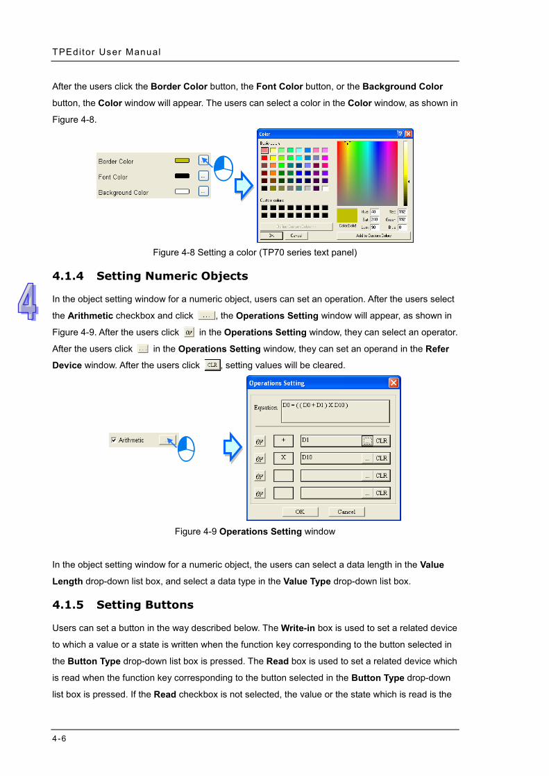
After the users click the Border Color button, the Font Color button, or the Background Color
button, the Color window will appear. The users can select a color in the Color window, as shown in
Figure 4-8.
Figure 4-8 Setting a color (TP70 series text panel)
4.1.4 Setting Numeric Objects
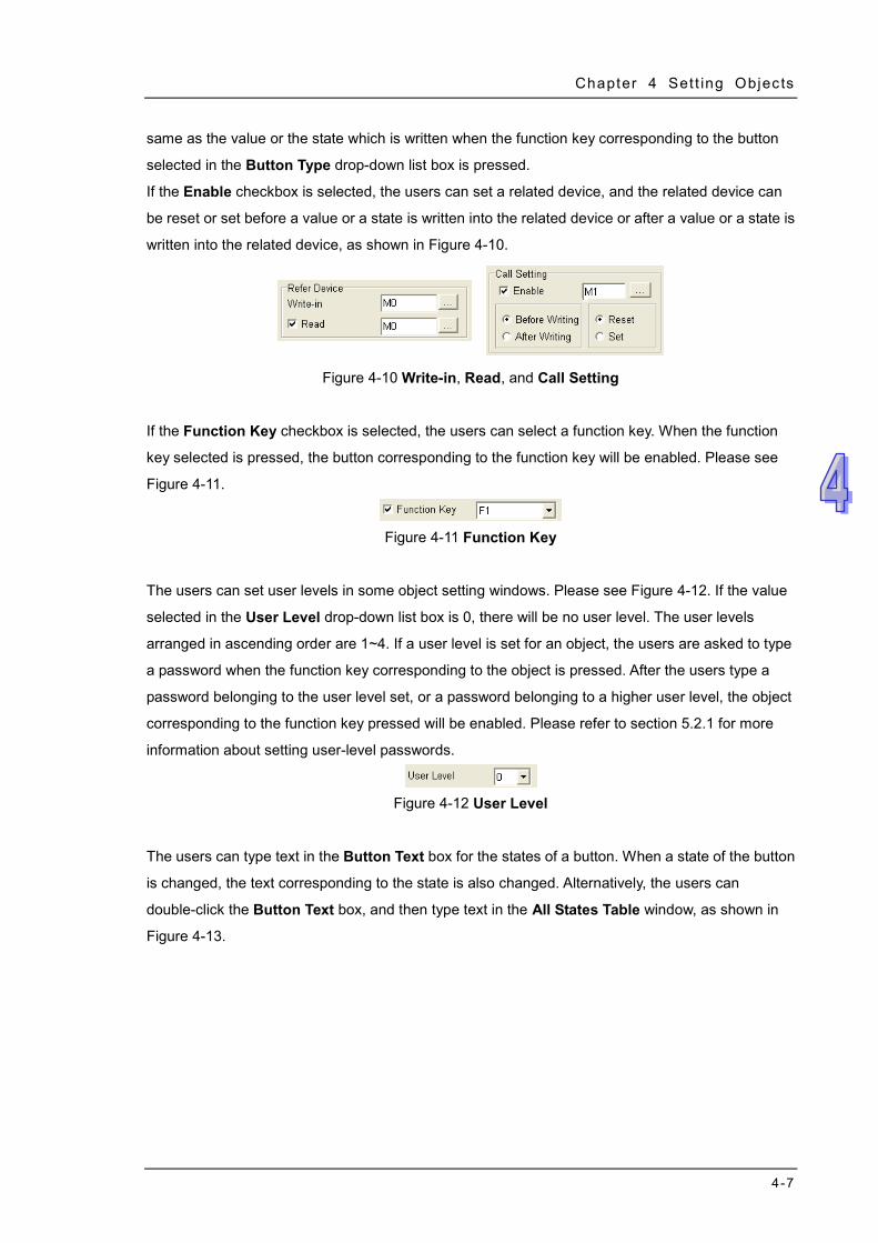
In the object setting window for a numeric object, users can set an operation. After the users select
the Arithmetic checkbox and click , the Operations Setting window will appear, as shown in
Figure 4-9. After the users click in the Operations Setting window, they can select an operator.
After the users click in the Operations Setting window, they can set an operand in the Refer
Device window. After the users click , setting values will be cleared.
Figure 4-9 Operations Setting window
In the object setting window for a numeric object, the users can select a data length in the Value
Length drop-down list box, and select a data type in the Value Type drop-down list box.
4.1.5 Setting Buttons
Users can set a button in the way described below. The Write-in box is used to set a related device
to which a value or a state is written when the function key corresponding to the button selected in
the Button Type drop-down list box is pressed. The Read box is used to set a related device which
is read when the function key corresponding to the button selected in the Button Type drop-down
list box is pressed. If the Read checkbox is not selected, the value or the state which is read is the
Chapter 4 Set t ing Objects
4-7
same as the value or the state which is written when the function key corresponding to the button
selected in the Button Type drop-down list box is pressed.
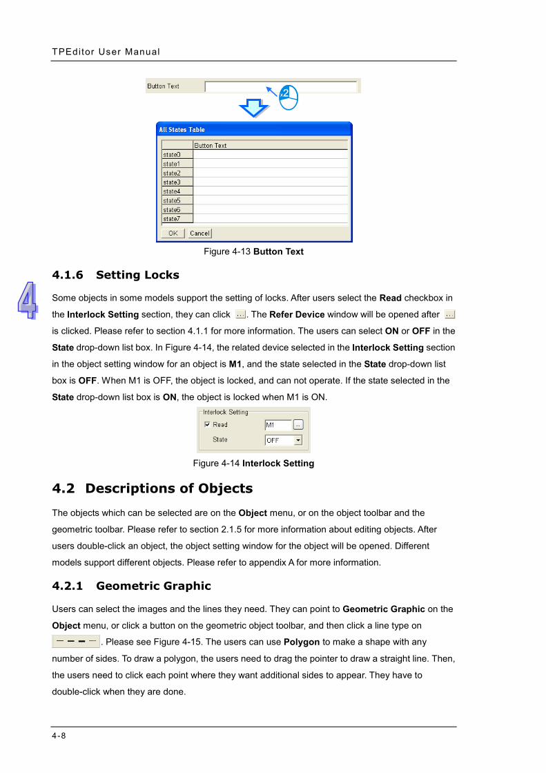
If the Enable checkbox is selected, the users can set a related device, and the related device can
be reset or set before a value or a state is written into the related device or after a value or a state is
written into the related device, as shown in Figure 4-10.
Figure 4-10 Write-in, Read, and Call Setting
If the Function Key checkbox is selected, the users can select a function key. When the function
key selected is pressed, the button corresponding to the function key will be enabled. Please see
Figure 4-11.
Figure 4-11 Function Key
The users can set user levels in some object setting windows. Please see Figure 4-12. If the value
selected in the User Level drop-down list box is 0, there will be no user level. The user levels
arranged in ascending order are 1~4. If a user level is set for an object, the users are asked to type
a password when the function key corresponding to the object is pressed. After the users type a
password belonging to the user level set, or a password belonging to a higher user level, the object
corresponding to the function key pressed will be enabled. Please refer to section 5.2.1 for more
information about setting user-level passwords.
Figure 4-12 User Level
The users can type text in the Button Text box for the states of a button. When a state of the button
is changed, the text corresponding to the state is also changed. Alternatively, the users can
double-click the Button Text box, and then type text in the All States Table window, as shown in
Figure 4-13.
TPEditor User Manual
4-8
Figure 4-13 Button Text
4.1.6 Setting Locks
Some objects in some models support the setting of locks. After users select the Read checkbox in
the Interlock Setting section, they can click . The Refer Device window will be opened after
is clicked. Please refer to section 4.1.1 for more information. The users can select ON or OFF in the
State drop-down list box. In Figure 4-14, the related device selected in the Interlock Setting section
in the object setting window for an object is M1, and the state selected in the State drop-down list
box is OFF. When M1 is OFF, the object is locked, and can not operate. If the state selected in the
State drop-down list box is ON, the object is locked when M1 is ON.
Figure 4-14 Interlock Setting
4.2 Descriptions of Objects
The objects which can be selected are on the Object menu, or on the object toolbar and the
geometric toolbar. Please refer to section 2.1.5 for more information about editing objects. After
users double-click an object, the object setting window for the object will be opened. Different
models support different objects. Please refer to appendix A for more information.
4.2.1 Geometric Graphic
Users can select the images and the lines they need. They can point to Geometric Graphic on the
Object menu, or click a button on the geometric object toolbar, and then click a line type on
. Please see Figure 4-15. The users can use Polygon to make a shape with any
number of sides. To draw a polygon, the users need to drag the pointer to draw a straight line. Then,
the users need to click each point where they want additional sides to appear. They have to
double-click when they are done.
Chapter 4 Set t ing Objects
4-9
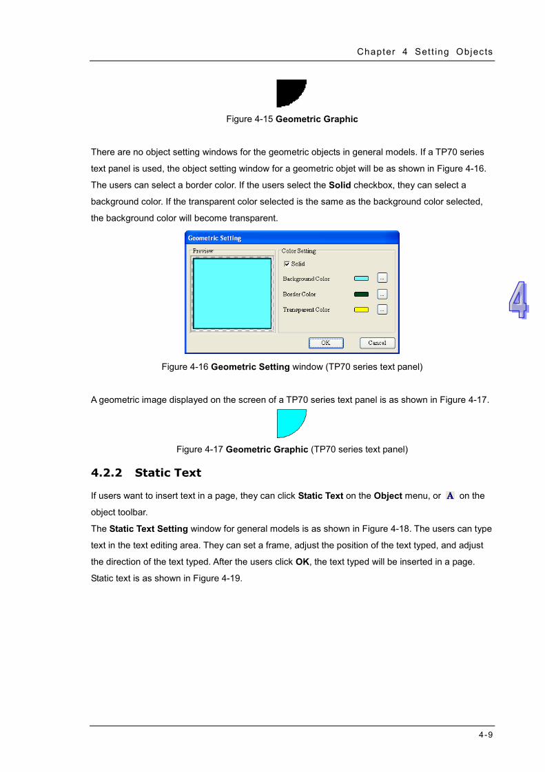
Figure 4-15 Geometric Graphic
There are no object setting windows for the geometric objects in general models. If a TP70 series
text panel is used, the object setting window for a geometric objet will be as shown in Figure 4-16.
The users can select a border color. If the users select the Solid checkbox, they can select a
background color. If the transparent color selected is the same as the background color selected,
the background color will become transparent.
Figure 4-16 Geometric Setting window (TP70 series text panel)
A geometric image displayed on the screen of a TP70 series text panel is as shown in Figure 4-17.
Figure 4-17 Geometric Graphic (TP70 series text panel)
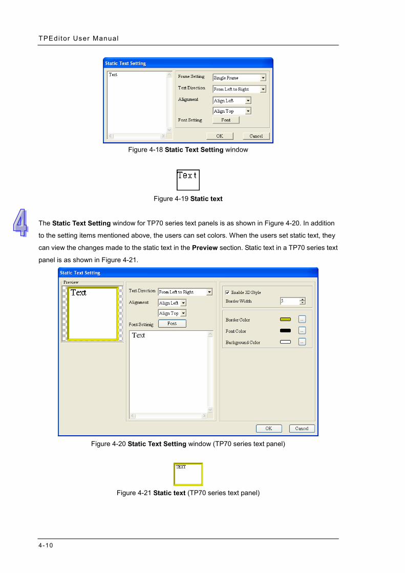
4.2.2 Static Text
If users want to insert text in a page, they can click Static Text on the Object menu, or on the
object toolbar.
The Static Text Setting window for general models is as shown in Figure 4-18. The users can type
text in the text editing area. They can set a frame, adjust the position of the text typed, and adjust
the direction of the text typed. After the users click OK, the text typed will be inserted in a page.
Static text is as shown in Figure 4-19.
TPEditor User Manual
4-10
Figure 4-18 Static Text Setting window
Figure 4-19 Static text
The Static Text Setting window for TP70 series text panels is as shown in Figure 4-20. In addition
to the setting items mentioned above, the users can set colors. When the users set static text, they
can view the changes made to the static text in the Preview section. Static text in a TP70 series text
panel is as shown in Figure 4-21.
Figure 4-20 Static Text Setting window (TP70 series text panel)
Figure 4-21 Static text (TP70 series text panel)
Chapter 4 Set t ing Objects
4-11
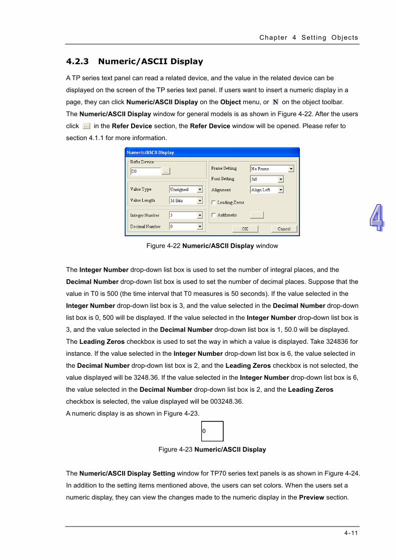
4.2.3 Numeric/ASCII Display
A TP series text panel can read a related device, and the value in the related device can be
displayed on the screen of the TP series text panel. If users want to insert a numeric display in a
page, they can click Numeric/ASCII Display on the Object menu, or on the object toolbar.
The Numeric/ASCII Display window for general models is as shown in Figure 4-22. After the users
click in the Refer Device section, the Refer Device window will be opened. Please refer to
section 4.1.1 for more information.
Figure 4-22 Numeric/ASCII Display window
The Integer Number drop-down list box is used to set the number of integral places, and the
Decimal Number drop-down list box is used to set the number of decimal places. Suppose that the
value in T0 is 500 (the time interval that T0 measures is 50 seconds). If the value selected in the
Integer Number drop-down list box is 3, and the value selected in the Decimal Number drop-down
list box is 0, 500 will be displayed. If the value selected in the Integer Number drop-down list box is
3, and the value selected in the Decimal Number drop-down list box is 1, 50.0 will be displayed.
The Leading Zeros checkbox is used to set the way in which a value is displayed. Take 324836 for
instance. If the value selected in the Integer Number drop-down list box is 6, the value selected in
the Decimal Number drop-down list box is 2, and the Leading Zeros checkbox is not selected, the
value displayed will be 3248.36. If the value selected in the Integer Number drop-down list box is 6,
the value selected in the Decimal Number drop-down list box is 2, and the Leading Zeros
checkbox is selected, the value displayed will be 003248.36.
A numeric display is as shown in Figure 4-23.
Figure 4-23 Numeric/ASCII Display
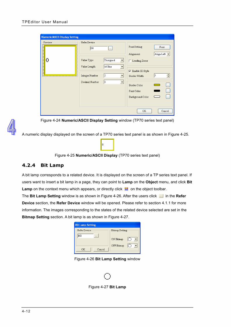
The Numeric/ASCII Display Setting window for TP70 series text panels is as shown in Figure 4-24.
In addition to the setting items mentioned above, the users can set colors. When the users set a
numeric display, they can view the changes made to the numeric display in the Preview section.
TPEditor User Manual
4-12
Figure 4-24 Numeric/ASCII Display Setting window (TP70 series text panel)
A numeric display displayed on the screen of a TP70 series text panel is as shown in Figure 4-25.
Figure 4-25 Numeric/ASCII Display (TP70 series text panel)
4.2.4 Bit Lamp
A bit lamp corresponds to a related device. It is displayed on the screen of a TP series text panel. If
users want to insert a bit lamp in a page, they can point to Lamp on the Object menu, and click Bit
Lamp on the context menu which appears, or directly click on the object toolbar.
The Bit Lamp Setting window is as shown in Figure 4-26. After the users click in the Refer
Device section, the Refer Device window will be opened. Please refer to section 4.1.1 for more
information. The images corresponding to the states of the related device selected are set in the
Bitmap Setting section. A bit lamp is as shown in Figure 4-27.
Figure 4-26 Bit Lamp Setting window
Figure 4-27 Bit Lamp
Chapter 4 Set t ing Objects
4-13
4.2.5 Word Lamp
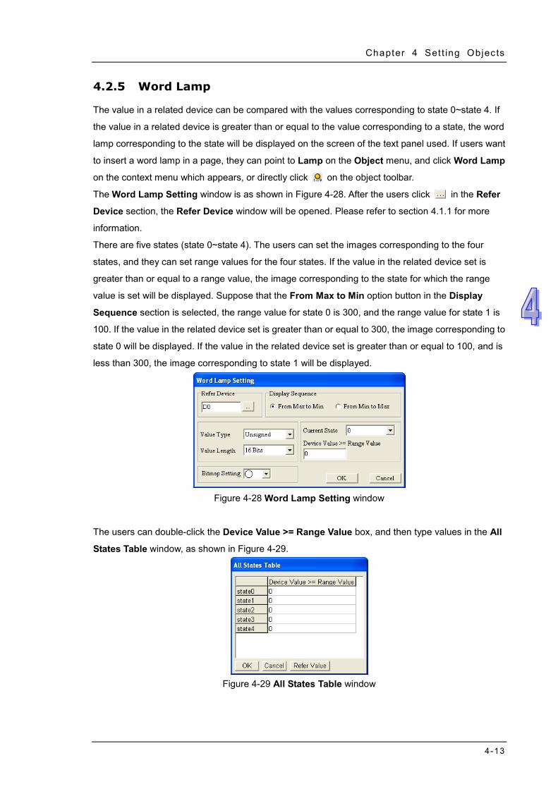
The value in a related device can be compared with the values corresponding to state 0~state 4. If
the value in a related device is greater than or equal to the value corresponding to a state, the word
lamp corresponding to the state will be displayed on the screen of the text panel used. If users want
to insert a word lamp in a page, they can point to Lamp on the Object menu, and click Word Lamp
on the context menu which appears, or directly click on the object toolbar.
The Word Lamp Setting window is as shown in Figure 4-28. After the users click in the Refer
Device section, the Refer Device window will be opened. Please refer to section 4.1.1 for more
information.
There are five states (state 0~state 4). The users can set the images corresponding to the four
states, and they can set range values for the four states. If the value in the related device set is
greater than or equal to a range value, the image corresponding to the state for which the range
value is set will be displayed. Suppose that the From Max to Min option button in the Display
Sequence section is selected, the range value for state 0 is 300, and the range value for state 1 is
100. If the value in the related device set is greater than or equal to 300, the image corresponding to
state 0 will be displayed. If the value in the related device set is greater than or equal to 100, and is
less than 300, the image corresponding to state 1 will be displayed.
Figure 4-28 Word Lamp Setting window
The users can double-click the Device Value >= Range Value box, and then type values in the All
States Table window, as shown in Figure 4-29.
Figure 4-29 All States Table window
TPEditor User Manual
4-14
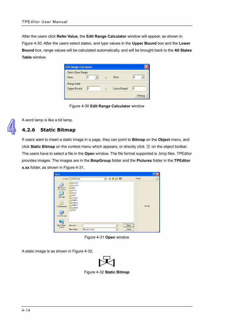
After the users click Refer Value, the Edit Range Calculator window will appear, as shown in
Figure 4-30. After the users select states, and type values in the Upper Bound box and the Lower
Bound box, range values will be calculated automatically, and will be brought back to the All States
Table window.
Figure 4-30 Edit Range Calculator window
A word lamp is like a bit lamp.
4.2.6 Static Bitmap
If users want to insert a static image in a page, they can point to Bitmap on the Object menu, and
click Static Bitmap on the context menu which appears, or directly click on the object toolbar.
The users have to select a file in the Open window. The file format supported is .bmp files. TPEditor
provides images. The images are in the BmpGroup folder and the Pictures folder in the TPEditor
x.xx folder, as shown in Figure 4-31.
Figure 4-31 Open window
A static image is as shown in Figure 4-32.
Figure 4-32 Static Bitmap
Chapter 4 Set t ing Objects
4-15
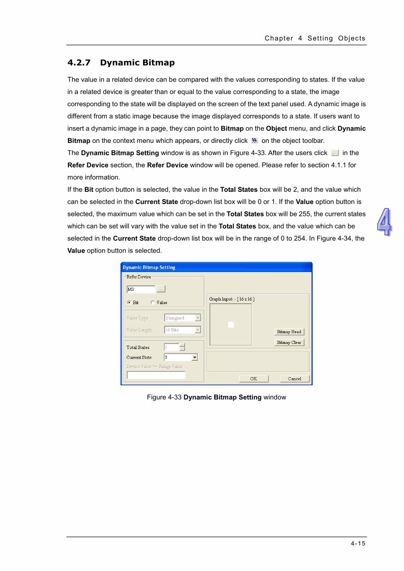
4.2.7 Dynamic Bitmap
The value in a related device can be compared with the values corresponding to states. If the value
in a related device is greater than or equal to the value corresponding to a state, the image
corresponding to the state will be displayed on the screen of the text panel used. A dynamic image is
different from a static image because the image displayed corresponds to a state. If users want to
insert a dynamic image in a page, they can point to Bitmap on the Object menu, and click Dynamic
Bitmap on the context menu which appears, or directly click on the object toolbar.
The Dynamic Bitmap Setting window is as shown in Figure 4-33. After the users click in the
Refer Device section, the Refer Device window will be opened. Please refer to section 4.1.1 for
more information.
If the Bit option button is selected, the value in the Total States box will be 2, and the value which
can be selected in the Current State drop-down list box will be 0 or 1. If the Value option button is
selected, the maximum value which can be set in the Total States box will be 255, the current states
which can be set will vary with the value set in the Total States box, and the value which can be
selected in the Current State drop-down list box will be in the range of 0 to 254. In Figure 4-34, the
Value option button is selected.
Figure 4-33 Dynamic Bitmap Setting window
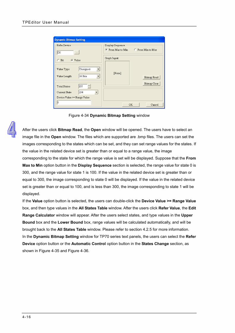
TPEditor User Manual
4-16
Figure 4-34 Dynamic Bitmap Setting window
After the users click Bitmap Read, the Open window will be opened. The users have to select an
image file in the Open window. The files which are supported are .bmp files. The users can set the
images corresponding to the states which can be set, and they can set range values for the states. If
the value in the related device set is greater than or equal to a range value, the image
corresponding to the state for which the range value is set will be displayed. Suppose that the From
Max to Min option button in the Display Sequence section is selected, the range value for state 0 is
300, and the range value for state 1 is 100. If the value in the related device set is greater than or
equal to 300, the image corresponding to state 0 will be displayed. If the value in the related device
set is greater than or equal to 100, and is less than 300, the image corresponding to state 1 will be
displayed.
If the Value option button is selected, the users can double-click the Device Value >= Range Value
box, and then type values in the All States Table window. After the users click Refer Value, the Edit
Range Calculator window will appear. After the users select states, and type values in the Upper
Bound box and the Lower Bound box, range values will be calculated automatically, and will be
brought back to the All States Table window. Please refer to section 4.2.5 for more information.
In the Dynamic Bitmap Setting window for TP70 series text panels, the users can select the Refer
Device option button or the Automatic Control option button in the States Change section, as
shown in Figure 4-35 and Figure 4-36.
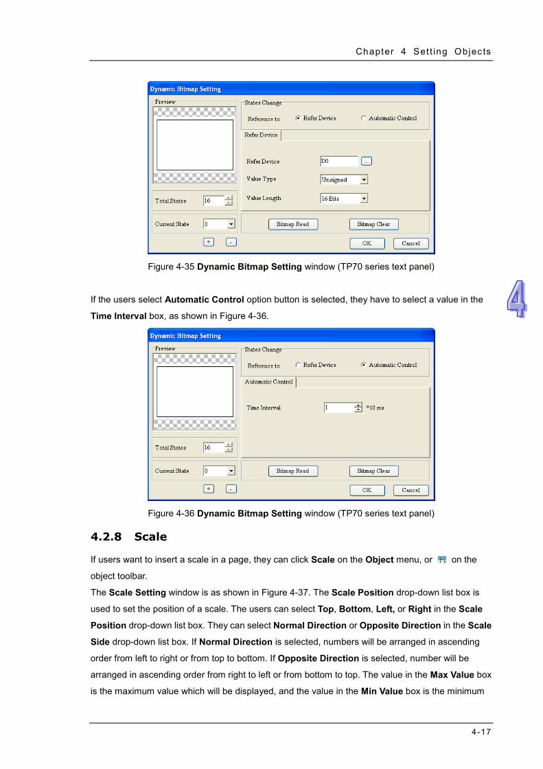
Chapter 4 Set t ing Objects
4-17
Figure 4-35 Dynamic Bitmap Setting window (TP70 series text panel)
If the users select Automatic Control option button is selected, they have to select a value in the
Time Interval box, as shown in Figure 4-36.
Figure 4-36 Dynamic Bitmap Setting window (TP70 series text panel)
4.2.8 Scale
If users want to insert a scale in a page, they can click Scale on the Object menu, or on the
object toolbar.
The Scale Setting window is as shown in Figure 4-37. The Scale Position drop-down list box is
used to set the position of a scale. The users can select Top, Bottom, Left, or Right in the Scale
Position drop-down list box. They can select Normal Direction or Opposite Direction in the Scale
Side drop-down list box. If Normal Direction is selected, numbers will be arranged in ascending
order from left to right or from top to bottom. If Opposite Direction is selected, number will be
arranged in ascending order from right to left or from bottom to top. The value in the Max Value box
is the maximum value which will be displayed, and the value in the Min Value box is the minimum
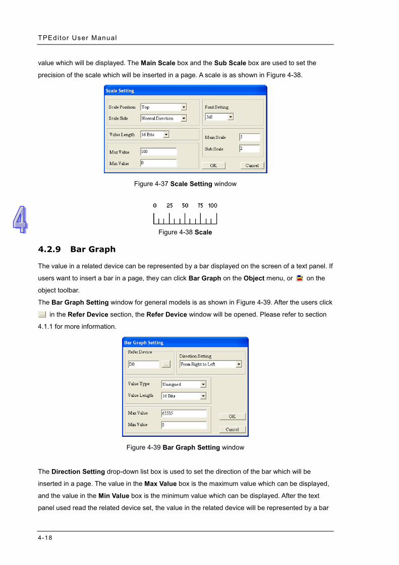
TPEditor User Manual
4-18
value which will be displayed. The Main Scale box and the Sub Scale box are used to set the
precision of the scale which will be inserted in a page. A scale is as shown in Figure 4-38.
Figure 4-37 Scale Setting window
Figure 4-38 Scale
4.2.9 Bar Graph
The value in a related device can be represented by a bar displayed on the screen of a text panel. If
users want to insert a bar in a page, they can click Bar Graph on the Object menu, or on the
object toolbar.
The Bar Graph Setting window for general models is as shown in Figure 4-39. After the users click
in the Refer Device section, the Refer Device window will be opened. Please refer to section
4.1.1 for more information.
Figure 4-39 Bar Graph Setting window
The Direction Setting drop-down list box is used to set the direction of the bar which will be
inserted in a page. The value in the Max Value box is the maximum value which can be displayed,
and the value in the Min Value box is the minimum value which can be displayed. After the text
panel used read the related device set, the value in the related device will be represented by a bar
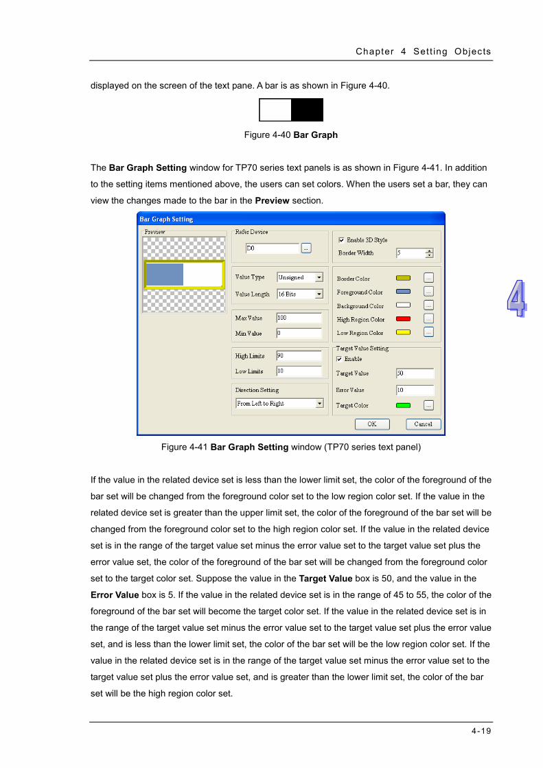
Chapter 4 Set t ing Objects
4-19
displayed on the screen of the text pane. A bar is as shown in Figure 4-40.
Figure 4-40 Bar Graph
The Bar Graph Setting window for TP70 series text panels is as shown in Figure 4-41. In addition
to the setting items mentioned above, the users can set colors. When the users set a bar, they can
view the changes made to the bar in the Preview section.
Figure 4-41 Bar Graph Setting window (TP70 series text panel)
If the value in the related device set is less than the lower limit set, the color of the foreground of the
bar set will be changed from the foreground color set to the low region color set. If the value in the
related device set is greater than the upper limit set, the color of the foreground of the bar set will be
changed from the foreground color set to the high region color set. If the value in the related device
set is in the range of the target value set minus the error value set to the target value set plus the
error value set, the color of the foreground of the bar set will be changed from the foreground color
set to the target color set. Suppose the value in the Target Value box is 50, and the value in the
Error Value box is 5. If the value in the related device set is in the range of 45 to 55, the color of the
foreground of the bar set will become the target color set. If the value in the related device set is in
the range of the target value set minus the error value set to the target value set plus the error value
set, and is less than the lower limit set, the color of the bar set will be the low region color set. If the
value in the related device set is in the range of the target value set minus the error value set to the
target value set plus the error value set, and is greater than the lower limit set, the color of the bar
set will be the high region color set.
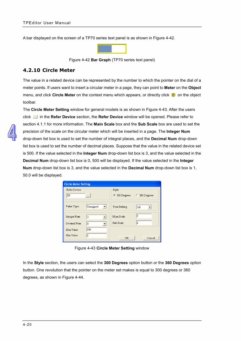
TPEditor User Manual
4-20
A bar displayed on the screen of a TP70 series text panel is as shown in Figure 4-42.
Figure 4-42 Bar Graph (TP70 series text panel)
4.2.10 Circle Meter
The value in a related device can be represented by the number to which the pointer on the dial of a
meter points. If users want to insert a circular meter in a page, they can point to Meter on the Object
menu, and click Circle Meter on the context menu which appears, or directly click on the object
toolbar.
The Circle Meter Setting window for general models is as shown in Figure 4-43. After the users
click in the Refer Device section, the Refer Device window will be opened. Please refer to
section 4.1.1 for more information. The Main Scale box and the Sub Scale box are used to set the
precision of the scale on the circular meter which will be inserted in a page. The Integer Num
drop-down list box is used to set the number of integral places, and the Decimal Num drop-down
list box is used to set the number of decimal places. Suppose that the value in the related device set
is 500. If the value selected in the Integer Num drop-down list box is 3, and the value selected in the
Decimal Num drop-down list box is 0, 500 will be displayed. If the value selected in the Integer
Num drop-down list box is 3, and the value selected in the Decimal Num drop-down list box is 1,
50.0 will be displayed.
Figure 4-43 Circle Meter Setting window
In the Style section, the users can select the 300 Degrees option button or the 360 Degrees option
button. One revolution that the pointer on the meter set makes is equal to 300 degrees or 360
degrees, as shown in Figure 4-44.
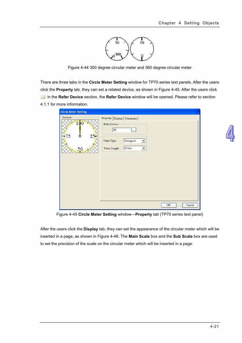
Chapter 4 Set t ing Objects
4-21
Figure 4-44 300 degree circular meter and 360 degree circular meter
There are three tabs in the Circle Meter Setting window for TP70 series text panels. After the users
click the Property tab, they can set a related device, as shown in Figure 4-45. After the users click
in the Refer Device section, the Refer Device window will be opened. Please refer to section
4.1.1 for more information.
Figure 4-45 Circle Meter Setting window—Property tab (TP70 series text panel)
After the users click the Display tab, they can set the appearance of the circular meter which will be
inserted in a page, as shown in Figure 4-46. The Main Scale box and the Sub Scale box are used
to set the precision of the scale on the circular meter which will be inserted in a page.
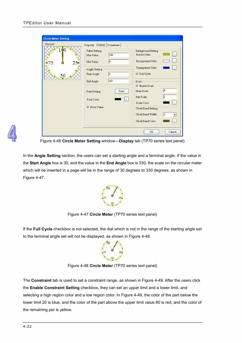
TPEditor User Manual
4-22
Figure 4-46 Circle Meter Setting window—Display tab (TP70 series text panel)
In the Angle Setting section, the users can set a starting angle and a terminal angle. If the value in
the Start Angle box is 30, and the value in the End Angle box is 330, the scale on the circular meter
which will be inserted in a page will be in the range of 30 degrees to 330 degrees, as shown in
Figure 4-47.
Figure 4-47 Circle Meter (TP70 series text panel)
If the Full Cycle checkbox is not selected, the dial which is not in the range of the starting angle set
to the terminal angle set will not be displayed, as shown in Figure 4-48.
Figure 4-48 Circle Meter (TP70 series text panel)
The Constraint tab is used to set a constraint range, as shown in Figure 4-49. After the users click
the Enable Constraint Setting checkbox, they can set an upper limit and a lower limit, and
selecting a high region color and a low region color. In Figure 4-49, the color of the part below the
lower limit 20 is blue, and the color of the part above the upper limit value 80 is red, and the color of
the remaining par is yellow.
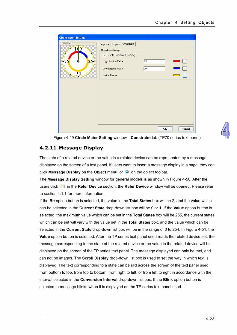
Chapter 4 Set t ing Objects
4-23
Figure 4-49 Circle Meter Setting window—Constraint tab (TP70 series text panel)
4.2.11 Message Display
The state of a related device or the value in a related device can be represented by a message
displayed on the screen of a text panel. If users want to insert a message display in a page, they can
click Message Display on the Object menu, or on the object toolbar.
The Message Display Setting window for general models is as shown in Figure 4-50. After the
users click in the Refer Device section, the Refer Device window will be opened. Please refer
to section 4.1.1 for more information.
If the Bit option button is selected, the value in the Total States box will be 2, and the value which
can be selected in the Current State drop-down list box will be 0 or 1. If the Value option button is
selected, the maximum value which can be set in the Total States box will be 255, the current states
which can be set will vary with the value set in the Total States box, and the value which can be
selected in the Current State drop-down list box will be in the range of 0 to 254. In Figure 4-51, the
Value option button is selected. After the TP series text panel used reads the related device set, the
message corresponding to the state of the related device or the value in the related device will be
displayed on the screen of the TP series text panel. The message displayed can only be text, and
can not be images. The Scroll Display drop-down list box is used to set the way in which text is
displayed. The text corresponding to a state can be slid across the screen of the text panel used
from bottom to top, from top to bottom, from right to left, or from left to right in accordance with the
interval selected in the Conversion Interval drop-down list box. If the Blink option button is
selected, a message blinks when it is displayed on the TP series text panel used.
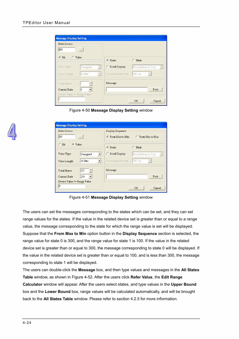
TPEditor User Manual
4-24
Figure 4-50 Message Display Setting window
Figure 4-51 Message Display Setting window
The users can set the messages corresponding to the states which can be set, and they can set
range values for the states. If the value in the related device set is greater than or equal to a range
value, the message corresponding to the state for which the range value is set will be displayed.
Suppose that the From Max to Min option button in the Display Sequence section is selected, the
range value for state 0 is 300, and the range value for state 1 is 100. If the value in the related
device set is greater than or equal to 300, the message corresponding to state 0 will be displayed. If
the value in the related device set is greater than or equal to 100, and is less than 300, the message
corresponding to state 1 will be displayed.
The users can double-click the Message box, and then type values and messages in the All States
Table window, as shown in Figure 4-52. After the users click Refer Value, the Edit Range
Calculator window will appear. After the users select states, and type values in the Upper Bound
box and the Lower Bound box, range values will be calculated automatically, and will be brought
back to the All States Table window. Please refer to section 4.2.5 for more information.
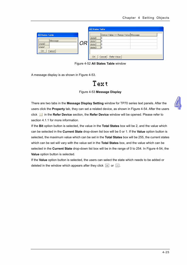
Chapter 4 Set t ing Objects
4-25
Figure 4-52 All States Table window
A message display is as shown in Figure 4-53.
Figure 4-53 Message Display
There are two tabs in the Message Display Setting window for TP70 series text panels. After the
users click the Property tab, they can set a related device, as shown in Figure 4-54. After the users
click in the Refer Device section, the Refer Device window will be opened. Please refer to
section 4.1.1 for more information.
If the Bit option button is selected, the value in the Total States box will be 2, and the value which
can be selected in the Current State drop-down list box will be 0 or 1. If the Value option button is
selected, the maximum value which can be set in the Total States box will be 255, the current states
which can be set will vary with the value set in the Total States box, and the value which can be
selected in the Current State drop-down list box will be in the range of 0 to 254. In Figure 4-54, the
Value option button is selected.
If the Value option button is selected, the users can select the state which needs to be added or
deleted in the window which appears after they click or .
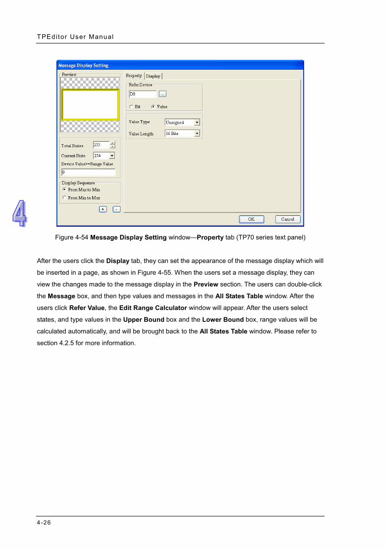
TPEditor User Manual
4-26
Figure 4-54 Message Display Setting window—Property tab (TP70 series text panel)
After the users click the Display tab, they can set the appearance of the message display which will
be inserted in a page, as shown in Figure 4-55. When the users set a message display, they can
view the changes made to the message display in the Preview section. The users can double-click
the Message box, and then type values and messages in the All States Table window. After the
users click Refer Value, the Edit Range Calculator window will appear. After the users select
states, and type values in the Upper Bound box and the Lower Bound box, range values will be
calculated automatically, and will be brought back to the All States Table window. Please refer to
section 4.2.5 for more information.
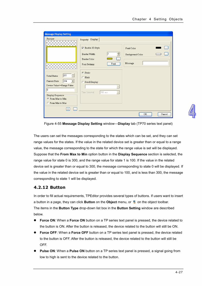
Chapter 4 Set t ing Objects
4-27
Figure 4-55 Message Display Setting window—Display tab (TP70 series text panel)
The users can set the messages corresponding to the states which can be set, and they can set
range values for the states. If the value in the related device set is greater than or equal to a range
value, the message corresponding to the state for which the range value is set will be displayed.
Suppose that the From Max to Min option button in the Display Sequence section is selected, the
range value for state 0 is 300, and the range value for state 1 is 100. If the value in the related
device set is greater than or equal to 300, the message corresponding to state 0 will be displayed. If
the value in the related device set is greater than or equal to 100, and is less than 300, the message
corresponding to state 1 will be displayed.
4.2.12 Button
In order to fill actual requirements, TPEditor provides several types of buttons. If users want to insert
a button in a page, they can click Button on the Object menu, or on the object toolbar.
The items in the Button Type drop-down list box in the Button Setting window are described
below.
Force ON: When a Force ON button on a TP series text panel is pressed, the device related to
the button is ON. After the button is released, the device related to the button will still be ON.
Force OFF: When a Force OFF button on a TP series text panel is pressed, the device related
to the button is OFF. After the button is released, the device related to the button will still be
OFF.
Pulse ON: When a Pulse ON button on a TP series text panel is pressed, a signal going from
low to high is sent to the device related to the button.
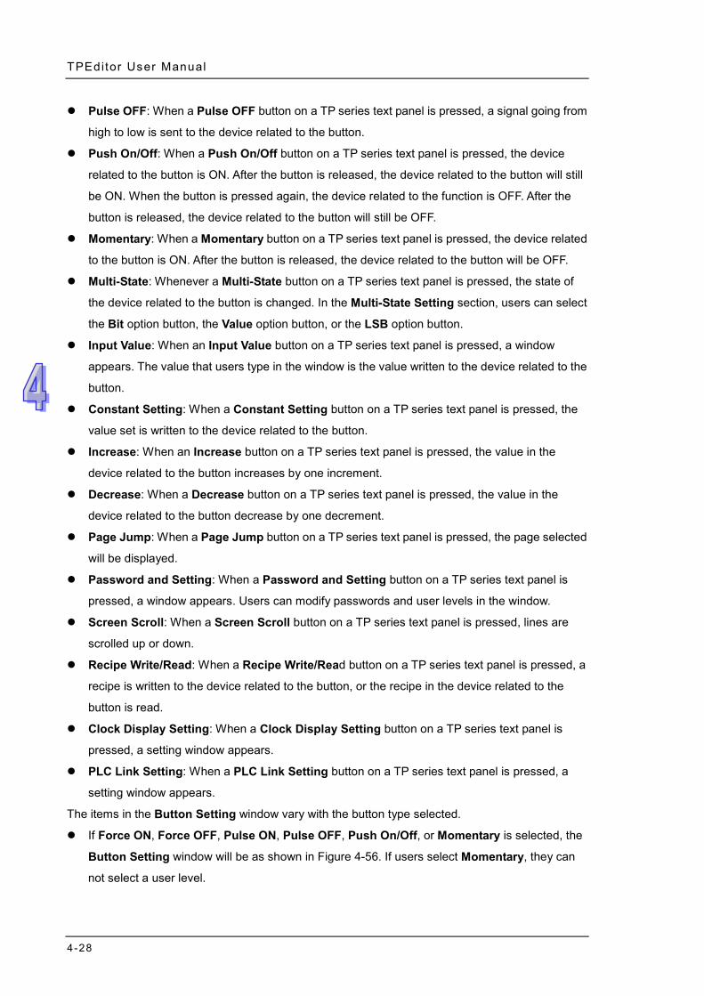
TPEditor User Manual
4-28
Pulse OFF: When a Pulse OFF button on a TP series text panel is pressed, a signal going from
high to low is sent to the device related to the button.
Push On/Off: When a Push On/Off button on a TP series text panel is pressed, the device
related to the button is ON. After the button is released, the device related to the button will still
be ON. When the button is pressed again, the device related to the function is OFF. After the
button is released, the device related to the button will still be OFF.
Momentary: When a Momentary button on a TP series text panel is pressed, the device related
to the button is ON. After the button is released, the device related to the button will be OFF.
Multi-State: Whenever a Multi-State button on a TP series text panel is pressed, the state of
the device related to the button is changed. In the Multi-State Setting section, users can select
the Bit option button, the Value option button, or the LSB option button.
Input Value: When an Input Value button on a TP series text panel is pressed, a window
appears. The value that users type in the window is the value written to the device related to the
button.
Constant Setting: When a Constant Setting button on a TP series text panel is pressed, the
value set is written to the device related to the button.
Increase: When an Increase button on a TP series text panel is pressed, the value in the
device related to the button increases by one increment.
Decrease: When a Decrease button on a TP series text panel is pressed, the value in the
device related to the button decrease by one decrement.
Page Jump: When a Page Jump button on a TP series text panel is pressed, the page selected
will be displayed.
Password and Setting: When a Password and Setting button on a TP series text panel is
pressed, a window appears. Users can modify passwords and user levels in the window.
Screen Scroll: When a Screen Scroll button on a TP series text panel is pressed, lines are
scrolled up or down.
Recipe Write/Read: When a Recipe Write/Read button on a TP series text panel is pressed, a
recipe is written to the device related to the button, or the recipe in the device related to the
button is read.
Clock Display Setting: When a Clock Display Setting button on a TP series text panel is
pressed, a setting window appears.
PLC Link Setting: When a PLC Link Setting button on a TP series text panel is pressed, a
setting window appears.
The items in the Button Setting window vary with the button type selected.
If Force ON, Force OFF, Pulse ON, Pulse OFF, Push On/Off, or Momentary is selected, the
Button Setting window will be as shown in Figure 4-56. If users select Momentary, they can
not select a user level.
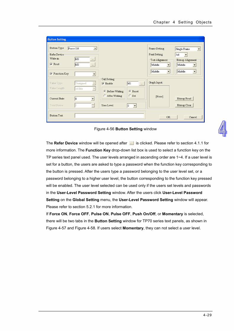
Chapter 4 Set t ing Objects
4-29
Figure 4-56 Button Setting window
The Refer Device window will be opened after is clicked. Please refer to section 4.1.1 for
more information. The Function Key drop-down list box is used to select a function key on the
TP series text panel used. The user levels arranged in ascending order are 1~4. If a user level is
set for a button, the users are asked to type a password when the function key corresponding to
the button is pressed. After the users type a password belonging to the user level set, or a
password belonging to a higher user level, the button corresponding to the function key pressed
will be enabled. The user level selected can be used only if the users set levels and passwords
in the User-Level Password Setting window. After the users click User-Level Password
Setting on the Global Setting menu, the User-Level Password Setting window will appear.
Please refer to section 5.2.1 for more information.
If Force ON, Force OFF, Pulse ON, Pulse OFF, Push On/Off, or Momentary is selected,
there will be two tabs in the Button Setting window for TP70 series text panels, as shown in
Figure 4-57 and Figure 4-58. If users select Momentary, they can not select a user level.
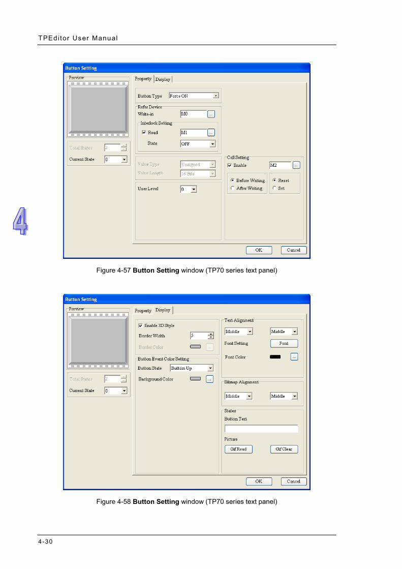
TPEditor User Manual
4-30
Figure 4-57 Button Setting window (TP70 series text panel)
Figure 4-58 Button Setting window (TP70 series text panel)
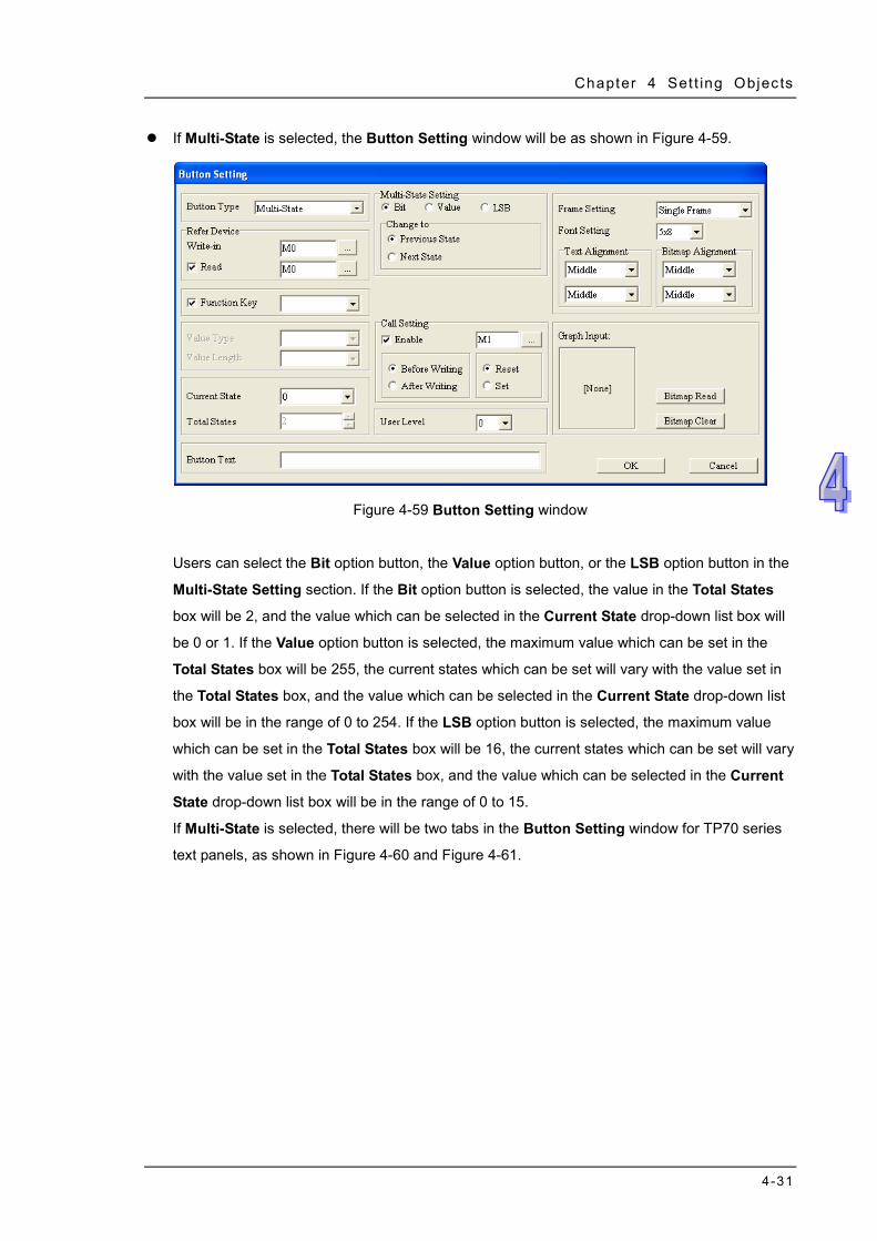
Chapter 4 Set t ing Objects
4-31
If Multi-State is selected, the Button Setting window will be as shown in Figure 4-59.
Figure 4-59 Button Setting window
Users can select the Bit option button, the Value option button, or the LSB option button in the
Multi-State Setting section. If the Bit option button is selected, the value in the Total States
box will be 2, and the value which can be selected in the Current State drop-down list box will
be 0 or 1. If the Value option button is selected, the maximum value which can be set in the
Total States box will be 255, the current states which can be set will vary with the value set in
the Total States box, and the value which can be selected in the Current State drop-down list
box will be in the range of 0 to 254. If the LSB option button is selected, the maximum value
which can be set in the Total States box will be 16, the current states which can be set will vary
with the value set in the Total States box, and the value which can be selected in the Current
State drop-down list box will be in the range of 0 to 15.
If Multi-State is selected, there will be two tabs in the Button Setting window for TP70 series
text panels, as shown in Figure 4-60 and Figure 4-61.

TPEditor User Manual
4-32
Figure 4-60 Button Setting window (TP70 series text panel)
Figure 4-61 Button Setting window (TP70 series text panel)
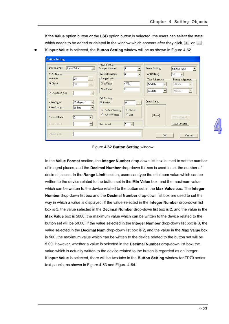
Chapter 4 Set t ing Objects
4-33
If the Value option button or the LSB option button is selected, the users can select the state
which needs to be added or deleted in the window which appears after they click or .
If Input Value is selected, the Button Setting window will be as shown in Figure 4-62.
Figure 4-62 Button Setting window
In the Value Format section, the Integer Number drop-down list box is used to set the number
of integral places, and the Decimal Number drop-down list box is used to set the number of
decimal places. In the Range Limit section, users can type the minimum value which can be
written to the device related to the button set in the Min Value box, and the maximum value
which can be written to the device related to the button set in the Max Value box. The Integer
Number drop-down list box and the Decimal Number drop-down list box are used to set the
way in which a value is displayed. If the value selected in the Integer Number drop-down list
box is 3, the value selected in the Decimal Number drop-down list box is 2, and the value in the
Max Value box is 5000, the maximum value which can be written to the device related to the
button set will be 50.00. If the value selected in the Integer Number drop-down list box is 3, the
value selected in the Decimal Num drop-down list box is 2, and the value in the Max Value box
is 500, the maximum value which can be written to the device related to the button set will be
5.00. However, whether a value is selected in the Decimal Number drop-down list box, the
value which is actually written to the device related to the button is regarded as an integer.
If Input Value is selected, there will be two tabs in the Button Setting window for TP70 series
text panels, as shown in Figure 4-63 and Figure 4-64.
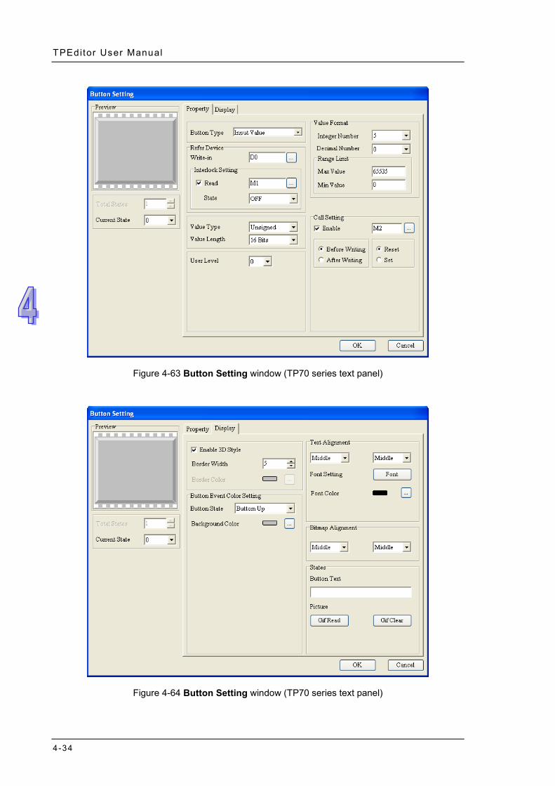
TPEditor User Manual
4-34
Figure 4-63 Button Setting window (TP70 series text panel)
Figure 4-64 Button Setting window (TP70 series text panel)
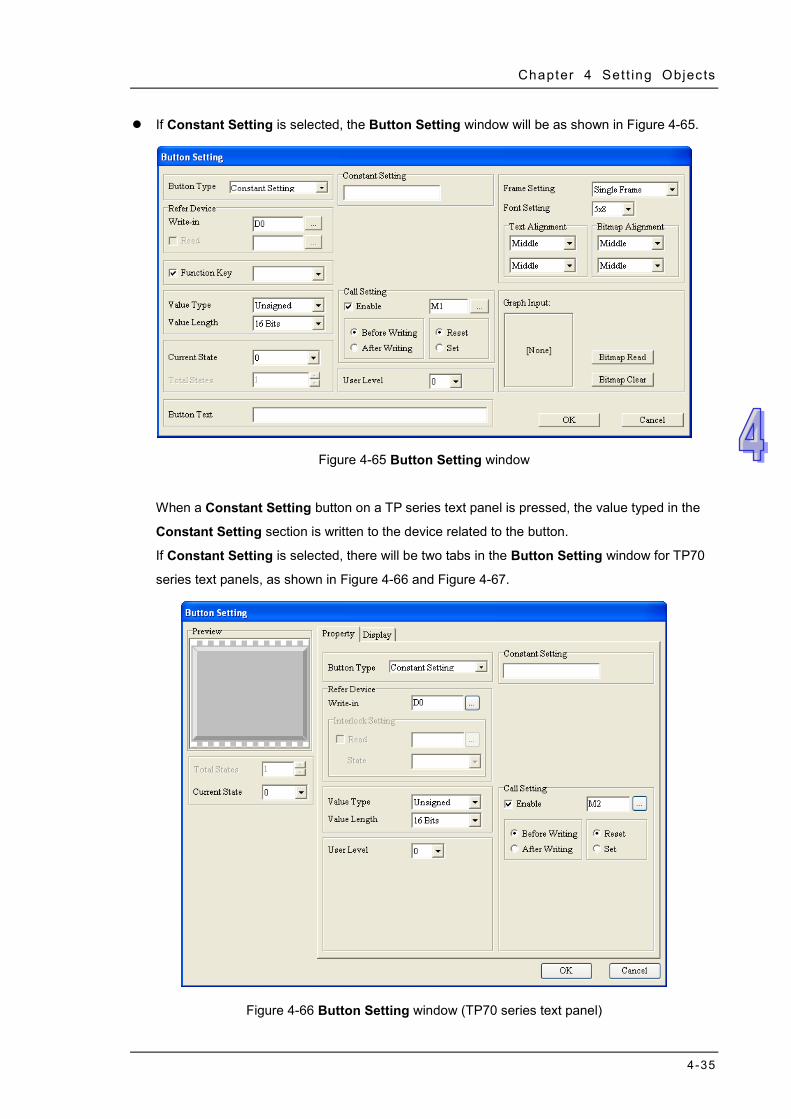
Chapter 4 Set t ing Objects
4-35
If Constant Setting is selected, the Button Setting window will be as shown in Figure 4-65.
Figure 4-65 Button Setting window
When a Constant Setting button on a TP series text panel is pressed, the value typed in the
Constant Setting section is written to the device related to the button.
If Constant Setting is selected, there will be two tabs in the Button Setting window for TP70
series text panels, as shown in Figure 4-66 and Figure 4-67.
Figure 4-66 Button Setting window (TP70 series text panel)
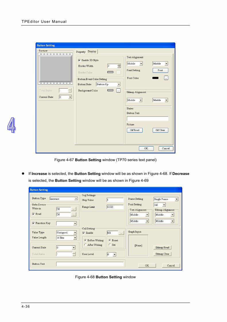
TPEditor User Manual
4-36
Figure 4-67 Button Setting window (TP70 series text panel)
If Increase is selected, the Button Setting window will be as shown in Figure 4-68. If Decrease
is selected, the Button Setting window will be as shown in Figure 4-69
Figure 4-68 Button Setting window
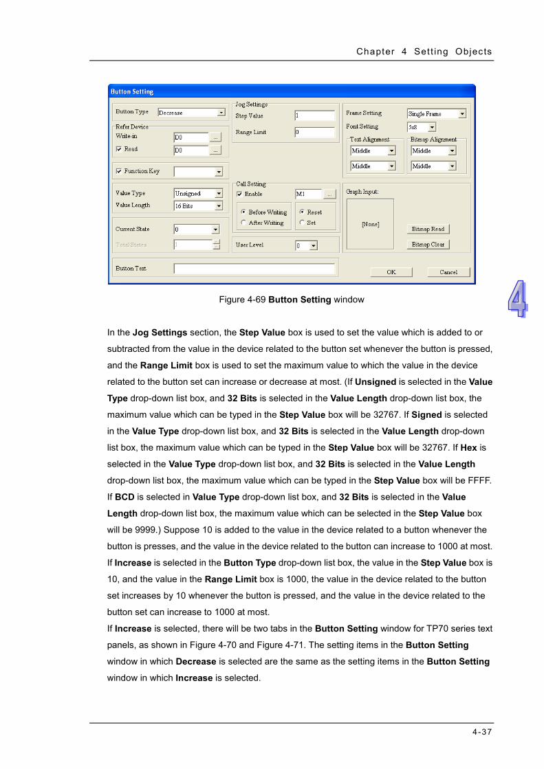
Chapter 4 Set t ing Objects
4-37
Figure 4-69 Button Setting window
In the Jog Settings section, the Step Value box is used to set the value which is added to or
subtracted from the value in the device related to the button set whenever the button is pressed,
and the Range Limit box is used to set the maximum value to which the value in the device
related to the button set can increase or decrease at most. (If Unsigned is selected in the Value
Type drop-down list box, and 32 Bits is selected in the Value Length drop-down list box, the
maximum value which can be typed in the Step Value box will be 32767. If Signed is selected
in the Value Type drop-down list box, and 32 Bits is selected in the Value Length drop-down
list box, the maximum value which can be typed in the Step Value box will be 32767. If Hex is
selected in the Value Type drop-down list box, and 32 Bits is selected in the Value Length
drop-down list box, the maximum value which can be typed in the Step Value box will be FFFF.
If BCD is selected in Value Type drop-down list box, and 32 Bits is selected in the Value
Length drop-down list box, the maximum value which can be selected in the Step Value box
will be 9999.) Suppose 10 is added to the value in the device related to a button whenever the
button is presses, and the value in the device related to the button can increase to 1000 at most.
If Increase is selected in the Button Type drop-down list box, the value in the Step Value box is
10, and the value in the Range Limit box is 1000, the value in the device related to the button
set increases by 10 whenever the button is pressed, and the value in the device related to the
button set can increase to 1000 at most.
If Increase is selected, there will be two tabs in the Button Setting window for TP70 series text
panels, as shown in Figure 4-70 and Figure 4-71. The setting items in the Button Setting
window in which Decrease is selected are the same as the setting items in the Button Setting
window in which Increase is selected.

TPEditor User Manual
4-38
Figure 4-70 Button Setting window (TP70 series text panel)
Figure 4-71 Button Setting window (TP70 series text panel)
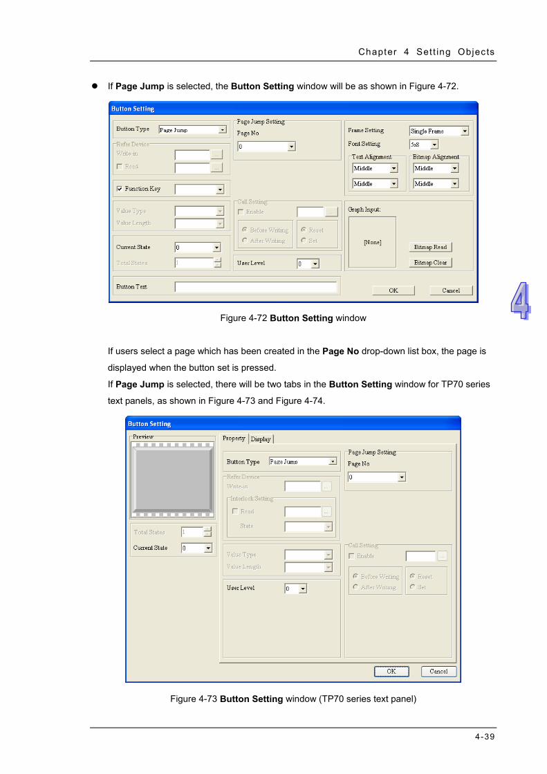
Chapter 4 Set t ing Objects
4-39
If Page Jump is selected, the Button Setting window will be as shown in Figure 4-72.
Figure 4-72 Button Setting window
If users select a page which has been created in the Page No drop-down list box, the page is
displayed when the button set is pressed.
If Page Jump is selected, there will be two tabs in the Button Setting window for TP70 series
text panels, as shown in Figure 4-73 and Figure 4-74.
Figure 4-73 Button Setting window (TP70 series text panel)
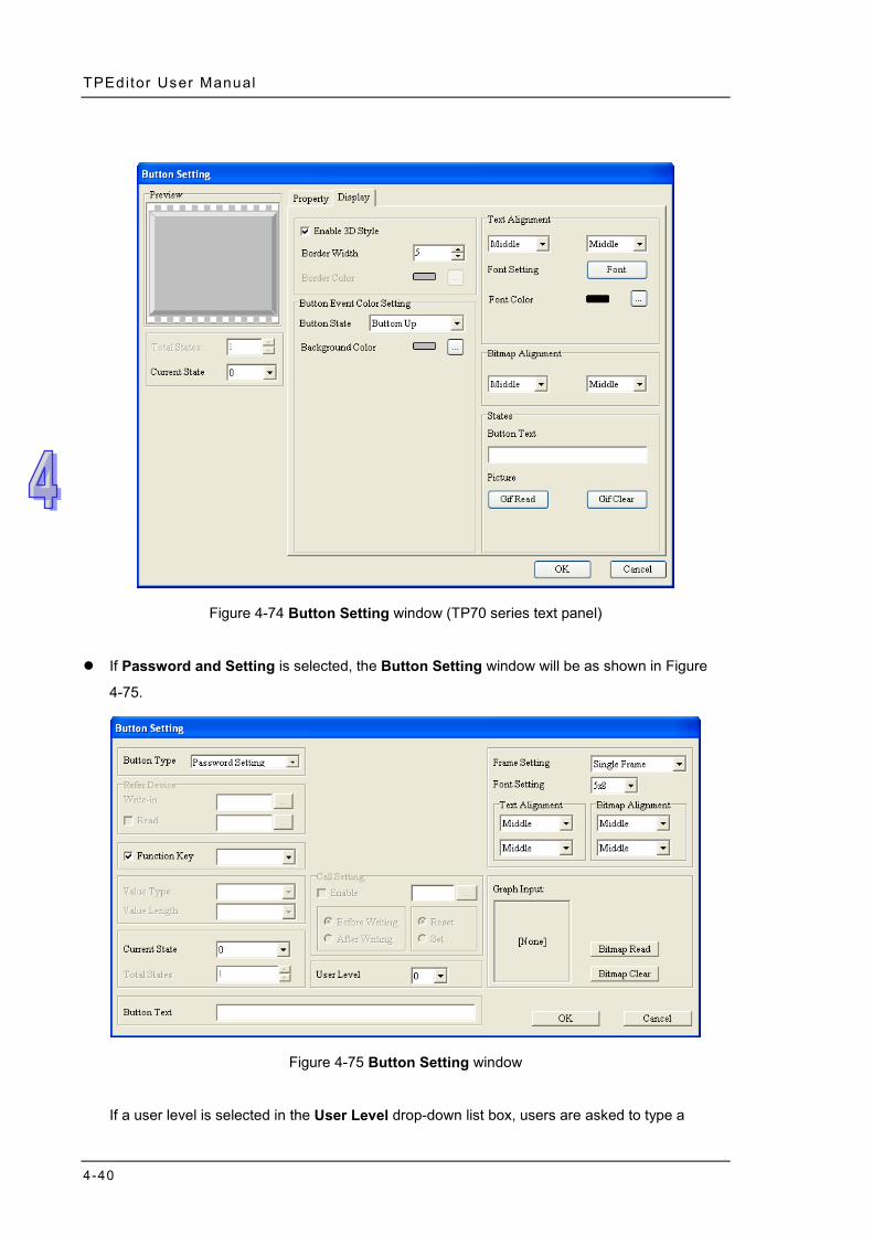
TPEditor User Manual
4-40
Figure 4-74 Button Setting window (TP70 series text panel)
If Password and Setting is selected, the Button Setting window will be as shown in Figure
4-75.
Figure 4-75 Button Setting window
If a user level is selected in the User Level drop-down list box, users are asked to type a
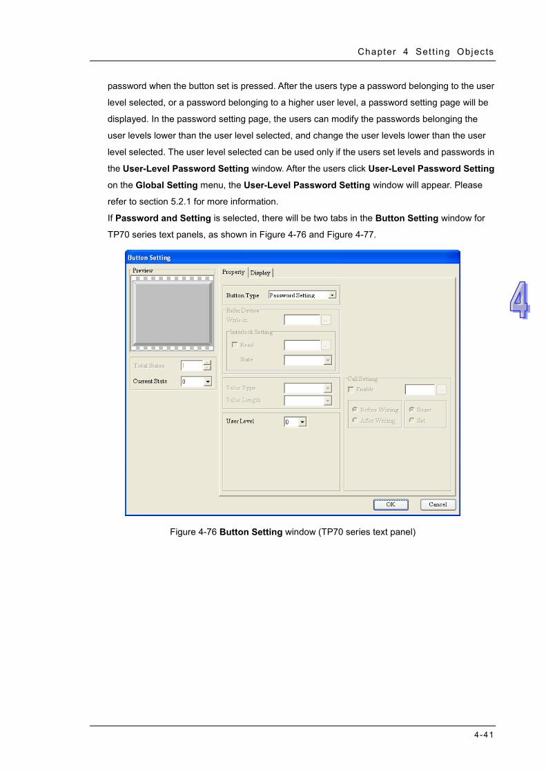
Chapter 4 Set t ing Objects
4-41
password when the button set is pressed. After the users type a password belonging to the user
level selected, or a password belonging to a higher user level, a password setting page will be
displayed. In the password setting page, the users can modify the passwords belonging the
user levels lower than the user level selected, and change the user levels lower than the user
level selected. The user level selected can be used only if the users set levels and passwords in
the User-Level Password Setting window. After the users click User-Level Password Setting
on the Global Setting menu, the User-Level Password Setting window will appear. Please
refer to section 5.2.1 for more information.
If Password and Setting is selected, there will be two tabs in the Button Setting window for
TP70 series text panels, as shown in Figure 4-76 and Figure 4-77.
Figure 4-76 Button Setting window (TP70 series text panel)

TPEditor User Manual
4-42
Figure 4-77 Button Setting window (TP70 series text panel)
If Screen Scroll is selected, the Button Setting window will be as shown in Figure 4-78.
Figure 4-78 Button Setting window
Users can select Scroll Up or Scroll Down in the Scroll Type drop-down list box. They can
select the number of lines which will be scrolled in the Scroll Lines box.
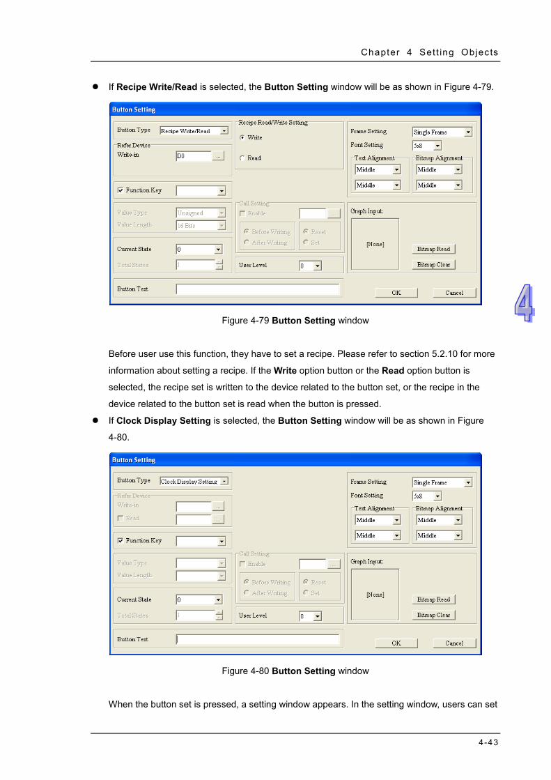
Chapter 4 Set t ing Objects
4-43
If Recipe Write/Read is selected, the Button Setting window will be as shown in Figure 4-79.
Figure 4-79 Button Setting window
Before user use this function, they have to set a recipe. Please refer to section 5.2.10 for more
information about setting a recipe. If the Write option button or the Read option button is
selected, the recipe set is written to the device related to the button set, or the recipe in the
device related to the button set is read when the button is pressed.
If Clock Display Setting is selected, the Button Setting window will be as shown in Figure
4-80.
Figure 4-80 Button Setting window
When the button set is pressed, a setting window appears. In the setting window, users can set
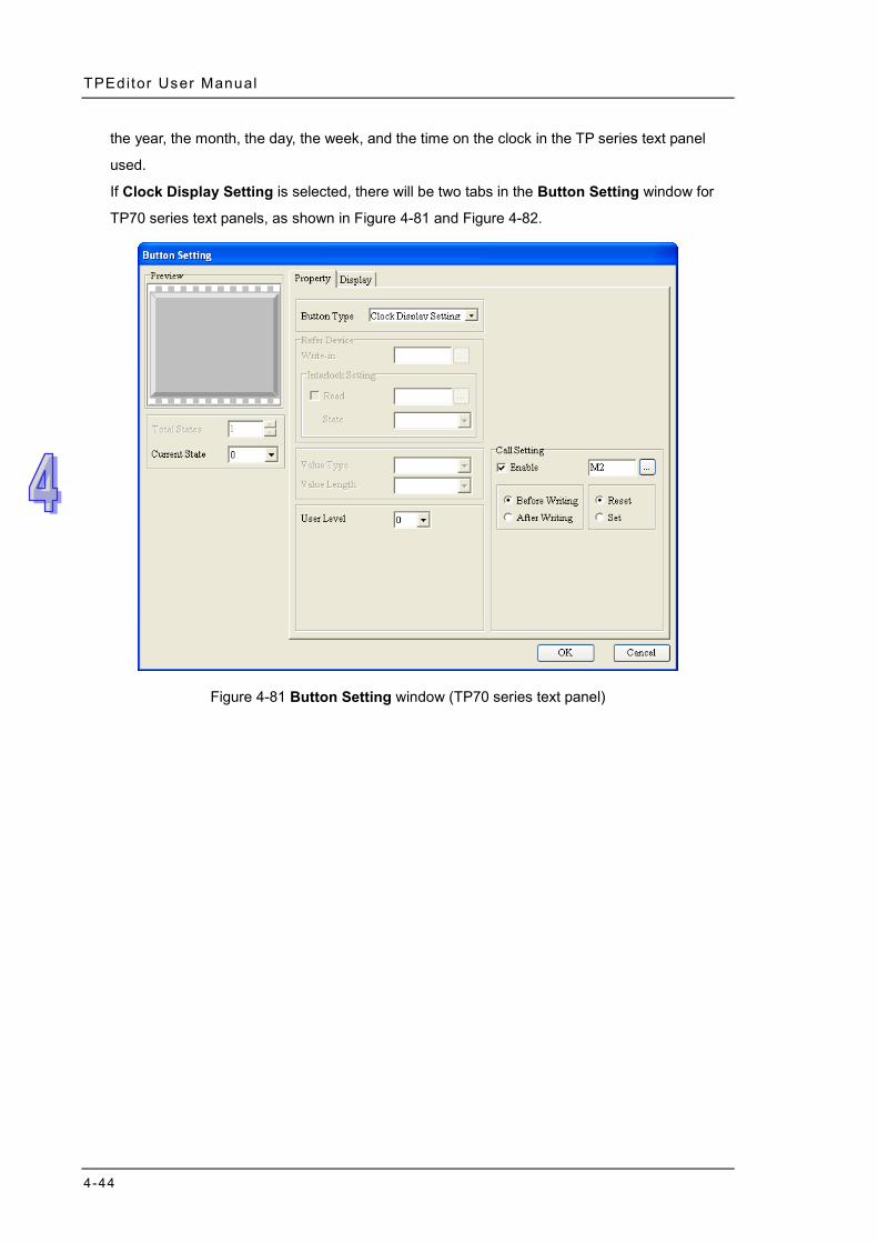
TPEditor User Manual
4-44
the year, the month, the day, the week, and the time on the clock in the TP series text panel
used.
If Clock Display Setting is selected, there will be two tabs in the Button Setting window for
TP70 series text panels, as shown in Figure 4-81 and Figure 4-82.
Figure 4-81 Button Setting window (TP70 series text panel)
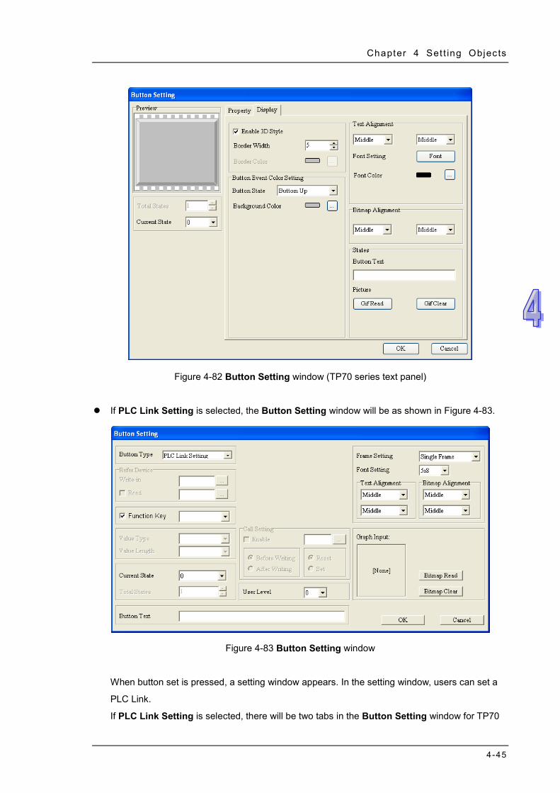
Chapter 4 Set t ing Objects
4-45
Figure 4-82 Button Setting window (TP70 series text panel)
If PLC Link Setting is selected, the Button Setting window will be as shown in Figure 4-83.
Figure 4-83 Button Setting window
When button set is pressed, a setting window appears. In the setting window, users can set a
PLC Link.
If PLC Link Setting is selected, there will be two tabs in the Button Setting window for TP70
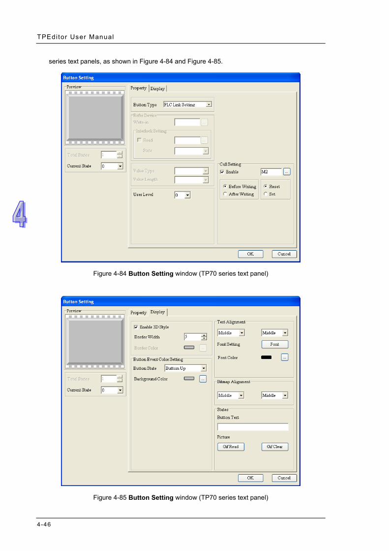
TPEditor User Manual
4-46
series text panels, as shown in Figure 4-84 and Figure 4-85.
Figure 4-84 Button Setting window (TP70 series text panel)
Figure 4-85 Button Setting window (TP70 series text panel)
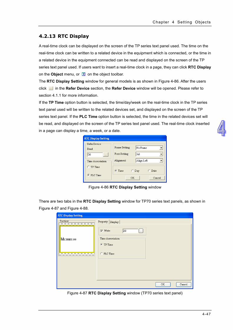
Chapter 4 Set t ing Objects
4-47
4.2.13 RTC Display
A real-time clock can be displayed on the screen of the TP series text panel used. The time on the
real-time clock can be written to a related device in the equipment which is connected, or the time in
a related device in the equipment connected can be read and displayed on the screen of the TP
series text panel used. If users want to insert a real-time clock in a page, they can click RTC Display
on the Object menu, or on the object toolbar.
The RTC Display Setting window for general models is as shown in Figure 4-86. After the users
click in the Refer Device section, the Refer Device window will be opened. Please refer to
section 4.1.1 for more information.
If the TP Time option button is selected, the time/day/week on the real-time clock in the TP series
text panel used will be written to the related devices set, and displayed on the screen of the TP
series text panel. If the PLC Time option button is selected, the time in the related devices set will
be read, and displayed on the screen of the TP series text panel used. The real-time clock inserted
in a page can display a time, a week, or a date.
Figure 4-86 RTC Display Setting window
There are two tabs in the RTC Display Setting window for TP70 series text panels, as shown in
Figure 4-87 and Figure 4-88.
Figure 4-87 RTC Display Setting window (TP70 series text panel)
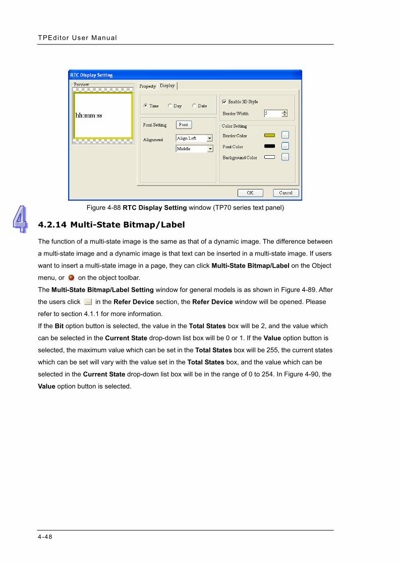
TPEditor User Manual
4-48
Figure 4-88 RTC Display Setting window (TP70 series text panel)
4.2.14 Multi-State Bitmap/Label
The function of a multi-state image is the same as that of a dynamic image. The difference between
a multi-state image and a dynamic image is that text can be inserted in a multi-state image. If users
want to insert a multi-state image in a page, they can click Multi-State Bitmap/Label on the Object
menu, or on the object toolbar.
The Multi-State Bitmap/Label Setting window for general models is as shown in Figure 4-89. After
the users click in the Refer Device section, the Refer Device window will be opened. Please
refer to section 4.1.1 for more information.
If the Bit option button is selected, the value in the Total States box will be 2, and the value which
can be selected in the Current State drop-down list box will be 0 or 1. If the Value option button is
selected, the maximum value which can be set in the Total States box will be 255, the current states
which can be set will vary with the value set in the Total States box, and the value which can be
selected in the Current State drop-down list box will be in the range of 0 to 254. In Figure 4-90, the
Value option button is selected.
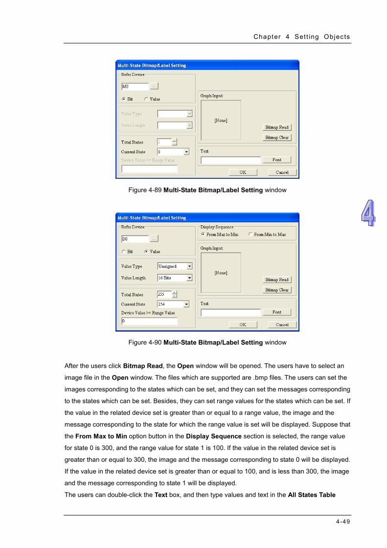
Chapter 4 Set t ing Objects
4-49
Figure 4-89 Multi-State Bitmap/Label Setting window
Figure 4-90 Multi-State Bitmap/Label Setting window
After the users click Bitmap Read, the Open window will be opened. The users have to select an
image file in the Open window. The files which are supported are .bmp files. The users can set the
images corresponding to the states which can be set, and they can set the messages corresponding
to the states which can be set. Besides, they can set range values for the states which can be set. If
the value in the related device set is greater than or equal to a range value, the image and the
message corresponding to the state for which the range value is set will be displayed. Suppose that
the From Max to Min option button in the Display Sequence section is selected, the range value
for state 0 is 300, and the range value for state 1 is 100. If the value in the related device set is
greater than or equal to 300, the image and the message corresponding to state 0 will be displayed.
If the value in the related device set is greater than or equal to 100, and is less than 300, the image
and the message corresponding to state 1 will be displayed.
The users can double-click the Text box, and then type values and text in the All States Table
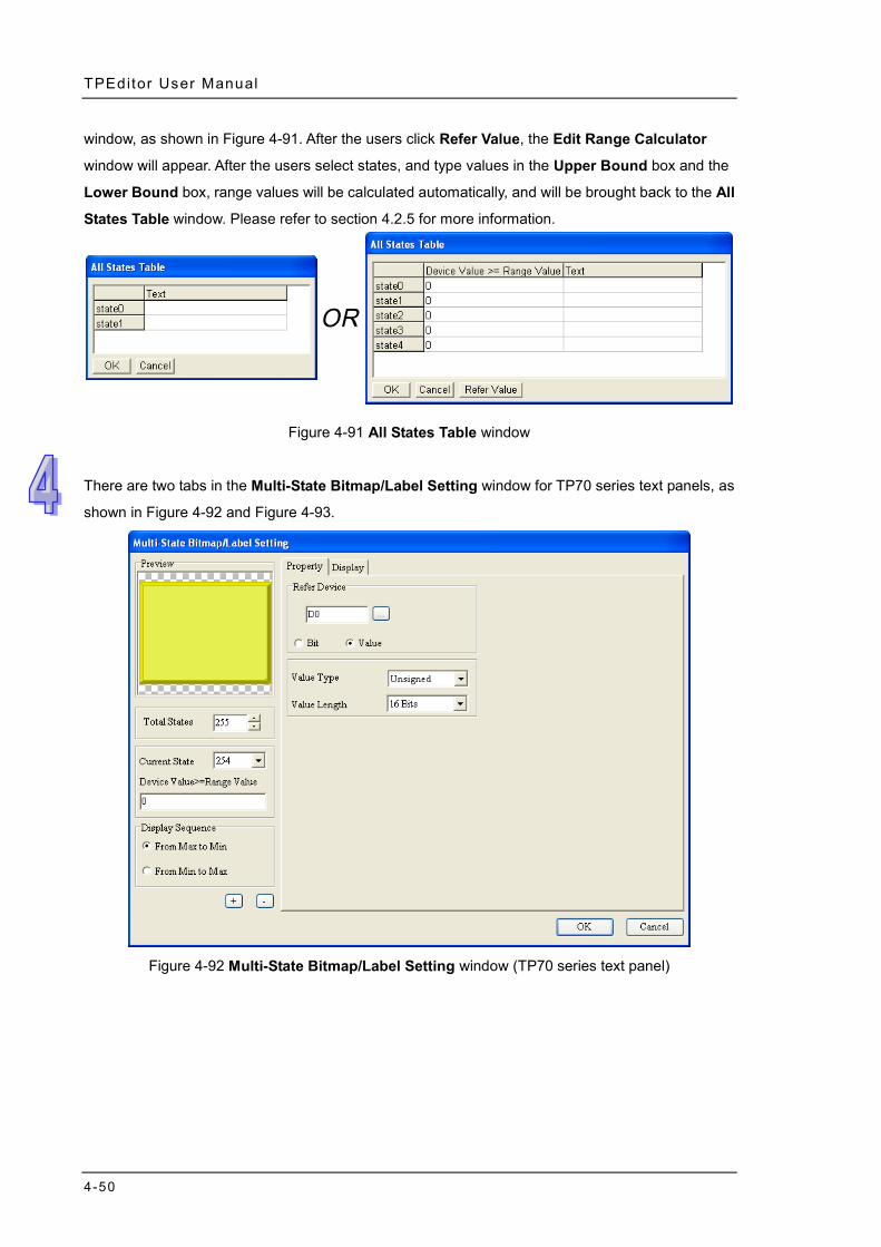
TPEditor User Manual
4-50
window, as shown in Figure 4-91. After the users click Refer Value, the Edit Range Calculator
window will appear. After the users select states, and type values in the Upper Bound box and the
Lower Bound box, range values will be calculated automatically, and will be brought back to the All
States Table window. Please refer to section 4.2.5 for more information.
Figure 4-91 All States Table window
There are two tabs in the Multi-State Bitmap/Label Setting window for TP70 series text panels, as
shown in Figure 4-92 and Figure 4-93.
Figure 4-92 Multi-State Bitmap/Label Setting window (TP70 series text panel)
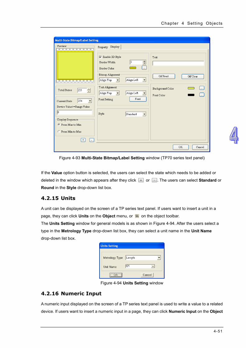
Chapter 4 Set t ing Objects
4-51
Figure 4-93 Multi-State Bitmap/Label Setting window (TP70 series text panel)
If the Value option button is selected, the users can select the state which needs to be added or
deleted in the window which appears after they click or . The users can select Standard or
Round in the Style drop-down list box.
4.2.15 Units
A unit can be displayed on the screen of a TP series text panel. If users want to insert a unit in a
page, they can click Units on the Object menu, or on the object toolbar.
The Units Setting window for general models is as shown in Figure 4-94. After the users select a
type in the Metrology Type drop-down list box, they can select a unit name in the Unit Name
drop-down list box.
Figure 4-94 Units Setting window
4.2.16 Numeric Input
A numeric input displayed on the screen of a TP series text panel is used to write a value to a related
device. If users want to insert a numeric input in a page, they can click Numeric Input on the Object
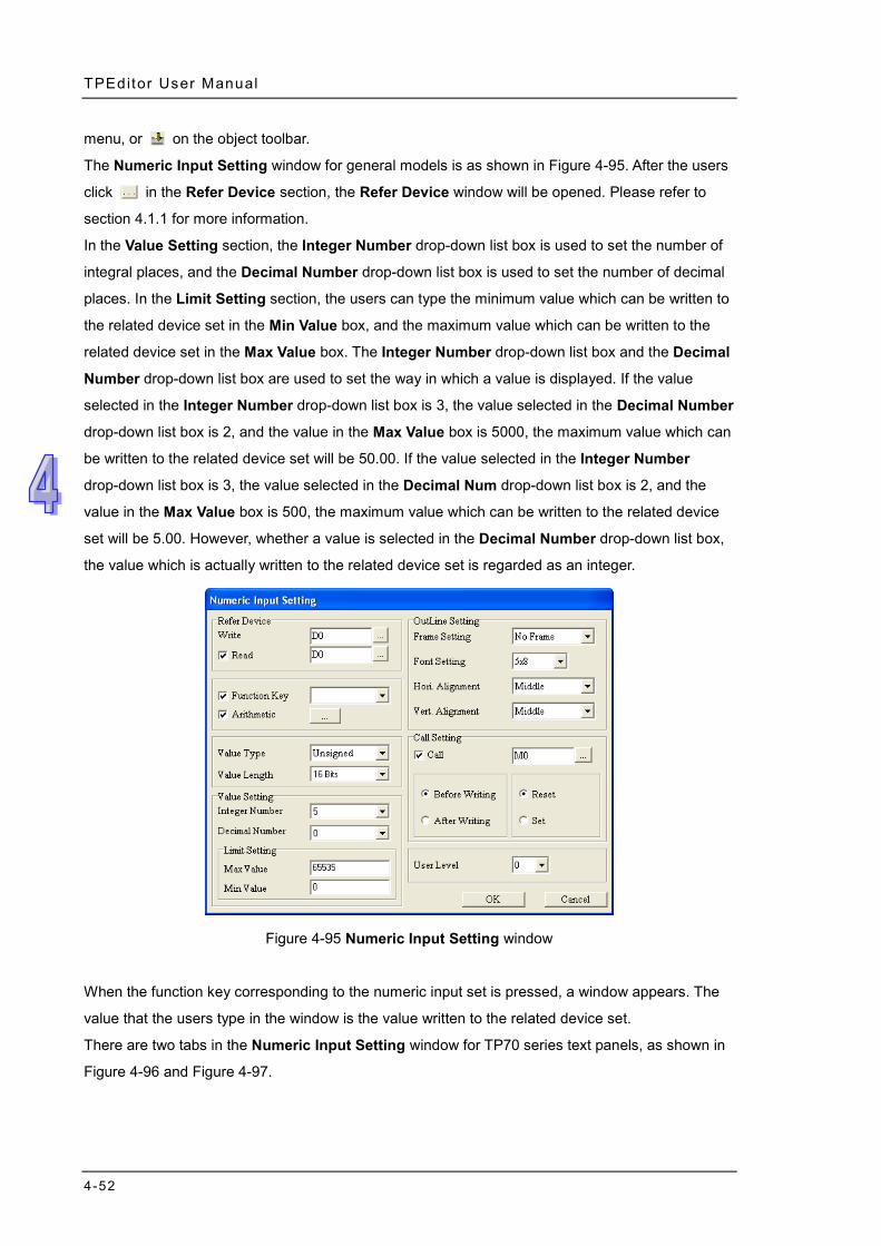
TPEditor User Manual
4-52
menu, or on the object toolbar.
The Numeric Input Setting window for general models is as shown in Figure 4-95. After the users
click in the Refer Device section, the Refer Device window will be opened. Please refer to
section 4.1.1 for more information.
In the Value Setting section, the Integer Number drop-down list box is used to set the number of
integral places, and the Decimal Number drop-down list box is used to set the number of decimal
places. In the Limit Setting section, the users can type the minimum value which can be written to
the related device set in the Min Value box, and the maximum value which can be written to the
related device set in the Max Value box. The Integer Number drop-down list box and the Decimal
Number drop-down list box are used to set the way in which a value is displayed. If the value
selected in the Integer Number drop-down list box is 3, the value selected in the Decimal Number
drop-down list box is 2, and the value in the Max Value box is 5000, the maximum value which can
be written to the related device set will be 50.00. If the value selected in the Integer Number
drop-down list box is 3, the value selected in the Decimal Num drop-down list box is 2, and the
value in the Max Value box is 500, the maximum value which can be written to the related device
set will be 5.00. However, whether a value is selected in the Decimal Number drop-down list box,
the value which is actually written to the related device set is regarded as an integer.
Figure 4-95 Numeric Input Setting window
When the function key corresponding to the numeric input set is pressed, a window appears. The
value that the users type in the window is the value written to the related device set.
There are two tabs in the Numeric Input Setting window for TP70 series text panels, as shown in
Figure 4-96 and Figure 4-97.
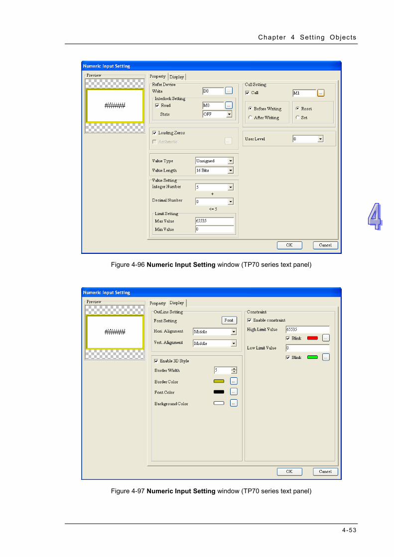
Chapter 4 Set t ing Objects
4-53
Figure 4-96 Numeric Input Setting window (TP70 series text panel)
Figure 4-97 Numeric Input Setting window (TP70 series text panel)
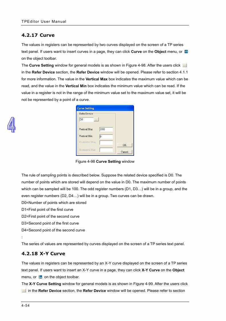
TPEditor User Manual
4-54
4.2.17 Curve
The values in registers can be represented by two curves displayed on the screen of a TP series
text panel. If users want to insert curves in a page, they can click Curve on the Object menu, or
on the object toolbar.
The Curve Setting window for general models is as shown in Figure 4-98. After the users click
in the Refer Device section, the Refer Device window will be opened. Please refer to section 4.1.1
for more information. The value in the Vertical Max box indicates the maximum value which can be
read, and the value in the Vertical Min box indicates the minimum value which can be read. If the
value in a register is not in the range of the minimum value set to the maximum value set, it will be
not be represented by a point of a curve.
Figure 4-98 Curve Setting window
The rule of sampling points is described below. Suppose the related device specified is D0. The
number of points which are stored will depend on the value in D0. The maximum number of points
which can be sampled will be 100. The odd register numbers (D1, D3…) will be in a group, and the
even register numbers (D2, D4…) will be in a group. Two curves can be drawn.
D0=Number of points which are stored
D1=First point of the first curve
D2=First point of the second curve
D3=Second point of the first curve
D4=Second point of the second curve
:
The series of values are represented by curves displayed on the screen of a TP series text panel.
4.2.18 X-Y Curve
The values in registers can be represented by an X-Y curve displayed on the screen of a TP series
text panel. If users want to insert an X-Y curve in a page, they can click X-Y Curve on the Object
menu, or on the object toolbar.
The X-Y Curve Setting window for general models is as shown in Figure 4-99. After the users click
in the Refer Device section, the Refer Device window will be opened. Please refer to section
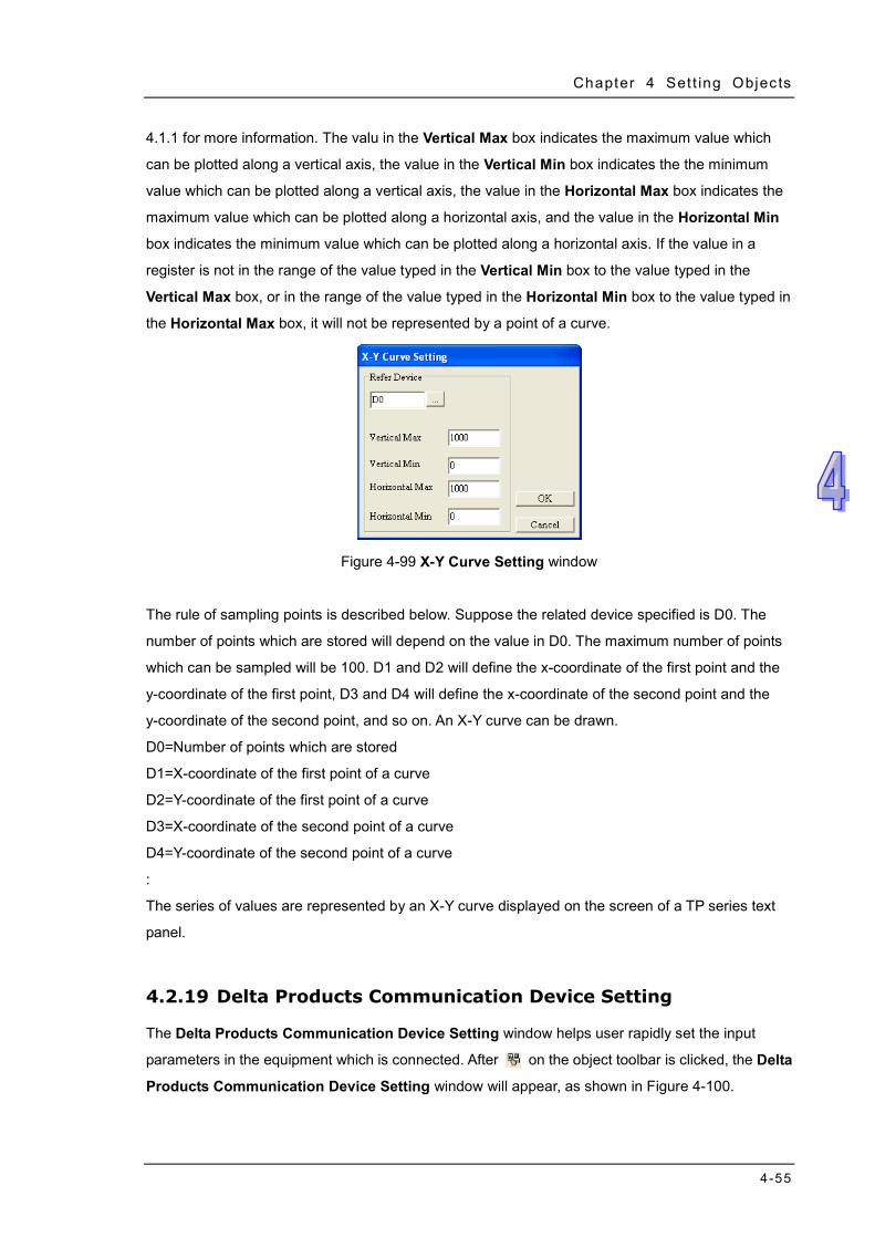
Chapter 4 Set t ing Objects
4-55
4.1.1 for more information. The valu in the Vertical Max box indicates the maximum value which
can be plotted along a vertical axis, the value in the Vertical Min box indicates the the minimum
value which can be plotted along a vertical axis, the value in the Horizontal Max box indicates the
maximum value which can be plotted along a horizontal axis, and the value in the Horizontal Min
box indicates the minimum value which can be plotted along a horizontal axis. If the value in a
register is not in the range of the value typed in the Vertical Min box to the value typed in the
Vertical Max box, or in the range of the value typed in the Horizontal Min box to the value typed in
the Horizontal Max box, it will not be represented by a point of a curve.
Figure 4-99 X-Y Curve Setting window
The rule of sampling points is described below. Suppose the related device specified is D0. The
number of points which are stored will depend on the value in D0. The maximum number of points
which can be sampled will be 100. D1 and D2 will define the x-coordinate of the first point and the
y-coordinate of the first point, D3 and D4 will define the x-coordinate of the second point and the
y-coordinate of the second point, and so on. An X-Y curve can be drawn.
D0=Number of points which are stored
D1=X-coordinate of the first point of a curve
D2=Y-coordinate of the first point of a curve
D3=X-coordinate of the second point of a curve
D4=Y-coordinate of the second point of a curve
:
The series of values are represented by an X-Y curve displayed on the screen of a TP series text
panel.
4.2.19 Delta Products Communication Device Setting
The Delta Products Communication Device Setting window helps user rapidly set the input
parameters in the equipment which is connected. After on the object toolbar is clicked, the Delta
Products Communication Device Setting window will appear, as shown in Figure 4-100.
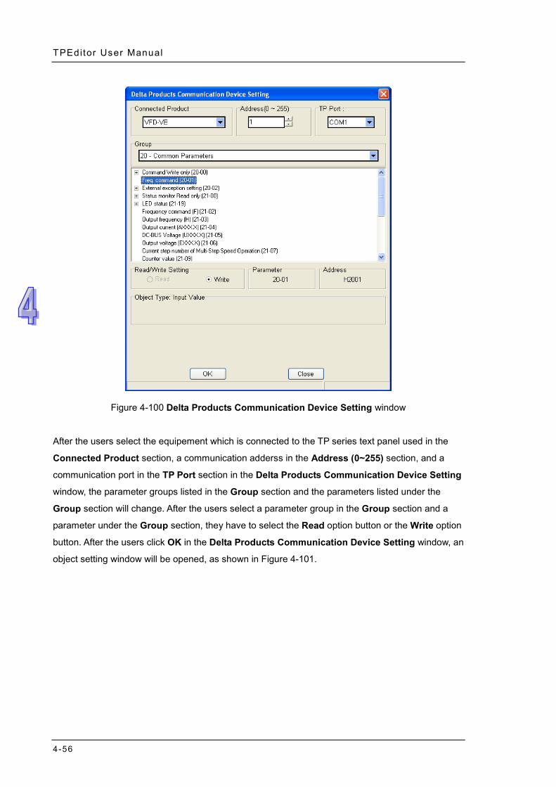
TPEditor User Manual
4-56
Figure 4-100 Delta Products Communication Device Setting window
After the users select the equipement which is connected to the TP series text panel used in the
Connected Product section, a communication adderss in the Address (0~255) section, and a
communication port in the TP Port section in the Delta Products Communication Device Setting
window, the parameter groups listed in the Group section and the parameters listed under the
Group section will change. After the users select a parameter group in the Group section and a
parameter under the Group section, they have to select the Read option button or the Write option
button. After the users click OK in the Delta Products Communication Device Setting window, an
object setting window will be opened, as shown in Figure 4-101.
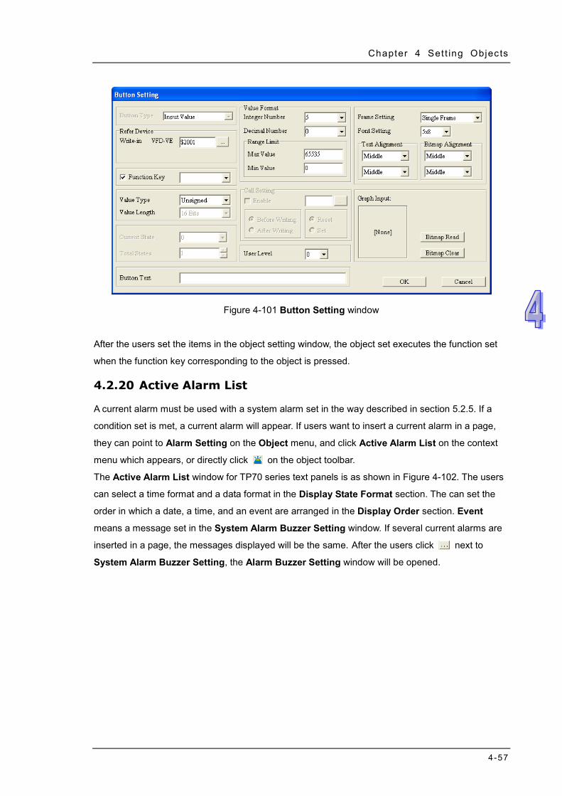
Chapter 4 Set t ing Objects
4-57
Figure 4-101 Button Setting window
After the users set the items in the object setting window, the object set executes the function set
when the function key corresponding to the object is pressed.
4.2.20 Active Alarm List
A current alarm must be used with a system alarm set in the way described in section 5.2.5. If a
condition set is met, a current alarm will appear. If users want to insert a current alarm in a page,
they can point to Alarm Setting on the Object menu, and click Active Alarm List on the context
menu which appears, or directly click on the object toolbar.
The Active Alarm List window for TP70 series text panels is as shown in Figure 4-102. The users
can select a time format and a data format in the Display State Format section. The can set the
order in which a date, a time, and an event are arranged in the Display Order section. Event
means a message set in the System Alarm Buzzer Setting window. If several current alarms are
inserted in a page, the messages displayed will be the same. After the users click next to
System Alarm Buzzer Setting, the Alarm Buzzer Setting window will be opened.
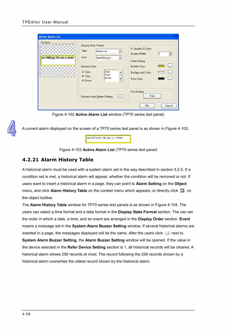
TPEditor User Manual
4-58
Figure 4-102 Active Alarm List window (TP70 series text panel)
A current alarm displayed on the screen of a TP70 series text panel is as shown in Figure 4-103.
Figure 4-103 Active Alarm List (TP70 series text panel)
4.2.21 Alarm History Table
A historical alarm must be used with a system alarm set in the way described in section 5.2.5. If a
condition set is met, a historical alarm will appear, whether the condition will be removed or not. If
users want to insert a historical alarm in a page, they can point to Alarm Setting on the Object
menu, and click Alarm History Table on the context menu which appears, or directly click on
the object toolbar.
The Alarm History Table window for TP70 series text panels is as shown in Figure 4-104. The
users can select a time format and a data format in the Display State Format section. The can set
the order in which a date, a time, and an event are arranged in the Display Order section. Event
means a message set in the System Alarm Buzzer Setting window. If several historical alarms are
inserted in a page, the messages displayed will be the same. After the users click next to
System Alarm Buzzer Setting, the Alarm Buzzer Setting window will be opened. If the value in
the device selected in the Refer Device Setting section is 1, all historical records will be cleared. A
historical alarm shows 256 records at most. The record following the 256 records shown by a
historical alarm overwrites the oldest record shown by the historical alarm.
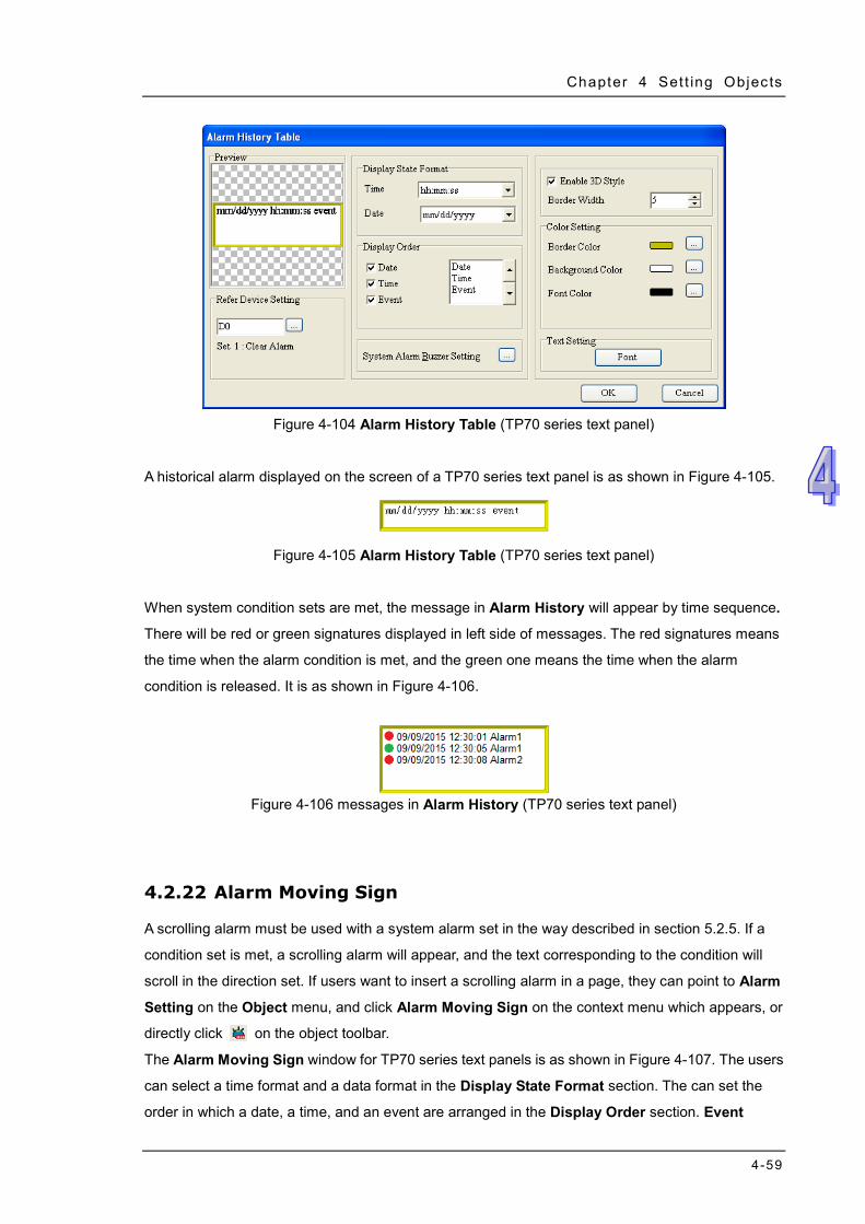
Chapter 4 Set t ing Objects
4-59
Figure 4-104 Alarm History Table (TP70 series text panel)
A historical alarm displayed on the screen of a TP70 series text panel is as shown in Figure 4-105.
Figure 4-105 Alarm History Table (TP70 series text panel)
When system condition sets are met, the message in Alarm History will appear by time sequence.
There will be red or green signatures displayed in left side of messages. The red signatures means
the time when the alarm condition is met, and the green one means the time when the alarm
condition is released. It is as shown in Figure 4-106.
Figure 4-106 messages in Alarm History (TP70 series text panel)
4.2.22 Alarm Moving Sign
A scrolling alarm must be used with a system alarm set in the way described in section 5.2.5. If a
condition set is met, a scrolling alarm will appear, and the text corresponding to the condition will
scroll in the direction set. If users want to insert a scrolling alarm in a page, they can point to Alarm
Setting on the Object menu, and click Alarm Moving Sign on the context menu which appears, or
directly click on the object toolbar.
The Alarm Moving Sign window for TP70 series text panels is as shown in Figure 4-107. The users
can select a time format and a data format in the Display State Format section. The can set the
order in which a date, a time, and an event are arranged in the Display Order section. Event
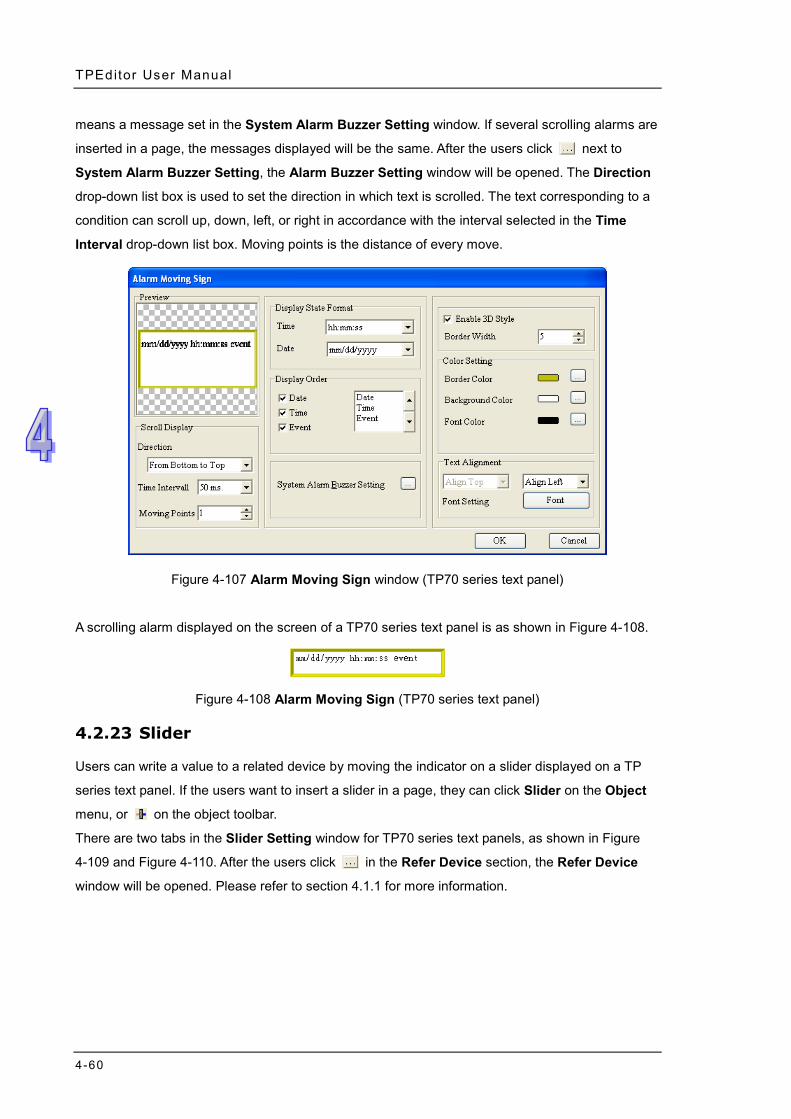
TPEditor User Manual
4-60
means a message set in the System Alarm Buzzer Setting window. If several scrolling alarms are
inserted in a page, the messages displayed will be the same. After the users click next to
System Alarm Buzzer Setting, the Alarm Buzzer Setting window will be opened. The Direction
drop-down list box is used to set the direction in which text is scrolled. The text corresponding to a
condition can scroll up, down, left, or right in accordance with the interval selected in the Time
Interval drop-down list box. Moving points is the distance of every move.
Figure 4-107 Alarm Moving Sign window (TP70 series text panel)
A scrolling alarm displayed on the screen of a TP70 series text panel is as shown in Figure 4-108.
Figure 4-108 Alarm Moving Sign (TP70 series text panel)
4.2.23 Slider
Users can write a value to a related device by moving the indicator on a slider displayed on a TP
series text panel. If the users want to insert a slider in a page, they can click Slider on the Object
menu, or on the object toolbar.
There are two tabs in the Slider Setting window for TP70 series text panels, as shown in Figure
4-109 and Figure 4-110. After the users click in the Refer Device section, the Refer Device
window will be opened. Please refer to section 4.1.1 for more information.
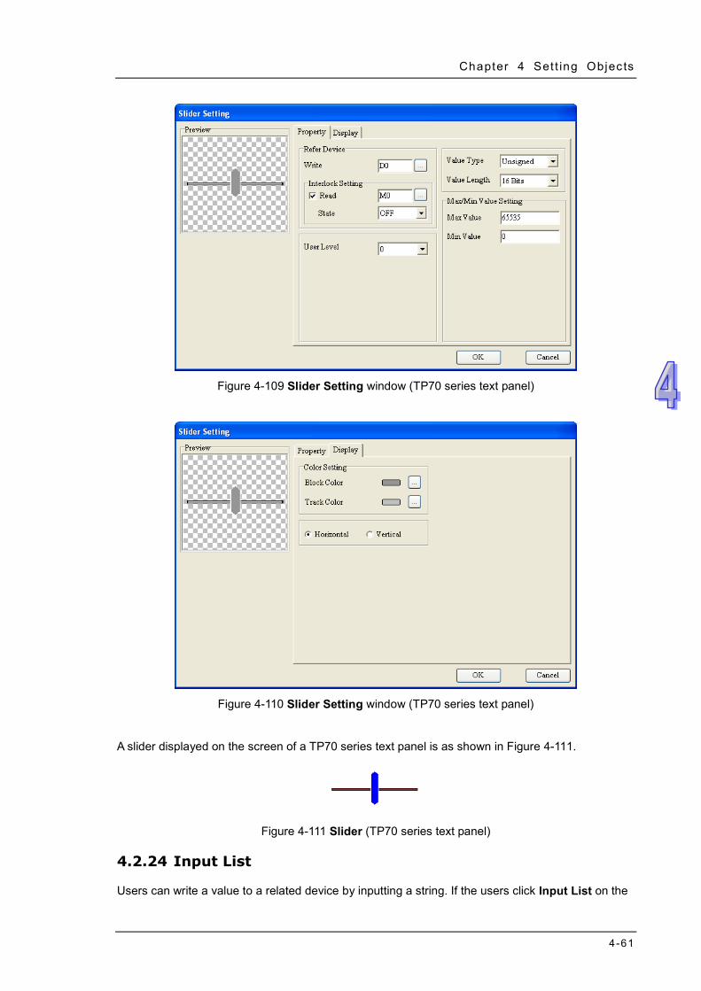
Chapter 4 Set t ing Objects
4-61
Figure 4-109 Slider Setting window (TP70 series text panel)
Figure 4-110 Slider Setting window (TP70 series text panel)
A slider displayed on the screen of a TP70 series text panel is as shown in Figure 4-111.
Figure 4-111 Slider (TP70 series text panel)
4.2.24 Input List
Users can write a value to a related device by inputting a string. If the users click Input List on the
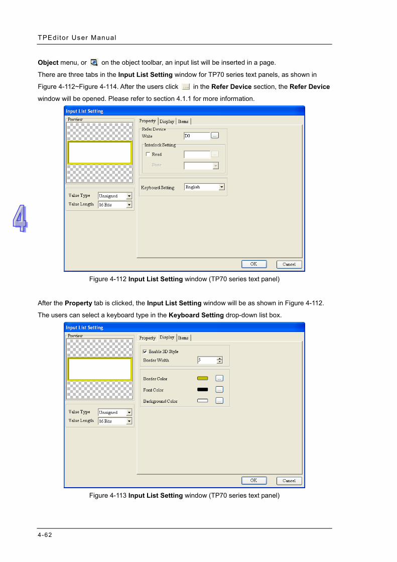
TPEditor User Manual
4-62
Object menu, or on the object toolbar, an input list will be inserted in a page.
There are three tabs in the Input List Setting window for TP70 series text panels, as shown in
Figure 4-112~Figure 4-114. After the users click in the Refer Device section, the Refer Device
window will be opened. Please refer to section 4.1.1 for more information.
Figure 4-112 Input List Setting window (TP70 series text panel)
After the Property tab is clicked, the Input List Setting window will be as shown in Figure 4-112.
The users can select a keyboard type in the Keyboard Setting drop-down list box.
Figure 4-113 Input List Setting window (TP70 series text panel)
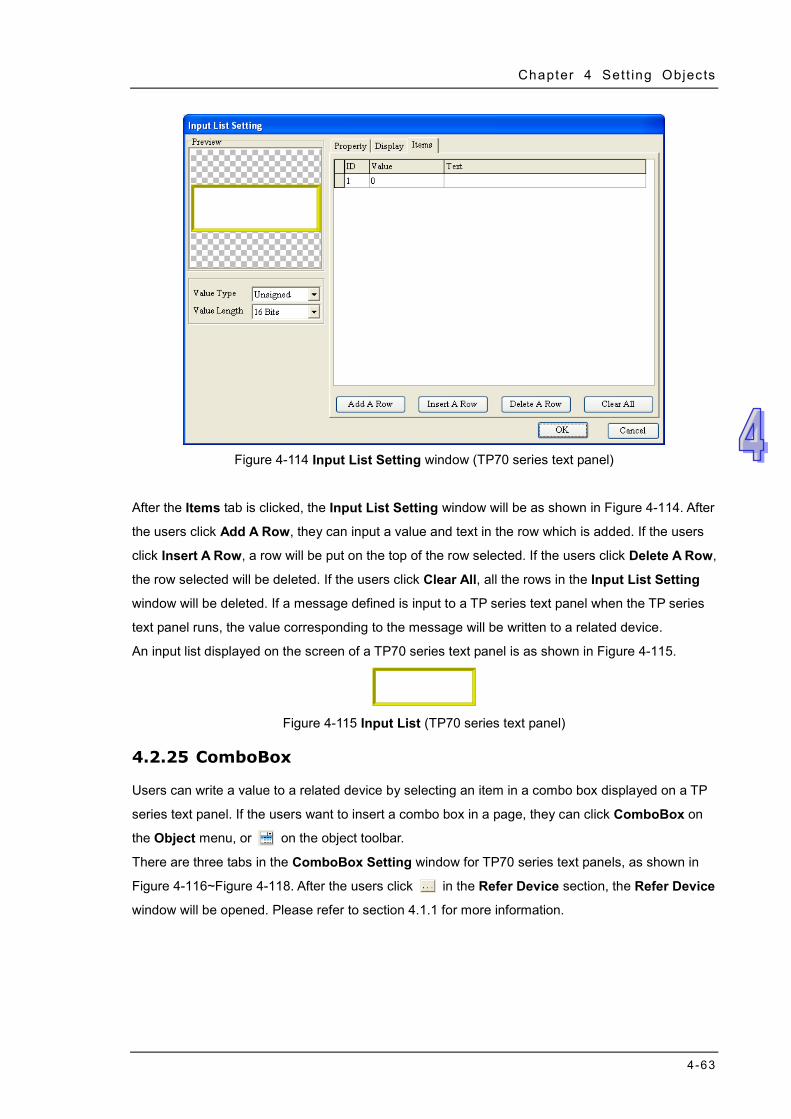
Chapter 4 Set t ing Objects
4-63
Figure 4-114 Input List Setting window (TP70 series text panel)
After the Items tab is clicked, the Input List Setting window will be as shown in Figure 4-114. After
the users click Add A Row, they can input a value and text in the row which is added. If the users
click Insert A Row, a row will be put on the top of the row selected. If the users click Delete A Row,
the row selected will be deleted. If the users click Clear All, all the rows in the Input List Setting
window will be deleted. If a message defined is input to a TP series text panel when the TP series
text panel runs, the value corresponding to the message will be written to a related device.
An input list displayed on the screen of a TP70 series text panel is as shown in Figure 4-115.
Figure 4-115 Input List (TP70 series text panel)
4.2.25 ComboBox
Users can write a value to a related device by selecting an item in a combo box displayed on a TP
series text panel. If the users want to insert a combo box in a page, they can click ComboBox on
the Object menu, or on the object toolbar.
There are three tabs in the ComboBox Setting window for TP70 series text panels, as shown in
Figure 4-116~Figure 4-118. After the users click in the Refer Device section, the Refer Device
window will be opened. Please refer to section 4.1.1 for more information.
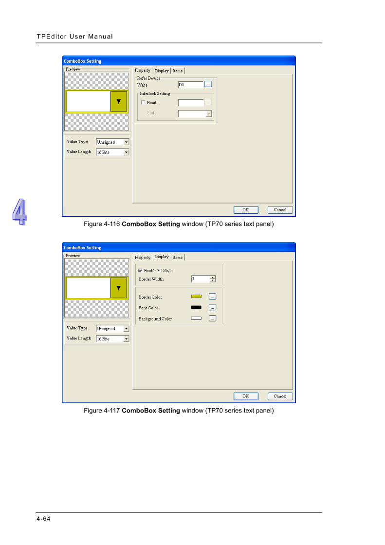
TPEditor User Manual
4-64
Figure 4-116 ComboBox Setting window (TP70 series text panel)
Figure 4-117 ComboBox Setting window (TP70 series text panel)
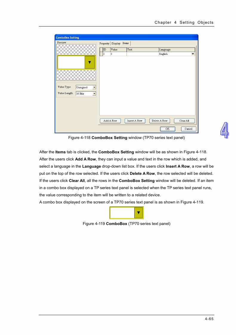
Chapter 4 Set t ing Objects
4-65
Figure 4-118 ComboBox Setting window (TP70 series text panel)
After the Items tab is clicked, the ComboBox Setting window will be as shown in Figure 4-118.
After the users click Add A Row, they can input a value and text in the row which is added, and
select a language in the Language drop-down list box. If the users click Insert A Row, a row will be
put on the top of the row selected. If the users click Delete A Row, the row selected will be deleted.
If the users click Clear All, all the rows in the ComboBox Setting window will be deleted. If an item
in a combo box displayed on a TP series text panel is selected when the TP series text panel runs,
the value corresponding to the item will be written to a related device.
A combo box displayed on the screen of a TP70 series text panel is as shown in Figure 4-119.
Figure 4-119 ComboBox (TP70 series text panel)

TPEditor User Manual
4-66
MEMO
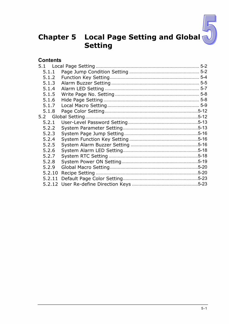
5-1
Chapter 5 Local Page Setting and Global Setting
Contents 5.1 Local Page Setting ................................................................................ 5-2
5.1.1 Page Jump Condition Setting ...................................................... 5-2 5.1.2 Function Key Setting ..................................................................... 5-4 5.1.3 Alarm Buzzer Setting .................................................................... 5-5 5.1.4 Alarm LED Setting ......................................................................... 5-7 5.1.5 Write Page No. Setting ................................................................. 5-8 5.1.6 Hide Page Setting .......................................................................... 5-8 5.1.7 Local Macro Setting ....................................................................... 5-9 5.1.8 Page Color Setting ........................................................................5-12
5.2 Global Setting .......................................................................................5-12 5.2.1 User-Level Password Setting ......................................................5-13 5.2.2 System Parameter Setting ..........................................................5-13 5.2.3 System Page Jump Setting .........................................................5-16 5.2.4 System Function Key Setting .....................................................5-16 5.2.5 System Alarm Buzzer Setting ....................................................5-16 5.2.6 System Alarm LED Setting..........................................................5-18 5.2.7 System RTC Setting .....................................................................5-18 5.2.8 System Power ON Setting ...........................................................5-19 5.2.9 Global Macro Setting ....................................................................5-20 5.2.10 Recipe Setting ...............................................................................5-20 5.2.11 Default Page Color Setting ..........................................................5-23 5.2.12 User Re-define Direction Keys ...................................................5-23
TPEditor User Manual
5-2
5.1 Local Page Setting
The Local Page Setting menu provides the functions which can be used to set pages in a TP series
text panel, e.g. Page Jump Condition Setting and Function Key Setting. Each individual page in
a TP series text panel can be set, and therefore the TP series text panel can be operated
conveniently. Please refer to section 4.1 for more information about basic setting items. Some
functions only support some models. Please refer to appendix A for more information.
5.1.1 Page Jump Condition Setting
Page Jump Condition Setting is used to set the conditions of jumping to particular pages. If the
condition of jumping to a page is met, the page will be displayed on the screen of the TP series text
panel used. After users click Page Jump Condition Setting on the Local Page Setting menu, or
right-click a page and then click Page Jump Condition Setting on the context menu which appears,
the Page Jump Condition Setting window will appear, as shown in Figure 5-1. After the users
select the Enable checkbox, they can set conditions. After the users click in the Refer Device
section, the Refer Device window will be opened. Please refer to section 4.1.1 for more information.
Figure 5-1 Page Jump Condition Setting window
After the users select the Bit option button in the Condition Setting section, they can select the
OFF option button or the ON option button in the ON/OFF Setting. The users can select a page
which has been created in the Jump Page drop-down list box. After the users click , the
condition of jumping to the page selected will be added to the box at the right side of the Page Jump
Condition Setting window. The users can add several conditions of jumping to particular pages.

Chapter 5 Local Page Set t ing and Global Set t ing
5-3
Twenty conditions at most can be added.
After the users select the Value option button in the Condition Setting section, they can set a value
in the Value Setting section. The users can type a value in the Compare Setting box, and select =,
<, >, >=, <=, or != in the Compare Setting drop-down list box. The value in the related device set
needs to be compared with the value typed in the Compare Setting box. If the users need to delete
a condition which has been added, they have to select the condition, and click . If the users
select a condition, modify the condition, and click , the condition will be changed.
Please see Figure 5-2. If the related device M0 is OFF, page 0 will be displayed on the screen of the
TP series text panel used.
Figure 5-2 Condition which is added
Please see Figure 5-3. If the value in the related device D0 is greater than 100, page 0 will be
displayed on the screen of the TP series text panel used.
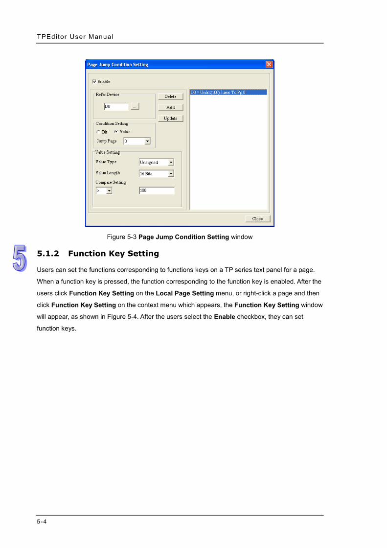
TPEditor User Manual
5-4
Figure 5-3 Page Jump Condition Setting window
5.1.2 Function Key Setting
Users can set the functions corresponding to functions keys on a TP series text panel for a page.
When a function key is pressed, the function corresponding to the function key is enabled. After the
users click Function Key Setting on the Local Page Setting menu, or right-click a page and then
click Function Key Setting on the context menu which appears, the Function Key Setting window
will appear, as shown in Figure 5-4. After the users select the Enable checkbox, they can set
function keys.
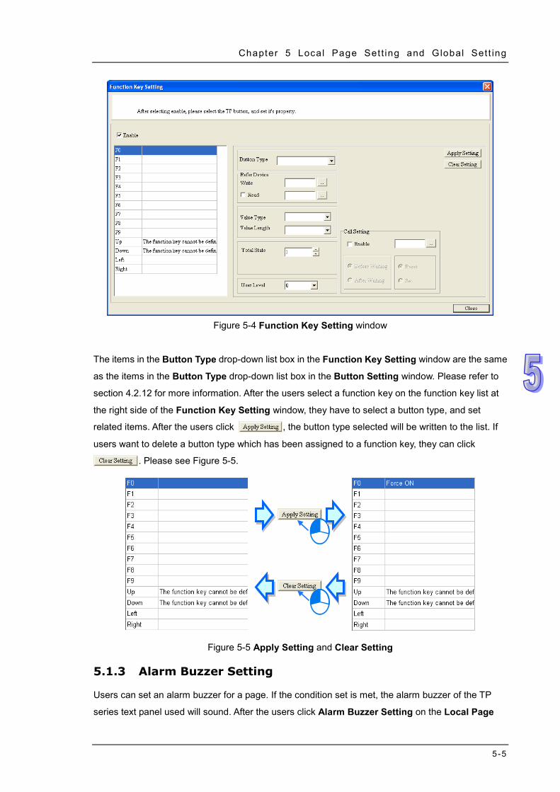
Chapter 5 Local Page Set t ing and Global Set t ing
5-5
Figure 5-4 Function Key Setting window
The items in the Button Type drop-down list box in the Function Key Setting window are the same
as the items in the Button Type drop-down list box in the Button Setting window. Please refer to
section 4.2.12 for more information. After the users select a function key on the function key list at
the right side of the Function Key Setting window, they have to select a button type, and set
related items. After the users click , the button type selected will be written to the list. If
users want to delete a button type which has been assigned to a function key, they can click
. Please see Figure 5-5.
Figure 5-5 Apply Setting and Clear Setting
5.1.3 Alarm Buzzer Setting
Users can set an alarm buzzer for a page. If the condition set is met, the alarm buzzer of the TP
series text panel used will sound. After the users click Alarm Buzzer Setting on the Local Page
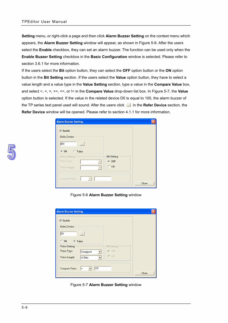
TPEditor User Manual
5-6
Setting menu, or right-click a page and then click Alarm Buzzer Setting on the context menu which
appears, the Alarm Buzzer Setting window will appear, as shown in Figure 5-6. After the users
select the Enable checkbox, they can set an alarm buzzer. The function can be used only when the
Enable Buzzer Setting checkbox in the Basic Configuration window is selected. Please refer to
section 3.6.1 for more information.
If the users select the Bit option button, they can select the OFF option button or the ON option
button in the Bit Setting section. If the users select the Value option button, they have to select a
value length and a value type in the Value Setting section, type a value in the Compare Value box,
and select =, <, >, >=, <=, or != in the Compare Value drop-down list box. In Figure 5-7, the Value
option button is selected. If the value in the related device D0 is equal to 100, the alarm buzzer of
the TP series text panel used will sound. After the users click in the Refer Device section, the
Refer Device window will be opened. Please refer to section 4.1.1 for more information.
Figure 5-6 Alarm Buzzer Setting window
Figure 5-7 Alarm Buzzer Setting window
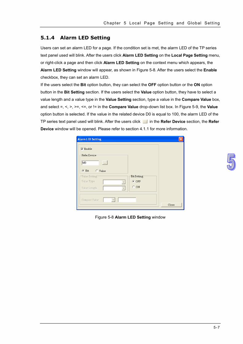
Chapter 5 Local Page Set t ing and Global Set t ing
5-7
5.1.4 Alarm LED Setting
Users can set an alarm LED for a page. If the condition set is met, the alarm LED of the TP series
text panel used will blink. After the users click Alarm LED Setting on the Local Page Setting menu,
or right-click a page and then click Alarm LED Setting on the context menu which appears, the
Alarm LED Setting window will appear, as shown in Figure 5-8. After the users select the Enable
checkbox, they can set an alarm LED.
If the users select the Bit option button, they can select the OFF option button or the ON option
button in the Bit Setting section. If the users select the Value option button, they have to select a
value length and a value type in the Value Setting section, type a value in the Compare Value box,
and select =, <, >, >=, <=, or != in the Compare Value drop-down list box. In Figure 5-9, the Value
option button is selected. If the value in the related device D0 is equal to 100, the alarm LED of the
TP series text panel used will blink. After the users click in the Refer Device section, the Refer
Device window will be opened. Please refer to section 4.1.1 for more information.
Figure 5-8 Alarm LED Setting window
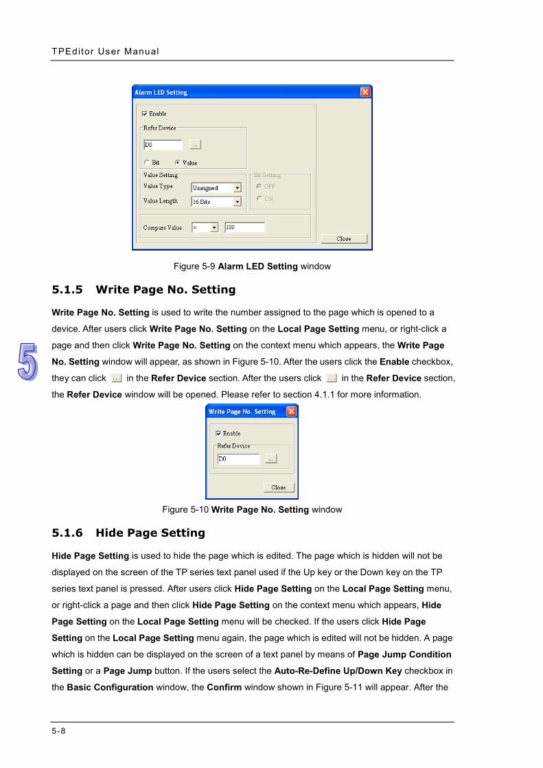
TPEditor User Manual
5-8
Figure 5-9 Alarm LED Setting window
5.1.5 Write Page No. Setting
Write Page No. Setting is used to write the number assigned to the page which is opened to a
device. After users click Write Page No. Setting on the Local Page Setting menu, or right-click a
page and then click Write Page No. Setting on the context menu which appears, the Write Page
No. Setting window will appear, as shown in Figure 5-10. After the users click the Enable checkbox,
they can click in the Refer Device section. After the users click in the Refer Device section,
the Refer Device window will be opened. Please refer to section 4.1.1 for more information.
Figure 5-10 Write Page No. Setting window
5.1.6 Hide Page Setting
Hide Page Setting is used to hide the page which is edited. The page which is hidden will not be
displayed on the screen of the TP series text panel used if the Up key or the Down key on the TP
series text panel is pressed. After users click Hide Page Setting on the Local Page Setting menu,
or right-click a page and then click Hide Page Setting on the context menu which appears, Hide
Page Setting on the Local Page Setting menu will be checked. If the users click Hide Page
Setting on the Local Page Setting menu again, the page which is edited will not be hidden. A page
which is hidden can be displayed on the screen of a text panel by means of Page Jump Condition
Setting or a Page Jump button. If the users select the Auto-Re-Define Up/Down Key checkbox in
the Basic Configuration window, the Confirm window shown in Figure 5-11 will appear. After the
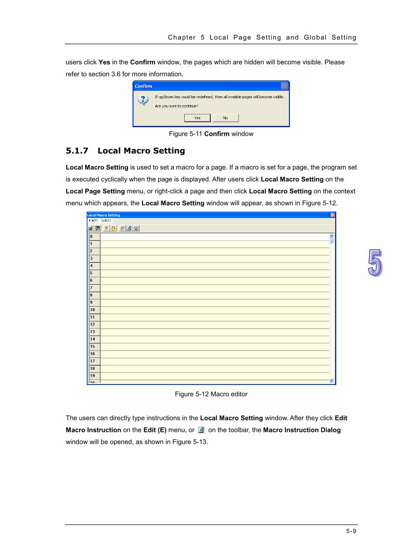
Chapter 5 Local Page Set t ing and Global Set t ing
5-9
users click Yes in the Confirm window, the pages which are hidden will become visible. Please
refer to section 3.6 for more information.
Figure 5-11 Confirm window
5.1.7 Local Macro Setting
Local Macro Setting is used to set a macro for a page. If a macro is set for a page, the program set
is executed cyclically when the page is displayed. After users click Local Macro Setting on the
Local Page Setting menu, or right-click a page and then click Local Macro Setting on the context
menu which appears, the Local Macro Setting window will appear, as shown in Figure 5-12.
Figure 5-12 Macro editor
The users can directly type instructions in the Local Macro Setting window. After they click Edit
Macro Instruction on the Edit (E) menu, or on the toolbar, the Macro Instruction Dialog
window will be opened, as shown in Figure 5-13.
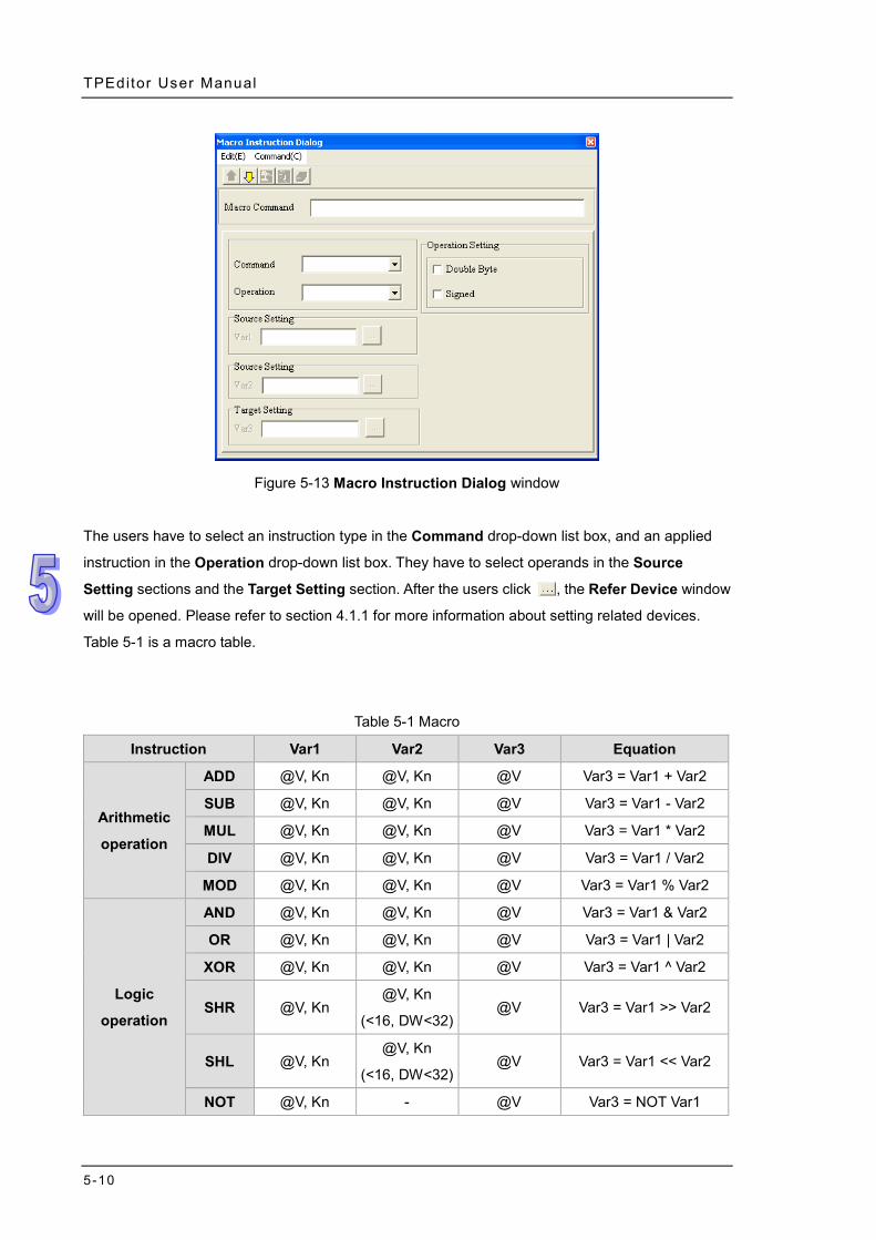
TPEditor User Manual
5-10
Figure 5-13 Macro Instruction Dialog window
The users have to select an instruction type in the Command drop-down list box, and an applied
instruction in the Operation drop-down list box. They have to select operands in the Source
Setting sections and the Target Setting section. After the users click , the Refer Device window
will be opened. Please refer to section 4.1.1 for more information about setting related devices.
Table 5-1 is a macro table.
Table 5-1 Macro
Instruction Var1 Var2 Var3 Equation
Arithmetic
operation
ADD @V, Kn @V, Kn @V Var3 = Var1 + Var2
SUB @V, Kn @V, Kn @V Var3 = Var1 - Var2
MUL @V, Kn @V, Kn @V Var3 = Var1 * Var2
DIV @V, Kn @V, Kn @V Var3 = Var1 / Var2
MOD @V, Kn @V, Kn @V Var3 = Var1 % Var2
Logic
operation
AND @V, Kn @V, Kn @V Var3 = Var1 & Var2
OR @V, Kn @V, Kn @V Var3 = Var1 | Var2
XOR @V, Kn @V, Kn @V Var3 = Var1 ^ Var2
SHR @V, Kn @V, Kn
(<16, DW<32) @V Var3 = Var1 >> Var2
SHL @V, Kn @V, Kn
(<16, DW<32) @V Var3 = Var1 << Var2
NOT @V, Kn - @V Var3 = NOT Var1
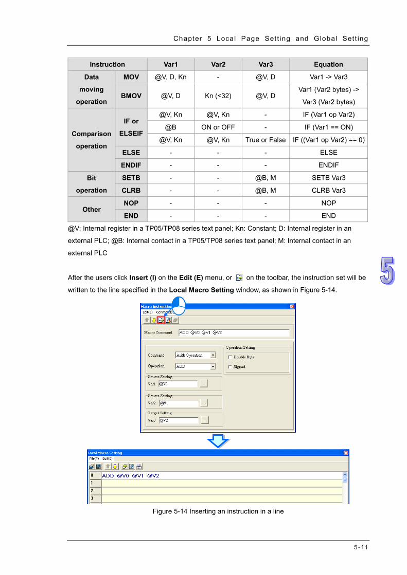
Chapter 5 Local Page Set t ing and Global Set t ing
5-11
Instruction Var1 Var2 Var3 Equation
Data
moving
operation
MOV @V, D, Kn - @V, D Var1 -> Var3
BMOV @V, D Kn (<32) @V, D Var1 (Var2 bytes) ->
Var3 (Var2 bytes)
Comparison
operation
IF or
ELSEIF
@V, Kn @V, Kn - IF (Var1 op Var2)
@B ON or OFF - IF (Var1 == ON)
@V, Kn @V, Kn True or False IF ((Var1 op Var2) == 0)
ELSE - - - ELSE
ENDIF - - - ENDIF
Bit
operation
SETB - - @B, M SETB Var3
CLRB - - @B, M CLRB Var3
Other NOP - - - NOP
END - - - END
@V: Internal register in a TP05/TP08 series text panel; Kn: Constant; D: Internal register in an
external PLC; @B: Internal contact in a TP05/TP08 series text panel; M: Internal contact in an
external PLC
After the users click Insert (I) on the Edit (E) menu, or on the toolbar, the instruction set will be
written to the line specified in the Local Macro Setting window, as shown in Figure 5-14.
Figure 5-14 Inserting an instruction in a line
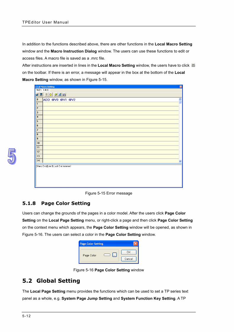
TPEditor User Manual
5-12
In addition to the functions described above, there are other functions in the Local Macro Setting
window and the Macro Instruction Dialog window. The users can use these functions to edit or
access files. A macro file is saved as a .mrc file.
After instructions are inserted in lines in the Local Macro Setting window, the users have to click
on the toolbar. If there is an error, a message will appear in the box at the bottom of the Local
Macro Setting window, as shown in Figure 5-15.
Figure 5-15 Error message
5.1.8 Page Color Setting
Users can change the grounds of the pages in a color model. After the users click Page Color
Setting on the Local Page Setting menu, or right-click a page and then click Page Color Setting
on the context menu which appears, the Page Color Setting window will be opened, as shown in
Figure 5-16. The users can select a color in the Page Color Setting window.
Figure 5-16 Page Color Setting window
5.2 Global Setting
The Local Page Setting menu provides the functions which can be used to set a TP series text
panel as a whole, e.g. System Page Jump Setting and System Function Key Setting. A TP
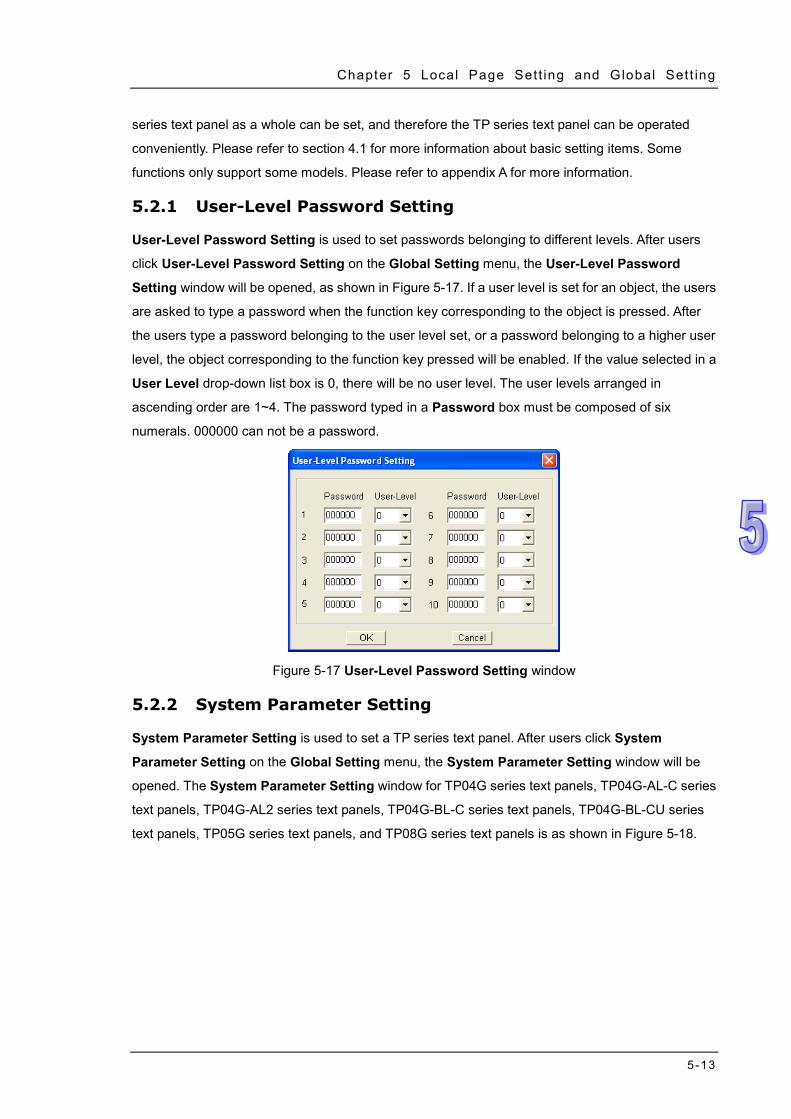
Chapter 5 Local Page Set t ing and Global Set t ing
5-13
series text panel as a whole can be set, and therefore the TP series text panel can be operated
conveniently. Please refer to section 4.1 for more information about basic setting items. Some
functions only support some models. Please refer to appendix A for more information.
5.2.1 User-Level Password Setting
User-Level Password Setting is used to set passwords belonging to different levels. After users
click User-Level Password Setting on the Global Setting menu, the User-Level Password
Setting window will be opened, as shown in Figure 5-17. If a user level is set for an object, the users
are asked to type a password when the function key corresponding to the object is pressed. After
the users type a password belonging to the user level set, or a password belonging to a higher user
level, the object corresponding to the function key pressed will be enabled. If the value selected in a
User Level drop-down list box is 0, there will be no user level. The user levels arranged in
ascending order are 1~4. The password typed in a Password box must be composed of six
numerals. 000000 can not be a password.
Figure 5-17 User-Level Password Setting window
5.2.2 System Parameter Setting
System Parameter Setting is used to set a TP series text panel. After users click System
Parameter Setting on the Global Setting menu, the System Parameter Setting window will be
opened. The System Parameter Setting window for TP04G series text panels, TP04G-AL-C series
text panels, TP04G-AL2 series text panels, TP04G-BL-C series text panels, TP04G-BL-CU series
text panels, TP05G series text panels, and TP08G series text panels is as shown in Figure 5-18.
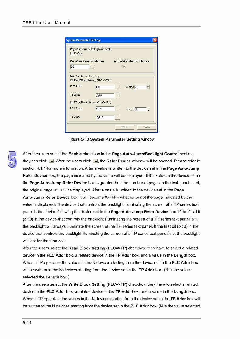
TPEditor User Manual
5-14
Figure 5-18 System Parameter Setting window
After the users select the Enable checkbox in the Page Auto-Jump/Backlight Control section,
they can click . After the users click , the Refer Device window will be opened. Please refer to
section 4.1.1 for more information. After a value is written to the device set in the Page Auto-Jump
Refer Device box, the page indicated by the value will be displayed. If the value in the device set in
the Page Auto-Jump Refer Device box is greater than the number of pages in the text panel used,
the original page will still be displayed. After a value is written to the device set in the Page
Auto-Jump Refer Device box, it will become 0xFFFF whether or not the page indicated by the
value is displayed. The device that controls the backlight illuminating the screen of a TP series text
panel is the device following the device set in the Page Auto-Jump Refer Device box. If the first bit
(bit 0) in the device that controls the backlight illuminating the screen of a TP series text panel is 1,
the backlight will always illuminate the screen of the TP series text panel. If the first bit (bit 0) in the
device that controls the backlight illuminating the screen of a TP series text panel is 0, the backlight
will last for the time set.
After the users select the Read Block Setting (PLC=>TP) checkbox, they have to select a related
device in the PLC Addr box, a related device in the TP Addr box, and a value in the Length box.
When a TP operates, the values in the N devices starting from the device set in the PLC Addr box
will be written to the N devices starting from the device set in the TP Addr box. (N is the value
selected the Length box.)
After the users select the Write Block Setting (PLC=>TP) checkbox, they have to select a related
device in the PLC Addr box, a related device in the TP Addr box, and a value in the Length box.
When a TP operates, the values in the N devices starting from the device set in the TP Addr box will
be written to the N devices starting from the device set in the PLC Addr box. (N is the value selected
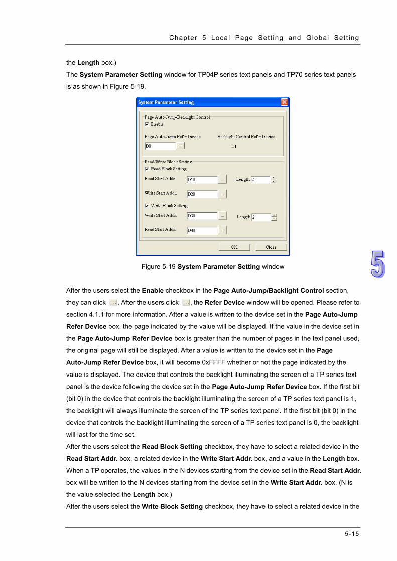
Chapter 5 Local Page Set t ing and Global Set t ing
5-15
the Length box.)
The System Parameter Setting window for TP04P series text panels and TP70 series text panels
is as shown in Figure 5-19.
Figure 5-19 System Parameter Setting window
After the users select the Enable checkbox in the Page Auto-Jump/Backlight Control section,
they can click . After the users click , the Refer Device window will be opened. Please refer to
section 4.1.1 for more information. After a value is written to the device set in the Page Auto-Jump
Refer Device box, the page indicated by the value will be displayed. If the value in the device set in
the Page Auto-Jump Refer Device box is greater than the number of pages in the text panel used,
the original page will still be displayed. After a value is written to the device set in the Page
Auto-Jump Refer Device box, it will become 0xFFFF whether or not the page indicated by the
value is displayed. The device that controls the backlight illuminating the screen of a TP series text
panel is the device following the device set in the Page Auto-Jump Refer Device box. If the first bit
(bit 0) in the device that controls the backlight illuminating the screen of a TP series text panel is 1,
the backlight will always illuminate the screen of the TP series text panel. If the first bit (bit 0) in the
device that controls the backlight illuminating the screen of a TP series text panel is 0, the backlight
will last for the time set.
After the users select the Read Block Setting checkbox, they have to select a related device in the
Read Start Addr. box, a related device in the Write Start Addr. box, and a value in the Length box.
When a TP operates, the values in the N devices starting from the device set in the Read Start Addr.
box will be written to the N devices starting from the device set in the Write Start Addr. box. (N is
the value selected the Length box.)
After the users select the Write Block Setting checkbox, they have to select a related device in the
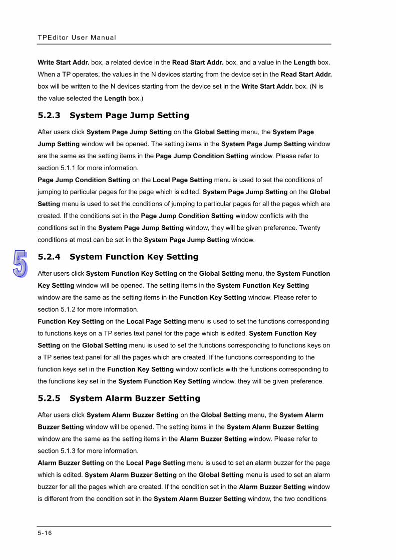
TPEditor User Manual
5-16
Write Start Addr. box, a related device in the Read Start Addr. box, and a value in the Length box.
When a TP operates, the values in the N devices starting from the device set in the Read Start Addr.
box will be written to the N devices starting from the device set in the Write Start Addr. box. (N is
the value selected the Length box.)
5.2.3 System Page Jump Setting
After users click System Page Jump Setting on the Global Setting menu, the System Page
Jump Setting window will be opened. The setting items in the System Page Jump Setting window
are the same as the setting items in the Page Jump Condition Setting window. Please refer to
section 5.1.1 for more information.
Page Jump Condition Setting on the Local Page Setting menu is used to set the conditions of
jumping to particular pages for the page which is edited. System Page Jump Setting on the Global
Setting menu is used to set the conditions of jumping to particular pages for all the pages which are
created. If the conditions set in the Page Jump Condition Setting window conflicts with the
conditions set in the System Page Jump Setting window, they will be given preference. Twenty
conditions at most can be set in the System Page Jump Setting window.
5.2.4 System Function Key Setting
After users click System Function Key Setting on the Global Setting menu, the System Function
Key Setting window will be opened. The setting items in the System Function Key Setting
window are the same as the setting items in the Function Key Setting window. Please refer to
section 5.1.2 for more information.
Function Key Setting on the Local Page Setting menu is used to set the functions corresponding
to functions keys on a TP series text panel for the page which is edited. System Function Key
Setting on the Global Setting menu is used to set the functions corresponding to functions keys on
a TP series text panel for all the pages which are created. If the functions corresponding to the
function keys set in the Function Key Setting window conflicts with the functions corresponding to
the functions key set in the System Function Key Setting window, they will be given preference.
5.2.5 System Alarm Buzzer Setting
After users click System Alarm Buzzer Setting on the Global Setting menu, the System Alarm
Buzzer Setting window will be opened. The setting items in the System Alarm Buzzer Setting
window are the same as the setting items in the Alarm Buzzer Setting window. Please refer to
section 5.1.3 for more information.
Alarm Buzzer Setting on the Local Page Setting menu is used to set an alarm buzzer for the page
which is edited. System Alarm Buzzer Setting on the Global Setting menu is used to set an alarm
buzzer for all the pages which are created. If the condition set in the Alarm Buzzer Setting window
is different from the condition set in the System Alarm Buzzer Setting window, the two conditions
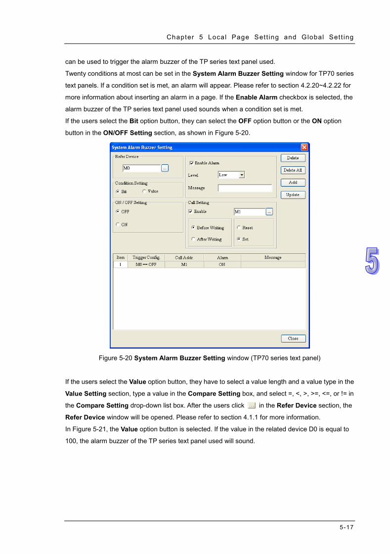
Chapter 5 Local Page Set t ing and Global Set t ing
5-17
can be used to trigger the alarm buzzer of the TP series text panel used.
Twenty conditions at most can be set in the System Alarm Buzzer Setting window for TP70 series
text panels. If a condition set is met, an alarm will appear. Please refer to section 4.2.20~4.2.22 for
more information about inserting an alarm in a page. If the Enable Alarm checkbox is selected, the
alarm buzzer of the TP series text panel used sounds when a condition set is met.
If the users select the Bit option button, they can select the OFF option button or the ON option
button in the ON/OFF Setting section, as shown in Figure 5-20.
Figure 5-20 System Alarm Buzzer Setting window (TP70 series text panel)
If the users select the Value option button, they have to select a value length and a value type in the
Value Setting section, type a value in the Compare Setting box, and select =, <, >, >=, <=, or != in
the Compare Setting drop-down list box. After the users click in the Refer Device section, the
Refer Device window will be opened. Please refer to section 4.1.1 for more information.
In Figure 5-21, the Value option button is selected. If the value in the related device D0 is equal to
100, the alarm buzzer of the TP series text panel used will sound.
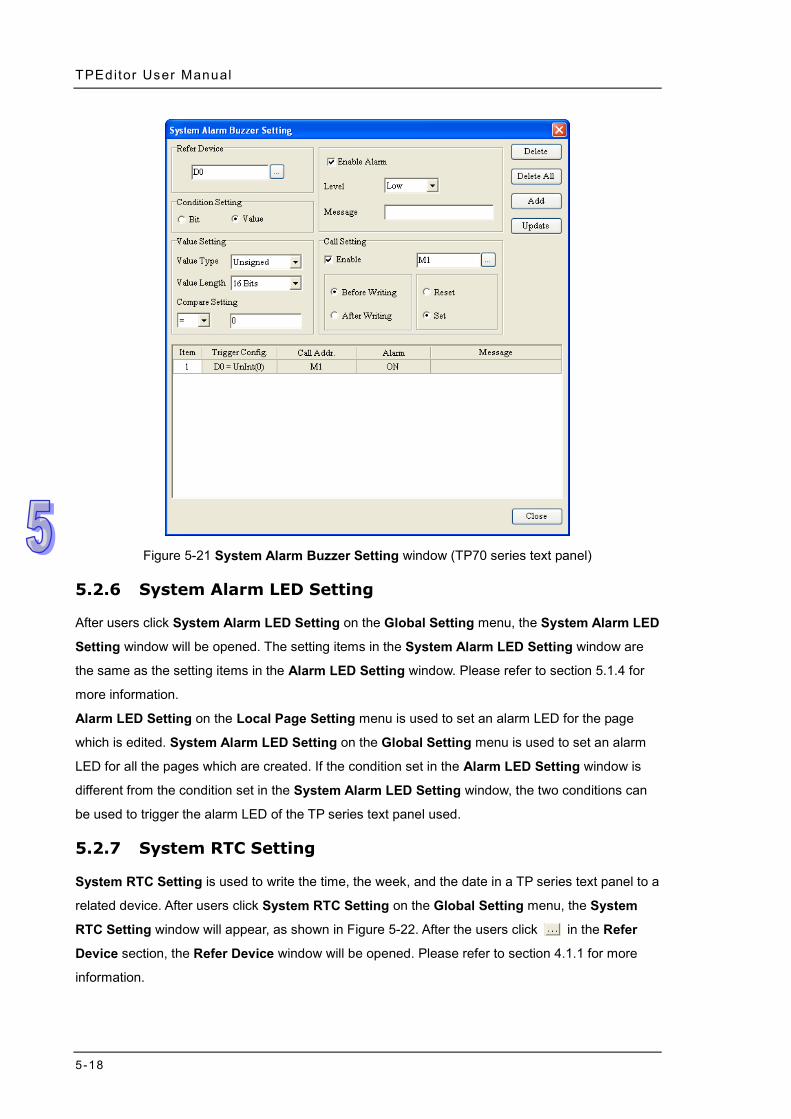
TPEditor User Manual
5-18
Figure 5-21 System Alarm Buzzer Setting window (TP70 series text panel)
5.2.6 System Alarm LED Setting
After users click System Alarm LED Setting on the Global Setting menu, the System Alarm LED
Setting window will be opened. The setting items in the System Alarm LED Setting window are
the same as the setting items in the Alarm LED Setting window. Please refer to section 5.1.4 for
more information.
Alarm LED Setting on the Local Page Setting menu is used to set an alarm LED for the page
which is edited. System Alarm LED Setting on the Global Setting menu is used to set an alarm
LED for all the pages which are created. If the condition set in the Alarm LED Setting window is
different from the condition set in the System Alarm LED Setting window, the two conditions can
be used to trigger the alarm LED of the TP series text panel used.
5.2.7 System RTC Setting
System RTC Setting is used to write the time, the week, and the date in a TP series text panel to a
related device. After users click System RTC Setting on the Global Setting menu, the System
RTC Setting window will appear, as shown in Figure 5-22. After the users click in the Refer
Device section, the Refer Device window will be opened. Please refer to section 4.1.1 for more
information.
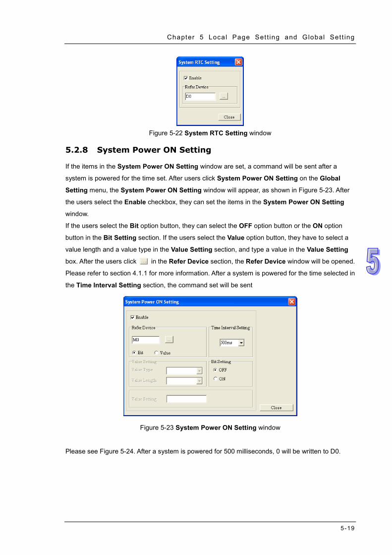
Chapter 5 Local Page Set t ing and Global Set t ing
5-19
Figure 5-22 System RTC Setting window
5.2.8 System Power ON Setting
If the items in the System Power ON Setting window are set, a command will be sent after a
system is powered for the time set. After users click System Power ON Setting on the Global
Setting menu, the System Power ON Setting window will appear, as shown in Figure 5-23. After
the users select the Enable checkbox, they can set the items in the System Power ON Setting
window.
If the users select the Bit option button, they can select the OFF option button or the ON option
button in the Bit Setting section. If the users select the Value option button, they have to select a
value length and a value type in the Value Setting section, and type a value in the Value Setting
box. After the users click in the Refer Device section, the Refer Device window will be opened.
Please refer to section 4.1.1 for more information. After a system is powered for the time selected in
the Time Interval Setting section, the command set will be sent
Figure 5-23 System Power ON Setting window
Please see Figure 5-24. After a system is powered for 500 milliseconds, 0 will be written to D0.
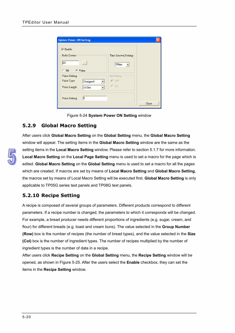
TPEditor User Manual
5-20
Figure 5-24 System Power ON Setting window
5.2.9 Global Macro Setting
After users click Global Macro Setting on the Global Setting menu, the Global Macro Setting
window will appear. The setting items in the Global Macro Setting window are the same as the
setting items in the Local Macro Setting window. Please refer to section 5.1.7 for more information.
Local Macro Setting on the Local Page Setting menu is used to set a macro for the page which is
edited. Global Macro Setting on the Global Setting menu is used to set a macro for all the pages
which are created. If macros are set by means of Local Macro Setting and Global Macro Setting,
the macros set by means of Local Macro Setting will be executed first. Global Macro Setting is only
applicable to TP05G series text panels and TP08G text panels.
5.2.10 Recipe Setting
A recipe is composed of several groups of parameters. Different products correspond to different
parameters. If a recipe number is changed, the parameters to which it corresponds will be changed.
For example, a bread producer needs different proportions of ingredients (e.g. sugar, cream, and
flour) for different breads (e.g. toast and cream buns). The value selected in the Group Number
(Row) box is the number of recipes (the number of bread types), and the value selected in the Size
(Col) box is the number of ingredient types. The number of recipes multiplied by the number of
ingredient types is the number of data in a recipe.
After users click Recipe Setting on the Global Setting menu, the Recipe Setting window will be
opened, as shown in Figure 5-25. After the users select the Enable checkbox, they can set the
items in the Recipe Setting window.
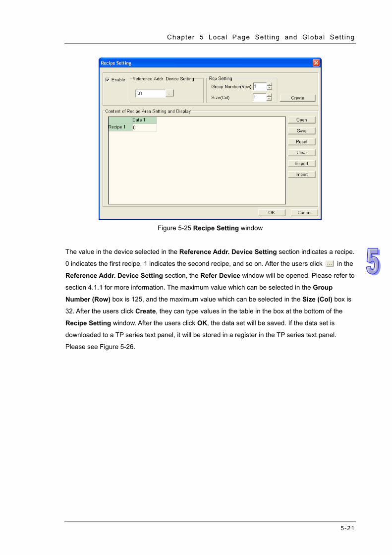
Chapter 5 Local Page Set t ing and Global Set t ing
5-21
Figure 5-25 Recipe Setting window
The value in the device selected in the Reference Addr. Device Setting section indicates a recipe.
0 indicates the first recipe, 1 indicates the second recipe, and so on. After the users click in the
Reference Addr. Device Setting section, the Refer Device window will be opened. Please refer to
section 4.1.1 for more information. The maximum value which can be selected in the Group
Number (Row) box is 125, and the maximum value which can be selected in the Size (Col) box is
32. After the users click Create, they can type values in the table in the box at the bottom of the
Recipe Setting window. After the users click OK, the data set will be saved. If the data set is
downloaded to a TP series text panel, it will be stored in a register in the TP series text panel.
Please see Figure 5-26.
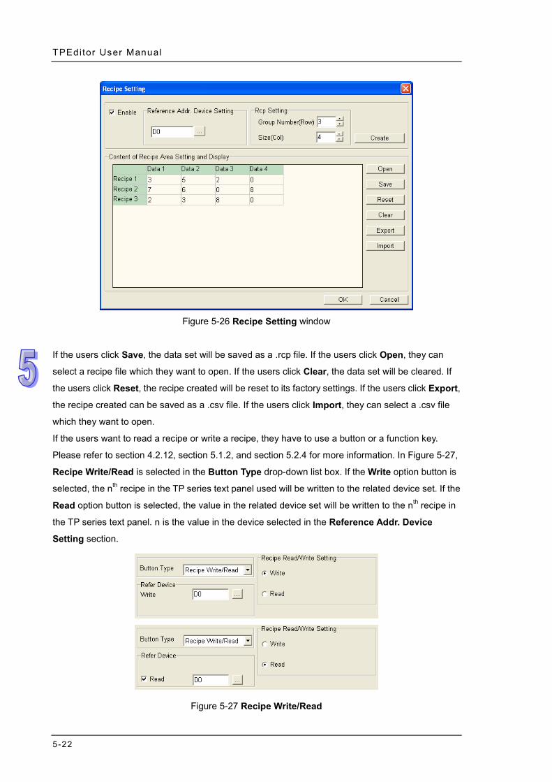
TPEditor User Manual
5-22
Figure 5-26 Recipe Setting window
If the users click Save, the data set will be saved as a .rcp file. If the users click Open, they can
select a recipe file which they want to open. If the users click Clear, the data set will be cleared. If
the users click Reset, the recipe created will be reset to its factory settings. If the users click Export,
the recipe created can be saved as a .csv file. If the users click Import, they can select a .csv file
which they want to open.
If the users want to read a recipe or write a recipe, they have to use a button or a function key.
Please refer to section 4.2.12, section 5.1.2, and section 5.2.4 for more information. In Figure 5-27,
Recipe Write/Read is selected in the Button Type drop-down list box. If the Write option button is
selected, the nth recipe in the TP series text panel used will be written to the related device set. If the
Read option button is selected, the value in the related device set will be written to the nth recipe in
the TP series text panel. n is the value in the device selected in the Reference Addr. Device
Setting section.
Figure 5-27 Recipe Write/Read
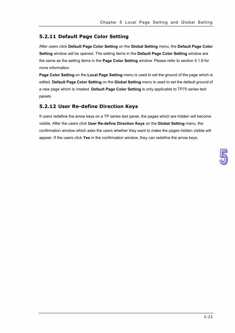
Chapter 5 Local Page Set t ing and Global Set t ing
5-23
5.2.11 Default Page Color Setting
After users click Default Page Color Setting on the Global Setting menu, the Default Page Color
Setting window will be opened. The setting items in the Default Page Color Setting window are
the same as the setting items in the Page Color Setting window. Please refer to section 5.1.8 for
more information.
Page Color Setting on the Local Page Setting menu is used to set the ground of the page which is
edited. Default Page Color Setting on the Global Setting menu is used to set the default ground of
a new page which is created. Default Page Color Setting is only applicable to TP70 series text
panels.
5.2.12 User Re-define Direction Keys
If users redefine the arrow keys on a TP series text panel, the pages which are hidden will become
visible. After the users click User Re-define Direction Keys on the Global Setting menu, the
confirmation window which asks the users whether they want to make the pages hidden visible will
appear. If the users click Yes in the confirmation window, they can redefine the arrow keys.

TPEditor User Manual
5-24
MEMO
6-1
Chapter 6 Connection and Examples Contents 6.1 Connection and Uploading/Downloading a Project .................................. 6-2
6.1.1 Setting a Connection ......................................................................... 6-2 6.1.2 Downloading/Uploading a Project ..................................................... 6-3
6.2 Examples .................................................................................................. 6-5 6.2.1 Example 1: Designing and Using a Boot Page .................................. 6-5 6.2.2 Example 2: Connecting a TP Series Text Panel to a Delta PLC ........ 6-9
TPEditor User Manual
6-2
6.1 Connection and Uploading/Downloading a Project
After users edit a project in ways described in the previous chapters, they can download the project
to a TP series text panel. If the users want to modify the data in a TP series text panel, they can
upload the data to a computer. The steps of connecting a TP04G series text panel, the steps of
downloading a project to a TP04G series text panel, and the steps of uploading the data in a TP04G
series text panel are described in the following sections.
6.1.1 Setting a Connection
After the users press Esc on a TP04G series text panel for a long time, menus will be displayed on
the screen of the TP04G series text panel. After the users select TP04G SETUP and COM PORT by
means of Up/Pg UP, Down/Pg Dn, and Enter on the TP04G series text panel, three items will be
displayed, as shown in Figure 6-1.
TP04 PROTOCOL: It is used to set the communication address of the TP series text panel.
RS232: It is used to set a data transmission speed, a data length, a parity bit, and the number of
stop bits.
RS485: It is used to set a data transmission speed, a data length, a parity bit, and the number of
stop bits.
Figure 6-1 Screen of a TP series text panel
After the users click Basic Configuration on the Tool menu in TPEditor, they have to click
PC<=>TP Communication Setting in the Basic Configuration window. In the PC
Communication Setting (PC<=>TP) section, the users have to select a station address in the TP
COM PORT
1. TP04 PROTOCOL 2. RS232 3. RS485
Chapter 6 Connect ion and Examples
6-3
Station Address box, a communication port in the PC COM Port box, and a data transmission
speed in the Baud Rate drop-down list box, as shown in Figure 6-2. The station address selected in
the TP Station Address box must be the same as the station address set in the TP04G series text
panel.
Figure 6-2 Setting communication in a computer
The users have to click TP<=>PLC Protocol in the Basic Configuration window, and set the
communication port which is connected to equipment. They have to select a data transmission
speed in the Baud Rate drop-down list box, a data length in the Data Length drop-down list box, a
parity bit in the Parity drop-down list box, and the number of stop bits in the Stop Bit drop-down list
box, as shown in Figure 6-3. After the settings are downloaded to the TP04G series text panel, they
will overwrite the settings on menus in the TP04G series text panel.
Figure 6-3 Setting communication in a TP series text panel
After the users connect the computer used to the TP04G series text panel according to the
instructions in TP04G Instruction Sheet, they can download a project to the TP04G series text panel,
and upload the project in the TP04G series text panel. If the users want to connect a TP70 series
text panel to TPEditor, they do not need to set the TP70 series text panel, and only need to set
TPEditor.
6.1.2 Downloading/Uploading a Project
After users connect a computer to a TP02G series text panel, a TP04G series text panel,
TP04G-AL-C series text panel, a TP04G-AL2 series text panel, a TP05G series text panel, a TP08G
series text panel, or a VFD-C series keypad according to the instructions in the previous section,
they have to touch 1. D/L AP TP model type PC on the screen of the text panel if they want to
download data to the text panel. After 1. D/L AP TP model type PC on the screen of the text
panel used is touched, “WAIT COMM…” will be displayed on the screen of the text panel used, as
TPEditor User Manual
6-4
shown in Figure 6-4.
Figure 6-4 WAIT COMM…
After the users click Write to TP on the Communication menu or on the standard toolbar, the
Confirm window will appear. After the users click Yes in the Confirm window, the window showing
the percentage of progress in downloading the project created will appear, as shown in Figure 6-5.
Figure 6-5 Downloading a project
After the users click Yes in the Confirm window, the progress bar showing the percentage of
progress in downloading the project created will be displayed on the text panel used, as shown in
Figure 6-6.
Figure 6-6 RECEIVING…
After the project created is downloaded, a message will appear in TPEditor, and a message will be
displayed on the screen of the text panel used, as shown in Figure 6-7.
RECEIVING…
29%
WAIT COMM…
Chapter 6 Connect ion and Examples
6-5
Figure 6-7 Transmission finished
If the users want to upload the data in a TP series text panel to a computer, they have to click Read
from TP on the Communication menu or on the standard toolbar, and touch 2. U/L AP model
type PC on the screen of the TP series text panel. If the users want to download the boot page
or the user menus in TPEditor to a TP series text panel, they have to follow the instructions in
section 3.5. If the users want to download a project to a TP70 series text panel, or upload the data in
a TP70 series text panel to a computer, they do not need to set the TP70 series text panel, and only
need to click Write to TP or Read from TP in TPEditor. Besides, the general pages and the boot
page designed in TPEditor can be downloaded to a TP70 series text panel simultaneously.
6.2 Examples
Two examples of operating a TP series text panel are provided in section 6.2.1 and section 6.2.2.
Before users download a project, they have to set a connection. Please refer to section 6.1.1 for
more information. TP04G series text panels are used in the two examples.
6.2.1 Example 1: Designing and Using a Boot Page
Description: A boot page is designed. After the boot page is downloaded to a TP series text pane,
the boot page displayed on the screen of the TP series text panel will be the boot page designed.
Step 1: Start TPEditor. Click New on the File menu, or on the standard toolbar. After users
select a model, and click OK in the New Project window, a blank project will be created. After
the users click Boot Page on the View menu, or Boot Page in the page management area, the
Boot Page window will appear, as shown in Figure 6-8.
RECEIVING…
FINISHED!
ESC:EXIT
TPEditor User Manual
6-6
Figure 6-8 Boot Page window
Step 2: Only geometric object, static text, and static images can be inserted in the Boot Page
window. After the users click Static Bitmap on the object toolbar, they can click where they want
to begin the selection of an area in the Boot Page window, hold down the left mouse button,
and drag the cross over the area that they want to select. The object will be inserted into
the area selected after the users release the left mouse button, as shown in Figure 6-9.
Figure 6-9 Inserting a static image
Chapter 6 Connect ion and Examples
6-7
Step 3: After the users double-click in the Boot Page window, the Open window will
appear. The users have to select a .bmp file in the Open window. After the users click Open in
the Open window, an image will be inserted in the Boot Page window, as shown in Figure 6-10.
Figure 6-10 Selecting a static image
Step 4: After the users finish editing a boot page, they can download the boot page. After the
users press Esc on the TP04G series text panel used for a long time, menus will be displayed
on the screen of the TP04G series text panel. After 1. D/L AP TP04G PC on the screen of
the TP04G series text panel is touched, “WAIT COMM…” will be displayed on the screen of the
TP04G series text panel, as shown in Figure 6-11.
TPEditor User Manual
6-8
Figure 6-11 Touching 1. D/L AP TP04G PC
Step 5: After the users click Write Boot Page to TP on the Communication menu, the boot
page edited will be downloaded to the TP04G series text panel, and the window showing the
percentage of progress in downloading the boot page will appear, as shown in Figure 6-12 The
boot page edited does not need to be compiled before it is downloaded.
Figure 6-12 Downloading a boot page
Step 6: The users have to touch 4.TP04G SETUP, touch 8. START-UP DISPLAY, and touch 2.
USER DEFINE on the screen of the TP04G series text panel in order, as shown in Figure 6-13.
After they set the TP04G series text panel, the boot page displayed on the TP04G series text
WAIT COMM….
1.D/L AP TP04G PC 2.U/L AP TP04G PC 3.Copy AP TP04G TP04G 4.TP04G SETUP
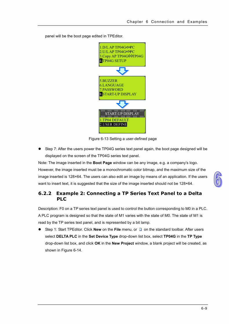
Chapter 6 Connect ion and Examples
6-9
panel will be the boot page edited in TPEditor.
Figure 6-13 Setting a user-defined page
Step 7: After the users power the TP04G series text panel again, the boot page designed will be
displayed on the screen of the TP04G series text panel.
Note: The image inserted in the Boot Page window can be any image, e.g. a company’s logo.
However, the image inserted must be a monochromatic color bitmap, and the maximum size of the
image inserted is 128×64. The users can also edit an image by means of an application. If the users
want to insert text, it is suggested that the size of the image inserted should not be 128×64.
6.2.2 Example 2: Connecting a TP Series Text Panel to a Delta PLC
Description: F0 on a TP series text panel is used to control the button corresponding to M0 in a PLC.
A PLC program is designed so that the state of M1 varies with the state of M0. The state of M1 is
read by the TP series text panel, and is represented by a bit lamp.
Step 1: Start TPEditor. Click New on the File menu, or on the standard toolbar. After users
select DELTA PLC in the Set Device Type drop-down list box, select TP04G in the TP Type
drop-down list box, and click OK in the New Project window, a blank project will be created, as
shown in Figure 6-14.
5.BUZZER 6.LANGUAGE 7.PASSWORD 8.START-UP DISPLAY
1.TP04 DEFAULT 2.USER DEFINE
START-UP DISPLAY
1.D/L AP TP04G PC 2.U/L AP TP04G PC 3.Copy AP TP04G TP04G 4.TP04G SETUP
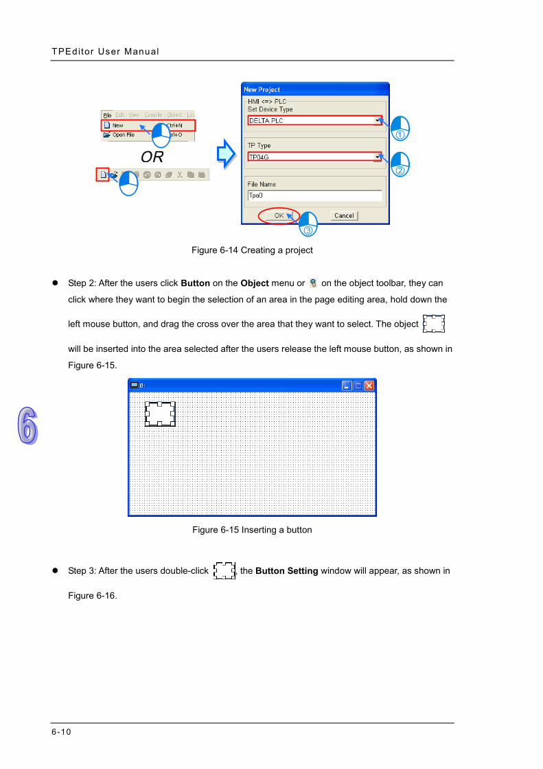
TPEditor User Manual
6-10
Figure 6-14 Creating a project
Step 2: After the users click Button on the Object menu or on the object toolbar, they can
click where they want to begin the selection of an area in the page editing area, hold down the
left mouse button, and drag the cross over the area that they want to select. The object
will be inserted into the area selected after the users release the left mouse button, as shown in
Figure 6-15.
Figure 6-15 Inserting a button
Step 3: After the users double-click , the Button Setting window will appear, as shown in
Figure 6-16.
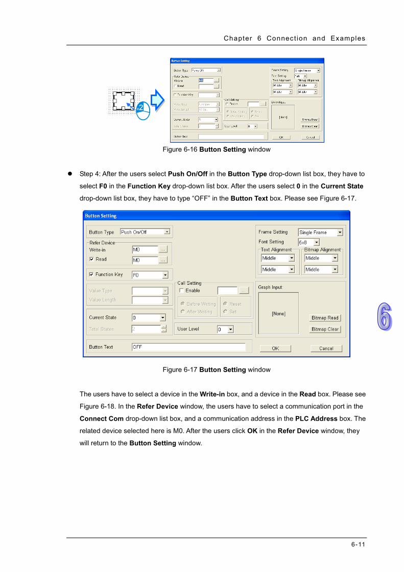
Chapter 6 Connect ion and Examples
6-11
Figure 6-16 Button Setting window
Step 4: After the users select Push On/Off in the Button Type drop-down list box, they have to
select F0 in the Function Key drop-down list box. After the users select 0 in the Current State
drop-down list box, they have to type “OFF” in the Button Text box. Please see Figure 6-17.
Figure 6-17 Button Setting window
The users have to select a device in the Write-in box, and a device in the Read box. Please see
Figure 6-18. In the Refer Device window, the users have to select a communication port in the
Connect Com drop-down list box, and a communication address in the PLC Address box. The
related device selected here is M0. After the users click OK in the Refer Device window, they
will return to the Button Setting window.
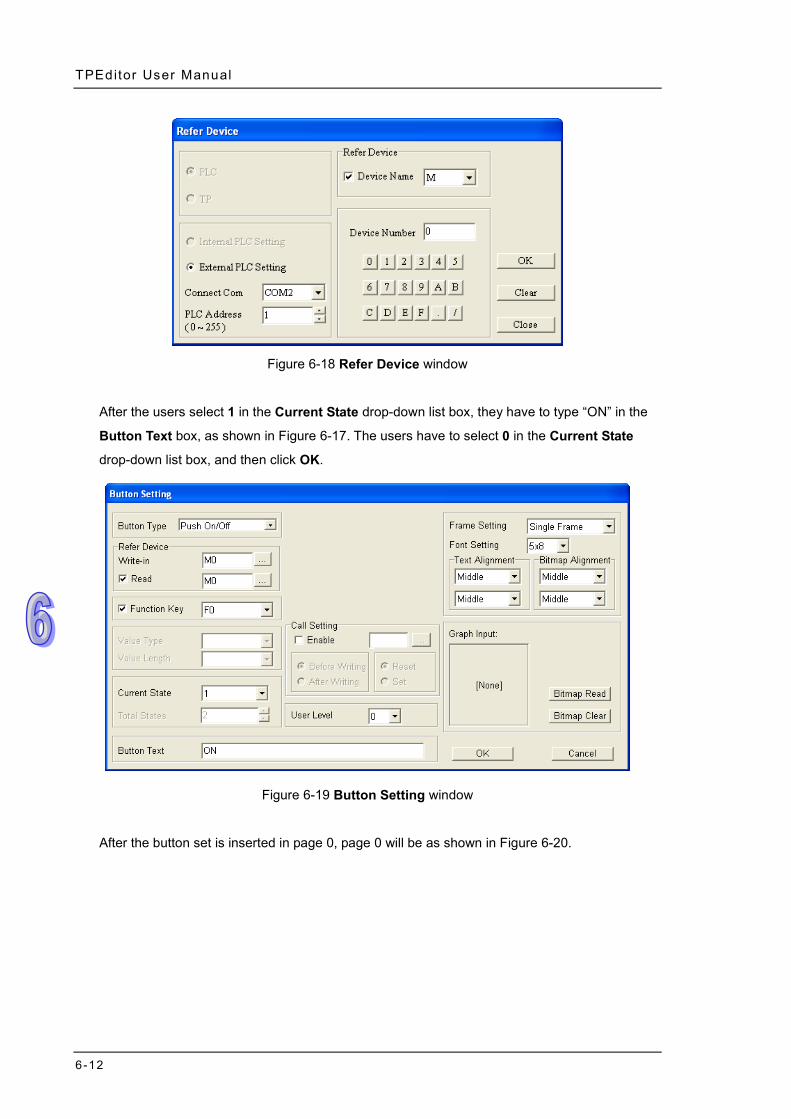
TPEditor User Manual
6-12
Figure 6-18 Refer Device window
After the users select 1 in the Current State drop-down list box, they have to type “ON” in the
Button Text box, as shown in Figure 6-17. The users have to select 0 in the Current State
drop-down list box, and then click OK.
Figure 6-19 Button Setting window
After the button set is inserted in page 0, page 0 will be as shown in Figure 6-20.
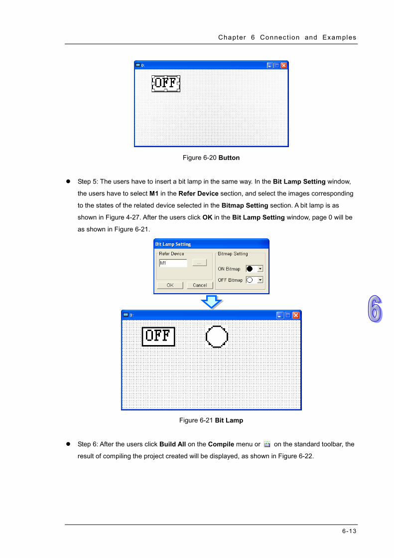
Chapter 6 Connect ion and Examples
6-13
Figure 6-20 Button
Step 5: The users have to insert a bit lamp in the same way. In the Bit Lamp Setting window,
the users have to select M1 in the Refer Device section, and select the images corresponding
to the states of the related device selected in the Bitmap Setting section. A bit lamp is as
shown in Figure 4-27. After the users click OK in the Bit Lamp Setting window, page 0 will be
as shown in Figure 6-21.
Figure 6-21 Bit Lamp
Step 6: After the users click Build All on the Compile menu or on the standard toolbar, the
result of compiling the project created will be displayed, as shown in Figure 6-22.
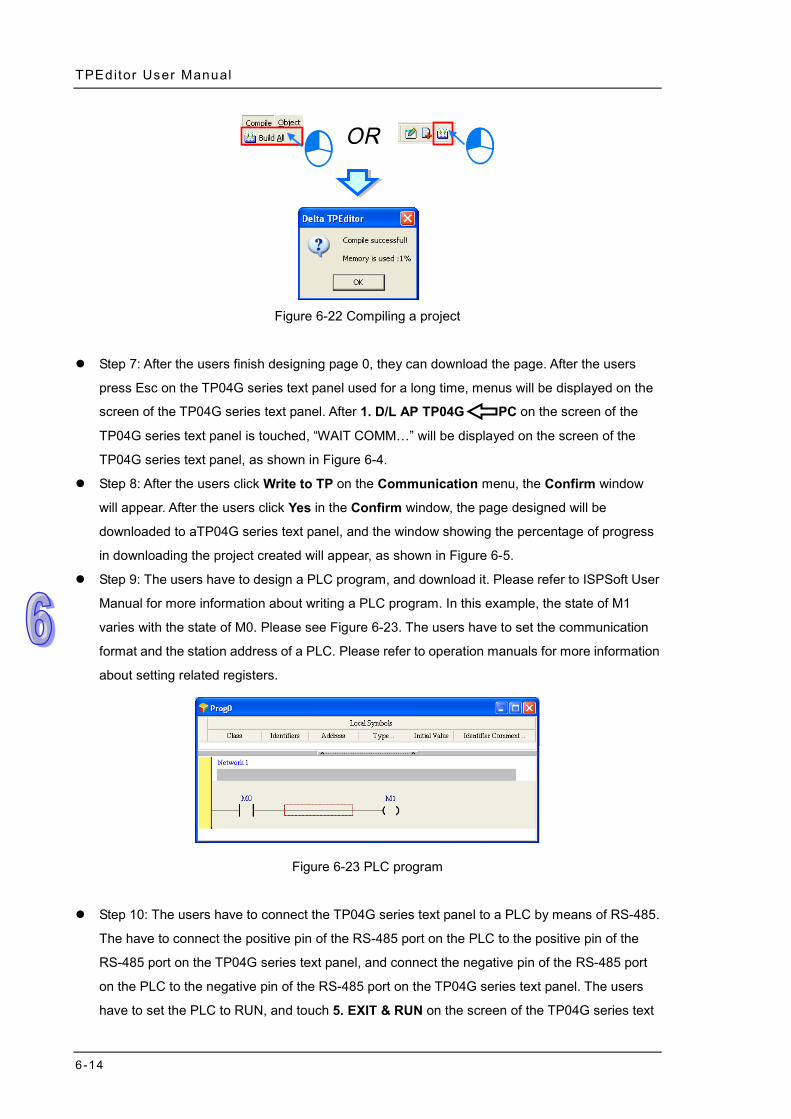
TPEditor User Manual
6-14
Figure 6-22 Compiling a project
Step 7: After the users finish designing page 0, they can download the page. After the users
press Esc on the TP04G series text panel used for a long time, menus will be displayed on the
screen of the TP04G series text panel. After 1. D/L AP TP04G PC on the screen of the
TP04G series text panel is touched, “WAIT COMM…” will be displayed on the screen of the
TP04G series text panel, as shown in Figure 6-4.
Step 8: After the users click Write to TP on the Communication menu, the Confirm window
will appear. After the users click Yes in the Confirm window, the page designed will be
downloaded to aTP04G series text panel, and the window showing the percentage of progress
in downloading the project created will appear, as shown in Figure 6-5.
Step 9: The users have to design a PLC program, and download it. Please refer to ISPSoft User
Manual for more information about writing a PLC program. In this example, the state of M1
varies with the state of M0. Please see Figure 6-23. The users have to set the communication
format and the station address of a PLC. Please refer to operation manuals for more information
about setting related registers.
Figure 6-23 PLC program
Step 10: The users have to connect the TP04G series text panel to a PLC by means of RS-485.
The have to connect the positive pin of the RS-485 port on the PLC to the positive pin of the
RS-485 port on the TP04G series text panel, and connect the negative pin of the RS-485 port
on the PLC to the negative pin of the RS-485 port on the TP04G series text panel. The users
have to set the PLC to RUN, and touch 5. EXIT & RUN on the screen of the TP04G series text
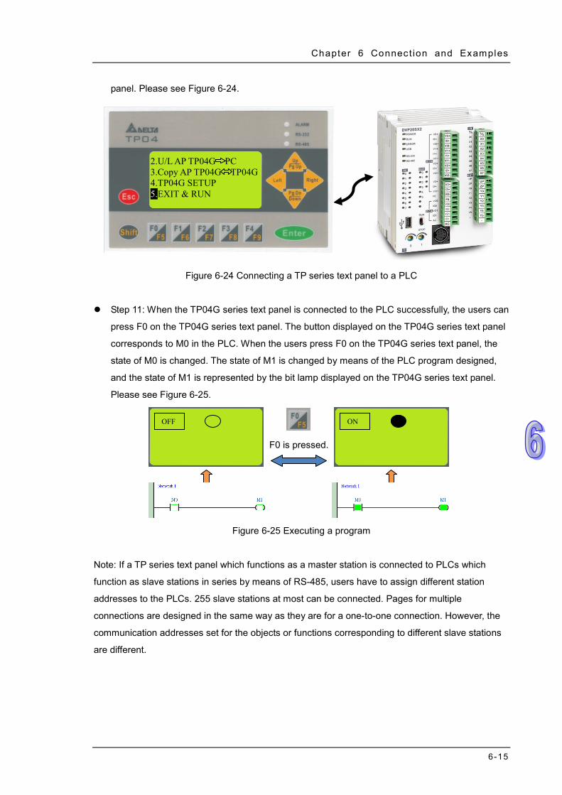
Chapter 6 Connect ion and Examples
6-15
panel. Please see Figure 6-24.
Figure 6-24 Connecting a TP series text panel to a PLC
Step 11: When the TP04G series text panel is connected to the PLC successfully, the users can
press F0 on the TP04G series text panel. The button displayed on the TP04G series text panel
corresponds to M0 in the PLC. When the users press F0 on the TP04G series text panel, the
state of M0 is changed. The state of M1 is changed by means of the PLC program designed,
and the state of M1 is represented by the bit lamp displayed on the TP04G series text panel.
Please see Figure 6-25.
Figure 6-25 Executing a program
Note: If a TP series text panel which functions as a master station is connected to PLCs which
function as slave stations in series by means of RS-485, users have to assign different station
addresses to the PLCs. 255 slave stations at most can be connected. Pages for multiple
connections are designed in the same way as they are for a one-to-one connection. However, the
communication addresses set for the objects or functions corresponding to different slave stations
are different.
OFF
F0 is pressed.
ON
2.U/L AP TP04G PC 3.Copy AP TP04G TP04G 4.TP04G SETUP 5.EXIT & RUN

TPEditor User Manual
6-16
MEMO

A-1
Appendix A Functions Supported by Models Contents A.1 Objects Supported by Models .................................................................. A-2 A.2 Button Types Supported by Models ......................................................... A-3 A.3 Items Supported by Models on the Local Page Setting Menu .................. A-4 A.4 Items Supported by Models on the Global Setting Menu.......................... A-5
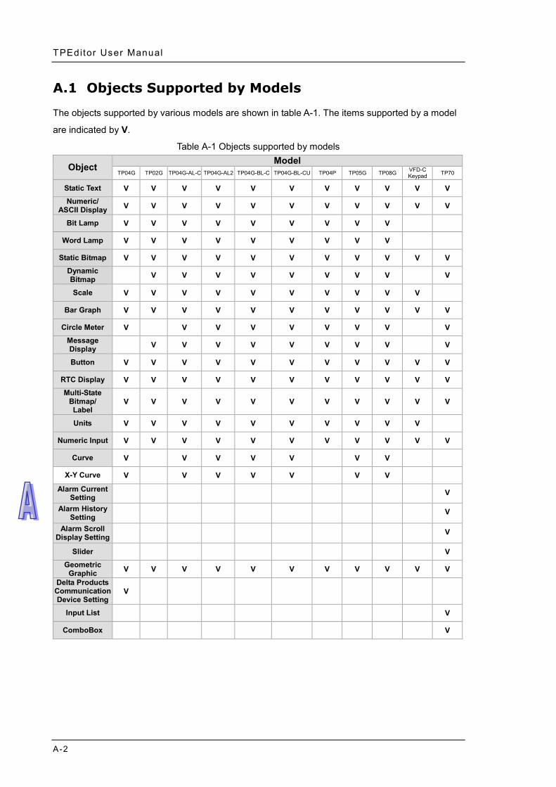
TPEditor User Manual
A-2
A.1 Objects Supported by Models
The objects supported by various models are shown in table A-1. The items supported by a model
are indicated by V.
Table A-1 Objects supported by models
Object Model
TP04G TP02G TP04G-AL-C TP04G-AL2 TP04G-BL-C TP04G-BL-CU TP04P TP05G TP08G VFD-C Keypad TP70
Static Text V V V V V V V V V V V Numeric/
ASCII Display V V V V V V V V V V V Bit Lamp V V V V V V V V V
Word Lamp V V V V V V V V V Static Bitmap V V V V V V V V V V V
Dynamic Bitmap V V V V V V V V V Scale V V V V V V V V V V
Bar Graph V V V V V V V V V V V Circle Meter V V V V V V V V V
Message Display V V V V V V V V V Button V V V V V V V V V V V
RTC Display V V V V V V V V V V V Multi-State
Bitmap/ Label
V V V V V V V V V V V
Units V V V V V V V V V V Numeric Input V V V V V V V V V V V
Curve V V V V V V V X-Y Curve V V V V V V V
Alarm Current Setting V
Alarm History Setting V
Alarm Scroll Display Setting V
Slider V Geometric
Graphic V V V V V V V V V V V Delta Products Communication Device Setting
V
Input List V
ComboBox V
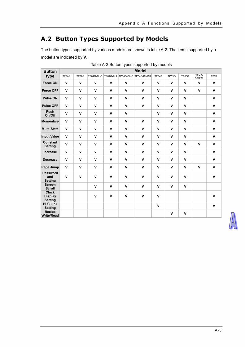
Appendix A Funct ions Suppor ted by Models
A-3
A.2 Button Types Supported by Models
The button types supported by various models are shown in table A-2. The items supported by a
model are indicated by V.
Table A-2 Button types supported by models Button
type Model
TP04G TP02G TP04G-AL-C TP04G-AL2 TP04G-BL-C TP04G-BL-CU TP04P TP05G TP08G VFD-C Keypad TP70
Force ON V V V V V V V V V V V Force OFF V V V V V V V V V V V Pulse ON V V V V V V V V V V Pulse OFF V V V V V V V V V V
Push On/Off V V V V V V V V V
Momentary V V V V V V V V V V Multi-State V V V V V V V V V V Input Value V V V V V V V V V V Constant Setting V V V V V V V V V V V
Increase V V V V V V V V V V Decrease V V V V V V V V V V
Page Jump V V V V V V V V V V V Password
and Setting
V V V V V V V V V V Screen Scroll V V V V V V V Clock
Display Setting
V V V V V V PLC Link Setting V V Recipe
Write/Read V V
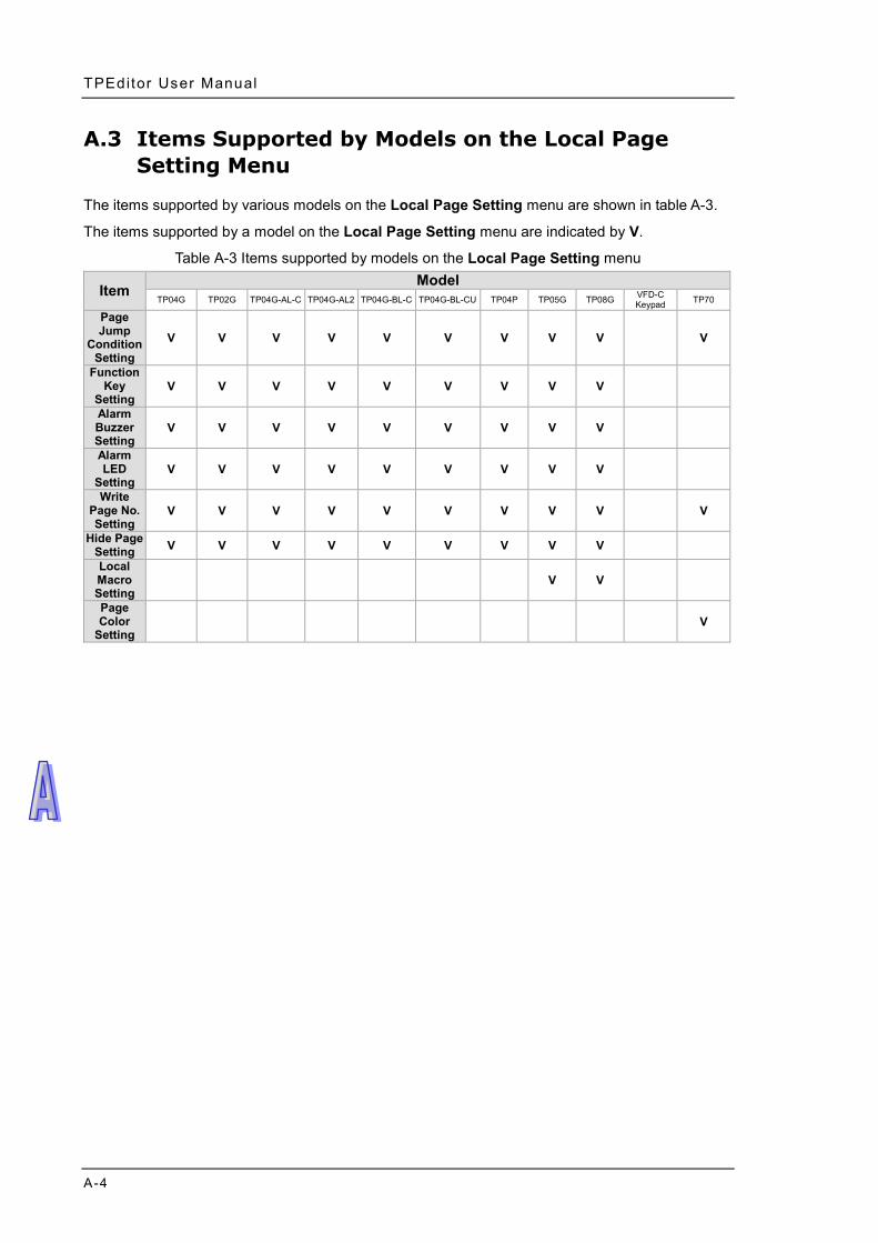
TPEditor User Manual
A-4
A.3 Items Supported by Models on the Local Page Setting Menu
The items supported by various models on the Local Page Setting menu are shown in table A-3.
The items supported by a model on the Local Page Setting menu are indicated by V.
Table A-3 Items supported by models on the Local Page Setting menu
Item Model
TP04G TP02G TP04G-AL-C TP04G-AL2 TP04G-BL-C TP04G-BL-CU TP04P TP05G TP08G VFD-C Keypad TP70
Page Jump
Condition Setting
V V V V V V V V V V
Function Key
Setting V V V V V V V V V
Alarm Buzzer Setting
V V V V V V V V V
Alarm LED
Setting V V V V V V V V V
Write Page No. Setting
V V V V V V V V V V Hide Page
Setting V V V V V V V V V Local Macro Setting
V V
Page Color
Setting V
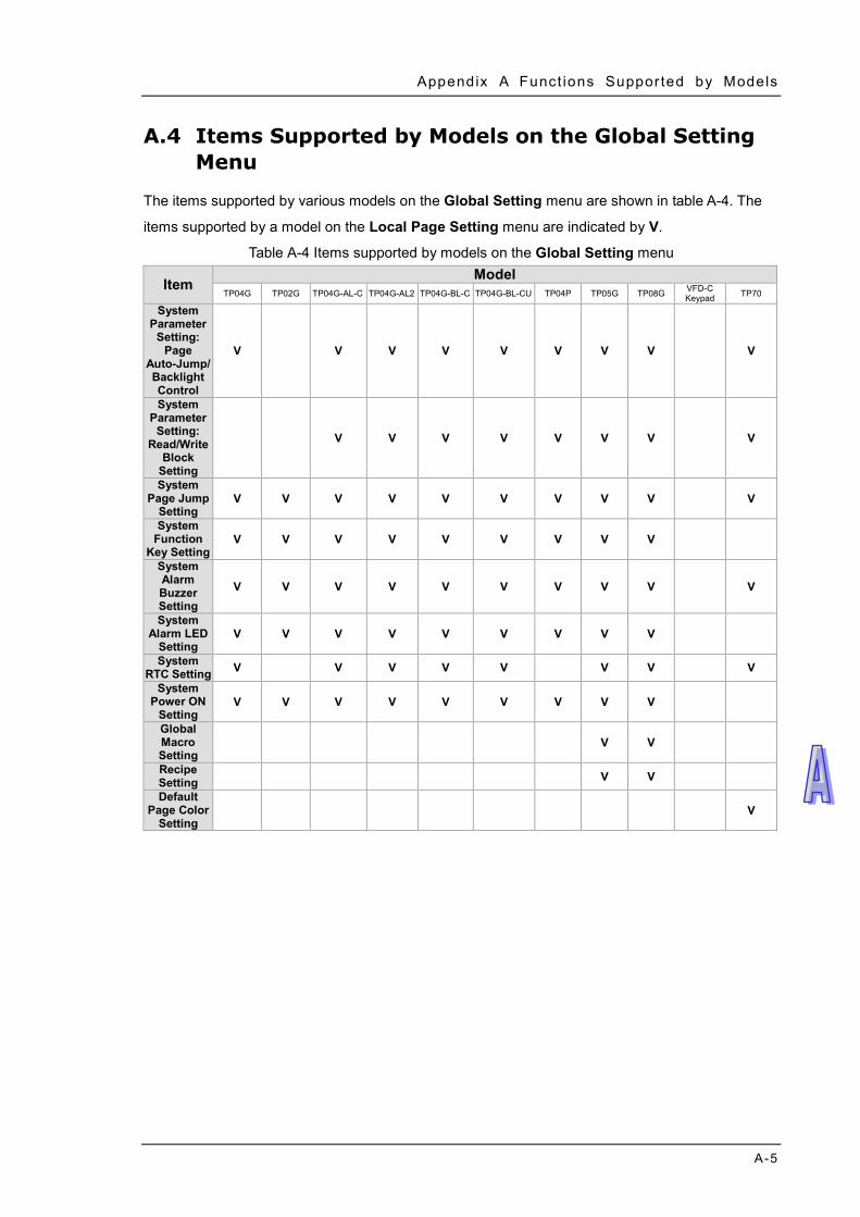
Appendix A Funct ions Suppor ted by Models
A-5
A.4 Items Supported by Models on the Global Setting Menu
The items supported by various models on the Global Setting menu are shown in table A-4. The
items supported by a model on the Local Page Setting menu are indicated by V.
Table A-4 Items supported by models on the Global Setting menu
Item Model
TP04G TP02G TP04G-AL-C TP04G-AL2 TP04G-BL-C TP04G-BL-CU TP04P TP05G TP08G VFD-C Keypad TP70
System Parameter
Setting: Page
Auto-Jump/Backlight Control
V V V V V V V V V
System Parameter
Setting: Read/Write
Block Setting
V V V V V V V V
System Page Jump
Setting V V V V V V V V V V
System Function
Key Setting V V V V V V V V V
System Alarm Buzzer Setting
V V V V V V V V V V
System Alarm LED
Setting V V V V V V V V V
System RTC Setting V V V V V V V V
System Power ON
Setting V V V V V V V V V
Global Macro Setting
V V Recipe Setting V V Default
Page Color Setting
V

TPEditor User Manual
A-6
MEMO

B-1
Appendix B USB Driver Contents B.1 Installing a USB Driver ............................................................................. B-2
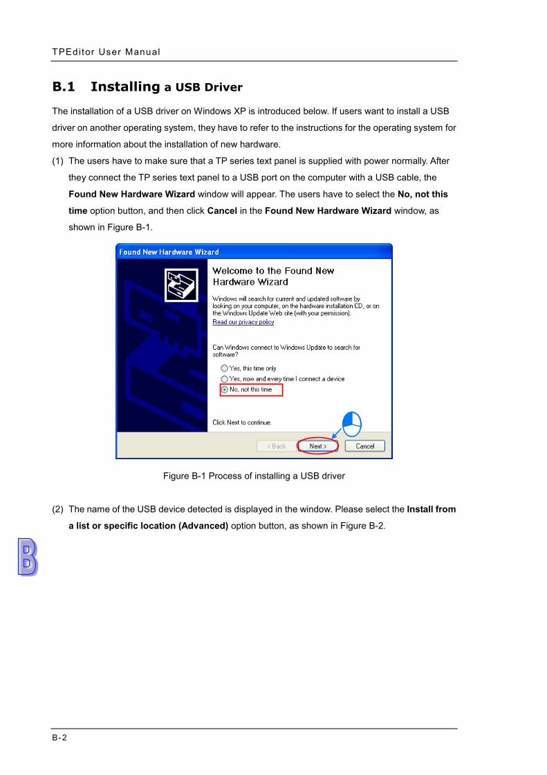
TPEditor User Manual
B-2
B.1 Installing a USB Driver
The installation of a USB driver on Windows XP is introduced below. If users want to install a USB
driver on another operating system, they have to refer to the instructions for the operating system for
more information about the installation of new hardware.
(1) The users have to make sure that a TP series text panel is supplied with power normally. After
they connect the TP series text panel to a USB port on the computer with a USB cable, the
Found New Hardware Wizard window will appear. The users have to select the No, not this
time option button, and then click Cancel in the Found New Hardware Wizard window, as
shown in Figure B-1.
Figure B-1 Process of installing a USB driver
(2) The name of the USB device detected is displayed in the window. Please select the Install from
a list or specific location (Advanced) option button, as shown in Figure B-2.
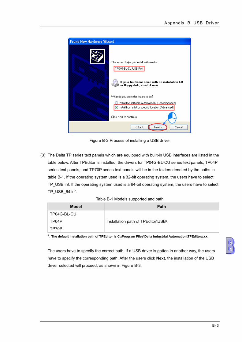
Appendix B USB Dr iver
B-3
Figure B-2 Process of installing a USB driver
(3) The Delta TP series text panels which are equipped with built-in USB interfaces are listed in the
table below. After TPEditor is installed, the drivers for TP04G-BL-CU series text panels, TP04P
series text panels, and TP70P series text panels will be in the folders denoted by the paths in
table B-1. If the operating system used is a 32-bit operating system, the users have to select
TP_USB.inf. If the operating system used is a 64-bit operating system, the users have to select
TP_USB_64.inf.
Table B-1 Models supported and path
Model Path
TP04G-BL-CU
TP04P
TP70P
Installation path of TPEditor\USB\
*. The default installation path of TPEditor is C:\Program Files\Delta Industrial Automation\TPEditorx.xx.
The users have to specify the correct path. If a USB driver is gotten in another way, the users
have to specify the corresponding path. After the users click Next, the installation of the USB
driver selected will proceed, as shown in Figure B-3.
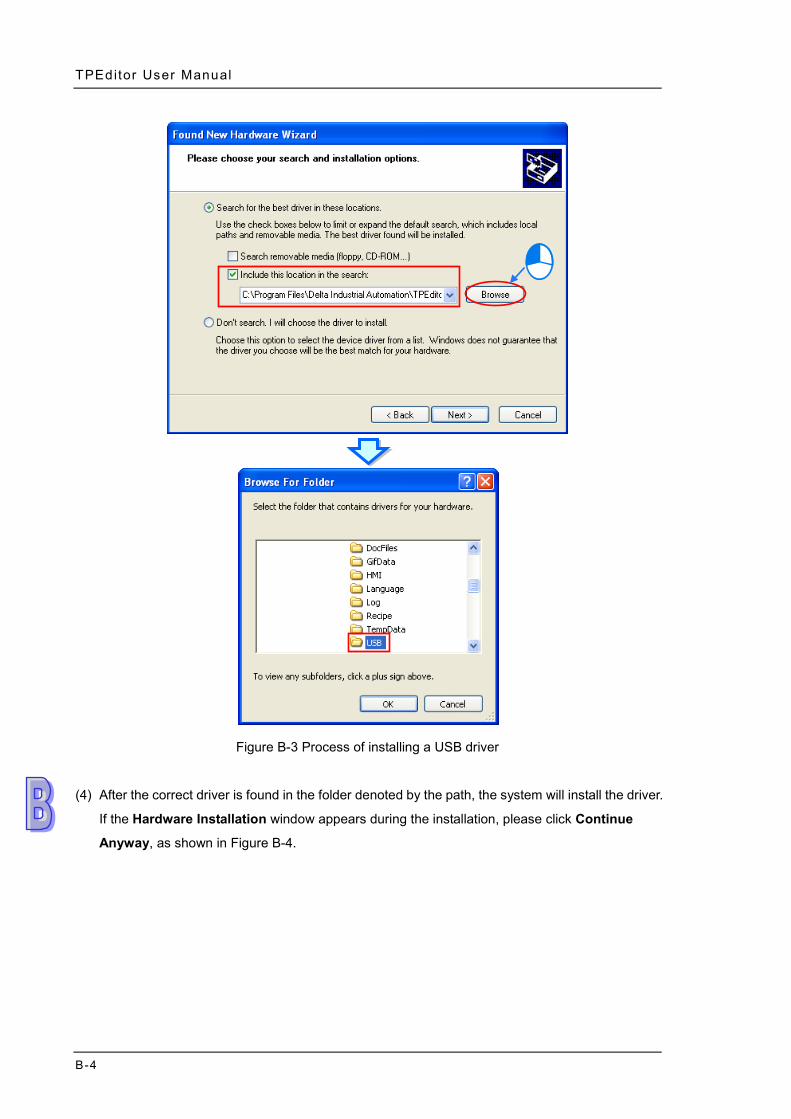
TPEditor User Manual
B-4
Figure B-3 Process of installing a USB driver
(4) After the correct driver is found in the folder denoted by the path, the system will install the driver.
If the Hardware Installation window appears during the installation, please click Continue
Anyway, as shown in Figure B-4.
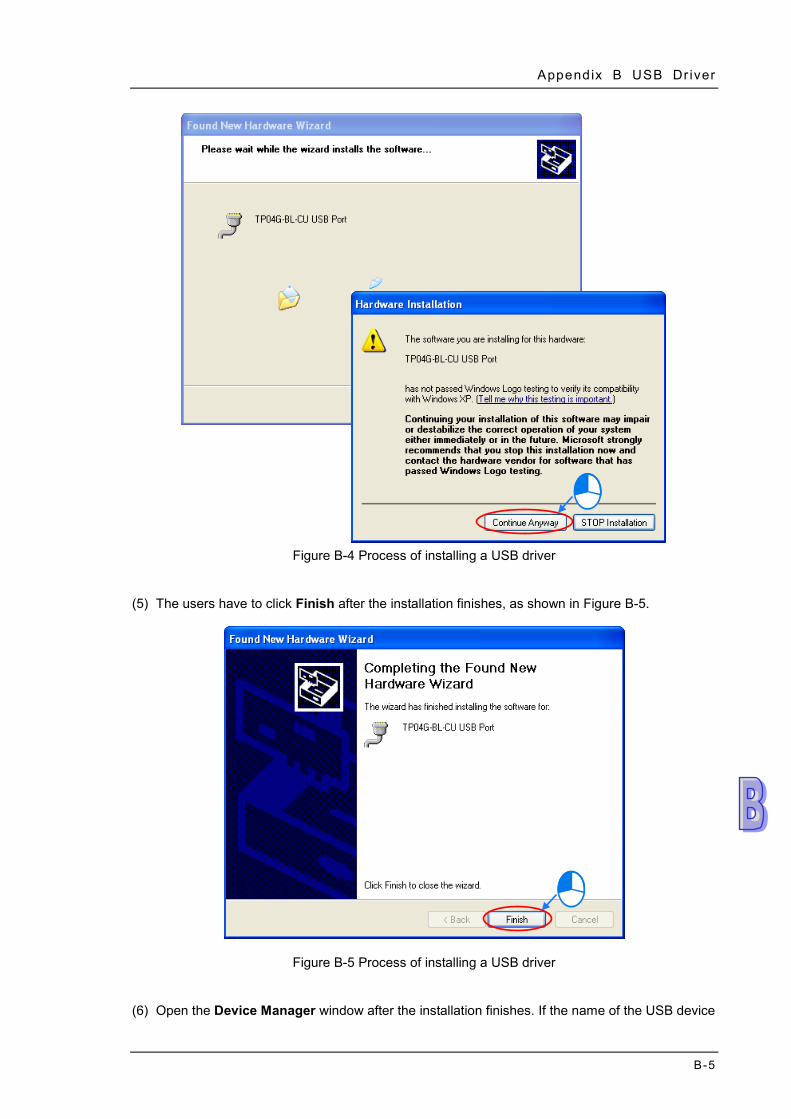
Appendix B USB Dr iver
B-5
Figure B-4 Process of installing a USB driver
(5) The users have to click Finish after the installation finishes, as shown in Figure B-5.
Figure B-5 Process of installing a USB driver
(6) Open the Device Manager window after the installation finishes. If the name of the USB device
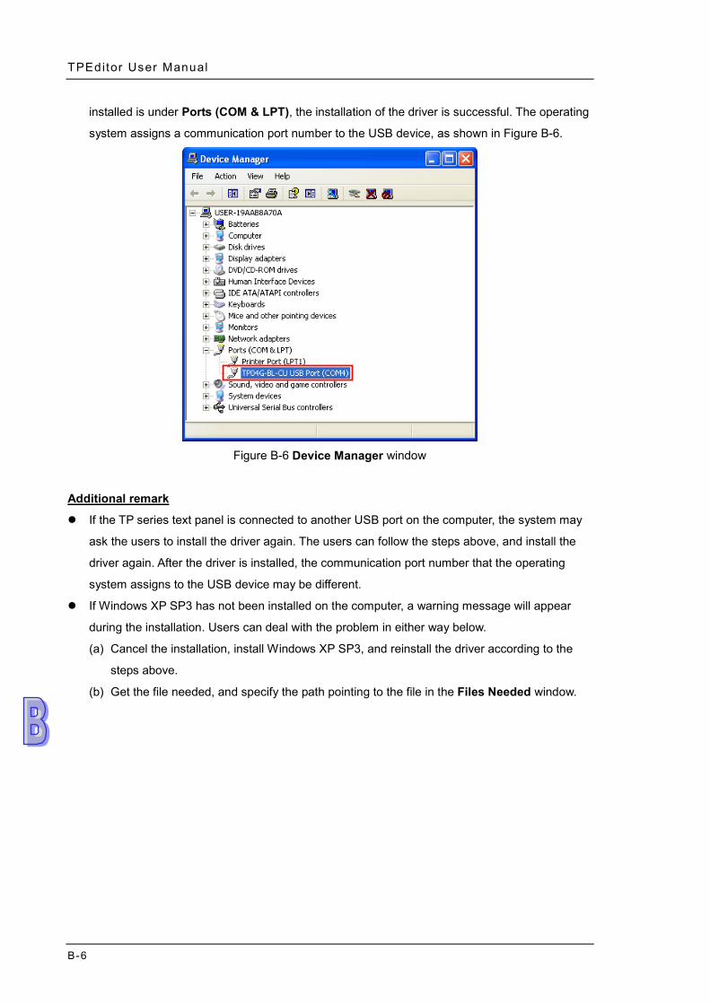
TPEditor User Manual
B-6
installed is under Ports (COM & LPT), the installation of the driver is successful. The operating
system assigns a communication port number to the USB device, as shown in Figure B-6.
Figure B-6 Device Manager window
Additional remark
If the TP series text panel is connected to another USB port on the computer, the system may
ask the users to install the driver again. The users can follow the steps above, and install the
driver again. After the driver is installed, the communication port number that the operating
system assigns to the USB device may be different.
If Windows XP SP3 has not been installed on the computer, a warning message will appear
during the installation. Users can deal with the problem in either way below.
(a) Cancel the installation, install Windows XP SP3, and reinstall the driver according to the
steps above.
(b) Get the file needed, and specify the path pointing to the file in the Files Needed window.