tp223 practices - sediment control f...sediment control practices 52 tp223 - forestry operations in...
TRANSCRIPT

Sediment Control Practices 50
TP223 - Forestry operations in the Auckland region A guideline for erosion and sediment control
7.0 SEDIMENT CONTROL PRACTICES
There are numerous types of sediment control measures that can be used. Those common to the forest industry include silt traps, decanting earth bunds, silt fences, debris dams, haybale barriers and sediment retention ponds. Details associated with these control options follow in this section.
Two fundamental matters to note with sediment control measures are:
1. The maximum area of catchment for most control measures is small (e.g. the maximum catchment for a silt trap is 0.5ha and for a decanting earth bund is 0.3 hectares); and,
2. All of the catchment draining to a sediment retention measure needs to be included in the assessment (not just the bare area alone). Runoff diversion measures (see section 6.3.1) that divert clean water away from sediment control measures, reduce the catchment required for the treatment systems. This therefore reduces the volume required for the sediment controls.
The sediment control practices in this section include:
Practice
Maximum Operating Catchment Area
Haybale Barrier 1,000 m2 Earth Bund 1,000 m2 Slash Bund 1,000 m2 Decanting Earth Bund 3,000 m2 Silt Fence 5,000 m2 Super Silt Fence (“Debris Dams”) 5,000 m2 Silt Trap 5,000 m2 Sediment Retention Pond 5.0 ha

Sediment Control Practices 51
TP223 - Forestry operations in the Auckland region A guideline for erosion and sediment control
7.1 Haybale Barriers
Photo 7.1 Hay Bale Barrier Description/Purpose
These are used as temporary sediment retention devices for very small catchments. They can be useful as impermeable barriers and to intercept and divert site runoff. However, they do not filter sediment effectively and are often prone to flow short-circuiting around the haybales.
Catchment Area
Less than 0.1 hectare. Generally there should be no more than 20 m of upslope behind this measure.
Construction
a) Place in a row along the contour and butt them tightly together. Turn the ends up to capture runoff if they are being used for sediment retention.
b) Butt each bale up to the previous bale and stake each bale with 2 stakes driven 300 mm into the ground. The first stake in each bale should be driven towards the previously laid bale to force the bales together. Holes under or between the bales need to be securely plugged with clay.

Sediment Control Practices 52
TP223 - Forestry operations in the Auckland region A guideline for erosion and sediment control
Construction Notes: a) They do not filter runoff and are therefore mini dams. b) They can get very heavy when wet and difficult to shift. c) They are commonly used in situations beyond their capability.
Maintenance
Develop a maintenance and monitoring schedule to ensure that these controls are operating effectively and, to look for any changes in the structure. Important details to check on are: a) They can be removed after rainfall. Otherwise, inspect and repair after each rainfall
event. b) Remove sediment when half way up the bale if they are being used as a sediment
retention device.

Sediment Control Practices 53
TP223 - Forestry operations in the Auckland region A guideline for erosion and sediment control
Drawing
Figure 7.1 Hay Bale Barrier
Sediment Control Practices 54
TP223 - Forestry operations in the Auckland region A guideline for erosion and sediment control
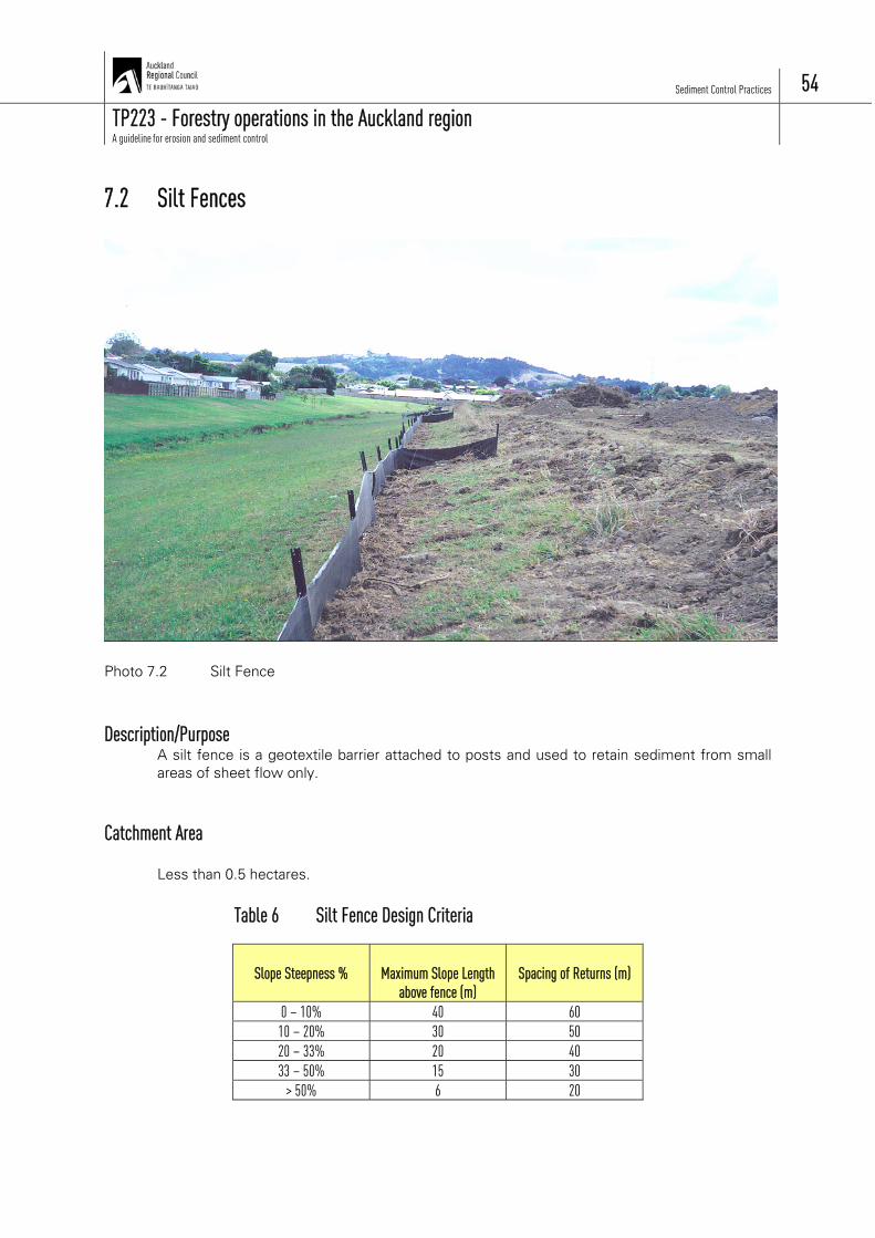
7.2 Silt Fences
Photo 7.2 Silt Fence Description/Purpose
A silt fence is a geotextile barrier attached to posts and used to retain sediment from small areas of sheet flow only.
Catchment Area
Less than 0.5 hectares.
Table 6 Silt Fence Design Criteria
Slope Steepness %
Maximum Slope Length
above fence (m)
Spacing of Returns (m)
0 – 10% 40 60 10 – 20% 30 50 20 – 33% 20 40 33 – 50% 15 30
> 50% 6 20

Sediment Control Practices 55
TP223 - Forestry operations in the Auckland region A guideline for erosion and sediment control
Construction
a) The silt fence should be positioned on the contour where possible. Install “returns” at the spacings shown in Table 6 above. A return is a minimum 2m of silt fence constructed at right angles to the main silt fence, and used for retention areas.
b) Dig a 200 mm deep trench along the silt fence. c) Install posts/waratahs on the lower side of the trench at maximum 2 metre centres
and to at least 400 mm height. d) Install a tensioned wire (2.5 HT) along the top of the fence. Tie this back at either end
for strength. e) Install the silt fence fabric along the fence and secure to the posts and wire. f) Backfill the trench to anchor the fabric 200 mm into the ground. Compact firmly to
ensure that the fence is not undercut. g) Install tie backs at low points for additional strength.
Construction Notes: a) Use proprietary silt fence fabrics only (from fabric manufacturers/suppliers).
Refer Table 7 below for minimum specifications. b) Join lengths of silt fence by overlapping, folding and fastening e.g. by stapling
to a wooden batten or similar. c) A silt fence can be reinforced with sheep netting, chain mesh netting or
similar behind it. Note that this strengthening netting must also be dug into the ground.
d) Do not use them across flowing watercourses or similar areas of concentrated flow as they do not have the strength to stand the energy of concentrated flows.
e) They can be useful for delineating features such as wetlands and similar from work areas.
Table 7 Silt Fence – Minimum Performance Requirements
Properties
Rating
Tension Strength >440N, (ASTM D4632) Tensile Modulus 0.140pa (minimum) Apparent Opening Size 0.1-0.5mm, (ASTM D4751)
Maintenance
Silt fences are only as good as their maintenance. Develop a maintenance and monitoring schedule to ensure that these controls are operating effectively and, to look for any changes in the structure. Important details to check on are: a) Inspect the fence on a weekly basis and after heavy rain (15mm in the preceding 24
hours) and repair as necessary. They often fail by being undercut. b) Remove accumulated sediment when it causes bulges in the fence. c) If there is an outfall, then ensure that it remains stable (use slash, fabric etc).

Sediment Control Practices 56
TP223 - Forestry operations in the Auckland region A guideline for erosion and sediment control
Drawing
Figure 7.2 Silt Fence Details

Sediment Control Practices 57
TP223 - Forestry operations in the Auckland region A guideline for erosion and sediment control
7.3 Super Silt Fences (“Debris Dams”)
Photo 7.3 Super silt fence used as a debris dam to contain mobilised sediment Description/Purpose
These are small but strong sediment retention barriers made of filter fabric, timber, rock etc. They are often constructed in areas of actively moving surface soil or slip material. Typical forestry use includes forming a tightly compressed bund of slash (refer Section 7.4-Slash Bunds) just below the slip material in such a way that there is sufficient bulk (or constructed support using a super silt fence as described below) in the bund to hold the slip material in place. Generally, additional treatment measures would be installed below the debris dam to treat the runoff of finer sediment.
Catchment Area
Less than 0.5 hectares. Construction
a) The debris dam should be no more than 500 mm in height at the centre to prevent it from being destroyed by “waves” of sediment.

Sediment Control Practices 58
TP223 - Forestry operations in the Auckland region A guideline for erosion and sediment control
b) The sides of the debris dam must be higher than the centre so that the flow is always directed to the centre of the dam (this avoids the debris dam being outflanked). Energy dissipation at the outfall is required.
c) The crest of the downstream dam should be at about the same elevation as the toe of the upstream dam. The spacing between dams therefore varies with slope angle.
d) Supports (e.g. waratahs) should be no more than 1 metre apart in the centre and driven a minimum of 500 mm into ground. Spacing can be increased to 1.5 metres on banks.
e) In the case of a fabric dam (refer Figure 7.3), the geotextile needs to be strengthened with chain mesh or boundary fence netting.
f) Dig the material into the ground to avoid the dam being undercut. If fabric is used (refer required properties in Table 7, Section 7.2), this, plus the strengthening wire netting, needs to be dug at least 300 mm into the ground.
g) The middle of debris dams should be tied back with No. 8 wire to deadmen at least 2 metres upstream of the dam. Deadmen can be steel posts or similar angled back to dam and driven at least 500 mm into the ground. Tie back either end of the dam in a similar fashion as well.
Construction Notes: a) Debris dams should be positioned as close to the sediment source as
possible and extended down from that point. b) They should be built in a semi-circular shape for strength. c) Once filled with sediment, more dams may be constructed by positioning the
new ones half way between the existing dams. Maintenance
Debris dams can hold large volumes of relatively mobile sediment and any weakness in the structure will quickly become apparent. The most common causes of failure are the undercutting or outflanking of the measure. Therefore: a) Ensure that flow is not flowing either under or around the debris dam. b) Inspect regularly and after every storm event (15mm in the preceding 24 hours). c) Implement repairs to ensure the dams remain in good working order. d) Check to ensure that no erosion is occurring at the outfall.

Sediment Control Practices 59
TP223 - Forestry operations in the Auckland region A guideline for erosion and sediment control
Drawing
Figure 7.3 Super Silt Fence
Sediment Control Practices 60
TP223 - Forestry operations in the Auckland region A guideline for erosion and sediment control
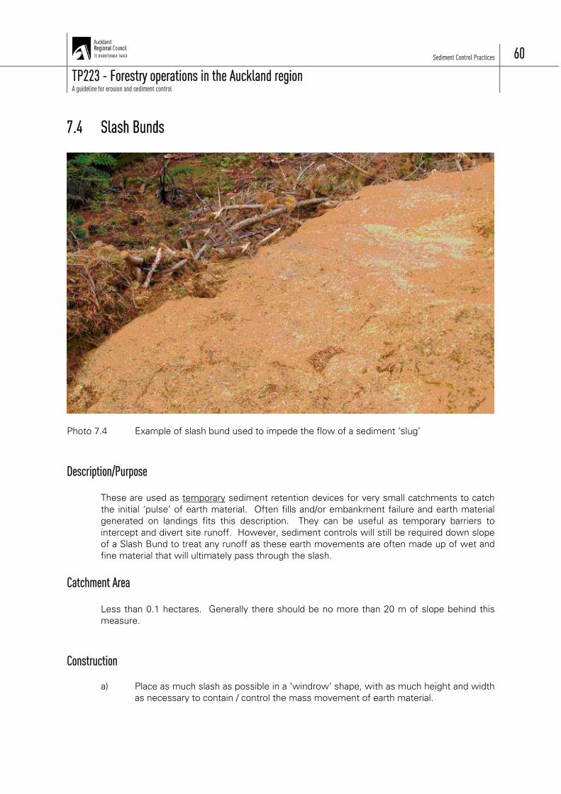
7.4 Slash Bunds
Photo 7.4 Example of slash bund used to impede the flow of a sediment ‘slug’ Description/Purpose
These are used as temporary sediment retention devices for very small catchments to catch the initial ‘pulse’ of earth material. Often fills and/or embankment failure and earth material generated on landings fits this description. They can be useful as temporary barriers to intercept and divert site runoff. However, sediment controls will still be required down slope of a Slash Bund to treat any runoff as these earth movements are often made up of wet and fine material that will ultimately pass through the slash.
Catchment Area
Less than 0.1 hectares. Generally there should be no more than 20 m of slope behind this measure.
Construction
a) Place as much slash as possible in a ‘windrow’ shape, with as much height and width as necessary to contain / control the mass movement of earth material.

Sediment Control Practices 61
TP223 - Forestry operations in the Auckland region A guideline for erosion and sediment control
b) The weight of the slash needs to be equal to the weight of the material pushing against it and in extreme cases may need large logs in critical areas to provide the necessary support.
c) These bunds do not provide filtration of finer sediments and some form of sediment control maybe necessary below these slash bunds to control the finer sediment material that passes through the bunds.
Construction Notes: a) They are not effective sediment filters and are recommended just to stop the
viscous earth material migrating to sensitive areas. b) Controlling the viscous material at the source will usually mean it is easier to
construct sediment controls below the material being contained. c) Divert any upper catchment flows around the site as any flows will
compound the problems with such loose / fine material. d) They are often mistakenly used as the only form of sediment control.
Maintenance
Develop a maintenance and monitoring schedule to ensure that these controls are operating effectively and, to look for any changes in the structure. Important details to check on are: a) Check for breaches or failures of the slash bund, particularly where the most weight
is being exerted from the sloppy earth movement. b) Where pressure is beginning to exceed the ability of the slash bund to hold back the
sloppy earth material, add further slash and logs to strengthen. c) Check that the sediment controls below the bunds are functioning and clean out as
required.
Sediment Control Practices 62
TP223 - Forestry operations in the Auckland region A guideline for erosion and sediment control
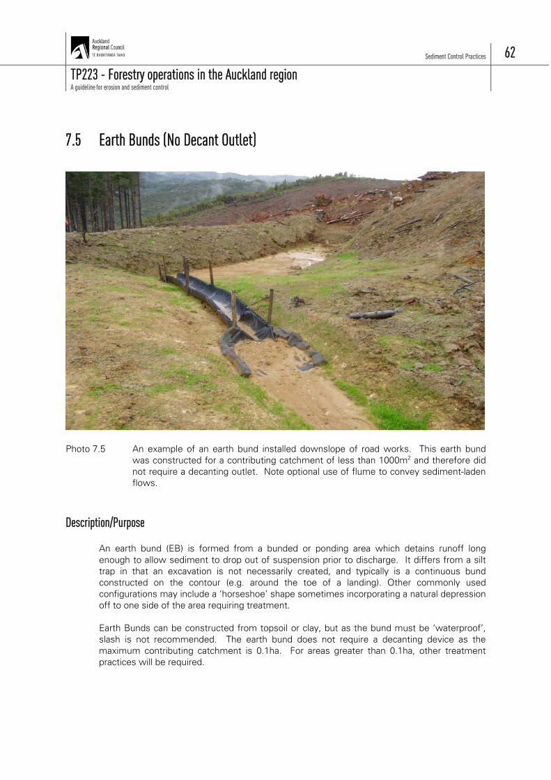
7.5 Earth Bunds (No Decant Outlet)
Photo 7.5 An example of an earth bund installed downslope of road works. This earth bund
was constructed for a contributing catchment of less than 1000m2 and therefore did not require a decanting outlet. Note optional use of flume to convey sediment-laden flows.
Description/Purpose
An earth bund (EB) is formed from a bunded or ponding area which detains runoff long enough to allow sediment to drop out of suspension prior to discharge. It differs from a silt trap in that an excavation is not necessarily created, and typically is a continuous bund constructed on the contour (e.g. around the toe of a landing). Other commonly used configurations may include a ‘horseshoe’ shape sometimes incorporating a natural depression off to one side of the area requiring treatment. Earth Bunds can be constructed from topsoil or clay, but as the bund must be ‘waterproof’, slash is not recommended. The earth bund does not require a decanting device as the maximum contributing catchment is 0.1ha. For areas greater than 0.1ha, other treatment practices will be required.

Sediment Control Practices 63
TP223 - Forestry operations in the Auckland region A guideline for erosion and sediment control
Catchment Area
Less than 0.1 hectare. Construction
a) Work out how the Earth Bund will fit in/work for the site. Identify the catchment area (more than one Earth Bund may be necessary). Discuss with the harvesting contractor where ground based haul tracks will access and exit the landing and avoid placing controls where damage from these activities is likely to occur. The same considerations are necessary for haulers as often a single setting can result in trees being hauled over most of the landing edges.
b) Construct a 1.5 m high earth bund (maximum height) at the selected point. The embankment must be compacted. The bund must provide a minimum storage volume behind the bund equivalent to 2m3 for each 100m2 of catchment. Extend the bund so that the runoff from the required catchment can be intercepted and directed to the Earth Bund for treatment. If an excavation is created the sides should be no steeper than 1:1.
c) Inlet points must be located as far as possible away from the outlet to optimise sediment deposition. Ideally the Earth Bund should be 3 times longer than it is wide with inflow at one end and the outlet at the other.
d) Any discharge from the Earth Bund must be to an erosion proof outlet e.g. to slash, a natural depression/watercourse etc. Do not discharge over bare land, fill or unstable ground. If necessary, the outflow may need to be flumed to an erosion proof discharge point.
e) Remove Earth Bunds when the catchment has been stabilised and stabilise the remaining bare area (such as with grass seed, slash etc).
Construction Notes: a) Do not install them above unstable slopes as infiltration and the loading
surcharge may exacerbate instability. Remove all vegetation prior to construction. They may need to be keyed in on steep slopes.
b) Subsoil is the preferred material to construct embankments and this material must be compacted. If topsoil is used, the embankment is to be a minimum of 4 m wide, with 1:1 batters and compacted.
c) The minimum height for the diversion bunds can be 0.75 m (bunds that direct runoff to treatment areas but have no impounding function) but ensure that they are always higher than the spillway. The spillway must always be at the lowest point of the bund.
d) Slash or unsuitable organic material can be placed immediately below the bunds as it can provide some structural support as well as a stabilisation function.
Maintenance
Develop a maintenance and monitoring schedule to ensure that these controls are operating effectively and, to look for any changes in the structure. Important details to check on are: a) Make sure that runoff is not outflanking the system.
Sediment Control Practices 64
TP223 - Forestry operations in the Auckland region A guideline for erosion and sediment control
b) Make sure that the spillway is the lowest point over the bund wall, that it is functional and protected against erosion. Repair any damage.
c) Check for erosion at the outfall and remedy as required (e.g. redirect to a new outlet, install a flume etc).
d) Repair any damage to the drainage systems. e) Inspect for seepage through the embankment and repair as necessary. f) Remove accumulated sediment when the Earth Bund is no longer working to volume
criteria (generally when 20 % full of sediment). Place the soil away so it can’t wash back into the Earth Bund or into natural water etc.
g) Repair immediately if the Earth Bund has been damaged by logging operations.
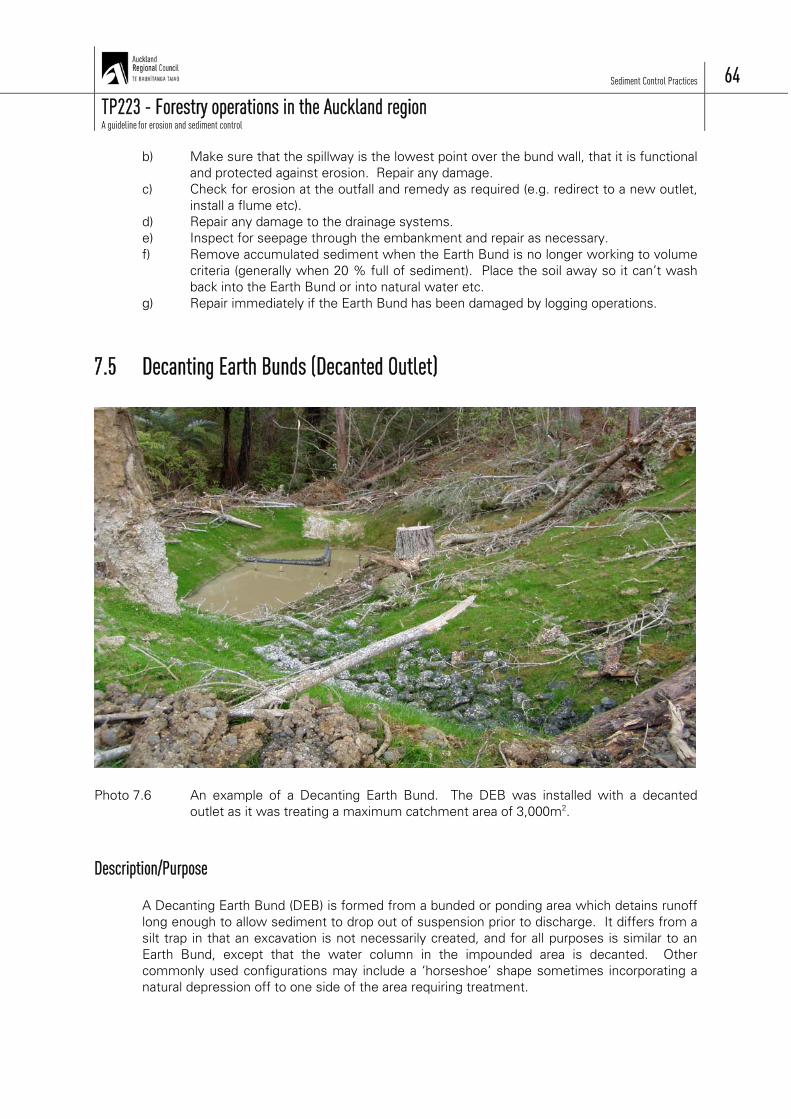
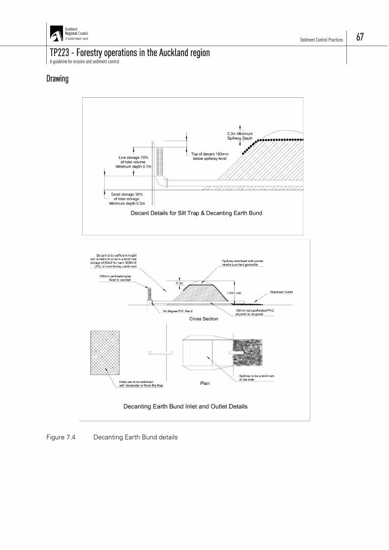
7.5 Decanting Earth Bunds (Decanted Outlet)
Photo 7.6 An example of a Decanting Earth Bund. The DEB was installed with a decanted
outlet as it was treating a maximum catchment area of 3,000m2. Description/Purpose
A Decanting Earth Bund (DEB) is formed from a bunded or ponding area which detains runoff long enough to allow sediment to drop out of suspension prior to discharge. It differs from a silt trap in that an excavation is not necessarily created, and for all purposes is similar to an Earth Bund, except that the water column in the impounded area is decanted. Other commonly used configurations may include a ‘horseshoe’ shape sometimes incorporating a natural depression off to one side of the area requiring treatment.

Sediment Control Practices 65
TP223 - Forestry operations in the Auckland region A guideline for erosion and sediment control
Decanting Earth Bunds can be constructed from topsoil or clay, but as the bund must be ‘waterproof’, slash is not recommended. The Decanting Earth Bund is required to have a decant outlet device, and due to this higher level of treatment (sediment removal) has a maximum contributing catchment is 0.3ha. For areas greater than 0.3ha, other treatment practices (silt traps, sediment retention ponds) will be required.
Catchment Area
Less than 0.3 hectares. Construction
a) Work out how the Decanting Earth Bund will fit in (work) for the site. Identify the catchment area (more than one Decanting Earth Bund may be necessary). Discuss with the harvesting contractor where ground based haul tracks will access and exit the landing and avoid placing controls where damage from these activities is likely to occur. The same considerations are necessary for haulers as often a single setting can result in trees being hauled over most of the landing edges.
b) Construct a 1.5 m high earth bund (maximum height) at the selected point. The embankment must be compacted. The bund must provide a minimum storage volume behind the bund equivalent to 2m3 for each 100m2 of catchment. Extend the bund so that the runoff from the required catchment can be intercepted and directed to the Decanting Earth Bund for treatment. If an excavation is created the sides should be no steeper than 1:1.
c) Inlet points must be located as far as possible away from the outlet to optimise sediment deposition. Ideally the Decanting Earth Bund should be 3 times longer than it is wide with inflow at one end and the outlet at the other – a baffle may be necessary to achieve this.
d) Lay a 150 mm diameter non perforated drainage pipe through the bund at the low point and compact soil firmly around the pipe. The pipe needs to discharge to an erosion proof outlet e.g. to slash, a natural depression/watercourse etc. Do not discharge over bare land, fill or unstable ground. If necessary, the outflow may need to be flumed to an erosion proof discharge point.
e) Install a decanting upstand. Place a 90-degree bend on the inside end of the outlet pipe near the bund wall and install a vertical pipe so that the top is no more than 1 m from the ground. Securely glue/fasten all connections. Drill 6 rows of 5 mm diameter holes at 50 mm spacing for drainage from the top of the upstand down to 0.3 m from the silt trap floor. This will result in a permanent pool at the bottom of the Silt Trap, which aids sediment treatment. [Note: 1/3 of the volume of the trap should be “dead storage” i.e. a pool of water and the other 2/3 is operating volume i.e. is the volume decanted off through the perforated upstand during and after rainfall events].
f) Drive a waratah into the ground next together and wire together for support. g) Install a 2.0 metre wide trapezoidal spillway over the Decanting Earth Bund
(preferably to spill to natural land). This must be level across its width and 150 mm above the invert of the upstand. Stabilise the surface of the spillway against erosion if the down slope is more than 2% (e.g. with geotextile fabric, rock [150-300 mm diameter], slash, or concrete).
h) Remove Decanting Earth Bund‘s when the catchment has been stabilised and stabilise the remaining bare area (such as with grass seed, slash etc).

Sediment Control Practices 66
TP223 - Forestry operations in the Auckland region A guideline for erosion and sediment control
Construction Notes: a) Do not install them above unstable slopes as infiltration and the loading
surcharge may exacerbate instability. Remove all vegetation that will compromise the geotechnical integrity of the structure prior to construction. They may need to be keyed in on steep slopes.
b) Subsoil is the preferred material to construct embankments and this material must be compacted. If topsoil is used, the embankment is to be a minimum of 4 m wide, 1:1 batters and compacted.
c) The minimum height for the diversion bunds can be 0.75 m (bunds that direct runoff to treatment areas but have no impounding function) but ensure that they are always higher than the spillway. The spillway must always be at the lowest point of the bund.
d) Compact carefully around the drainage pipe through the embankment to avoid seepage and potential trap failure.
e) Surround the perforated upstand with chicken mesh to keep bark, slash etc from blocking the drainage holes in the upstand.
f) Slash or unsuitable organic material can be placed immediately below the bunds as it can provide some structural support as well as a stabilisation function.
Maintenance
Develop a maintenance and monitoring schedule to ensure that these controls are operating effectively and, to look for any changes in the structure. Important details to check on are: a) Make sure that runoff is not outflanking the system. b) Make sure that the spillway is the lowest point over the bund wall, that it is functional
and protected against erosion. Repair any damage. c) Check for erosion at the outfall and remedy as required (e.g. redirect to a new outlet,
install a flume etc). d) Repair any damage to the pipe drainage systems. a) Inspect for seepage through the embankment, or along the outlet pipe and repair as
necessary. b) Repair any blockages such as to the holes in the upstand etc. c) Remove accumulated sediment when the Earth Bund is no longer working to volume
criteria (generally when 20 % full of sediment). Place the soil away so it can’t wash back into the Earth Bund or into natural water etc.
d) Repair immediately if the Decanting Earth Bund has been damaged by logging operations.
Sediment Control Practices 67
TP223 - Forestry operations in the Auckland region A guideline for erosion and sediment control
Drawing
Figure 7.4 Decanting Earth Bund details

Sediment Control Practices 68
TP223 - Forestry operations in the Auckland region A guideline for erosion and sediment control
7.7 Silt Traps Photo 7.7 Silt Trap Description/Purpose
A Silt Trap is a small sediment retention pond system rather like a mini sediment retention pond. They can be formed by excavation and/or embankment. They also have ‘stricter’ design criteria than Decanting Earth Bunds and can therefore treat larger areas.
Catchment Area
Less than 0.5 hectares. Construction
a) Work out how the silt trap will fit in/work for the site. Identify the catchment area as more than one Silt Trap may be necessary. Discuss with the harvesting contractor where ground based haul tracks will access and exit the landing and avoid placing controls where damage is likely to occur. The same considerations are necessary for haulers as often a single setting can result in trees being hauled over most of the landing edges, causing damage to controls.

Sediment Control Practices 69
TP223 - Forestry operations in the Auckland region A guideline for erosion and sediment control
b) Diversion channels/bunds will usually be necessary to intercept and direct site runoff to the Silt Trap for treatment.
c) Construct the Silt Trap at the selected point ensuring that the bund or excavation is no more than 1.5 m high. The created storage area must provide a minimum storage volume equivalent to 2m3 for each 100m2 of contributing catchment (2% criteria). The bottom of the trap should be level and flat and the sides no steeper than 1:1.
d) Silt Trap embankments may need to be keyed in on steep slopes. e) The inlet to the Silt Trap should be 3 horizontal: 1 vertical and be as wide as the floor
of the Silt Trap. This inlet will usually need to be stabilised e.g. with geotextiles. It must be located as far as possible away from the outlet to optimise sediment deposition.
f) The Silt Trap should be 3 times longer than it is wide with inflow entering at one end and the discharging through the outlet at the other. Baffles may be necessary to achieve this. A baffle is a barrier constructed across the pond to direct flows and so maximise the efficiency of the Silt Trap. Its height should be the same as that of the top of the perforated upstand. It can be constructed from fabric such as silt fence fabric or shaped when being excavated leaving a clay barrier. When using clay barriers, the top must be covered with fabric or similar to guard against erosion. If erosion over the barrier cannot be prevented, the secondary part of the pond will then form the silt trap (i.e. it must have 2m3 for every 100 m2 of catchment) and the first stage becomes a fore bay that will retain larger soil particles (and aid cleaning).
g) Lay a 150 mm diameter non-perforated drainage pipe through the bund at the low point and compact soil firmly around the pipe. The pipe needs to discharge to an erosion resistant outlet e.g. to slash, a natural depression/watercourse etc. Do not discharge over bare land, fill or unstable land. If necessary, the outflow may need to be flumed to an erosion resistant discharge point.
h) Install the upstand. Place a 90-degree bend on the inside end of the outlet pipe near the bund wall and install a vertical pipe so that the top is no more than 1 m from the ground. Securely glue/fasten all connections. Drill 6 rows of 5 mm diameter holes at 50 mm spacing for drainage from the top of the upstand down to 0.3 m from the silt trap floor. This will result in a permanent pool at the bottom of the Silt Trap which aids sediment treatment. [Note: 1/3 of the volume of the trap should be “dead storage” i.e. a pool of water and the other 2/3 is operating volume i.e. is the volume decanted off through the perforated upstand during and after rainfall events].
i) Drive a waratah into the ground next to the upstand and wire together for support. j) Install a 2.0 metre wide trapezoidal spillway over the Silt Trap embankment
(preferably to spill to natural land). This must be level across its width and 100 mm above the invert of the upstand i.e. no higher than 1.1 m above the floor of the trap. Stabilise the surface of the spillway against erosion if the down slope is more than 2% (e.g. with geotextile fabric, rock [150-300 mm diameter], slash, or concrete).
k) Remove Silt Trap when the catchment has been stabilised and stabilise the remaining bare area ( with grass seed, slash etc).
Construction Notes: a) Do not install them above unstable slopes as seepage may cause slumping. b) Remove all vegetation prior to construction. c) Subsoil is the preferred material to construct embankments and this material
must be compacted. If topsoil is used, the embankment is to be a minimum of 4 m wide, have 1:1 batters and be compacted.
d) The minimum height of the diversion bunds can be 0.75 m (bunds that direct runoff to treatment areas but have no impounding function) but ensure that they are always higher than the spillway. The spillway must always be the lowest point of the embankment.
Sediment Control Practices 70
TP223 - Forestry operations in the Auckland region A guideline for erosion and sediment control
e) Compact carefully around the drainage pipe through the embankment to avoid seepage and potential trap failure.
f) Surround the perforated upstand with chicken mesh to keep bark, slash etc from blocking the drainage holes in the upstand.
g) Slash or unsuitable organic material can be placed immediately below the bunds.
Maintenance
Develop a maintenance and monitoring schedule to ensure that these controls are operating effectively and, to look for any changes in the structure. Important details to check on are:
a) Make sure that runoff is not outflanking the system. b) Make sure that the spillway is the lowest point of the embankment, that it is
functional and protected against erosion. Repair any damage. c) Check for erosion at the outfall and remedy as required (e.g. redirect to a new outlet,
install a flume etc). d) Repair any damage to the pipe drainage systems. e) Inspect for seepage through the embankment or along the outlet pipe and repair as
necessary. f) Repair any blockages such as holes in the upstand etc. g) Remove accumulated sediment when the Silt Trap is no longer working to volume
criteria (generally when 20 % full of sediment). Place the soil away so it can’t wash back into the Earth Bund or into natural water etc.
h) Repair immediately if the Silt Trap has been damaged by logging operations.

Sediment Control Practices 71
TP223 - Forestry operations in the Auckland region A guideline for erosion and sediment control
Drawing
Figure 7.5 Design criteria of a Silt Trap

Sediment Control Practices 72
TP223 - Forestry operations in the Auckland region A guideline for erosion and sediment control
7.8 Sediment Retention Ponds Photo 7.8 Sediment Retention Pond Description/Purpose
These are specifically designed ponds used to treat site runoff and retain sediment. This facility is the usual treatment measure for urban earthwork sites treating catchments larger than 0.5 hectares in the Auckland region. It should be noted that TP90 compliant sediment retention ponds are complex and expensive to construct and consequently are not often used in forestry in the Auckland region.
Catchment Area
Less than 5 hectares. Construction
Sediment retention ponds are now complex devices and require specific design and construction. The following information introduces this measure but TP 90 (Erosion and Sediment Control Guidelines for the Auckland Region) should be referred to for more definitive detail. a) The pond usually has a volume of 300 m3 to every hectare of contributing catchment.
The pond has a piped outlet and the volume is calculated from the floor of the pond to the top of the piped outlet.

Sediment Control Practices 73
TP223 - Forestry operations in the Auckland region A guideline for erosion and sediment control
b) It is usually between 1 and 2 m in depth, 3-5 times longer than its width (otherwise baffles are required), and the inlet is located at the opposite end of the pond to the outlet.
c) The pond has 30 % of its volume retained as a permanent pool of water, while the upper 70 % (the operational volume) is decanted off with floating decants.
d) Specifically designed floating decants are required and are fastened to the piped outlets.
e) An emergency spillway is required capable of conveying the 1% AEP storm event. Usually both the inlet and emergency spillway are the width of the pond floor.
f) Both the inlet and spillway need to be stabilised to protect them against erosion.
Construction Notes: a) Do not place them in streams. b) Install at least two antiseep collars on the outlet pipe and compact thoroughly
around the pipe. c) Ensure good compaction of the embankments. d) Ensure that the pond floor is level. e) Consider maintenance and access when locating the pond.
Maintenance
Develop a maintenance and monitoring schedule to ensure that these controls are operating effectively and, to look for any changes in the structure. Important details to check on are: a) The pond needs to be cleaned out when 20 % full of sediment. b) Check for piping through the embankment (particularly where the piped outlet is installed) and remedy if required. c) Ensure all runoff enters only at the inlet end of the pond. d) Check the floating decants as they can quickly block with floating detritus. Clean as
required.

Sediment Control Practices 74
TP223 - Forestry operations in the Auckland region A guideline for erosion and sediment control
Drawing
Figure 7.6 Sediment Retention Pond. NB Refer to TP90 for specific design features.

Sediment Control Practices 75
TP223 - Forestry operations in the Auckland region A guideline for erosion and sediment control
Figure 7.7 Sediment Retention Pond – Decant Detail. NB Refer to TP90 for specific design
features.