tp1: spray drying, milling and granulometry (responsible: azade … · 2018-06-21 · tp1: spray...
TRANSCRIPT

Travaux Pratiques MXIII – Céramiques et Colloïdes – TP1
1
TP1: Spray Drying, Milling and Granulometry (Responsible: Azade Yazdan, MXD334 – [email protected])
1. Introduction
Most modern ceramics are made from powders, consolidated and densified by heat treatment.
The granulometric characteristics of the raw materials directly influence the preparation process
and properties of the final product. Milling and classification are two methods commonly used
in mineral processing of powders to modify the granulometry to meet the requirements of the
manufacture of traditional ceramics, such as tableware and china. In the case of ceramic
powders synthesis, the particle size distribution (PSD) obtained after the reaction rarely
corresponds to requirements and often powders undergo a milling or classification process to
modify the PSD. These two methods can thus be used to achieve the required size distribution1.
When the powder has the required size distribution, (from 0.2 to 2 µm for example), a
shaping method must then be chosen. For simple pieces, the most common method is cold
uniaxial pressing. It is well adapted for pieces which have simple shape with sizes ranging from
millimeter to centimeter. For dry pressing, the mould must be filled in a reproducible and
homogeneous way in order to obtain powder compacts or "green bodies" which are
homogeneous before the final firing or sintering. This requires a powder with good flowability.
The latter is provided by using spherical granules prepared by spray drying and whose size
varies between 25 and 250 𝜇𝑚. Ceramics of larger sizes and more complex shapes, like a
porcelain sink, are manufactured using wet shaping methods. These methods require the use of
pastes or suspensions which will be studied in TP2. During this practical class, the milling of
dry powder will be made and the size distribution of particles before and after milling will be
compared. Then, the granules will be prepared by atomizing a suspension. The size distribution
and flowability of the granules thus obtained will be characterized for a dry pressing to be
carried out in TP2. The spray dried granules will then be sieved to provide narrow granule size
distributions and the quality of the sieve characterized.
2. Milling of ceramic powders
Before being used, raw materials, natural minerals and synthetic ceramic powders often require
milling to obtain a distribution of particle sizes desired2. It can be done by dry milling for dry
minerals or wet methods if the powder is to be used in the form of a slurry. In the laboratory,
the milling is mostly done in small batches in a rotary ball mill. On an industrial scale,
automated continuous milling equipment is more often used, which can be coupled with
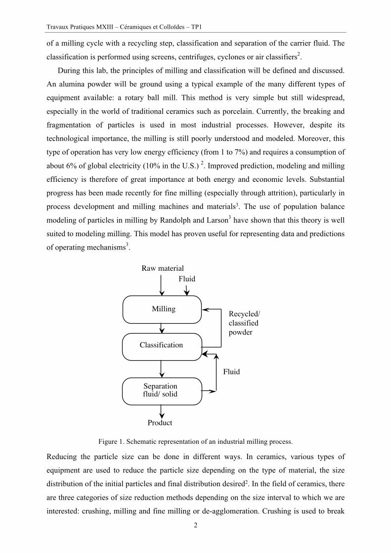
classification equipment enabling the recycling of coarse materials. Figure 1 shows a diagram
Travaux Pratiques MXIII – Céramiques et Colloïdes – TP1
2
of a milling cycle with a recycling step, classification and separation of the carrier fluid. The
classification is performed using screens, centrifuges, cyclones or air classifiers2.
During this lab, the principles of milling and classification will be defined and discussed.
An alumina powder will be ground using a typical example of the many different types of
equipment available: a rotary ball mill. This method is very simple but still widespread,
especially in the world of traditional ceramics such as porcelain. Currently, the breaking and
fragmentation of particles is used in most industrial processes. However, despite its
technological importance, the milling is still poorly understood and modeled. Moreover, this
type of operation has very low energy efficiency (from 1 to 7%) and requires a consumption of
about 6% of global electricity (10% in the U.S.) 2. Improved prediction, modeling and milling
efficiency is therefore of great importance at both energy and economic levels. Substantial
progress has been made recently for fine milling (especially through attrition), particularly in
process development and milling machines and materials3. The use of population balance
modeling of particles in milling by Randolph and Larson3 have shown that this theory is well
suited to modeling milling. This model has proven useful for representing data and predictions
of operating mechanisms3.
Figure 1. Schematic representation of an industrial milling process.
Reducing the particle size can be done in different ways. In ceramics, various types of
equipment are used to reduce the particle size depending on the type of material, the size
distribution of the initial particles and final distribution desired2. In the field of ceramics, there
are three categories of size reduction methods depending on the size interval to which we are
interested: crushing, milling and fine milling or de-agglomeration. Crushing is used to break
Milling
Classification
Raw materialFluid
Fluid
Recycled/ classified powder
Separation fluid/ solid
Product

Travaux Pratiques MXIII – Céramiques et Colloïdes – TP1
3
large pieces of minerals (m) into smaller pieces whose size is adapted to milling (from cm to
mm). The milling is applied to input particle size ranges from mm to several hundred microns
and reduces the size to values between 1 and 50 µm (ball mill). Finally, fine milling reduces
particles to submicron sizes, typically between 0.1 and 1 micron in diameter (vibratory mills,
jet mills and attrition mills). A major drawback of ceramic powders milling is the contamination
of ground powders due to wear of milling media (beads, pots, stirrers). The material used in the
manufacture of milling media is selected according to the powders to be ground, but also of its
mechanical properties (hardness and tenacity) and will depend on the effect of contamination
on the sample to be ground.
2.1. Practical points
Milling of a coarse alumina; the key factors to be examined are: choice of the jar, beads, powder
load and rotation speed.
i) Principles of operation
This section will present the rules for good practice in the rotary ball milling of ceramic powders
using beads. The proposed rules below are a guide to maximize the efficiency of the ball milling
process, that is to say, to obtain the desired particle fineness in a short time (hence minimal
energy consumed), with minimum wear of the jar and milling beads (thus minimal
contamination of the ground powder) 4. Rotary ball milling loads a jar with the sample to be
ground and the beads andis set to rotate around its axis at a certain speed. The rotation of the
jar is usually done with a roller machine (Figure 2). The sample may be ground in dry form or
dispersed in a suitable solvent (e.g. in water or in alcohol). The dispersion may also contain
certain additives (such as a dispersant or anti-foaming agent).
ii) Rotation speed
For the inside jar diameter Di, there is a critical rotation speed above which the contents of the
container remain held on the wall under the effect of the centrifugal acceleration. This critical
speed is given by equation [1].
ω$ = 42.3𝐷,
where ω$ is the critical rotation speed (rpm)
Di is the inner diameter of the milling jar (m) [1]

Travaux Pratiques MXIII – Céramiques et Colloïdes – TP1
4
Process parameters - The volume of the jar - The inner and outer diameters of the jar - The total volume of milling beads - The diameter(s) of the milling beads - The volume of material to be milled - The speed of rotation of the jar - The duration of milling - Dr: diameter of the roller (m) - ω-: rotational speed of the roller (rpm) - De: outer diameter of the milling jar (m) - Di: inner diameter of the jar (m) - ω.: rotational speed of the jar (rpm)
Figure 2. Operating principles of the rotary ball mill. To optimize the milling, it is recommended to use a rotation speed of about 60-65% of the
critical speed. This velocity is called the nominal rotational speed, ω/ (ω/ = 0.60ω$), given in
equation [2].
ω/ = 25.4𝐷,
[2]
If the dimensions of the jar and the rollers are known, the rotational speed of the drive roller,
ω-, can be determined using the equation [3].
ω- = 25.4𝐷1𝐷2 ∙ 𝐷,
[3]
The diameters are in meters and the speed of rotation in turns per minute. In the case of a jar
with a relatively thin wall (De @ Di), equation [3] is reduced to:
ω- = 25.4 𝐷1
𝐷2
[4]
iii) Selection of milling beads
To minimize contamination, we must choose a jar and beads made of a material with high
tenacity and if possible harder than the sample to be milled. Alumina and stabilized zirconia
(much more expensive) are commonly used in the manufacture of jar and beads. The average
diameter of milling beads must be adapted to the size of the particles to be ground. The finer
the particles are, the smaller the diameter of the beads needs to be. For a common ceramic
powder, ball diameter chosen will be about a centimeter. The milling efficiency is maximized
by using a mixture of beads of three different diameters (e.g. 20,10 and 5mm). The ratio of the
+
Dr
Di
De
+ +wr
wj

Travaux Pratiques MXIII – Céramiques et Colloïdes – TP1
5
diameters of the beads is 1:2:4. The total volume of beads, including pores, will be
approximately 50-60% of the volume inside the jar. The beads of different sizes are distributed
in the following proportions, expressed in weight percentage: 25% small, 50% medium and
25% large.
iv) Volume of material to be ground
To reduce wear on the bearings, the load must completely cover the milling ball charge (i.e. the
powder to be milled). In general, it will represent a volume corresponding to approximately
25% of the volume of the jar. If the load to be ground is a dry powder, the beads volume can be
adjusted after a few minutes of milling or vibration. Milling reduces the particle size and the
volume of pores between particles. It is necessary to periodically check if the volume of powder
is sufficient to cover all the beads. If this is not the case, it is necessary to remove the excess
beads to minimize contamination of the powder. After calculating the parameters of milling,
the alumina powder to be ground, the jar and beads will be weighed. Then milling is carried out
for 2 hours. At the end of milling, the powder will be recovered and its size characterized using
the laser diffraction particle size analyzer. Finally, the jar and beads will be cleaned and
weighed to determine the weight loss to monitor the wear rate during milling.
2.2. To do list
§ Materials needed
- Alumina powder
- Milling jar, milling beads, roller machine
- Results of size distributions (before and after milling)
- Mortar mill, balance accurate to 0.01g, spatulas, shovels
- Surfactant solutions ready (1of demineralized water wash bottle and Isopropyl alcohol)
§ Procedure
- Presentation of milling results
- Discussion of the effects of milling on the size distribution
- Is it good for the production of alumina ceramics of high quality with very good
mechanical properties?
- How can we improve the quality of the milling product?
- Were the wear of the pot and milling beads acceptable?
§ Report (Results)
- Distributions of size before and after milling
§ Report (Discussion of results)
- Choice of mill

Travaux Pratiques MXIII – Céramiques et Colloïdes – TP1
6
- Choice of parameters and material for ball milling
- Effect of milling on the size and size distribution - possible improvements
3. Classification
The classification is the separation of particles into two or more coarse and fine powder
fractions. Classification should not be confused with the process of solid-liquid separation,
where sieves or filters are used to recover particles from a suspension. Classification is usually
done by size but can also depend on other particle properties such as their density, shape,
electrical, magnetic or surface properties. Usually, the classification of particles is done in a
carrier fluid: a liquid or a gas. Most classification equipment by size, operate in size ranges
from 1000 to 0.1 microns; taking advantage of one or more of the following forces: gravitation,
drag forces, centrifugal forces or collisions. The most widely used techniques are sieving and
air classification 1, 2.
The classification technique used in this practical work is sieving2. It allows the separation
of particles down to around 30 microns for dry powders and down to 5 microns in the wet state
(e.g. classification in air vs. classification in suspension). The particle separation is done by
size, using grids, perforated plates or metallic wire meshes. Different wire mesh fabrics are
available. The plain fabric gives often a better sieving performance and is easier to clean than
the crossed wire meshes. In the ceramics industry sieving is generally carried out in water such
that the benefits of plain fabrics have little interest and crossed wire meshes are preferred
because they last longer and are more economic.
Sieving is a simple technique, but improper user protocols lead to errors that are detrimental
to the efficiency and quality of the sieving result. For instance, clogging or blocking of the mesh
by the grains reduces the efficiency (e.g. increases required sieving time) and deformation of
the wire meshes — distorting the dimensions of openings, especially for fine meshes — reduces
the selectivity of a wire mesh. Therefore, the sieve quality (and usage) have to be characterized
by parameters such as (1) the selectivity, (2) recovery, (3) the efficiency/yield and (4) the
sharpness index1.3. These parameters can depend on the powder, the sieve state and the used
protocol. For example, clogging of the wire mesh increases the required time of sieving to
achieve the theoretical selectivity of the used wire mesh.
In this practical work, sieving will be used to classify an atomized ceramic powder and to
calculate the characteristic parameters of the sieve and the sieving protocol.
3.1. Practical points
Sieving will be used to classify an atomized (granulated) ceramic powder. A spray dried powder
with a size distribution from about 35 to 100 µm will be classified into two fractions by sieving.
Travaux Pratiques MXIII – Céramiques et Colloïdes – TP1
7
The size distribution of the two fractions (< 50 and > 50 µm) will be measured using the laser
diffraction method and with the obtained information a selectivity curve will be drawn. The
sharpness index and the recovery will be calculated.
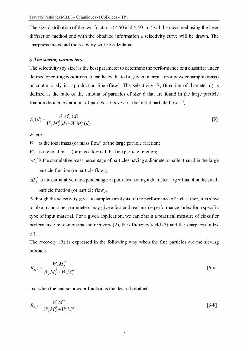
i) The sieving parameters
The selectivity (by size) is the best parameter to determine the performance of a classifier under
defined operating conditions. It can be evaluated at given intervals on a powder sample (mass)
or continuously in a production line (flow). The selectivity, Sc (function of diameter d) is
defined as the ratio of the amount of particles of size d that are found in the large particle
fraction divided by amount of particles of size d in the initial particle flow 1, 3.
( )( )( ) ( )
dc c
c d df f c c
W M dS dW M d W M d
=+
[5]
where:
Wc is the total mass (or mass flow) of the large particle fraction;
Wf is the total mass (or mass flow) of the fine particle fraction; dcM is the cumulative mass percentage of particles having a diameter smaller than d in the large
particle fraction (or particle flow); dfM is the cumulative mass percentage of particles having a diameter larger than d in the small
particle fraction (or particle flow).
Although the selectivity gives a complete analysis of the performance of a classifier, it is slow
to obtain and other parameters may give a fast and reasonable performance index for a specific
type of input material. For a given application, we can obtain a practical measure of classifier
performance by computing the recovery (2), the efficiency/yield (3) and the sharpness index
(4).
The recovery (R) is expressed in the following way when the fine particles are the sieving
product:
,
df f
d f d df f c c
W MR
W M W M=
+ [6-a]
and when the coarse powder fraction is the desired product:
,
dc c
d f d df f c c
W MRW M W M
=+
[6-b]

Travaux Pratiques MXIII – Céramiques et Colloïdes – TP1
8
The difference between the recovery of fine particles and large particles, may be defined as the
efficiency of the classifier, E = Rd,f - Rd,c. A perfect classifier would be able to send all particles
larger than a size limit in the current of large particles, and any smaller particles in the current
of fine particles. This assumes that the size is the only characteristic that influences particle
trajectory. Other features, such as density and shape may also affect the forces acting on the
particles, which influence the effectiveness of classification. On the other hand, the yield is a
measure of the product obtained, regardless of its quality, and is calculated in terms of a fraction
of the input current when the stream of the fine particles is the product:
ff
f c
WY
W W=
+ [7-a]
and when the stream of coarse particles is the desired product:
cc
f c
WYW W
=+
[7-b]
A measure of the slope of the probability function to the diameter Sd50 is the sharpness index,
that is to say, the ratio of the particle size with a 25% probability to go into the stream of large
particles and the particles with a probability of 75% to go into the same outlet.
25
75
SdsSd
= [8]
3.2. To do list
§ Materials needed
- Sprayed dried zirconia powder (Tosoh TZ-3YB)
- Beakers
- Sieve of 50 microns
- Precision balance (0.01g)
§ Procedure
- Classify 10 g of atomized powder with a size distribution of about 35 to 100 microns in
two fractions by sieving.
- The size distributions of two sieve fractions < 50 and > 50 microns will be measured
(Malvern Mastersizer, laser diffraction).
§ Report (Results)
- Report results and indicate the precision
o Sieve recovery
o Results of size distributions

Travaux Pratiques MXIII – Céramiques et Colloïdes – TP1
9
- Draw a selectivity curve (for 10 values of d) and calculate the sharpness index, recovery
and yield to 50 microns (coarse fraction)
§ Report (Discussion of results)
- Choice of method
- Selectivity curve and classification parameters
- Why is the selectivity not perfect? Discuss the advantages and limitations of a sieve as a
classifier
- Discuss the limitations and benefits of a screen as a classifier
- The particle size distribution of the zirconia powder before sieving can be found in the
appendix. Compare it to the results you have obtained for this powder, after sieving.
4. Spray Drying
Spray drying transforms a suspension into powder by evaporation of a dispersive liquid in a
warm and dry environment 5.To do this, the suspension is mixed with a stream of high velocity
gas through an orifice, and then the mixture is dispersed into a large number of droplets. These
droplets are contacted with a hot gas (air) and quickly take a spherical shape because of surface
tension. The droplet size varies between 20 and 500µm depending on the device used. Their
large surface area allows rapid evaporation of the liquid phase in contact with hot gas to give
granules. The characteristics of these granules may be influenced by spray drying conditions
such as temperature, gas flow, or the flow rate of suspension. Knowing these parameters, the
droplet size can be calculated 6.
The spray drying method preserves the homogeneity of a powder mixture in the granule, as
in the case of porcelain (mixture of quartz, feldspar and clay). Spray drying is also the primary
method for adding processing additives such as a binder (e.g. polyvinyl alcohol, PVA),
plasticizers (e.g. polyethylene glycol, PEG) and lubricants (e.g. oleic acid) to the ceramic
powders for dry pressing. The addition of binders is very important for increasing the
mechanical strength during handling and machining of green bodies. Plasticizers facilitate
granule deformation during dry pressing, the granules are somewhat brittle with the binder
alone. The lubricant plays a role during deformation and rearrangement in the compaction of
granules but also reduces friction with the mould walls.
Moreover, the granules prepared by spray drying present better flowability than untreated
powder. This is an important characteristic for the automation of the dry pressing process, as
often encountered in industry. However, the flowability of a powder is often difficult to define
and measure because of its sensitivity to several factors such as size, the nature of the particles
(ceramic or metallic), shape of the apparatus used, and moisture of the powder 7. Several
different methods can be used: angle of repose, slip angle, angle of spatula and free flow time7.

Travaux Pratiques MXIII – Céramiques et Colloïdes – TP1
10
In this practical session, the flowability of the powders prepared by spray drying will be
measured and compared to the commercial powders using a modified Hall flowmeter. This
method involves pouring the powder through a cone and then measuring the amount of powder
required to fill a container of given volume. It is a method that measures the bulk density.
Another density which is often used to characterize a powder is the “tap density”, that is to say,
the density obtained after the powder is vibrated or packed in a certain way.
The ratio of tap density to apparent density (free flow) is called the Hausner ratio. This ratio
is interesting for the characterization of powders for several reasons: it is sensitive to the
flowability, the ease of being compacted, friction of the powders, the particle shapes and sizes.
It increases as the particle size decreases. Moreover, it is almost independent of humidity when
the two densities may vary themselves with significant amounts of moisture.
4.1. Practical points
We will spray dry a powder of submicron alumina (AA04) with different types and amounts of
additives such as dispersant, binder and plasticizer. First, we will prepare a suspension of our
alumina powder designed to be dried by spray drying. After drying, the obtained powder will
be compared with a commercial spray dried powder. Measurements made on these two types
of powders are size, apparent density and tapped density followed by a calculation of the
Hausner ratio related to the flowability of the granules.
i) Preparation of the suspension for spray drying
Weight 80 g powder (Al2O3). Add the powder to a solution of HNO3 (45 g of 0.005 M) Mix
this suspension with a magnetic stirrer for 5 min to wet the powder and then treat it 5 min with
the ultrasonic horn (140 W, 20 KHz) to break the agglomerates (always stirring). Then add the
polyvinyl alcohol solution (aqueous) (15g of a solution of 1.5% weight) and the solution of
polyethylene glycol (PEG, Mw 3350, 10 g of a solution of 2% weight). Then treat the
suspension for 5 min with the ultrasonic horn (140 W, 20 KHz). Finally move to ultrasonic bath
(protected with parafilm) for degassing (5 minutes).
ii) Getting Started with the Spray dryer (Figure 3)
The parameters for the flow of cooling water (about 1l/min), the gas flow (500 on the flow
meter), the temperature (15 min to give 220 ° C at the inlet and 120 ° C at the outlet), vacuum
(maximum) are explained during the practical course. The heating takes about 15 minutes.
During this period, the suspension for spray drying is treated with ultrasonic horn etc. Check
that the atomizer is working properly by passing 10 ml of water with the peristaltic pump to the
atomizer. The prepared suspension is atomized with a given flow rate and the pump is stopped

Travaux Pratiques MXIII – Céramiques et Colloïdes – TP1
11
when the outlet temperature reaches 110 °C (about 5 ml of water is used to purge inlet pipes
before the pump is stopped). It takes about 5 minutes for the outlet temperature to warm up to
128-130 °C. When the whole suspension is atomized, the heater and pump are stopped and the
spray is allowed to cool to 35 °C (~ 30 min). The sample is collected and weighed. The portion
of particles too large which fall directly into a collector without going through the cyclone are
also collected.
Operating principle The Mini Spray Dryer BUCHI operates on the principle of nozzle atomization in parallel flow. That is to say that the atomized product and drying air flow in the same direction.2
Diagram of the flow of air 1. Suction port 2. Heating 3. Entry of stabilized flow into drying
chamber 4. Cyclone. The product is here separated
from the air flow 5. Aspiration device 6. Temperature measurement of the inlet air.
This temperature can be adjusted as needed.
7. Temperature measurement of the air at the outlet. The optimal choice of the temperature difference between the input and the output is one of the important points of the drying operation. The outlet temperature cannot be arbitrarily adjusted, it results from the combination between the inlet temperature, the suction and the pump flow controls.
8. Product collection container.
iii) Tap density and flowability measurements
Tap density measurements are made with the Hall flowmeter with an extension (the same
container is used for the flowability with the Hall flowmeter). The flowability is assumed to be
inversely proportional to the apparent volume. The powder sample (about 40 g) is poured
through the cone to fill the container and “tapped” to pack the powder by dropping the contains
from a height of 15 mm for 20 times. The extension is removed and excess powder that goes
beyond the edges of the container is removed with a straight piece without producing any
vibration to the surface. The remaining powder in the container is weighed and the tap density
is calculated (the volume of the container is 25 cm3). The test is done twice with the commercial
powder and twice with a spray dried powder from a previous lab session. The two powders are
recovered and stored for later use.

Travaux Pratiques MXIII – Céramiques et Colloïdes – TP1
12
A: Suspension B: Feed pump C: product channel D: Input for compressed air E: Input for cooling water F: The nuzzle
Figure 3. Schematic diagrams of the spray dryer.
4.2. To do list
§ Materials needed
- Powders for flowability: non-atomized alumina and atomized commercial alumina
- Plastic containers (250 ml)
- Acid polyvinyl alcohol (PVA), polyethylene glycol (PEG), HNO3 (solutions)
- Büchi Atomizer "Lab Spray Dryer"
- 50 ml glass beakers (2x), 100 ml (2x), 250 ml (2x)
- An ultrasonic probe
- Magnetic stirrer and bar
- Modified Hall Flowmeter
- Powder Scoops, 250 ml graduated cylinder
- Spatulas, precision balance 0.01 g
§ Report (Results)
- Yield on Spray drying, and vibrated apparent densities, Hausner ratio
- Calculate the% wt of PEG and PVA in the granules compared to the dry powder § Report (Discussion of results)
- Size distribution of primary particles and granules, shape of granules
- Comparison of the Hausner ratio and flowability for the two types of powders
(commercial and TP)
5. Granulometry The particle size analysis method differs depending on the size of particles to be studied. For
ceramic powders at LTP, four methods are generally used: a) laser diffraction for powders with
a size between 100 nm and 1 mm, b) centrifugal sedimentation for powders with a size between
Travaux Pratiques MXIII – Céramiques et Colloïdes – TP1
13
10 nm and 300 microns, c) photon correlation spectroscopy for powders ranging in size from 2
nm and 500 nm and d) image analysis - for all sizes but of particular interest for non-spherical
particles.
The purpose of this practical course is an introduction to the most versatile and widely used
method namely the static light scattering method known as laser diffraction. The other methods
are described in detail in the Ceramic and colloids Processing course or can be found in the
literature 2, 8,9.
5.1. Practical points
i) Distributions and average diameters
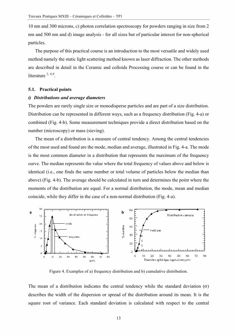
The powders are rarely single size or monodisperse particles and are part of a size distribution.
Distribution can be represented in different ways, such as a frequency distribution (Fig. 4-a) or
combined (Fig. 4-b). Some measurement techniques provide a direct distribution based on the
number (microscopy) or mass (sieving).
The mean of a distribution is a measure of central tendency. Among the central tendencies
of the most used and found are the mode, median and average, illustrated in Fig. 4-a. The mode
is the most common diameter in a distribution that represents the maximum of the frequency
curve. The median represents the value where the total frequency of values above and below is
identical (i.e., one finds the same number or total volume of particles below the median than
above) (Fig. 4-b). The average should be calculated in turn and determines the point where the
moments of the distribution are equal. For a normal distribution, the mode, mean and median
coincide, while they differ in the case of a non-normal distribution (Fig. 4-a).
Figure 4. Examples of a) frequency distribution and b) cumulative distribution.
The mean of a distribution indicates the central tendency while the standard deviation (s)
describes the width of the dispersion or spread of the distribution around its mean. It is the
square root of variance. Each standard deviation is calculated with respect to the central
a b

Travaux Pratiques MXIII – Céramiques et Colloïdes – TP1
14
tendency used, which in the case of the formula of equation 9, is dv, the volume average
diameter.
2( )i i vv
f d dV
sæ ö-
= ç ÷è ø
å [9]
where f is the frequency of particles (by volume) and V is the total volume for all intervals of
the diameter.
Distributions can often be represented by mathematical expressions that describe the entire
distribution from two parameters: the central tendency (mean) and standard deviation.
Reference 1 presents a thorough measurement of different distributions of particle size (Normal,
log-normal, Rosin-Rammler). Table 1. Some examples of different mean diameters and their mathematical representation. i = class of particles, Ni = number or percentage of particles in class i, SBET = specific surface area [m2/g] and r = density of the powder [g/cm3].
Diameter Definition Diameter Definition
Number - length dnl =di Ni
i=1
n
å
Nii=1
n
å
Volume - moment
(Weight - moment)
4
1
3
1
n
i ii
v nm
i ii
d Nd
d N
=
=
=å
å
Number - volume dnv =di3Ni
i=1
n
å
Nii=1
n
å3 Specific Surface
Area
dBET =6
SBET × r(µm)
𝑆𝑆𝐴 = 6𝜌 .
𝑛,𝑑,:
𝑛,𝑑,;
ii) Method – laser diffraction
A schematic representation of the laser diffraction method is presented in Figure 5. Laser
diffraction can measure powders from 3000 µm to about 0.1 µm.2,7,8 The main limitations
appear when particles are non-spherical, and when the optical properties of materials are not
available.

Travaux Pratiques MXIII – Céramiques et Colloïdes – TP1
15
Figure 5. Schematic representation of laser diffraction method for particle size measurement.
Laser diffraction analyzers can be used with suspensions and dry powders. The diffraction
pattern is a superposition of the pattern of each particle size in powder analyzed. In the data
analysis, an initial size distribution is "estimated" and a theoretical diffraction pattern is
calculated and compared with experimental data. The differences between the "estimated" and
"experimental" data are then minimized using the method of least squares. The residue resulting
from the difference gives a guide to the validity of the model used to represent data. The
software then calculates the volume distribution as a fundamental result and other information
is deduced from this result by assuming that the particles have a spherical shape.
Several studies using this type of instrument with various particules 7, 8 show very good
results for particle sizes > 1 µm. For spherical particles, the results are accurate and
reproducible, making this instrument a good tool for granulated powders. The results with
quartz powder standard, irregular geometry, in the range of 0.3 - 200 µm, are less accurate but
still very reproducible 7, 10. The method is very popular because of its high speed; the analysis
only takes a few minutes. Again, the main limitations of this type of instrument appear when 1)
the particles analyzed are smaller than 1 µm (Mie theory must be used), 2) in the presence of
non-spherical particles or 3) the difference between the refractive index of the solvent and the
powder is low (e.g. polymeric materials).
5.2. To do list § Procedure
- Measurement of particle sizes distributions of alumina powder before and after milling
- Analysis of granulometry of spray dried powders from both a commercial source and
from the laboratory spray dryer.
Lense Sample
Laser Light
Detector
Computer

Travaux Pratiques MXIII – Céramiques et Colloïdes – TP1
16
6. Report § Brief Introduction
- Brief description of experimental details - Do not repeat the script of TP, a brief description of experiments and equipment
used and any special comment on certain points if necessary § Results
Milling - Distributions of size before and after milling
Classification - Report results and indicate the precision - Draw a selectivity curve (for 10 values of d) and calculate the sharpness index,
recovery and yield to 50 microns (coarse fraction) Spray drying
- Yield on Spray drying, and vibrated apparent densities, Hausner ratio - Calculate the% wt of PEG and PVA in the granules compared to the dry powder
§ Discussion of Results
Milling - Choice of mill - Choice of parameters and material for ball milling - Effect of milling on the size and size distribution - possible improvements
Classification - Choice of method - Selectivity curve and classification parameters - Why is the selectivity not perfect? Discuss the advantages and limitations of a sieve
as a classifier Spray drying
- Size distribution of primary particles and granules, shape of granules - Comparison of the Hausner ratio and flowability for the two types of powders
(commercial and TP)
§ Conclusions ---------------------------------------------------------------------------------------------------------------------------
Approximate Timing Section Total Milling – Weighing and launch 30 min 30 min Preparation of the suspension of alumina and heating Atomizer 30 min 1h Spray drying 30 min 1h30 Measures of apparent density and tapped density 1h 2h30 Sieving (Strain 10 g of atomized powder included) 15 min 2h45 Recovery milling 15 mins 3h Particle size measurements and cleaning 30 mins 3h30 Discussion of result 30 mins 4h

Travaux Pratiques MXIII – Céramiques et Colloïdes – TP1
17
Annexes
Transformation-Toughened Zirconia (TTZ)
Transformation-toughened zirconium oxide (TTZ) is another important high-strength, high
toughness ceramic that has been developed during the past 20–25 years. Transformation
toughening was a breakthrough in achieving high-strength, high toughness ceramic materials.
For the first time in history a ceramic material was available with an internal mechanism for
actually inhibiting crack propagation.
Transformation toughening requires a bit of explanation. It is one of those properties that
involves control of composition and manipulation of microstructure. Zirconia is a material that
undergoes a change in the way its atoms are stacked at different temperatures (polymorphic
transformation). Zirconia has the monoclinic crystal structure between room temperature and
about 950 ℃. Above 950 ℃ zirconia converts to the tetragonal crystal structure. This
transformation is accompanied by larger than one percent shrinkage during heating and
equivalent expansion during cooling. At a much higher temperature, the zirconia changes from
tetragonal to a cubic structure.
With proper chemical additions and heat treatments, a microstructure can be achieved
during cooling that consists of lens-shaped “precipitates” of tetragonal zirconia in cubic grains
of zirconia, as shown in Fig. 2-16. Normally, the tetragonal material would transform to the
monoclinic form during cooling, but it must expand to do so. The high strength of the
surrounding cubic zirconia prevents this expansion, so the tetragonal form is retained all the
way down to room temperature. As a result, each tetragonal zirconia precipitate is under stress
and full of energy that wants to be released, sort of like a balloon that has been stuffed into a
box that is too small. As soon as the box is opened, the balloon is allowed to expand to its
equilibrium condition and protrude from the box. The same thing happens for each tetragonal
precipitate if a crack tries to form or if someone tries to break the ceramic. The crack is
analogous to opening the box. Tetragonal precipitates next to the crack are now able to expand
and transform back to their stable monoclinic form. This expansion adjacent to the crack,
presses against the crack and stops it. This is the mechanism of transformation toughening. It
is similar to the toughening mechanism in some forms of steel, so the TTZ has sometimes been
called “ceramic steel.” TTZ has been developed in a couple of different forms. The one
described above is typically called partially stabilized zirconia (PSZ). The second form consists
of nearly every crystallite or grain in the material being retained in the tetragonal form to room
temperature so that each grain can transform instead of only the precipitates. This material is
referred to as tetragonal zirconia polycrystal (TZP). Both types are mentioned because they
have different properties, and one may be preferable for a specific application.

Travaux Pratiques MXIII – Céramiques et Colloïdes – TP1
18
A crack, in a normal ceramic, travels all the way through the ceramic with little inhibition,
resulting in immediate brittle fracture. TTZ has fracture toughness (resistance to crack
propagation) 3–6 times higher than normal zirconia and most other ceramics. It is tougher than
cast iron and comparable in toughness to WC-Co cermet. TTZ is so tough that it can be struck
with a hammer or even fabricated into a hammer for driving nails. Figure 2-15 displays
examples of TTZ tooling for fabrication of aluminium cans. For a part such as an extrusion die,
TTZ typically costs around four times as much as steel and two times as much as WC-Co. The
suppliers can provide information on life-cycle cost for existing applications and can probably
estimate for similar applications.

Travaux Pratiques MXIII – Céramiques et Colloïdes – TP1
19
Particle size distribution of the zirconia powder before sieving

Travaux Pratiques MXIII – Céramiques et Colloïdes – TP1
20
AA04 Powder characteristics
A high purity α-Al2O3 (Sumitomo AA04, batch YD9812, Solvadis Chemag GmbH, Germany); the total impurity concentration is less than 0.01 mass% (≤ 5 ppm for Si, Na, Mg, Cu and Fe)
PSD Dv10 = 240nm Dv50 = 550 nm Dv90 = 1180 nm SSA = 4.2 m2/g Isoelectric point ( iep) pH = 9.86 (NaCl 0.01M)
(a) SEM image and (b) TEM image of the AA04 a-Al2O3 powder.
Cum
. Fre
q. [%
]
Freq
. [%
]
Size [μm]
Freq. Cum. Freq
Travaux Pratiques MXIII – Céramiques et Colloïdes – TP1
21
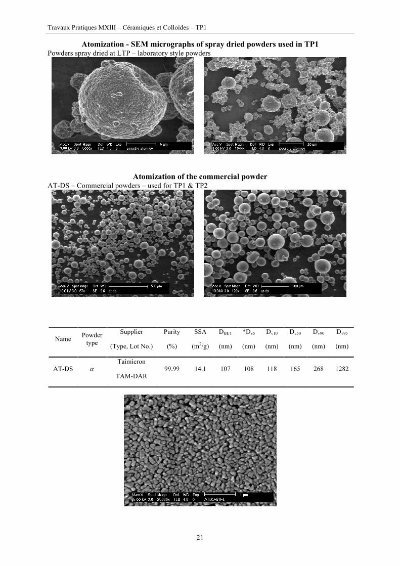
Atomization - SEM micrographs of spray dried powders used in TP1 Powders spray dried at LTP – laboratory style powders
Atomization of the commercial powder AT-DS – Commercial powders – used for TP1 & TP2
Name Powder type
Supplier
(Type, Lot No.)
Purity
(%)
SSA
(m2/g)
DBET
(nm)
*Dv5
(nm)
Dv10
(nm)
Dv50
(nm)
Dv90
(nm)
Dv95
(nm)
AT-DS 𝛼 Taimicron
TAM-DAR 99.99 14.1 107 108 118 165 268 1282
Travaux Pratiques MXIII – Céramiques et Colloïdes – TP1
22
Bibliography
1 J.S. REED, "Introduction to the Principles of Ceramic Processing" 2nd Edition, J. Wiley, NY, 1995. 2 J. Barton, P. Bowen, C. Carry and J.M. Haussonne. Traité des Matériaux, Volume 16, Céramiques et Verres : Principes et techniques d’élaboration, ISBN 2-88074-605-1, Presses Polytechniques et Universitaires Romandes, 2005. 3 (a) A.D. Randolph and M.A. Larson,"Theory of Particulate Processes", 2nd Edition, Academic Press, NY, 1988. (b) J. A. Dodds, C. Frances, P. Guigon, A. Thomas "Méthodologies pour la Modélisation du Broyage Fin", Colloque sur Science et Technologie des Poudres, Lyon, France, Novembre 1994. 4 T. Docktor ,P. Weymouth & T. Barson , "Proper Techniques for the Ball-Milling of Ceramic Glazes." Amer. Ceram. Soc. Bull. 73(1) 54-58 (1994). 5 S.J. Lukasiewicz, "Spray-Drying Ceramic Powders" J. Am. Ceram. Soc., 72(4) 617-24 (1989). 6 D. Kumar, R. Ladisch, E. Lutz et N. Claussen, "Powder Preparation via Spray Dryer", Ceram. Forum Int., 5 (1988)141-44. 7 L. Svarovsky, "Powder Testing Guide: Methods of Measuring the Physical Properties of Bulk Powders", Elsevier Applied Science, London, 1987. 8 Bowen, P. “Particle Size Distribution Measurement From Millimeters to Nanometers and From Rods to Platelets”, J. Dispersion Science and Technology, 23(5) 631-662 (2002). 9 Aimable, P. Bowen, “Ceramic Nanopowder Metrology and Nanoparticle size measurement - towards the development and testing of protocols” J. Processing and Application of Ceramics, 4[3] 147-156 (2010) 10 R. Xu et al– Paper 41- «Particle size and shape analysis using light scattering, coulter principle, and image analysis»World Congress Particle Technology, Sydney, 2002.