towing-tank tests on a large six-engine flying boat...
TRANSCRIPT

..
MINISTRY OF SUPPLY
AERONAUTICAL RESEARCH COUNCIL
REPORTS AND MEMORANDA
R. & M. No. 2834 (13,9e~)
A.R.~. Technical Re~oz~
-a
4) set !9S¢
i :L i
Towing-Tank Tests on a Large Six-Engine Flying Boat Seaplane,
to Specification io/46 (Princess) PART II
Porpoising Stability, Spray and Air Drag Tests, with Improved Step Fairing, Afterbody Design and
Aerodynamic Modifications
A. G. SMITH, B.Sc., D.I.C., D. F. WRIGHT A N D T. B. OWEN, M.A.
Crown Copyright Reserved
L O N D O N : H E R M A J E S T Y ' S S T A T I O N E R Y O F F I C E
I954
VRICE. 8S 6d NZT

Towing-Tank Tests on a Large Seaplane, to Specification
Six-engine Flying Boat o/46 (Princess)
PART II* Porpoising Stability, Spray and Air Drag Tests, with Improved Step Fairing,
Afterbody Design and Aerodynamic Modifications
A. G. SMITH, B.Sc., D.I.C., D. F. WRIGHT and T. B. OW~N, M.A.
COMMUNICATED BY THE PRINCIPAL DIRECTOR OF SCIENTIFIC RESEARCH (AIR), MINISTRY OF SUPPLY
Reports ,2~d Memora#d~ No.
November, 19 5 o
2 8 3 4"*
. . . . . . . . . . . . . . . . 5:= i"
v ~ 7,-7:-. ~,",'r-,.,%;:,!~%~i::~k~[:£{t [!,,,,-'J , ' ,J "~ t-
Summary. Introductory.--Further model tests were made on the Princess flying boat to : - - (a) improve the main-step fairing in order to reduce air drag while retaining satisfactory porpoising stability at
high water speeds, (b) reduce the mid-planing porpoising instability found with the hull lines tested in Part I of this report (R. & M.
2641), (c) test the effect of increased wing and tailplane areas, (d) predict more accurately the full-scale performance of the final hull form by representing more closely the
anticipated full-scale conditions of lift, slipstream and damping in pitch.
The tank tests were made in sheltered water conditions in the Seaplane Towing Tank, Royal Aircraft Establishment, Farnborough, oil a dynamic model, and parallel tunnel tests on the step-fairing design were made in the Saro Wind Tunnel at Osborne.
The final hull form evolved is used for the first production aircraft.
Condusions.--(i) The hull air drag has been reduced about 12 per cent, so ttiat the surface-drag coefficient is of the order of 1 .25 times that of the equivalent body of revolution of the same length and maximum cross-sectional area. I t is anticipated that this drag reduction will be achieved full-scMe. By adopting more drastic revision of hull fairings, a total reduction of the order of 25 per cent might be possible, but it was decided that insufficient evidence existed at the time to justify confidence in resulting hydrodynamic performance at high speeds.
(if) There is evidence of skipping instability on the model at high speeds immediately prior to take-off, or following landing, but this is probably the result of blister interference with tile sides of the lower pressure circle aft, and therefore likely to bemuch reduced full-scale. Afterbody clearance from the forebody wake is very good up to at least 340,000 lb for take-off and 280,000 lb for landing.
(iii) The technique devised for better representation of full-scale lift and slipstream proved successful and enabled more accurate prediction to be made of full-scale performace. With the enlarged wing and tailplane the stability and trim on the water are now good by present standards up to at least 340,000 Ib for take-off and 280,000 lb for landing. These weights are 30,000 lb more than predicted from the tests reported in R. & lVi. 26411, and are above the anticipated overload design weights.
* Part I, R. & M. 2 ~ 1 . ** R.A.E. R e p o r t 4 0 4 , received 28th April, 1951.
(6t785)
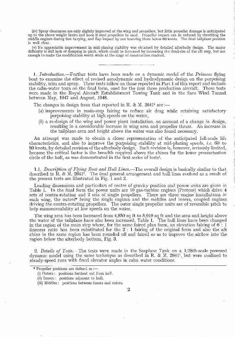
(iv) Spray clearances are only slightly improved at the wing and propellers, but little propeller damage is anticipated up to the above weight limits and none if steel propellers be used. Propeller impact can be reduced by throttling the middle engines during fast taxying, and flap impact by not lowering them below 60 knots. The final tailplane position is well clear.
(v) No appreciable improvement in mid-planing stability was obtained by detailed afterbody design. The major difficulty is still lack of damping in pitch, which could be increased by increasing the dead-rise at the aft step, but not enough to make the modification worth while at the stage of construction reached.
1. !~troductio~.--Further tests have been made on a dynamic model of the Pri~cess flying boat to examine the effect of revised aerodynamic and hydrodynamic design on the porpoising stability, trim and spray. These tests follow on those reported in Part I of this report and include tile calm-water tests on the final form, used for the first three production aircraft. These tests were made in the Royal Aircraft Establishment Towing Tank and in the Saro Wind Tunnel between May, 1947 and August, 1948.
The changes in design from that reported in R. & M. 26411 are : - - (a) improvements in main-step fairing to reduce air drag while retaining satisfactory
porpoising stabili ty at high speeds on the water, (b) a re-design of the wing and power plant installation, on account of a change in design,
resulting in a considerable increase in wing area and propeller thrust. An increase in the tailplane area and height above the water was also found necessary.
An at tempt was made to obtain a closer representation of the anticipated hill-scale lift characteristics, and also to improve the porpoising stabili ty at mid-planing speeds, i.e. 60 to 80 knots, by detailed revision of the afterbody design. Such revision is, however, seriously limited, because the critical factor is the breadth required above the chines for the lower pressurisation circle of the hull, as was demonstrated in the first series of tests 1.
1.1. Descriptio~ of Flyi~¢g Boat a~¢d Hull Li~es.--The overall design is basically similar to that described in R. & M. 26411. The final general arrangement and hull lines evolved as a result of the present tests are illustrated in Fig. 1 and 2.
Leading dimensions and particulars of centre of gravity position and power units are given in Table 1. In the final form the power units are 10 gas-turbine engines (Proteus) which drive 4 sets of contra-rotating and 2 sets of single propellers. There are three engine installations in each wing, tile outers* being thes ing le engines and the middles and inners, coupled engines driving the contra-rotating propellers. The outer single propeller units are of reversible pitch to help manoeuvrabil i ty at low speeds on the water.
The wing area has been increased from 4,850 sq ft to 5,019 sq ft and the area and height above the water of the tailplane have also been increased, Table 1. The hull lines have been changed in the region of the main step where, for the same faired plan form, an elevation fairing of 6 : 1 fineness ratio has been substituted for the 2 : 1 fairing of the original form and also the aft chine in the same region has been rounded off and faired so as to improve the airflow into the region below the afterbody bottom, Fig. 3.
2. Details of Tests.--The tests were made in the Seaplane Tank on a 1/28th-scale powered dynamic model using the same technique as described in R. & ~ . 26411, but were confined to steady-speed runs with fixed elevator angles in calm water conditions.
* Propeller positions are defined as :-- (i) Outers : positions furthest out from hull. (if) Inners : positions adjacent to hull. (iii) Middles : positions between inners and outers.
2

2.1. Hull Modifications.--Tests on the effect of modifications to the main-step fairing and after- body lines on porpoising stability and trim were made first in the model condition, Mod. T, used for the final tests described in R. & M. 26411, but with the larger raised tailplane for the latter half of the tests. The tests were made at all-up weights of 310,000 lb and 340,000 lb with the c.g. at 30 per cent S.M.C. (standard mean chord) with full anticipated take-off thrust but zero wing flaps. The higher all-up weight tested represents a severe over.loading condition due to the original smaller wing being used, but was deliberately chosen so as to amplify any deterioration in the hydrodynamic behaviour caused by the main-step and afterbody modifications.
In parallel with these tank tests, the firm and R.A.E. jointly made comparative tests on a hull in tile firm's wind tunnel, both to explore the nature of the airflow round the step, and to measure the. drag with various degrees of fairings and elimination of the afterbody chine ill the main-step region.
2.2. Wing and Power Plant Modifications.--Following the decision on a final fairing design, a new model was constructed incorporating the increased wing area and propeller thrust as well as the fna l hull form, and the larger tailplane introduced dur ing the fairing modification was retained. Measurements of lift and thrust were made on the model, and wing leading-edge slats were designed and fitted to improve the lift-slope and stalling characteristics. The model was now representative of the three prototype aircraft under construction and, besides comparative tests on the effect of the increased wing area and propeller thrust, a range of weights, c.g. positions and flap angles were covered to assess the final form performance. The test programme covered was as tabulated below.
Condition . All-up
weight Oh)
Flap setting (deg)
C.G. position (per cent S.M.C.)
Take-off
Landing
310,000 0
15 30"2 24"8 30"2
340,000 0 30.2 15 30-2
370,000 0 30.2
220,000 0 45
0 45 250,000
280,000
28"2 28"2
28"2 24 "8 28 "2
28"2
The maximum take-off and landing weights tested are considerably greater than any anticipated overload, but were used to give some systematic data from which the performance characteristics at other weights could be interpolated as required. The spray impact positions were noted and plotted in terms of att i tude and speed, and photographs were also taken from forward at speeds below the hump speed (50 knots), to illustrate spray interference with the propellers.
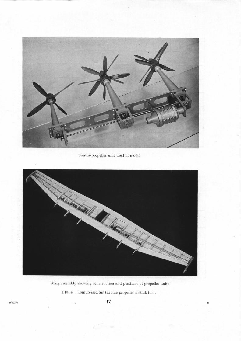
3. Model Wing-Lift and Propeller-Thrust Characteristics.--3.1. Power Units.--The new wing and power-unit installation is illustrated in Fig. 4. I t was decided to make a scale representation of the contra-rotating and single propeller units, so tha t the best representation of full-scale slipstream velocity and twist and their effects could be obtained. The simplest solution available,
3 (61785) A 2

consistent with keeping down the weight for the light load take off test condition, was to use in each wing a four-stage axial-flow turbine" driven by compressed air and to couple this by suitable shaft drive, reduction and bevel gearing to the propellers. These units proved comparatively easy to manufacture and gave very few mechanical difficulties in operation, as well as providing a considerable margin of reserve power.
The four-stage axial-flow-turbine was mounted perpendicular to the chord-line along the position of maximum thickness of the wing. Each complete assembly* was mounted on a stiffened metal base-plate so tha t it formed an independent unit which could be removed for maintenance purposes, and also strengthened the wing. Each unit weighed 11½ oz and the turbine had a maximum power output of about 1.5 h . p . The propellers were made of cedarwood and were equivalent to 17 ft diameter full-scale.
This powered model, when balanced to the correct c.g. position was too heavy to represent the lighter landing conditions, due to the increased weight of the power units compared with the simpler units used in Ref. 1. An additional wing was therefore made, similar in shape to the take- off wing, but which had no power unit or propellers fitted and was provided with full-span leading-edge slats.
3.2. Wi~zg-Sectio~¢ and Lift Measure~ents.--The wing section used on the first dynamic m o d e l 1, i.e., NACA 6418, at the root chord, did not give the anticipated full-scale characteristics of the high-speed section actually used on the aircrafh Both the maximum lift and the lift slope without s]ipstream were much below those obtained in R.A.E. wind-tunnel tests a at a Reynolds number of 7 × 10⁵. The new wings were therefore made with the actual full-scale section and leading-edge slats added. These were beaten out of light alloy sheet to the same contour as the leading edge of the wing. Much better agreement with the anticipated full-scale lift character- istics was obtained. The results of the measurements without slipstream are given in Fig. 5, and with slipstream in Fig. 6.
3.3. Pr@eller Thr,tst.--The estimated full-scale values of propeller and jet thrust are given in Fig. 7. The model thrust was calibrated against the turbine inlet pressure over the take-off speed range and a curve of the pressure required to give the scale propeller thrust deduced. This was then used throughout the tests. A check on the propeller speed showed that it was within 5 per cent of the value scaled down from full-scale, so the rotation as well as the intensity of t h e slipstream should have been correct.
4. Aerodyna~ic and Hydrodynamic Tests o~ Hull-St@ Fairing Desig~¢.--4.1. Air Drag of Modification N Hull Form.--Wind-tunnel tests were made in the Compressed Air Tunnel of the National Physical Laboratory to check the aerodynamic cleanness of hull form Nod. N, Fig. 3 of Ref. 1. The results are plotted in Fig. 8 in the form of drag coefficient per unit surface area against Reynolds number and compared with the results of another series of tests showing what gains might be expected with a classical form of British hull (designated the basic form) by degrees and styles of main-step fairing. The Mod. N hull was disappointing, its aerodynamic cleanness being of the same order as tha t of a normal hull of similar plan fineness ratio with an unfaired V plan-form step, although there was apparently a more favourable scale effect.
Examination of the hull suggested that the high drag might be due to : - - (a) insufficient step fairing in elevation and plan (b) flow across the pronounced flared out chines in the forebody (c) interference at the intersection of the upper and lower pressure circles (d) the forward cabin.
The first was the most probable source of drag, the elevation fairing at the step on Mod. N being about 2 to 11 contrasted with a minimum of 6 to 1 found necessary by tunnel tests to remove most of the step drag (Fig. 8). The water lines in the main-step region also showed major discontinuities (see Fig. 3) because of the earlier decision to retain a sharp afterbody chine almost
* There was one unit in each wing consisting of a turbine with its drive to two sets of contra-rotat ing propellers and one single propeller (Fig. 4).
4

in to the forebody chine ; and a breakaway was to be expected in this chine area, where the air flows round the step to fill the space beneath the afferbody. These deductions were proved to be correct by wind-tunnel drag and tufting tests with various step fairings made in the firm's wind tunnel, Fig. 9.
I t is possible tha t the flared out chines forward do account for an increase of the total hull drag up to 3 per cent of the equivalent body of revolution, but no measurable difference could be found in some unpublished full-scale flight tests made on a Sefford I four-engined flying boat with and without fairing to the flared out chines.
The effect of filling in the intersection of the upper and lower pressure circles of a ' double bubble ' or figure-of-eight hull section was tested in the Royal Aircraft Establishment No. 1, ll½-ft Wind Tunnel, but negligible difference was found at a Reynolds number of 8 × 10 6.
Similarly, wind-tunnel tests show little drag penalty can be expected for the forward cabin position full-scale, when boundary-layer transition is forward.
4.2. Wi~d-Tu~ml Tests to Improve Hull-Step Fairi~g.--Tests on a hull without wings or tail assembly were made in the ' Saro ' Open-Jet Wind Tunnel at 0 deg keel incidence at a Reynolds number of 4.1 × 10⁶ (based on hull length) with various degrees of fairing, retaining the basic plan-form of step. The drag results are given in Fig. 8 where they are superimposed on the results of tests made in the Compressed Air Tunnel at the National Physical Laboratory on a series of step shapes and fairings. Photographs indicating the flow past the step as shown by tuft ing are given in Fig. 9.
The original form, Mod. N, showed possible flow separation both near the keel, where the elevation fairing was only twice the step depth, and near the chines following the water-line discontinuity produced by the forward extension of the afterbody fairing. The R.A.E. fairing, Fig. 9, gave a drag reduction of 14.5 per cent by increasing the step elevation fairing to 8 times the step depth, and rounding the afterbody chine in the main step region. The firm compromised on this and obtained a drag reduction of 10½ per cent using a 6 • 1 step elevatioil fairing, retaining more of the aft chine discontinuity and inserting a shallow cove at the step, Fig. 9.
Further combined R.A.E. and firm's tests in the Saro wind tunnel showed that all signs of breakaway could be eliminated by rounding the sections on the R.A.E. fairing, so as to fill in the fairing aft of the step towards the chines, keeping buttock lines straight to as near the chines as possible to reduce the ' waist ' otherwise found in this region. The first tests (Fig. 9), indicated tha t the problem was to merge good buttock lines at the keel region into good water lines in the
• chine region, so that the air could flow round the hull above the step and down underneath the afterbody. Modifications II and UI on Fig. s show what could be achieved by doing this, the basic f.airing/step depth ratio being 8 : 1 in Mod. n and 10 : 1 in Mod. III . There were no coves m these modifications.
A comparison of the Saro tunnel and Com)ressed Air Tunnel results at a Reynolds number of 4. ! × 106 follows.
Original
R.A.E.
Mod. I
Mod. I I
Mod. II Mod. III
Saro Tunnel Compressed Air Tunnel
Primess Hutl Basic Research Hull
Condition C ~ Condition C s
Fairing Mod. N 2 : 1 at keel
Step fairing Nod. AD 8 : 1 at keel
Saro intermediate fairing ~od. AE 6 : 1 at keel
Straight fMring, 8 : 1 at keel, extended towards chines
Ditto with cove Straight fairing 10" i 'at ke'e'l
extended towards chines
0.00477
0.00406
0.00426
0.00380
0.00386 0-00365
Transverse step, no elevation faking
Faired plan-form step, no elevation fairing
Faked plan-form and elevation main step
Transverse step and straight fairing
Basic streamline shape ..
0.00500
0.00440
0.00408
0.00383
0.00333
5

The absolute values of the Saro measurements were in all cases lower than those of the N.P.L., as demonstrated by the tests on Mod. N in the two tunnels, but the decreases in drag with improvement of step fairing were consistent with the N.P.L. systematic results and consistent with the diagnosis that the high drag of Mod. N was due to the short elevation fairing combined wKh discontinuities near the chines introduced by the forward retention of the aft chine.
4.3. Towir~g-Ta~k Tests o~z Improved Step Fairirags.--The interpretation of the tank tests on the various step fairings is complicated by parallel changes in tailplane size and position, and attempts to reduce afterbody interference at medium and high speeds by detail changes in after- body chine and aft step design. In general, the conclusion is that the use of either the R.A.E. fairing or an improved form of the firm's Mod. 1 fairing had no adverse effect on the stabili ty at medium speeds, but undue filling in of the fairing towards the chines caused interference at high speeds and atti tudes (small draft).
The effect of rounding off the aft chine in the main step region to improve afterbody ventilation and step drag was tried in Mod. U. No deterioration of hydrodynamic performance was found.
The effects of the three basic fairings, (a) 2 : 1 as in Mod. AF (b) 6 : 1 as in Step 1Kod. I, Mod. AE (c) the 8 : 1 R.A.E. fairing, Mod AD
are demonstrated in Fig. 10 for the take-off configuration at 310,000 lb and 0 deg flap. The second is basically the same as tha t tested in the tunnel but with the fairing extended nearer the chines to improve air drag. There was no appreciable change in.stabil i ty between the three configurations though the limited tests at high speed indicated the presence of a skipping porpoise just prior to take-off with the larger tairings, confirmed in later tests. This probably also existed in the Nod. N configuration, but had not been found, occurring as it does within 5 to 10 knots of the flying region.
The comparison of the fairings at the severe overload take-off condition is given in Fig. 11. The 2 : 1 fairing was tested in conjunction with the original tailplane while the 6 : 1 and 8 : 1 fairings were tested with the new tailplane. Allowing for the slight deterioration in stabil i ty with the new tailplane (see section 5.2), there is again no appreciable difference in stabil i ty between the three configurations. The high-speed skipping characteristics were not investigated.
The possibility tha t the extended step fairing was introducing ' sk ipp ing ' at high speeds with increased draft, was investigated by making a series of modifications (Table 2) to the aft chine clearances and the introduction of a shallow cove at the main step.
The cove was introduced to ensure tha t the water flow was broken cleanly away from the hull at the step, but produced no change. Breaker or subsidiary steps were put transversely on the fairing aft of the main step to separate any main blister a t tachment at high speeds and these had the effect of changing the skipping to a gentle pitching motion. Observation, however, showed tha t this change was as likely to be caused by the breaking down of the blister and avoidance of its at tachment to the lower pressure circle above the afterhody, as by preventing at tachment to the fairing. To reduce the at tachment to the lower circle, the afterbody chines were both turned down and flared out to form an abrupt discontinuity across the path of the main blister spray of which the direction was almost parallel to the existing chine line. Little gain was possible because of the restrictions imposed by the structure of the lower pressure circle.
As a compromise, the final fairing adopted was the 6 : 1 as tested, but with a shallow cove of plating thickness to ensure separation full-scale.
5. ttydrody~amic Tests o¢¢ Modificatio~s to Aft Step and Tailfllam.--5.1. Modificatio~s to Aft Step.--Detail changes in the aft-step strength were made in order to t ry and reduce the mid- planing porpoising instabili ty at high draft present under certain disturbance conditions 1. The loss of mid-planing speed stabili ty with increase in draft (load) is often associated with lack of sufficient damping in pitch and the water loads resulting from the aft-step impacts.

The aft-step dead-rise was therefore increased to about 50 deg by raising the chines from about half way back on the afterbody to both lessen the hydrodynamic strength and increase the water damping. The effect was tried with the smaller tailplane of Mod. N and the 8 : 1 main-step fairing (Table not illustrated) and also with the final large tailplane of Mod AK, with both the 8 : 1 and 6 : 1 step fairings (Figs. 12 and 13). With the 8 : 1 step fairing there is little apparent change in s tabi l i ty due to modifying the aft step, but with the 6 : 1 fairing, which is the final design case, Fig. 13 shows that there is a considerable gain in mid-planing stability at both 310,000 and 340,000 lb though apparently with some loss of stability at high speeds. This loss is probably due to the decreased efficiency of the aft-step chines in breaking away the main blister spray from the hull sides.
A second modification was to drop the aft keel to produce a dead-rise of the order of 70 deg, Mod. AG (Table 2, not illustrated), but this was not very effective, possibly because of the contrary effects of dead-rise and increased local keel incidence.
Reduction of aft-step strength was not considered worth while at the stage Of construction reached when balanced against the possible loss in efficiency at the hump and high-speed conditions.
5.2. Modifications to Tailplane.--The tailplane was enlarged in plan form area and raised for aerodynamic reasons, Table 1. This change produced a small deterioration of porpoising stability in the mid-planing region, possibly because the improvement in damping in pitch, due to the increased area, was more than offset by the loss due to the increased height above the slipstream and ground. The comparison of Mods. AB and AC is shown in Fig. 14 for 310,000 lb. About 4 deg more up-elevator is required to avoid the lower porpoising limit.
6. Hydrodynamic Tests with Increased Wing Area and [email protected] larger wing and high thrust engines were tested with the final accepted hull form in modification AK of Table 2. The water characteristics were greatly improved for the same all-up weight, the improvement in take-off at 340,000 lb and landing at'280,000 lb being shown in Figs. 15 and 16. This is all due to the decreased draft, the net effect of the larger step fairing and tailplane being negligible.
The skipping tendency just before take-off is unchanged, but for speeds above 100 knots is such that any disturbance causes the model to become airborne. Below 100 knots during landing, at keel attitudes greater than 10 deg, the nose-up and skipping tendencies exist but, as noted in section 4, may be due to the lower-circle wetting by the main blister.
7. Hydrodynamic Characteristics of Final Form (Mod. AK.)--7.1. Stability and Trim in Take-off and Landing.--7.1.1. Effect of all-up weight (Figs. 17 and !8).--Deterioration of stability is delayed to well above 340,000 lb in the take-off condition of mid-planing speeds, Fig. 17. The change from positive to negative stability is in practice not so abrupt as indicated by the diagrams, it being a gradual process, but the improvement is likely to be found in wave behaviour 1.
The high-speed instability at high attitudes remains similar at all weights, increasing at higher speeds with increase of all-up weight.
At attitudes below 10 deg the model flies if disturbed within 5 to 10 knots of flying speed at all weights. Above 10 deg the model would skip at speeds above 90 knots at all weights, whilst afterbody lower-circle wetting occurred, but below that speed the instability merges into the mid-planing speed upper-limit two step porpoising without afterbody wetting.
The lower limit of porpoising instability and the free-to-trim curve rise with increase in weight in a normal manner.
The stability and trim characteristics in landing, Fig. 18, are very similar in all respects at the landing-weight range below 250,000 lb and are consistently fair up to 280,000 lb, the maximum load anticipated.
7

7.1.2. Effect of c.g. position (Figs. 19 and 20).--In take-off both upper and lower limits are substantially unaltered for the c.g. range 24.8 to 30.2 per cent S.M.C., but the 0 dog elevator free-to-trim att i tude is just below the lower limit at the forward c.g. position. The change in elevator angle required to compensate for c.g. shift is about 2 deg per 1 per cent S.M.C. shift.
In landing the changes of stability and trim are of the same order.
7.1.3. Effect of wing flaps.--Use of 15 dog take-off flap slightly improves the take-off stability, probably because of the reduction in draft, Figs. 17 and 21. There is a nose-down change of trim of the order of 2 dog at high speeds at small elevator angles, but there is ample elevator power in hand.
The proposed flap for landing, 45 deg, lowers the landing speeds the order of 15 knots and improves the stability at both upper and lower limits except at high speeds and low attitudes, Figs. 18 and 22. The lower limit with disturbance is raised just below touch-down speed, probably the result of the applied nose-down moment. The trim atti tude at high speeds is lowered the order • of 2 deg but there is ample elevator power in hand.
7.2. Spray Clearance in Take-Off.--7.2.1. Displacement @eed ra%~e.--There is considerable spray interference into the propellers at weights greater than 310,000 lb, the lowest weight tested for take-off. The most severe speed is around 25 knots and the middle propellers are the worst hit at all speeds between the pick-up limits of 15 to 35 knots, Figs. 23 to 27 inclusive. Since propeller damage is roughly proportional to the cube of the rotational speed of the pr0pellerL the main thrust for high-speed taxying should be supplied by the outers to minimise spray damage.
7.2.2. Hump and planing regions.--During take-off with flaps up at all weights above 310,000 lb the wing trailing edge and tail are hit by the main spray in the hump region, the impact on wing, flaps and tailplane becoming severe above 340,000 lb. The propellers are clear throughout the hump region. With flaps in the 15 dog position for take-off the spray impact on the tail is lessened but is more severe on the flaps.
The spray impact at high speed is restricted to high attitudes on both wing and tailplane, and is of a light nature except possibly at 370,000 lb weight.
8. Interpretation Model to Full-Scale.--& 1. Hull Air Drag.---The reduction of hull air drag, with the improved step fairing, is of the order of 12 per cent at the Reynolds number of test, 4 × 10⁶ (based on hull length). Full-scale, the cruising Reynolds number is of the order of 200 × 106 and it is not possible to say definitely either that the gain would still be found at this Reynolds number, or what the absolute drag would be. The C.A.T. tests on the developed hull series cover tile Reynolds number range 2 to 40 × 10L over which range the different forms have drag against Reynolds number curves which are nearly parallel but with a slope decreasing at a slower rate with increase of Reynolds number than that of the turbulent coefficient of skin friction. The slope for the Princess hull, is however, steeper, and more nearly comparable with that of turbulent skin-friction. This is probably due in part to a change of technique in producing a good surface finish which will stand up to C.A.T. operating conditions. Extensive skin-friction measurements made for ship performance, reported in Ref. 5, show that the skin friction will follow parallel to the theoretical smooth turbulent value up to Reynolds mlmbers of a much greater order than tha t at which the Princess will fly. I t is therefore tentatively concluded that the gain in drag' will hold full-scale and also that the total drag will be the same ratio* of the skin-friction drag, provided the finish is sufficiently smooth for turbulent-flow boundary-layer conditions to exist. Since the hull drag is of the order of 15 to 20 per cent of the total drag on a flying boat
* Strictly the ratio changes with Reynolds number and an incremental correction should be made to the theoretical value, But the ratio gives the right order for the purpose of this analysis.
8

of this class and the payload is small for the extreme ranges considered, the achieved drag redac- tion is equivalent to the order of 3 per cent increase in range or 15 to 20 passengersa t the maximum range.
A larger overall drag reduction of over 20 per cent would be obtainable on this hull form by using a more extreme elevation step fairing, which has since been shown possible hydrodynamically full-scale on a Sunderland given some additional ventilation 6. At the time of the model tests, however, there was some doubt as to the order of improvement to be gained full-scale in stabil i ty at high speed and the compromise of a 6 : 1 fairing was decided upon.
8.2. Stability and Trim.---The porpoising stabili ty is generally good at model-scale up to weights considerably greater than those anticipated full-scale, but a favourable scale effect is anticipated in accepting the narrow high-speed skipping and mid-planing instabili ty character- istics present on the model.
The high-speed skipping, if present full-scale, is not likely to be noticed in take-off because the aircraft would fly off on the first skip, but it might cause one or two skips when landing near the stall, expecially in waves. However, this apparent skipping is more probably due to the interference between the main blister from the step and the afterbody lower pressure circle than the step fairing and, in this case, would llndoubtedly be much less severe if present at all at full- scale. This is a result of the known change of form of the blister from a continuous sheet model-scale to drops full-scale. For the same reason, if interference does occur at the step fairing near the chines, this also is less severe full-scale, as illustrated by the Sunderland tests", provided the afterbody clearance from the forebody wake is good. In all, skipping is very unlikely to be found full-scale up to 340,000 lb. Above tha t reduction of afterbody clearances from the wake may lead to genuine skipping trouble.
The landing instabili ty found at high speeds is further exaggerated model-scale because of the model aerodynamic characteristics. At model-scale the dynamic model is free to find its own trim, but full-scale there can be superimposed a favourable control and thrott le movement. The model when landing would trim very low down after a bounce and land well in the lower instabil i ty range.
The mid-planing instabili ty is only likely to occur in waves which produce a severe enough disturbance.
The order of pick-up possible in waves will be described in later tests but there should be no difficulty in sheltered water operation, or in high seas if short. There is also little damping model- scale, a primary cause of the instabili ty on disturbance, but this is generally greater full-scale-- as found f~flt-scale on the Seaford 7. These favourable scale effects are, however, only possible because the afterbody clearance relative to the forebody wake shape is satisfactory 8.
Trim and elevator response is likely to be very similar model and full-scale because of the fairly accurate representation of slipstream effects".
8.3. Spray Clearances.--Full-scale tests on the Walrus ~° and Seaford ~,11 hav:e shown that the main spray which appears as a blister of ' green ' water model-scale occurs full-scale as a large number of separate drops. Although the relative amount of water in the main spray would be the same, it is probable tha t the sl ipstream would not lift the broken water as much as tile continuous blister. Therefore, t he propeller interference shown in Fig. 22 is probably pessimistic and full-scale the slipstream would further break up the main spray.
A dense but fine mist was always present full-scale on the Walrus and Seaford above the forward and main spray, but this caused no structural damage.
9. Conclusions.--The final hull form was developed in the model tests described in this and the previous report (R. & M. 2641) 1. With the revised step fairing the hull air drag has been reduced by the order of 12 per cent and a reduction up to the order of 20 per cent is possible
9

given more freedom to revise afterbody design. It is concluded that the streamline plan-form step faired in elevation can be designed to have a drag as low as that of a transverse step faired in elevation and have hydrodynamic characteristics at least as good. To reduce air drag, it is important to fair in water lines as well as buttock lines and to do this the afterbody chine should be rounded off in the main-step region.
The effect of a large increase in wing area and slipstream is to improve the porpoising stability and trim characteristics such that they are very good by contemporary standard at the normal all-up weights of 310,000 lb for take-off and 240,000 lb for landing and good up to at least 340,000 lb and 280,000 lb respectively. This represents a gain in permissible all-up weight of the order of 30,000 lb over that with the first wing.
The spray clearances at the propellers and wing are, however, little different because the favourable effect of increased lift is nullified by the unfavourable higher slipstream velocity. Greater improvement is, however, possible by throttling the engines driving the middle propellers, the only ones involved in spray impact in the 25 knots water-speed region. Negligible propeller damage is expected up to 340,000 lb all-up weight if steel propellers are used. The tailplane is, in general, well clear of damaging spray as a result of its raised position and the overall decrease with the larger wing and increased slipstream.
It was not found possible to effect any appreciable improvement in mid-planing characteristics by detailed afterbody design. Some gain in damping was possible by weakening the aft step (increase of dead-rise) but not enough to make it worth while.
High-speed wake afterbody interference was examined in more detail and a narrow skipping unstable range found near take-off and landing speed. This was probably a result of interference between the main blister from the forebody and the lower pressure circle at small drafts and high attitudes and would probably have been accentuated if extreme step fairings were used. Nothing could be done to improve this, @ Ref. 1, because of restrictions imposed by the lower pressure circle structure. This interference is likely to be much less full-scale. Generally, afterbody clearance from the wake itself is very good up to 340,000 lb all-up weight for take-off and 280,000 lb for landing.
Increase of tailplane area and height made the stability characteristics slightly worse. Improve- ment due to increase in area was more than offset by the loss due to increase in height above the water.
The technique devised for representing the very intense slipstream on the dynamic model of this design proved successful, making possible a better assessment of the hull capabilities full-scale.
10

REFERENCES
No. Author
1 A.G. Smith, G. L. Fletcher, T. B. Owei1 and D. F. Wright
2 D. Llewelyn-Davies, W. Tye and D. ~acPhail
3 A.S. Worral . . . . . . . .
4 J. Allen . . . . . . . . . .
5
6 J .A . Hamilton ..
7 J. Stringer . . . . . . . . . .
8 K.M. Tomaszewski and A. G. Smith . .
9 A.G. Smith and H. G. Wbite . .
10 D. Llewelyn-Davies and A. G. Smith ..
11 J . E . Allen . . . . . . . .
Title, e~c.
Towing-Tank Tests on a Large Six-Engined Flying Boat Seaplane, to Specification 10/46. Princess. Part I. General porpoising stability, trim, and spray clearance. R. & M. 2641. January, 1948.
Design and Installation of Small Compressed Air Turbines for Testing Powered Dynamic Models in the R.A.E.. Seaplane Tank. R. & M. 2620. April, 1947.
Wind-Tunnel Tests on a Six-engined Flying Boat (Saunders Roe 10/46) with Slipstream. Aero, Report 2226. October, 1947.
Full-Scale Spray Tests of a Four-Engined Flying Boat (Sea ford) with Special Reference to Propeller Damage. A.R.C. 11237. December, 1947. (Unpublished.)
Fifth International Conference of Ship Tank Superintendents. London. H.M.S.O. September, 1948.
An Interim Report on the Hydrodynamic Performance of a Large Four-Engined Flying Boat, Sunderland Mk. V, with a 1 : 16.75 Main-Step Fairing. A.R.C. 12,162. January, 1949. (Unpublished.)
Full-Scale Water Stability Tests with Special Reference to Hull Pounding, SeafordI. A.R.C. 10851. July, 1947. (Unpublished.)
Some Aspects of the Flow Around Planing Seaplane Hulls or Floats and Improvement in Step and Afterbody Design. Congress of Applied Mechanics, 1948.
A Review of Porpoising Instability of Seaplanes. R. & M. 2852. February, 1944.
Model and Full-Scale Tests on the Water Performance of a Small, Single-engined Amphibian. A.R.C. 12031. (Unpublished.)
Full-Scale Spray and Wake Observations on Seaford. A.R.C. 10348. November, 1946. (Unpublished.)
11

TABLE 1
Hull
Leading Particulars of Flying Boat
Mod. N Mod. A K
*max imum beam (b) . . . . . . . . *Forebody length with respect to point of s tep *Af te rbody length with respect to point of s tep
Counter length . . . . . . Af ter keel angle . . . . F o r e b o d y dead-r ise angle at s tep Heel to heel angle . . .
*Step dep th unfai red at keel Cove dep th . . . . . . Fa i r ing . . . . . . . .
*Hull m a x i m u m height *Maximum radius of upper circles . . *Maximum radius of lower circles . .
Set t ing for keel to hull d a t u m . .
16.6 ft 63 .7 It 3 .84 b 57.3 ft 3 .45 b 22 .0 ft 7 ° 0 ' 25 ° 0; 8 ° 20 ' 1 .50 ' = 0 .09 b 0-16 ft 0.01 b Approx. 2 : 1 24.5 ft 5-7 ft 7 .3 ft 0 °
16.66 ft 63 .7 ft 3 .82 b 57.33 ft 3 .44 b 26- 67 ft 7 ° O' 25 ° O' 8 ° 20' 1 . 3 6 ' = 0 . 0 8 2 b 0.03 It Approx• 6 : 1 24.25 ft 5 . 6 2 ft 7 . 2 5 f t 0 o
Wing
Span . . . . Area (gross) . . Root chord . . Tip chord . . Aspect ra t io . . Mean chord Section full-scaie i [ Section model-scale T/C ra t io (root chord to t ip cl~ord) Dihedra l from root to ou tboa rd engine Dihedra l from ou tboa rd engine to t ip Wing set t ing to keel d a t u m full-scale
model-scale
220 ft 4850 sq It 26 ft 11 ft 10 22.05 ft Low drag NACA 6418 18% to 12% 0 o 2 ° 12' 4 ° 30' 2 ° 0 '
209.5 ft t 5019 sq I t 30 ft 12 33 It
8" 75 23.97 It Low drag Low drag 18% to 15°,/o 0 o 0 o 4 ° 30' 4 ° 30'
Tailplane
Span . . . . . . . . . Area (gross) (approx.) i . . . . . . . . Dihedral . . . . . . . . . . . . Mean chord . . Height of ta i lp iane leading edge at root alcove hull
d a t u m
65.5 It 870 sq ft 12 ° 13-6 ft 2 5 - 6 f t
77.17 It 1099.62 sq ft 12 ° 14.57 ft 28 .9 ft
* The small va r ia t ion between Modifications N and A K are due to the lines having been lofted between these modifications.
t 219.5 ft wi th floats retracted•
12

C.G. pos i t ions (model) • T A B L E 1--continued
S.M.C. (per cent)
Distance from FP
(ft)
Height above keel datum
(ft)
Mod. N Landing'~ Take-off f . . . . . . . . . . Mod. A K i ~. f n o r m a l . . . . . . . . ,anctmg) forward . . . . . . . .
Mod. A K T , ~,f normal . . . . . . . .
aKe-on\ forward . . . . . . . .
30
28"2 24"8
30"2 24"8
57 "2
56.55 55.76
57.09 55.83
20"2
19.25 19.25
20.34 20.34
Modification U
V
W X
Yi
Y2 Ya
Z
AA
AB
AC
AD
AE AF
AG
AH
AI
aJ
AK
T A B L E 2
List of Modifications and their Effects Nature of Mo.dification
Aft chine rounded extensively near main step. Aft chine turndown removed to three-quarters back on afterb3dy length
Step fairing built up in plasticine to about 5 : 1. All chine turndown on afterbody removed and wind down of dead-rise on afterbody removed
Afterbody chine turndown restored on front half .. Chine flared out on aft half on afterbody. Chine
rounded on forward 0.2 afterbody Afterbody chine turndown put on in place of flare
out. Stop elevation fairing altered to give a cove of about 0.05-in. deep at the step model-scale
Chine turndown on aft half of afterbody removed .. Breaker steps 0"05-in. deep model-scale built up
transversely on step fairing at various positions Afterbody chine raised in vicinity of aft step to
increase dead-rise to about 55 deg R.A.E. 8 : 1 step fairing on Stations 12-21, hull
otherwise to Drg. PD.!33 Issue D R.A.E. 8 : 1 step fairing. Dead-rise at aft step
increase to 50 deg by warping R.A.E. 8 : 1 step fairing. Aft step dead-rise 50 deg.
Larger tailplane fitted in raised position R.A.E. 8 : 1 step fairing. Afterbody aft of Station
22 as per firm's offsets, (AA). Larger tailplane Saro 6 : 1 step fairing fitted . . . . . . . . Step fairing 2 : 1 as Mod. T and larger tailplane . .
Aft-step keel dropped, chines fixed, to give dead-rise of 7 deg at aft step
As AG, but step fairing increased to 10 : 1 and fairing buttock lines kept straight from keel to 50 per cent beam
Saro step fairing 6 : 1, aft step as AB . . . . Secondary aft step introduced at 0.7 aft on
afterbody Saro 6 : 1 fairing with final hull lines (AE). Increased
wing area and slipstream
18
Effect of Modification No change from conditions of Mod. T (final form of
Part I), which form is original of this report
No change in mid-planing speed stability. High- speed attitude skipping found
No change No change in stability
No change in stability
No change in stability High-speed skipping altered to simple pitching
with little heave Small gain in stability at mid-planing speeds
No change in stability from Mod. T
No change in stability from Mod. T
Slight deterioration in stability
No change from AC
No change in stability No change in stability, but slightly worse than
Mod. T because of raised tailplane No change in stability
No change in stability
No change in stability No change in skipping stability
Mid-planing instability eliminated, but no change in high-speed skipping

" x f
14.8'
\ \
!
o~
FIG. 1. General arrangement of 10/46 final form (Mod. AK).

).,.t o l
'P t 3 5 7 ;I
1 S S 7 FP
-.-..._..._._
15 ZO Z$
/
25 ZG 5 28 Z~ 30 34 .33
27, Z9"
TOEP
\ 20 ?.3 26 ZG S ? ' 8 Z 9 3 0
~ o ~°,_~
o FWD 7.34 ON 0 IZ S'fEM -- -- --
FP - - G'Zl 5-71 -- &3~ - -
I I'Zl 3gg S.16 -- 938 I03~
3 3"ZI I34 4'ZO -- ~52 GG8
5 5ZI 1'0413"37 - - 0 2 4 4 ' 8 0
7 7-ZI O~ ~ . Z'7l -- 058 3G2
[I ll'Zl 0"0~ 1'30 - - O3~ 72Z0
15 15.?..I 0 1"55 -- 0"39 1"77..
?.O i20-D O 1"43 - - O'38 I'G5
2_5 ~'Zl 0 1'47 - - 0 3 9 ~ f~
?_S
~G ZG',~ Q 1,05 - 0.39il.roS
5. Z7-~ ~ooo Io~38 --
28 ~21 O.Z~ - .-- I039 --
2~ ~2~0"8B -- -- I0.3~ --
'30 ~Z l 0'88 IO39 -
3~" .TA-?J 1"431 -- 3'53 I05 ~ ,
% 5 !~.Zl ?.-'05 -- 3"gl I 0 ~ --
44- ~Z~2'GG -- 3-gl 103 ° - --
4-9 ¢9"21327 -- 3"71 1030 . --
qE RS 5].8G 3'GO 3'GO 1039
/
J J
i J
4 4 ~D-3 R.&
TO Fe
5 4 .39 4 4
ON &fEN
MULL DATUM L INE
A , P
G3" Z9"
4 ~ RS
BUTTOCKS LEVEL LINES
HEIGHTS ABOVE BASE f-~LF B~THSFROM¢-
3.43 O gG! I-Z~ 1"71 ~"14- 2'57 i'7l ?,,-OOl~'?.B ?.-'57
AP
~ ~'~ ~3oXd~ CENTRE OF
- m o
S-71 7.75 . . . . . 0'S8
5.18 7.78 - I'OG - - I'GG - - 1"39'
4'¢2 7'71 535 Z'17 - - Z'15 7...59 254
4"02 7'87 5"4G Z'81 - - 8"37 Z.38 2 '59
3'31 ~7-37 6'88 3"18 - - Z'4I 3"II t 7 Z
3'91 7"98 5"?.8 ~'44 - - Z-41 3.11 3'88
331 7-36 5'ZB 358 - - ~.41 3.11 2"61
3"91 7"38 8"?.-8 3"57 - - 2"41 3.11 3'Z5
3",~I 7"38 528 3,4-?.- - - 2.4-1 3.11
3sl 7-58572g 8'87 -- 2"41 3.11 i~-~,
3.~t 7,88 s,t~ 2.z÷ - 2.4! 3.n g
3'91 7"98 828 - - ' - - Z'4-1 3.11 ~-
353 3"~ ~'Z~ 3.~I 3"00 2"~Z~ I"~I 3-43 Z.19 O"GC
- 3"0C 3-0G309 3,11 3"00 Z03iZ'32 3"30 ~'.G2 1.07
1"52 Z'G- ° Z'g3 Z'33 3.01 3'(30 I'TZ 2"51 3"?.-3 ?.8~ 1-31
4'04 7-38 S 28 - - • - - Z'4~ 3-1i - 0"5~ 0-85 1,17,1'5~ t'92 : '28 . . . . . Z'74 3"02 FIG Z'gl 2'11 3"93 I ' g Z
449 7'38 5 " 2 . 8 - - • - - 241 341 - - 031 / '23 I'56 1-91 2.27 Z'G4 - - I . . . . . 3'06 087 Z'95 3'03 3'41 ';:"t-3
4.34 7"98 SZ9 ~ - Z'41 Silo -- I'Zl I'55 I'S& ?'21 Z-5] 2'84 5'IZ 0"58 3'03 2"3B 3"43 ~'40
4"34 7"98 5 4 5 - - Z'76 2'41 299 . . . . . . . . . . .
434-! 7"3& 5 85 - - Z.3l Z'41 2"77
4"3¢ 8-it G'I4 - - I.&4 ?.-'28 2"4- ~ - - - -
4-5?.- 8"42 G53 - - )'75 1-37 84~ . . . .
5"G7 8¢3 &88 0"05 I'77 I '30
A L L D I M E N S I Q N S IN I N C H E S . M O D E L D I M E N S I O N S G I V E N .
FIG. 2. Hull lines of 10/4@ for 1/282h-scale dynamic model final form (N[od. AK).

Ob
S ZO
i
MOD h
gO
MOD AK
2.6 ~0
! I
ZG S Z7 28 Z~ 3O
ZO Z~ ES ZG
f J f
f f l f j
J J
~7 Z$ Z~ 3 0
/ 34-
J
J
J
..i AK
MO .D.IN '~
Fro. 3. Comparison of main-step fair ings--2 : 1 ~[od. N and 6 " 1 l~[od. AK.
V- "nl~l
Contra-propeller unit used in model
(6178.$)
Wing assembly showing construction and positions of propeller units
FiG. 4. Compressed air turbine propeller installation.
17

oo
' ' - ~ C
< 0 Z
-4
FULL SPAN SLATS ~ FLAPS 45 °
\ FLLL .SCAU~ ESTIMATE -~E'NG ONLY, FLAPS o °
I//// ~~FULL / / / ,SPAN SLATS
o " " //- - ~oo.s PLANFO~M
4- 8 12. IG HULL DATUM ATTITUDE -OEGREE$
FIG. 5. Model lift characteristics.
Complete model with landing wing.
2 0
PROPELLER DIAMETE~ EQUIVALENT TO 17 F[ FULL SCALE
I I /
- -e-- FLAPS =O ° f / ~ / ~ ! + FLAP,S ' 15 ~
.4'0 /
/4
-2. O ~. 4- G 8 IO JZ HULL DATUM ATTITUDE- bEGREE.$
FIG. 6. Model lift characteristics.
Complete model with slipstream wing.
I¢

}.-,,t
~ ¢ o o o
8 ~ o O O
I
I0,000
TH~ JST L.B
GO, O O O
"SO, OOO
4.0,000
3qOOO
ZO, O00
~O, OOO
IO PROTEUS ENGINES 17 FT PROPELLERS L~A.N. CONDITIONS
JET THRUST
ED 40 GO 80 I00 I~'0 SPEED- KNOTS
FIG. 7. Propeller and jet thrust for take-off, full-scale.
O - O O S ? .
Cr O'0050
OOO~8
O'OO¢~,
0.0044-
O-OO4Z
0.004O
0-0038
O,OO3r.,;
O-OO3A-
O, O O 3 ~ .
O.OO~K:~
--.~-. \
~',1 FAIRING Mot:,. N " ~ .
-% -,¢.
C.AT. e,&SIC HULL, FAIRED CHINES C.&T BASIC HULL, NORMA L CJ,.41NES CAX PRINCESS - MOLD. N. SARO. TUNNEL - PRINCESS
HULL WIT~"
R.AIE, :i
FAIRING
~ - - _ ~ - PLAN AND ,-. . f ~ ~ ELEVATION
IOU FAIRING ST~L&IGHT FAIRING
- Ft ~LAG E
~. ~- , ~ ,0 , , 7.0 30 4.0 ~0 R .N x I0"~'
.CONVENTr ':-TEP
"-. . . . ~INCESS - N ~ A I R E D PLAN AND
ELEVATION FAIRI LOW AFt CHINE AT MA
BASIC ~ G E : CIRCULAR CROS~-~CTION, UPSWEPT TAIL, CABIN
CONVENTIONAL STE,P UNFAIRED PLAN OR ELEVATION
PLAN FORM FAIRING.
PLAN AND ELEVATION FAIRING
,~t:~4GHT FAIRING
FIG. 8. Effect of main-step and chine fairings on hull air drag. Basic hull tests in N.P.L. compressed air tunnel. C~ based on hull surface area.

Original 2 : 1 step fairing
• ?
R.A.E. 8 : 1 step fairing
• i_ . . °
]ZIG. 9.
Firm's 10: I s tep fairing
Airflow photographs of three main-s tep fairings tested in 5aro Wind Tunnel at hull Reyno lds number ----- 4 × 10 e.
20

m
+
, ) . . 4
'+3
[ ]
-- STABILITY LIMITS
STABLE
EUST STABLE WHEN DISTURBED
UNSTABLE WHEN DISTURBED
UNSTABLE WITHOUT DISTURBANCE
SKIPPING WHEN DISTURBED
SKIPPING WITHOUT DISTURBANCE
FLEW WHEN DISTUP.BED
, IO
G D
Z
O
.5O
NOT TESTED AT HIGH ATTITUDE~ AND ~PEEDS.
, / ~:~ ~. +" ~.:-zo °
<.~'-.~.
V o ~ , ~ , " "'[ '-~°°
MOO AF
2:10RIGINALO,~O N) FAIRIbX
GO 70 80 ~O IOO 110 . SPEED KNOTS FULL SCALE
¢
B d :D 35
14
r o
8
+" STABLE ' - .
JUST STABLE. wHEN D~S'TtJ~BEO
UNSTABLE WHEN DISTURBED
(~) UNSTABLE WITHOUT DISTURBANCE
/
/ e
/ ,+
/
/ /
O tO gO 30
/ *
. . M O D N
?_.. I ORIGINAL FAIRING
ORIGINAL TAIL.PLANE
4 0 .. 50 60 70
@l SKIPPING,WHEN D~STURBED
SKIPPING WITHOUT DISTURBANCE . . . . .
FLEW wHEN DIS13JRBED
. . STABILITY LIMITS
" \~ - - ~ = - zo ° \ ~ ,
- o ~ _ & ' ° + \
t O 0 U o . t 2 0 1 3 0 _80 90
SPEED- KNOTS FULL SCALE
IZ
9 s
G
NOT TESTE(~. AT HIC.~ ATTITUDES
AND SPEE.D S
~ = O + ...
AE
G~I FAIRING
F. -io °
t4-
r?.
9 I--
D
O4- ,d Z
NOT T~STED A : HIGH ATTITUDE
~ / I AND SPEEDS
+ "-'--,- "-'-~'--t . - - ' ~ - - 20 ° I /
?:+ I 0 ° ,
rt:cP
MOb. AD. ~ , -4
8:1 RAE FAIRING
O O 50 GO 70 80 -~0 IOO IIO .50 60 70 80 ~ IOO '110
SPEED KNOTS FULL SCALE SPEED KNOTS FULl. SCALE
O °
FIG. 10. Effect of main-step fairing modifications on stability and trim. Take-off at 310,000 lb. Flaps 0 deg. C.G. normal, 30.2 percent S.~.C.
New tailplane.
-IP.
-IO
- S
G
I Z
o
4O 5O
\ ~\%\~: o o " ,+,' <
NOT TE~TED AT HIGH ATTITUDE.5 ANb SPEEDS
9 ~ r ~ - ~ * - / ~ : ' 2 ° °
;
% -G c
• MOD AE G I FAIRING
NE.~ TAILPLANE
GO 70 80 90 IOO lid
SPEED- KNOTS FULL SCALE
FIG. 11. Take-off at 840,000 lb.
-I~_
"tO
g
G
4-
- 2
O
4O
\ ~:0 °
~'~ TEST~ AT ~IOH ATTITUDES AND SP£EOS
- / [o ' ' ~ " c
MOO AD ~:1 I~AE FAI~ING
NEW TAILH_ANE
GO 70 SO .~0 I00 I I0
• +SPEED- KNOTS FULL SCALE 50
Effect of main-step fairing modifications on stability and trim. Flaps 0 deg. C.G. normal, 30.2 per cent S.M.C.

DO b3
+ STABLE e, JUST 5TABLE WHEN DISTURBED :4~ UNSTABLE WHEN DISTURBED ~) UNSTABLE WITHOUT DISTURBANCE
,+_-, SKIPP[NG WHEN DISTURBED E} ,SV-JPPING WITHOUT Di.E'i'URBANCE
FLEW WHEN DISTURBED STABILITY LIMITS
L2.
h,÷lO e 2 s
G ,t,o o . - . . - o~
g t ='~° 4-
MOD NO. :£ AFT STEp DF.,ADRISE 500
,?.
MOb. AD. AFT STEP DEADRISE NORMAL
O 50
14-
,o
F -
C,, :E D
d :::1 :1:
z
O 70 80 ~O IOO liD SO GO 70 80 90 IOO
SPEED - KNOTS FULL SCALE SPEED- KNOTS 7ULL .SCALE
A L L UP WEIGHT= 3 1 0 , O O O L B .
GO
14.
~0
8
r,,
4.
¢,o
~.,o" "lo~
MOO AC f kFT STEP DEADRISE .9:) °
70 So ~0 IOO I IO SPEED- KNOTS FULL SCALE
IlO
. ' • , " L ~ , +_ ;,?._20oi
" % ,
~'°° > . 4 . , . i o ~il,,~o
MOO AO AFT STEP DEAORISE NE~MAI,
GO 70 SO • SPEED- KNOTS FULL SC~.LE
O o SO 50 .90 lOO lid '
A L L UP WEIGHT = 3 4 0 p ( 0 : ) L B ,
FIG. 12. Effect of increased aft-step dead-rise on stability and trim. Take-off. Flaps 0 deg. C.G. normal, 30"2 per cent S.M.C.
8 : 1 main-step fairing. New tailplane.
i x
"El & (3 Z) I - -
1[3
d :3 ,3[:
'+' STABLE
.lUST STABLE WHEN DISTURBED
UNSTABLE WHEN DISTURBED
~) UNSTABLE WITHOUT DI BTURE~kNCE
~:i SKIPPING WHEN DISTURBED
SKIPPING WITHOUT DISTURBANCE
FLEW WHEN DISTURBED
--STABILITY LIMITS
5 0
~4
IZ
l O
B
G
4-
2
o 50
••. ~ ' " ~ ~--~+_ _...._~ ~ P'-" '
\+,XI ~÷ -'-~"'!
J MOIl AI
AFT STEP bEADRtSE 50 °
r r r 70 BO `90 1 0 0
SPEED - KNOTS FULL SCALE
-t~ -zo'
o
~,-~c
"~:-~'' JJ 4
' O I]O 5 0
g ~,o°
I I
NOT TESTE~ ,~ HIGH ATTITUD AND SPE£DS
/ /
~ L ~
MOD AE
AFT STEP DF...ADRISE NORMAL
I f GO 70 80 90 JO0
SEED- KNOTS FULL SCALE ALL UP WEIGHT 3 1 0 , 0 0 0 LB.
l iO
• ~ \ -'t='f d
" $ ' \
~ : - G o
MOI~ AE
AFT 'STEP OEADRISE NORMAL
l I GO 70 80 ,90 IOO
SPEED- KNOTS FULL SCALE
.,./= o o ~ . . ~ E,'~.- S ¢
MOD. AI
AFT STEP .DEADRISE 50 °
. I GO 70 80 ~O rOD
SPEED- kNOTS FULL SCALE
NOT AT HIGH ATTEUDE &SPEED
IIQ 50 IlO
A L L UP WEIGHT 3 4 . 0 , 0 0 0 LB
FIo. 13. ]Effect of increased aft-step dead-rise on stability and trim. Take-off. Flaps 0 deg. C.G. normal, 30.2 per cent S.I~I.C,
6 : I main-step fairing. New tailplane.

÷ STABLE +~ JUST STABLE WHEN EIISTURBEO K÷~ UNSTABLE WHEN DISTURBEO I~ IJNSTABLE WITHOUT DISTURE~ANCE
SkiPPING WHEN DISTURBED ,SKIPPING WITHOUT DISTUR~NEE FLEW WHEN DISTURBEO .STABILITY LIMITS
O ~j io
l - iT-
G :E
d ~ a
oi
\ "÷
~+ ~t -I0 c
~ " ~ .+-~... -# = - 6 °
MOb. AB ORIGINAL TAILPLAINE
I1 GO 70 80 SO I00
~PEED- kNOTS FULL' `SCALE
o ~ I0
J
O I10
~= -fo °
~,-io °
MOO, AC NEW TAILPLANE.
t 60 70 80 SO IOC}
SPEED- KNOTS FULL SCALE. rio
FIG. 14. Effect of increased tailplane area and height on stability and trim. Take-off at 310,000 lb. Flaps 0 deg. C.G. normal, 30.2 per cent S.M.C.
8 : 1 main-step fairing.
23

.b~
,o IZ
8 ID IO
n
s i-
G
d
+ STABLE,. JUST STAt~LE ~W4EN DISTURBED
Ui:,4STABLE WHEN DiSTuRBED
-i- UNSTABLE b'ITNQIJ'I' DISTURBANC..E
/ /
' ~ , 4 -
0 0 IO 2.0
@ SKIPPING WNEN DISTURBED SKIPPING WI'TNOUT DISTURBANCE
FLEW WHEN DISTURBED
-- STAB, I!..ITY LIMITS
14.
I-9 m I0 0 i
Ul 0 2 B I--
G
~ 4 d •
z
/ 4 " ~ . . .+. ~ ' + " - . p , / . / l ~:-zo \
E :+m \
~O 40 SO ~O 70 80 ~ IOO lid SPEED- KNOTS FULL SCALE
M O D . N ORIGINAL FORM OF REPORT. C.G. 3 0 % S.M.C.
IZO 150
. /
0 O IO ~O
• , -6,l
iX
/ - * ~ - - - - 2 -. ~ '-~' "~°° / - - - 4 ~ - ' ~ " ° °
,+ -,,.:> . . <
. , , . \
40 SO GO 70 80 90 IOO 110 120 ISO SPEED - KNOTS FULL SCALE
MOD. AK. FINAL FORM OF REPORT. C.G. 30-2°/o S.M.C.
Fig. 15. Effect of increased wing area and slipstream on stability and trim. Take-off at 340,000 lb. Flaps 0 deg.
t4
IZ
io
L~I
6
4-
2,
O 0
÷ STABLE
+) JUST b-'I"ABLE WHEN DISTURBED
~,-~ UNSTABLE WH.EN DISTU#BED
G UNS'[ABLE WITH,OUT DISTURBANCE.
/
/ /
4
~ SJ<IPPtNG WNEN DISTURBED
8] SKIPPING WITHOUT DISTURBANCE
FLEW WNEN DISTURBED
STABILITY LIMITS
b
~ ~ . N
~o 20 so 40 ,5o ~ 7o 8o so. log lid SPEED - kNOTS FULL SCALE - •
MOD. N. ORIGINAL FORM OF REPORT, C.G. 30°,15 .S.M.C.
IZO 150
14
" I Z
S
8. s
~..... ~,
a J.
z
/_-
/
/
\\%
\ \ \
\
X
%= O °
0 "o I0 2-0 50 40 50 Co 70 80 90 1(30 l id 120 150
SPEED- KNOTS 'FULL SCALg
MOD. AK. FINAL FORM OF REPOR"£ C.G, 28"2°/° S.M.C.
FIG. 16. Effect of hacreased wing area and slipstream on stability and trim. Landing at 280,000 lb. Flaps 0 deg.

o i
13
r---
:E
f fi
14
8
@ STABLE
~" 3Ub-"r STABLE ~ E N DISTURBED
~,~ UNSTABLE WHEN DISTURBED
(~ UNSTAEILF.. WITHOUT DISTURF',ANCE
/ G ¸ / e
ol /
IO zo
I~1 E~<IPPING WHEN I~s'ruRE:ED
SKIPPING WITHOUT DISTURBANCE
o FLEW WHEN DISTURBED
STAe, ILI$~' LIMITS
I I
I4-
tB
io O
w B
I -
G ,+.~,
=) 9_ I
o
F-
:E
O
, /
O lO 20 ~O
14
12.
I0
8
G
4-
M.. . .
0 0
/ t /
/ \
. / /
FIG. 17. , , Take-off.
30 40 SO GO 70 80 ~O tOO IIO 120 ISO SPEED - Ki~OT~ FULL SCALE
ALL UP W E I G H T = 3 1 0 , O 0 0 LB
\\\
/ "a ;~:+za " ~ N '
t \,t.X, , t
~ - : ~ ;b°
I i i i
/
40 50 GO 70 80 00 ' IOO lid 120 130 ,SPEED- ~!OTS FULL SCALE
ALL UP WEIGHT:340,O00 13
\
.\
,-,+,_._ ~,.~.j~..~o. ,'
, g
,L,+Lo. ~ :~¢:....
!
I
IO "20 3 0 4O 5O GO 70 80 ~O IOO l iD r?.o I;~o SPEED = kNOTS FULL SCALE " "
ALL .UP WEIGHT=370jO00 LB.
Effect of al l -up weight on s t ab i l i t y and t r im of final form, Mod. AK. F laps 0 deg. C.G. normal , 30 .2 per cent S.?¢I.C. . .: ; U
,5

~Z
O 10
~ 4
212 Z
O
14
IZ
,N
2~ G
4,
T
14-
1,9
to
I--
121 -r
2
FIG. 18.
+ STABLE
.TUBT STABLE WHEN DISTURBED
UNSTAI=~LE WHEN DISTUI:IR~ED
(~ tJINSTABLE WITHOUT DISTURBANCE
~KtPPIN~ WHEN DLSTURBED .SKIPPING WITHOUT DISTURBANCE
FLEW WHEN DISTURBEO
STABILITY LIMIT5
/ /
/ /
IO ~ ~
/ /
-~.--- ~ ._~. "- \
40 5 0 GO • .SPEF..I~- kNOTS
\
- ~ -~o"
!, -+"V 'o°\\
70 e,o ~o Ioo HO FULL $~7.~L E
ALL UP WEIGHT = 2 2 0 j 0 0 0 LB
/
I0 2 0 3 0
/
+/ /
/ /
4
+", 4-
\
'~.,o ° !\
%
"÷~ .{o° " '- ' r~. ,.,~:.&o \ \
'R,'C
4o 50 Go 70 80 ~0 IOO • uo SPEED - KNOTS FULL SCALE-
ALl UP WEIGHT = 2 5 0 , 0 0 0 LB
%°
~, ÷lo ° i
120
IZO
x \
\ N
l~O
150
\ \
\
~ °
" ~ , o '
iO 20 50 40 ~ GO 70 BO @0 tO0 II0 i20 i:tO SPEED- .I'C~OT8 FULL ,SCAL.E
A L L UP W E I G H T ; 2 8 0 , 0 0 0 LB
• Effect of all-up weight onstabili ty and trim of final form, Moc1. AK. Landing. Flaps 0 deg. C.G. normal, 9,8.2 per cent S.M.C.
'26

• + Si"A~..E
3"UST STABLE WHEN DISTU~BF-,,D (~ UNSTABLE WHEN DtSTUR~F..D (~ UNSTAt~..E WITI"IOUT ~STURI~CE
m SKIPPING WH&'4 DISTURBED
SKIPPING WITHOUT DISTURBANCE FLEW WHEN DISTURL, ED STABILITY LIMITS
14.
~?_ u~
. IO
C:,
d
O • O IO ~O
I+
o
Z
/
!
3 0
/ +~
. -..--J+ ,~,+°
~ i ' - - . + W'°\
4O 5O 6O 7O 80 ,SPEED - KNOTS FULL SCALE
C . G . - 2 4 . B Z S .MC.
E30 IIO I?O
O O IO ?.O Z~
+
/ + N \ •
40 .50 GO 70 80 ,SPEED- KNOTS ~'ULL SCALE
C.G. - 3 0 . 2 °/o S.M.C.
\
\
~O I00 IIO I~0
150
I~O
FIG. 19. Effect of c.g. shift on stability and trim of final form, Mod. AK. Take-off at 310,000 lb. Flaps 15 deg.
+ STABLE ,-~ ..,'UST STABLE ~/HEN DISTURBED
UNSTABLE WHEN DISTURBED UNSTA{SLE WITHOUT DISTUR~NCE
m 16
° /
~ / g * /
O O (0 ~0 3b
o IO (3
2 8
G :E D
d
Z
f + / /
/ +
/ /
/
I'TL4 SKIPPING WHEN DISTURBED
E~ SKIPPING WITHOUT DISTURBANCE FLEW WHEN DISTURBED
- - STABILITY LIMITS
\ \ ~ ÷ = ~/:,zo'~, "+ "+
/
I
/z : -2o"
% =,+°
\
L:oO "~+'--~=-,oo \
4O 5 0 GO 7 0 8 0 .SPEED - kNOTS FULL SCALE
2 4 ' 8 °/o S . M E . e .G.
~)O IOO
/
"~= + I0 ©
I I O 1'20 150
O O Io 2.o ~o 4-0 50 G40 70 BO ~o IOO I Io ~ZO 130
SPEED- KNOTS FULL .~CALE
C.G = 2 8 2 °/o S.M:C
FIG. 20. Effect of c.g. shift on stability and trim of final form, Mod. AK. Landing at 250,000 lb. Flaps 45 deg.

"I',' 1' ~" !1' -,:F S'IABLF-..-, " . . . . - - -~ ..Y0"ST' 'STAB'L¢'~ WHEN IDIITORII~.B
~; UNSTA~:~_E WREN DI~ruRIIED UNST,ABI~E ~' "~/ITEIOUT DIS:'[u~EtANCE
14
i '° / t~ 8 +" 9 ,' p~
o . /
:1. Z ..£
0 O IO ~0 $O
~:~ .SKIPPING WHEN DISTURBED SKIPPING WITHOUT DIST0,~BANCE ~LEW WHEN D~STURBED
" ~ STABILITY LIMITS
- / I ~ "
_ +X% ~ m- X~-'-Zo
\,
~+~ ~ . - y,'-~" \ \
4O 5O GO 70 8O ~3
SEED- KNOTS FULL SC,,.~LE'
ALL UP WEIGHT = 310,OOO LB.
14
IZ
I0 / /
i
_ ÷
G
J ,÷
Z
I
I
o
\ \
\
O. O
IOO I10 " tZO 130
%% \
IO 2:0 .~O 4 0 50 GO 70 80 ~O IOO IIO I~O 150
. . . . SPEED- ~ FULL SCALE
. , A L L UP W E I G H T = 3 4 0 , O 0 0 LB.
F I G . 21. Effect of all-rip weight on stability and trim of fi~]al form, ~od. AK: Take-off. Flaps 15 deg. C.G. normal, 30.g per cent S.M.C.
. . . . . + - SI"A~Y.E . . . . . ~ SKIPPING WHEN DISTURBED . . . . . . . . - - " ~ GLI$T STABLE, WHEN D I S T ~ D - . " "1~ SKIPPING WITHOUTD{b-I'URBANI:£ . . . . .
~-~ UNSTABLE WHEN Dg~IXJRBED * FLEW WHEN Dib-'fURBED
+ UNSIABLE WITHOUT DISTURBANCE • ~TA~ILJTY LIMITS
14
i o 1o. - + _ - . X ~ - = ~-~
~ G /
14
O 10 LZO ;30 4 0 50 60 70 80 _~O I00 110 " IZO SPE~D- kNOTS FULL SCALE " "
A L L u p WEIGHT =' 2 2 0 , 0 0 0 L B .
I~O
IZ k
S" / , ~x ~ + " " "/" : "z4°
/ ¢,,k ~ i \ "
O IQ -~O ~ 40 50 ~,g 70 80 .~O 1OO l id IPO I~0 S P E E D - KNOTS FULL SCALE
A L L UP W E I G H T = 2.,50,f3K)O L B .
FIG. 22. Effect of all-up weight on stability and trim of final form, Hod. AK. Landing. Flaps 45 deg. C.G. normal, 28.2 per cent S.M.C.

bO ~O
14
S
r~
2
2)
d -r
G~EEN WATER UGH]" SP~AY III P~)PELLER
\ \ \ TAILPLANE
SPRAY INTERFERENCE
SPRAY INTERFERENCE
/ / / / I~ / IN~ ,SPR/k¥ IN'W.RFERENCE
I
?
, \ \ \ \ ~ • , - , / /
\ .. / / / / \ " , \ " " /
x x \ ' ~ \ \ J , . . '~x '" • . \ j ,'-,
~_=o"
K.AP.S 0"
I0 ~O 130 40 50 ,GO 70 ,~O 90 IOO IIO 120 1513 SPEED- KNOTS FLLL ,.SCALE.
14
IZ \
IO / J
, / / /
i . - ~, /J d x Z
\ \ \
~ z 2 >7" /
\ \ \ ' \ \ \ . \ \ \ . < \ x . ~ \ ~ \ \ \ . \ \ \
\ \ \ ' , \ \ \ . \
FLAPS 15
.~., - IO
O IO 2-0 30 4 0 E,O 60 70 ~O SO }OO IIO 120 I30 SPEED- KNOTS FULL .SCALE
FIG. 23. Effect of flaps on spray interference on final form, Mod. AK. Take-off at 310,000 lb. C.G. normal, 30.2 per cent S.M.C.
14
S
~o
F-
~ N WA'TF=~ LIE+IT 8,PRAY
III I~IOPE.LLER SP'I~.Y INT'F..RFERENC..E
//,/ WING SPRAy INTERFERENCE \ \ \ TAILPLANE ,SPRA~" INTERFE~NCE
,,k /,,
/ I
ZO
X I
543
I ,.. \ \ \ . \ - . , \
, x " ~ . "..,.,'X. ~ ~ ~ ,t.-~o" ", ," , x ~ ~ "¢/-~
\
FLAPS O °
I 4O 50
SPEED- KNOTS 70 80 80 IO0 I[O I~0
FULl. SCALE 130
w ot
:E ¢' 23
j 4-
Z.
oi
I
( / ,
fO ~O t13
/ ' , / ,/
.F /
, \ ' \ \ \ }44\i x\\% \ \ \" \
- . \ 22~...~.'c" -,o , \ \ ~ , , \ \ \ , •
N
\
FLAPS I,~"
40 50 E l 70 80
.SEED- ]<bIOT,S FULL .SCALE
I ,~. ,eL, o"
~O IOO I10 I;:'O 150
FIG. 24. Effect of flaps on spray interference on final form, Mod. AK. Take-off at 340,000 lb. C.G. normal, 30.2 per cent S.M.C.

~BO, OOQ
ALL UP WEIGHT (LB)
~60,000
340,000
300, 000 0 ZO 4-0 GO
SPEED- KNOTS FULL SCALE
PROPELLER INTERFERENCE
/
,/
58[
All WE
8O 0
8O
FLAPS O ° & IS? I
NOT TESTED AT HIGHER WEIGHTS
GREEN WATER
LIGHT SPRAY
2.o 4-O C~O SPEED- !KNOTS FULL SCALE
FLAPS 15 °
0 ZO 40 GO 80 5PF.F.D-KNOTS FULL SCALE
0 ?O 4O GO &O
SPEED " KNOTS FULL SCALE
FLAPS O *
FLAPS
°°kb )I x WING INTERFERENCE.
U NOT TESTED WEIGHlt AT HIGHER
WEIGHTS
,
300,000 - I x ~ SO O ZO 4O GO
SPEED- KNOTS FULL SCALE FLAPS 15 °
C) TAILPLANE INTERFERENCE,
FIGS. 25a, 25b and 25c. Effect of all-up weight on spray interference on final form, Mod. AK. Take-off. C.G. normal, 30.2 per cent S.M.C. *l = --6 deg.
30

~r = 3 . 0 ° ; 12 .5 kno t s ~x ---- 5 "0° ; 18 .8 k n o t s ~s = 5 " 9 ° ; 25 .1 k n o t s
~'~r = 7 . 3 °', 3 1 . 3 k n o t s ~qr = 10 .00 ; 37"6 kno t s ~Jr = 10"2° ; 4 3 . 8 k n o t s
FIG. 26. Prope l le r s p r a y in ter ference on f inal form, Mod. A K . Take-off a t 310,000 lb. F l a p s 0 deg. C.G. n o r m a l , 30-2 per cen t S.M.C.

g
~ ---- 3 . 0 ° ; 12"5 k n o t s ~r = 5 . 1 ° ; 1 8 . 8 k n o t s ~x = 5 . 9 °', 2 5 . 1 k n o t s
¢,O tO
! u
• x ---- 7 " 8 ° ; 3 1 " 3 k n o t s ~E = 10"3° ; 3 7 . 6 k n o t s
FIG. 27. P r o p e l l e r s p r a y i n t e r f e r e n c e on f ina l f o rm, Mod. A K . T a k e - o f f a t 340,000 lb . C.G. n o r m a l , 3 0 . 2 pe r c e n t S.M.C.
",r - " 10"7 ° ;
F l a p s 0 deg.
4 3 . 8 k n o t s

No & N o o 2 8 3 "
. t "7" 2ublications of the
Aeronautical Research Counc
ANNUAL 7'ECNiNECAL N!IgPOli~7'g O]F "IH-EE AIERONAUT'ECAL NNgNANCll-g COUNCIL (~OUNII~ ~'OLUNIII~g)
x936 Vet. I. Aerodynamics General, Performance, Airscrews, Flutter and Spinning. 4os. (4~s. Id.) VOl. ti. Stability and Control, Structures, Seaplanes, Engines, etc. 5os. (SIS. zd.)
1937 Vol. t. Aerodynamics General, Peffbrmance, Airscrews, Flutter and Spinning. 4os. (4Is. Id.) Vol. IL Stability and Control, Structures, Seaplanes, Engines, etc. 6os. (6Is. Id.)
x938 Vol. I. Aerodynamics General, Performance, Airscrews. 5on (Sis. zd.) Vol. 1I. Stability and Control, Flutter, Structures, Seaplanes, Wind 'Funnels, Materials. 3os.
(3Is. id.) ~939 Vol. L Aerodynamics General, Pertormance, Airscrews, Engines. 5os. (Sis. rd.)
VoL II. Stabifity and Control, Flutter and Vibration, Instruments, Structures, Seaplanes, etc. 63s. (64s. 2d.)
~94o Aero and Nydrodynamics, Aerofoils, Airscrews, Engines, Flutter, Icing, Stability and Control, Structures, and a miscellaneous section. 5os. (Sis. Id.)
!94I Aero and Hydrodynamics, Aerofoils, Airscrews, Engines, Flutter, Stability and Control, Structures. 63s. (64;. zd.)
~94z Vol. L Aero and Hydrodynamics, Aerofoib, Airserews, Engines. 75s. (76s. 3d.) Voh II. Noise, Parachutes, Stability and Control, Structures, Vibration, Wind Tunnels.
47 s. 6d. (48s. 7d.) I94 ~ Vol. I. Aerodynamics, Aerofoils, Airscrews. 8os. (8Is. 4d.)
Vol. II. Engines, Flutter, Materials, Parachutes, Performanee~ Stability and Control, Structures. 9os. (9Is. 6/.)
I944 Vol. L Aero and Hydrodynamics, Aerofoils, Aircraft, Airscrews, Controls. 84s. (85s. 8d.) Vol. IL Flutter and Vibration, Materials, Miscellaneous, Navigation, Parachutes, Performance,
Plates and Panels, Stability, Structures, Test Equipment, Wind Tunnels. 84s. (85s. 82.)
.~'X~I1 I~e!peno~ of ~he Aezo~aaut~ea!l ~e~eazelh Courae~-- I933-34 Is. 6d. (Is. 8d) z937 2~. (2s. 2d.) s934.-35 is. 6d. (~s. 8d.) z938 Is. 6d. (IS. 8d.)
April I, I93 ~ to Dee. 3~, I936 4 s. (4 s. 4 d.) ~939-48 3s- (is. ud.)
g~dl®z Ie all lRepore~s a~ad Ier~ozar~da Ipubllshedl ir~ ~he R ~ a ~ ~ee~r~eal ~,~epozts, and sepaza~elly--
April, z95o R. & M, No. 2600. 2s. 6d. (2~. 7½d.)
A~llae~' gr~e:~ ~o a~ll I~eport~ ar~dl ~v~e~r~oreanda e f t~e Aezor~ar~Nea~ Ne~eazeh C_~u~ae~It--
~9o9-z949 . R. & M. No. 2570. zSs. (iSs. 3d.)
1~deze~ ,o the ~eeh~a~eali Nelpor~s of the Aezo~aau~call No,eat'oh Co~efil l--
December z, x936--June 3 o, I939. july z, z939--June 30, I945. July I, I945 - - June 30, I946. July z, I946 - - December 3I, I946. January z, x947 m June 3 o, I947. July, z95I.
R. & M. No. i85o. R. & M. No. z95o. R. & M. No. zoso. R. & M. No. 2z5o. R. & M. No. 2250. R. & M. No. 235o.
Is. 3d. (is. 4½d.) Is . (Is. I½Z) Is. (Is. z½Z) Is. 3 d. (Is. 4½d.) Is. 3d (Is. 4½d) Is. 9 a'. (is. zo½d.)
Prices i~ brackets include postage.
Obtainable from
H E R M A J E S T Y ' S S T A T I O N E R Y O F F I C E York House, I(ingsway, London, W.C.2 ~ 423 Oxford Street, London, W.l (Post Orders : P.O. Box 569, London, S.E.1) ; 13a Castle Street, Edinburgh 2 ; 39, King Street, Manehester 2: 2 Edmund Street, Birmingham 3 ; 1 St. Andrewgs
Crescent, Cardiff; Tower Lane, Bristol 1: 80 Chichester Street, Belfast, or through any bookseller !
S.O..Code No. 23-2834
Ro & Mo 51oo 283-