towbar specifications, usage, preventive maintenance, and...
TRANSCRIPT

M a n u f a c t u r i n g S o l u t i o n s S i n c e 1 9 6 6 Page 1
CRJ-700/900 TOWBAR Towbar Specifications, Usage, Preventive Maintenance, and Parts
MANUAL (Includes Optional Hydraulic Lift and Soft Start)
For ordering New Towbars or Replacement Parts Please Contact:
Towbar Parts @ 724‐752‐2000 Or Fax @ 724‐758‐1558 Or Email @ [email protected] Hall Industries, Inc. 514 Mecklem Lane Ellwood City, PA 16117 August 5, 2013 724‐752‐2000 Revision 01
M a n u f a c t u r i n g S o l u t i o n s S i n c e 1 9 6 6 Page 2
08‐05‐13 REV01 Update Manual
0. Index
Section Description Page One Specifications 2 Two Operating Procedures 3 Three Preventive Maintenance 4 Four Replacement Part Kits / Assemblies 5 Five Ordering Info 5 Six How to find the part you need 6 Seven Attachment List 6
1. Specifications
1.1. Physical Specifications
Part Number Description Weight Length CRJ‐700 Full Assembly (25” Height x 35” Wide) 210 lb 12’ 10”
With Fixed Wheel Carriage & Standard Eye
CRJ‐700‐HL‐SS Full Assembly (30” Height x 20” Wide) With Hydraulic Lift Wheel Carriage & Soft Start 235lb 12’ 10”
CRJ‐700‐SS Full Assembly (30” Height x 20” Wide) 225 lb 12’ 10” With Fixed Wheel Carriage & Soft Start
CRJ‐700‐HL Full Assembly (30” Height x 20” Wide) With Hydraulic Lift Wheel Carriage 225 lb 12’ 10”
CRJ‐700‐5 Towbar Head 78 lb 35”
1.2. Warranty: All parts are guaranteed against defects for one year. If at any time this manual is not followed it will void the warranty (preventive maintenance logs are required for all warranty replacement parts). All replacement parts must be genuine Hall Industries parts.
1.3. Updates: Our manuals are updated periodically please check for updates on our website prior to ordering.

M a n u f a c t u r i n g S o l u t i o n s S i n c e 1 9 6 6 Page 3
2. Operating Procedures
NOTE: This must be done in accordance with the aircraft manual.
2.1. Inspect the Towbar (Prior to hooking up the towbar to the tug visually inspect):
2.1.1. Check for a bent or damaged frame and for worn or missing parts.
2.1.2. Check tires for damage.
2.1.3. Check that you have the proper towbar.
NOTE: DO NOT attempt to tow any aircraft with a damaged or improper towbar.
2.2. Responsibility
Operator of the tug must understand that it is his/her responsibility to move the aircraft
safely the entire time that they are connected to the plane.
NOTE: No speeding during push and pull.
2.3. Hooking Up to the Plane ~ Checks:
2.3.1. You are using the proper tug and towbar for the size aircraft being moved.
2.3.2. The towbar you are using is approximately level between the aircraft and the tug.
2.3.3. The eye end of the towbar must moves freely on the hitch mounted on the tug.
2.4. Attach the Towbar to the Aircraft
2.4.1. First check that the towbar head pins are in the open position.
2.4.2. Line up towbar to nose pin of aircraft and close nose pins.
2.4.3. Install lock pins.
2.5. Attach the Towbar to the Tow Tractor
2.5.1. Lift to the level of the push back’s hitch.
2.5.2. Position the push back tractor and install the hitch pin.
2.5.3. Tow or push the aircraft only if the tow bars tires are not touching the ground.
2.6. Push the Aircraft

M a n u f a c t u r i n g S o l u t i o n s S i n c e 1 9 6 6 Page 4
NOTE: This must be done in accordance with the aircraft manual.
Basic Rules:
2.6.1. Prior to moving, make sure that full swivel release pins are released (if applicable).
Also double check that all the tie downs and chocks are removed and aircraft
brakes are released.
NOTE: This must be done in accordance with the aircraft manual. 2.6.2. Tow Slow, max speed is a brisk walk (Approximately 5 MPH). This will help to
minimize the chance of a jack‐knife.
2.6.3. Do not exceed Aircraft nose wheel angle of towing limits. If not marked or not
known, do not exceed 30° from center. Be extra cautious on snow and ice.
2.6.4. If you are driving make sure that you have plenty of help; “wing walkers” are
helpful.
2.6.5. Make sure the operator / driver has direct contact with the pilot at all times while
moving the aircraft.
NOTE: Thousand of dollars in damage can occur in a few seconds while towing. It is
estimated that 90% of towing damage is due to operator negligence / error. Accidents
can be fatal.
2.7. Disconnect the Towbar from the Tug
2.8. Disconnect the Towbar from the Aircraft
Remove lock pins and slide pins into the open position. Carefully lower the tow bar to
the ground (use hydraulic lift if installed), and then move push back tractor and towbar
clear of the aircraft.
3. Preventive Maintenance
NOTE: Hall Industries recommends using this maintenance procedure monthly (or as required in your airlines maintenance procedure if sooner). Replace worn or damaged parts as needed.
3.1. Check the head retention pin and the soft start eye retaining bolts for wear.
M a n u f a c t u r i n g S o l u t i o n s S i n c e 1 9 6 6 Page 5
3.2. Check wheels and wheel carriage for bent, broken, or worn parts and security. Lubricate pivot points using Hall lubricant (Part number TB‐LUBE).
3.3. Check head assembly for operation of latch mechanism; look for bending, security, etc. Lubricate pivot points using Hall lubricant (Part number TB‐LUBE).
3.4. Inspect jaw assembly for worn or damaged parts and security.
3.5. Check latch mechanism to ensure proper travel back and forth. Lubricate pivot points.
3.6. Check tow eye and hardware (tug attachment) for condition and security.
3.7. Check main body tube for bending or cracking.
3.8. Clean, repaint, or touch‐up paint as required.
3.9. Inspect tags and labels if damaged or missing replace (see the drawings in the attachment section for labels and placements).
3.10. If the towbar is equipped with a hydraulic lift, check the fluid reservoir (in the down / collapsed position). Add fluid if necessary (Part number TB‐LUBE‐L).
4. Replacement Parts, Kits, & Assemblies
Part Number QTY (in Kit) Description
4.1. CRJ‐700‐11‐2‐KIT SHEAR PIN KIT
4.1.1. CRJ‐700‐11‐2 2 Shear Pin
4.1.2. HRJ‐145‐11‐2A 2 Locknut
4.1.3. CRJ‐7‐1‐E 1 Head Bushing
4.1.4. CRJ‐700‐‐11‐3 2 Adapter Bushing
5. Ordering Info
5.1. Accepted Payments Include (but not limited to):
5.1.1. Visa
5.1.2. MasterCard
5.1.3. American Express
5.1.4. Company Check Wire Transfer
M a n u f a c t u r i n g S o l u t i o n s S i n c e 1 9 6 6 Page 6
5.2. Standard terms ~ NET 30 with approved credit
5.3. Minimum Orders ~ $50
5.4. The Order Form is listed in the attachments of this document.
6. How to find the part you need
6.1. What pushbar do I need?
6.1.1. Soft Start Eyelet or Standard Eyelet (user preference)
6.2. What wheel carriage do I need? 6.2.1. Fixed or Hydraulic lift (user preference)
7. Attachment List
7.1. CRJ‐700 CRJ‐700 & 900 Towbar Complete
7.2. CRJ‐700‐5 CRJ‐700 & 900 Towbar Head Complete
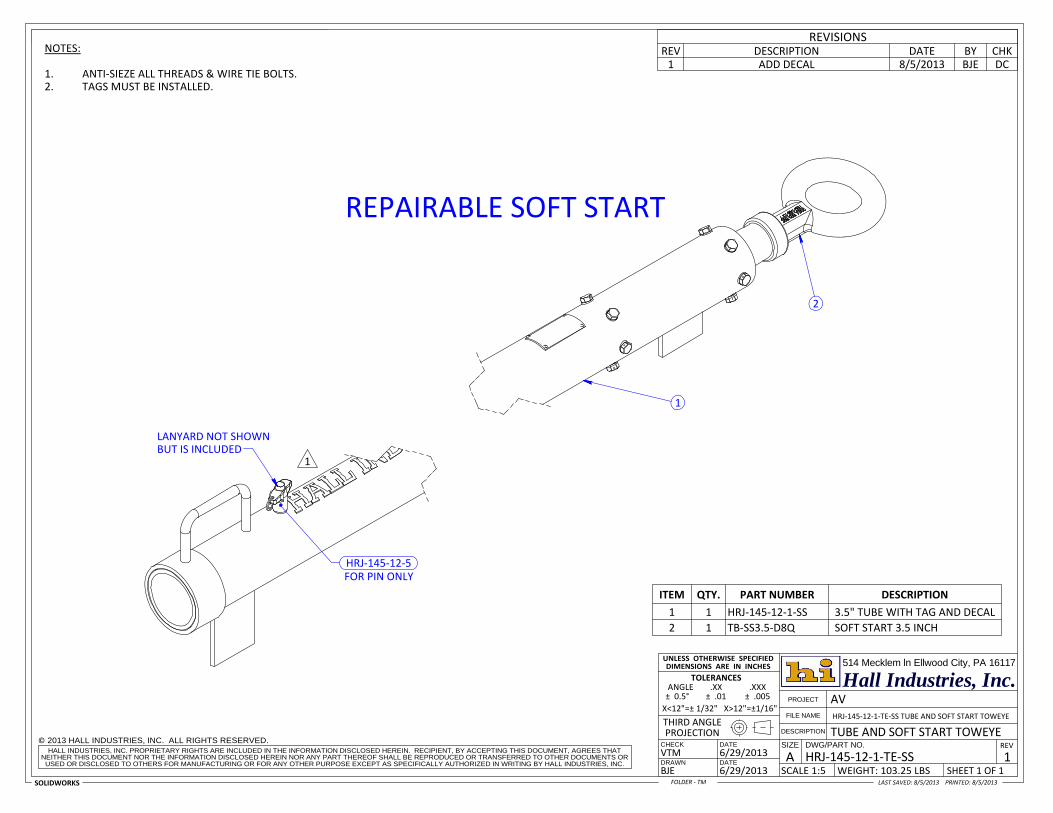
7.3. HRJ‐145‐12‐1‐TE‐SS Towbar Tube with Soft Start Toweye Assembly
7.4. TB‐SS3.5‐D8Q Repairable Soft Start Assembly
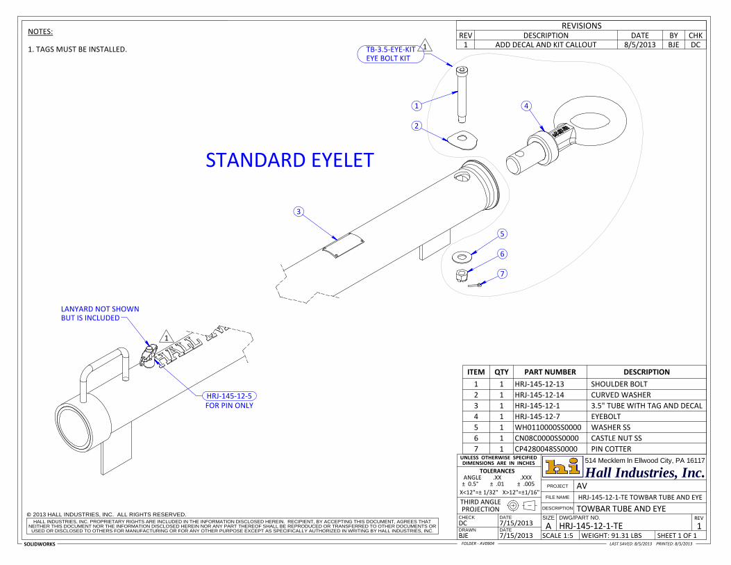
7.5. HRJ‐145‐12‐1‐TE Towbar Tube with Standard Toweye Assembly
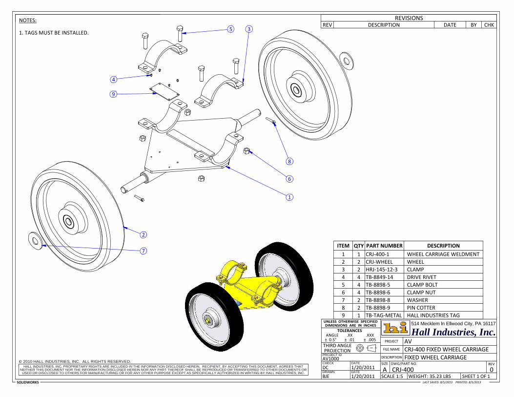
7.6. CRJ‐400 Fixed Wheel Carriage
7.7. REG‐LIFT Regional Towbar Lift ~ Hydraulic 3 ½”
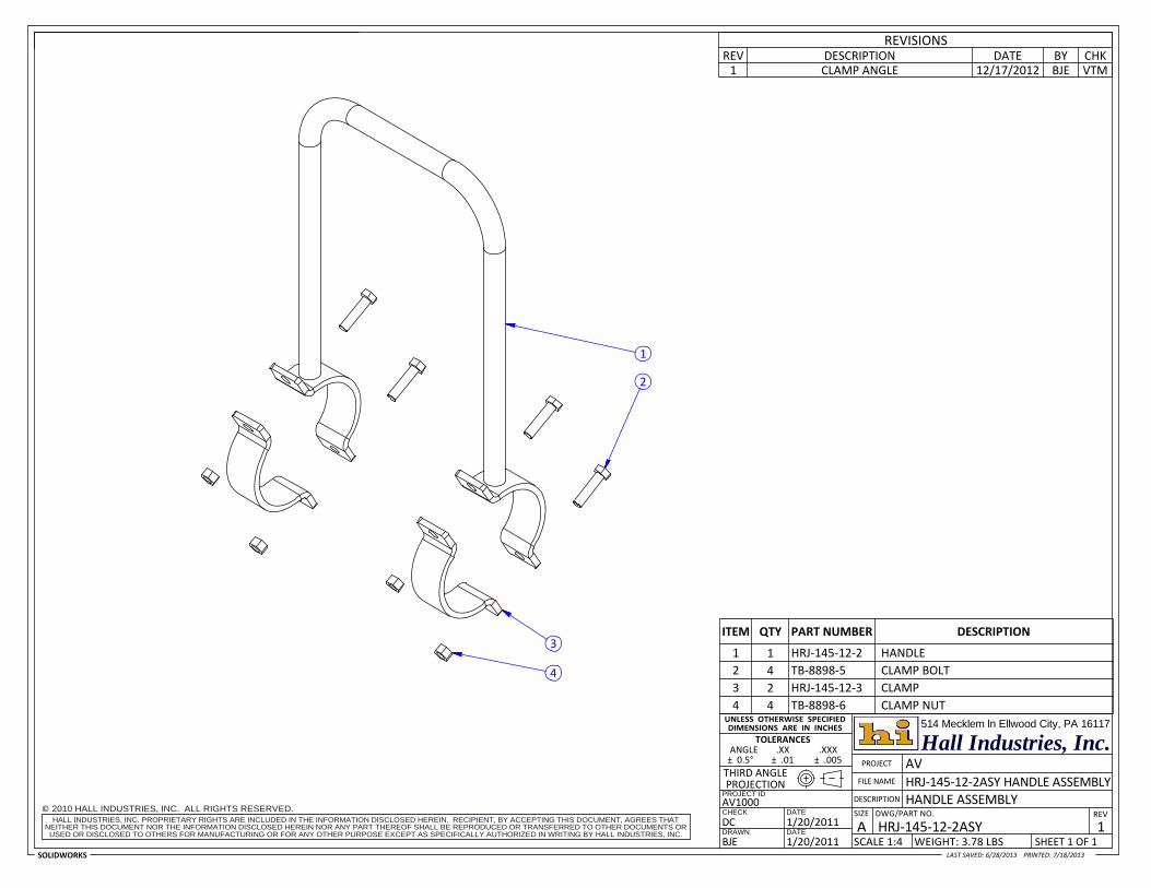
7.8. HRJ‐145‐12‐2ASY Handle Assembly
7.9. AV1009‐0002 Drag Plate 3.5” Bolted
7.10. Soft Start Brochure
7.11. Order Form
7.12. Other Products and Custom Design Services

1 2 3
8 34 " 7
1834 "
Hall Industries, Inc.
DWG/PART NO.DATE
DATE
SIZE
DRAWN
CHECK
SHEET 1 OF 1
X<12"=± 1/32" X>12"=±1/16"
DIMENSIONS ARE IN INCHES
CRJ‐700 TOWBAR COMPLETE
514 Mecklem ln Ellwood City, PA 16117
7/30/2013
THIRD ANGLE PROJECTION
± 0.5° ± .01 ± .005
TOWBAR COMPLETE
BJE
ANGLE .XX .XXX
2013 HALL INDUSTRIES, INC. ALL RIGHTS RESERVED.
SOLIDWORKS
PROJECT
FILE NAME
DESCRIPTION
CRJ‐700AREV
2
AV
©
USED OR DISCLOSED TO OTHERS FOR MANUFACTURING OR FOR ANY OTHER PURPOSE EXCEPT AS SPECIFICALLY AUTHORIZED IN WRITING BY HALL INDUSTRIES, INC.SCALE 1:11 WEIGHT: 207.88 LBS
7/30/2013DCNEITHER THIS DOCUMENT NOR THE INFORMATION DISCLOSED HEREIN NOR ANY PART THEREOF SHALL BE REPRODUCED OR TRANSFERRED TO OTHER DOCUMENTS OR HALL INDUSTRIES, INC. PROPRIETARY RIGHTS ARE INCLUDED IN THE INFORMATION DISCLOSED HEREIN. RECIPIENT, BY ACCEPTING THIS DOCUMENT, AGREES THAT
TOLERANCES
8/5/2013LAST SAVED: 8/1/2013 PRINTED:
UNLESS OTHERWISE SPECIFIED
FOLDER ‐ AV0906
CRJ‐700 & 900 CONFIGURATIONS WITH FIXED WHEELSET W/ HYDRAULIC WHEELSET
STANDARD EYELET CRJ‐700 CRJ‐700‐HL
SOFT START EYELET CRJ‐700‐SS CRJ‐700‐HL‐SS
REV0
DESCRIPTION DATE BY CHK
2. TAGS MUST BE INSTALLED.1. FOR MORE INFORMATION SEE SUB‐ASSEMBLY DRAWINGS.
NOTES:
ORIGINAL 3/27/2002 CJS ‐1 WHEEL CARRIAGE LOCATION 2/28/2003 CJS ‐2 UPDATE DRAWING 7/30/2013 BJE DC
REVISIONS
ITEM QTY PART NUMBER DESCRIPTION
1 1 CRJ‐700‐5 HEAD AND ADAPTER COMPLETE
2 1 HRJ‐145‐12‐1‐TE TOWBAR TUBE AND EYE
3 1 CRJ‐400 FIXED WHEEL CARRIAGE
4 1 HRJ‐145‐12‐2ASY HANDLE ASSEMBLY4
WHEELSET PLACEMENT
29"
24 " 85
1614 "
HANDLE PLACEMENT
12'‐9316 "

Hall Industries, Inc.
DWG/PART NO.DATE
DATE
SIZE
DRAWN
CHECK
SHEET 1 OF 1
X<12"=± 1/32" X>12"=±1/16"
DIMENSIONS ARE IN INCHES
CRJ‐700‐5 HEAD AND ADAPTER COMPLETE
514 Mecklem ln Ellwood City, PA 16117
7/25/2013
THIRD ANGLE PROJECTION
± 0.5° ± .01 ± .005
HEAD AND ADAPTER COMPLETE
BJE
ANGLE .XX .XXX
2013 HALL INDUSTRIES, INC. ALL RIGHTS RESERVED.
SOLIDWORKS
PROJECT
FILE NAME
DESCRIPTION
CRJ‐700‐5 AREV
0
AV
©
USED OR DISCLOSED TO OTHERS FOR MANUFACTURING OR FOR ANY OTHER PURPOSE EXCEPT AS SPECIFICALLY AUTHORIZED IN WRITING BY HALL INDUSTRIES, INC.SCALE 1:6 WEIGHT: 77.56 LBS
7/26/2013DCNEITHER THIS DOCUMENT NOR THE INFORMATION DISCLOSED HEREIN NOR ANY PART THEREOF SHALL BE REPRODUCED OR TRANSFERRED TO OTHER DOCUMENTS OR HALL INDUSTRIES, INC. PROPRIETARY RIGHTS ARE INCLUDED IN THE INFORMATION DISCLOSED HEREIN. RECIPIENT, BY ACCEPTING THIS DOCUMENT, AGREES THAT
TOLERANCES
8/5/2013LAST SAVED: 8/2/2013 PRINTED:
UNLESS OTHERWISE SPECIFIED
FOLDER ‐ AV0906
CRJ‐700 & 900
CHKDATE BY
1.
NOTES:DESCRIPTIONREV
REVISIONS
ITEM QTY PART NUMBER DESCRIPTION
1 2 CRJ‐7‐3 NOSE PIN
2 2 CRJ‐7‐4 SLIDE BOLT
3 2 CRJ‐7‐6 HEAD SPRING
4 1 CRJ‐700‐1 HEAD WELDMENT
5 1 CRJ‐100‐11‐4 SHOULDER BOLT
6 1 CRJ‐700‐11‐1 ADAPTER WELDMENT
7 1 CRJ‐700‐11‐2 SHEAR PIN
8 2 CRJ‐700‐QRP QUICK RELEASE PIN
9 1 CRJ‐G‐L CRJ GUARD, LEFT
10 1 CRJ‐G‐R CRJ GUARD, RIGHT
11 4 H508C0056ZP0000 HH BOLT 1/2"‐13 x 1.75" LONG YZP GR.5
12 6 HRJ‐145‐7‐2 ROLL PIN
13 2 HRJ‐145‐7‐5 RETAINER SCREW
14 2 HRJ‐145‐7‐8 ALUMINUM KNOB
15 2 HRJ‐145‐7‐9 HANDLE‐SLIDE BOLT PIN
16 1 HRJ‐145‐11‐2A STOVER LOCKNUT
17 1 HRJ‐145‐11‐5 WASHER FLAT 5/8" ZP SAE
18 5 TB‐8312‐H7 NYLOC NUT 1/2"‐13
19 2 TB‐9205‐11A‐MKM GREASE FITTING
20 8 WH4520000ZP0000 WASHER 1/2" SAE YZP
7 5
16 17 18
48
11 20 10
18
20
19
1
12
2
13
3
15
14
9
6
CRJ‐700‐11ADAPTER COMPLETE
CRJ‐700‐HEAD HEAD COMPLETE
TB‐TAG‐METAL HALL INDUSTRIES TAG
CRJ‐G‐KIT GUARD KIT(INCLUDES BOTH SIDES)
TB‐8849‐14 DRIVE RIVET
CRJ‐7‐4‐ASYSLIDE BOLT KIT
CRJ‐700‐11‐3 ADAPTER BUSHING
CRJ‐7‐1‐E HEAD BUSHING
BUT IS INCLUDED IN LANYARD NOT SHOWN
HEAD ASSEMBLY
CRJ‐PLAQUE DO NOT TOW PLAQUE
2
REPAIRABLE SOFT START
BUT IS INCLUDEDLANYARD NOT SHOWN
FOR PIN ONLY
1
HRJ‐145‐12‐5
1
BJE
2. TAGS MUST BE INSTALLED.1. ANTI‐SIEZE ALL THREADS & WIRE TIE BOLTS.
DATEDESCRIPTIONREVREVISIONS
BYDC
NOTES: CHK1 ADD DECAL 8/5/2013
ITEM QTY. PART NUMBER DESCRIPTION
1 1 HRJ‐145‐12‐1‐SS 3.5" TUBE WITH TAG AND DECAL
2 1 TB‐SS3.5‐D8Q SOFT START 3.5 INCH
Hall Industries, Inc.
DATE
DWG/PART NO.DATE SIZE
DRAWN
CHECK
SHEET 1 OF 1
DIMENSIONS ARE IN INCHES
X<12"=± 1/32" X>12"=±1/16" HRJ‐145‐12‐1‐TE‐SS TUBE AND SOFT START TOWEYE
514 Mecklem ln Ellwood City, PA 16117
THIRD ANGLE
8/5/2013
HALL INDUSTRIES, INC. PROPRIETARY RIGHTS ARE INCLUDED IN THE INFORMATION DISCLOSED HEREIN. RECIPIENT, BY ACCEPTING THIS DOCUMENT, AGREES THAT
± 0.5° ± .01 ± .005
TUBE AND SOFT START TOWEYE
ANGLE .XX .XXX
2013 HALL INDUSTRIES, INC. ALL RIGHTS RESERVED.
SOLIDWORKS
PROJECT
FILE NAME
DESCRIPTION
HRJ‐145‐12‐1‐TE‐SS AREV
1BJE
PROJECTION
USED OR DISCLOSED TO OTHERS FOR MANUFACTURING OR FOR ANY OTHER PURPOSE EXCEPT AS SPECIFICALLY AUTHORIZED IN WRITING BY HALL INDUSTRIES, INC.SCALE 1:5 WEIGHT: 103.25 LBS
6/29/2013
TOLERANCES
©
AV
6/29/2013
NEITHER THIS DOCUMENT NOR THE INFORMATION DISCLOSED HEREIN NOR ANY PART THEREOF SHALL BE REPRODUCED OR TRANSFERRED TO OTHER DOCUMENTS OR VTM
LAST SAVED: 8/5/2013 PRINTED:
UNLESS OTHERWISE SPECIFIED
FOLDER ‐ TM

2
3
7
618
2
10
5
4
9
8.75WHEN THE NUT (TB‐SS4‐09) IS PROPERLY TIGHTENED
CHKDATE BY
1. USE ANTI‐SEIZE ON ALL THREADED HARDWARE.
NOTES:DESCRIPTIONREV
REVISIONS
ITEM QTY PART NUMBER DESCRIPTION
1 12 8980‐2‐2 WASHER NORDLOCK
2 2 TB‐SS3.5‐02 STOP
3 1 TB‐SS3.5‐04 END GUIDE
4 1 TB‐SS3.5‐06 END GUIDE NO HOLE
5 1 TB‐SS3.5‐10 CUSHION
6 12 TB‐SS3.5‐11 HH BOLT 3/8"‐16 x 3/4" LG ZP GR5 DRILLED HEAD
7 1 TB‐SS4‐05 TUBING
8 1 TB‐SS4‐07 DOWEL PIN 1/4" DIA. x 2" LONG SS
9 1 TB‐SS4‐09 NUT 1‐1/4"‐7 THREAD GR5 ZP
10 1 TB‐SS4‐11 EYE & SHAFT
Hall Industries, Inc.
DWG/PART NO.DATE
DATE
SIZE
DRAWN
CHECK
SHEET 1 OF 1
DIMENSIONS ARE IN INCHES
AV0801/ TB‐SS3.5‐D8Q SOFT START 3.5 INCH ~ FOR MANUAL
514 Mecklem ln Ellwood City, PA 16117
06/29/2013
THIRD ANGLE PROJECTION
± 0.5° ± .01 ± .005
SOFT START 3.5 INCH
BJE
ANGLE .XX .XXX
2013 HALL INDUSTRIES, INC. ALL RIGHTS RESERVED.
SOLIDWORKS
PROJECT
©
FILE NAME
DESCRIPTION
TB‐SS3.5‐D8QAREV
0
AV ~ SS EYE D8Q, HRJFOLDER /
USED OR DISCLOSED TO OTHERS FOR MANUFACTURING OR FOR ANY OTHER PURPOSE EXCEPT AS SPECIFICALLY AUTHORIZED IN WRITING BY HALL INDUSTRIES, INC.SCALE 1:5 WEIGHT: 24.17 LBS
6/29/2013VTMNEITHER THIS DOCUMENT NOR THE INFORMATION DISCLOSED HEREIN NOR ANY PART THEREOF SHALL BE REPRODUCED OR TRANSFERRED TO OTHER DOCUMENTS OR HALL INDUSTRIES, INC. PROPRIETARY RIGHTS ARE INCLUDED IN THE INFORMATION DISCLOSED HEREIN. RECIPIENT, BY ACCEPTING THIS DOCUMENT, AGREES THAT
TOLERANCES
7/18/2013LAST SAVED: 7/18/2013 PRINTED:
UNLESS OTHERWISE SPECIFIED
X<12"=± 1/32" X>12"=±1/16"
FOR PIN ONLY
BUT IS INCLUDED
STANDARD EYELET
3
1
2
4
5
6
LANYARD NOT SHOWN
7
HRJ‐145‐12‐5
TB‐3.5‐EYE‐KITEYE BOLT KIT
1
1
REVISIONSDESCRIPTIONREV
BJE8/5/2013 DCDATE BY CHK
1 ADD DECAL AND KIT CALLOUT
NOTES:
1. TAGS MUST BE INSTALLED.
ITEM QTY PART NUMBER DESCRIPTION
1 1 HRJ‐145‐12‐13 SHOULDER BOLT
2 1 HRJ‐145‐12‐14 CURVED WASHER
3 1 HRJ‐145‐12‐1 3.5" TUBE WITH TAG AND DECAL
4 1 HRJ‐145‐12‐7 EYEBOLT
5 1 WH0110000SS0000 WASHER SS
6 1 CN08C0000SS0000 CASTLE NUT SS
7 1 CP4280048SS0000 PIN COTTER
Hall Industries, Inc.
DATE
DATE
DWG/PART NO.SIZE
DRAWN
CHECK
SHEET 1 OF 1
AV
8/5/2013
X<12"=± 1/32" X>12"=±1/16"
DCHALL INDUSTRIES, INC. PROPRIETARY RIGHTS ARE INCLUDED IN THE INFORMATION DISCLOSED HEREIN. RECIPIENT, BY ACCEPTING THIS DOCUMENT, AGREES THAT
7/15/2013
7/15/2013 A
FILE NAME
DESCRIPTION
TOLERANCESANGLE .XX .XXX
2013 HALL INDUSTRIES, INC. ALL RIGHTS RESERVED.
SOLIDWORKS
NEITHER THIS DOCUMENT NOR THE INFORMATION DISCLOSED HEREIN NOR ANY PART THEREOF SHALL BE REPRODUCED OR TRANSFERRED TO OTHER DOCUMENTS OR
WEIGHT: 91.31 LBS
PROJECT
PROJECTION
HRJ‐145‐12‐1‐TE TOWBAR TUBE AND EYE
1
± 0.5° ± .01 ± .005
HRJ‐145‐12‐1‐TE
©REV
THIRD ANGLE
DIMENSIONS ARE IN INCHES
BJE
514 Mecklem ln Ellwood City, PA 16117
TOWBAR TUBE AND EYE
USED OR DISCLOSED TO OTHERS FOR MANUFACTURING OR FOR ANY OTHER PURPOSE EXCEPT AS SPECIFICALLY AUTHORIZED IN WRITING BY HALL INDUSTRIES, INC.SCALE 1:5
LAST SAVED: 8/5/2013 PRINTED:
UNLESS OTHERWISE SPECIFIED
FOLDER ‐ AV0904
Hall Industries, Inc.
2010 HALL INDUSTRIES, INC. ALL RIGHTS RESERVED.©HALL INDUSTRIES, INC. PROPRIETARY RIGHTS ARE INCLUDED IN THE INFORMATION DISCLOSED HEREIN. RECIPIENT, BY ACCEPTING THIS DOCUMENT, AGREES THAT
NEITHER THIS DOCUMENT NOR THE INFORMATION DISCLOSED HEREIN NOR ANY PART THEREOF SHALL BE REPRODUCED OR TRANSFERRED TO OTHER DOCUMENTS OR USED OR DISCLOSED TO OTHERS FOR MANUFACTURING OR FOR ANY OTHER PURPOSE EXCEPT AS SPECIFICALLY AUTHORIZED IN WRITING BY HALL INDUSTRIES, INC.
DATE
DATE
PROJECT ID
DRAWN
CHECK
SHEET 1 OF 1
FIXED WHEEL CARRIAGEAV1000
± 0.5° ± .01 ± .005
1/20/20118/5/2013
WEIGHT: 35.23 LBSSCALE 1:5
514 Mecklem ln Ellwood City, PA 16117
BJESOLIDWORKS
PROJECT
FILE NAME CRJ‐400 FIXED WHEEL CARRIAGE
CRJ‐400AREV
DESCRIPTION
0
THIRD ANGLE
DWG/PART NO.1/20/2011
AV
DC
ANGLE .XX .XXX TOLERANCES
PROJECTION
SIZE
LAST SAVED: 8/5/2013 PRINTED:
UNLESS OTHERWISE SPECIFIED DIMENSIONS ARE IN INCHES
CHKDATE BY
1. TAGS MUST BE INSTALLED.
NOTES:DESCRIPTIONREV
REVISIONS
ITEM QTY PART NUMBER DESCRIPTION
1 1 CRJ‐400‐1 WHEEL CARRIAGE WELDMENT
2 2 CRJ‐WHEEL WHEEL
3 2 HRJ‐145‐12‐3 CLAMP
4 4 TB‐8849‐14 DRIVE RIVET
5 4 TB‐8898‐5 CLAMP BOLT
6 4 TB‐8898‐6 CLAMP NUT
7 2 TB‐8898‐8 WASHER
8 2 TB‐8898‐9 PIN COTTER
9 1 TB‐TAG‐METAL HALL INDUSTRIES TAG
3
6
8
1
4
2
7
5
9

ITEM QTY PART NUMBER DESCRIPTION
1 1 LIFT‐1 PUMP MOUNTING BRACKET
2 1 LIFT‐4 LOWER PIVOT SHAFT
3 1 LIFT‐3 WHEEL ARM WELDMENT
4 1 LIFT‐2RWHEEL ARM PIVOT SHAFT/ W 2 COLLARS
5 1 LIFT‐6 WHEEL ARM PIVOT WELDMENT
6 2 LIFT‐8 HEX SOCKET SHOULDER BOLT
7 2 TB‐8986‐9 FLAT WASHER ZP
9 4 LIFT‐11 FLAT WASHER SAE ZP
10 2 LIFT‐12 COTTER PIN, PIVOT SHAFT
11 1 LIFT‐14 CLEVIS PIN
13 4 TB‐8714‐1 HEX BOLT GR5 ZP
14 2 TB‐8898‐7 WHEEL 10"
15 2 TB‐8898‐8 FLAT WASHER USS ZP
16 4 TB‐8898‐9 COTTER PIN, AXLE
17 1 TB‐8714‐20HYD CYLINDER W/QUICK DISC, CPLG
18 1 TB‐8714‐23 HYDRAULIC HOSE
19 1 TB‐8714‐24 HYDRAULIC PUMP ASSEMBLY
20 4 HRJ‐145‐12‐3 HANDLE/WHEEL ASSY CLAMP
21 8 TB‐8898‐5 HEX BOLT GR5 ZP
22 8 TB‐8898‐6 HEX NUT NYLOCK ZP
23 4 TB‐8714‐2 LOCK WASHER ZP
24 2 TB‐8714‐10 EXTENSION SPRING
25 1 TB‐TAG‐METAL IDENTIFICATION TAG (NOT SHOWN)
26 4 TB‐8849‐14 DRIVE RIVET FOR TAG (NOT SHOWN)
Hall Industries, Inc.
2010 HALL INDUSTRIES, INC. ALL RIGHTS RESERVED.©HALL INDUSTRIES, INC. PROPRIETARY RIGHTS ARE INCLUDED IN THE INFORMATION DISCLOSED HEREIN. RECIPIENT, BY ACCEPTING THIS DOCUMENT, AGREES THAT
NEITHER THIS DOCUMENT NOR THE INFORMATION DISCLOSED HEREIN NOR ANY PART THEREOF SHALL BE REPRODUCED OR TRANSFERRED TO OTHER DOCUMENTS OR USED OR DISCLOSED TO OTHERS FOR MANUFACTURING OR FOR ANY OTHER PURPOSE EXCEPT AS SPECIFICALLY AUTHORIZED IN WRITING BY HALL INDUSTRIES, INC.
DATE
DATE
PROJECT ID
DRAWN
CHECK
SHEET 1 OF 1
THIRD ANGLE
AV1000
514 Mecklem ln Ellwood City, PA 16117
11/20/2010
PROJECTION
7/18/2013
± 0.5° ± .01 ± .005
REGIONAL TOWBAR LIFTREG‐LIFT REGIONAL TOWBAR LIFT
BJESOLIDWORKS
PROJECT
FILE NAME
DESCRIPTION
REG‐LIFTAREVSIZE
0 DWG/PART NO.
SCALE 1:1 WEIGHT: 50 LBS
11/20/2010DC
ANGLE .XX .XXX TOLERANCES
LAST SAVED: 4/8/2011 PRINTED:
UNLESS OTHERWISE SPECIFIED DIMENSIONS ARE IN INCHES
Hall Industries, Inc.
2010 HALL INDUSTRIES, INC. ALL RIGHTS RESERVED.©HALL INDUSTRIES, INC. PROPRIETARY RIGHTS ARE INCLUDED IN THE INFORMATION DISCLOSED HEREIN. RECIPIENT, BY ACCEPTING THIS DOCUMENT, AGREES THAT
NEITHER THIS DOCUMENT NOR THE INFORMATION DISCLOSED HEREIN NOR ANY PART THEREOF SHALL BE REPRODUCED OR TRANSFERRED TO OTHER DOCUMENTS OR USED OR DISCLOSED TO OTHERS FOR MANUFACTURING OR FOR ANY OTHER PURPOSE EXCEPT AS SPECIFICALLY AUTHORIZED IN WRITING BY HALL INDUSTRIES, INC.
DATE
DATE
PROJECT ID
DRAWN
CHECK
SHEET 1 OF 1
THIRD ANGLE
AV1000
514 Mecklem ln Ellwood City, PA 16117
1/20/2011
PROJECTION
7/18/2013
± 0.5° ± .01 ± .005
HANDLE ASSEMBLYHRJ‐145‐12‐2ASY HANDLE ASSEMBLY
BJESOLIDWORKS
PROJECT
FILE NAME
DESCRIPTION
HRJ‐145‐12‐2ASYAREVSIZE
1 DWG/PART NO.
AV
SCALE 1:4 WEIGHT: 3.78 LBS
1/20/2011DC
ANGLE .XX .XXX TOLERANCES
LAST SAVED: 6/28/2013 PRINTED:
UNLESS OTHERWISE SPECIFIED DIMENSIONS ARE IN INCHES
2
3
1
4
VTM12/17/2012 BJECLAMP ANGLE1CHKBYDATEDESCRIPTION
REVISIONSREV
ITEM QTY PART NUMBER DESCRIPTION
1 1 HRJ‐145‐12‐2 HANDLE
2 4 TB‐8898‐5 CLAMP BOLT
3 2 HRJ‐145‐12‐3 CLAMP
4 4 TB‐8898‐6 CLAMP NUT

2
3
1
4
CHKREV BYDATEDESCRIPTION
PLATES HAVE BEEN WORN DOWN.1. USE WHEN FACTORY INSTALLED DRAG
NOTES: REVISIONS
ITEM QTY PART NUMBER DESCRIPTION
1 2 TB‐8898‐6 CLAMP NUT
2 1 HRJ‐145‐12‐3 CLAMP
3 1 AV1009‐3001 DRAG PLATE WELDMENT
4 2 TB‐8898‐5 CLAMP BOLT
Hall Industries, Inc.
2010 HALL INDUSTRIES, INC. ALL RIGHTS RESERVED.©HALL INDUSTRIES, INC. PROPRIETARY RIGHTS ARE INCLUDED IN THE INFORMATION DISCLOSED HEREIN. RECIPIENT, BY ACCEPTING THIS DOCUMENT, AGREES THAT
NEITHER THIS DOCUMENT NOR THE INFORMATION DISCLOSED HEREIN NOR ANY PART THEREOF SHALL BE REPRODUCED OR TRANSFERRED TO OTHER DOCUMENTS OR USED OR DISCLOSED TO OTHERS FOR MANUFACTURING OR FOR ANY OTHER PURPOSE EXCEPT AS SPECIFICALLY AUTHORIZED IN WRITING BY HALL INDUSTRIES, INC.
DATE
DATE
PROJECT ID
DRAWN
CHECK
SHEET 1 OF 1
THIRD ANGLE
AV1009
514 Mecklem ln Ellwood City, PA 16117
6/27/2012
PROJECTION
7/18/2013
± 0.5° ± .01 ± .005
TOWBAR DRAG PLATE 3.5 INCH BOLTED
AV1009‐0002 TOWBAR DRAG PLATE 3.5 INCH BOLTED
BJESOLIDWORKS
PROJECT
FILE NAME
DESCRIPTION
AV1009‐0002AREVSIZE
0 DWG/PART NO.
AV
SCALE 1:2 WEIGHT: 2.57 LBS
6/27/2012BJE
ANGLE .XX .XXX TOLERANCES
LAST SAVED: 7/10/2013 PRINTED:
UNLESS OTHERWISE SPECIFIED DIMENSIONS ARE IN INCHES

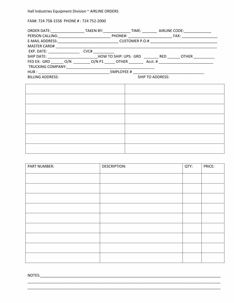
Hall Industries Equipment Division ~ AIRLINE ORDERS
FAX#: 724 758‐1558 PHONE # : 724 752‐2000
ORDER DATE:________________ TAKEN BY:_____________ TIME: _______ AIRLINE CODE:_____________ PERSON CALLING:_________________________ PHONE#: _____________________ FAX: _________________ E‐MAIL ADDRESS:_____________________________ CUSTOMER P.O.# ________________________________ MASTER CARD# _____________________________________________________________________________ EXP. DATE: _______________ CVC# __________ SHIP DATE: ________________________HOW TO SHIP: UPS: GRD _______ RED ______ OTHER __________ FED EX: GRD ______ O/N ________ O/N P1 _____ OTHER _______ Acct. # __________________________ TRUCKING COMPANY:__________________________________________ HUB : __________________________________ EMPLOYEE # __________________________________ BILLING ADDRESS: SHIP TO ADDRESS:
PART NUMBER: DESCRIPTION: QTY: PRICE:
NOTES:______________________________________________________________________________________
____________________________________________________________________________________________
____________________________________________________________________________________________

M a n u f a c t u r i n g S o l u t i o n s S i n c e 1 9 6 6
Page 1
Other Products and Custom Design Services:
Hall Industries provides a number of additional products beyond our towbar line. Some of the custom projects that we have done are shown below. We have our own engineering staff along with machine, fabrication, and GSE maintenance shops. We can design and build your ideas to increase safety, productivity, and profits.
0017-0001 Custom Towbar (Solve a Problem) <<This project involved designing and manufacturing a custom towbar to be used in the Nuclear Industry. This towbar shipped complete with custom shear pins calibrated to the application.
IA-8980 Preconditioned Air Inlet (PCA) Adapters << Our PCA Inlet Adapters are part of our GSE product line. We inventory all of the parts and can ship usually the same day as ordered.>>
0010-0001 Certified Transmission Lifting Bracket (Meet a Demand) A customer came to us with a lifting problem. They needed a tested and certified lifting bracket to prevent them from getting cited by OSHA. We designed, tested, and fabricated a solution. >>
<<1000-3002 Adapter 8312 to Tronair 1000-0001 Hydro Adapter Assembly>> Hall Industries offers adapters for nearly every towbar (even competitors) that allow you to use our towbar tubes / heads with your existing equipment.
Besides the products listed above some of the other things that we sell include PCA ducting, Solid PBB tires, and baggage cart tires.
Feel free to contact us about your GSE problems; after all we are “The Problem Solvers”.