towards sustainable urban transportation - diva portal
TRANSCRIPT

Towards sustainable urban transportation Test, demonstration and development of fuel cell and
hybrid-electric buses
Anders Folkesson
Doctoral Thesis 2008
KTH - Royal Institute of Technology School of Chemical Science and Engineering
Department of Chemical Engineering and Technology Energy Processes
Stockholm, Sweden

Towards sustainable urban transportation – Test, demonstration and development of fuel cell and hybrid-electric buses
KTH - Royal Institute of Technology School of Chemical Science and Engineering Department of Chemical Engineering and Technology Energy Processes SE-100 44 Stockholm Sweden Copyright © Anders Folkesson, 2008 All rights reserved Printed in Sweden Universitetsservice US AB Stockholm TRITA-CHE Report 2008:30 ISSN 1654-1081 ISBN 978-91-7178-940-2

iii
Till Anna, Albin, mamma och pappa “The automobile, especially, is remarkably addictive. I have described it as a suit of armor with 200 horses inside, big enough to make love in. It is not surprising that it is popular. It turns its driver into a knight with the mobility of the aristocrat and perhaps some of his other vices. The pedestrian and the person who rides public transportation are, by comparison, peasants looking up with almost inevitable envy at the knights riding by in their mechanical steeds. Once having tasted the delights of a society in which almost everyone can be a knight, it is hard to go back to being peasants. I suspect, therefore, that there will be very strong technological pressures to preserve the automobile in some form, even if we have to go to nuclear fusion for the ultimate source of power and to liquid hydrogen for the gasoline substitute. The alternative would seem to be a society of contented peasants, each cultivating his own little garden and riding to work on the bus, or even on an electric streetcar. Somehow this outcome seems less plausible than a desperate attempt to find new sources of energy to sustain our knightly mobility.” Kenneth E. Boulding Science, Vol. 184, No. 4134, 255-257, 1974 Bilarna borde ha avgasrören inte i aktern, utan i fören. Då blir det ju den som kör Som dör. Tage Danielsson ”Rättvis tanke av primitiv kajakägare” ur Tage Danielssons samlade dikter, 1967-1967

Towards sustainable urban transportation – Test, demonstration and development of fuel cell and hybrid-electric buses
iv

Abstract
v
Abstract Keywords: acceptance, analysis, auxiliary system, bus, Clean Urban Transport for Europe, concept, CUTE, demonstration, driver, drive cycle, duty cycle, energy flow, evaluation, fuel cell, heavy duty vehicle, hybrid management, hybrid vehicle, hydrogen, passenger, PEM, safety, Sankey diagram, series hybrid, sustainable, test, urban transport, vehicle simulation Several aspects make today’s transport system non-sustainable: • Production, transport and combustion of fossil fuels lead to global and local environmental
problems. • Oil dependency in the transport sector may lead to economical and political instability. • Air pollution, noise, congestion and land-use may jeopardise public health and quality of life,
especially in urban areas. In a sustainable urban transport system most trips are made with public transport because high convenience and comfort makes travelling with public transport attractive. In terms of emissions, including noise, the vehicles are environmentally sustainable, locally as well as globally. Vehicles are energy-efficient and the primary energy stems from renewable sources. Costs are reasonable for all involved, from passengers, bus operators and transport authorities to vehicle manufacturers. The system is thus commercially viable on its own merits. This thesis presents the results from three projects involving different concept buses, all with different powertrains. The first two projects included technical evaluations, including tests, of two different fuel cell buses. The third project focussed on development of a series hybrid-bus with internal combustion engine intended for production around 2010. The research on the fuel cell buses included evaluations of the energy efficiency improvement potential using energy mapping and vehicle simulations. Attitudes to hydrogen fuel cell buses among passengers, bus drivers and bus operators were investigated. Safety aspects of hydrogen as a vehicle fuel were analysed and the use of hydrogen compared to electrical energy storage were also investigated. One main conclusion is that a city bus should be considered as one energy system, because auxiliaries contribute largely to the energy use. Focussing only on the powertrain is not sufficient. The importance of mitigating losses far down an energy conversion chain is emphasised. The Scania hybrid fuel cell bus showed the long-term potential of fuel cells, advanced auxiliaries and hybrid-electric powertrains, but technologies applied in that bus are not yet viable in terms of cost or robustness over the service life of a bus. Results from the EU-project CUTE show that hydrogen fuelled fuel cell buses are viable for real-life operation. Successful operation and public acceptance show that focus on robustness and cost in vehicle design were key success factors, despite the resulting poor fuel economy. Hybrid-electric powertrains are feasible in stop-and-go city operation. Fuel consumption can be reduced, comfort improved, noise lowered and the main power source downsized and operated less dynamically. The potential for design improvements due to flexible component packaging is implemented in the Scania hybrid concept bus. This bus and the framework for its hybrid management system are discussed in this thesis. The development of buses for a more sustainable urban transport should be made in small steps to secure technical and economical realism, which both are needed to guarantee commercialisation and volume of production. This is needed for alternative products to have a significant influence. Hybrid buses with internal combustion engines running on renewable fuel is tomorrow’s technology, which paves the way for plug-in hybrid, battery electric and fuel cell hybrid vehicles the day after tomorrow.

Towards sustainable urban transportation – Test, demonstration and development of fuel cell and hybrid-electric buses
vi

Sammanfattning
vii
Sammanfattning
Nyckelord: acceptans, analys, hjälpaggregat, buss, Clean Urban Transport for Europe, koncept, CUTE, demonstration, körcykel, förare, energiflöde, utvärdering, bränslecell, tunga fordon, hybridsystemkontroll, hybridfordon, vätgas, passagerare, PEM, säkerhet, Sankey-diagram, seriehybrid, uthållig, hållbar, test, stadstransport, fordonssimulering Ett antal faktorer gör att dagens transportsystem inte är långsiktigt hållbart: • Produktion, transporter och förbränning av fossila bränslen bidrar till globala och lokala
miljöproblem. • Oljeberoendet inom transportsektorn kan komma att bidra till ekonomisk och politisk
instabilitet. • Luftföroreningar, buller, trängsel och markanvändningen för vägar äventyrar både hälsa och
livskvalitet för boende i städer. I ett hållbart transportsystem sker de flesta resor med kollektiva färdmedel då dessa är smidiga och komfortabla och därmed attraktiva för resenärerna. Nivån av emissioner med lokal såväl som global påverkan samt även buller är på miljömässigt hållbara nivåer. Fordonen är energieffektiva och primärenergin kommer från förnybara energikällor. Kostnaderna är rimliga för alla inblandade parter, från passagerare, bussoperatörer, och trafikhuvudmän, till fordonstillverkare. Systemet är därmed kommersiellt gångbart på egna meriter. I denna avhandling presenteras resultat från tre olika projekt med tre olika konceptbussar, alla med olika drivlinor. De två första projekten omfattade tekniska utvärderingar, inklusive praktiska tester på två olika typer av bränslecellsbussar. Det tredje projektet var ett utvecklingsprojekt, i vilket en seriehybridbuss med förbränningsmotor togs fram med sikte på lansering kring 2010. Bränslecellsbussprojekten omfattade bland annat utvärdering av möjligheterna till att förbättra bränsleekonomin i bussarna, vilket bl.a. undersöktes genom kartläggning av energiflödena i bussarna samt fordonssimulering. Attityderna gentemot bränslecellsbussarna hos passagerare, bussförare och bussoperatörer undersöktes också. Dessutom undersöktes säkerhetsaspekter med vätgas som fordonsbränsle, liksom lämpligheten att använda vätgas och bränsleceller jämfört med andra energilagringsmetoder i några utvalda applikationer. En viktig slutsats är att en stadsbuss bör betraktas som ett enda energisystem i och med att kringsystemen kraftigt påverkar energiförbrukningen. Att endast fokusera på drivlinan är inte tillräckligt. Vikten av att minska förluster lång ner i en kedja av energiomvandlingar påvisades. Utvärderingen Scanias bränslecellhybridbuss visade på potentialen med bränsleceller, avancerade hjälpaggregat och hybriddrivlinor, men tekniken som användes i bussen är inte ännu gångbar med avseende på kostnader och kvalitet under bussens livslängd. Resultaten från EU-projektet CUTE visade att vätgasdrivna bränslecellsbussar är gångbara, om än med en hög bränsleförbrukning. Den lyckade driften av bussarna och acceptansen hos allmänheten visar att fokus på robusthet och låga kostnader var viktiga framgångsfaktorer. Hybriddrivlinor är lämpliga i stadsbusstrafik med många start och stopp. Bränsleförbrukningen kan minskas, komforten förbättras, bullernivån sänkas och huvudkraftkällan kan göras mindre samt dessutom köras mindre dynamiskt. Komponenterna kan placeras relativt fritt i en seriehybriddrivlina, vilket nyttjades vid framtagandet av Scanias hybridkonceptbuss. Denna buss samt uppbyggnaden av dess hybridkontrollsystem diskuteras i avhandlingen. Utvecklingen av hållbara stadsbussar måste ske i små steg för att säkerställa ekonomiskt och tekniskt realistiska lösningar, vilket är ett måste för massproduktion. Detta i sin tur krävs om fordonen ska ha en betydande inverkan på framtidens transportsystem. Hybridbussar med förbränningsmotorer som går på förnybara bränslen är den bästa lösningen under överskådlig tid och de banar dessutom väg för s.k. plug-in hybrider, batteri- och bränslecellshybrider.

Towards sustainable urban transportation – Test, demonstration and development of fuel cell and hybrid-electric buses
viii
List of appended Papers This thesis is based on the following Papers, referred to by Roman numerals I-X. The Papers are appended at the end of the thesis.
I. Real life testing of a hybrid PEM fuel cell bus Anders Folkesson, Christian Andersson, Per Alvfors, Mats Alaküla and Lars Overgaard, Journal of Power Sources, Vol. 118, No. 1-2, 349-357, 2003. I was responsible for the fuel cell tests and complete vehicle energy mapping and shared the practical responsibility for planning and realising the tests performed. I presented this paper at the Grove Fuel Cell Conference, Amsterdam, 2002.
II. Fuel cell buses in the Stockholm CUTE project – First experiences from a climate perspective Kristina Haraldsson, Anders Folkesson and Per Alvfors, Journal of Power Sources, Vol. 145, No. 2, 620-631, 2005. I shared the responsibility for work package 4 (WP4) of the CUTE project, including test design, execution and evaluation of results. I presented this paper at the Grove Fuel Cell Conference in Munich, 2004.
III. Energy system analysis of the fuel cell buses operated in the project: Clean Urban Transport for Europe Maria Saxe, Anders Folkesson and Per Alvfors, Energy, Vol. 33, 689-711, 2008. I shared the responsibility for work package 4 (WP4) of the CUTE project. My work included test design and execution, evaluation and compilation of results forming the basis for this paper.
IV. Study of the fuel economy improvement potential of fuel cell buses by vehicle simulation Anders Folkesson, Anders Lindfeldt, Maria Saxe and Per Alvfors, Submitted for publication. The simulation model used in this study was developed by Anders Lindfeldt in his M.Sc. Thesis project, which I initiated and supervised.
V. A first report on the attitude towards hydrogen fuel cell buses in Stockholm Kristina Haraldsson, Anders Folkesson, Maria Saxe and Per Alvfors, International Journal of Hydrogen Energy, Vol. 31, No. 3, 317-325, 2006. I shared the responsibility for work package 4 (WP4) of the CUTE project, including the development of the survey and analysis of the results presented in this study.
VI. A follow-up and conclusive report on the attitude towards hydrogen fuel cell buses in the CUTE project – From passengers in Stockholm to bus operators in Europe Maria Saxe, Anders Folkesson and Per Alvfors, International Journal of Hydrogen Energy, Vol. 32, No. 3, 4295-4305, 2007. I shared the responsibility for work package 4 (WP4) of the CUTE project, including the development of the main survey in this study. I participated in the assessment of the data and to the conclusions in this study. Maria Saxe was responsible for the statistical analysis and did most of the writing of the paper.

List of appended Papers
ix
VII. Safety issues with hydrogen as a vehicle fuel Mårten Niklasson, David Gårsjö, Anders Folkesson, Per Alvfors, Eva Sunnerstedt and Joakim Hägvall, Proceedings from Electrical Vehicle Symposium 21 (EVS21), Monaco, 2005. Updated (appended) version of the paper available at www.branslecellsbuss.se (29 February 2008). This paper is based on Mårten Niklasson’s and David Gårsjö’s M.Sc. Thesis project, which I initiated and supervised.
VIII. Key factors in planning a sustainable energy future including hydrogen and fuel cells Lars Hedström, Maria Saxe, Anders Folkesson, Cecilia Wallmark, Kristina Haraldsson, Mårten Bryngelsson and Per Alvfors, Bulletin of Science, Technology & Society, Vol. 26, No. 4, 264-277, 2006. I was responsible for the transportation part of this paper.
IX. Scania hybrid concept – with robust technology into the future Lars Overgaard and Anders Folkesson, Proceedings from the 57th UITP World Congress, Helsinki, 2007. I did the main part of the writing of this paper and have been involved in the project from start with responsibilities for defining performance targets, test design, noise performance, energy management, market study and internal and external communication i.a.
X. Targets, constraints and rules for hybrid management in a series hybrid bus intended for commercial introduction Anders Folkesson, Christian Gravesen and Magnus Neuman, Accepted for publication in Society of Automotive Engineers, SAE Paper 2008-01-1563, 2008. I shared the responsibility for defining performance targets and for the development of the hybrid management strategy during the Scania hybrid concept project.
Related publications not included in this thesis
1. Analysis of test results from a hybrid electric fuel cell bus Anders Folkesson, Christian Andersson, Per Alvfors, Mats Alaküla and Lars Overgaard, Proceedings from Electrical Vehicle Symposium 20 (EVS20), Long Beach, California, USA, 2003.
2. Demonstration of fuel cell buses under varying climate conditions – the Stockholm CUTE project Björn Hugosson, Kristina Haraldsson and Anders Folkesson, Proceedings from Electrical Vehicle Symposium 20 (EVS20), Long Beach, California, USA, 2003.
3. CUTE detailed summary of achievements EvoBus GmbH, Käsbohrerstrasse 13, 89077 Ulm, Germany, 2006. Available at: http://ec.europa.eu/energy/res/fp6_projects/doc/hydrogen/deliverables/ summary.pdf and http://www.fuel-cell-bus-club.com/modules/UpDownload/ store_folder/Publications/DETAILED_SCREEN.pdf ( 29 Feb. 2008)
Beside these publications, results of my research have been used in internal reports at Scania and in the CUTE-project and are background for patent applications.

Towards sustainable urban transportation – Test, demonstration and development of fuel cell and hybrid-electric buses
x
Table of contents 1. Thesis outline ___________________________________________________ 1 2. Introduction _____________________________________________________3
2.1 Scope of the thesis _________________________________________________ 3 2.2 Research projects__________________________________________________ 3
2.2.1. The Scania hybrid fuel cell concept bus project _________________________________ 4 2.2.2. The clean urban transport for Europe project – CUTE___________________________ 4 2.2.3. The Scania hybrid concept bus project _______________________________________ 4
2.3 Research journey, special contributions of thesis, research ethics and limitations ______________________________________________________________ 5
2.3.1. Research journey________________________________________________________ 5 2.3.2. Special contributions of this thesis, research ethics and limitations __________________ 6
3. Methodology ____________________________________________________9 3.1 Definition of the performed research __________________________________ 9 3.2 Papers I-III ______________________________________________________ 9 3.3 Paper IV _________________________________________________________ 9 3.4 Papers V-VI _____________________________________________________ 10 3.5 Paper VII _______________________________________________________ 10 3.6 Paper VIII ______________________________________________________ 10 3.7 Paper IX ________________________________________________________ 10 3.8 Paper X _________________________________________________________ 10
4. Background ____________________________________________________ 11 4.1 Definition of sustainable transportation ______________________________ 11 4.2 Issues that make today’s transportation non-sustainable and solutions for more sustainable future transportation___________________________________________ 12
4.2.1. CO2, climate change and oil dependency_____________________________________ 12 4.2.2. Traffic congestion and road space__________________________________________ 13 4.2.3. Exhaust emissions______________________________________________________ 13 4.2.4. Noise _______________________________________________________________ 15
4.3 Key factors for sustainable public transportation systems ________________ 16 4.4 City buses in commercial operation – characteristics and driving forces ____ 17
4.4.1. General considerations about vehicle demands ________________________________ 17 4.4.2. Primary demands – driven by the commercial reality for bus operators ______________ 18 4.4.3. Secondary demands – reflecting the political will via transport authorities ____________ 19 4.4.4. Demands from vehicle manufacturers_______________________________________ 20 4.4.5. Duty cycles ___________________________________________________________ 20
4.5 Urban buses as pioneering vehicles __________________________________ 21 4.6 Overview of alternative powertrains__________________________________ 22
4.6.1. A vehicle as one energy system ____________________________________________ 22 4.6.2. Fuels________________________________________________________________ 23 4.6.3. Hybrid powertrains_____________________________________________________ 24 4.6.4. Fuel cells_____________________________________________________________ 25 4.6.5. Energy storage systems __________________________________________________ 25 4.6.6. Auxiliary systems ______________________________________________________ 26
4.7 Examples of products and demonstration projects with hybrid and fuel cell buses 26
5. Evaluation of fuel cell buses by tests, vehicle simulation and mapping of energy flows – reflections on Papers I-IV ________________________________ 27
5.1 Technical descriptions of the buses__________________________________ 27 5.2 Tests and operation with the Scania hybrid fuel cell bus _________________ 28 5.3 Operation results with the Mercedes-Benz fuel cell bus in the CUTE project 30 5.4 Test-based fuel economy analysis of the buses in CUTE ________________ 30 5.5 Vehicle modelling-based fuel economy analysis of the buses in CUTE_____ 32

Table of contents
xi
6. Acceptance of hydrogen and fuel cells and recommendations for future demonstration projects – reflections on Papers V-VI_______________________ 35
6.1 Background to public acceptance ___________________________________ 35 6.2 Scope of presented studies of public acceptance _______________________ 36 6.3 Results from the Stockholm surveys among passengers _________________ 36 6.4 Results from the surveys among drivers ______________________________ 37 6.5 Recommendations for future demonstration projects ___________________ 38
7. Considerations related to the vision of a hydrogen economy – reflections on Papers VII-VIII _____________________________________________________ 41
7.1 The vision of a hydrogen economy __________________________________ 41 7.2 Safety aspects with hydrogen as a vehicle fuel _________________________ 42
7.2.1. Properties of hydrogen compared to other fuels _______________________________ 43 7.2.2. Risk analysis __________________________________________________________ 44 7.2.3. Rules, conclusions and recommendations ____________________________________ 46
7.3 Hydrogen and fuel cells compared to competing technologies____________ 46 7.3.1. Stationary electric energy storage___________________________________________ 47 7.3.2. Long range energy distribution ____________________________________________ 47 7.3.3. Electric buffer needs in an energy system with intermittent energy production ________ 47 7.3.4. Feasibility of fuel cell vehicles and battery electric vehicles _______________________ 47
8. A series hybrid bus as a feasible short-to-mid-term solution and a platform for the future – reflections on Papers IX-X _______________________________ 51
8.1 A concept study forming background for the hybrid concept bus _________ 51 8.2 Targets for the bus________________________________________________ 51 8.3 Design of the bus_________________________________________________ 52 8.4 The series-hybrid powertrain _______________________________________ 54 8.5 Designing for low noise ___________________________________________ 55 8.6 Hybrid management control strategy ________________________________ 58
9. Conclusions ____________________________________________________ 63 9.1 Concluding remarks ______________________________________________ 63 9.2 Overall conclusions _______________________________________________ 66
10. Future work ____________________________________________________ 67 11. Acknowledgements ______________________________________________ 69
11.1 Personal acknowledgements________________________________________ 69 11.2 Financial acknowledgements _______________________________________ 70 11.3 Personal inspiration for my research _________________________________ 70
12. References _____________________________________________________ 71

Towards sustainable urban transportation – Test, demonstration and development of fuel cell and hybrid-electric buses
xii

1. Thesis outline
1
1. Thesis outline This thesis is based on ten research papers and is structured as follows: Chapter 2 presents an introduction of the research work and projects, on which this thesis is based. Chapter 3 is the methodology chapter. Chapter 4 gives the background and reasons for the research. First a definition of sustainability is given. The problems with today’s road transportation in general and urban transportation in particular are presented. Requirements and driving forces in the urban bus operation business are discussed. Ways of solving the problems stated above are discussed, with emphasis on urban buses. Also, an overview is presented of the most promising and common alternative powertrains, fuels and energy storage systems (e.g. batteries, supercapacitors) and alternative auxiliary systems for commercial urban vehicles. A special section is devoted to fuel cells. Examples of buses with alternative powertrains and projects where they operate are mentioned and discussed. Chapter 5 includes reflections on Paper I-IV: Evaluation of fuel cell buses through tests, demonstration and complete vehicle simulation. Energy mapping as a tool for analysing the total energy efficiency of vehicles is presented and discussed and main results from the projects are summarised. Chapter 6 includes reflections on Paper V-VI: Acceptance of hydrogen and fuel cells in the CUTE project among bus passengers, drivers, technicians and bus operator administrative staff, including recommendations for future demonstration projects. Chapter 7 includes reflections on Paper VII-VIII: Considerations related to the vision of a hydrogen economy. Safety issues with hydrogen as a vehicle fuel are discussed and a critical assessment of hydrogen and fuel cells is made where they are compared to other technologies solving similar tasks. Chapter 8 are the reflections on Paper IX-X: The Scania hybrid concept bus and powertrain. What makes this bus a sustainable and commercially realistic alternative in the short to mid term perspective, given the discussion in Chapter 4? How and why the bus is designed for low perceived noise is described in a special section. The framework for the hybrid management system in the bus is presented and discussed. Chapter 9 is a concluding chapter in which prospects of and prerequisites are discussed for different advanced powertrain solutions for city buses with series-hybrid powertrains. The focus is on the possibilities to implement fuel cells instead of a diesel engine and generator, but other alternatives are also considered. Chapter 10 presents suggestions for future work.

Towards sustainable urban transportation – Test, demonstration and development of fuel cell and hybrid-electric buses
2

2. Introduction
3
2. Introduction 2.1 Scope of the thesis
By providing the reader (e.g. bus operator, transport authority, vehicle manufacturer, academic researcher) with real-life test and operational results, experiences and fundamentals on fuel cell and hybrid-electric buses, a basis is created for realistic expectations on future powertrains and likely developments. Also, the thesis may serve as a guideline for the development of buses for sustainable urban transport systems. A broad spectrum of aspects needs to be taken into consideration when assigning demands on, designing, analysing, evaluating and securing acceptance of new powertrains and fuels as well as complete vehicles for the future, sustainable urban transport system. This thesis aims to give an overview of reasons, benefits, potential, drawbacks, design targets and constraints for buses with polymer electrolyte fuel cell (PEFC1) and hybrid-electric powertrains. The thesis includes technical evaluations of two different fuel cell buses, one hybrid concept bus and the other a non-hybrid bus produced in small series and operated in real traffic. A central method presented is the way of analysing the entire bus as one energy system. This is realised by measurement of energy flows, including auxiliary systems, and permits complete energy mapping of the bus, in order to assess the potential for energy efficiency improvements. Vehicle simulation is used as a method for exploring and quantifying optimisation potentials identified. Included in the thesis are results from surveys on the attitude to, and the acceptance of, hydrogen fuelled fuel cell buses. Some aspects related to the vision of a hydrogen-based energy system2 are also examined, namely the risk of hydrogen as a vehicle fuel and the feasibility of hydrogen and fuel cells in comparison to competing technologies for energy storage and conversion, for example battery-electric technology. In addition, the background for and design of a series-hybrid urban bus, with internal combustion engine as energy converter, for the short-to-mid-term sustainable transport system is described. Both in general terms, and specifically in depth, the design of the bus for low noise and the framework for the hybrid management control system in the bus. The concluding chapter discusses the possibilities and constraints of introducing alternative powertrain technologies in future buses. The results and conclusions presented in the thesis should also, to a varying extent, be valid for other types of vehicles, especially for those operated in urban areas and for commercial vehicles in particular.
2.2 Research projects
The work presented in this thesis was mainly performed within three research projects overlapping in time and content, but with slightly different focus. The projects involved different concept buses, all with different powertrains. It was not only the technology
1 Also referred to as PEMFC = Proton Exchange Membrane Fuel Cell or Polymer Electrolyte Membrane Fuel Cell or SPFC = Solid Polymer Fuel Cell or SPEFC = Solid Polymer Electrolyte Fuel Cell. This type of fuel cell is intended, unless otherwise stated, when fuel cells are mentioned in the present work. 2 Often referred to as a “Hydrogen Economy” or “Hydrogen Society”.

Towards sustainable urban transportation – Test, demonstration and development of fuel cell and hybrid-electric buses
4
that differed but also the intended use of the vehicles in the projects. The bus projects are described briefly below, a project timeline is shown in Figure 1 and the buses are displayed in Figure 2.
2.2.1. The Scania hybrid fuel cell concept bus project The first bus, Scania hybrid fuel cell concept bus, was a pure test and demonstrator vehicle, never intended for commercial operation. The concept bus was originally developed as part of an EU research programme (JOULE). It was equipped with a 50 kW direct hydrogen PEFC system, lead-acid batteries for energy storage and a series-hybrid powertrain with wheel-hub motors. The bus was after completion used in a Swedish research project with the overall aim to gather knowledge and experience in using fuel cells and hybrid powertrains in heavy vehicles. Results from this project are reported in this thesis. Specific goals were to test and evaluate the bus, its powertrain and auxiliary systems and to develop a simulation tool for alternative powertrains based on test results and also to propose recommendations for future and further developments. The project was funded by the Swedish “Green car” programme3.
2.2.2. The clean urban transport for Europe project – CUTE The second project involved a fleet of non-hybrid fuel cell buses, Mercedes-Benz Citaro fuel cell buses, intended for test, demonstration and operation in normal traffic. This EU-project was a test and demonstration project aiming to demonstrate the feasibility and assess the potential for both hydrogen as a vehicle fuel and for fuel cell buses. A total of 27 fuel cell buses were operated for two years in nine cities in Europe (three buses in each city). The bus powertrain was equipped with a 200 kW direct hydrogen PEFC system powering a central electric motor in turn powering a conventional automatic transmission, i.e. not a hybrid powertrain. The division of Energy Processes at KTH was responsible for work package 4 (WP4) and thus partly responsible for the evaluation of the buses. The research was funded by EU and the Swedish Energy Agency4.
2.2.3. The Scania hybrid concept bus project Finally, the Scania hybrid concept bus is the most commercially realistic bus since from the outset it was intended for production in a short-term (i.e. around 2010) perspective. This (still ongoing) project started as a pre-development project in which a hybrid bus was built featuring an innovative design. The bus is equipped with a series-hybrid powertrain consisting of a conventional heavy-duty internal combustion engine coupled to a high-torque generator, supercapacitors as energy storage and an electrical propulsion motor mounted directly on the final drive on the rear axle. The research in this project is funded by The Programme Board for Automotive Research5. Operational results from this bus have not yet been published. The same powertrain with a diesel engine running on ethanol is used in another project where I am involved, in which a fleet of hybrid buses will be tested in normal city operation in Stockholm, starting autumn 2008.
3 The Swedish “Green car” programme = Swe: “Den Gröna Bilen”, for more information about this research programme visit the web page of The Programme Board for Automotive Research at www.pff.nu 4 The Swedish Energy Agency = Swe: Energimyndigheten. Web page: www.energimyndigheten.se 5 The Programme Board for Automotive Research = Swe: “Programrådet för fordonsforskning – PFF” administrates vehicle related research and is funded by the Swedish state and Swedish vehicle industry. Web page: http://www.pff.nu/

2. Introduction
5
Figure 1. Project timeline. Note that the timeline represents the main research work conducted within the projects. This is not necessarily the same as the official project timing.
Figure 2. The three buses: Scania hybrid fuel cell concept, Mercedes-Benz fuel cell Citaro and Scania hybrid concept.
2.3 Research journey, special contributions of thesis, research ethics and limitations
2.3.1. Research journey My first research topic and project was the evaluation of the Scania hybrid fuel cell bus. The work ranged from characterisation and modelling of the fuel cell system in the bus, characterisation of the complete bus as one energy system to test planning, testing and assessment of test results. These studies resulted in Paper I and Folkesson et al. (2003), as well as classified (Scania-internal) reports. The evaluation of the bus was followed by the build-up and validation of simulation models6 used in a concept study on city buses with alternative powertrains. This concept study (See Chapter 8.1) was one of the fundaments for the Scania Hybrid Concept bus presented in Paper IX and X. My division at KTH was appointed to lead one of the evaluating work packages, WP 4, within the European fuel cell demonstration project CUTE. WP 4 was responsible for “Operation of FC buses – Experiences & Results of operation under different Climatic, Topographic and Traffic conditions”7. The ideas, methods and practical experiences from the first project were used and further developed in this project. For examples the complete energy flow analysis method and the use of full vehicle simulations for mapping energy flows to define and explore the potential for energy efficiency improvements. The work with the technical evaluation of the buses and the operation of the buses in the CUTE project resulted in the Papers II-IV. Passengers’, drivers’ and operators’ attitude towards the fuel cell buses were also studied since public acceptance is crucial for a possible future commercial introduction of hydrogen as a vehicle fuel and fuel cells as energy converters. These studies are found in the Papers V-VI. A risk assessment of hydrogen as a vehicle fuel was also made within the framework of the project for the same reason as above. The risk analysis is presented in Paper VII.
6 The simulation program used was Advisor (ADvanced Vehicle SImulatOR). See for example reference: (Markel et al., 2002). 7 Quotation from the CUTE project contract.

Towards sustainable urban transportation – Test, demonstration and development of fuel cell and hybrid-electric buses
6
Furthermore, a study critically assessing the use of hydrogen and fuel cells was performed by my research group at KTH, which is presented in Paper VIII. In our opinion too few papers have been published that critically examine some fundamental aspects related to the utopia of a hydrogen economy. In the study we discuss the use of various energy carriers and energy converters in different applications in the energy system, among them road vehicles, on the assumption that zero-tailpipe emissions are required. The outcome of the two first projects served as important inputs for my work in the third project, The Scania Hybrid Concept, for example when defining performance targets for the bus, choosing components and prioritising among optimisation objectives and planning for test and evaluation. Very important as background for the project was also an in-depth market study based on discussions with important customers, transport authorities as well as operators in major cities in Europe and key persons within the Scania sales organisation. This gave an even better understanding of customer needs and was of great value when designing the vehicle and defining performance and optimisation targets. The design of the bus and its series-hybrid powertrain is presented in Paper IX. Results from this project can also be found in Paper X, in which the framework for the hybrid management control system in the bus is defined. In addition, experiences and lessons learned in the CUTE project served as important inputs when planning and organising the forthcoming fleet-test project involving Scania ethanol-fuelled diesel hybrid buses with the series-hybrid powertrain. Much thought was dedicated on understanding the needs for low-noise buses and also in the design of the hybrid concept bus to meet these demands. This work and validation of it by tests was planned to be published in separate paper, which unfortunately was not possible due to delays in the development project and time restrictions for writing this thesis. Even so, noise is such an important issue for vehicles in a sustainable urban transport system that the issue is included in this thesis, mainly in Chapter 8.5. Finally, in the concluding chapter of this thesis the most important results and conclusions from my research so far are gathered. A kind of roadmap for future sustainable urban buses is presented and prerequisites and implications of different energy converters (fuel cells, batteries and internal combustion engines) as main power sources are discussed in different time horizons.
2.3.2. Special contributions of this thesis, research ethics and limitations This thesis includes a broad spectrum of aspects necessary to consider when assessing future powertrains and buses for sustainable public transport systems. The key for this is that the studies were not only carried out in academia. In fact, most work was performed within the vehicle industry and in contact with bus operators and transport authorities and in the CUTE project also with bus drivers and passengers. The work involves real-life measurements and tests on full-size vehicles in contrast to research projects and publications that are limited to theoretical studies and simulations. This has provided real-life experience and understanding of the vehicles and their systems in general as well as their use in operation. All this has indeed provided an excellent basis for evaluation and design of new vehicle technology, taking many practical aspects and essential customer demands into account that are easily overlooked in strictly theoretical studies. There is always a risk for running into ethical problems when academic research is sponsored by industry. The risk is supposedly even worse in my case due to the fact that I have been employed in industry (Scania) during the last two thirds of my research

2. Introduction
7
studies. However, I have during my research strived to maintain a position as neutral as possible in my publications. The appended papers are obviously also peer-reviewed, except for the last submitted manuscript that has not yet been reviewed. One somewhat limiting factor is the fact that some confidential technical details have been omitted, especially in the work presented about the Scania hybrid concept bus and powertrain. The near-production status of the technology makes it commercially sensitive and publication of some details may also jeopardise potential patent applications. The material presented would have been more rewarding for some readers with more details published. Still, what is published gives both a far-reaching insight into current hybrid research and development in the vehicle industry and also knowledge about considerations that need to be taken into account when developing and planning for commercial production of alternative powertrains. Obviously, not all alternative powertrains or aspects within this field of research can be subject to thorough analyses in the framework of this thesis. Parallel hybrids, electrical machines and power electronics are not profoundly analysed. Batteries are to some extent covered by Paper VIII but more in-depth studies can be found in literature. Economical aspects are discussed only in general terms. This is partly because it was not within the scope of the work and partly because much of this data is confidential. Other claims are more or less speculations and rough forecasts due to the difficulty to assess costs for as yet undeveloped and basically hand-produced technologies like fuel cells and fuel cell systems.

Towards sustainable urban transportation – Test, demonstration and development of fuel cell and hybrid-electric buses
8

3. Methodology
9
3. Methodology 3.1 Definition of the performed research
This thesis is based on scientific publications with quite varying focus and thus the research methodologies vary as well. Research and experimental development (R&D) comprise, according to OECD, “…creative work undertaken on a systematic basis in order to increase the stock of knowledge, including knowledge of man, culture and society, and the use of this stock of knowledge to devise new applications.” The work presented in this thesis may be classified somewhere between OECD’s definition8 of applied research9 and experimental development10.
3.2 Papers I-III
Paper I-III are focused on empirical evaluations of fuel cell buses with respect to fuel efficiency, technological maturity, optimisation potential and for the Scania bus also exterior noise. The methodology included test planning and data acquisition for logging duty cycles and energy flows in the buses, including energy use of the auxiliary systems. An important tool in all three papers was the use of so-called Sankey diagrams to map the energy flows in the buses and to point out, in a pedagogical way, the fuel efficiency improvement potential. The test data on the Scania bus was mainly logged with a data-acquisition system specified and installed by Scania11. Some data were also logged using test equipment at the fuel cell test facility of the project partner Air Liquide in Sassenage, France. Noise measurements and general data analysis were conducted by noise experts at the Idiada test facility12 where most of the tests were performed. Data within the CUTE project was collected in different ways. Duty cycles for the buses in Stockholm were recorded using Global Positioning System (GPS) units with built-in barometric altitude meters. Weather data for all cities were provided by the Swedish Meteorological and Hydrological Institute (SMHI). Detailed bus, powertrain and auxiliary system data13 were collected with 2 Hz frequency via a data-acquisition system, installed in all buses by the fuel cell supplier Ballard. The data was provided for specified tests by Ballard and DaimlerChrysler. These tests were mainly performed in Stockholm but some tests were also made in other participating cities. In addition, operational statistics14 were reported by all participating cities.
3.3 Paper IV
A semi-empirical vehicle simulation model was developed and used for studying energy flows and to identify and explore the energy efficiency optimisation potential of the fuel 8 See last revision of the Frascati Manual (ISBN 92-64-19903-9, OECD 2002). Original document ratified at the OECD conference in Frascati, Italy, in June 1963. 9 Applied research is defined as ”…original investigation undertaken in order to acquire new knowledge” and is “…directed primarily towards a specific practical aim or objective.” 10 Experimental development is defined as “…systematic work, drawing on knowledge gained from research and practical experience, that is directed to producing new materials, products and devices; to installing new processes, systems and services; or to improving substantially those already produced or installed.” 11 Responsible for the data acquisition system was Dr Christian Andersson (Volvo), at that time graduate student at Lund Institue of Technology (LTH). 12 Idiada is a vehicle test facility outside Barcelona in Spain. See www.idiada.com 13 This data is hereafter referred to as Ballard data. 14 This data is hereafter referred to as MIPP-data (Mission Profile Planning), a designation that was used in the CUTE project.

Towards sustainable urban transportation – Test, demonstration and development of fuel cell and hybrid-electric buses
10
cell buses in the CUTE project. The simulation model was based on and validated with measured data. It was developed using the CAPSim software in a MATLAB™/Simulink™ environment. Also here Sankey diagrams were used to display energy flows in the vehicle.
3.4 Papers V-VI
In these papers results from surveys among bus passengers, bus drivers (Paper V and VI), technical staff and bus operators (Paper VI) are presented. The results were analysed and compared with other surveys found in literature. The change in attitude and acceptance among bus passengers at a survey at the beginning of operation on a normal bus route, was statistically compared to a similar survey performed after one year of operation. In addition, statements and recommendations are presented for future projects given by participating cities in the CUTE project.
3.5 Paper VII
A risk analysis of the fuel cell buses operated in Stockholm and the related fuel infrastructure is presented in Paper VII. The analysis is based on the chemical and physical properties of hydrogen compared to petrol and diesel as well as other alternative fuels, i.e. compressed natural gas (CNG), ethanol and liquefied petroleum gas (LPG). General experiences and risks experienced in hydrogen handling in the Swedish industry were included in the study, which were a combination of so-called preliminary risk analysis and event tree analysis. The results were compared with incident data and risk analyses for conventional petrol stations.
3.6 Paper VIII
The vision of the hydrogen economy was critically assessed in Paper VIII. This was done by benchmarking certain proposed applications for hydrogen and fuel cell systems with alternative systems, for example energy storage in batteries. The work included compilation of data found in literature for competing technologies and systems and comparison of this data with performance demands for possible hydrogen and fuel cell applications.
3.7 Paper IX
Paper IX is a descriptive paper discussing important issues and demands for forming a sustainable urban transport system in general and a concept bus meeting many of these demands in particular. The background for the part describing optimisation targets centred on customer demands are based on general know-how and experience about bus operation gained at Scania over the years as well as discussions with selected Scania customers, bus operators and transport authorities in Europe, whose identity cannot be revealed for confidentiality and business reasons.
3.8 Paper X
The starting point in Paper X is the demands and targets stated in Paper IX and in the background chapter of this thesis. These are further discussed in a hybrid control context, followed by definition of some constraints for hybrid management systems, mainly regarding production economy and vehicle system design. This forms the basis for the rule-based hybrid management strategy described in the paper. The description of the strategy is supported by calculations based on data from the Scania hybrid concept bus.

4. Background
11
4. Background Several aspects make today’s transportation non-sustainable. In this thesis focus is mainly on environmental issues and especially those of main interest in urban areas caused by the operation of buses. This chapter aims to provide a background to the thesis by discussing the issue of sustainable transportation. The following questions are discussed: What is sustainable transportation? What makes today’s urban transportation, bus transportation in particular, non-sustainable? Which are or should be the targets for reaching sustainable urban transportation? Which practical factors and driving forces exist in city bus operation that needs to be taken into account to actually reach sustainability targets? The use of urban buses as pioneering vehicles for new technology and fuels is discussed. In addition, alternative powertrain solutions are presented in brief. Finally, examples are given of buses with alternative powertrains.
4.1 Definition of sustainable transportation
Sustainability and sustainable development are hot topics at the moment, with the ongoing debate about global warming and other environmental problems in focus. The definition of the phrase may vary, depending on personal perspective and it is therefore important to define what is intended when this word is used in this thesis. A commonly accepted origin of the concept sustainable is the Brundtland report from 1987 by the World Commission for Environment and Development (United Nations, 1987) stating that:”…sustainable development implies meeting the needs of the present without compromising the ability of future generations to meet their own needs.” In the Rio Declaration on Environment and Development, 1992 (United Nations, 1992) the definition was extended and this definition was implemented in the UN Secretary-General report on An Agenda for Development (United Nations, 1994). It includes formulations that support all peoples and countries right to economical development and strive for a higher quality of life. Also manifested is that sustainable development does not only incorporate environmental aspects, but integrated in environmental protection requirements should be economic, social, cultural and economical development aspects as well. In the World Energy Assessment by United Nations Development Programme (United Nations, 2000), aspects of sustainable energy production and use were defined: “The production and use of energy should not endanger the quality of life of current and future generations and should not exceed the carrying capacity of ecosystems”. Profound discussions about sustainable transportation may be found in literature. OECD defined 1996 (OECD, 1996), quite similar to the UN definitions, sustainable transportation as: "Transportation that does not endanger public health or ecosystems and meets mobility needs consistent with (a) use of renewable resources at below their rates of regeneration and (b) use of non-renewable resources at below the rates of development of renewable substitutes". This is a somewhat narrow-minded definition that implies that as long as sustainable renewable energy is used, transportation is sustainable. A broader perspective is given by for example Litman and Burwell (2006), emphasising the need for total transport planning by stating that “Sustainable transport planning avoids language biased in favour of automobile travel”. Furthermore, they claim that diverse perspectives and preferences of different stakeholders, such as: pedestrians, residents, aesthetics and environmental quality as well as the needs of commuters travelling with car, train, bus should be taken into account when planning for sustainable transportation.

Towards sustainable urban transportation – Test, demonstration and development of fuel cell and hybrid-electric buses
12
Sustainable transportation is in this thesis defined as a transportation system or vehicle that is environmentally sustainable for all people affected, for example concerning emissions, both locally as well as globally. Also, noise emissions should be minimised and so also the road space used. Furthermore it uses a minimum amount of energy and the primary energy should stem from renewable energy sources. It should also provide travelling convenience and comfort in a sense that makes it a truly competitive alternative to travelling with passenger cars. In addition, it must be economically reasonable for all involved; from passengers, bus operators and transport authorities to vehicle manufacturers, i.e. it should be commercially feasible on their own merits. The harsh reality is that materialistic and obvious main targets for all companies in a market economy are to stay competitive and deliver high, and growing, return on invested capital for their owners. An alternative technology that does not survive economically on its own merits will not be produced and sold in numbers that have a significant positive environmental impact and is therefore not a sustainable technology. It might be wise and most probably needed that from a political point of view somehow support the development during the introduction phase of new, sustainable, technologies. The limits of what is affordable can quite easily change by political and economical means of control, such as incentives for clean vehicles and taxes on certain emissions. An example of something that truly can change the development towards sustainability in transportation is the fact that pollution or other environmental influences do not usually have a fair price tag today that cover their external costs on health, environment and quality of life for current and future generations. The idea that the polluter somehow has to carry the cost for the pollution is rather established, according to the so-called “polluter pays principle” or “extended polluter responsibility”. It was approved by the United Nations as Principle 16 in the Rio Declaration (United Nations, 1992). If this policy is fully applied world-wide the situation and priorities in the whole “food-chain” of transportation might change. The principle is, as mentioned, approved and there are ongoing processes to implement it, for example in Europe (e.g. European Union, 2004). It is therefore likely that the environmental influence of transportation (and other activities) will represent higher costs in the future. One example is tax, or higher taxes, on CO2. There is obviously also the possibility of stricter legislation for putting demands on the market. This has worked quite well for reducing tailpipe emissions from vehicles and similar actions may be needed to secure low-carbon fuel production so that e.g. coal-based production of synthetic fuels is avoided. However, there is already today a strong economical driving force towards fuel efficient vehicles, which means reduced CO2-emissions, at least in cost-driven parts of the transport sector such as city bus operation. Due to the fact that fuel prices most probably will rise in future, this economical driving force will remain or grow. Therefore, legislation regarding fuel economy might not be needed in this part of the transport sector.
4.2 Issues that make today’s transportation non-sustainable and solutions for more sustainable future transportation
Several problems arise from today’s transportation in general and urban transportation in particular that make it non-sustainable. The most important problems and general ideas for solving them are discussed in this chapter.
4.2.1. CO2, climate change and oil dependency One of the top global concerns for society today is climate change. Most scientists agree that we can expect long-term global changes and that these changes mainly are caused by increased CO2-levels in the atmosphere due to man’s combustion of fossil fuels like oil,

4. Background
13
coal and natural gas (e.g. IPCC, 2007). Climate change even got a price tag lately and it is assessed to be far less harmful for the global economy to start mitigate climate change early in a controlled way than to forceful react to its consequences later (Stern, 2007). Even though the problem is defined, the consumption of fossil fuels increase, both for transportation and for stationary heat and power production due to an increasing population that consumes more goods and travel more. Also, people use cars as transport mode if they can afford it and the increased trade, as part of globalisation, leads to growth in the transport of goods by sea and land (United Nations, 2007). The total energy use of commercially traded fuels in the world has in ten years (between 1996 and 2006) increased with 23%, from 8857.9 to 10878.5 million tonne oil equivalents (BP, 2007). Of the traded fuels (2006) oil is the most dominant (34%), followed by coal (25%) and natural gas (22%), renewable energy (13%) and nuclear (6%) (STEM, 2007a). Around 20% of the world’s CO2-emissions come from transportation (IEA, 2006). The transport sector is not only a major polluter but also almost completely depending on fossil fuels, mainly refined products from crude oil, such as petrol or diesel. Of the energy spent for road transports in Sweden 2007, 96% was fossil diesel or petrol (STEM, 2007b). It should be considered that Sweden is a country with a high degree of renewable transport fuels. The dependency on oil is a direct economical and political risk factor of increasing significance to society (e.g. European Commission, 2003a). It is likely that the increasing global demand for oil cannot be met by increased production in the future, and that there soon will be a peak in oil production, even when utilising unconventional oil resources like oil sand. The oil may then become so expensive that consumption goes down for that reason, however, it is not clear when this will happen (e.g. Hallock et al., 2004; Aleklett, 2007) Actions are needed to mitigate climate change and counteract increasing fuel costs. Obvious ways of mitigating both are to consume less fuel and replace fossil fuels with fuels produced from renewable energy sources. Less fuel is consumed if vehicles are made more fuel efficient and if vehicles are used more efficient in the transportation system and if a larger share use public transport systems instead of passenger cars. Producing synthetic petrol and diesel fuels from other fossil resources such as natural gas and even coal could delay the consequences of a peak in the global oil production but is obviously not a good solution regarding climate change. Fuel prices (alternative and renewable as well as conventional) will most likely follow the oil price. It is therefore important to save fuel, also when using renewable fuels.
4.2.2. Traffic congestion and road space An environmental issue in most urban areas worth mentioning is traffic congestion and related to this is the traffic-space issue. A considerable and often increasing share of urban areas consists of roads, areas that might be of better use benefiting the quality of life for the inhabitants if used for other purposes (e.g. Kenworthy, 2006). A generally accepted way to handle problems with traffic congestion and road space is to make efforts to enforce a larger share of personal transportation to be performed with public transportation.
4.2.3. Exhaust emissions Local and regional health problems caused by combustion of fuels in the transport sector have historically been the strongest environmental driving force and are still in focus in most countries, causing governments to put gradually stricter demands on lower exhaust emissions from vehicles. Most problematic emissions from commercial vehicles with

Towards sustainable urban transportation – Test, demonstration and development of fuel cell and hybrid-electric buses
14
diesel engines and in focus for legislation are particulate matter (PM) and nitrogen oxides (NOX). Particles are formed during combustion, mainly by unburned fuel and oil. Apart from the struggle to reduce the amount of particles, there is an ongoing debate concerning the size of particles and what effect they could have on human health (WHO, 2005). NOX is mainly created from the excess air (nitrogen and oxygen) at high temperatures in the combustion chamber, so called thermal NOX. An overview of regulated (diesel engine) emissions, their consequences, formations, control measures as well as trends are shown in Table 1. Table 1. Regulated diesel engine emissions (Bosch, 1996; Heywood, 1998; Naturvårdsverket, 2008).
Emission Consequences Formation Control measures Trend
Particulates (PM) Carcinogenic
During combustion from fuel and oil in rich zones in the combustion chamber.
Engine: e.g. higher fuel injection pressure. Exhaust-gas after treatment: Filter
Nitrogen oxides (NOX)
Acidification eutrophication, formation of smog, pulmonary edema
Mainly at high temperature combustion of lean fuel/air mixtures from nitrogen and oxygen in air. (i.e. thermal NOX)
Engine: e.g. exhaust gas recirculation (EGR). Exhaust gas after treatment: HC or urea based selective catalytic reduction (SCR).
Sulphur dioxide (SOX)
Acidification
Sulphur in the fuel reacts to SO2 during combustion, which may oxidise to SO3 in the exhaust system.
Low-sulphur fuel eliminates the problem.
Unburned hydrocarbons (HC)
Toxic and irritating for respiration, carcinogenic
Formed at incomplete combustion in zones with rich fuel/air mixture.
Exhaust gas after treatment: Oxidation catalyst.
Not an issue in diesel engines.
Carbon monoxide (CO)
Toxic Formed at incomplete combustion in zones with rich fuel/air mixture.
Exhaust gas after treatment: Oxidation catalyst.
Not an issue in diesel engines.
In general, vehicles are becoming cleaner and cleaner as new emission regulations come into effect. The legislation of NOX and PM for commercial vehicles in Europe are shown in Figure 3.
0
1
2
3
4
5
6
7
8
Euro 1(1992)
Euro 2(1996)
Euro 3(2001)
Euro 4(2006)
Euro 5(2009)
Euro 6(2014?)
NO
X [g
/kW
h]
0
0.1
0.2
0.3
0.4
0.5
0.6
0.7
0.8
PM
[g/k
Wh]NOx
PM
Figure 3. The emission classification in Europe for heavy duty vehicles. Note that the Euro 6 limits only are proposals (Dieselnet, 2008).

4. Background
15
The replacement of old vehicles with new vehicles fulfilling strict emission demands is an important way for minimising regulated tailpipe emissions. Minimising transportation in general is obviously also an important way of dealing with the problem.
4.2.4. Noise Noise, or unwanted sound, in general, can hardly be regarded as a direct lethal risk. Even so, noise constitutes a big issue in developed as well as in developing countries. The long-term effects of noise exposure on health are somewhat unclear even though most research indicates that it has negative health effects (e.g. Berglund et al., 1999). The dominant noise source is road traffic and this issue is not new, it was already 1972 stated that “Traffic noise has emerged over the last decade as one of the major urban issues of our time” (Waller et al., 1972). Noise levels are typically defined as sound pressure levels (dB) or A-weighted sound pressure levels [dB(A)], the latter reflecting the characteristics of the human ear. The noise exposure can be described in terms of maximum levels of distinct events, or more often, long-term equivalent levels. The European Union considers noise as one of the most severe environmental problems in urban areas and around 20% of the population in EU, or close to 80 million people, suffer from noise levels that scientists and health experts consider to be unacceptable (European Commission, 1996). Consequently, there is no doubt that road transportation noise involves external costs for society due to its negative consequences, on health and on quality of life. The total annual cost for noise for the Swedish public economy is estimated to 5-10 billion SEK, which is in the same range as the annual cost for the people killed in traffic accidents in Sweden (SIKA, 2003). Noise from traffic has obviously influence on city planning. It is usual that establishment of new residential areas or houses in developed urban areas are delayed or even rejected due to problems fulfilling legal building regulations concerning noise. This implies higher costs for society because sophisticated design and engineering methods might be needed to create sufficiently quiet houses e.g. by improving the noise insulation. Also, measures might need to be taken to reduce noise by construction of noise barriers towards essential noise sources, for instance roads or tracks (e.g. Nijland et al., 2003). The experienced disturbance of noise differs between vehicle types, e.g. one heavy duty commercial vehicle such as a truck or a bus may be as disturbing as 10 light duty vehicles (Mayeres et al., 1996). This is one explanation of why much focus is on commercial vehicle noise. It is obvious that the experienced disturbance of traffic noise also largely differs depending on where the vehicle is operated, in a city or on the highway, even if current regulations do not make a difference of noise from a city bus and a long haulage truck. One thing that influences largely on the demands for low noise from certain commercial vehicles, such as urban buses or garbage trucks is that those vehicles, in contrast to most other vehicles, have a defined owner (Scandiaconsult, 2002). Thus, it is easy for residents to direct complains about noise from these vehicles to authorities and also rather easy for authorities to respond by raising stricter demands. In some cities, for example London and Stockholm, tendering preferences are given to low-noise buses. The severity of the noise issue is largely depending on the characteristics of the urban environment. So called reactive environments in which noise or some frequencies of noise are amplified or standing waves are created between houses. Influencing factors for this are for example the width of streets, the height of houses, the material of house walls, balconies or not, existence of noise absorbing materials like plants or trees etc. Experienced disturbance of traffic-noise indoors are largely depending of the quality of

Towards sustainable urban transportation – Test, demonstration and development of fuel cell and hybrid-electric buses
16
buildings, where the most decisive factors are the windows. Triple- or double-glass windows are obviously better than single glass windows. Consequently, the severity of the noise issue varies between regions in the world, where northern countries normally have better insulated houses. It is also known from experience that variation can be observed between town-districts in the same town, depending of the quality of the houses. Important for minimising the problem of noise from buses is that the bus body is good shape, e.g. hatches and body panels are sealed after small incidents and that noise-shielding hatches are reassemble after maintenance. Also, buses might be designed for low noise and new powertrain technologies enable for better noise performance, which is discussed in this thesis.
4.3 Key factors for sustainable public transportation systems
Travelling by public transport compared to travelling by car is usually beneficial concerning all problems stated in previous sub-chapters, even at today’s state of development concerning fuels and vehicles. With growing populations in cities world-wide it therefore becomes more and more important to somehow make a larger share of the commuters use public transport. This requires cooperation between city planning, traffic planning, public transport planning and vehicle industry to make the public transport systems, services and vehicles more attractive. There are basically two groups of travellers that the public transport system must strive to attract in order to increase the volume of public transportation:
• First, “enforced” travellers (children, youths, students, low income people, people without driving licence etc) must be motivated to continue using the public transport system, also when/if they have a choice of not to, e.g. when children grow up and can get a driving licence and a private car. This means that the public transport system services must be fully adapted to fit (for example) children while the grow up, including their travel needs and other requirements (seats, design, safety etc.) in order to make them feel welcome and happy and thereby motivated to keep using public transport even when they not have to.
• Another interesting group of travellers are adults not using the public transport system. Society must find ways of attracting this group, a task that might be very hard and probably more costly than attracting the first group due to the fact that they already are used to other comfortable and virtually independent and time efficient ways of travelling, i.e. commuting by car.
A way of attracting both of those groups would be to raise the image and status of public transportation. It should be cool and modern, time-efficient, comfortable and safe to travel with public transport compared to travelling by car. The whole system should provide good travel comfort with a minimum of emissions, noise and vibrations. It must be time-efficient and easy to use and understand, cover all possible destinations with good regularity and timing. Stops and junctions must be accessible and feel safe. Some of these aspects were defined in the surveys described in Paper V and VI. However, a stick and carrot principle is probably needed to achieve the goal. This means that it is not only important to make the public transport system more attractive. Other efforts include actions that make car commuting less attractive compared to public transport or public transport attractive on the expense of the cars. This may be done by proper traffic planning, e.g. by dedicating more road space to separate bus lanes, introducing traffic signal priority for buses, road tolls or re-routing cars from city centres.

4. Background
17
The creation of sustainable urban transport systems should on a higher level begin with some rather intuitive city planning. Housing and services should be structured to give as many citizens as possible access to public transport and to minimise the number of transports as well as travel times. This minimises the need for new roads and parking facilities and liberate space to make the city more attractive, healthy and safe for its inhabitants and visitors. In addition, it would give better access for vital transport like rescue vehicles, taxis, delivery vans, refuse collection and public transport. Improving public transport systems might seem like empty rhetoric or utopia when it comes to economical realism. However, many improvements are possible to achieve to a reasonable cost – if the public transport system is wisely planned and with the right vehicles and systems at the right locations, and by changing some fundamental perceptions and ideas. One example of this is to make investments that are made when introducing tram or light-rail systems that make them smooth, fast and attractive also in bus systems. These investments include automatic ticket systems and improved, more convenient bus stops with all-door boarding as well as improved information systems. In most large cities automatic ticket systems are being introduced for buses that, at least potentially, enable all door boarding like in trams or subways This would shorten bus stop times, shorten travel times and increase the commercial speed of the buses and generally make the bus system more efficient and thereby more attractive for passengers for a fraction of the cost of a rail-bound system. The principle of “think tram – run bus” should be considered where possible. This idea is realised in bus rapid transport15 (BRT) systems. On a vehicle level several improvements are needed to meet the demands of society in general and bus passengers in particular. The vehicles should provide high comfort with little vibrations, low noise, smooth drive and a minimum of exhaust pollutants. They should be fuelled with renewable fuels and still be as energy efficient as possible. Vehicles should also be and feel safe. And not to underestimate, the exterior and interior design of vehicles should be attractive and the interior layout should fit the travellers need.
4.4 City buses in commercial operation – characteristics and driving forces
In this chapter needs and targets for buses intended for use in commercial bus operation are described from different stakeholders’ perspective, e.g. bus operators, transport authorities and vehicle manufacturers.
4.4.1. General considerations about vehicle demands The information provided in this section is largely based on Scania’s experience of and knowledge about the city bus business. Information sources include stated demands in tenders for city buses and discussions with key persons at bus operators and transport authorities, mainly in western and central Europe, performed during the market study phase of the hybrid concept bus project. Most of the material was published in Paper IX and X. This kind of real-life demands is seldom mentioned in literature. Even so, it is very important to understand the driving forces, demands and daily life for the stakeholders involved in bus operation and production. Without this knowledge the research and development on alternative vehicles and powertrains risk to focus too narrow-minded and on the wrong factors and thereby miss the target of a significant contribution to a more sustainable urban transport system. This requires that vehicles are feasible and commercially beneficial, otherwise production volumes will remain too low
15 See e.g. the web page of The Bus Rapid Transit Policy Center: www.gobrt.org.

Towards sustainable urban transportation – Test, demonstration and development of fuel cell and hybrid-electric buses
18
to have an impact. A separation between primary and secondary demands is introduced in here. Primary, mostly commercial demands, comes directly from bus operators purchasing vehicles and are directed (in tenders) to the bus manufacturer. Secondary demands, which also are demands included in tenders, are demands put on the bus fleet by politicians, transport authorities, and by legislation. This separation is obviously somewhat a simplification, e.g. a bus operator has obviously a social and environmental responsibility even if only the economical aspects are emphasised here. However, the general principle is valid. Also, the demands are general statements and actual demands might vary, both between different regions and in time depending on political focus and economical means of control, fuel prices, legislations and trends.
4.4.2. Primary demands – driven by the commercial reality for bus operators The starting point when defining demands from bus operators is to understand that the bus operation business in principal is completely cost driven since the income usually is more or less fixed by the contract with the transport authority. Thus, the only way to make a better profit (or even to make a profit) on the city bus operation market is to cut costs. This means that the lower operating cost an operator has on its bus fleet per produced kilometre the higher is the profit. Most important factors contributing to the total operating cost are fuel, salaries, capital costs for purchasing vehicles and repair and maintenance costs. The key to low total operating cost can on a vehicle level be transformed to a few main performance factors: • High uptime. Buses may be operated 18 hours per day or more all year around. All
hours spent out of service influence negatively on the profit. If buses are unreliable a larger fleet than ideally might be needed contributing to higher costs for purchasing vehicles and for maintaining the larger fleet. To minimise the time out-of-service buses should be quick and easy to maintain and clean.
• Low fuel costs. A bus should be fuel efficient, and quick, easy and safe to refuel. The fuel infrastructure should be as uncomplicated and inexpensive as possible. Use of additives, for example AdBlue for SCR exhaust aftertreatment systems, adds extra infrastructural cost and is time-consuming in daily operation. The same is generally true also for gaseous fuels.
• Low maintenance and repair costs. The bus should be robust enough to survive continuous operation in the rough urban environment for at least 10-15 years without major repairs. Wear-and-tear parts and exposed body parts should be inexpensive and easy to replace.
• High passenger capacity. The bus service should be carried out with as few vehicles as possible to minimise the cost for drivers and vehicles. Every limitation in passenger capacity corresponds to worse traffic-production economy for the operator.
In addition, some general demands that operators put on vehicles in general and especially on alternative vehicles in comparison with conventional vehicles are worth mentioning: • The overall performance and driveability of the vehicle should be similar or better
than for conventional vehicles. This includes factors such as: hill-climbing capability, acceleration, braking, driving dynamics and manoeuvrability.
• The operating range must be sufficient and preferably similar to that of conventional vehicles. This is to avoid problems when planning for the operation of vehicles and enable for utilising all vehicles equal in real operation.

4. Background
19
• The vehicle should handle operation in different climates and weathers with high uptime and performance, including good comfort for passengers and drivers.
4.4.3. Secondary demands – reflecting the political will via transport authorities Secondary demands come mainly from public transport authorities and stem directly or indirectly from political visions and intentions concerning traffic and public transport. Legislation is also included here. Secondary demands consist of traditional demands related to vehicle configuration or type, maximum age of the vehicles, accessibility for disabled, as well as demands on a bus fleet’s environmental performance. Until recently, the demands on environmental performance have been focussed mainly on the emission classification of the vehicles, for example by demanding that all new vehicles should comply with a certain emission standard, e.g. Euro 1-6 (see Figure 3). The demanded standard may be stricter than the one currently required by law. An important political demand for improving the local pollution situation since 10-15 years is also the demand for particle filters on city buses in many countries and large cities (e.g. in Sweden, Great Britain and France). This demand did not only influence the vehicle design but it also forced through the development of low-sulfur diesel fuel because this is technically needed for the filters to function. Removing sulphur from the fuel had obviously also positive effects on acidification. In parallel with these demands, natural gas was introduced as a bus fuel in other regions to cope with local environmental problems, but also for economical reasons. Environmentally friendly public transport systems that are attractive and sophisticated in both design and technique are often used by politicians, authorities and cities for image-building purposes. This image is something that operators in these regions have to live up to in order to win contracts. In order to make a bus more attractive, demands are often raised on passenger comfort, interior noise and vehicle design. Vehicle noise may be covered by special demands also in other cities, mainly on exterior noise to improve the urban environment, but sometimes also on low interior noise to meet the demands on vehicle comfort from passengers and drivers. Noise from traffic is considered a problem by authorities in most urban areas. The fact that public transport vehicles have a defined owner makes them, as mentioned earlier, an easy target for stricter demands concerning noise. Regulations concerning exterior noise include noise levels (acoustic pressure) measured according to standardised test methods. However, much of the experienced complains on city bus noise are related situations not covered by the normal test methods. These are noise transients at low speeds, for example caused by roaring engines when buses pull away from bus stops or traffic lights or acceleration at low speed. Consequently, there are growing demands on low noise vehicles, both during certification test conditions but maybe more important, during low speed driving, i.e. in situations where noise is considered a problem. To sum up, lowered emissions of NOX and particulates remain in focus for authorities in most areas even though there is a growing attention on CO2 and fuel consumption. Lowering emissions, including CO2, will be even more important in the future when the polluter-pays-principle is implemented. Also noise is a growing issue for urban bus operation.

Towards sustainable urban transportation – Test, demonstration and development of fuel cell and hybrid-electric buses
20
4.4.4. Demands from vehicle manufacturers The truck is the volume product in the heavy vehicle industry. Hence, city buses are generally based on truck components with as few unique parts as possible to ensure economy of scale at production. Limiting the number of components secures product quality as well as production volume and by this good economy is achieved. Sometimes in line with this and sometimes conflicting with this is the evident strive to have product that are competitive or better than those offered to the market by competitors. The better a product is, the higher price can be charged and the better is the potential profit. A general problem is that the customers (operators) are very cost sensitive and this has traditionally set the limit for performance and design of city buses. Buses will therefore also in the future, with new powertrains and designs, share components with trucks to ensure production economy and affordable buses.
4.4.5. Duty cycles It is clear that external factors influence a lot on the fuel economy of a bus. City-bus operation are characterised by high passenger flow, especially during rush hours, short average trips per passenger, short distance between bus stops and frequent acceleration and braking due to traffic signals and other conditions, i.e. a typical stop-and-go driving pattern. The commercial speed (i.e. average speed) can be below 10 km/h in city centres and up to 30 km/h in suburban areas. Stand-still times may be 40-50% of the time in operation. Typical characteristics of urban bus operation are described and concluded in the report on standardised on-road test cycles (SORT) by UITP16 (UITP, 2004). The characteristics for bus routes and the influence of start-stop and average speed on the fuel economy in some of the cities the CUTE project are described in Paper III and discussed in Chapter 5. City planning should make every effort to facilitate smooth and constant speed for buses, with as few stops in traffic as possible. This would give improved fuel economy, better riding comfort and shorter travel-times. As mentioned earlier, this could be achieved by e.g. separate bus lanes and priority for buses at traffic lights. Also, arranging bus stops clever, for example, not located in an uphill but on flat road or downhill influence positively on fuel economy as well as on noise during acceleration. Demands for specific tests of fuel economy, emissions and even noise, following specific duty cycles, is a new observable fact in city bus tenders from a few large cities. The operators or transport authorities in those cities want to test “the true performance” of vehicles, knowing that current certification and standardised tests methods do not fully reflect the situation in their city. If this spreads and becomes a trend it will be very expensive for all involved. Instead, a preferred solution would be that general test methods and duty cycles were developed to better reflect the true driving situation and the desired aspects. This could be for example developed versions of the previously mentioned SORT-cycles. Not only the speed and altitude profile influence the fuel economy. Also, the duty cycles of comfort-raising features like air conditioning system and heating systems as well as other auxiliary systems have great impact. This is discussed in Papers I-IV and Chapter 5.
16 UITP is the abbreviation for the International Association of Public Transport or L’Union Internationale des Transports Publics.

4. Background
21
4.5 Urban buses as pioneering vehicles
Even though city buses contribute little to the overall emissions they are often selected as pioneering vehicles for testing and demonstrating new powertrain technologies and fuels. There are several reasons for this: 1. First of all, many cities have problems with air pollution and it is therefore
appropriate to test or make efforts to improve the vehicle fleets by introducing cleaner vehicles in those areas.
2. Secondly, city buses are visible to the public. A lot of people use them as means of transport and even more people are exposed to them or see them when they are operated in crowded urban areas. Consequently, a lot of people get the chance to familiarise with new technologies with a rather limited number of vehicles and thus limited investments.
3. Buses are centrally operated, with one or just a few refuelling stations, which makes for limited investments in fuel infrastructure. In addition, only few workshops are needed that must handle new fuels and technologies. Also, the vehicles (and fuels) are handled by a professional staff (technicians, drivers and depot personnel) that can be specially trained for a new, specific, technology.
4. Public transport has strong political focus and is often politically controlled. Politicians may therefore use the public transport system to show good examples and demonstrate their commitment to environmental issues etc. Because of the politic control of public transport it is often subsidised by governmental funds.
5. In comparison to some other vehicles, there are fewer limitations in space and weight in city buses. New technology and systems may for example be located on the roof without jeopardising safety due to the comparatively low operating speed of city buses.
On the other hand, there are also some good reasons why new technology should be tested with care in urban buses. 1. First, public transport is not very profitable for the companies involved, from bus
operator to vehicle supplier, possibly with the exception of the fuel supplier. One might argue that it is hard or even wrong for operators to prioritise tests of a few expensive long-term products if it comes at the expense of short-term investments and improvements to the public transport system that more people would benefit from.
2. Secondly, urban buses are often very aggressively operated, sometimes more than 18 hours per day, every day, and all year around. This makes operational trials very demanding, both technologically and organisationally. On the one hand, good technology can be separated from bad technology quite quickly, but there is also a risk that a promising technology is rejected, or “dies”, if the tests of it are poorly organised or if the expectations are too high at an early state of development.
3. Thirdly, urban buses are a relatively low-volume product, produced in a limited numbers per year. The heavy urban bus market in Europe is approximately 7,000 units per year (Lindén, 2008). This makes the cost benefit of mass production limited unless the components are applied in other products, such as trucks, as well.
One may also argue, however somewhat far-fetched, that using public transport vehicles to demonstrate and introduce new technology may be a component in the policy of a fairer distribution of income and quality of life between different groups and sexes in society. This is due to the fact that a large number of senior citizens, children, youths, women, as well as people with low income generally use public transport more frequently than others.
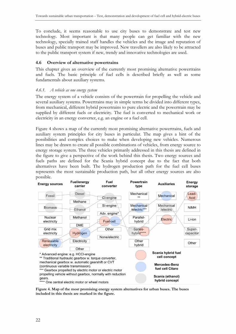
Towards sustainable urban transportation – Test, demonstration and development of fuel cell and hybrid-electric buses
22
To conclude, it seems reasonable to use city buses to demonstrate and test new technology. Most important is that many people can get familiar with the new technology, specially trained staff handles the vehicles and the image and reputation of buses and public transport may be improved. New travellers are also likely to be attracted to the public transport system if new, trendy and innovative technologies are used.
4.6 Overview of alternative powertrains
This chapter gives an overview of the currently most promising alternative powertrains and fuels. The basic principle of fuel cells is described briefly as well as some fundamentals about auxiliary systems.
4.6.1. A vehicle as one energy system The energy system of a vehicle consists of the powertrain for propelling the vehicle and several auxiliary systems. Powertrains may in simple terms be divided into different types, from mechanical, different hybrid powertrains to pure electric and the powertrain may be supplied by different fuels or electricity. The fuel is converted to mechanical work or electricity in an energy converter, e.g. an engine or a fuel cell. Figure 4 shows a map of the currently most promising alternative powertrains, fuels and auxiliary system principles for city buses in particular. The map gives a hint of the possibilities and complex choices to make when developing new vehicles. Numerous lines may be drawn to create all possible combinations of vehicles, from energy source to energy storage system. The three vehicles primarily addressed in this thesis are defined in the figure to give a perspective of the work behind this thesis. Two energy sources and fuels paths are defined for the Scania hybrid concept due to the fact that both alternatives have been built. The hydrogen production path for the fuel cell buses represents the most sustainable production path, but all other energy sources are also possible.
Figure 4. Map of the most promising energy system alternatives for urban buses. The buses included in this thesis are marked in the figure.

4. Background
23
4.6.2. Fuels When discussing fuels some definitions must be made. First, a distinction should be made between fuels from fossil energy sources and fuels based mainly on renewable energy sources, i.e. fossil and renewable fuels respectively. Also, the term alternative fuel is sometimes used, usually referring to all unconventional fuels, i.e. all fuels that are not petrol or diesel. Alternative fuels are therefore not necessarily free from fossil CO2-emissions or not even better than diesel or petrol from a CO2-emission point of view. However, due to the fact that they are alternative, they may be better in terms of energy supply security perspective and sometimes also concerning local emissions. Alternative fuels include for example natural gas, fossil-based synthetic diesel fuels and hydrogen from fossil energy sources. Alternative fuels that also are renewable fuels includes biomass-based ethanol, renewable electricity, hydrogen produced from renewable energy, biogas etc. Sustainable fuels are truly a research topic in itself. The environmental, social and economical aspects of production and the user convenience and economics are critical factors when assessing different fuels. Comprehensive studies comparing different fuels from a well-to-wheel and production volume potential perspective can be found in literature (e.g. Concave et al., 2007; Hamelinck & Faaij, 2006). However, some aspects of hydrogen are discussed in Chapter 6 (acceptance) and Chapter 7 (the hydrogen economy and safety aspects). Some general considerations regarding fuels are mentioned here to complete the picture of alternative powertrains: • Fuels possible to blend into today’s fuels are preferable because they can be
introduced in the transport system in high volumes without other investments than production and distribution capacity of the fuel. The volumes sold of a specific fuel demanding special vehicle adaptations will remain limited until the number of vehicles using the fuel starts to grow. There is a delay in impact when introducing new vehicles due to the fleet renewal and scrapping characteristics. The issue of optimum vehicle fleet conversion has been studied for passenger cars e.g. by Kim et al. (2004). The service life of a city bus may be up to 15 years, which means that all vehicles will use the new fuel after 15 years if introduced at a normal pace in a city bus fleet. Fuels demanding specially adapted engines require investments in development of engine technology and possibly also involve low-volume engine production, at least initially, with high costs for all involved as a result.
• The state of the fuel when stored onboard a vehicle, e.g. liquid or gas. Gaseous fuels are less convenient than liquid fuels as vehicle fuels due to the fact that pressure vessels are needed, which are heavy and bulky. The energy density of gas storage systems is also lower than most liquid fuel storage systems, which means shorter operating range for the vehicle and/or higher energy use due to the extra weight. In addition refuelling of gases is often more time-consuming than refuelling of liquid fuels.
• When it come to internal combustion engine fuels it is important to consider that the Diesel principle (CI, compression ignition engines) is more fuel efficient than the Otto principle (SI, spark ignition engines). Peak efficiency is higher and the efficiency is also higher across a wider operating range in CI engines, whereas SI engines usually have poor efficiency at part load. CI engines are therefore preferable from an energy efficiency point of view. They also have benefits in terms of economy of scale (i.e. mass production) due to the fact that most heavy duty engines are diesel engines. Fuels possible to use in CI engines are therefore generally preferable to fuels that can only be combusted in SI engines.

Towards sustainable urban transportation – Test, demonstration and development of fuel cell and hybrid-electric buses
24
• A fuel should be as convenient for the user as possible, e.g. non-toxic, biodegradable and safe to handle. The ideal fuel may be locally produced from renewable energy sources, but to a specification that is valid world-wide to secure long-term fuel supply and stable fuel prices as well as reasonable cost of vehicles due to high production volumes.
4.6.3. Hybrid powertrains There are three main types of hybrid powertrains: series hybrid, parallel hybrid and power-split (or dual or complex) hybrid. Schematics of the powertrains are shown in Figure 5. A series hybrid powertrain is essentially the same powertrain as in an electric vehicle. Propulsion is handled by one or several electric motor(s). This maximises the potential regenerative electric braking capability due to the fact that the motor can brake electrically, working as a generator, with virtually the same power as for propulsion. This is important in applications dominated by stop-and-go driving, such as city buses. Another big advantage is that the components may be packed freely in the vehicle compared to other powertrains. Also, the operation of the power source is completely independent of the propulsion motor, which allows for running the power source within its optimum operation range. The power source may be any electricity producing unit, e.g. an engine combined with a generator, or a fuel cell system. A disadvantage is the extra energy conversion steps from mechanical work to electricity in the generator and then back to mechanical work again in the motor if the powertrain is equipped with an engine and generator. The parallel hybrid is basically a conventional powertrain to which one or two electrical machines have been added before and/or after the gearbox. The electrical machine(s) and the engine may propel the vehicle separately or in combination. The powertrain is comparatively easy to integrate in most vehicles and has usually lower losses than the series hybrid powertrain due to the possibility of directing energy transmission of mechanical work from the engine via the gearbox, to the wheels. The electrical machine is usually of lower output than in a series hybrid. However, to achieve similar regenerative braking capability as the series hybrid powertrain, the electrical machine must be of similar output as in the series hybrid. The power split hybrid consists of two electrical machines and a combining gear, usually a planetary gear. This type of hybrid may work both in series and parallel modes. The reasons for choosing this type of powertrain include the possibility to operate the engine in its optimum range (similar to in a series hybrid) due to the CVT-type of transmission and at the same time the benefit of the parallel hybrid’s direct mechanical energy flow can be utilised. The most evident example of this type of hybrid is the powertrain in the Toyota Prius passenger car, which was launched 1997 in Japan and a few years later on other markets.
Figure 5. Hybrid powertrain configurations. From left: series hybrid, parallel hybrid and power-split hybrid. ICE=Internal combustion engine, ESS= Energy storage system, G=Generator, M=Motor, EM=Electrical machine (generator/motor), GB= Gearbox, PG=Planetary gear.

4. Background
25
4.6.4. Fuel cells The generally accepted inventor of fuel cells is Sir William Grove, 1839, but the credit for performing the pioneering work that made the technology useful is usually given to General Electric during the U.S. space programme in the 1960s. It is not in the scope of this thesis to describe all details of fuel cells and fuel cell systems, comprehensive information about fuel cells and fuel cell systems may be found in literature (e.g. Carette et al., 2001; Winter & Brodd, 2004; Larminie & Dicks, 2003). However, some fundamental aspects are mentioned here to give an overview. A fuel cell is an electrochemical device in which electricity is generated by redox reactions at the anode and cathode, similar to the reactions in a battery. The main difference between a fuel cell and a battery is that the reactions continue for as long as reactants are supplied to the fuel cell while a battery is a closed system where the reactants are stored in the electrodes and the electrolyte. There are different types of fuel cells with different characteristics concerning chemistry, operating temperature, fuel cell and system design using different fuels. The most common fuel cell for vehicle applications is the hydrogen powered polymer electrolyte fuel cell, usually referred to as PEFC or PEMFC. The main principle of a PEFC cell is shown in Figure 6.
Load
Unreacted H2and
impurities
H2
Air:21% O279% N2
H2O unreacted O2
N2
Anode Cathode
Electrolyte
H+
e-
Figure 6. The fuel cell principle.
A fuel cell stack, in which often hundreds of cells are connected in series, is the heart of a fuel cell system. Other components in the system include: air and fuel supply system, thermal management system, water management system and control system. In addition, a dc/dc converter is usually needed for power conditioning. The efficiency of a fuel cell system depends on the electrochemical efficiency of the fuel cell reaction as well as on the losses in auxiliary components, of which the air compressor, if fitted, usually imposes the highest parasitic load. The main advantages of fuel cells are their high energy conversion efficiency, especially at part load, low noise due to the non-combustion energy conversion process. Also, the modular and simple design (hundred of similar cells stacked together) provides a potential cost advantage when mass-produced. Finally, they have a potential for long service life and low maintenance due to few moving parts. Main drawbacks are high cost at present and low/unproven long-term durability, as well as the lack of a hydrogen infrastructure. In a fuel cell vehicle a series hybrid powertrain configuration is most suitable due to the fact that the fuel cell produces electricity and not mechanical work.
4.6.5. Energy storage systems Different kinds of energy storage systems for hybrid powertrains have been proposed and analysed (e.g. Winter & Brodd, 2004; Van Mierlo et a., 2004; Chu and Braatz, 2002). These include flywheel, hydraulic, pneumatic and electrical storage systems such as

Towards sustainable urban transportation – Test, demonstration and development of fuel cell and hybrid-electric buses
26
supercapacitors and batteries. The demands on the energy storage system depend on the type of powertrain and requirements on the system range from energy to power buffer qualities. This makes different energy storage systems viable in different applications. Some energy storage methods are discussed in Paper VIII. Electric energy storage methods are most viable for hybrid-electric powertrains. The main advantages of supercapacitors are high power density, high charge and discharge efficiency and long potential service life. These advantages are mainly due to the fact that the storage is based on the electrostatic storage principle rather than chemical reactions like in batteries. Batteries on the other hand have superior energy storage capacity but proven battery technologies, e.g. NiMH and lead-acid, have limited power densities and as yet unproven or limited service life in demanding applications.
4.6.6. Auxiliary systems Auxiliary systems contribute to a large share of the energy use in vehicles, especially in low-speed vehicles such as city buses, which is shown in Papers I-IV and discussed in Chapter 5. All systems not contributing to the propulsion of the vehicle are regarded as auxiliary systems in this thesis. These are: power steering (usually hydraulic), cooling fan(s) (on buses usually hydraulic), pneumatic system for air suspension, brakes and doors, air conditioning and heating system, pumps for oil and water and electric systems (24 V systems). The auxiliary systems in conventional vehicles are usually powered by the engine, either via gear transmission or by a belt drive. Apparent is that auxiliary systems use a larger portion of the energy when powertrains are made more fuel efficient. Also, electrical auxiliary systems are more feasible than mechanical systems in electrical powertrains. Auxiliary systems may be improved in different steps, from improved control of conventional systems, electrical powering of conventional systems to completely new systems usually operated electrically and only on demand to avoid unnecessary losses.
4.7 Examples of products and demonstration projects with hybrid and fuel cell buses
Around 50 fuel cell bus models have been developed since the early 1990s. Produced in highest volume (36 vehicle) is the Mercedes-Benz fuel cell Citaro bus, which have been operated in different projects: CUTE (Europe), HyFLEET:CUTE (Europe), ECTOS (Iceland), STEP (Australia) and FCB (China) (HyFLEET:CUTE, 2008). Most other fuel cell buses are test vehicles produced in small series or single examples. An overview of fuel cell bus projects may be found on the internet (Netinform, 2008). North America is so far the main market for hybrid electric buses with hundreds of buses operated in many cities, from Los Angeles in the west to New York in the east. The U.S. National Renewable Energy Laboratory is coordinating the evaluation of most hybrid bus fleets in North America (NREL, 2008). This market has been created by heavy economical incentives.

5. Evaluation of fuel cell buses by tests, vehicle simulation and mapping of energy flows – reflections on Papers I-IV
27
5. Evaluation of fuel cell buses by tests, vehicle simulation and mapping of energy flows – reflections on Papers I-IV
This chapter concludes the main test results and technical findings from the fuel cell bus test and demonstration projects described in the introduction and in the appended Papers I-IV. The main methodologies are described in the methodology chapter.
5.1 Technical descriptions of the buses
The design-purposes of the vehicles differed considerably. Whereas the Scania bus was designed and built as a one-off working example to study the potential of fuel cell hybrid vehicles with electric auxiliaries during limited tests, the Mercedes bus was designed to be economical to produce and economical and robust enough to be operated and demonstrated for several years in commercial operation. Consequently, the technical solutions are technically more sophisticated and energy efficient, but also more costly and less robust in the Scania bus, whereas the design is more simple, cost-effective and robust but not very energy-efficient in the Mercedes bus. The Scania fuel cell hybrid concept bus was a medium-sized 9 m city bus with a 50 kW PEFC system and a lead-acid battery pack powering a series hybrid powertrain with wheel hub motors (150 kW in total) and electrically powered auxiliary systems. The Mercedes-Benz fuel cell Citaro bus was a full-size 12 m city bus with a >250 kW PEFC system powering a central electric motor powering a conventional automatic gearbox as well as conventional mechanical auxiliaries via a special gear-case. Technical details of the buses may be found in Figure 7 and Papers I-IV. In addition, the Scania bus is described in a paper by Overgaard & Karch (2001).
The Mercedes-Benz Citaro fuel cell bus
IV.
II. III.VIII.
VI.V.
VII.
I.
Figure 7. Packaging and main powertrain components in the Scania hybrid fuel cell concept bus (left) and the Mercedes-Benz fuel cell Citaro (right).
1. Hydrogen vessels 2. Fuel cell system 3. Radiators and fans 4. Hybrid battery module 5. High-voltage power distribution
box 6. Power electronics 7. Wheel-hub motor 8. Dc/dc converter 600/24 V 9. Air compressor and hydraulic
pump
I. Hydrogen vessels II. Fuel cell stacks
III. Radiators and fans IV. Fuel cell system components V. Central electric motor
VI. Automatic gearbox VII. Auxiliary gearcase
VIII. Air conditioning

Towards sustainable urban transportation – Test, demonstration and development of fuel cell and hybrid-electric buses
28
The fuel cell systems in both buses are so-called dead-end systems with purging on the anode (i.e. hydrogen) side of the cells. Purging means that small quantities of hydrogen are ventilated from the stacks from time to time to avoid accumulation of impurities and water at the anode. Purging is a standard procedure for PEM fuel cell system. The amount of hydrogen lost in this way was usually less than 5% for both systems. Both fuel cell systems are also pressurised on the cathode side. Air is injected into the stacks with twin-screw oil-free air compressors, in the Scania bus directly electrically driven and in the Mercedes bus driven mechanically by the auxiliary gearcase. Apart from these similarities the fuel cell stack and system designs, including thermal and water management differ considerably between the buses. In the Nuvera stacks in the Scania bus the assembly components are metallic and water is directly injected on the cathode side of the cells both for cooling and humidifying purposes. This means that reactant gases do not need to be humidified, nor are separate cooling liquid channels necessary in the stacks. The cathode exhausts (air, water and steam) are cooled and water condensed (for injection in the stacks) in a heat-exchanger with a secondary cooling loop. The use of metallic bipolar plates simplifies production. Overall, this approach brings cost-effective stack design and a less complex and more compact system. However, the system is hard to control, with risks for water clogging in the gas channels as well as local water deficiency, both with lower performance, possible hotspots and accelerated MEA-degradation17 as a result. The approach chosen by Ballard (in the Mercedes buses) ought to be easier to control and thereby possibly more robust. Here, the bipolar plates are made of a graphite/composite, reactant gases are pre-humidified and coolant flows in separate cooling channels in the stacks to dissipate heat from the stacks. The design of the auxiliary components with separate electric motors, one for powering the hydraulic pump for the power steering and one for the air compressor for the pneumatic system, as well as a dc/dc converter (600/24 V) for 24 V power supply made energy mapping rather easy in the Scania bus. Measuring voltage and current for defined components are much easier than measuring torque and speed of the auxiliary components powered mechanically. In the Mercedes buses some of the auxiliaries were measured and reported directly in test data from Ballard’s data acquisition system or calculated by Ballard while others had to be characterised indirectly in separate tests. In the separate tests, the bus was stationary while the load was varied, typically as a function of motor speed. Such separate tests were performed to emulate power drawn for powering the air conditioning system, the air compressor and thus the energy use for door openings and kneeling and the 24 V systems, including mechanical power drawn by the generators.
5.2 Tests and operation with the Scania hybrid fuel cell bus
Several duty cycle tests were performed with the bus, including Braunschweig, FTP 75, ECE15 as well as specially constructed duty cycles. All tests were performed on flat roads at the Idiada18 proving ground in Spain. The energy use was in the range of 23-26 L/100 km (diesel equivalents19) with the vehicle loaded to 12.5 tonnes. When analysing the energy flows during the tests it was concluded that 24-28% energy was saved thanks to regenerative braking and with a cycle efficiency of the lead-acid battery energy storage 17 MEA = Membrane Electrode Assembly, i.e. the thin anode, electrolyte and cathode that is assembled in one part and connected in series by bipolar plates. 18 See www.idiada.com 19 Energy use (or fuel consumption) calculated in diesel equivalents with the assumptions: LHVhydrogen=120 MJ/kg; LHVdiesel=42.5 MJ/kg; ρdiesel=0.85 kg/L.

5. Evaluation of fuel cell buses by tests, vehicle simulation and mapping of energy flows – reflections on Papers I-IV
29
system of approximately 85%. The average power to auxiliary systems (without air conditioning) was approximately 3-4 kW, which represents 7% of the total energy (i.e. fuel) input or 17% of the produced consumed electric energy. The approximate average energy distribution were: 24 V supply (30%), cooling fans (30%), air compressor for pneumatics (20%), hydraulic steering (15%) and water pumps (5%). An air conditioning unit would have contributed with an extra load of up to 15 kW (e.g. Paper IV) and in this case auxiliaries would correspond to up to half the energy use. The auxiliary systems were further investigated in another study (Andersson et al., 2003; Andersson, 2004). An example of a complete energy mapping for a duty cycle is given in Paper I. External noise was measured following the European council directive 70/157/EEC. The noise levels stated in dB(A) were very low on the fuel cell bus (70.3), compared to regulations (78-80, depending on engine power), and to a conventional low-floor Scania OmniCity bus from 2002 (77). Basically all noise at the fuel cell bus test, when acceleration from 50 km/h, was subjectively perceived as coming from the tires. Observed during the whole test period was also that noise from different auxiliary systems, e.g. fans, compressor and hydraulic pump could be distinguished from other noise sources in the bus. Consequently, when one dominating noise source disappears (e.g. a diesel engine) others become annoying and must be controlled. Also, some of the auxiliary systems were powered electrically at constant operation speed, which creates noise with a narrow frequency band, which is perceived as more annoying than noise with a broader frequency band. The fuel cell system in the bus did not fully perform according to the specifications during the test phase. The fuel cell stack design in the bus was from 1997/1998 and Nuvera Fuel Cells’ (formerly De Nora) first attempt to design and build stacks in this power range. The fuel cell system integration was made by the French company Air Liquide and it was also their first attempt to design a high-power fuel cell system for a vehicle. This may, together with months of delays in the project, during which the stacks were stored improperly, be the cause of internal corrosion and probably MEA-degradation. In the fuel cells, single cells had unstable cell voltages, which limited the performance and power output during the specific fuel cell test. This, combined with the fact that the test facility was not equipped with a power dump for variable high-power electrical loads, meant that the specific tests of the fuel cell system could only be performed on low, constant power, up to 12-13 kW, whereas the design-power was 50 kW. Test results and simulated efficiency curves are shown in Figure 8.
0 5 10 15 20 25 30 35 40 45 500
10
20
30
40
50
60
70
η (L
HV
)
P [kW]
FC StackFC System
Figure 8. Measured and simulated fuel cell efficiency in the Scania fuel cell hybrid bus.

Towards sustainable urban transportation – Test, demonstration and development of fuel cell and hybrid-electric buses
30
5.3 Operation results with the Mercedes-Benz fuel cell bus in the CUTE project
The 27 fuel cell buses in the CUTE project covered in total around 850,000 km or on average slightly more than 30,000 km per vehicle. Most cities operated their buses around 100,000 km, Stuttgart as much as 129,283 km while Barcelona only operated their fuel cell buses 37,654 km. Part of the explanation for the poor operational results in Barcelona was that the fuel production facility broke down and the fuel storage vessels on the buses were contaminated during a hydrogen-compressor breakdown and had to be sent away for three month for cleaning and inspection. The reported availability20 of the fuel cell buses was generally high, but also considerably varying, with 60% reported availability in Barcelona and 99% in Stuttgart. Different aspects of reliability were monitored during the project: number of technical incidents per 1000 km and number of road-calls when the bus had to be towed back to the workshop per 1000 km. As could be expected, the reliability increased during the project, from 16 to 2.5 incidents and from 5 to 0.5 road-calls when the bus was towed to the workshop per 1000 km. Not all road-calls were breakdowns, however. Buses were sometimes towed back when a red alarm somehow was activated. The warning system of the bus was adjusted during the project towards fewer events causing red alarms as the technology gradually was proven. This gradual release of the safety system might be one reason for the relatively few major breakdowns of systems and components in the project and in consequence an explanation to the positive attitude and confidence in the buses from drivers and operators as found in Papers V-VI. It is likely that a driver reacts more negatively to a real breakdown than to a few false alarms, especially if they know that they depend on initial precautions. The buses were parked in the workshop or outdoor connected to a ramp during wintertime in Stockholm. An electric heater provided heat so that the fuel cell stack temperature never dropped below +5 °C, since freezing temperatures would risk damaging the stacks. This worked well except for a few occasions on cold winter nights. Some redesign (re-routing of heating loop and adding of insulation) of water pipes was also made after some initial problems with frozen water pipes during the first winter months. Starting problems occurred in cold weather both in Stockholm and in other cities because the 24 V batteries got depleted. The main technical problem was that the first generation of inverters broke down after some time in operation. This happened at the same time in many cities and there were only a few spare systems in stock. Therefore, some buses were out of service for some weeks in several cities until the problems were solved. Some problems were also related to the fact that cell voltage monitoring boards in the fuel cell stack modules did not cope well with humidity, but very few problems were related to the fuel cell technology itself. Actually, most stacks operated for up to 3,000 hours or more, which was above expectations.
5.4 Test-based fuel economy analysis of the buses in CUTE
The average fuel consumption varied a great deal between cities, from 20.4 kg H2/100 km in Hamburg to 30.0 kg H2/100 km in Porto. This corresponds to 68-100 L diesel equivalents per 100 km, which is considerably higher than for conventional city buses of similar size. It should, however, be noted again that the buses were designed for
20 Availability was in the CUTE project defined as performed (days in) operation divided with planned (days in) operation.

5. Evaluation of fuel cell buses by tests, vehicle simulation and mapping of energy flows – reflections on Papers I-IV
31
reliability and ease of maintenance and not primarily for fuel economy. Also, these figures are valid for the whole project period, including fuel consumed during maintenance and tests etcetera. Therefore they do not fully represent the fuel economy in real-life operation on bus routes. The actual fuel consumption on bus routes was generally lower. Good fuel economy is crucial for vehicles to be competitive in the future with higher energy and fuel costs and increasing concerns for environmental issues related to the use of energy and fuels. An important and frequently recurring aspect influencing the energy analysis result is the so-called power dump function of the fuel cell system. This means that a minimum current is always drawn from the fuel cells in operation, representing approximately 30 kW output power from the fuel cell system. The function was implemented to increase the service life of the fuel cell stacks, since it is favourable for the stacks if they are operated with a constant gas-flow. When the power produced by the fuel cell cannot be utilised anywhere in the vehicle, the excess power is consumed, or dumped, in a heat resistor in the cooling system. This is a choice in the design of the stacks and the fuel delivery system and not a limitation of PEM fuel cells in general. Even though the minimum current limitation is beneficial for the service life of the stacks it counteracts one of the main advantages with fuel cells in urban vehicles; namely the high efficiency at low load. Also, the power dump contributes to unwanted fuel consumption during coasting or braking, when a normal engine shuts of the fuel injection. Indeed, the minimum current requirement was in general the reason for twice as high hydrogen losses than for the hydrogen purging, i.e. 10% compared to 4-5%. A complete energy mapping approach was chosen also when evaluating the buses in the CUTE project. The representation of energy flows as complete energy mapping diagrams, so called Sankey-diagrams is not new, but for some reason seldom found in literature (e.g. Ahluwalia et al., 2005). Sankey representation gives a clear overview of the energy flows, enabling optimisation potentials to be identified on a complete system level. It is therefore a useful first tool for allocating resources for exploring and developing potential areas for improvement and may also be used for validating and evaluating improvements, the latter described in Paper IV. The evaluation for pointing out and quantifying the potential for fuel economy improvements and to assess factors influencing on the fuel economy was performed using different methods. None of the methods used gave complete answers and the results sometimes differed slightly. Thus, the results should be interpreted together. The main methods used were: • Specific tests for characterising particular systems. • Duty cycle tests in different cities. • An empirical simulation model to identify and explore potential improvements. Auxiliary systems were tested in order to get a general view of the auxiliary systems’ energy use and to gather performance characteristics of different systems as input to the simulation model. In general, around 25% of the energy content in the fuel or approximately the same amount of energy that is used to propel the bus was used to power auxiliary systems. This is a much higher average power than in the Scania fuel cell bus with electrically powered auxiliaries. The auxiliary systems consuming most power are the air conditioning system when in use, the supercharger for fuel cell air supply and the alternators for 24 V supply. Roll-out tests were performed to quantifying the unknown parameters in the equation for total running resistance of the vehicle, i.e. the rolling resistance coefficient and

Towards sustainable urban transportation – Test, demonstration and development of fuel cell and hybrid-electric buses
32
aerodynamic drag coefficient. An important observation is that the rolling resistance, which consists of the rolling resistance coefficient and the vehicle weight, is the completely dominating running resistance factor at the normal operating speeds (0-50 km/h) of a city bus. Effort should therefore be made to reduce the rolling resistance and weight of the bus whereas the aerodynamics are less important. The impact of changing vehicle weight as well as the rolling resistance coefficient was examined using the simulation model for the bus on bus route 66 in Stockholm. The fuel penalty per extra tonne was found to be around 3.2% with the minimum current requirement included and 3.7% without it. The latter is in line with results from UITP stating that an extra tonne in city driving involves a fuel penalty of 3.8% (UITP, 2004). The minimum current requirement reduces the potential benefit also for other improvements due to the fact that 30 kW are constantly produced by the fuel cells and this power has to be consumed. Consequently, improvements that periodically reduce the power demand of the bus to below 30 kW will result in an increased power dump of the same magnitude. Duty cycle tests were performed in five cities to study how different factors affect the fuel consumption. These tests showed a clear dependence between fuel consumption and average speed as well as the number of stops per kilometre. More stops and lower average speed gives higher fuel consumption. This could also be noted within cities during rush hours with more crowded traffic and lower average speed. The results are in line with general statements on fuel consumption for city buses depending on speed and stops by UITP, but fuel consumption levels are approximately 50% higher (UITP, 2004). Topography was not found to have any relevant influence on the fuel economy. Another way to analyse the duty cycle tests was to separate the time spent and energy consumed in drive modes. The drive modes were: idling, deceleration, acceleration and cruising. It was found that the buses in cities with many stops per kilometre and low average speed spend approximately 35% of the time and 20% of the fuel idling. Around half of this energy is due to the minimum current requirement. It was also evident that around 10% of the fuel was spent during deceleration. Also here the minimum current requirement is part of the explanation. In a conventional bus with internal combustion engine the fuel injection would shut off during most of the deceleration and less energy would be spent in this mode. Not surprisingly, most fuel, 35-55% was spent accelerating. The time and fuel spent in different power ranges was also analysed. More time and energy was spent in higher power regions for cities with higher average speeds than in cities with lower speeds. The fuel consumption during wintertime in Stockholm was higher than during summertime. In cold weather, the heat from the fuel cell system was insufficient to heat the passenger compartment and therefore a special heating resistor was used to heat up the cooling liquid. In such conditions, the losses in the dump resistor were very low, or neglible due to the fact that the special heating resistor consumed sufficient power to keep the minimum current in the fuel cells.
5.5 Vehicle modelling-based fuel economy analysis of the buses in CUTE
The use of simulation tools is a cost-effective way of testing alternative design solutions. A main benefit is that design changes can be tested without external disturbances influencing the results. This means that the results can be obtained repeatedly. In addition, the interaction between several changes in a design can be assessed. In this case

5. Evaluation of fuel cell buses by tests, vehicle simulation and mapping of energy flows – reflections on Papers I-IV
33
the model was used for defining and exploring the potentials of energy-efficiency improvements and for validating some of the results based on actual tests of the buses. The purpose of a simulation study defines the accuracy demand on the simulation results and this in turn defines the demands on quality of in-data and on algorithms in the model. The study discussed here is a fairly rough relative study. The simulation model, described in Paper IV, was developed in the Matlab-Simlink-based program CAPSim. The model is quasi-static and semi-empirical, based on measured data and validated against other measured data than the data it was developed from. Simulations were made on bus route 66 in Stockholm: first a base-case simulation with the original bus and then with different improvements implemented in the bus model. The resulting energy flow diagrams from the base-case simulation and from the simulation with all improvements integrated are shown in Figure 9. The potential improvements, defined and integrated into the model were: • Replacement of the alternators with a dc/dc converter with approximated and
constant efficiency of 95% saves approximately 5% fuel and even more if the minimum current requirement could be lowered.
• Reduced vehicle weight by 2000 kg. The conclusion from this is that every extra tonne contributes to 3.2-3.7% higher fuel consumption, the higher value applying when the minimum current requirement was removed.
• Removal of the minimum current requirement saves around 15% of fuel. • Reducing the rolling resistance coefficient by 25% saves around 2% fuel. More
kinetic energy has to be removed in the brakes or retarder compared to the original bus or in the case when the weight is reduced, since it cannot be fully utilised as regenerative energy for powering auxiliary systems.
• The four improvements implemented at the same time gives a 30% reduction of fuel consumption. A larger portion of energy has to be disposed of by braking, which implies that hybridisation would be beneficial.
Figure 9. Sankey diagram showing the average energy flows in the bus for the reference simulation (upper) and the simulation with all improvements integrated (below) on Route 66 in Stockholm. Relative share (in %) of total energy input, i.e. fuel input, is also shown.

Towards sustainable urban transportation – Test, demonstration and development of fuel cell and hybrid-electric buses
34
Reflections on the results from the simulation study: • The high energy use of the compressor (15-25% of the fuel cell power) for air supply
to the fuel cell system makes system designs operated closer to ambient pressure an interesting alternative (UTC, 2008). On the other hand, the power density is typically lower in ambient pressure systems, which implies that the complete system will be heavier. This is not acceptable in the current bus design.
• Important to consider in energy systems involving many energy conversion steps is that the importance of an extra load increases further down the energy chain. For example: a 100 W 24 V load contributes to 4.5 times this power, 450 W, in fuel if the 24 V power is produced by the alternators, taking the efficiencies of the fuel cell system, the inverter and motor, the auxiliary gearbox belt drive and finally the alternators into account. The same fuel-to-power factor is 2.1 if the 24 V power is produced by the proposed dc/dc converter. Consequently, even small reductions in power drain might be worth considering and on the contrary, adding even a small extra load should be reconsidered, if possible.
• Operation of auxiliaries via the special gearcase makes their operation a function of vehicle speed and gear engaged. The higher rotational speed of the gearcase, the higher the losses. An optimal solution would be to operate all auxiliaries independently and when needed, i.e. on demand.
• The gearbox contributes to considerable losses, actually of the same magnitude as the rolling resistance. A more fuel efficient design would be to let an electric motor propel the rear axle directly, or via reduction gears. This implies, however, that the auxiliaries must be powered differently than in the current design.
Hybridisation would entail several advantages, which may be discussed even though it was not simulated. In a hybrid powertrain the fuel cell system could be operated slightly less transiently and generally at lower loads, which means that the average efficiency would be slightly higher. It would also enable downsizing of the fuel cell system. This has advantages related to system cost and weight but is somewhat inferior on efficiency due to the fact that the relative power load of the fuel cell becomes higher. The latter is also observed in previous studies (e.g. Ahluwalia et al., 2005). The most extreme downsizing would be a plug-in hybrid, i.e. a hybrid with a large energy storage system and a fuel cell as range-extender. Hybridisation could also be part of the solution for mitigating the minimum current requirement if it cannot be avoided differently. The ideal fuel consumption reduction potential due to regenerative braking is up to 27%.

6. Acceptance of hydrogen and fuel cells and recommendations for future demonstration projects – … Papers V-VI
35
6. Acceptance of hydrogen and fuel cells and recommendations for future demonstration projects – reflections on Papers V-VI 6.1 Background to public acceptance
New technologies like hydrogen fuelled fuel cells will contribute significantly to a more sustainable energy system only if they are produced and used in large numbers, i.e. they must be commercially viable and compete on the market with other technical solutions. In order to do this they must be accepted by potential customers and the public. Acceptance includes obvious factors like value for money compared to competing solutions and that the performance is according to customers’ needs, demands and expectations. Very important is also that a technology is perceived as safe, especially when it comes to a new fuel like hydrogen (this subject is discussed in Chapter 7). Acceptance for new bus technologies includes several stakeholders and aspects. The ultimate goal is obviously to make passengers prefer travelling by bus to travelling by car in order to increase the share of public transport. Bus drivers play a very important role as they are in the frontline meeting the new technology as well as the public. Consequently, establishing acceptance among bus drivers is a main goal to build a wider acceptance for the technology. If bus drivers are confident and positive to the technology the chances are good that the passengers get a positive experience too. In Stockholm, when a rather primitive generation of hybrid buses was tested in the 1990s there was a saying among the drivers that translated to English reads “the hybrid bus that came to stay (or stop)”. Unfortunately the saying did not mean that it was a promising technology that was here to stay because it was so good but implied instead that the buses were unreliable and stopped frequently when operated. Eventually, very few drivers wanted to drive the buses. One reason was of course that the technology was immature and unreliable. Another reason may have been that the organisation and demonstration project failed to motivate the drivers and to build confidence for the buses and the project among them. The participants in the CUTE project in Stockholm point out the CUTE-project as an exemplary project in terms of public acceptance and acceptance among bus drivers. This is supported also by the survey results among passengers presented in Paper V and VI. A number of studies focusing on the attitudes to and willingness to pay extra fees for hydrogen-powered vehicles have been published recently. An overview of such studies published until 2003 are presented in the AcceptH2 study: Analysis and comparison of existing studies (Altmann et al., 2003). Studies in Germany and Great Britain in the 1990s and early 2000s showed that people associate hydrogen with anything from visions of environmental friendliness to explosion risks. Another conclusion from these studies was that even though people respect and support the idea of environmental friendliness, they were not ready to pay extra for environmentally friendly technologies. Instead, price and other performance factors than environmental performance where key decision factors when purchasing vehicles (Altmann et al., 2003). However, other studies show a rather high willingness to pay (e.g. O’garra et al., 2007). Recent studies (e.g. Zachariah et al., 2005; O’Garra et al., 2005) conclude that, contrary to expectations, the public attitude towards hydrogen is not a critical factor for the introduction of hydrogen as a vehicle fuel. Even though the knowledge is low, the safety concerns are few and the acceptance high. However, most of these studies concern only the public awareness and were performed among people with no experience of hydrogen and fuel cell vehicles.

Towards sustainable urban transportation – Test, demonstration and development of fuel cell and hybrid-electric buses
36
A study in the Netherlands concludes that public acceptance is easily influenced by negative information (Zachariah-Wolff & Hemmes, 2006). It is also suggested that objective information about the technology may reduce this vulnerability. This is in line with conclusions presented in another study (Schulte et al., 2004). They found that the perceived satisfaction, risk and attitude towards a technology are strongly dependent on the individual and his or her experience, interest and social background. Experience and interest may be influenced to a varying extent by three factors: 1) education, 2) marketing and 3) exposure to a technology. This supports the idea of providing neutral information to the public as well as emphasises the benefits with early demonstration project where people get the chance to get familiar with a new technology. Therefore, for a successful introduction it is probably crucial that the people handling the vehicles on a daily basis, the drivers and operators, are satisfied with the technology. They are ambassadors for the new technology in the case of a bus demonstration project. Attitudes among bus drivers, with experience of fuel cell buses, have previously to some extent been discussed in literature (XCELLSIS, 2007; Maack et al., 2004; CUTE, 2006).
6.2 Scope of presented studies of public acceptance
A common attitude survey was not performed in the scope of the CUTE project. However, several participating cities in CUTE and also Reykjavik (in the partner project ECTOS) performed attitude studies themselves. Paper V in this thesis presents the results from surveys of the attitude towards hydrogen fuel cell buses among passengers and bus drivers performed in Stockholm during the autumn of 2004. Paper VI aims to present a complete picture of attitudes towards the fuel cell buses in the CUTE project, i.e. among passengers, drivers and operators who have been exposed to the new technology. The main results, presented in the next subchapters include the following:
• Results from the two surveys among passengers in Stockholm and reflection on how the attitudes in Stockholm changed over one year of operation of the buses. A statistical analysis of the results is described in Paper VI.
• Results from a driver survey, initiated by the CUTE project partners in Luxembourg, and analysed by the authors in Paper VI. The analysis includes answers from the four cities: Luxembourg, London, Hamburg and Stockholm of which the results for Stockholm were also presented in Paper V.
• Results from a qualitative survey performed at the end of the project among the bus operators and local project coordinators, to recapitulate the main successes and problems of the project.
• Finally, the experiences and recommendations from the seven cities in the CUTE project are discussed. To avoid subjective interpretations most answers are presented as quotes, just like in Paper VI.
6.3 Results from the Stockholm surveys among passengers
The following factors were included in the questionnaire, which comprised slightly more than 500 respondents on both occasions:
• General information (i.e. gender, age and travel patterns). • Knowledge about the current fuel cell bus project, and interest in learning more
about hydrogen and fuel cell technology. • Attitude towards the performance of the bus (comfort and noise levels)
compared to conventional buses, and safety aspects of hydrogen and fuel cell technology in the buses.

6. Acceptance of hydrogen and fuel cells and recommendations for future demonstration projects – … Papers V-VI
37
• Willingness to pay a higher fee to enable more fuel cell buses in urban revenue service.
• Key factors affecting the choice of transport mode. The respondents in both surveys were older than the normal daily commuter and also than the average population in Stockholm. Also, there were more daily or frequent commuters among the respondents than the average in Stockholm and also a larger proportion women than normal for commuters in Stockholm. Since the respondents profile differs from that of the regular traveller in the Stockholm public transport system, applying the interpretation of the results to the general commuter should be done with care. The results concerning perceived safety, comfort and noise did not change statistically between the surveys. Slightly more than 60% agreed that the comfort level was better on the fuel cell buses and around 75% that the noise levels of the buses were lower than on normal buses. The willingness to pay a higher ticket price for hydrogen did not change between the surveys. Only 20-23% of the respondents were interested in paying extra for having more fuel cell buses in the Stockholm traffic, whereas 61-68% were negative to paying more for fuel cell bus traffic. The willingness to pay is much lower than that presented in other studies (e.g. O’garra et al., 2007). Part of the explanation may be how the question was asked, but also the current ticket prices, which were higher in Stockholm than in the cities in the study quoted. Passengers rated safety, punctuality and frequency as the most important factors when choosing transport modes. Environmental aspects and comfort were also rated as important, but not to the same extent, which conforms to results found in literature (e.g. Altmann, 2004). Female passengers value environment and safety higher than men. This implies that in daily life for the majority of people, smooth commuting and financial aspects are most important. In view of this, it is doubtful whether buses should be used for tests and demonstration of new (and often expensive) technology. It could be argued that this money would be better spent on investment to improvement the public transport system in terms of safety, punctuality and frequency. On the other hand there are good arguments for using city buses as pioneering vehicles as discussed in Chapter 4.5.
6.4 Results from the surveys among drivers
In total, about 200 drivers (in Luxembourg, Stockholm, London and Hamburg), of which 75% were from Luxembourg, participated in the study that was organised by The City of Luxembourg. Of these, 23 questionnaires were answered by drivers in Stockholm. Most drivers in all cities rated smell and pollution as less disturbing than for regular buses, and a majority also considered the comfort for the passengers as equal or better. Also the answers about perceived safety was similar, 95% and 98% viewed the safety as equal or better than for normal buses in Stockholm and the other cities, respectively. Almost 60% of the drivers in Stockholm experienced the braking performance as inferior to normal buses. Comments were made of an unwanted retarder delay and also that the retarder was engaged too abruptly when finally engaged. The drivers in Stockholm were much more pleased with the acceleration and speed performance of the buses than the drivers in the other cities. An explanation for this

Towards sustainable urban transportation – Test, demonstration and development of fuel cell and hybrid-electric buses
38
might be that the average speed of the buses in Stockholm was lower than in the other cities, putting lower demands on high-speed acceleration. Furthermore, the drivers in Stockholm thought that driving the fuel cell buses was more exhausting than the drivers in the other cities. One example was that the steering wheel was heavy to work, which may be explained by a combination of factors. The fuel cell buses were operated on one of the most winding bus routes in Stockholm, the steering wheel in the buses was smaller than on the buses normally operated in Stockholm and finally the front axle weight on the fuel cell buses was higher than on conventional buses, but the power-steering system was not adapted to this. It should be noted that the drivers’ opinions were subjective comparisons with the buses they normal drive.
6.5 Recommendations for future demonstration projects
This survey was designed with open-ended questions and is thereby qualitative by its nature. The operators’ experiences and recommendations are displayed as quotations in Paper VI as a subjective way of showing the results. The main results include: • The main benefits of the trial with fuel cell buses mentioned were the public
demonstration of the buses (4 out of 7 mentioned this) and the experience gained concerning the new fuel and technology (4). However, two operators also mentioned the benefits for the company in terms of promotional aspects and image.
• Main technical problems mentioned where inverter failures in combination with lack of spare parts (2). It is apparent that they accepted that it was a demonstration project with pre-commercial vehicles and hence both expected and accepted some initial problems. Some operators, however, mentioned the extra planning and care needed for the fuel cell buses as an initial problem.
• When it comes to lessons learned for the next project the bus operators gave varying answers, including:
“Have a better economic back up for unknown expenses. The project has been much more expensive than initially planned.” “Have a stock of the most used spare parts or systems to replace in a shorter time…” “Become involved earlier in the set up to influence the decision making process…” “Next time [the operator] will do this project we train only the drivers of one line…”
• Answers to the question “What would you expect differently from your bus supplier next time?” were more consistent: Increased availability of spare parts (2) and increased information sharing (3). Three cities were disappointed with the level of transparency concerning information and were of the opinion that they did not receive sufficient information. In addition, one city was disappointed with the additional costs of items or investments not included in the project plan from the start and also requested better local participation and support from the bus supplier for dissemination activities. A technical comment was made on the warning system in the bus by one bus operator. This operator asked for the buses to be fail-safe so that the drivers’ action cannot damage the bus: “A vehicle with a shut down system when a red warning light incident occurs. We cannot rely on drivers observing warnings to stop as they should do. We cannot afford as a business, the financial impact of damage sustained to vehicle equipment when an individual chooses to act contrary to their training…”

6. Acceptance of hydrogen and fuel cells and recommendations for future demonstration projects – … Papers V-VI
39
One city gave recommendations for participants in similar projects: – “Make sure to work with motivated drivers and make sure to keep the drivers
informed and updated about the progress of the project – they are the greatest ambassadors!”
– “Plan for how to take care of study visits and media.” – “Make sure to establish a dissemination and communication plan accepted by all
partners.” – “Create routines for collection of any un-normal happenings, near misses and
incidents.” – “Start with low expectations on the availability of the bus and increase the bus
operation hours gradually when you see what the technology can perform.” A key outcome of the survey was that the project was successful and that the buses were more reliable and had better availability than the operators expected from the start. It seems like the transport authorities and operators in most cities learnt a lot, not only about the fuel cell technology and hydrogen, but also about operating new technology on a large scale. This ought to make things like planning and budgeting easier and more straightforward next time. For example, Stockholm is looking very much into the experiences from the CUTE-project when planning for their fleet of ethanol-hybrid buses that will start operating during 2008.

Towards sustainable urban transportation – Test, demonstration and development of fuel cell and hybrid-electric buses
40

7. Considerations related to the vision of a hydrogen economy – reflections on Papers VII-VIII
41
7. Considerations related to the vision of a hydrogen economy – reflections on Papers VII-VIII
Two aspects related to the hydrogen economy are discussed in this chapter, based on Paper VII and VIII. The first is hydrogen safety and the other is the performance of hydrogen and fuel cell based systems compared to alternative systems. However, to give a background the first sub-chapter is dedicated to the so-called hydrogen economy, an utopia or vision that according to some might save the world or at least play an important role in the creation of a sustainable energy system.
7.1 The vision of a hydrogen economy
The vision, or according to some critics, the utopia of an energy system fully or partly based on hydrogen as energy carrier is called the hydrogen economy, or hydrogen society. The idea of a “hydrogen economy” was presented already in 1974. Hydrogen should be produced from nuclear power to smoothen and increase the nuclear power production during off-peak hours (Rose, 1974). Later, the vision was broadened, or redefined, and has in its new shape been adopted by a considerably number of stakeholders and countries world-wide (e.g. European Commission, 2003; US DOE, 2002; Árnason, 2000). This hydrogen vision is much described, promoted and discussed in literature (e.g. Ogden, 2002; Dunn, 2002, Midilli et al., 2005a; Lovins, 2003). Hydrogen as energy carrier, preferably produced from renewable energy sources and in combination with fuel cells for the energy conversion to electricity (and heat), will facilitate the continuation of the development from solid to gaseous fuels (wood – coal – oil – CNG – H2) and simultaneously towards a higher hydrogen-to-carbon ratio in fuels (e.g. Dunn, 2002). The use of hydrogen and fuel cells is claimed to be part of the solution to current and upcoming challenges that the energy sector in general and the road transport sector in particular are facing regarding: • An affordable long-term energy (i.e. fuel) supply. This is because hydrogen can be
produced from virtually any energy source: fossil, renewable or nuclear based. Hydrogen is suggested as an energy buffer in energy systems with large amounts of intermittent energy production, e.g. wind and solar power.
• Greenhouse gas emissions (mainly CO2) and climate change. Producing hydrogen from renewable energy sources or even nuclear power have the potential of very low, if any, emissions of fossil CO2.
• Health and life quality issues for people in urban areas caused by pollution and vehicle related noise. Fuel cells running on hydrogen produce no other tailpipe emission than water/steam and operate very silently.
It has also been suggested that a transition to a hydrogen economy should improve the levels of global peace and stability because it reduces the dependence on fossil fuels (e.g. Midilli et al., 2005b). Besides in fuel cells, hydrogen can be used as a fuel in internal combustion engines (e.g. Karim, 2003; Sierens & Verhelst, 2001), pure with the potential of 20-25% higher efficiency than comparable petrol engines (Ogden, 2002) or in blends e.g. with biogas or natural gas. Commercial vehicle manufacturer MAN has developed hydrogen fuelled buses with spark-ignition engines (e.g. Knorr et al., 1998, Hipp et al., 2003, HyFLEET:CUTE, 2008). Combustion of pure hydrogen will cause some emissions of NOX and also noise and, if blended e.g. with CNG, normal emissions caused by the complete and incomplete combustion of hydrocarbons will also occur (e.g. CO, CO2, HC).

Towards sustainable urban transportation – Test, demonstration and development of fuel cell and hybrid-electric buses
42
It is clearly not certain that hydrogen and fuel cells are the mass transport technology of the future even though they in several respects have a good theoretical potential to contribute to a sustainable transport system. For example Shinnar (2003) presents severe criticism towards the vision of a hydrogen economy, ranging from objections about poor overall energy efficiency to safety. Bossel (e.g. 2004, 2006) objects mostly to the poor energy efficiency of hydrogen energy systems and proposes the use of electricity as energy carrier. A critical comparison of hydrogen versus alternatives can be found in Paper VIII, which is discussed in Chapter 7.3. The expectations on hydrogen and fuel cells were particularly strong around year 2000. Basically all car manufacturers, including General Motors, Ford, Toyota, DaimlerChrysler and Honda, had fuel cell concept cars for demonstration and tests in the late 1990s and early 2000s, with claims on commercialisation of fuel cell vehicles around 2005. DaimlerChrysler claimed 1999 that they would have a limited production of 5,000-10,000 fuel cell vehicles by model year 2004 (Renzi & Crawford, 2000). MAN claimed somewhat more cautiously in 2000 that the first deployment of pre-series fuel cell buses could be expected from 2005 (Schaller & Gruber, 2000). Also, it was estimated in 2003 that there would be 2,000 hydrogen fuel stations in Europe by 2008, 6,000 by 2010 and that the market would be fully developed by 2014 with around 12,000 hydrogen fuel stations (Geiger, 2003). Most major oil companies, including BP, Shell, ChevronTexaco and ExxonMobile, participated or participate in hydrogen demonstration programmes. Today it is evident that the development was not that quick and nowadays there is a somewhat reluctant or maybe balanced view on hydrogen and fuel cells. A lot of problems remain to be solved related to cost and technical challenges for developing a fuel infrastructure as well as the fuel cells and hybrid-electric powertrains. However, the vision still exists, and most vehicle manufactures believe that hydrogen fuelled fuel cell vehicles will play a role in the future transportation system, but forecasts and promises about future product launches and market development are more cautious today. One example of the continued development of fuel cell vehicles was Honda’s launch of a new fuel cell car for selected customers in California with deliveries planned to start in 2008 (Honda, 2007). New hydrogen and fuel cell bus projects are also being launched world-wide, for example in the U.K. starting in 2010 (Fuel Cells Bulletin, January 2008), in Canada 2009 (Fuel Cells Bulletin, 2007), and in the U.S. (Fuel Cells Bulletin, March 2008).
7.2 Safety aspects with hydrogen as a vehicle fuel
A fuel is by nature a potential risk. This is due to the fact that a lot of chemical energy is stored in a small volume. In fact, the better a fuel is in terms of energy density, which is a factor normally used when assessing fuels, the more severe the potential consequence of a fire or explosion is for a certain size of fuel storage. Hydrogen is a new vehicle fuel, and the handling of it must be thoroughly addressed, including the potential risks associated with its use. This was done in Paper VII. A single severe accident where hydrogen, correctly or erroneously is blamed for the cause or consequences of the accident, could ruin the public acceptance and thereby stop future hydrogen investments. This statement is supported by the results of the acceptance studies discussed in Chapter 6. On the other hand, exaggerated safety precautions make hydrogen investments unnecessarily expensive, which also may hold back hydrogen investments and development. Safety aspects must therefore be analysed in a balanced way.

7. Considerations related to the vision of a hydrogen economy – reflections on Papers VII-VIII
43
Today large amounts of hydrogen is used world-wide in industrial processes, for example in oil refineries, other chemical industries and even in nuclear power plants and in space applications, without attracting attention as an exceptionally dangerous substance given that safety precautions are being followed (Gårsjö & Niklasson, 2005; Bain, 1976). Hydrogen safety has been studied before but not in a case study from a Swedish perspective as a risk analysis for hydrogen as a vehicle fuel. Risk analyses, if they exist, tend to be confidential. Also, some studies may be accused of being biased in their way of showing or stating that hydrogen is safe (e.g. Swain, 2001) or more dangerous than other fuels (e.g. Shinnar, 2003), sometimes referring to the risk of a new Hindenburg disaster. However, in the case of Hindenburg recent research reveals that hydrogen was not to blame, neither for causing the fire nor for its consequences in terms of fatalities (e.g. Bain & Van Vorst, 1999). The study described in Paper VII aimed to analyse the safety aspects of hydrogen as a fuel as neutrally as possible, with examples taken from the Swedish part of the CUTE project in Stockholm. The study included:
• An assessment of the chemical and physical properties of hydrogen compared to other fuels, including diesel, petrol, ethanol, liquefied petroleum gas and compressed natural or biogas.
• A coarse or preliminary risk analysis of the hydrogen production and refuelling station in Stockholm and the fuel cell buses operated in the CUTE project. The results of this risk analysis are compared with a risk analysis for a conventional filling station.
• Discussion about the rules and regulations applied in the CUTE project with suggestions for improvements.
7.2.1. Properties of hydrogen compared to other fuels The properties of different fuels make them both better and worse fuels as well as more or less dangerous in different situations. Safe handling of fuels is therefore much about knowing the characteristics of the fuel in question. Important physical and chemical properties of fuels are the energy content or heating values and the density, which combined give the volumetric energy density and decides the size of the fuel storage system. More safety related properties are the boiling point, diffusion coefficient, minimum ignition energy, spontaneous ignition temperature and concentration limits for ignition in air. The characteristics for hydrogen and other fuels are shown in Table 2. Table 2. Chemical and physical properties of different fuels. (Bosch, 1996; Heywood, 1988; Justi et al., 1987) CNG=compressed natural gas
Diesel Petrol Hydrogen CNG/biogas (methane) Ethanol
Lower heating value, LHV [MJ/kg] 42.5 43.5
(42.7-44) 120 50 27
Density [kg/m3] 830 (815-860)
750 (715-780) 0.09 0.72 792
Volumetric density [MJ/dm3] 35 33
2.7 (350 bar) 4.7 (700 bar) 8.5 (liquid)
9.3 (200 bar) 12 (300 bar) 21 (liquid)
21
Diffusion coefficient in air [cm2/s]
Not volatile 0.05 0.61 0.16 0.13
Ignition limits in air Not volatile 1-7.6% 4-75% 5.3-15% 4.3-19%
Minimum ignition energy in air [mJ]
Not volatile 0.24 0.02 0.29 0.65
Spontaneous ignition temperature [°C] 385 257-280 500-590 540 423
Towards sustainable urban transportation – Test, demonstration and development of fuel cell and hybrid-electric buses
44
Important characteristics of hydrogen with implications on handling and safety are the very low density (0.085 kg/m3) and high diffusion velocity in air (0.61 cm/s). This means that hydrogen in case of a leakage disperses very quickly in the air, which makes it a fairly safe fuel in comparison with other gases. On the other hand, hydrogen is combustible in a rather wide concentration range in air (4-75%), which implies that if hydrogen leaks in a closed space, combustible mixtures may form and accumulate underneath a ceiling or similar. Hence, good ventilation is critical and buildings (Swain & Swain, 1996), vehicles and even roofs over refuelling stations where hydrogen is handled should be constructed so that hydrogen does not get trapped but can disperse upwards. Hydrogen sensors located in areas where hydrogen may leak or accumulated is usually also needed. Hydrogen is non-toxic, burns with an invisible flame with a fire radiating rather little heat due to the soot-free combustion. Hydrogen is also odourless. This makes leakage and sometimes even hydrogen fires hard to detect. In addition, adding odour to hydrogen in fuel cell applications is problematic due to the fact that fuel cells normally require hydrogen with very high purity. In order to put the figures on minimum ignition energy into perspective, static electricity discharges from humans are in the range 15-60 mJ and a mobile phone that falls to the ground might give a few dozen mJ. This means that basically all fuels, but hydrogen in particular, are easily ignited in the right mixture with air. An important aspect with hydrogen is the risk for so-called hydrogen embrittlement. This phenomenon is caused by the very small size of the hydrogen molecule. The molecule can and will penetrate most materials, for example in a storage vessel or piping and might react with for example carbon and cause cracks, which in turn eventually may cause leakage. More advanced materials such as stainless steel must therefore be used. The size of the molecule demands also for special sealing and connections in order to avoid leakage and puts special demands for example on compressors used to pressurise the gas.
7.2.2. Risk analysis A risk is normally defined as the combination of the probability that an event will occur combined with the consequence of the event if it occurs. Risk analyses are performed to evaluate the risk of a certain technology or system and the process consists of several steps: 1) define the system, 2) identify risks, 3) analyse the potential risks (probabilities and consequences) and 4) evaluate the risk. If the last step is considered “not ok”, the process must be reiterated. There are several methods for performing risk analyses, from detailed analyses like hazard and operability analysis (HazOp) and failure mode and effects analysis (FMEA) to preliminary or coarse risk analyses. The choice of method depends on the purpose of the analysis. The aim for the present study was to draw general conclusions for hydrogen as a vehicle fuel. Therefore, but also due to lack of insight in technical details of the studied systems, a combination of the two less detailed methods coarse (or preliminary) risk analysis and event tree analysis (ETA) were used (Nystedt, 2000). The whole chain from on-site production of hydrogen by electrolysis, compression and storage, to the fuel dispenser and its booster compressor, and finally the bus were analysed. The focus was on the dispenser and the bus since those systems are closest to humans. Event tree analysis was performed on all systems resulting in four defined types of consequences in the event of hydrogen leakage. These range with growing severity, from

7. Considerations related to the vision of a hydrogen economy – reflections on Papers VII-VIII
45
hydrogen is not ignited, hydrogen burns with a jet flame, delayed ignition results in an open gas explosion to delayed ignition and a closed gas explosion. Estimation of the probability of a specific event to occur was made on five levels, from extremely rare (< 0.0001 incident per year, or <1 incident per 10000 years) to probable (0.1-1 incident per year, or 1 incident in 1-10 years). The estimated probability for each event was based on whether a safety barrier is breached or not. An example of a safety barrier is a hydrogen detector. It was estimated that all barriers fail 0.1 time per year. To improve the assumptions for identified events, the estimations were completed with statistics on failure event frequencies in literature and information available from other hydrogen projects and from industries. The estimations of the consequences were based on the position of the leakage, type of consequence (Tc), estimations in literature, calculations using a Swedish hazard evaluation program and assumptions. The consequences extend on five levels from minor damage, i.e. minor injury with no hospital treatment needed to catastrophic with several fatalities. The resulting risks were complied in a table (Paper VII, Gårsjö & Niklasson, 2005) and posted as dots “x” into a risk matrix, which is shown in Table 3. The fields in the figure represent different risk levels that correspond to the Dutch VROM acceptance criterion (Meyer et al., 2007; European Commission, 2003b) and the results may therefore be used as a comparison to other accepted risks in the society. To put the risk analysis results into perspective comparisons between petrol refuelling stations and hydrogen refuelling stations were performed using two different methods: 1) using results of four existing risk analyses on petrol stations and 2) using modified statistics for petrol spill by the so-called iceberg theory. The iceberg theory states that in 300 no-injury incidents, 29 minor and 1 major injury incident will occur. Information and statistics based on incidents at petrol stations in Sweden were available from The Swedish Petroleum Institute, SPI. By using the iceberg theory to backtrack probabilities from statistics of no-injury incidents, some idea could be formed of how often major incidents take place at Swedish petrol stations. The results from this comparison are also displayed in the matrix, where “s” represents back-tracked statistical spill and “y” are results from existing risk analyses for petrol stations. Table 3. Risk analysis results for the hydrogen system in the CUTE project and for petrol stations. Hydrogen simulations are marked with "x", petrol station risk analysis events with "y" and statistical spill at petrol stations analysed with the iceberg theory with "s".

Towards sustainable urban transportation – Test, demonstration and development of fuel cell and hybrid-electric buses
46
7.2.3. Rules, conclusions and recommendations Rules and regulations regarding hydrogen as a vehicle fuel are under development by several national and international organisations, e.g. International Organization for Standardization (ISO) and Technischer Überwachungsverein (TÜV) in Germany. In the cities participating in the CUTE project several different temporary rules where applied. Most cities used CNG standards and regulations, directly or slightly modified. In Stockholm a temporary permission was given both for the refuelling station by the Swedish Rescue Services Agency and for the buses by the Swedish Road Administration. CNG rules were applied but with modifications in the demands for the special characteristics of hydrogen, when needed. The permission to run the vehicles was largely based on the fact that the vehicles were certified by TÜV. The risk analysis performed indicates that a hydrogen based vehicle system is at least as safe as the average petrol based system, which is in line with previous research (e.g. Swain & Shriber, 1998). However, more statistics on incidents, both for conventional and hydrogen systems, is obviously needed to make more comprehensive and certain conclusions. Compared to using diesel it is probable that hydrogen possesses a greater risk for human casualties due to the comparatively safe characteristics of diesel fuel. However, compared to natural gas (or biogas) or ethanol fuel the risks with hydrogen are probably in the same range, however with different demands on handling and safety systems, for example to avoid and detect leaks. The buses were designed with special impact areas to minimise risks associated with hydrogen in the sense that critical hydrogen components and piping were located higher than 1.1 m above the ground and 0.4 m inboard from the bus body, which obviously is positive from a safety perspective. An implication for all gaseous fuels in Sweden today is that the safety distance to surrounding buildings is based on the volume of the storage rather than the energy content. An obvious improvement of this regulation would be to base the safety distance on the energy content and possibly also the pressure level in order to gain a more fair judgement compared to conventional liquid fuels. Today’s regulations limit the storage capacity and demands for higher production capacity and thereby more expensive systems in the case of on-site production. A very important and positive aspect with on-site production of hydrogen via electrolysis at the refuelling station is that both road and sea transport of fuel is avoided. Thus, both human and environmental risks are avoided.
7.3 Hydrogen and fuel cells compared to competing technologies
Issues arise when proposing an energy system largely based on hydrogen as energy carrier. A general disadvantage of using hydrogen as energy carrier is the energy conversion losses it implies. However, even though the system with the highest total efficiency is normally the most sustainable, other aspects might influence the situation as well. These are for example feasibility factors like the operating range of a vehicle, system size and weight, acceptance of a technology and safety factors. When introducing hydrogen based systems it is important to use hydrogen in the right application, i.e. specify applications where the use of hydrogen is advantageous over other technologies. Perhaps even more important is to avoid using hydrogen in the wrong application or context, which could result in badwill. When studying literature proposing hydrogen based energy systems, it is clear that important aspects for the use of hydrogen as energy carrier (and fuel cells as energy converter) are missing. Therefore, Paper IX aims to define and explore some examples of applications where hydrogen has been suggested and where key comparisons with alternatives providing similar environmental performance were missing. These examples are described in the following sub-chapters.

7. Considerations related to the vision of a hydrogen economy – reflections on Papers VII-VIII
47
7.3.1. Stationary electric energy storage Hydrogen as energy storage in a system with electrolyser, fuel cell and hydrogen storage for handling renewable energy production with intermittent nature in stationary applications was compared with some other technologies from a feasibility and energy efficiency point of view. The requirements on the electric energy storage differ between applications and it is important to know the main purpose of a specific application, for example short-term power levelling or long-term energy back-up. Short response time and high power capacity is desired in the first example and long discharge time, low stand-by losses and high energy storage capacity is desired in the second example. Pumped hydro storage21 was defined as the preferred alternative for most applications due to its high efficiency, low stand-by losses and high power capacity. Batteries are promising for smaller energy storage demands due to the high cycling efficiency, especially when the energy is used frequently. Long term storage makes storage with lower stand-by losses more beneficial. Here hydrogen could constitute an alternative if pumped hydro is unfeasible or impossible.
7.3.2. Long range energy distribution Hydrogen pipelines for transporting large amounts of energy as hydrogen was compared with the use of high voltage alternating current (HVAC) and high voltage direct current (HVDC). It was noted that a positive aspect of transporting hydrogen is that the hydrogen pipeline itself works as an energy buffer. A 1,600 km, Ø 1 m pipeline can store as much as 240 GWh (Leightly et al., 2003). But apart from this, hydrogen as energy carrier is generally less feasible than electrical transfer due to the energy conversion losses, if electricity is the primary energy source as well as the end product. Hydrogen is only competitive when very high power levels are transferred over long distances.
7.3.3. Electric buffer needs in an energy system with intermittent energy production The need for energy and power buffer capacity in an energy system composed of a high amount of intermittent energy sources, e.g. wind power and photovoltaic power was analysed. Such systems risk having both high losses as well as periods with shortage of power due to the fact that the power production and demand does not correlate in time and space. Both power levelling and energy storage are needed. Power is lost at times with low power demand and possibilities for high production and shortage of power will occur when power demand is high but production is limited. The fact that electricity will be inexpensive at times when there is excess of electricity and expensive at times of shortage gives economical incentives for investing in energy storage systems. Calculations were made on three different cases. Also here the conclusion was that pumped hydropower is the best alternative from an efficiency and energy storage capacity perspective. Also, plug-in hybrid vehicles could contribute significantly to the power capacity in particular but to some extent also to energy storage capacity, even if only a fraction of the total number of vehicles was connected to the grid.
7.3.4. Feasibility of fuel cell vehicles and battery electric vehicles It is not likely that all transport energy can come from renewable biofuels in the future. The feedstock is basically not large enough to supply all vehicles with fuel (e.g. Parikka, 2004). An increasing share of energy must come from renewable electricity. Hydrogen powered fuel cell vehicles and battery-electric vehicles are two different, but partly coincident technologies (e.g. demanding electric propulsion), providing similar
21 Pumped hydro storage is a storage method where water is pumped up into a reservoir at low power needs. The water is then released and used to produce hydro power when the power demand is higher.

Towards sustainable urban transportation – Test, demonstration and development of fuel cell and hybrid-electric buses
48
characteristics concerning zero-tailpipe emissions, low noise and vibration levels, energy source flexibility and a high degree of vehicle design flexibility. Both alternatives have the potential of low cost when mass-produced due to their modular design, they both consists of few, but repeated, units or cells. The issue examined in the study was how the two technologies compete against each other in different vehicle applications aiming to give clues to which technology should be used where. Key characteristics of powertrain components are energy density for energy storage, power density for the energy storage and energy converter and total efficiency. Assumptions were made on these aspects for the compared technologies in a short term (2005) and mid term (2015) perspective. The factors considered for evaluating the feasibility in different vehicle applications were typical driving pattern, which included assumptions on peak power, average power, operating range demand and average speed. These assumptions obviously have great impact on the final result and assessment. The demands vary considerably and the study should therefore be regarded as a rough guideline and introduction for further investigations and discussions. Only vehicles that mainly operate in urban areas were considered in the study. This was because none of the technologies makes sense in applications like long-distance highway vehicles due to their high demand on operating range and high average power. Conclusions include:
• Battery electric propulsion is most feasible in vehicles with limited requirements on operating range, low average power and few restrictions concerning size and weight of the energy storage system. This makes delivery vans and light distribution trucks the most feasible vehicles. Urban buses and passenger cars may be possible applications if the required operating range is reduced compared to what is expected and accepted today. In case of passenger cars, most daily transport can be managed with battery cars. However, it is likely that people want to use the same car also for longer trips were the energy capacity of the battery is insufficient. A plug-in hybrid is therefore more feasible in this application. Important is also that the range of a battery car will be quite limited when operated in both very cold and very warm climates due to the fact that energy is lost for both heating and cooling the cabin.
• Fuel cells are the most feasible option for applications with demands for longer range and higher average power and/or short refuelling times. This includes applications like garbage trucks, city buses and transit buses and possibly also distribution trucks.
• All vehicles operated in urban areas with stop-and-go driving pattern benefit from hybridisation where energy can be regenerated when braking.
• Plug-in hybrids are feasible not only in passenger cars but in all applications with a defined route or operation area. Quick-charge stations be built in strategic locations. Such vehicles include city buses and taxis but also delivery vans and distribution trucks if operated on scheduled routes. Quick-charge stations could obviously also be applied for battery electric vehicles and hence limit the size of the energy storage.
The general conclusion is that battery electric vehicles are more energy efficient than fuel cell vehicles from a well-to-wheel perspective. Consequently, battery electric vehicles should be the first choice if possible, taking other limitations into account. Second best is plug-in hybrids. Hybridisation is generally feasible, especially for vehicles operated in urban areas. An important first step is to develop competitive, e.g. robust and cost effective, electric powertrains. This is an absolute demand, both for fuel cell and battery electric, as well as plug-in hybrid vehicles. It should be noted that neither fuel cell nor

7. Considerations related to the vision of a hydrogen economy – reflections on Papers VII-VIII
49
battery technology have reached commercial feasibility yet. Research and development are needed mainly to cut costs, but also to increase and verify the service life of the systems.

Towards sustainable urban transportation – Test, demonstration and development of fuel cell and hybrid-electric buses
50

8. A series hybrid bus as a feasible short-to-mid-term solution and a platform for the future – … Papers IX-X
51
8. A series hybrid bus as a feasible short-to-mid-term solution and a platform for the future – reflections on Papers IX-X
In this chapter different aspects of the Scania hybrid concept bus dealt with in Papers IX and X are discussed. The customer needs and targets for buses intended for commercial production and operation were discussed in Chapter 4. These demands together with industrial demands and technological prerequisites formed the basis for the design of the bus and its powertrain. How these demands were interpreted and realised in a vehicle and powertrain design, including a framework for the vehicle’s hybrid management system are discussed and described here. The overall aim of the project was to realise a concept bus with performance and design surviving commercially on its own merits and possible to realise as a product in a short term perspective, around 2010. The bus should also be a platform for future development towards more sustainable urban bus transport.
8.1 A concept study forming background for the hybrid concept bus
The last part of the Scania fuel cell hybrid bus project was a concept study. The study has not been published but merits mentioning because it constitutes a basis for the concept bus and its powertrain. Results from the Scania Hybrid Fuel Cell Concept bus evaluation (Paper I; Folkesson et al., 2003) together with performance data on systems and components from various suppliers of fuel cells, electric powertrains, energy storage systems, gearboxes and auxiliary systems as well as internal data on engines and axles, were integrated into the full vehicle simulation software Advisor™ (Markel et al., 2002). The objective of the concept study was to assess, from a complete vehicle point of view, the potential energy saving in hybrid powertrains with different energy converters (i.e. fuel cells and engines) and energy storage methods (i.e. batteries and supercapacitors) in the energy systems of an urban bus. The powertrain should be able to meet the demands of improved vehicle design and future powertrain technologies, such as fuel cells. Together, these requirements restricted the powertrain alternatives to a series-hybrid powertrain. A thorough parametric simulation study was conducted, in which different types and sizes of fuel converters and energy storage systems were studied and compared using complete energy mapping (i.e. Sankey diagrams).
8.2 Targets for the bus
Against the background of the market study defining customer demands and visions, as well in the concept study, targets were defined for the hybrid concept bus. The targets include: • Improved environmental image for public transport with an energy-efficient bus
prepared for renewable fuels and with lower on-road emissions than conventional buses.
• Improved travelling comfort through low interior noise levels and transients, smooth acceleration and improved suspension. In addition, the perceived exterior noise should be as low as possible.
• Improved passenger flow and same or better passenger capacity compared to normal low-floor buses, however with a larger proportion of standees.
• Driver appeal through improved manoeuvrability, visibility, security, comfort, vehicle response and lowered noise.
In order to make the bus commercially realistic the following design rules were defined: • Robust technical solutions that preferably have a service life comparable to that of
the bus, i.e. 10-15 years.

Towards sustainable urban transportation – Test, demonstration and development of fuel cell and hybrid-electric buses
52
• Cost-effective design with as many carry-over parts and systems from conventional buses and trucks as possible.
The overall targets for the concept bus can be directly converted to demands when choosing powertrain components and optimising the hybrid control strategy. The targets are summarised below: • Efficiency. The target was to achieve at least a 25% improvement in fuel economy and
emissions. • Robustness and commercial feasibility. For the bus to be a real alternative, both to produce for
Scania and for operators to use in commercial traffic, the uptime and service life should be similar to conventional powertrains. The components and the complete bus should be commercially viable without relying on incentives, since the extra purchasing cost should be compensated by lower total operating costs and design advantages. Long service life of the energy storage module, a bottleneck in most hybrids, was of special importance.
• External noise and comfort. The bus should provide low exterior noise levels at certification tests. Even more important, the powertrain should give less noise transients and lower noise levels in situations where noise is considered a problem, e.g. when accelerating away from bus stops. In addition, the powertrain should enable smooth acceleration and deceleration and low interior noise levels.
• Flexibility concerning power source and fuels. The concept should be flexible concerning both the main power source and fuels. It should be compatible with current and future engine technologies and fuels, as well as possible future technologies such as fuel cells and batteries to constitute a platform for the future.
8.3 Design of the bus
The bus, was realised as a 10.4 m city bus with diesel-electric series hybrid powertrain, with partly electrical and partly mechanical auxiliaries. Supercapacitors were used for energy storage. Standard body parts were used to ensure production economy. The size of the bus was chosen so that the total passenger capacity would match that of a conventional 12 metre low-floor bus. Main technical data of the bus are displayed in Table 4. The design of this bus is an example of the freedom of design possible to achieve with electric powertrains. The engine and generator are located on top of the rear axle (see Figure 12) and the bus has a large passenger compartment with completely low and flat floor due to the fact that the front and rear axles were moved forward and backward, respectively. The energy storage module (supercapacitors) is located in the roof, which is a double-layer construction with room for components in-between, for example for gas vessels to enable the bus to be equipped with a gas engine or fuel cells. An electric air conditioning system is also contained in the double roof structure.

8. A series hybrid bus as a feasible short-to-mid-term solution and a platform for the future – … Papers IX-X
53
Table 4. Technical data on the Scania hybrid concept bus.
Vehicle data Passenger capacity* 87 (21+5 seated) Maximum weight 18 tonnes Dimensions (L x W x H) 10.4 m x 2.55 m x 3.3 m
Powertrain
Engine Scania 9-litre ethanol or diesel engine equipped with EGR, or gas engine. Engine in concept bus: Scania 9-litre diesel, 270 hp (198 kW), 1250 Nm.
Generator Voith ELVO Drive®, TFM Generator, water-cooled. Continuous torque: 1250 Nm, continuous power: 220 kWmech, maximum speed: 2400 r/min.
Propulsion motor Voith ELVO Drive®, TFM Motor, water-cooled. Maximum torque: 2750 Nm, continuous torque: 1800 Nm, continuous power: 150 kWmech, maximum speed: 2400 r/min
Energy storage system Supercapacitors 4x125 V Maxwell BOOSTCAP® modules, air-cooled. Energy available: >400 Wh.
Axles Front axle Independent suspension, 8-tonne maximum weight (concept vehicle).
Rear axle Steered and driven with independent suspension, 10.6-tonne maximum weight (concept axle).
*Depends on seat layout.
The rear axle is both steered and driven, giving a swept area that is considerably smaller than for a conventional 12-metre bus and good manoeuvrability. For example, the rear end does not swing out into the next lane when turning in junctions, nor does it cut corners, but it follows the path of the front axle. The short front overhang makes the corners of the bus less vulnerable to scratch and wear. The front corners of conventional buses tend to hit the kerb in some situations, e.g. when braking and turning and simultaneously entering a bus stop or if the road surface is damaged at the bus stop.
Figure 10. The 10.4 m hybrid concept bus (left) and a conventional 12 m low-floor city bus.
The driver is positioned in the centre of the front section. This position is intended to give the driver a good overview of traffic and passengers and minimises the dead space occupied by the driver. In a conventional bus, the space from the front doors and back past the front wheel housings is only a passage for the passengers, although usually with some seating on the wheel housing. This rather tight passage between the wheels makes boarding unnecessary slow, especially in modern and future bus systems where the driver does not need to validate or check tickets. The objective was to shorten boarding times by designing the bus without intruding wheel housings. The front end design with the driver in the centre also gives potential production benefits due to the fact that the design can be retained for left-hand-drive as well as right-hand-drive markets. The downside of this design is that the bus is less suited for cities with conventional ticket systems. The different modules can be combined in several ways and with other Scania components and body parts to create other types of buses, such as double-decker and 3-axle buses, but also longer and shorter versions of the concept bus.

Towards sustainable urban transportation – Test, demonstration and development of fuel cell and hybrid-electric buses
54
8.4 The series-hybrid powertrain
A schematic of the series hybrid powertrain is displayed in Figure 11. The key to good fuel economy for a hybrid vehicle in city operation with typical stop-and-go driving pattern is to use components with high power and high efficiency, the latter of course most important in the torque and speed ranges used in actual operation. High output powertrain components are desirable to maximise the electric regenerative braking. The electrical machines (generator and propulsion motor) are of a type called transversal flux machine, which is a permanent-magnet-excited synchronous machine (e.g. Lange, 2006). Typical for these is that they operate at low speed and high torque. This means that the generator is matched to the torque and speed of a heavy duty diesel engine. It is attached to the flywheel of the engine without using a reduction gear. The propulsion motor has similar characteristics and is mounted directly to the differential gear of the rear axle, also here without any other reduction gear than the differential. The absence of reduction gears provides a less complex system with lower losses. In fact, the efficiency of the generator and the propulsion motor including inverters is above 90% in most of their typical operating ranges. The electric powertrain components are cooled by a separated cooling system working at lower temperature than the normal cooling system. Supercapacitors were chosen as electrical energy storage for three main reasons: • The service life is potentially better than all other commercially viable energy storage
systems. Supercapacitors are designed for several million cycles. This means that the energy storage modules never need to be replaced during the service life of the bus if utilised correctly.
• Supercapacitors facilitate high efficiency during charging/discharging, even with the needed dc/dc converter included. The cycling efficiency is typically around 90%.
• Supercapacitors have high power density, which enables a high degree of regenerative braking due to few occasions where the power of the supercapacitors is a limiting factor. The power capacity is more important than the energy capacity in a city vehicle with frequent stop-and-go. The use of supercapacitors means that the size, weight and cost of the energy storage system may be minimised.
The main drawback of using this energy storage system is the limited energy storage capacity. This limits the possibilities to recover all the potential electric brake energy during extended down-hill braking or when braking from high speed. The energy storage limitation demands for special considerations when designing the hybrid (or energy) management control system of the bus. This is discussed in Chapter 8.6. Connected on the high-voltage grid are also a heat resistor unit and a 24 V dc/dc converter. The function of the resistor is to balance the high-voltage system and heating of the cooling system in cold weather. The dc/dc converter replaces the normal 24 V belt-driven alternators on the engine to improve the efficiency of the 24 V system. Most other auxiliary systems are left untouched for robustness and economical reasons. Only when justified economically and when robustness could be secured were new, unconventional systems used. New systems are the electric air-conditioning system, electric doors, electric water pumps and electric fans for the cooler for the low-temperature electric cooling system.

8. A series hybrid bus as a feasible short-to-mid-term solution and a platform for the future – … Papers IX-X
55
Axlegear
MotorFuel Engine Gen-
erator
Mechanical auxiliariesHydraulic power steering
Hydraulic cooling fanAir compressor
Power electronics and 650 V grid
24 V gridResistor
unit
Supercapacitormodule
Electric airconditioning
24 V auxiliariesCooling fan for electronics
Bus systems incl. doorsWater pumps
Axlegear
MotorFuel Engine Gen-
eratorFuel Engine Gen-
erator
Mechanical auxiliariesHydraulic power steering
Hydraulic cooling fanAir compressor
Power electronics and 650 V grid
24 V gridResistor
unit
Supercapacitormodule
Electric airconditioning
24 V auxiliariesCooling fan for electronics
Bus systems incl. doorsWater pumps
Figure 11. Schematic of the series hybrid powertrain.
The engine, which in the concept bus is a Euro 4 diesel engine, may be any 9-litre Scania engine, e.g. an ethanol-fuelled diesel engine or a gas-fuelled Otto-engine. The engine-generator unit (EGU) may in the future be replaced with a fuel cell system or a large battery system for a completely emission-free electric bus. It is also possible to imagine a smaller EGU or fuel cell system and a battery-pack in a plug-in hybrid configuration.
8.5 Designing for low noise
Good noise performance was one of the main targets when designing the concept bus. “Noise performance” is a vague expression and must be more explicit defined to make sense. It was concluded in the pre-study of the project that simply to demand lower noise levels at certification tests, such as the ISO 362 or 92/97/EEC tests, do not provide sufficient improvement in noise performance in situations where noise really matters in city bus in operation. Hence, a study was performed to define both the main stakeholders exposed to city bus noise and the situations in which noise is considered a problem for these stakeholders. The study, based on experience, included conclusions drawn from previous complaints concerning noise from existing city buses in general as well as discussions with selected customers. The targets where defined as minimised noise levels for the stakeholders in the situations mentioned above, both objectively measured and most importantly, qualitatively perceived. A conclusion concerning qualitatively assessed noise disturbance and consequently a design target in this project is that changes in noise level/frequency, i.e. noise transients, often are more disturbing than more regular constant noise. Also, monotone noise in a narrow frequency band, like the noise from an electrical motor running at constant speed, may also be very annoying and possibly even harmful. The noise quality should also be high with as little unwanted noise like squeaks, rattles and harshness as possible. In addition, the noise must make sense, i.e. feel “natural” or “logical”. The latter is challenging due to the fact that in series hybrid vehicle the main source of noise, i.e. the engine generator unit (EGU), has considerable or full degrees of freedom concerning operating speed and torque compared to a conventional vehicle, which is the reference for what is experienced as natural or logic. Unmotivated noise could for example be transients, like an engine revving engine from standstill. All people in the urban environment are somehow affected by traffic noise. As mentioned in Chapter 4 the total comfort experience in city buses is believed to be important to attract travellers from passenger cars. In this comfort judgement not only interior noise should be addressed, but also the noise that passengers waiting at bus stops

Towards sustainable urban transportation – Test, demonstration and development of fuel cell and hybrid-electric buses
56
are exposed to when the bus approaches as well as when it accelerates away in order to make the whole public transport journey more attractive. Three main groups of people were defined as especially important stakeholders concerning noise from city buses:
1. Bus passengers onboard the bus and the bus driver. 2. Bus passengers at bus stops, either waiting for a bus or having just got off one.
Other people close to the bus in the urban environment, e.g. on the pavement or on a traffic island when crossing streets. These stakeholders are exposed to both high and low frequency noise.
3. People in houses or on balconies, living or working above the street, especially on the 1st to 3rd floor. Of these, people staying indoors are mostly affected by low-frequency noise, whereas the ones outdoors on balconies or indoors with open windows are also affected by high frequency noise.
Situations where noise is considered a real problem are defined below. These situations should not be confused with regulations or certification demands, but are rather customer demands or needs, i.e. situations that cause complaints or are regarded as disturbing. The problematic situations are:
1. Bus accelerating from standstill at a bus stop, from a traffic light or in traffic. The situation is particularly problematic when the engine is revving while producing high torque from an uphill stop (Scandiaconsult, 2002).
2. Accelerations and normal driving at “city speeds”, i.e. up to 50 km/h. 3. Idling at bus stops, at the terminus or in traffic.
Disturbing noise from heavy-duty commercial vehicles below approximately 50-60 km/h is mainly related to the powertrain, whereas above 50-60 km/h road noise becomes predominant. City buses operate at average speeds as low as 10-20 km/h, and rarely above 50 km/h. Therefore, rolling noise is of minor importance. Most disturbances come from low frequency noise, i.e. in the frequency range 20-200 Hz. These frequencies generate noise as well as vibrations that contribute to increased noise. Low-frequency noise has a longer decay-distance and is therefore disturbing longer from the noise source. The typical main noise sources in city buses (hybrid and conventional) are listed below. Note that there are differences between powertrain types. A parallel hybrid is essentially a conventional powertrain with one electrical machine mounted somewhere in the transmission between engine and rear axle, usually between the engine and the gearbox. In a series hybrid all power is transferred electrically from the EGU to the propulsion motor, i.e. there is no gearbox in the powertrain. The numerals can be found in the schematic view of the powertrain in Figure 12.
1. Engine (normally a diesel engine). 2. Exhaust system and outlet. 3. Intake. 4. Electrical machine(s) – generator and propulsion motor (in hybrid powertrains). 5. Rear axle differential and transmission (especially for low-floor portal axles) and
gearbox (in conventional and parallel hybrid powertrains). 6. Tyres (dominating noise source at higher speeds).
Auxiliary system sources: 7. Cooling system fans and air ducts (inlet/outlet). 8. Air conditioning system, including compressor and roof unit with fans. 9. Pneumatics including compressor, air-management system and pneumatically
operated systems like brakes, doors and suspension (air springs). 10. Hydraulics, including pump(s), hydraulic fans and steering.

8. A series hybrid bus as a feasible short-to-mid-term solution and a platform for the future – … Papers IX-X
57
The way to reach the noise targets when designing the concept bus were divided into two main areas: mechanical design and design of control strategies for components and systems. The mechanical design is discussed here and the powertrain control aspects are handled in the next chapter. Three main methods exists for reducing noise; 1) insulation/shielding to minimise spreading of airborne noise, 2) absorption of airborne noise and 3) damping of structural noise. Noise can propagate in different ways, e.g. as pure airborne noise or as airborne noise generating structural noise that propagates through a construction and finally generates airborne noise again etc. A few “rules-of-thumb” concerning the design were defined for the design of the bus:
• Hatches and doors should preferably be double-sealed to avoid noise leakage. • Use only constructions for shielding etc. that are easy to remove and reassemble
after repair and maintenance. Too advanced constructions or hatches that do not fit perfectly will not be used after a few times at the bus operator’s workshop.
• Use noise traps on all inlets and outlets if possible. The most important mechanical design features for improved noise performance is described here. The text and numerals refer to Figure 12:
I. The whole engine compartment is encapsulated and fitted with noise absorbents. There are no holes for ventilation of the engine compartment or for air to the main radiator on the sides or rear end of the bus. This is to minimise noise leakage.
II. A separate damped plate is used for shielding noise from the engine compartment radiating downwards. A shielded opening in the plates close to the wall of the passenger compartment wall provides ventilation of the engine compartment.
III. A separate cooling air duct fitted with noise absorbents directs air on the roof (entering from the front) through the main radiator package and out again on the roof (to the rear). The in- and outlets of the air duct are equipped with a grid to direct the air and to avoid direct radiation of noise upwards.
IV. The exhaust system outlet is integrated in the cooling air duct for extra noise absorption.
V. The rear wall between the powertrain compartment and the passenger compartment is insulated and fitted with noise absorbents on the engine side.
VI. The electrical propulsion motor is encapsulated. VII. The electrical air conditioning unit is mounted on the roof powered directly with
high voltage from the high voltage grid. VIII. Low-speed electrical machines, i.e. generator and propulsion motor, are used to
enable installation without reduction gears. This means that the machines are mounted directly on the flywheel of the engine and on the differential gear, respectively.

Towards sustainable urban transportation – Test, demonstration and development of fuel cell and hybrid-electric buses
58
1. II.
I.
III.
2.
3.4./VIII. 5.
7.8./VII.
9.
10.
IV.
VI.6.
V.
1. II.
I.
III.
2.
3.4./VIII. 5.
7.8./VII.
9.
10.
IV.
VI.6.
V.
Figure 12. Outline of the powertrain module (left) and main parts of the mechanical construction for low noise. The numbers refer to the explanations on previous pages.
The concept bus will undergo an extensive test program during 2008 and later that includes evaluation of the interior and exterior noise performance, among other things. The first qualitative tests show promising performance and the test program includes tests in city-like environments to evaluate the noise performance of the complete bus. Results from theses tests will be published separately.
8.6 Hybrid management control strategy
The control strategy for the concept bus was thoroughly investigated in Paper X. Optimisation targets for the bus are: • Good fuel economy in real traffic independent of fuel and transport task, for better
transport economy and reduced climate impact. • Low emissions in real traffic. Engine emission classification depending on customer
demands. • Low noise levels in standardised tests and controlled transient behaviour to reduce
disturbance in real traffic situations where noise is considered a problem. Other, intuitive targets valid for all vehicles may be added to the ones above: • Driveability and driver control should have high priority, i.e. the vehicle should have
viable performance and respond to the driver’s demand for acceleration and braking to ensure safe and convenient operation of the bus.
• The powertrain must behave in an expected and acceptable way. An example of unacceptable behaviour is the engine revving at standstill or when braking.
When developing the control strategy for the concept bus it was found that proposed control strategies in literature were of little practical use. They were typically focused on too narrow optimisation targets, normally only fuel economy and sometimes also emissions. Others were too theoretical in the sense that they were based on data that are not available in a normal bus, or data that are very expensive to gather in a real vehicle, requiring power sensors between components or a priori knowledge about the duty cycle, etc. Therefore, a hybrid management strategy was developed, taking technical and industrial prerequisites and the defined optimisation targets into account. The strategy is rule based and the rules and their motifs are presented and discussed here.

8. A series hybrid bus as a feasible short-to-mid-term solution and a platform for the future – … Papers IX-X
59
The first rules are intuitive and defined and implemented so that the driver feels that he or she is in charge of the bus. This is for safety, acceptance and driveability reasons.
Rule 1. Propulsion motor power according to driver’s demand. Rule 2. Braking power according to driver’s demand.
Conflicts between these rules and the following rules in certain situations are resolved in a way that the first two rules have priority. The fact that the driver is in control (Rules 1 and 2) implies that an aggressive driver will be able to drive the bus with poor fuel economy. As mentioned in the previous chapter, a key factor in a hybrid powertrain in stop-and-go operation is to maximise the regenerative braking. This is the background for the next rule:
Rule 3. Maximise electrical braking to store as much regenerative brake energy as possible.
The key factor when implementing this rule is that the brake blending is adapted to do as much braking as possible electrically. However, even if the bus has a series hybrid powertrain with a powerful propulsion motor working as a generator when braking, there are limitations in the regenerative braking. The proportion of braking that can be performed purely electrically varies depending on the load of the vehicle and on the slope of the road. Figure 13 shows the maximum retardation power during full electric braking not using the friction brakes (flat road, no wind) for the concept bus empty and fully loaded. Maximum electric braking power is approximately 150 kW and the non-linear segment and divergent characteristics are due to the aerodynamic drag and higher rolling resistance for the heaviest vehicle, respectively.
0
50
100
150
200
0 10 20 30 40 50 60 70
Speed [km/h]
Tota
l ret
arda
tion
pow
er [k
W]
Vehicle weight 11000 kgVehicle weight 18000 kg
Figure 13. Simulation results showing maximum total retardation power (including electric braking, rolling resistance and aerodynamic drag) for an empty and a fully loaded bus (on a flat road and without wind) not using the wheel brakes. Maximum power of the propulsion motor is 150 kW, which is reached at 20 km/h. Below 20 km/h electrical braking is done with constant torque and above 20 km/h electrical braking is kept at constant power.
Even though the retardation power is rather constant, independent of vehicle load, the situation is completely different when it comes to the resulting retardation. Simulated maximum electrical retardation of the concept bus with vehicle weights representing the bus empty and fully loaded is shown in Figure 14. A pure electric retardation of over 1 m/s2 is only possible below 55 km/h for the empty bus and below 30 km/h for the fully

Towards sustainable urban transportation – Test, demonstration and development of fuel cell and hybrid-electric buses
60
loaded bus. Thus, even moderate braking at high speed results in undesirable loss of energy via the wheel brakes. These simulation results underline the importance of rule number three and also imply that the driver should be informed when he or she is braking with maximum electric power, i.e. ideal braking, to promote fuel-efficient driving, handling both the accelerator and brake pedal with care, when possible.
0.0
0.5
1.0
1.5
2.0
2.5
3.0
0 10 20 30 40 50 60 70
Speed [km/h]
Ret
arda
tion
[m/s
^2]
Vehicle weight 11000 kgVehicle weight 18000 kg
Figure 14. Simulation results showing maximum retardation for an empty and a fully loaded bus (on a flat road and without wind) using only electrical braking and no wheel brakes. The two lines are the limits of the maximum, pure electrical retardation. This means that for the bus in real operation the maximum purely electric retardation on a flat road is somewhere between the lines.
The stored regenerative braking energy must obviously be used as replacement for energy from the EGU in order to actually realise the potential energy saving. Also, the limited energy storage capacity of the supercapacitors combined with the ambition to comply with rule 3, requires that the energy storage system should be discharged between regenerative brakings. This leads to rule 4. To emphasise this, the ideally regenerated energy for the vehicle at different loads, taking the maximum regenerative braking power (shown in Figure 13) limitations into account, are displayed in Figure 15.
Rule 4. Maximise utilisation of stored energy, i.e. reuse stored brake energy whenever accelerating.
A simple way of implementing this rule would be to enforce a complete drain of the energy storage system as soon as possible when accelerating, i.e. a thermostatic control strategy. However, that solution would not fulfil the demands for low noise transients during acceleration. Moreover, it would lead to unwanted energy losses during charging and discharging of the energy storage systems. These considerations are covered by the rules 5-7.

8. A series hybrid bus as a feasible short-to-mid-term solution and a platform for the future – … Papers IX-X
61
0
100
200
300
400
500
600
700
800
0 10 20 30 40 50 60 70
Speed [km/h]
Ene
rgy
[Wh]
Vehicle weight 11000 kg
Vehicle weight 18000 kg
Figure 15. Simulation results showing maximum stored energy in the supercapacitor modules when braking purely electrically for an empty and a fully loaded bus (on a flat road and without wind). The total amount of energy possible to cycle is 400 Wh.
Rule 5 is motivated by the high and even efficiency of the defined power curve of the EGU. This efficiency curve is shown in Figure 16. The deviation in efficiency of the EGU is less than 5%-units in more than 80% of the power range. This should be compared with the cycle efficiency (i.e. charge-discharge) of the energy storage system that seldom exceeds 90%, i.e. there are usually 10% losses or more for charging and discharging the supercapacitors. It is therefore almost never fuel efficient to charge the supercapacitors with power from the EGU. This is the background for rule 5.
Rule 5. As much energy as possible directly from the EGU to the propulsion motor under normal driving conditions.
This rule states that the EGU should be operated in a load-following way and not static in the “best” operation point from an efficiency point of view, i.e. the EGU should in all situations produce the power consumed by the bus for propulsion and by auxiliaries, including losses.
0 10 20 30 40 50 60 70 80 90 1000
5
10
15
20
25
30
35
40
45
EG
U e
ffici
ency
[%]
EGU relative power [%]
Figure 16. Total efficiency of the Engine Generator Unit (EGU) as a function of power output. Peak efficiency is approximately 42%. The efficiency levels are the same independently of diesel engine used (i.e. diesel or ethanol diesel).
Rule 6 is rather obvious when rule 5 has been set. The EGU should be operated following the best combined efficiency while considering emissions as well. There is a trade-off between NOX and efficiency in a typical diesel engine that must be regarded.

Towards sustainable urban transportation – Test, demonstration and development of fuel cell and hybrid-electric buses
62
Rule 6. Operate EGU on optimal operation curve giving the best compromise between efficiency and emissions. See also Figure 16. Rule 7. Low engine speed and transients for low noise level and engine shut-off at standstill.
This last rule states that the energy storage must have the capacity to level out power peaks otherwise demanded from the EGU. This means that there always has to be an energy buffer left in the energy storage system. The exact tuning of this energy level and rule 7 is a matter of how noise is prioritised compared to fuel economy due to the fact that this rule sometimes conflicts with rule 5.

9. Conclusions
63
9. Conclusions 9.1 Concluding remarks
A sustainable energy system is based on renewable energy sources. Non-sustainable energy sources like fossil fuels and nuclear power must eventually be left behind. All production and use of energy is associated with the use of resources, environmental impacts and costs of different kinds. Thus, energy efficiency in all steps of the energy chain must be a high priority, independent of energy source. The development of sustainable transport systems and related technology, e.g. powertrains and fuels, must be considered in different time horizons to that the saying from the great Voltaire (1764) is avoided: “Le mieux est l'ennemi du bien“22. The risk is aiming for too much, demanding that all problems related to sustainable transport (i.e. environmental, social, cultural and economical) be solved in one stroke, with just one or a few major technological developments. If the focus is solely on what is believed to be the best long-term solutions, good short- and mid-term solutions might be erroneously discarded on the grounds that they are not good enough. This risks hindering developments due to the fact that the technology leaps become too big and expensive, with insecure payback times for the stakeholders involved. Thus, a situation may occur where everyone waits for “someone else” to find the ultimate solution without acting on problems that actually can be addressed and with potentially great improvements already today. Consequently, it makes sense to use terms like “more sustainable” besides “sustainable” to promote technologies that might not be fully sustainable long-term alternatives but that in many other aspects are good, promising and relatively affordable. Especially if these alternatives can constitute the basis for future developments. Criticism against such improvements should be regarded in relation to a “business as usual” scenario. Such comparisons are likely to show that new developments, despite some drawbacks, are better than to continue as usual. I am not suggesting that we should stop striving for the best and neglect the drawbacks of alternative technologies and fuels that are affordable today, only that we should expect and demand the development of sustainable vehicles to take place in small steps. In an ideal world, if best practice is used and the best (affordable) products are consistently chosen by customers, manufacturers will be able profit from their investments and, eventually, truly sustainable technologies will become commercial. In reality and to speed up the process, a political framework of regulations and policies is probably needed to support the development. This may include both a carrot and a stick, e.g. pollution-based taxes and tax incentives for renewable fuels. The framework should be as stable and long-term as possible to enable stakeholders (e.g. bus operators, vehicle manufacturers and fuel suppliers) to calculate their investments with as high accuracy as possible over the service life of a product, which in the case of a city bus is up to 15 years. The best possible public transport system and highest possible sustainability improvement must be achieved with limited resources. The right choices thus have to be made in all steps of the development. The demands from the end customer (i.e. bus operators and transport authorities) have to be viable. The final targets for the development, as well as the possibilities and constraints associated with different technical solutions therefore have to be known to the public. An example of a somewhat misdirected demand that entails very high costs is the demand for zero-emission vehicles that is discussed for some city centres. This demand limits the fleet to trams, electric
22 In French: "Le mieux est l'ennemi du bien." English translation: “The best is the enemy of good.”

Towards sustainable urban transportation – Test, demonstration and development of fuel cell and hybrid-electric buses
64
buses, trolley buses, fuel cell buses or hybrid buses with a long zero-emission range, technologies, that today are far more expensive than for example a hybrid bus running on renewable fuels with close to zero emissions. The current focus should rather be on energy efficiency improvements, reduced noise, renewable fuels and attractive and cost-efficient vehicles. In addition, investments should be made to improve the public transport systems to attract more and new travellers. This is supported for instance by results of passenger surveys in Stockholm, where people rated safety, punctuality and frequency higher than environmental performance. Also, people were reluctant to pay extra to enable the introduction of more fuel cell buses. Expensive demonstration projects may be questioned if put in relation to the regular investments in the public transport system, but they are still important for the development towards more sustainable transportation. Real-life operation is a good way of testing and assessing new technology, both from the perspectives of vehicle manufacturers, operators and passengers. Fundamental doubts might be rejected or supported and, very importantly, ideas for further development and optimisation might be defined. In this respect, the CUTE project was a success. Fuel cell buses were tested in various locations and conditions in Europe and the potential of fuel cells and hydrogen could be thoroughly assessed by different stakeholders. Operators gained experience from the introduction of new vehicle concept and the public familiar with the new technology. In addition, hydrogen proved to be a safe fuel in public transport systems. It was also clear that the drivers, if committed, can act as important ambassadors for the new technology. The assessment of the fuel cell buses showed that the auxiliary systems sometimes contributed to more than 50% of the energy used by the vehicle in operation. A complete energy system approach is therefore needed, both when developing and evaluating different vehicle concepts. A strict focus on the powertrain is simply not sufficient. Energy flows in the buses were therefore measured and the figures compiled and displayed in energy flow diagrams for the complete vehicle. They were then used to define the energy-efficiency improvement potential of the vehicles. In addition, a vehicle simulation program was developed to evaluate the impact of single and multiple improvement proposals on the buses in the CUTE project. It was concluded that fuel consumption improvements of about 30% should be possible with fairly realistic improvements, even without introducing a hybrid powertrain. Several promising competing and complementing energy carriers or fuels are currently in focus, e.g. different biofuels, synthetic fossil fuels, hydrogen and electricity. Also, various energy conversion technologies compete with fuel cells, e.g. improved internal combustion engines and purely battery-electric vehicles. The energy flows identified in the fuel cell buses led to the conclusion that even if the electrochemical conversion as expected is high, especially at low outputs, the total efficiency of fuel cell systems is considerably lower. In fact, the efficiency is only 0-10 percentage units higher than the combined engine and generator efficiency in the hybrid bus, see Figure 17. Worth noting is that the efficiency may be improved for the heavy duty diesel if optimising it for operation in a narrow operating range. Also, the minimum current requirement is not considered in the figures on fuel cell efficiency. In addition, the picture is not complete, because when analysing the feasibility of various techniques, the well-to-tank efficiency for different renewable fuels (e.g. renewable hydrogen and renewable diesel fuel) must be included in the consideration, together with actual fuel costs.

9. Conclusions
65
0
10
20
30
40
50
60
0 10 20 30 40 50 60 70 80 90 100
Relative power [%]
Effic
ienc
y [%
]
Figure 17. Typical fuel cell system efficiency range (grey lines) compared with the engine-generator efficiency in the Scania hybrid concept bus (black line). The arrows mark the trend in efficiency when optimising the engine for operation in a series hybrid powertrain (i.e. a more narrow operating range) described in the Chapter 10. The fuel cell efficiency data is based on test results from the two fuel cell bus projects as well as component data (fuel cell stacks and systems) collected from suppliers of during the concept study mentioned in Chapter 8.1.
The tests and analyses of the fuel cell buses demonstrated that hybridisation probably is needed for fuel cells to become competitive in terms of fuel economy as well as system weight and cost. In fact, hybrids or plug-in hybrid powertrains are feasible independently of the energy carrier and energy converter used. The natural development step would therefore be to commercialise heavy-duty hybrid-electric powertrains with internal combustion engines, preferably running on renewable fuels. Fuel cells, energy storage methods and electrical auxiliary systems should be developed in parallel. Development of battery technology is important since battery-electric or plug-in hybrid electric powertrains use renewable electricity more efficiently than when taking the energy conversion detour over hydrogen. However, battery-electric buses have not so far proven viable in terms of durability and cost. Also, practical aspects (e.g. operating range and vehicle weight restrictions) may justify the use of hydrogen and fuel cells for some applications. From an overall safety perspective, it is evident that hydrogen is as safe as conventional fuels, even though the characteristics of hydrogen make it necessary to take special handling precautions. However, the well-known drawbacks of fuel cells remain, i.e. high cost, unproven reliability and quality and, maybe most important, the lack of a fuel infrastructure. Internal combustion engine-equipped hybrid buses running on renewable fuels are the most realistic and sustainable alternative for the foreseeable future. Equipped with a series hybrid powertrain, the vehicle design and component packaging can be optimised. This powertrain also enables operation of the engine independently of the speed of the vehicle, good regenerative brake capabilities and, very importantly, it is compatible with future technologies, such as fuel cells, batteries and plug-in hybrid operation. When designing a bus for market introduction in the short-term perspective, robustness is a key factor to achieve problem-free operation, acceptance and the lowest possible total operating cost for the bus operator. In the hybrid concept bus, most auxiliary systems are therefore untouched. New unconventional systems are only used when justified economically and when the robustness proved. The main challenge is to use as many carry-over parts from other buses and from trucks to achieve economy of scale. At the same time, the design still needs to provide the best possible performance and fulfil the visions and meet the driving forces of transport authorities and bus operators. A rule-based and pragmatic approach is proposed for implementing the hybrid management.

Towards sustainable urban transportation – Test, demonstration and development of fuel cell and hybrid-electric buses
66
When optimising the hybrid bus design and powertrain control, low fuel consumption has top priority after driveability, because fuel economy is the factor that influences the total operating cost the most. However, other factors such as noise and tailpipe emissions are equally important. From a pure tailpipe and operational perspective, faster vehicle replacement would improve the environmental performance of a vehicle fleet. On the other hand, the production and scrapping of vehicles also has environmental effects. A balance must therefore be found between the introduction of new, environmentally friendly vehicles and the scrapping of old vehicles. An apparent way to cope with this is to start by introducing technologies and fuels that directly or with small modifications can be introduced in existing vehicle fleets.
9.2 Overall conclusions
When assessing different public transport alternatives it is important to adopt an overall system perspective and assess the vehicle in real operation. The elements shaping the performance of the complete system are: • Efficient utilisation of the vehicle, including service and maintenance, traffic
planning, traffic flow, passenger flow, ticketing systems, vehicle design and drivers influence.
• Type of fuel, its production and distribution. • Total vehicle efficiency, i.e. overall efficiency including powertrain and auxiliary
systems. Consequently, emissions and cost should be assessed per passenger-kilometre over the service life of a vehicle, including utilisation of the bus, fuel, and overall efficiency of the bus system. Focusing only on vehicle technology or engine performance is not sufficient. The hybrid electric powertrain is a key factor for reaching sustainable urban transportation, in the short term perspective combined with engines running on renewable fuels. Eventually there will be electric, battery-powered vehicles, or possibly hydrogen fuel cell vehicles. The advantages of electric propulsion are that electric motors produce high torque at start, they are highly efficient (80-95% total efficiency) and potentially quiet and with low vibration levels. Also, they can be made rather small and flexible in design and may even be placed in or behind the wheel hubs. Energy (or power) is in many ways more convenient to transfer as electricity than as mechanical energy or torque. Very few design limitations are imposed by electrical wiring compared to mechanical transmissions. Also, the fuel converter (or power source) as well as the energy buffer in case of a hybrid can be conveniently placed virtually anywhere on the vehicle. Consequently, the vehicle, in this case a city bus, may be designed for the purpose of transferring passengers in maximum comfort, rather than being a compromise dictated by the powertrain components present on the shelf of the vehicle manufacturer. Future buses can be flexible, attractive and sustainable, as well as cost efficient. The ideas and results presented in this thesis introduced on a in large scale would mean that the future urban bus will pose a great threat to the old and non-sustainable knight mentioned in the preface.
10. Future work
67
10. Future work The work with optimisation and evaluation of the hybrid powertrain in the Scania hybrid concept and the ethanol hybrid buses with the same powertrain will continue. The results from this work as well as operational results and experiences from the operation in Stockholm will be published later. A strive towards a wide energy system approach in vehicle development will continue in the future. This is an absolute necessity for improved total vehicle performance, especially in hybrid vehicles with more degrees of freedom in optimisation and design. The fuel cell development will continue due to the fact that this technology, except being a beautiful technique, by many means is very promising. One of the main motivations for fuel cells is that hydrogen can be produced from basically all energy sources. Development of auxiliary systems designed for electric powertrains is a main topic for future development. Different ways of making public transport system systems more attractive by means of comfort and on a system level faster and smoother so it can attract more people needs to be developed and the buses play an important role in this development. Hybrid electric technology opens up for optimisation of engines in a limited operation range in the engine torque and speed map window. This has not been considered in this study and there are thus potential for further improvements. The aspects of depletion of material and biodiversity when using different technologies are not covered in this thesis but could be investigated using life cycle analysis.

Towards sustainable urban transportation – Test, demonstration and development of fuel cell and hybrid-electric buses
68
11. Acknowledgements
69
11. Acknowledgements 11.1 Personal acknowledgements
I would like to express my gratitude to all of you who have supported me and contributed to my research over the years. First of all I would like to thank my former manager at Scania, Lars Overgaard, a brilliant engineer and true entrepreneur thinking outside the box. You included me in your team and guided and supported med trough various projects. I would also like to thank my main academic supervisor, Professor Per Alvfors, for all help and support on my academic and personal journey, as well as my co-supervisor during the first years of my research, Professor Göran Lindbergh. My deep appreciation also goes to my Scania colleague Christian “the pilot” Gravesen, a bright and multitalented engineer, for innumerable stimulating discussions and joyful episodes, including the solkräm-story among other things. Thank you Linda (Marie and Anders Jr) for great hospitality and also for the support during the tough times. My deepest acknowledgements also go to my former fellow research student, Dr. Christian Andersson, Volvo, for friendship and (“definitely”) great times on and off duty and for introducing me to hands-on and almost “burning” fuel cell bus testing. A special gratitude is given to my WP4 and fuel cell friend and colleague, Maria Saxe, for all help and encouragement and for nagging me about idealistic ideas when I have risked getting off track. Special thanks also go to my other co-worker in the WP4 team, Dr. Kristina Haraldsson, and to Anders Lindfeldt, Mårten Niklasson, Handrain Aswad and David Gårsjö, as well as my fuel cell colleagues Dr. Cecilia Wallmark (Opcon) and Lars Hedström. I also much appreciated the support of the CUTE team in Stockholm, including Eva Sunnerstedt and Björn Hugosson (City of Stockholm), Jonas “the vampire-hunter” Strömberg (formerly SL), Per Wikström, Tomas Kullbjer, Johnny Melander, Daniel Storm and all the drivers at Busslink, Harald Schmidt (formerly Ballard), Klas Andersson (formerly EvoBus), Eva-Kartrin Lindman (Fortum) and Per Sjöbom (ÅF). Special thanks to Niklas Tegnér (Busslink) and all others that arranged the coolest and singularly unique transfer bus ever used at a wedding in Sweden. I would also like to thank the coordinators in the CUTE project, Dr. Manfred Schuckert and Mrs Monika Kentzler (EvoBus/Daimler), as well as all the people at Ballard for good cooperation. Gratitude also to all the present and former hybrid guys and others at Scania, including Johan Ohlsson, Tom Kuiphuis, Marcus Wik, Fredrik Eriksson, Magnus Neuman, Magnus Kyllergård, André Claesson, Lasse Ronvall, Holger Dreher, Karl Karlsson, Kjell Henryson, Lars Lönnqvist, Björn Östberg, Jan Palmér, Göran Hammarberg and Barbro Nordlund. A special thanks to Lars Lindén for involving me in the fascinating world of bus business. Thanks also to all my past and present colleagues at KTH Energy Processes and Professor Lars Pettersson for final feedback. I would like to express my special gratitude to Per-Erik Nordström, Scania, for touching up the thesis, thank you for fixsing all the speling. I would like to thank all my family, especially my mother, Anna Gåsste-Folkesson and my father, Bengt Folkesson for creating the best possible conditions for me from start and for your continuous support. Thank you, the whole Jonsson-clan and all friends for encouragement and support. Finally, thanks to Anna, my wife, for your loving support and willingness to fight difficulties, and Albin, my son, for being and for being who you are…

Towards sustainable urban transportation – Test, demonstration and development of fuel cell and hybrid-electric buses
70
11.2 Financial acknowledgements
This research was funded by: The green car programme (Den Gröna bilen), the Program Board for Automotive Research (Programrådet för Fordonsforskning), the Swedish Agency for Innovation Systems (Vinnova), the Swedish National Energy Agency (Energimyndigheten), EU and Scania.
11.3 Personal inspiration for my research
I am a generalist more than a specialist. I am also concerned about the environment and how man treats the earth. The following phrase keeps motivating me, even more since Albin was born: “We have not inherited the earth from our parents – it is lent to us from our children”. My target when initiating my studies as an undergraduate at the Royal Institute of Technology was to work with environmental issues, preferably waste water treatment in the Baltic States because of my concerns for the Baltic Sea. However, I changed focus slightly during my first years at KTH when I found out the breadth of professions open to people with a background in Chemical Engineering. Two areas interested me the most. The first was exhaust after-treatment in cars or trucks – an area where you need knowledge within several disciplines and where you can work for a better environment within a field that always fascinated me, namely vehicles of all types. The other area of interest was thermodynamics, power production and conversion, inspired by two lecturers (Prof. Per Alvfors and Prof. Gunnar Svedberg) at a course during the second semester, in combination with my growing concerns about the environmental impact of power production. Finally, fuel cells turned out to be my greatest fascination. This technology felt like some sort of magic, based on a principle that is truly beautiful in its simplicity. Everyone was talking about fuel cells and the coming so-called hydrogen economy around year 2000. Indeed, Mercedes promised commercial production by 2004. I decided to follow a broad path when marking courses in the catalogue for the last years of M.Sc. studies: “Internal Combustion Engine Technology”, “Renewable Energy Sources”, “Environmental Catalysis”, “Industrial Energy Processes” and “Electrochemistry” were main subjects on my course list for the last year. I applied for thesis projects at both Volvo and Scania within the area of fuel cells applied in vehicles and I got accepted by both. Scania offered me to work with a real fuel cell vehicle… Having finished my Thesis on the characterisation and simulation of the fuel cell system in the Scania hybrid fuel cell bus, I got the opportunity to go deeper and broader into the area of alternative powertrains as a doctoral student sponsored by Scania. I initially had no ambitions for a Ph.D., but this was an opportunity I could not resist…and I have not regretted it so far…

11. References
71
12. References Ahluwalia, R. K., Wang, X., Rousseau, A., Fuel economy of hybrid fuel-cell vehicles, Journal of Power Sources, Vol. 152, pp. 233-244, 2005.
Altmann M., Schmidt P., Mourato S., O’Garra T., Work package 3: Analysis and comparisons of existing studies. Final report within the AcceptH2 project, 2003. Available at www.accepth2.com (March 2008).
Almann, M., Schmidt, P., O’garra, T., Hart, D., Mourato, S., Rohr, C., Contestabile, M., Saynor, B., Garrity, L., Graesel, C., Beerenwinkel, A., Kurani, K., Miller, M., Levin, J., Whitehouse, S., AcceptH2: Public Perception of Hydrogen Buses in Five Countries, International German Hydrogen Energy Congress 2004, Essen, Germany 11.-12. February 2004. Available at http://accepth2.com (February 2008).
Andersson, C., On auxiliary systems in commercial vehicles, Dissertation from Department of Industrial Electrical Engineering and Automation, Lund University, ISBN 91-88934-16-0, Lund, Sweden, 2004.
Andersson, C., Alaküla, M., Overgaard, L., Test and Improvement of Auxiliary sub systems, Proceedings from Electrical Vehicle Symposium 20 (EVS20), 2003, Long Beach, California, USA.
Árnason, B., Sigfússon, T. I., Iceland – a future hydrogen economy, International Journal of Hydrogen Energy, Vol. 25, 389-394, 2000.
Aleklett, K., Peak Oil and the Evolving Strategies of Oil Importing and Exporting Countries, Discussion paper No. 2007-17, OECD Transport Forum 2007. Available at www.peakoil.net (January 2007).
Bain, A. L., Nasa space program experience in hydrogen transportation and handling, International Journal of Hydrogen Energy, Vol. 1, 173-188, 1976.
Bain, A., Van Vorst, Wm. D., The Hindenburg tragedy revisited: the fatal flaw found, International Journal of Hydrogen Energy, Vol. 24, 399-403, 1999.
Berglund, B., Lindvall, T., Schwela, D.H. (Editors), Guidelines for community noise, World Health Organization, Geneva, 1999.
Bosch Automotive Handbook, 4th edition, Society of Automotive Engineers, 1996, ISBN 1-56091-918-3.
Bossel, U., Does a Hydrogen Economy Make Sense, Proceedings of the IEEE, Vol. 94, No. 10, 1826-1837, 2006.
Bossel, U., The hydrogen ‘illusion’, Cogeneration and On-Site Power Production, 55-59, 2004.
BP, BP Statistical Review of World Energy, 2007. Available at www.bp.com (January 2008).
Carette, L., Friedrich, K. A., Stimming, U., Fuel Cells – Fundamentals and Applications, Fuel Cells, Vol. 1, No. 1, 5-39, 2001.
Chu, A., Braatz, P., Comparison of commercial supercapacitors and high-power lithium-ion batteries for power-assist applications in hybrid electric vehicles: I. Initial characterization, Journal of Power Sources, Vol. 112, 236-246, 2002.

Towards sustainable urban transportation – Test, demonstration and development of fuel cell and hybrid-electric buses
72
Concave, EUCAR, Joint Research Centre of the EU Commission, Well-to-wheels analysis of future automotive fuels and powertrains in the European context, version 2c, March 2007, Available at http://ies.jrc.cec.eu.int/wtw.html (February 2008).
CUTE - detailed summary of achievements, 2006. Available at www.fuel-cell-bus-club.com (April 2007).
Dieselnet, web page with information about world-wide emission regulations, 2008. Available at www.dieselnet.com (March 2008).
Dunn, S., Hydrogen futures: toward a sustainable energy system, International Journal of Hydrogen Energy, Vol. 27, 235-264, 2002.
European Commission, The Green Paper on Future Noise Policy, COM (96) 540, Brussels, 1996.
European Commission, Hydrogen Energy and Fuel Cells – A vision of our future, Final report of the High Level Group for Hydrogen and Fuel Cells, EUR 20719, ISBN 92-894-5589-6, 2003a.
European Commission, Risk acceptance criteria for Hydrogen Refuelling Stations, Report from WP 5.2 in European Integrated Hydrogen Project (EIHP2), Contract: ENK6-CT2000-00442, 2003b.
European Union, European Directive 2004/35/CE of the European Parliament and of the Council of 21 April 2004, 2004.
Folkesson, A., Andersson, A., Alvfors, P., Alaküla, M., Overgaard, L., Analysis of test results from a hybrid electric fuel cell bus, Proceedings from Electrical Vehicle Symposium 20 (EVS20), Long Beach, California, USA, 2003.
Fuel Cells Bulletin, 2, October 2007.
Fuel Cells Bulletin, 2, January 2008.
Fuel Cells Bulletin, 2-3, March 2008.
Geiger, S., Automotive Hydrogen Infrastructure – On the way to a Hydrogen Economy, Fuel Cell Today, February 2003. Available at www.fuelcelltoday.com (May 2003).
Gårsjö, D., Niklasson, M., Safety Aspects with hydrogen as a vehicular fuel, M.Sc. thesis (Swe.) Säkerhetsaspekter med vätgas som fordonsbränsle, KTH School of Chemistry and Chemical Engineering, Energy Processes, 2005.
Hallock Jr., J. L., Tharakan, P. J., Hall, C. A. S., Jefferson, M. and Wu, W., Forecasting the limits to the availability and diversity of global conventional fuel supply, Energy 29, 1673-1696, 2004.
Hamelinck, C. N., Faaij, A. P. C., Outlook for advanced biofuels, Energy Policy, Vol. 34, 3268-3283, 2006.
Heywood, J. B., Internal Combustion Engine Fundamentals, McGraw-Hill Book Co, Singapore 1988, ISBN 0-07-100499-8.
Hipp, E., Kerschl, S., Pflanz, T., Gruber, C., Hydrogen Supplied ICEs and Fuel Cells for Commercial Vehicles, Fuel Cells, Vol. 3, No. 3, 133-140, 2003.
Honda, press release 14 November 2007 at the launch of the new Honda FCX. Available at http://world.honda.com/FuelCell/FCX/ (March 2008).
HyFLEET:CUTE project web page, Available at www.global-hydrogen-bus-platform.com (February 2008).

11. References
73
IEA, World Energy Outlook 2006, ISBN 92-64-10989-7, 2006. Available at www.iea.org (February 2008).
IPCC, 2007, Climate Change 2007: Synthesis Report. Fourth Assessment Report by UN’s Intergovernmental Panel on Climate Change (IPCC), 2007. Available at www.ipcc.ch (December 2007).
Justi, E. W., Brennecke, P. W., Broda, E., Ewe, H. H., Heiland, W., Kuhn, H. W., Selbach, H.-J., A Solar – Hydrogen Energy System, Plenum Press, New York, 1987.
Karim, G. A., Hydrogen as a spark ignition engine fuel, International Journal of Hydrogen Energy, Vol. 28, 569-577, 2003.
Kenworthy, J., R., The eco-city: ten key transport and planning dimensions for sustainable city development, Environment and Urbanization, Vol. 18, No. 1, 67-85, 2006.
Kim, H. C., Ross, M. H., Keoleian, G. A., Optimal fleet conversion policy from a life cycle perspective, Transportation Research Part D, Vol. 9, 229-249, 2004.
Knorr, H., Held, W., Prümm, W., Rüdiger, H., The MAN hydrogen propulsion system for city buses, International Journal of Hydrogen Energy, Vol. 23, No. 3, 201-208, 1998.
Lange, A., Traction drive technology at Voith – design aspects and solutions, Proceedings from ICEM 2006 – XVII International Conference on Electrical Machines, Crete, 2006.
Larminie, J., Dicks, A., Fuel cell systems explained, 2nd ed., New York, Wiley, 2003. Lindén, L., Scania Buses & Coaches, Personal communication, April 2008.
Leightly, W., Hirata, M., O´Hashi, K., Asahi, H., Benoit, J., and Keith, G., Large renewables – Hydrogen energy systems: Gathering and transmission pipelines for wind power and other diffuse, dipersed sources, Paper presented at the World Gas Conference Tokyo, June 2003.
Litman, T., Burwell, D., Issues in sustainable transportation, International Journal of Global Environmental Issues, Vol. 6, No. 4, 331–347, 2006.
Lovins, A. B., Twenty hydrogen myths (Rocky Mountain Institute, Snowmass, CO, 12 July 2003), Available at www.rmi.org (December 2003).
Maack, M., Nielsen, K. D., Torfason, H. T., Sverrisson, S. Ö., Benediktsson, K., Assessment of Socio-Economic factors with emphasis on: Public Acceptance of Hydrogen as a fuel, ECTOS, Ecological City Transport System, Deliverable 12, 2004. Available at www.ectos.is (March 2007).
Markel, T., Brooker, A., Hendricks, T., Johnson, V., Kelly, K., Kramer, B., O’Keefe, M., Sprik, S., Wipke, K., ADVISOR: a systems analysis tool for advanced vehicle modelling, Journal of Power Sources, Vol. 110, 255-266, 2002.
Meyer, E., Andreassen, G., Wei, C., Shaw, S., What Risk Should Public Accept from Chemical Process Facilities, Process Safety Progress, Vol. 26, No. 2, 90-94, 2007.
Mayeres, I., Ochelen, S., Proost, S., The marginal external cost of urban transport, Transportation Research – Part D, Vol. 1, No. 2, pp. 111-130, 1996.
Midilli, A., Ay, M., Dincer, I., Rosen, M. A., On hydrogen and hydrogen energy strategies I: current status and needs, Renewable and Sustainable Energy Reviews, Vol. 9, 255-271, 2005a.

Towards sustainable urban transportation – Test, demonstration and development of fuel cell and hybrid-electric buses
74
Midilli, A., Ay, M., Dincer, I., Rosen, M. A., On hydrogen and hydrogen energy strategies II: future projections affecting global stability and unrest, Renewable and Sustainable Energy Reviews, Vol. 9, 273-287, 2005b.
Naturvårdsverket, Web page of Naturvårdsverket (Swedish Environmental Protection Agency), 2008. Available at www.naturvardsverket.se (March 2008).
Netinform, Tüv web page with information about fuel cells and fuel cell project. Available at www.netinform.net/H2/H2Mobility/Default.aspx (March 2008).
Nijland, H.A., Van Kempen, E.E.M.M., Vad Wee, G.P., Jabben, J., Cost and benefits of noise abatement measures, Transport Policy, Vol. 10, 131-140, 2003.
NREL, National Renewable Energy Laboratory, Fleet tests and evaluation. Available at www.nrel.gov/vehiclesandfuels/fleettest/avta.html (March 2008).
Nystedt, F., Report in Swedish: Riskanalysmetoder (Risk analysis methods), Rapport 7011, Department of Fire Safety Engineering, Lund University, Lund, 2000.
OECD, Environmental criteria for sustainable transport: report on phase I of the project on environmentally sustainable transport (EST), Document by the OECD Environment Directorate’s Task Force on Transport, OECD/GD(96)136, 1996.
Ogden, J. M., Hydrogen: The Fuel of the Future?, Physics Today, Vol. 55, No. 4, 69-75, 2002.
O’garra, T., Mourato, S., Garrity, L, Schmidt, P., Beerenwinkel, A., Almann, M., Hart, D., Graesel, C., Whitehouse, S., Is the public willing to pay for hydrogen buses? A comparative study of preferences in four cities, Energy Policy, Vol. 35, 3630-3642, 2007.
O’Garra, T., Mourato, S., Pearson, P., Analysing awareness and acceptability of hydrogen vehicles: a London case study. International Journal of Hydrogen Energy, Vol. 30, Issue 6, 649–659, 2005.
Overgaard, L., Karch, G., A hybrid fuel-cell concept realized in a Midi-Bus – Concept of energy source and drive train, Proceedings from Electrical Vehicle Symposium 18 (EVS18), 2001, Berlin, Germany.
Parikka, M., Global biomass fuel resources, Biomass and Bioenergy, Vol. 27, 613-620, 2004.
Renzi, S., Crawford, R., Powering the Next Generation Automobile: DaimlerChrysler’s Venture Into Fuel Cell Technology, Coporate Environmental Strategy, Vol. 7, 38-50, 2000.
Rose, D. J., Nuclear Eclectic Power, Science, Vol. 184, No. 4134, 351 – 359, 1974.
Scandiaconsult, Busshållplatsbuller – Kartläggning av bullerstörningar i samband med start från hållplats, samt rekommendationer till förändring av fordonsparken, Consultant report about noise at bus stops, in Swedish, Stockholm, 2002.
Schaller, K. V., Gruber, C., Fuel cell drive and high dynamic energy storage systems – Opportunities for the future city bus, Fuel Cells Bulletin, Vol. 3, No. 27, 9-13, 2000.
Schulte I., Hart, D., van der Vorst, R., Issues affecting the acceptance of hydrogen Fuel, International Journal of Hydrogen Energy, Vol. 29, 677–85, 2004.
Shinnar, R., The hydrogen economy, fuel cells, and electric cars, Technology in Society, Vol. 25, 455-476, 2003.

11. References
75
Sierens, R., Verhelst, S., Experimental Study of a Hydrogen-Fueled Engine, Journal of Engineering for Gas Turbines and Power, Vol. 123, 211-216, 2001.
SIKA Rapport 2003:2, Etappmål för en god miljö, Report from SIKA - Swedish Institute for Transport and Communications Analysis, Stockholm, in Swedish, 2003.
Stern, N., The Economics of Climate Change – The Stern review, ISBN-13: 9780521700801, Cabinet Office – HM Treasury, U.K., 2007.
Stem, Energiläget 2007, Yearly statistical report from the Swedish Energy Agency, ISSN 1403-1892, in Swedish, 2007a. Available at www.energimyndigheten.se (February 2008).
Stem, Transportsektorns energianvändning 2007, Statistical report on the energy use in the transport sector in Sweden, in Swedish, 2007a. Available at www.energimyndigheten.se (April 2008).
Swain, Fuel Leak Simulation, Document describing a video of fuel leakage and ignition of in passenger cars, 2001. Available at e.g http://evworld.com/library/Swainh2vgasVideo.pdf (January 2008).
Swain, M. R., Swain, M. N., Passive ventilation systems for the safe use of hydrogen, International Journal of Hydrogen Energy, Vol. 21, 823-835, 1996.
Swain, M. R., Shriber, J., Comparison of Hydrogen, Natural Gas, Liquified Petroleum Gas, and Gasoline Leakage in a Residential Garage, Energy & Fuels, Vol. 12, 83-89, 1998.
UITP, International Association of Public Transport, SORT - Standardised on-road tests cycles, 2004. Available at www.uitp.com (December 2005).
United Nations, "Report of the World Commission on Environment and Development." General Assembly Resolution 42/187, 11 December 1987. Available at www.un.org/documents/ga/res/42/ares42-187.htm (February 2008).
United Nations, Report of the United Nations Conference on Environment and Development, Annex I, Rio de Janeiro, 3-14 June 1992. Available at www.un.org/documents/ga/conf151/aconf15126-1annex1.htm (February 2008).
United Nations, An Agenda for Development, Report of the Secretary-General, A/48/935, 6 May 1994. Available at www.un.org/Docs/SG/agdev.html and www.un.org/Docs/SG/ag_index.htm (February 2008).
United Nations, World Energy Assessment: Energy and the Challenge of Sustainability, ISBN: 92-1-126126-0, 2000. Available at www.undp.org/energy/ (February 2008).
United Nations, Global Environment Outlook 4 (GEO 4): environment for development, 2007. Available at www.unep.org/geo/ (March 2008).
US DOE (United States Department of Energy), National Hydrogen Energy Roadmap, November 2002, Available at www.eren.gov/hydrogen (February 2003).
UTC Power, data sheet on fuel cell buses. Available at www.utcpower.com/fs/com/Attachments/PP_ACTransitW_012807.pdf (February 2008).
Van Mierlo, J., Van den Bossche, P., Maggetto, G., Models of energy sources for EV and HEV: fuel cells, batteries, ultracapacitors, flywheels and engine-generators, Journal of Power Sources, Vol. 128, 76-89, 2004.

Towards sustainable urban transportation – Test, demonstration and development of fuel cell and hybrid-electric buses
76
Voltaire, Dictionnaire Philosophique, Quotation: “Le mieux est l'ennemi du bien.” Translation: “The best is the enemy of good.” or “The perfect is the enemy of good, France, 1764.
Waller, R.A., Glück, K., Vulkan, G.H., Urban Traffic Noise (3 papers), Transportation, Vol. 1, No. 3, pp. 291-305, 1972.
WHO – World Health Organization, Europe, Particulate matter air pollution: how it harms health, Fact sheet EURO/04/05, Berlin, Copenhagen, Rome, 2005. Available at www.euro.who.int (January 2007).
Winter, M., Brodd, R. J., What are Batteries, Fuel Cells, and Supercapacitors?, Chemical Reviews, Vol. 104, 4245-4269, 2004.
XCELLSIS, Cleaning up: zero-emission buses in real-world use. A report on the Xcellsis/Ballard phase 3 fuel cell bus program, 2000. Available at www.cleanairnet.org/infopool/1411/articles-35634_cleaning_up.pdf (April 2007).
Zachariah-Wolff, J. L., Hemmes, K., Public Acceptance of Hydrogen in the Netherlands: Two Surveys That Demystify Public Views on a Hydrogen Economy, Bulletin of Science, Technology & Society, Vol. 26, 339-346, 2006.
Zachariah, J. L., Hemmes, K., Patil, A., The effect of knowledge on the public acceptance of hydrogen and its potential applications in the Netherlands: results of a survey. Proceedings of the international hydrogen energy congress and exhibition, IHEC 2005, Istanbul, Turkey, 13–15 July 2005.