towards modeling design rational of … 2004(koji).pdf · towards modeling design rational of...
TRANSCRIPT
Proceedings of the TMCE 2004, April 13-17, 2004, Lausanne, Switzerland, Edited by Horváth and Xirouchakis 2004 Millpress, Rotterdam, ISBN
1
TOWARDS MODELING DESIGN RATIONAL OF SUPPLEMENTARY FUNCTIONS IN CONCEPTUAL DESIGN
Yusuke Koji Yoshinobu Kitamura Riichiro Mizoguchi
The Institute of Scientific and Industrial Research Osaka University
Japan {koji,kita,miz}@ei.sanken.osaka-u.ac.jp
ABSTRACT The importance of sharing designer’s intention (so-called design rationale, DR) is widely recognized. This paper focuses on modeling DR of supplementary functions which prevent undesirable states of a required function (e.g., malfunctions). Although they do not essentially contribute to the achievement of the required function, they play an important role in design and design improvement of artifacts. Nevertheless, their DRs, that is, “what undesirable phenomena is avoided by them” and “how they avoid those phenomena”, often remain implicit. We aim at establishing ontologies for capturing such designer’s knowledge systematically in order to share such knowledge among designers. In this article, a modeling framework to explicate the design rationales of supplementary functions is proposed. For this purpose, we articulate concepts concerning a process of undesirable states and how a supplementary function prevents the process. By using such concepts, functionality of components and undesirable phenomena are integrated into an extended functional model. This model can be used in multiple tasks such as design, redesign, design review and reliability assessment. Besides, we present classification of supplementary functions based on the model and four display modes of the model according to the demand of a designer.
KEYWORDS Functional modeling. Knowledge sharing. FMEA. Ontology
1. INTRODUCTION Knowledge about functionality of artifact plays a crucial role in conceptual design (Paul, G., and Beitz, W., 1988, Hubka, V., and Eder, W. E., 1998).
Especially, the product model from the functional viewpoint (so-called a functional model) describes a part of designer’s intention so-called design rationales (DR) (Chandrasekaran, B. et al. 1993). This paper focuses on “supplementary functions” among functions of components, and aims to explicate DR of supplementary functions and share it among designers. By a supplementary function we mean such a function that prevents possible undesirable states of the required functions. On the other hand, we call a function that plays a necessary role in order to achieve the required function an “essential function”. According to our practical experience of collaboration with a company, many of design in the practical cases are redesign for improvement of quality of the design such as stability, precision and reliability. In fact, the supplementary functions to retain such stability are attached to many artifacts as the result of the constant effort in improvement of design. Thus, in order to redesign artifacts for improvement, it is necessary to share DR of the supplementary functions concerning it.
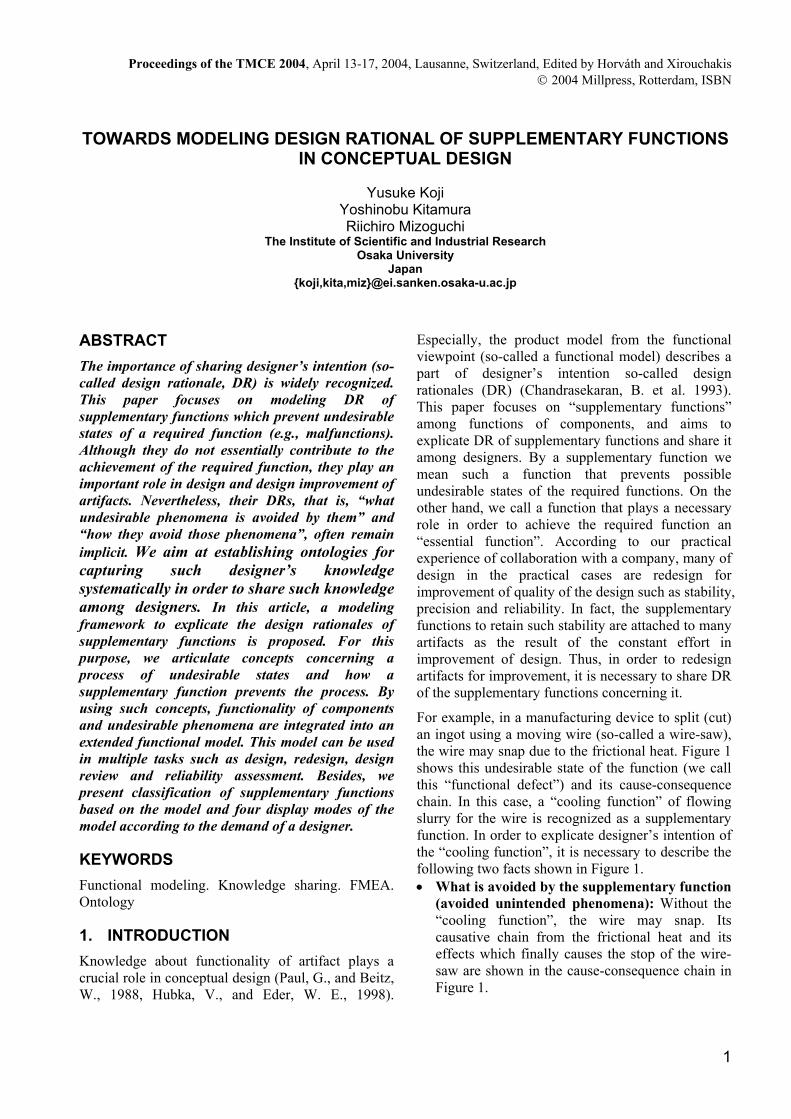
For example, in a manufacturing device to split (cut) an ingot using a moving wire (so-called a wire-saw), the wire may snap due to the frictional heat. Figure 1 shows this undesirable state of the function (we call this “functional defect”) and its cause-consequence chain. In this case, a “cooling function” of flowing slurry for the wire is recognized as a supplementary function. In order to explicate designer’s intention of the “cooling function”, it is necessary to describe the following two facts shown in Figure 1. • What is avoided by the supplementary function
(avoided unintended phenomena): Without the “cooling function”, the wire may snap. Its causative chain from the frictional heat and its effects which finally causes the stop of the wire- saw are shown in the cause-consequence chain in Figure 1.

Yusuke Koji, Yoshinobu Kitamura, Riichiro Mizoguchi 2
• How to prevent the unintended phenomena (preventing method): In order to avoid the stop of the wire-saw, the cooling function removes the most influential factor i.e. the frictional heat.
The former description constitutes phenomena which are not unintended by the designer. The latter description includes the relation between the unintended phenomena and the functional structure. In other words, it is necessary to integrate the representation of the functional defect and its causes and effects with the representation of the functional structure. This relation is an important part of DR.
Nevertheless, such DRs of supplementary functions have been implicit in engineering practice. A lot of research on representation of product functionality (Paul, G., and Beitz, W., 1988, Gero, J. S., 1990, Chandrasekaran, B., et al. 1993, Chittaro, L., et al. 1993, Umeda, Y., et al. 1996, Hubka, V., and Eder, W. E., 1998) mainly concentrates on normal behaviors intended by designers in nature. On the other hand, unintended phenomena can be found in FMEA (Failure Mode and Effect Analysis) sheets, FTA (Fault Tree Analysis) trees and diagnostic models. However, these models tend to be ad hoc and do not include clear relationship with functional structures. We need both an integrated modeling framework for intended and unintended behaviors and ontological commitments (its importance is pointed out also in (Salustri, F. A., 1998)) on model constituents for systematic description.
Aiming at explicit representation of design rationale of the supplementary functions, this paper discusses an integrated modeling framework of functional
structure and unintended phenomena. The integrated model includes the above two factors of the DR, i.e. the avoided unintended phenomena and the preventing method on the functional model. For this purpose, the cause-consequence chains of the unintended phenomena are ontologically analyzed and then some ontological concepts are identified. On the basis of the ontological consideration, we extend our modeling framework for systematic description of functional models (Kitamura, Y., and Mizoguchi, R., 2003a, b) for integrating unintended phenomena. Its extension to unintended behaviors and user actions was explored in (van der Vegte, W. F., et al. 2002). This paper discusses ontological modeling schema for unintended behaviors. Moreover, supplementary functions are classified according to the preventing method. The display modes and relationship among functions are investigated as well. The modeling framework based on ontological engineering helps designers describe more consistent models.
This paper is organized as follows: Firstly, section 2 presents overview our previous modeling framework for functional structures. Next, the two parts of the DR of a supplementary function, that is, avoided unintended phenomena and preventing method, are explained in sections 3 and 4, respectively. Besides, section 4 discussed classification of supplementary functions. Next, section 5 proposes four modes as the display method of the models according to the demand of a designer. Next, section 6 discusses the relationship among functions. Next, section 7 presents the benefits of our framework, and section 8 discusses related work.
to generatefrictional
heat
to generatefrictional
heat
Cause-consequence chain of unintended phenomena
CoolingFunctionCoolingFunction
to increasetemperature
of wire
to increasetemperature
of wireto decrease
wire strengthto decrease
wire strength to snap wireto snap wire
cause cause causecause
to split ingot
to split ingot
not to split ingot
not to split ingot
state change
required state ofsub-function
undesirable state
Influence for stopping the chainto make
frictional forceto make
frictional force
not to make frictional forcenot to make
frictional force
……
required state ofwhole-function(required function)
Causative chain Propagation chain
to generatefrictional
heat
to generatefrictional
heat
Cause-consequence chain of unintended phenomena
CoolingFunctionCoolingFunction
to increasetemperature
of wire
to increasetemperature
of wireto decrease
wire strengthto decrease
wire strength to snap wireto snap wire
cause cause causecause
to split ingot
to split ingot
not to split ingot
not to split ingot
state change
required state ofsub-function
undesirable state
Influence for stopping the chainto make
frictional forceto make
frictional force
not to make frictional forcenot to make
frictional force
……
required state ofwhole-function(required function)
Causative chain Propagation chain
Figure 1 A cause-consequence chain of unintended phenomena avoided by cooling function in the wire-saw

TOWARDS MODELING DESIGN RATIONAL OF SUPPLEMENTARY FUNCTIONS IN CONCEPTUAL DESIGN 3
2. OVERVIEW OF OUR FRAMEWORK OF FUNCTIONAL MODELING
On the basis of ontological engineering in artificial intelligence, a modeling framework for functional models and functional knowledge has been developed (Kitamura, Y., and Mizoguchi, R., 2003a,b). This section gives its overview as a basis of extension.
In the framework, a function of a device is defined as the teleological interpretation of its “behavior” under the intended goal (Sasajima, M., et al. 1995). The “behavior” of a device is defined as the objective (without designer’s intention) interpretation of its input-output relation as a black box based on a device-centered ontology. A device is connected to another device through its input or output ports. A device as an agent changes states of things input (called operands) such as substance like fluid, energy, motion, force and information. The input-output relation of the behavior is, to be exact, the difference between the states of the operand at the input port and that at the output port.
Functions are teleological interpretation of such behaviors under the intended goal. These definitions of behavior and function are similar to those in (Lind, M., 1994, Umeda, Y., et al. 1996) in a sense of intention and to the technical functions in (Hubka, V.,
and Eder, W. E., 1998). However, we explicate mapping primitives between behavior and function (called functional toppings (Sasajima, M., et al. 1995)) and operational conceptualization of the functional concepts. On the other hand, papers such as (Chandrasekaran, B., et al. 1993) define that “behavior” is how to achieve a function. The authors have developed an ontology of generic functions (called the functional concept ontology) with such operational definitions. It defines about 220 concepts in four is-a hierarchies.
Figure 2 indicates an example of a function decomposition tree of the wire-saw. In the function decomposition tree, the whole (macro) function is-achieved-by the sequence of sub (micro) functions (called “is-achieved-by” relations). This relation is a kind of “part-of” relations or aggregation relations among functions. All functions in the function decomposition are instances of the generic functions defined in the functional concept ontology. Such functional structure is similar to the German-style function decomposition in (Paul, G., and Beitz, W., 1986), the whole-part relation in (Lind, M., 1994) and “degree of complexity” in (Hubka, V., and Eder, W. E., 1998). We introduce the way of function achievement as follows.
In order to explicate the knowledge used when the
To makeforce
To makeforce
To exert forceon kerf-loss partTo exert force
on kerf-loss part
To lose biding force of the
kerf-loss part
To lose biding force of the
kerf-loss part
To exertvertical force to ingot and wire
To exertvertical force to ingot and wire
To give linear motion in thewire direction
To give linear motion in thewire direction
To split ingotsTo split ingots
To move the part away
To move the part away
To make frictional force
To make frictional force
To bring ingots into contact with
the wire
To bring ingots into contact with
the wire
To Give wiretension
To Give wiretension
AND
To Give ingotForce in the
wire direction
To Give ingotForce in the
wire direction
Tension wayPrinciple:tension
To transformRotation to
Linear
To transformRotation to
Linear
To give Shaft rotation
motion
To give Shaft rotation
motion
AND
Rotation motion wayPrinciple: Rotation
Roller&BobbinMotor2&Motor3
ToRemove
heat
ToRemove
heatTo
ShutdownTo
ShutdownTo Keep largeFriction coff.
To Keep largeFriction coff.
To Removescrapings
To Removescrapings
To Fix ingotTo Fix ingot
To Set grindingcompound
To Set grindingcompound
To Flow slurryTo Flow slurry
Coolant wayPrinciple:Heat conduction
To Get coolant
to touch
To Get coolant
to touch
Flow wayPrinciple:; Flow
Grinding compoundflow wayPrinciple:Flow
Liquid shock wayPrinciple: Shock
AND
Removing wayPrinciple: kerf-loss
Physical force wayPrinciple: physical force
Liner friction wayPrinciple: friction
AND
AND
Legend
: Supplementary function
: Device
: Essential function
: Way
Roller
Wire Motor
IngotTable
Shaft
AND
To makeforce
To makeforce
To exert forceon kerf-loss partTo exert force
on kerf-loss part
To lose biding force of the
kerf-loss part
To lose biding force of the
kerf-loss part
To exertvertical force to ingot and wire
To exertvertical force to ingot and wire
To give linear motion in thewire direction
To give linear motion in thewire direction
To split ingotsTo split ingots
To move the part away
To move the part away
To make frictional force
To make frictional force
To bring ingots into contact with
the wire
To bring ingots into contact with
the wire
To Give wiretension
To Give wiretension
AND
To Give ingotForce in the
wire direction
To Give ingotForce in the
wire direction
Tension wayPrinciple:tension
To transformRotation to
Linear
To transformRotation to
Linear
To give Shaft rotation
motion
To give Shaft rotation
motion
AND
Rotation motion wayPrinciple: Rotation
Roller&BobbinMotor2&Motor3
ToRemove
heat
ToRemove
heatTo
ShutdownTo
ShutdownTo Keep largeFriction coff.
To Keep largeFriction coff.
To Removescrapings
To Removescrapings
To Fix ingotTo Fix ingot
To Set grindingcompound
To Set grindingcompound
To Flow slurryTo Flow slurry
Coolant wayPrinciple:Heat conduction
To Get coolant
to touch
To Get coolant
to touch
Flow wayPrinciple:; Flow
Grinding compoundflow wayPrinciple:Flow
Liquid shock wayPrinciple: Shock
AND
Removing wayPrinciple: kerf-loss
Physical force wayPrinciple: physical force
Liner friction wayPrinciple: friction
AND
AND
Legend
: Supplementary function
: Device: Device
: Essential function
: Way
Roller
Wire Motor
IngotTable
Shaft
Roller
Wire Motor
IngotTable
Shaft
AND
Figure 2 The function decomposition tree of wire-saw

Yusuke Koji, Yoshinobu Kitamura, Riichiro Mizoguchi 4
designer decomposes a whole function into a sequence of sub functions, the concept of “way of function achievement” have been introduced as conceptualization of background knowledge of functional decomposition such as physical principles and theories. In Figure 2, a way is represented by a small black square that connects the whole function and the sub functions. For example, the way which achieves the “to split ingots” is the “removing way”.
A concrete way in a function decomposition tree is generalized into a generic way (called functional way knowledge). Then, ways to achieve the same function is organized in is-a relations according to their principles. Physical principles as a basis of function achievement is also captured as “means” in (Malqvisit, J., 1997), we discuss generic knowledge (similar to Gero, J. S., 1990; Bhatta, S. R., and Goel, A. K., 1997; Umeda, Y., et al. 1997) and its organization based on ontological principles with a clear relationship with other relations such as is-a relations of functions (Kitamura, Y., and Mizoguchi, R., 2003a,b).
This framework has been successfully deployed in a manufacturing company in Japan since 2001 for sharing engineers’ knowledge about manufacturing devices and manufacturing processes (Kitamura, Y., and Mizoguchi, R. 2003b). Its empirical evaluation by the engineers is very positive. They said that this framework enable them to explicate the implicit knowledge possessed by each designer and to share it among colleagues.
3. MODEL OF AVOIDED UNINTENDED PHENOMENA
3.1. Overview of the model of avoided unintended phenomena
In this section, we extend our framework of functional models in order to describe cause-consequence chain of avoided unintended phenomena related to functional defects. This sub-section shows its overview.
An undesirable state of a function is called a “functional defect”. The ultimate goal of a supplementary function is to prevent a functional defect of a required function (the whole function achieved by the artifact).
The cause-consequence chain starting from the trigger phenomenon to the ultimate functional defect consists of two chains; a cause-consequence chain
which causes an initial functional defect (we call it a causative chain), and a propagation chain of the initial functional defect to the final functional defect of the required function (we call it a propagation chain).
In the example of the wire-saw shown in Figure 1, the cause-consequence chain from “generating frictional heat” to “to snap wire” is a causative chain. On the other hand, if the function “to make frictional force” stops operating due to the disconnection of the wire etc., coarser-grained (the whole) function also stops. Such a propagation of the functional state is a propagation chain.
Figure 3 shows an example of the model of the cause-consequence chain of unintended phenomena avoided by “cooling function” in addition to the function decomposition tree of the wire-saw. The right tree of Figure 3 is a partial function decomposition tree of the wire-saw. The propagation chain can be represented with the function decomposition tree because the defect is propagated through the dependency between functions in most cases (exceptional cases will be mentioned in Section 3.4). On the other hand, the causative chain is described as another tree (the left tree in Figure 3) by using the same description framework as the function decomposition tree. The difference between the two trees is the former is intended but the latter is not intended by designers.
These two chains are interconnected with a link called an “influence relation”. In the example of the wire-saw, the influence relation is the relation between “to split the wire” and “to make frictional force”.
The following sub-sections explain the detail of the model of avoided unintended phenomena. The explanation is given in the order of the propagation chain, the causative chain and the influence relation.
3.2. Propagation chain Functional defect As mentioned above, a propagation chain consists of the functional defects. The functional defect is a kind of functional states, which is an undesirable state depending on the context.
Functional defects can be classified into two categories. One is failing to realize the function (which is called ”malfunction”), and other one is that the attribute of the realized function is undesirable.

TOWARDS MODELING DESIGN RATIONAL OF SUPPLEMENTARY FUNCTIONS IN CONCEPTUAL DESIGN 5
By the “malfunction”, we mean a violation of the intended input-output relation. On the other hand, the attributes of the realized function include efficiency of process, stability of process, precision of products, etc. Functional defects are shown by attaching a balloon to the upper right of each function.
Propagation chain In a propagation chain a functional defect propagates along the function decomposition tree in the bottom up manner. A functional defect causes the next functional defect mainly along the input-output relation of functions. For example, in Figure 3, the malfunction of “to make force” causes the malfunction of “to exert force on the kerf-loss part (i.e., the part lost by cutting)”, since “to exert force on the kerf-loss” cannot be performed without the frictional force. Moreover, generally speaking, if an essential sub-function becomes a functional defect, the whole-function also becomes a functional defect. For example, in Figure 3, the malfunction of “to exert force on the kerf-loss part” causes the malfunction of “to lose binding force of the kerf-loss part”.
Initial functional defect and final functional defect In a series of functional defects which constitute a propagation chain, the functional defect which is located in the most up-stream (that is the deepest
causative functional defect) is called the initial functional defect. And the functional defect which is located in the most down-stream is called the final functional defect.
In the example shown in Figure 3, the initial functional defect is the malfunction of “to make frictional force”. The initial functional defect is represented by the circle balloon. On the other hand, the final functional defect is the malfunction of “to split ingot”. The final functional defect is represented by the star balloon. Other functional defects are represented by the roundbox balloons. In general, the function affected by the last functional defect is the top function of the tree under consideration.
3.3. Causative chain Necessity of causative chain The causative chain is necessary to represent the cause of the initial functional defect, which is called the physical cause in an ontology of faults (Kitamura, Y., and Mizoguchi, R., 1999). In Figure 3, the causative chain represents the reason why “to make frictional heat” causes the malfunction of “to make frictional force”. Since this can not be represented by the propagation of the functional defect, the causative chain is necessary.
To exert forceon kerf-loss part Initial functional defect
Functional decomposition tree
To exertvertical force
to ingotand wire
To give linear motion
in the wiredirection
To make frictional
force
To bring ingot into
contact withwire
To lose bindingforce of the
kerf-loss partTo move
the part away
To split ingot
To make force
malfunction
malfunction malfunction
malfunction malfunction
Final functional defectCausative chain tree
Causative Chain
Causative phenomenon of functional defect
To exertvertical force
to ingot and wire
To givelinear motion
in the wiredirection
To make frictional
heat
To bring ingot into
contact withwire
To decreasestrength
To addforce
To split wire
To transferheat to wire
To make heat
Based on same behavior
malfunction influence
Propagation Chain
To remove heat
Supplementaryfunction
Influence Relation (a)
Trigger phenomenonmalfunction
Figure 3 An example of the integrated model, which is the model of the cause-consequence chain avoided by “to remove heat” integrated with the function decomposition tree of the wire-saw

Yusuke Koji, Yoshinobu Kitamura, Riichiro Mizoguchi 6
General unintended phenomenon Phenomena which constitute a causative chain are called “general unintended phenomena”. In Figure 3, each circle nodes of the left tree (which is labeled as causative chain tree) are the general unintended phenomena.
A general unintended phenomenon is a concept similar to a function. That is, the general unintended phenomenon means a conceptualization of the result of teleological interpretation of its behavior under the pseudo-goal. By pseudo-goal, we mean a state which is unintentionally achieved by the sequence of phenomena initiated by an intended function.
Decomposing general unintended phenomenon Like the function, the general unintended phenomenon can be decomposed into sub-general unintended phenomena, and then generic knowledge of way of function achievement (Kitamura, Y., and Mizoguchi, R., 2003a) can be used. In Figure 3, for example, “to make heat” unintentionally is-achieved-by “to bring the ingot into contact with the wire”, ”to exert vertical force to ingots and the wire”, “to give linear motion in the wire direction” and “to make frictional heat”. Its way of function achievement is “friction way”. The friction way is a generic way like other way in the function decomposition tree. This way probably can be used to achieve the required function of other artifact, such as to increase the temperature.
Causative chain The left tree in Figure 3 (which is called a causative chain tree) represents the causative chain with the decomposition relations among general unintended phenomena discussed thus far. The general unintended phenomena at the top of the causative chain tree (called “causative phenomenon of functional defect”) is the direct cause of the initial functional defect. In Figure 3, “to split wire” is the direct cause of malfunction of “to make functional force”, that is the causative phenomenon of the functional defect.
Trigger of a causative chain A “trigger phenomenon” of a causative chain is the most up-steam one in the causative chain. In Figure 3, it is “to make frictional heat”. Its operand (which is an entity or substance changed by the phenomena) such as the frictional heat in Figure 3 is called a “trigger object”. A trigger is either internal or external. By the internal trigger, we mean the trigger
object is generated by an essential sub-function in the function decomposition tree as a side effect. The trigger phenomenon is a different interpretation of the same behavior of the essential function. In Figure 3, the frictional heat is inevitably but unintentionally caused by an essential sub-function “to make frictional force”. On the other hand, the external trigger represents an influence from the outside of the scope of the model building like the environment or users.
3.4. Exceptional cases No causative chain As an exceptional case, no causative chain may be described as a cause of the initial functional defect. In general, there is the general unintended phenomenon which is the cause of the functional defect. However, in some cases, any supplementary functions can not prevent the general unintended phenomena such as natural phenomenon. In such cases, designers will omit the description of the causative chain. In these cases, from the viewpoint of functional design, since the reason of undesirable state can be regarded as an unsuitable choice of the way of function achievement, it is regarded as the cause. Thus, changing the way of the product is the only way in order to prevent the initial functional defect. Of course, even if the initial functional defect is happened, the functional defect of the required function can be prevented by a supplementary function influencing the propagation chain.
In the case of the wire-saw, the frictional way is used in order to achieve the “to make the force” function. Then, it is necessary to make the wire run repeatedly until to split ingot completely. Thus, from this viewpoint, the functional attribute “process efficiency” can be estimated as low. If this evaluation is regarded as undesirable, the “to make force” becomes a functional defect, and its cause is “the friction way”.
Propagation off the functional structure Basically, the functional defects in the propagation chain propagate along the functional structure as shown in Figure 3. In this case, the propagation chain can be represented using only the function decomposition tree with the balloons. However, in some cases, the functional defects propagate outside of the functional structure. In these cases the propagation off the functional structure can be represented using another tree which consists of

TOWARDS MODELING DESIGN RATIONAL OF SUPPLEMENTARY FUNCTIONS IN CONCEPTUAL DESIGN 7
general unintended phenomena. This additional tree shows unintended paths of influences among functions.
3.5. Unintended phenomenon Both the functional defects discussed in Section 3.2 and the general unintended phenomena in Section 3.3 are unintended by designer. Thus, both concepts are sub-concepts (sub-types) of “unintended phenomena”. In general, phenomena which occur in an artifact are categorized into intended phenomena by designers or unintended phenomena. The intended phenomena correspond to functions of components.
3.6. Influence relation Influence relation In Figure 3, the link between “to split wire” and “to make frictional force” represents an influence relation. This influence relation represents that the “to make frictional force” function is changed to malfunction by breaking the agent of the function, that is the wire, and it causes a malfunction of the required function finally. In general, an influence relation represents the influences of a general unintended phenomenon on a function, and changes it to a functional defect. (As mentioned in Section 4, the influence relation is also used when a supplementary function influences the unintended phenomenon.)
Representation of influence relations The influence relation is shown by an arrow drawn from the influencing phenomenon to the circle blowoff of the influenced phenomenon, which represents the change of the attribute. The alteration factor of the influence relation discussed in the following paragraphs is described on the arrow as the name.
The five factors of an influence relation The influence relation is described in terms of the following five factors. For example, the influence relation in Figure 3 (which is labeled as Influence Relation (a)) is described in Table 1.
Table 1 reads that the general unintended phenomenon “to split the wire” irreversibly causes malfunction of the “to make frictional force” and this influence disrupts the required function.
Alteration The alteration factor represents which attribute of the influenced function (“to make frictional force” in this case) is changed and whether the attribute is increasing or decreasing. This “increase or decrease” means not the change depending on a teleological context but the only physical change of the attribute. Like the influence relation (a), the malfunction is regarded as a kind of the alteration. The other example alterations are decrease of the efficiency, decrease of the stability and so on.
Object The object factor represents what of the function is changed. In general, the object is classified into the input entity and the device. Changing the input entity means changing the input entity which has already been described in the functional model or adding a new entity to input. Moreover, the case of adding a new entity is classified into two cases: (1) a new entity is input directly, (2) a new entity is input by using the other input entity which has existed already as the medium. On the other hand, in the case of influencing the device, the general unintended phenomenon regards a device of the function as the operand. That is, the role of the entity is shifting from a device to an operand.
Contribution Contribution means whether the influence is preventive or disruptive for the required function in the context. The contribution is always “disruptive” in the case discussed thus far, that is, when the influence relation is a relation from a general unintended phenomenon to a function.
Reversibility Reversibility means reversibility of the change by the influence relation. By reversible influence, we mean if the general unintended phenomenon is stopped, the influenced function will return to the normal state.
Table 1 Each factor of Influence relation (a)
Alteration Object Contribution Reversibility Time
Influence
Relation (a) Malfunction Device (wire) disruptive Irreversible
Intermittent
Operating

Yusuke Koji, Yoshinobu Kitamura, Riichiro Mizoguchi 8
By irreversible influence, we mean even if the general unintended phenomenon is stopped, the function will retain the changed state.
Time Time means whether the influence is continuous or intermittent, and whether the function is the operating state or the pause state when the function is influenced.
4. PREVENTING METHOD
4.1. Modeling preventing method by influence relation
The eventual goal of a supplementary function is to prevent a functional defect of the required (whole) function. For this purpose, it influences something locating in the cause-consequence chain to block the propagation of the functional defect. This influence can be represented by the framework of the influence relation, which is discussed in Section 3. Figure 4 shows an example of a model of a preventing method
by the influence relation (labeled with the influence relation (b)). The supplementary function is “to remove heat”, and it prevents the same functional defect shown in Figure 3. The influence relation (b) represents that the “to remove heat” function blocks the general unintended phenomenon; “to transfer heat to wire” and it prevents the resultant unintended phenomena.
This influence relation (b) is described in Table 2 using the same five factors discussed in Section 3.6. Table 2 reads that the supplementary function “to remove heat” causes reversibly blocking a phenomenon of the “to transfer heat to wire” by influencing the input object function, and this influence prevents the change to the functional defect of the required function..
The key difference from the influence relation (a) is that “contribution” is preventive. That is to say, although an influence from a general unintended phenomenon to a function and an influence from a supplementary function to an unintended
To exert forceon kerf-loss part
Functional decomposition tree
To exertvertical force
to ingotand wire
To give linear motion
in the wiredirection
To make frictional
force
To bring ingot into
contact withwire
To lose bindingforce of the
kerf-loss partTo move
the part away
To split ingot
To make force
malfunction
malfunction malfunction
malfunction malfunction
Causative chain tree
To exertvertical force
to ingot and wire
To givelinear motion
in the wiredirection
To make frictional
heat
To bring ingot into
contact withwire
To decreasestrength
To addforce
To split wire
To transferheat to wire
To make heat
malfunction influence
To removeheat
Supplementaryfunction
Influence Relation (a)
malfunction
To bring coolant into
contact with wire
To getcoolant to touch
Stop phenomenon influence
stop
stop stop
stop
Influence Relation (b)
Figure 4 An example of the integrated model, which is the model of the influence method of “to remove heat” integrated with the model in Figure 3
Table 2 Each factor of Influence Relation (b)
Alteration Object Contribution Reversibility Time
Influence
Relation (b)
Block a
phenomenon
Input object
(heat) Preventive Reversible
Continuous
Operating

TOWARDS MODELING DESIGN RATIONAL OF SUPPLEMENTARY FUNCTIONS IN CONCEPTUAL DESIGN 9
phenomenon have the same semantics, the contribution factor is different.
4.2. Classification of supplementary functions
The supplementary functions can be classified into the following five kinds according to where of the cause-consequence chain the supplementary function influences. Figure 5 shows the patterns of the influence point of each type of supplementary functions. • Type A : Type A influences an essential function
in order to prevent the generation of the trigger object of the causative chain before the trigger object is generated. Type B : Type B influences a general unintended phenomenon in the causative chain in order to prevent the initial functional defect.
• Type C1 : Type C1 influences a functional defect in the propagation chain in order to stop the propagation along the functional structure.
• Type C2 : Type C2 influences a phenomenon in the propagation chain off the functional structure.
• Type D : Type D supplementary function activates an alternative function when a functional defect in the propagation chain occurs. The alternative function includes to provide the same functionality and to compensate the results of the functional defect.
This classification of the supplementary function is useful to improve the design, since a supplementary function in a current design can be replaced with a supplementary function of the different types.
5. CONTRIBUTION RELATION AND IS-ACHIEVED-BY RELATION
This section shows more detailed definition of supplementary functions. For this purpose, this section represents two relations; is-achieved-by relation and contribution relation. Figure 6 shows these relations.
Supplementary functions have supplementary achievement relation to the whole function. This relation is not necessary to the whole function, and represents the support of essential achievement relation. In order to support, a supplementary function has a supplementary-contribution to an essential function.
5.1. Contribution relation By a contribution–relation, we mean a relation between sub-functions in the same grain size in a function decomposition tree. The contribution relations are classified into main-contribution and supplementary-contribution. An essential function makes a main-contribution to other essential function or receives a main-contribution from another essential function. On the other hand, a supplementary function makes a supplementary- contribution to an essential function.
In the case of a Type C1 supplementary function, the alteration factor of its influence relation tends to be used for the name of the contribution relation, since a function which is influenced by the supplementary function and a function which receives the supplementary contribution are the same function. However, they are different concepts.
The contribution relation is the same concept as the meta-functions (Kitamura, Y., et al., 2002). Sub concepts of the main- contribution are considered like ToProvide, ToDrive and ToEnable of the meta-functions. Subconcepts of the supplementary-contribution are under investigation.
5.2. Is-achieved-by relation The is-achieved-by relation is the relation between a whole-function and its sub-functions. This relation is classified into essential achievement relation and supplementary achievement relation. A sub-function which makes the essential achievement relation to a
Function Function
Function
Function Function
GUP GUP
GUP
GUP GUP
Function
Function
Supplementaryfunction
Influencerelation
FD FD
FD
FD
TYPE A
TYPE C1
TYPE B
GUP GUP
GUP
Influencerelation
TYPE C2
Causative Chain
Propagation ChainGUP: General Unintended PhenomenaFD : Functional Defect
Function Function
Function
Function Function
GUP GUP
GUP
GUP GUP
Function
Function
Supplementaryfunction
Influencerelation
FD FD
FD
FD
TYPE A
TYPE C1
TYPE B
GUP GUP
GUP
Influencerelation
TYPE C2
Causative Chain
Propagation ChainGUP: General Unintended PhenomenaFD : Functional Defect
Figure 5 The classification of supplementary functions according to where the cause-consequence chain is influenced

Yusuke Koji, Yoshinobu Kitamura, Riichiro Mizoguchi 10
whole-function fulfills one or more of the following three conditions. • making main-contribution to another sub-function • receiving main-contribution from another sub-
function • receiving supplementary-contribution from
another sub-function
On the other hand, a sub-function which makes supplementary-contribution to another sub-function makes supplementary achievement relation to the whole-function.
A set of sub-functions which make essential achievement relation to the whole-function should definitely be described in a way of function achievement. Sub-functions which make supplementary achievement relation to the whole-function should be distinguished from essential functions, in order to keep the generality of knowledge of the way of function achievement, since they are not indispensable in order to achieve the whole function and they exist depending on a context.
6. DISPLAY MODE We have explained the concepts in order to explicate the DR of supplementary functions, such as the functional defect and the influence relation. However, designers do not always want to see all kinds of them at the same time. Rather, it is desirable to display information adaptively to designer’s interest. Four display modes of the model according to the demand of a designer are as follows. • Functional mode
In this mode, the is-achieved-by relations among intended phenomena, which are essential functions and supplementary functions, are shown in the function decomposition tree.
• Avoided unintended phenomena mode
In this mode, in order to explicate the reason for why a specific supplementary function has been designed, the unintended phenomena that possibly occur if the supplementary function is not installed are displayed. That is, the causative chain of the functional defect, its propagation chain, and the influence relation between them are displayed in addition to the functional mode. Figure 3 is an example of this mode.
• Preventing method mode This mode is the mode to explicate how a specific supplementary function prevents the functional defect of the required function. Thus, the influence relation made by the supplementary function and the propagation of the change by the influence are displayed in addition to the avoided unintended phenomena mode. Figure 4 is an example of this mode.
• Summary mode If the avoided unintended phenomena of all supplementary functions in a function decomposition tree are displayed, it is hard to understand since the display becomes complex. Moreover, it is not necessary to display all information simultaneously. This mode is to display the DR of each supplementary function in a summary style. In this mode, the initial functional defect, the final functional defect and the trigger of the causative chain are displayed in addition to the functional mode. The trigger is displayed by attaching a balloon to the phenomenon which generates the trigger, and an arrow is drawn from the supplementary function to the balloon of the essential function receiving supplementary- ontribution.
7. BENEFITS OF OUR FRAMEWORK In order to explicate DR of supplementary functions, our framework helps designers describe both what is prevented by the supplementary functions and how to prevent it systematically. It makes designers notice unclear part in the design and understand their design deeper. Besides, such models are understood easier by other designers.
One of the features for systematic description is that the conceptualization of “way of function achievement” in our framework helps us to keep how to achieve a function” from “what is achieved”. For example, “to weld steel” is not just a function but a function implying a specific way of achievement, i.e., fusing the target operand. Such concepts should be
Sub Function(Essential Function)
Sub Function(Essential Function)
Sub Function(Essential Function)
Sub Function(Essential Function)
Whole FunctionWhole Function
Sub Function(Supplementary Function)
Sub Function(Supplementary Function)
Essentialachievement relation
Essential achievement relation
Supplementary achievement relation
Main Contribution
SupplementaryContribution
Sub Function(Essential Function)
Sub Function(Essential Function)
Sub Function(Essential Function)
Sub Function(Essential Function)
Whole FunctionWhole Function
Sub Function(Supplementary Function)
Sub Function(Supplementary Function)
Essentialachievement relation
Essential achievement relation
Supplementary achievement relation
Main Contribution
SupplementaryContribution
Figure 6 The contribution relations and is-achieved-by relations

TOWARDS MODELING DESIGN RATIONAL OF SUPPLEMENTARY FUNCTIONS IN CONCEPTUAL DESIGN 11
decomposed into “joining” function and “fusion” way. The same benefit can be gained in the case of unintended phenomena. It helps us to keep “how to happen unintended phenomena” from “what is happened”.
Another benefit can be brought by a knowledge base of knowledge of way of function achievement. The designer can explore possible deeper phenomena which cause an unintended phenomenon by consulting the knowledge base.
Our model can be used in various scenes of design such as conceptual design, redesign and reliability assessment. Required information in terms of these tasks, that is, functional structure and unintended phenomena can be included in this model. Some examples are as follows.
In design review In general, there are many possible functional defects in an artifact. One of important goals of a design review is to check whether possible defects have been considered and how to avoid them. Our framework provides a representational schema of the avoided unintended phenomena and the preventing method as a knowledge medium for such discussion. As the result, other designers can understand whether the designer has sufficiently considered possible functional defects.
In the example of the wire-saw, our models can represent that the alternative (multiple) triggers, such as “frictional heat” and “extra tension”, cause a specific initial functional defect, such as malfunction of “to make frictional force”, since they are included in OR relationship. Moreover, “to flow slurry”, which is a sub-function of the supplementary function “to remove heat”, is also achieving other supplementary functions such as “to remove scrapings” (as shown in Figure 2). Removing scrapings prevents the final functional defect “the decrease of precision of split ingots”, and its trigger object is “scrapings”. That is, this model represents that “to flow slurry” have multiple roles.
In redesign When a designer replaces the way of function achievement with another way, it is possible to understand whether the supplementary function is still required or not. In the example of “to flow slurry”, if the “friction way” for making force function is replaced by an alternative way, say “inner-diameter blade way”, it can be understood
whether flowing slurry is required or not. In this case, flowing slurry is still required. Its reason is that the scrapings still cause to decrease the precision, although the frictional heat, which the trigger objects for splitting wire in the friction way, does not cause to break the inner-diameter blade.
In addition, it is easier for the designer to notice another method to prevent a functional defect of required function better. This is because the other unintended phenomena to be possibly blocked by the supplementary function are represented in the model of the avoided unintended phenomena.
For example in Figure 4, one of possible alternative methods to prevent the breakage of the wire is to control tension of the wire according to decreasing the strength of the wire.
8. RELATED WORK Models of functional defect (failure of function or malfunction) are found in reliability assessment. In FMEA (Failure Mode and Effect Analysis), which is a method for reliability assessment, a FMEA sheet includes sets of a failure mode of a component, its possible cause and its effect on other components etc. They correspond to a trigger phenomenon, an initial functional defect and a final functional defect in our framework, respectively. In order to perform FMEA capturing many potential failures, it is necessary to understand the behavior of the product. Thus some models such as block diagrams, which represent mainly connections among components, are used in traditional FMEA. However, since the relationship between FMEA and such models is not clear, many potential failures tended to be overlooked.
In order to capture a larger set of failure modes systematically, there is research on advanced FMEA (e.g. Steven, K. et al., 1999, Hata, T. et al., 2000) using behavioral models to simulate device behaviors. However, the models used in such research can not deal with the causative chain of a functional defect. Thus, DRs of many supplementary functions to block a certain unintended phenomena in a causative chain cannot be represented sufficiency.
In the model of (Hata, T. et al., 2000), some relations such as support and fixation that constrain motions of components can be represented as functional constraint. In our framework, they are described as a functional structure of kinetic functions of components.

Yusuke Koji, Yoshinobu Kitamura, Riichiro Mizoguchi 12
The formalism of FT (Fault Tree) is similar to our model of unintended behaviors. However, fault trees tend to be ad hoc and some phenomena in the middle of a causal chain tend to be omitted. Our models of unintended behaviors can be consistently described and are not partly omitted, since they are based on the way of function achievement. Moreover, although propagation chains of functional defect have a close relation to the functional structure of the product, such relation cannot be represented in FT.
In model-based diagnosis community, product models of normal (intended) behavior also are used (e.g. De Kleer, J., and Williams, B. C., 1987). These models can deduce the propagation chain of a functional defect. However, the causative chains cannot be described, since the causative chain is independent of the normal behaviors.
Moreover, Davis, R. (1984) and Böttcher, C. (1995) pointed out that typical model-based diagnostic system cannot deal with an unusual interaction between components like “leakage”. Our model can deal with such interaction by using the propagation chain off the functional structure and the influence relation.
The diagnosis using hierarchical functional models instead of behavior models are proposed in (Chittaro, L. et al., 1993, Larsson, J. E., 1996). Although the models are similar to our model from the viewpoint of using functional model, they cannot represent the causative chain neither.
In the research area on reliability of artifacts and failure physics, general phenomena appeared in the causative chains has been investigated on (Shiomi, H., 1977). A categorization of generic faulty phenomena such as SCWIFT (abbreviation of Stress, Corrosion etc.) has been identified (Shiomi, H., 1977). In our work, such phenomena are organized as generic ways of function achievement for unintended behaviors. Such generic organization and its integration with ways for intended phenomena are under investigation.
Some kinds of functions similar to supplementary functions are proposed in a literature. Paul, G. and Beitz, W. (1988) distinguish between main and auxiliary functions. The former are defined as those sub-functions that serve the overall function directly. On the other hand, the latter are defined as those sub-functions that serve the overall function indirectly. They point out that the auxiliary functions have supportive or complementary characters. Hubka, V.
and Eder, W. E. (2001) define additional functions that allow (ensure or support) the working functions to fulfill their tasks. They point out that the working functions and the additional function are loosely equivalent to the main functions and the auxiliary (secondary) functions, respectively.
We define the supplementary functions from the viewpoint of not only its essentiality but also influences on unintended phenomena. In the former sense, supplementary functions are similar to the auxiliary functions and the additional functions. The supplementary functions contribute to the whole (macro) functions in the inessential manner by avoiding a functional defect of required function that possibly occurs without such a function.
Limitation Our model does not include explicit representation concerning shape and time. Therefore, our model can not deal with an error of timing for example. Temporal representation was discussed in (van der Vegte, W. F., et al. 2002).
Besides, a modeling cost is high. A designer has to describe many nodes and links to make a model based on our framework. However, once a designer describes a model, the model can be used for multiple different purposes such as redesign and reliability assessment. Thereby, this limitation can be eased at some level.
9. SUMMARY AND FUTURE WORK We have discussed a modeling framework of DR of supplementary functions. The framework based on ontology engineering integrates the unintended phenomena into a functional model. In our model, a cause-consequence chain of avoided unintended phenomena consists of a causative chain and a propagation chain, and those are connected by an influence relation. An influence of a supplementary function to unintended phenomena is also represented as an influence relation.
As a long-term goal, we aim at our framework as an intermediate language among multiple tasks related to production activity, such as design, design review, redesign and reliability assessment. A model dependent on a certain task could be transformed from an intermediate model. Such knowledge transformation is under investigation.
ACKNOWLEDGMENTS

TOWARDS MODELING DESIGN RATIONAL OF SUPPLEMENTARY FUNCTIONS IN CONCEPTUAL DESIGN 13
This research is intended as a part of modeling framework for collaboration research with Mr. Wilfred van der Vegte and Prof. Imre Horváth, Delft University of Technology. The model of a wire-saw as example in this paper is adopted from the deployment in the Production Systems Engineering Division of Sumitomo Electric Industries. The authors would like to thank Tomonobu Takahashi for his contribution.
REFERENCES Bhatta, S. R. and Goel, A. K., (1997), “A Functional
Theory of Design Patterns”, Proceedings of IJCAI-97, pp.294-300.
Böttcher, C., (1995), “No fault in sructure? - how to diagnose hidden interactions”, Proceedings of IJCAI-95, pp.1728-1733.
Chandrasekaran, B., Goel, A. K., and Iwasaki, Y., (1993), “Functional Representation as Design Rationale”, IEEE Computer, Vol. 26(1), pp.48-56.
Chittaro, L., Guida, G., Tasso, C. and Toppano, E., (1993), “Functional and Teleological Knowledge in the Multi-Modeling Approach for Reasoning about Physical Systems: A Case Study in Diagnosis”, IEEE Transactions on Systems, Man, and Cybernetics, Vol. 23(6), pp. 1718-1751.
Davis, R., (1984), “Diagnostic reasoning based on structure and behavior”, Artificial Intelligence, Vol. 24, pp. 347-410.
De Kleer, J., and Williams, B.C., “Diagnosing Multiple Faults”, Artificial Intelligence, Vol. 32, pp. 97-130
Gero, J., S., (1990), “Design Prototypes: A Knowledge Representation Schema for Design”, AI Magazine, Vol. 11(4), pp. 26-36.
Hata, T., Kobayashi, N., Kimura, F., and Suzuki, H., (2000), “Representation of Functional Relations among Parts and Its Application to Product Failure Reasoning”, Proceedings of CIRP International Seminar on Design.
Hubka, V., and Eder, W. E., (1998), “Theory of Technical Systems”, Springer-Verlag, Berling.
Hubka, V., and Eder, W., E., (2001), “Functions Revistied”; Proceedings of International Conference on Engineering Design 01.
Kitamura, Y., and Mizoguchi, R., (1999), “An Ontological Analysis of Fault Process and Category of Faults”, Proceedings of Tenth International Workshop on Principles of Diagnosis (DX-99), pp. 118-128.
Kitamura, Y., Sano, T., Namba, K., and Mizogurhi, R., (2002), “A Functional Concept Ontology and Its Application to Automatic Identification of Functional
Structures”, Advanced Engineering Informatics, Vol. 16(2), pp. 145-163.
Kitamura, Y., and Mizoguchi, R., (2003a), “Ontology-based description of functional design knowledge and its use in a functional way server”, Expert Systems with Application, Vol. 24(2), pp. 153-166.
Kitamura, Y., and Mizoguchi, R., (2003b), “Organizing knowledge about functional decomposition”, Proceedings of 14th International Conference on Engineering Design (ICED-03).
Larsson, J. E., (1996) “Diagnosis based on Explicit Means-ends Models”, Artificial intelligence, Vol. 80, pp. 29-93.
Lind, M., (1994), “Modeling Goals and Functions of Complex Industrial Plants”, Applied artificial intelligence, Vol. 8, pp. 259-283.
Malmqvist, J., (1997), “Improved function-means trees by inclusion of design history information”, Journal of Engineering Design, Vol. 8(2), pp. 107-117.
Pahl, G., and Beitz, W., (1988), “Engineering design - a systematic approach” Springer-Verlag, New York.
Salustri, F. A., (1998), “Ontological Commitments in Knowledge-based Design Software: A Progress Report”, Proceedings of the Third IFIP Working Group 5.2 Workshop on Knowledge Intensive CAD, pp. 31-51.
Sasajima, M., Kitamura, Y., Ikeda, M., and Mizoguchi, R., (1995), “FBRL: A Function and Behavior Representation Language”, Proceedings of the fourteenth International Joint Conference on Artificial Intelligence (IJCAI-95), pp.1830 – 1836.
Shiomi, H., (1977), “Failure Analysis and Diagnosis”, JUSE Press, Tokyo.
Steven, K., Peder, F., and Ishii, K., (1999), “Advanced Failure Modes and Effects Analysis of Complex Processes”, Proceedings of the ASME Design for Manufacturing Conference.
Umeda, Y., Ishii, M., Yoshioka, M., Shimomura, Y., and Tomiyama, T., (1996), “Supporting conceptual design based on the function-behavior-state modeler”, Artificial Intelligence for Engineering Design, Analysis and Manufacturing, Vol. 10, pp. 275-288.
van der Vegte W.F, Kitamura, Y., Mizoguchi, R., and Horvath, I., (2002), “Ontology-Based Modeling of Product Functionality and Use - Part 2: Considering Use and Unintended Behavior”, Proceedings of The Third International Seminar and Workshop Engineering Design in Integrated Product Development (EDIProD 2002), Lagow, Poland, pp. 115-124.