towards indoor localization using visible light ... · pdf filetowards indoor localization...
TRANSCRIPT
Towards Indoor Localization using Visible Light Communication for
Consumer Electronic Devices
Ming Liu, Kejie Qiu, Fengyu Che, Shaohua Li, Babar Hussain, Liang Wu, C. Patrick Yue
The Hong Kong University of Science and Technology
{eelium, kqiuaa, fyche, slias, bhussain, eewuliang, eepatrick}@ust.hk
Abstract—Indoor localization is the fundamental capability forindoor service robots and indoor applications on mobile devices.To realize that, the cost of sensors is of great concern. In order todecode the signal carried out by the LED beacons, we propose tworeliable solutions using common sensors available on consumerelectronic devices. Firstly, we introduce a dedicated analog sensor,which can be directly connected to the microphone input of acomputer or a smart phone. It decodes both the signal patternand signal strength of a beacon. Secondly, we utilize rolling-shutter cameras to decode the signal pattern, providing potentialsolutions to the localization of hand-held devices with cameras.
In contrast to existing widely-applied indoor localization ap-proaches, like vision-based and laser-based methods, our ap-proach reveals its advantages as low-cost, globally consistent andit retains the potential applications using Visible Light Commu-nication(VLC). We also study the characteristics of the proposedsolutions under typical indoor conditions by experiments.
I. INTRODUCTION
A. Motivation
Research on indoor localization and navigation has long
been a popular topic. Typically, inability or inaccuracy to do
so might cause malfunctions that are not desired. Besides, with
the development of hand-held consumer electronics, location-
based applications and services have drawn great attention.
Unlike the localization problem for outdoor environments,
where Global Positioning System(GPS) can play an effective
and efficient role, indoor localization faces a great challenge
due to the weak indoor GPS signal. Inspired by that, we
propose to use modulated visible light (carried out by white
LEDs) to provide globally consistent signal-patterns to aid
indoor localization.
As for the state-of-the-art, most approaches for localizing a
subject are prone to drift and lack of indoor global references.
Previous research in this field mainly tried to use relatively
high-cost extrinsic devices, e.g. RGB cameras and laser range-
finders, to bargain the requirement of high precision. Con-
versely, we emphasize the fact that the environment should be
intelligent enough to aid the subject to localize (like GPS). At
the same time, the cost on both the subject and the environment
side should be minimized.
Our approach is based on the concept of Visible Light
Communication (VLC) [1]. VLC will be potentially widely
This work was supported by the HKUST project IGN13EG03; partiallysponsored by the Research Grant Council of Hong Kong SAR Government,China, under project No. T23-612/12-R and the HKUST-Qualcomm JointInnovation and Research Laboratory.
used, as it is a form of contactless communication with
numerous advantages compared to traditional ways [2].
B. Contributions
• We design a dedicated driver for LED beacons with
VLC capability, which at the same time could also
support indoor illumination. Also, a photodiode-based
signal processing circuit is made so that both the strength
and the pattern of the light signal can be easily parsed.
• In order to maintain the compatibility to common con-
sumer electronic devices, we propose to use standard
microphone to decode the analog signal captured by the
photonic sensor. We show the effectiveness of the setup.
• We noticed that rolling-shutter cameras, installed on most
smart phones today, could generate striped images deter-
mined by the modulation way of the lights. We propose
a novel algorithm to decode the light pattern.
• We model the luminance distribution for a VLC bulb
in 3D space using Gaussian Process. It provides the
likelihood function for typical filter-based Simultaneous
Localization and Mapping (SLAM) problems.
C. Organization
In Section II, we compare different approaches for indoor
localization. The modulated LED we use is illustrated in
Section III. Then in Section IV, we introduce the decoding
way using photodiode sensor, followed by a introduction to the
architecture of rolling shutter and the algorithm for decoding
the striped image. Next, we present the conduction of our
experiments, followed by the dataset gathering and the analysis
of the result. At the end, we conclude our work and make an
outlook for the work that could be done in the future.
II. RELATED WORK
A. Robotic Localization
Robotic localization mainly deals with three sets of prob-
lems: position tracking [3], topological localization [4], and
global localization [5], of which the latter turns out to be
more challenging since compared to the former, it is not given
the initial position. Most approaches to robotic localization
problems are based on extroceptive sensors, such as laser
range finders , cameras and RGB-D sensors. Liu et al. [6]
developed an algorithm for mobile robot localization with
the representation of image fingerprints from omni-directional
2014 IEEE/RSJ International Conference onIntelligent Robots and Systems (IROS 2014)September 14-18, 2014, Chicago, IL, USA
978-1-4799-6934-0/14/$31.00 ©2014 IEEE 143
cameras. Wang et al. [7] used an image retrieval system of
barcode features to achieve stable localization results. Efficient
visual localization methods using omnidirectional cameras
were introduced in our previous works [8], [9], [10]. These
methods are all based on local features. They suffer from
the shortcoming that almost all similar methods are prone to
drift and lose global accuracy with time. In order to eliminate
the drift and obtain high accuracy, we seemingly must either
use more sophisticated sensors [11] with higher cost or adopt
algorithms with high complexity to attempt to maintain lowest
global cost [12].
B. Low-Cost Localization Approaches
Among low-cost indoor localization solutions, a typical
method is based on Radio Signal Identification(RFID). It could
be implemented in various ways, mainly including using phase
difference [13] and RSSI [14]. But a key disadvantage of
RFID is that indoor environments usually cause radio fre-
quency signal harshly impaired and interfered, thus resulting in
dissatisfaction in performance considering accuracy. Besides,
RFID is usually not compatible with the common setups of
both mobile robots and consumer electronic devices.
C. Visible Light Communication
VLC makes use of visible light as the transmission medium.
A key advantage of VLC is that it could meet both require-
ments of illumination and communication. XW Ng et al.
proposed a medical healthcare information system based on
VLC, mainly considering the disturbance of electromagnetic
waves to medical instruments [15].
Localization-related applications using VLC have also been
reported [16], and VLC based positioning systems have been
discussed in the literature. However, most of these systems
require several types of sensors to work together [17]. A high-
accuracy positioning system based on VLC was proposed by
M. Yoshino et al. [18]. Although the system could measure
both the position and direction of a receiver, it requires
additional image processing procedure which would add to
time consumption. Kim et al. overcome this disadvantage
by using an intensity modulation/direct detection and radio
frequency carrier allocation method [19], but the transmission
channel consumption is relatively high in this case. Moreover,
all these methods require geometrical computation rather than
sensor data modeling. None of the existing works have studied
the sensor model of the VLC for localization application while
we study the distribution model with Gaussian Process.
III. MODULATED LED
To help understand the characteristics especially the modu-
lation bandwidth of commercial LEDs, we first introduce an
optical wireless communication system with discrete compo-
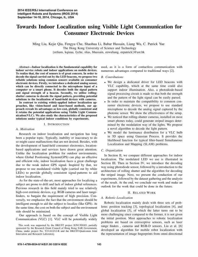
nents, as shown in Fig.1
At the transmitting side, a bulb that consists of 16 LEDs, the
unique ID of each being stored in the non-volatile memory and
used to generate the modulation signal by the micro-controller,
is driven by On-off Keying (OOK) modulator, according to
Fig. 1. Transmitter of the optical wireless communication system
the data pattern of the ID. The optical coupler is employed
to isolate and protect the low-voltage domain supplying the
modulator from the high-voltage part for the power driver.
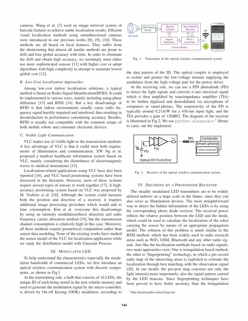
At the receiving side, we can use a PIN photodiode (PD)
to detect the light signals and converts it into electrical signal
which is then amplified by transimpedance amplifier (TIA)
to be further digitized and demodulated via microphone of
computers or smart-phones. The responsivity of the PD is
typically around 0.21A/W for a 436-nm input light, and the
TIA provides a gain of 120dBΩ. The diagram of the receiver
is illustrated in Fig.2. We use python-alsaaudio 1 library
to carry out the implement.
Fig. 2. Receiver of the optical wireless communication system
IV. DECODING BY A PHOTODIODE RECEIVER
The steadily modulated LED transmitters are to be widely
utilized indoors on a large scale in the future, since they can
also serve as illumination devices. The most straightforward
way to detect the hidden information of the LEDs is by using
the corresponding photo diode receiver. The received power
reflects the relative position between the LED and the diode,
which could be used to calculate the localization of the robot
carrying the sensor by means of an appropriate propagation
model. The solution of this problem is much similar to the
RSSI method, which has been widely used in radio research
areas such as WiFi, GSM, Bluetooth and any other radio sig-
nals. Just like the localization methods based on radio signals,
two main approaches exist. One is triangulation based method,
the other is “fingerprinting” technology, in which a pre-record
radio map of the interesting areas is exploited to estimate the
localization through best matching with the observation signal
[20]. In our model, the pre-post map concerns not only the
light intensity,more importantly, also the signal pattern carried
by the LED beacons. Since fingerprinting techniques have
been proved to have better accuracy than the triangulation
1http://pyalsaaudio.sourceforge.net
144
method [21], we take advantage of this factor to enhance the
performance of the localization system.
1) Hardware: Regarding the hardware on the receiving
side, the PD detector only transforms the insight light to
an analog electronic signal despite it costs little. For this
purpose, a low-cost low-frequency PD detector is inadequate.
One suitable analog-to-digital converter is needed. To realize
this function, actually, a common ADC for microphone is
sufficient, which is popular among almost all customer elec-
tronic devices, such as a phone or a laptop. Compared with
other approaches, where extra circuit or interface is required
to decode the signal, the proposed method envisages more
flexibility and possibilities, with relatively lower cost.
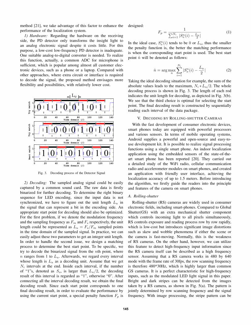
Fig. 3. Decoding process of the Detector Signal
2) Decoding: The sampled analog signal could be easily
captured by a common sound card. The raw data is firstly
binarized for further decoding. To determine the right binary
sequence for LED encoding, since the input data is not
synchronized, we have to figure out the unit length Lu in
the signal that can represent a bit in the encoding side. An
appropriate start point for decoding should also be optimized.
For the first problem, if we denote the modulation frequency
and the sampling frequency as Fm and Fs respectively, the unit
length could be represented as Lu = Fs/Fm sampled points
in the time domain of the sampled signal. In practice, we can
easily adjust these two parameters to get an integer unit length.
In order to handle the second issue, we design a matching
process to determine the best start point. To be specific, we
try to decode the binarized signal from the nth point, where
n ranges from 1 to Lu. Afterwards, we regard every interval
whose length is Lu as a decoding unit. Assume that we get
Ni intervals at the end. Inside each interval, if the number
of “1”s, denoted as So, is larger than Lu/2, the decoding
result of this interval is regarded as “1”, otherwise “0”. After
connecting all the interval decoding result, we obtain the final
decoding result. Since each start point corresponds to one
final decoding result, in order to evaluate the performance by
using the current start point, a special penalty function Fp is
designed:
Fp =1
∑Ni
i=1|Sn
o (i)−Lu
2|
(1)
In the ideal case, Sno (i) tends to be 0 or Lu, thus the smaller
the penalty function is, the better the matching performance
is when the corresponding start point is used. The best start
point n̂ will be denoted as follows:
n̂ = argmaxn
Ni∑
i=1
|Sno (i)−
Lu
2| (2)
Taking the ideal decoding situation for example, the sum of the
absolute values leads to the maximum, Ni ∗Lu/2. The whole
decoding process is shown in Fig. 3. The length of each rod
indicates the unit length for decoding, as depicted in Fig. 3(b).
We see that the third choice is optimal for selecting the start
point. The final decoding result is constructed by sequentially
reading each interval of the data package.
V. DECODING BY ROLLING-SHUTTER CAMERAS
With the fast development of consumer electronic devices,
smart phones today are equipped with powerful processors
and various sensors. In terms of mobile operating systems,
Android supplies a powerful and open-source and easy-to-
use development kit. It is possible to realize signal processing
functions using a single smart phone. An indoor localization
application using the embedded sensors of the state-of-the-
art smart phone has been reported [20]. They carried out
a detailed study of the WiFi radio, cellular communication
radio and accelerometer modules on smart phones, and created
an application with friendly user interface, achieving the
localization accuracy of up to 1.5 meters. Before introducing
the algorithm, we firstly guide the readers into the principle
and features of the camera on smart phones.
A. Rolling-shutter
Rolling-shutter (RS) cameras are widely used in consumer
electronic fields, including smart-phones. Compared to Global
Shutter(GS) with an extra mechanical shutter component
which controls incoming light to all pixels simultaneously,
RS controls exposure and reading process row by row rapidly,
which is low-cost but introduces significant image distortions
such as skew and wobble phenomena if either the scene or
the camera is fast-moving. Normally, this is the weakness
of RS cameras. On the other hand, however, we can utilize
this feature to detect high-frequency input information since
the RS camera itself can be described as a high frequency
sensor. Assuming that a RS camera works in 480 by 640
mode with the frame rate of 30fps, the row scanning frequency
is therefore 480*30Hz, which is highly larger than common
GS cameras. It is a perfect characteristic for high-frequency
inputs, such as the modulated LED light signal in this paper.
Bright and dark stripes can be detected from the images
taken by a RS camera, as shown in Fig. 5(a). The pattern is
jointly determined by row scanning frequency and the signal
frequency. With image processing, the stripe pattern can be
145
decoded. The decoding result reflects the specific modulation
pattern of the LED light signal. Given known LED beacons
associated with locations, this information is an intuitive way
to localize an indoor subject.
For the Complementary Metal-Oxide-Semiconductor
(CMOS) sensor on a smart phone camera, the pixels are
arranged in sequentially activated rows or columns, such that
the image sensor does not capture the entire image at one
shot. RS image sensors are equipped with a readout circuit
which is only able to store the pixels in a single row, thus
the readout timing for different rows cannot overlap. As
discussed, the on and off status of an LED over time can
be encoded in an image, as illustrated in Fig.4. The width
of each stripe depends on how long the unit status lasts
and how fast the rolling shutter works. Specifically, the unit
stripe length is determined by the proportional relationship
between the modulation rate of the LED, which can be
customized and the row scanning rate of the rolling shutter.
Once the unit stripe width is calculated and further calibrated
by experiment, a decoding process is applied to obtain the
corresponding binarized sequence, as well as the original
pattern of an LED beacon. A typical image of a white surface
taken from a rolling shutter camera is shown in Fig. 5.
Fig. 4. Rolling-shutter Operation
(a) Raw Image (b) Ideal Decoding
Fig. 5. Raw Image and the Ideal Decoding Result
B. Algorithm for decoding the striped image
As the striped images are readily feasible, the next issue
is to decode the modulated information. As we can see, the
decoding task seems to be a naive binarization process, but the
practical situation is quite complicated because of the uneven
illumination and various scenes simultaneously captured by
the camera. To handle this problem, an effective algorithm is
proposed in Table 1.
Algorithm to decode the modulated LEDsignal using rolling-shutter cameras
1. Camera configuration2. Image capture3. Pre-processing:
a. Gaussian-blur the imageb. Enhance the contrast by histogram normalizationc. Extract an intermediate curve for the “Decoding” (step 6)
4. Locating the maximal and minimal intensities of the curve5. Obtaining a threshold line and binarization6. Decoding:
a. Calculate the optimal stripe widthb. Determine the optimal start pointc. Decoding by sequential reading and generate decoded bits
7. Reconstructing a binarized image as the final result
TABLE IALGORITHM TO DECODE THE MODULATED LED SIGNAL USING
ROLLING-SHUTTER CAMERAS
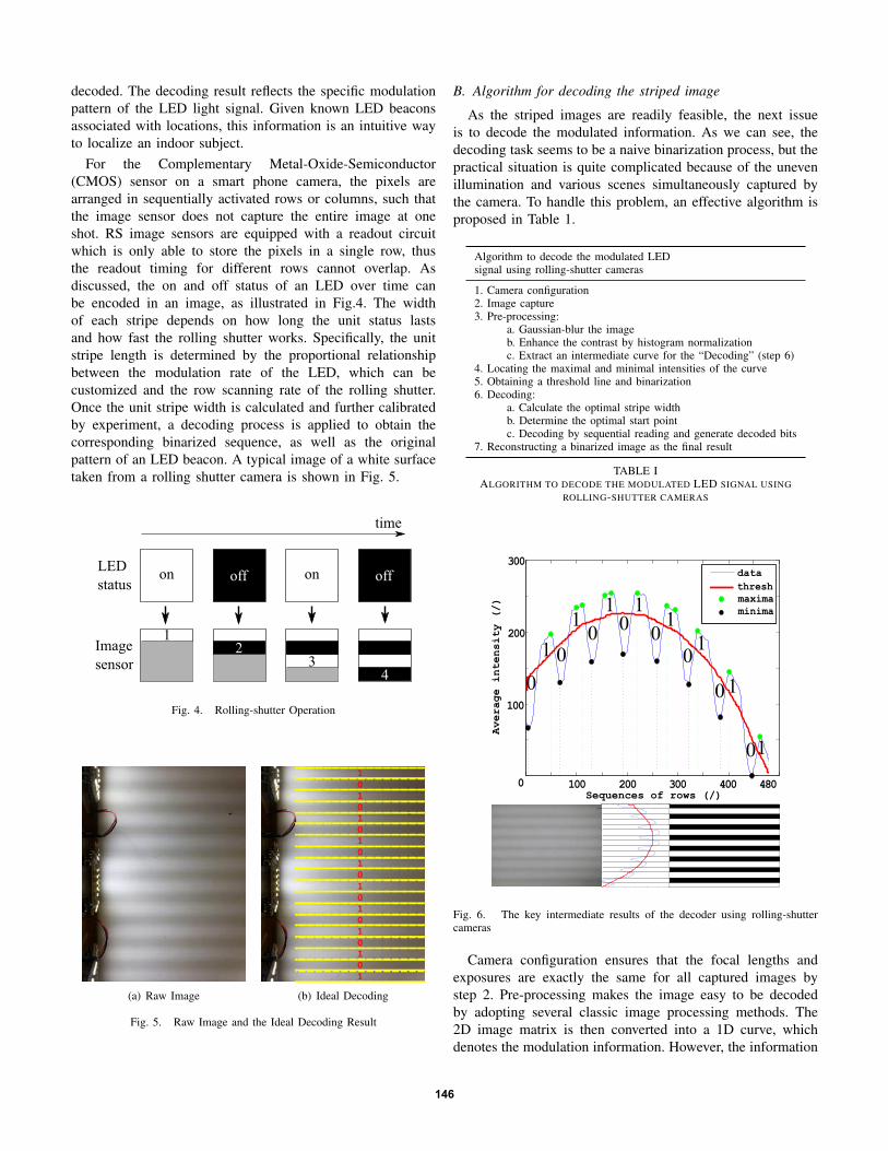
Fig. 6. The key intermediate results of the decoder using rolling-shuttercameras
Camera configuration ensures that the focal lengths and
exposures are exactly the same for all captured images by
step 2. Pre-processing makes the image easy to be decoded
by adopting several classic image processing methods. The
2D image matrix is then converted into a 1D curve, which
denotes the modulation information. However, the information
146

can not be naively extracted by taking the global maxima
and minima, due to unequalized luminance, as shown in Fig.
6. Local maxima and minima denote the center locations of
bright stripes and dark stripes respectively. By connecting all
the maxima and minima in sequence, we get two bounding
curves, namely the maxima curve Lmax and the minima curve
Lmin. Deriving from these two curves, we define a thresh
curve for binarization judgement as follows:
Lthr = αLmax + (1− α)Lmin (3)
where α is the trade-off parameter balancing the weight
between these two curves since the averaging result of the
two curves cannot well satisfy the decoding task. 2 After
binarization, two important issues persist in the decoding
process, which is similar to the decoding process in Section
IV. The first one is calculating the unit stripe width in terms of
pixels that could denote one single modulated bit. The other
is to determine the appropriate start point for decoding. Both
of the problems are quite similar with the resolved ones in
the PD decoder. Thus an identity penalty function is adopted
here. Finally, we reconstruct the binarized image and obtain
the decoding sequence, the whole process is shown in Fig.6.
VI. MODELING OF THE PHOTONIC SENSOR LIKELIHOOD
In order to facilitate potential SLAM applications, a sensor
model is required surrounding the light source, as the system
likelihood. Usually, a posterior is then achieved by multipli-
cation of the likelihood and a position prior. Therefore, the
likelihood is essential for SLAM problems. We adopt a motion
capture system to track both the pose of the LED bulb and the
pose of the sensor with sub-millimeter precision. After that,
a Gaussian Process is implemented for regression using the
following parameter setup. (The readers are referred to the
GPML toolbox 3 document for detailed explanation.) The raw
data for the poses and signal strength, as well as the regression
procedure are animated in the attached video.
• Covariance function: Squared exponential function
• Likelihood function: Multi-variant Gaussian
• Expected mean function: Mean of the input data
• Inference function: Exact inference
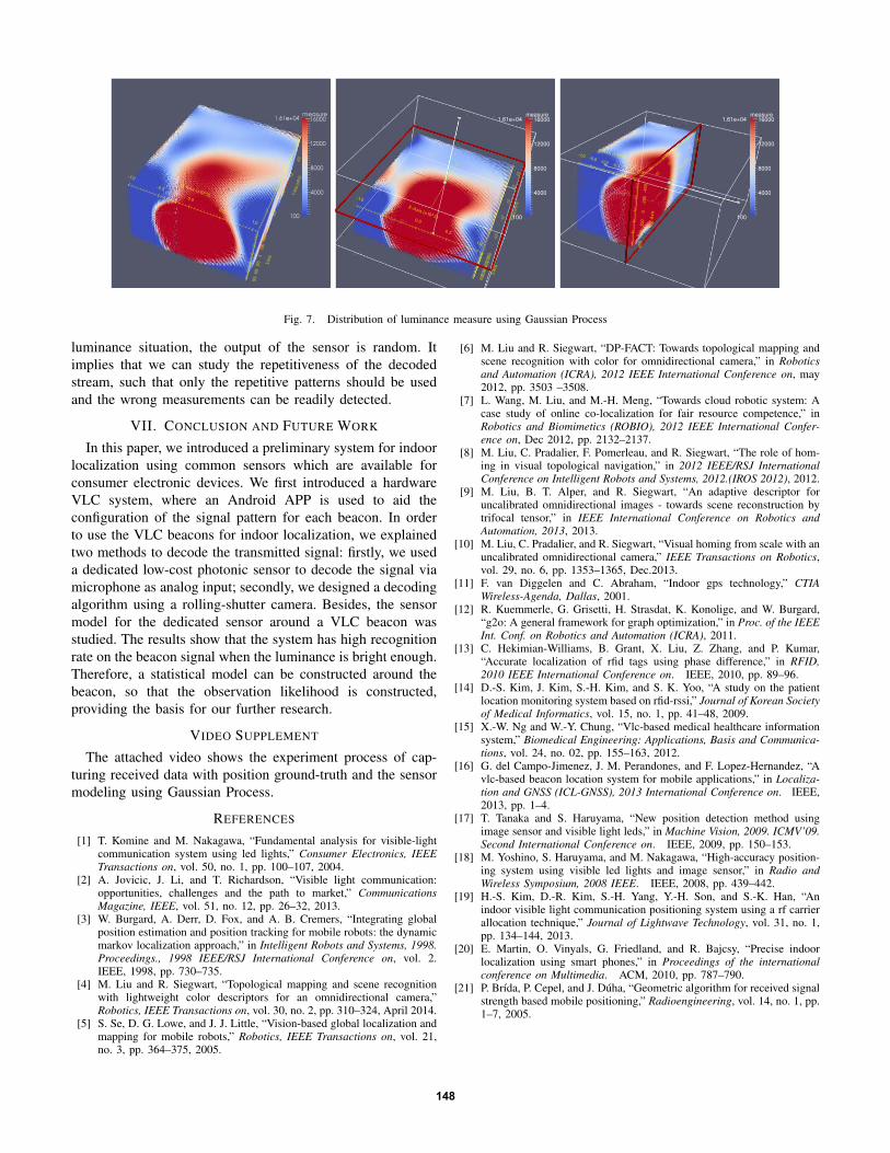
Using the captured 1389 observation pairs distributed
among the 3D space in front of the light source from the
motion capture system and synchronized luminance analog
readings, an interpolated 2.5m x 2.7m x 1.6m 3D model is
shown in Fig. 7. In order to better visualize the 3D space,
two typical section views (horizontal and vertical) are also
depicted. The light source is located at (0,0,0) position. It
can be seen that high luminance measurements are located
right in front of the light source and degraded quickly at a
farther distance. This feature guarantees the valid observation
is within a confined neighborhood of each light source. It
helps improve the localization accuracy, while eliminating the
interference among light sources.
2α is chosen as 0.7 empirically, considering the spreading tendency of the
bright stripes.3http://www.gaussianprocess.org/gpml/
500 1000 1500 2000 2500 30000
0.5
1
1.5
2
2.5x 10
4
Distance to the light source (mm)
Luminance analog measure (/)
lumin vs. distsFitted Luminance vs Distance
500 1000 1500 2000 2500 3000−1.5
−1
−0.5
0
0.5
1
1.5x 10
4
Distance to the light source (mm)
Luminance analog measure (/)
Fitted Luminance vs Distance − residualsZero Line
Fig. 8. Analog luminance Measurements vs Distance to the LED
The plot of luminance measurements against the distance
to the light source is depicted in Fig. 8. It shows that the
luminance is decreasing exponentially along the distance. An
important observation is that the variance at a shorter distance
is usually greater. It indicates that the orientation of the sensor
is essential for the luminance measurement. When the sensor
is far away from the light source, the influence of the sensor
orientation is minor. A more detailed analysis of the effect of
orientation will be shown in our further report.
0 0.5 1 1.5 2 2.5
x 104
0
0.1
0.2
0.3
0.4
0.5
0.6
0.7
BitError Rate
Luminance analog measure (/)
Fig. 9. Errorbit Rate vs Luminance Measurements
Another important factor to evaluate is the error rate respect-
ing with the luminance measure. The result is shown in figure
9. We divide each signal package into 32-bit sub-packages.
The bit error rate is calculated by counting the number of
falsely detected bits over 32. It shows that the bit error rate
can be as high as 60% when the luminance is low. When the
luminance is higher than a threshold, the bit error drops to
zero. A further study to the raw data shows that in the low
147
4000
8000
12000
16000measure
100
1.61e+04
4000
8000
12000
16000measure
100
1.61e+04
Fig. 7. Distribution of luminance measure using Gaussian Process
luminance situation, the output of the sensor is random. It
implies that we can study the repetitiveness of the decoded
stream, such that only the repetitive patterns should be used
and the wrong measurements can be readily detected.
VII. CONCLUSION AND FUTURE WORK
In this paper, we introduced a preliminary system for indoor
localization using common sensors which are available for
consumer electronic devices. We first introduced a hardware
VLC system, where an Android APP is used to aid the
configuration of the signal pattern for each beacon. In order
to use the VLC beacons for indoor localization, we explained
two methods to decode the transmitted signal: firstly, we used
a dedicated low-cost photonic sensor to decode the signal via
microphone as analog input; secondly, we designed a decoding
algorithm using a rolling-shutter camera. Besides, the sensor
model for the dedicated sensor around a VLC beacon was
studied. The results show that the system has high recognition
rate on the beacon signal when the luminance is bright enough.
Therefore, a statistical model can be constructed around the
beacon, so that the observation likelihood is constructed,
providing the basis for our further research.
VIDEO SUPPLEMENT
The attached video shows the experiment process of cap-
turing received data with position ground-truth and the sensor
modeling using Gaussian Process.
REFERENCES
[1] T. Komine and M. Nakagawa, “Fundamental analysis for visible-lightcommunication system using led lights,” Consumer Electronics, IEEE
Transactions on, vol. 50, no. 1, pp. 100–107, 2004.[2] A. Jovicic, J. Li, and T. Richardson, “Visible light communication:
opportunities, challenges and the path to market,” Communications
Magazine, IEEE, vol. 51, no. 12, pp. 26–32, 2013.[3] W. Burgard, A. Derr, D. Fox, and A. B. Cremers, “Integrating global
position estimation and position tracking for mobile robots: the dynamicmarkov localization approach,” in Intelligent Robots and Systems, 1998.
Proceedings., 1998 IEEE/RSJ International Conference on, vol. 2.IEEE, 1998, pp. 730–735.
[4] M. Liu and R. Siegwart, “Topological mapping and scene recognitionwith lightweight color descriptors for an omnidirectional camera,”Robotics, IEEE Transactions on, vol. 30, no. 2, pp. 310–324, April 2014.
[5] S. Se, D. G. Lowe, and J. J. Little, “Vision-based global localization andmapping for mobile robots,” Robotics, IEEE Transactions on, vol. 21,no. 3, pp. 364–375, 2005.
[6] M. Liu and R. Siegwart, “DP-FACT: Towards topological mapping andscene recognition with color for omnidirectional camera,” in Robotics
and Automation (ICRA), 2012 IEEE International Conference on, may2012, pp. 3503 –3508.
[7] L. Wang, M. Liu, and M.-H. Meng, “Towards cloud robotic system: Acase study of online co-localization for fair resource competence,” inRobotics and Biomimetics (ROBIO), 2012 IEEE International Confer-
ence on, Dec 2012, pp. 2132–2137.[8] M. Liu, C. Pradalier, F. Pomerleau, and R. Siegwart, “The role of hom-
ing in visual topological navigation,” in 2012 IEEE/RSJ International
Conference on Intelligent Robots and Systems, 2012.(IROS 2012), 2012.[9] M. Liu, B. T. Alper, and R. Siegwart, “An adaptive descriptor for
uncalibrated omnidirectional images - towards scene reconstruction bytrifocal tensor,” in IEEE International Conference on Robotics and
Automation, 2013, 2013.[10] M. Liu, C. Pradalier, and R. Siegwart, “Visual homing from scale with an
uncalibrated omnidirectional camera,” IEEE Transactions on Robotics,vol. 29, no. 6, pp. 1353–1365, Dec.2013.
[11] F. van Diggelen and C. Abraham, “Indoor gps technology,” CTIA
Wireless-Agenda, Dallas, 2001.[12] R. Kuemmerle, G. Grisetti, H. Strasdat, K. Konolige, and W. Burgard,
“g2o: A general framework for graph optimization,” in Proc. of the IEEE
Int. Conf. on Robotics and Automation (ICRA), 2011.[13] C. Hekimian-Williams, B. Grant, X. Liu, Z. Zhang, and P. Kumar,
“Accurate localization of rfid tags using phase difference,” in RFID,
2010 IEEE International Conference on. IEEE, 2010, pp. 89–96.[14] D.-S. Kim, J. Kim, S.-H. Kim, and S. K. Yoo, “A study on the patient
location monitoring system based on rfid-rssi,” Journal of Korean Society
of Medical Informatics, vol. 15, no. 1, pp. 41–48, 2009.[15] X.-W. Ng and W.-Y. Chung, “Vlc-based medical healthcare information
system,” Biomedical Engineering: Applications, Basis and Communica-
tions, vol. 24, no. 02, pp. 155–163, 2012.[16] G. del Campo-Jimenez, J. M. Perandones, and F. Lopez-Hernandez, “A
vlc-based beacon location system for mobile applications,” in Localiza-
tion and GNSS (ICL-GNSS), 2013 International Conference on. IEEE,2013, pp. 1–4.
[17] T. Tanaka and S. Haruyama, “New position detection method usingimage sensor and visible light leds,” in Machine Vision, 2009. ICMV’09.
Second International Conference on. IEEE, 2009, pp. 150–153.[18] M. Yoshino, S. Haruyama, and M. Nakagawa, “High-accuracy position-
ing system using visible led lights and image sensor,” in Radio and
Wireless Symposium, 2008 IEEE. IEEE, 2008, pp. 439–442.[19] H.-S. Kim, D.-R. Kim, S.-H. Yang, Y.-H. Son, and S.-K. Han, “An
indoor visible light communication positioning system using a rf carrierallocation technique,” Journal of Lightwave Technology, vol. 31, no. 1,pp. 134–144, 2013.
[20] E. Martin, O. Vinyals, G. Friedland, and R. Bajcsy, “Precise indoorlocalization using smart phones,” in Proceedings of the international
conference on Multimedia. ACM, 2010, pp. 787–790.[21] P. Brída, P. Cepel, and J. Dúha, “Geometric algorithm for received signal
strength based mobile positioning,” Radioengineering, vol. 14, no. 1, pp.1–7, 2005.
148