toward large-area sub-arcs econd x-ray...
TRANSCRIPT

Toward large-area sub-arcsecond x-ray telescopes
Stephen L. O’Dell a *, Thomas L. Aldcroft b, Ryan Allured b, Carolyn Atkins c, David N. Burrows d, Jian Cao e, Brandon D. Chalifoux f, Kai-Wing Chan g, Vincenzo Cotroneo b, Ronald F. Elsner a, Michael E. Graham e, Mikhail V. Gubarev a, Ralf K. Heilmann f, Raegan L. Johnson-Wilke d,
Kiranmayee Kilaru h, Jeffery J. Kolodziejczak a, Charles F. Lillie i, Stuart McMuldroch b, Brian D. Ramsey a, Paul B. Reid b, Raul E. Riveros j, Jacqueline M. Roche a, Timo T. Saha k,
Mark L. Schattenburg f, Daniel A. Schwartz b, Susan E. Trolier-McKinstry d, Melville P. Ulmer e, Semyon Vaynman e, Alexey Vikhlinin b, Xiaoli Wang e, Martin C. Weisskopf a,
Rudeger H. T. Wilke d, and William W. Zhang k
a NASA Marshall Space Flight Center, Huntsville, AL 35812, USA b Harvard–Smithsonian Center for Astrophysics, Cambridge, MA 02138, USA
c University of Alabama in Huntsville, Huntsville, AL 35899, USA d Pennsylvania State University, University Park, PA 16802, USA
e Northwestern University, Evanston, IL 60208, USA f Massachusetts Institute of Technology, Cambridge, MA 02139, USA
g University of Maryland Baltimore County, Goddard Space Flight Center, Greenbelt, MD 20771, USA
h Universities Space Research Association, Marshall Space Flight Center, Huntsville, AL 35812, USA
i Lillie Consulting, in collaboration with Northrop-Grumman AOA-Xinetics (USA) j Oak Ridge Associated Universities, Goddard Space Flight Center, Greenbelt, MD 20771, USA
k NASA Goddard Space Flight Center, Greenbelt, MD 20771, USA
ABSTRACT
The future of x-ray astronomy depends upon development of x-ray telescopes with larger aperture areas (≈ 3 m2) and fine angular resolution (≈ 1″). Combined with the special requirements of nested grazing-incidence optics, the mass and envelope constraints of space-borne telescopes render such advances technologically and programmatically challenging. Achieving this goal will require precision fabrication, alignment, mounting, and assembly of large areas (≈ 600 m2) of lightweight (≈ 1 kg/m2 areal density) high-quality mirrors at an acceptable cost (≈ 1 M$/m2 of mirror surface area). This paper reviews relevant technological and programmatic issues, as well as possible approaches for addressing these issues—including active (in-space adjustable) alignment and figure correction.
Keywords: X-ray telescopes, x-ray optics, slumped-glass mirrors, silicon mirrors, differential deposition, ion implantation, active optics, electro-active devices, magneto-active devices
* Contact author (SLO): [email protected]; voice +1 (256) 961-7776; fax +1 (256) 961-7522 Postal address: NASA/MSFC/ZP12; 320 Sparkman Drive NW; Huntsville, AL 35805-1912 USA
Adaptive X-Ray Optics III, edited by Stephen L. O'Dell, Ali M. Khounsary, Proc. of SPIE Vol. 9208, 920805© 2014 SPIE · CCC code: 0277-786X/14/$18 · doi: 10.1117/12.2061882
Proc. of SPIE Vol. 9208 920805-1
Downloaded From: http://proceedings.spiedigitallibrary.org/ on 10/01/2014 Terms of Use: http://spiedl.org/terms
The Chandrprecision Hiunique astrospectrometriastronomy. Tin order to pr
Figure 1ChandraSpacecraInstrume
A consensustelescope wi(< 1″). For identifies the
Here we upreview consiphilosophiesgrazing-incidstatic (§4.2) (§5).
The key perimproves imunresolved s
Larger apertimprovemenineffective istudy of fain
ra X-ray Obseigh-Resolutionophysics faciliic x-ray imageThe US x-ray-ropose as a wo
.NASA’s Chanda flight system aft Module (surents Module (con
s is emergingith aperture areexample, the
ese performanc
date our previiderations relevs for mountingdence mirrors or active (§4.3
rformance memaging quality (sources, by redu
ture area increant in signal-to-nf adjacent sou
nter sources req
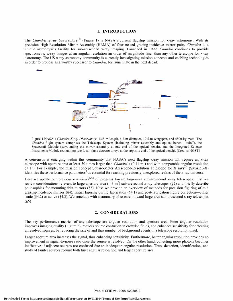
ervatory1,2 (Fign Mirror Assemity for sub-arces at an angulaastronomy com
orthy successor
dra X-ray Obsercomprises the
rrounding the mntaining two foca
g within this cea at least 30 tmission conce
ce parameters5
ious overviewvant to large-a
g thin mirrors (§4): Initial fi
3). We conclud
etrics of any t(Figure 2), reducing the size
ases the signal,noise ratio onc
urces are confuquire both finer
1. INT
gure 1) is NAmbly (HRMAcsecond x-rayar resolution ammunity is curr to Chandra, f
rvatory: 13.8-m Telescope Syst
mirror assemblyal-plane detector
community thatimes larger thept Square-Meas essential fo
ws6,7,8 of progreaperture-area (≈(§3). Next weguring during
de with a summ
2. CON
telescope are duces source coof and thus nu
, thus enhancince the source iused due to inar angular resolu
TRODUCTIO
ASA’s current A) of four nesty imaging. Laan order of mrrently investigfor launch late
length, 4.2-m dem (including m
y at one end ofr arrays at the op
at NASA’s nean Chandra’s
eter Arcsecondor reaching prev
ess toward lar≈ 3 m2) sub-are provide an ov
fabrication (§4mary of research
NSIDERATIO
angular resoluonfusion in cromber of backg
ng sensitivity. s resolved. Onadequate anguution and large
ON
flagship missted grazing-inc
aunched in 19agnitude finergating missionin the next dec
diameter, 19.5-mmirror assemblyf the optical bepposite end of th
ext flagship x(0.11 m2) and
d-Resolution Tviously unexpl
rge-area sub-arrcsecond x-ray verview of me4.1) and post-h toward large
ONS
ution and aperowded fields, aground events in
Furthermore, bn the other hanular resolution.er aperture area
sion for x-raycidence mirror
999, Chandra r than any othn concepts and cade.
m wingspan, and y and optical bench), and the
he optical bench)
x-ray mission with compara
Telescope for Xlored realms of
rcsecond x-raytelescopes (§2
ethods for precfabrication fig-area sub-arcse
rture area. Finand enhances sen a telescope r
better angular rnd, collecting m Thus, detectioa.
y astronomy. Wr pairs, Chandcontinues to
er telescope foenabling techn
4800-kg mass. bench—“tube”),
Integrated Scie). [Credits: NGS
will require aable angular reX rays3,4 (SMAf the x-ray univ
y telescopes. F2) and briefly dcision figuring
gure correction—econd x-ray tel
ner angular reensitivity for dresolution pixel
resolution provmore photons bon, identificati
With its dra is a provide
for x-ray nologies
The the
ence ST]
an x-ray esolution ART-X) verse.
First we describe
g of thin —either lescopes
esolution detecting l.
vides no becomes ion, and
Proc. of SPIE Vol. 9208 920805-2
Downloaded From: http://proceedings.spiedigitallibrary.org/ on 10/01/2014 Terms of Use: http://spiedl.org/terms
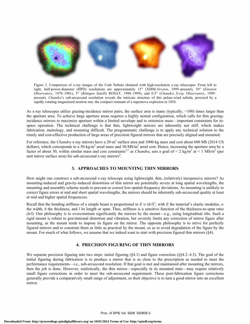
Figure 2right, haObservatpresent). rapidly ro
As x-ray telethe aperture incidence mispace operafabrication, timely and c
For referencdollars), whifactor of abounit mirror s
How might omounting-inmounting ancorrect figurat mid and h
Recall that ththe width, h (h/l). One phrigid mount mounting, afigured mirromount. For m
We separateinitial figuriperformancethen the jobsmall figuregenerally promirror.
. Comparison oalf-power-diametory, 1978–198
Chandra’s subotating magnetiz
escopes utilizearea. To achie
irrors to maximation. The techmetrology, andost-effective p
e, the Chandraich correspondout 30, within surface area) fo
one construct duced and gra
nd assembly schre errors at midhigher spatial fr
he bending stifthe thickness,
hilosophy is tois robust to grs the mount teors and to conmuch of what f
precision figuing during fabe requirements— is done. How
e corrections iovide a compar
of x-ray images eter (HPD) reso1), 5″ (Röntgenb-arcsecond resozed neutron star,
e grazing-incideve large apertmize aperture whnical challend mounting diroduction of la
a x-ray mirrorsds to a 50-kg/m
similar mass aor sub-arcsecon
3. APPROA
a sub-arcseconavity-induced dheme needs to
d and short spatrequencies.
ffness of a sim and l its lengt
o overconstrainravitational disends to imposstrain them as follows, we ass
4. PREC
uring into two brication is to —i.e., sub-arcs
wever, realisticn order to meratively small
of the Crab Neolutions are apn Satellit ROSAolution reveals , the compact rem
dence mirror pature areas requwithin a limite
nge is that thiifficult. The prarge areas of pr
s have a 20-m2
m2 areal mass anand cost constrnd x-ray mirror
ACHES TO
nd x-ray telescdistortions of th
prevent or cortial wavelength
mple beam is prth or span. Thun significantly stortion and vise its figure on
little as practisume that we in
CISION FIGU
steps: initial fiproduce a mi
second resolutially, the thin meet the sub-arcrange of adjust
ebula obtained wpproximately 15AT, 1990–1999)the intricate strmnant of a super
airs, the surfacuires a highly ned envelope anin, lightweighrogrammatic crecision figured
surface area annd 30-M$/m2 araints3,5 as Chars6.
MOUNTING
ope using lighhin mirror are rrect low-spatiahs, the mirrors
roportional to Eus, stiffness isthe mirrors by
ibration, but sen the mirror. Tical by the moundeed want to
URING OF T
figuring (§4.1) rror that is asion. If that goamirror—especcsecond requirtment, so their
with high-resolu5″ (XMM-Newt), and 0.5″ (Chructure of this prnova explosion
ce area is manynested configu
nd to minimize t mirrors are
challenge is to d mirrors that a
nd 1000-kg maareal cost. Henandra, sets a g
G THIN MIR
htweight, thin, potentially sev
al-frequency deshould be inhe
E w (h/l)3, withs a sensitive fuy the mount—everely limits aThe opposite punt, so as to avstart with prec
THIN MIRR
and figure cors close to the al is met and maially in its morement. These
r objective is to
ution x-ray teleston, 1999–presehandra X-ray Opulsar-wind nebin 1054.
y (typically, >uration, which
mass—importinherently noapply any tec
are precisely a
ass and cost abnce, increasinggoal of < 2 kg/
RRORS
(relatively) inevere at long speviations. As merently sub-arc
h E the materiaunction of the t
—e.g., using lonany correctionphilosophy is void degradatiocision figured th
RORS
rrection (§§4.2prescription aaintained after
ounted state—me post-fabricatio turn a good m
copes. From lefent), 10″ (EinsObservatory, 19bula, powered b
100) times largcalls for thin gtant constraint
ot stiff, whichchnical solutioligned and mou
bout 600 M$ (2 the aperture a/m2 at < 1 M$/
expensive mirrpatial wavelengmounting is unlcsecond quality
al’s elastic modthickness-to-spngitudinal ribs.n of mirror figu
to strive for pon of the figurhin mirrors (§4
2–4.3). The goaas needed to m
mounting the may require reion figure cor
mirror into an e
ft to stein 999–by a
ger than grazing-s for in-
h makes n to the unted.
2014 US area by a /m2 (per
rors? As gths, the likely to
y at least
dulus, w pan ratio . Such a ure after perfectly re by the 4).
al of the meet the mirrors, elatively rrections excellent
Proc. of SPIE Vol. 9208 920805-3
Downloaded From: http://proceedings.spiedigitallibrary.org/ on 10/01/2014 Terms of Use: http://spiedl.org/terms

4.1. Initial f
4.1.1. Repli
Replication two advantainsensitive tcompared todesign calls especially if
The predomimission9 andtelescopes tyreplication tuse of ceramstress to avo
Segmented oreplication mNASA’s Nu50″; howeveslumping glahas demonst
Figure 3.panel); m
Even with px-ray optics either static (
4.1.2. Direc
The exquisitgrinding andmirrors that 0.5-m diameincluding hometrology, m
† NuSTAR uprovides a ro
figuring
ication
starts with a pages over directo distortion duo precision figu
for many mirf it is very thin—
inant replicatiod several smalleypically rangeechnologies16,1
mics or other mid distorting th
optics offer admethod for highuSTAR satelliteer, individual mass mirrors thatrated HPD ≈ 8
. Illustration of tmirror-pair half-p
erfect mandrelto HPD > 5″.
(§4.2) or active
ct fabrication
te Chandra mid polishing. Tare nearly an
eter but only aot slumping of machining, and
uses precision obust, rigid mir
precision figurect fabrication (uring figuring uring and polisrrors of the sa—seldom confo
on method for er satellite10,11,
from 15″ to 17—such as plamaterials less
he replica from
dvantages in mh-resolution see28 and sub-or
mirrors are signat could produc8.3″ for a devel
thermal slumpingpower diameters
ls, residual stre. Achieving sue (§4.3) or in c
irrors were prohe Osservatoriorder of magnabout 2-mm thfused-silica tub
d handling; and
machined ribs
rror assembly,
ed mandrel an(§4.1.2). First,
and polishingshing, so it beme size and s
forms perfectly
full-shell x-ray12,13 and sub-or30″, but indiv
asma spray18,19
dense than nim its desired fig
modularity andegmented opticrbital29 missionnificantly bettece a (two-reflelopment modul
g a glass sheet o for state-of-the-
ess in the replicub-arcsecond recombination.
oduced using vio Astronomic
nitude thinner thick. To fabribes into a doub
d ion figuring (
s to stack and it highly overc
d copies the suthe mandrel c
g. Second, repcomes much m
shape. The oney to the shape o
y mirrors is nicrbital14,15 missividual shells m9—can producickel; however
gure.
d in scalabilitycs is glass slumns. The half-poer.† Indeed, NAection) half-powle containing 3
over a precision m-art slumped-gla
cation process esolution will
very precise mco di Brera is than the Chandcate such mirrble-cone net sh§4.2.1) to corr
glue layers ofconstrains the m
urface figure ocan be thick-w
plication itself more cost-effece disadvantageof the precisely
ckel electroformions. The half-pmay be as gooce thicker and r, such process
y to very largemping20,21,22,23,24
ower diameterASA Goddard Swer diameter H
3 co-aligned (pr
mandrel to obtaiass mirrors (right
may limit the likely require
metrology and cpursuing dire
dra mirrors31,32
rors, Brera is hape; use of a sect residual low
f segmented mmirrors, distort
onto a complemwalled and ver
is typically anctive to use ree of replicationy figured mandr
ming, used for power diameteod as ≈10″ bethus stiffer fulses must mini
e collecting ar4,25,26,27 (Figurer of the NuSTASpace Flight CHPD ≈ 6″ (Figrimary–second
in a segmented mt panel). [Credits
angular resolupost-replicatio
conventional dect fabrication 2: The fused siadopting an in
special shell suw-frequency er
mirrors into anting the figure
mentary mirrory stiff, thus ren inexpensive plicated mirron is that the rerel
ESA’s XMM-ers of replicatedefore mountingll-replicas thromize residual
reas. The prede 3 left panel), uAR telescope
Center is now rgure 3 right pandary) mirror pa
mirror substrate s: GSFC/Zhang]
ution of thin reon figure corre
direct fabricatioof full-cylinde
ilica mirrors arnnovative appupport structurerrors.
n assembly. Whfrom its free st
or. It has elatively process rs if the eplica—
-Newton d-nickel g. Other ough the
internal
ominant used for is about egularly nel) and
airs30.
(left ]
eplicated ection—
on—i.e., er x-ray re about
proach—e during
hile this tate.
Proc. of SPIE Vol. 9208 920805-4
Downloaded From: http://proceedings.spiedigitallibrary.org/ on 10/01/2014 Terms of Use: http://spiedl.org/terms
pm44 42 00 02 04
100
50
0
42 00 02 04 24 42 00 02 04
-115 -10 -5 0 5 10 15 -10 -5 0 5 10 15 S5 10 0 5 10 15Azimuth (degree) E Azimuth (degree) P Azimuth (degree)
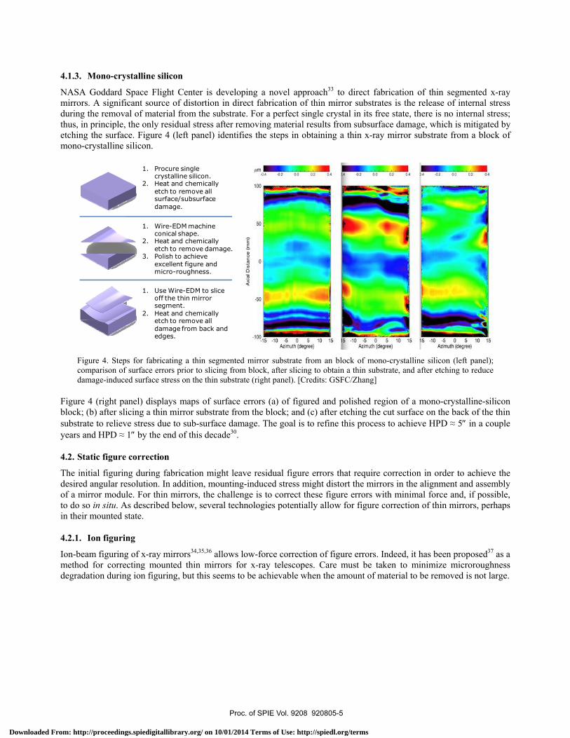
4.1.3. Mono-crystalline silicon
NASA Goddard Space Flight Center is developing a novel approach33 to direct fabrication of thin segmented x-ray mirrors. A significant source of distortion in direct fabrication of thin mirror substrates is the release of internal stress during the removal of material from the substrate. For a perfect single crystal in its free state, there is no internal stress; thus, in principle, the only residual stress after removing material results from subsurface damage, which is mitigated by etching the surface. Figure 4 (left panel) identifies the steps in obtaining a thin x-ray mirror substrate from a block of mono-crystalline silicon.
Figure 4. Steps for fabricating a thin segmented mirror substrate from an block of mono-crystalline silicon (left panel); comparison of surface errors prior to slicing from block, after slicing to obtain a thin substrate, and after etching to reduce damage-induced surface stress on the thin substrate (right panel). [Credits: GSFC/Zhang]
Figure 4 (right panel) displays maps of surface errors (a) of figured and polished region of a mono-crystalline-silicon block; (b) after slicing a thin mirror substrate from the block; and (c) after etching the cut surface on the back of the thin substrate to relieve stress due to sub-surface damage. The goal is to refine this process to achieve HPD ≈ 5″ in a couple years and HPD ≈ 1″ by the end of this decade30.
4.2. Static figure correction
The initial figuring during fabrication might leave residual figure errors that require correction in order to achieve the desired angular resolution. In addition, mounting-induced stress might distort the mirrors in the alignment and assembly of a mirror module. For thin mirrors, the challenge is to correct these figure errors with minimal force and, if possible, to do so in situ. As described below, several technologies potentially allow for figure correction of thin mirrors, perhaps in their mounted state.
4.2.1. Ion figuring
Ion-beam figuring of x-ray mirrors34,35,36 allows low-force correction of figure errors. Indeed, it has been proposed37 as a method for correcting mounted thin mirrors for x-ray telescopes. Care must be taken to minimize microroughness degradation during ion figuring, but this seems to be achievable when the amount of material to be removed is not large.
1. Procure single crystalline silicon.
2. Heat and chemically etch to remove all surface/subsurface damage.
1. Wire-EDM machine conical shape.
2. Heat and chemically etch to remove damage.
3. Polish to achieve excellent figure and micro-roughness.
1. Use Wire-EDM to slice off the thin mirror segment.
2. Heat and chemically etch to remove all damage from back and edges.
Proc. of SPIE Vol. 9208 920805-5
Downloaded From: http://proceedings.spiedigitallibrary.org/ on 10/01/2014 Terms of Use: http://spiedl.org/terms

4.2.2. Diffe
Rather than effectively fideposits a cothe surface, tthe sputterinbe correctedand then pro
Figure 5.
NASA Marsincidence mprofile that c
Figure 6correct suat a varia
In using diffbimorph effeavoid unwan
erential deposi
removing matfilling in valleyoating onto thethe mirror tran
ng target. The s in a given run
ogresses to narr
. Differential dep
shall Space Fligmirrors. Initial tclosely matche
. Test results fourface errors on able rate to produ
ferential deposifect. Thus, an inted deformatio
ition
terial to correcys rather than ae mirror surfacnslates at a posiselected width n. Typically, thrower slits to co
position to corre
ght Center is dtests are quite s the targeted p
or differential dea mirror. In this
uce the desired p
ition to correctimportant aspeon of thin mirro
ct the surface abrading the hie, preferentiallition-dependenof the slit in th
he process startorrect shorter s
ect figure errors o
developing thispromising: Fi
profile, which w
eposition, demons test, nickel is sprofile. [Credits:
t the figure of aect of this reseors.
figure of a miills. Figure 5 illy filling in lownt rate, such thahe sputtering mts with a wide-spatial wavelen
on a mirror’s sur
s process41,42 toigure 6 shows would represen
nstrating the capputtered through: MSFC/Kilaru]
a thin mirror, aearch is to con
irror, differentllustrates this “w regions of that low regions
mask determine-slit run to corrngth errors.
rface. [Credits:
o correct the suthat the proce
nt the profile n
pability for achieh a 5-mm-wide s
any coating strntrol and to mi
tial deposition3
“additive machhe surface. Basof the surface
es the shortest rect longer spa
MSFC/Kilaru]
urface figure ofess can indeed
needed to corre
eving the coatinslit onto a glass
ress could defoinimize coatin
38,39,40 adds mahining” processsed upon metrospend more tispatial scales
atial wavelengt
f light-weight gd achieve a dect surface erro
ng profile needesubstrate, transla
orm the mirror ng stresses, in
aterial—s, which ology of me over that can th errors
grazing-eposition rs.
d to ated
due to a order to
Proc. of SPIE Vol. 9208 920805-6
Downloaded From: http://proceedings.spiedigitallibrary.org/ on 10/01/2014 Terms of Use: http://spiedl.org/terms

4.2.3. Coat
Most x-ray mentioned inbimorph effeimportant obadhesion arestress all dep
On the otherangle and cuby other filmtranslating sl
4.2.4. Diffe
Rather than introduces colocation26,49,
Figure 7.
The MassacLaboratory, integrated stamplitude ofmodulus. Immicroroughn
Figure 8upon ion[Credits:
ing stress
mirrors utilizen the descriptiect. Thus, obtabjective in de
e also importanpend upon the d
r hand, preciseurvature—usingms47,48 depositelit, similar to th
erential ion im
using ions to ompressive strdifferential in
. Depiction of fig
husetts Institufor figure cor
tress upon ion f correction ac
mportantly, the ness (Figure 8 r
. Studies of ion n energy and flue MIT/Chalifoux
e an optical coion of differenaining low-streepositing filmsnt objectives indeposition para
ely controlled cg the bimorph ed onto the suhat used for dif
mplantation
correct the surress near a subduced stress ca
gure correction u
ute of Technolrrection of thinenergy and flu
chievable, at a research has aright panel).
implantation foence (left panel)]
oating on the ntial depositioness coatings—bs onto thin x-n depositing opameters and su
coating stress ceffect47. These
ubstrate. Correfferential depo
rface through strate’s surfacean in principle
using differentia
ogy is developn x-ray mirroruence (Figure 8given spatial w
also shown tha
or figure correcti); relative insens
figured substrn, any stress inby optimization-ray mirrors43,4
ptical coatings. urface propertie
can be used to e errors may bcting shorter ssition (§4.2.2)
erosive ion-bee. By controllicorrect small f
al ion implantatio
ping differentirs. Thus far, th8 left panel), wwavelength, deat the ion impla
ion of thin x-raysitivity of surfac
ate in order ton the coating wn of deposition44,45,46. AchievOf course, mi
es of the substr
correct long-se intrinsic to thspatial-frequen.
eam figuring (§ing exposure ofigure errors th
on. [Credits: MIT
ial ion implanhis research h
which is the relependent upon antation does n
y mirrors, showie microroughne
o enhance the will distort a tn parameters o
ving low micricroroughness, rate.
patial-wavelenhe fabricated s
ncy errors wou
§4.2.1), differef the surface to
hrough the bim
T/Chalifoux]
ntation at its Shas characterizlevant parametthe substrate’
not significant
ing dependence ss to ion implan
x-ray reflectathin mirror duor by annealingoroughness anadhesion, and
ngth errors—e.substrate or intuld require a p
ential ion implo ions as a fun
morph effect (Fi
Space Nanoteched the dependter for determins thickness andly degrade the
of integrated stntation (right pan
ance. As ue to the g—is an nd good d coating
.g., cone troduced precision
lantation nction of igure 7).
hnology dence of ning the d elastic
e surface
tress nel).
Proc. of SPIE Vol. 9208 920805-7
Downloaded From: http://proceedings.spiedigitallibrary.org/ on 10/01/2014 Terms of Use: http://spiedl.org/terms
NMI'IwonoMIN
IONMOWO88888
4.3. Active f
Ultimately, istatic figure mounting, thmirror assem(§4.2); howe
There are twactuation (SNof the mirrorof the mirrocorrection is
Here we briemirrors. Thidescriptions
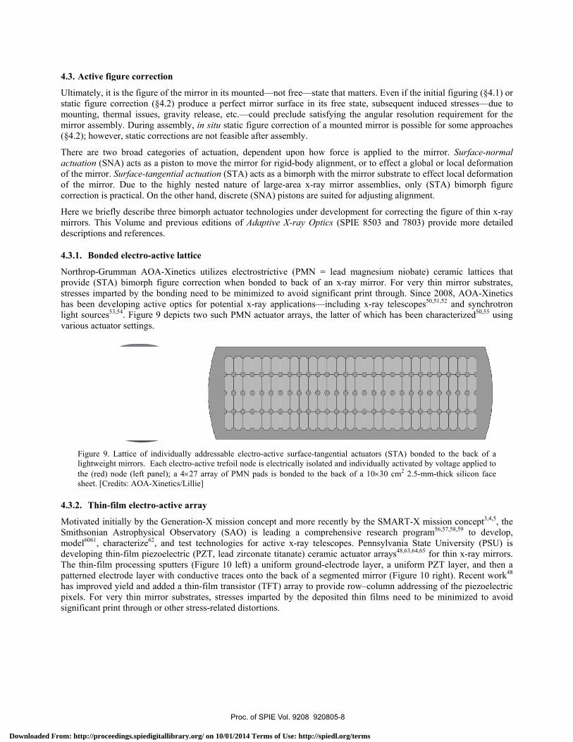
4.3.1. Bond
Northrop-Grprovide (STstresses imphas been delight sourcesvarious actua
Figure 9lightweigthe (red)sheet. [C
4.3.2. Thin
Motivated inSmithsonianmodel6061, chdeveloping tThe thin-filmpatterned elehas improvepixels. For vsignificant p
figure correcti
it is the figure ocorrection (§4
hermal issues, mbly. During aever, static corr
wo broad cateNA) acts as a r. Surface-tangor. Due to the practical. On t
efly describe this Volume andand references
ded electro-act
rumman AOAA) bimorph fiarted by the bveloping activs53,54. Figure 9 ator settings.
. Lattice of indght mirrors. Eac node (left pane
Credits: AOA-Xin
-film electro-a
nitially by the n Astrophysicaharacterize62, thin-film piezom processing sectrode layer wd yield and advery thin mirrorint through or
ion
of the mirror in4.2) produce agravity releas
assembly, in sitrections are no
egories of actupiston to move
gential actuatioe highly nestethe other hand
hree bimorph ad previous edits.
tive lattice
A-Xinetics utiliigure correctioonding need to
ve optics for pdepicts two su
dividually addresch electro-activeel); a 4×27 arraynetics/Lillie]
active array
Generation-X al Observatoryand test techn
oelectric (PZT,sputters (Figurwith conductivdded a thin-filmor substrates, r other stress-re
n its mounted—a perfect mirrose, etc.—couldtu static figuret feasible after
uation, depende the mirror foon (STA) acts ad nature of la, discrete (SNA
actuator technotions of Adapt
izes electrostrion when bondeo be minimize
potential x-ray uch PMN actu
ssable electro-ace trefoil node is ey of PMN pads
mission concey (SAO) is lenologies for ac, lead zirconatere 10 left) a une traces onto t
m transistor (TFstresses imparelated distortio
—not free—staor surface in itd preclude satie correction of r assembly.
dent upon howr rigid-body alas a bimorph warge-area x-rayA) pistons are s
ologies under dtive X-ray Opt
ictive (PMN =ed to back of ed to avoid sig
applications—uator arrays, th
ctive surface-tanelectrically isola
is bonded to th
ept and more reeading a compctive x-ray tele titanate) ceraniform groundthe back of a sFT) array to prrted by the depons.
ate that mattersts free state, sisfying the anga mounted mir
w force is applignment, or to
with the mirror y mirror assemsuited for adjus
development fotics (SPIE 850
= lead magnean x-ray mirr
gnificant print —including x-rhe latter of whi
ngential actuatoated and individuhe back of a 10×
ecently by the prehensive reslescopes. Pennamic actuator a-electrode layesegmented mirrovide row–coposited thin fi
. Even if the insubsequent indgular resolutiorror is possible
plied to the mo effect a globa
substrate to efmblies, only (sting alignmen
for correcting th03 and 7803) p
sium niobate)ror. For very tthrough. Sinceay telescopes5
ich has been c
rs (STA) bondeually activated b×30 cm2 2.5-mm
SMART-X msearch programnsylvania Statearrays48,63,64,65 er, a uniform Prror (Figure 10lumn addressin
ilms need to b
nitial figuring (duced stresses—on requiremente for some app
mirror. Surfaceal or local defoffect local defo(STA) bimorphnt.
he figure of thprovide more
ceramic lattithin mirror sube 2008, AOA-X0,51,52 and sync
characterized50,
ed to the back oy voltage appliem-thick silicon f
mission conceptm56,57,58,59 to de University (Pfor thin x-ray PZT layer, and
0 right). Recentng of the piezo
be minimized t
(§4.1) or —due to t for the proaches
e-normal ormation ormation h figure
hin x-ray detailed
ces that bstrates, Xinetics chrotron ,55 using
of a
ed to face
t3,4,5, the develop, PSU) is mirrors. d then a t work48 oelectric to avoid
Proc. of SPIE Vol. 9208 920805-8
Downloaded From: http://proceedings.spiedigitallibrary.org/ on 10/01/2014 Terms of Use: http://spiedl.org/terms
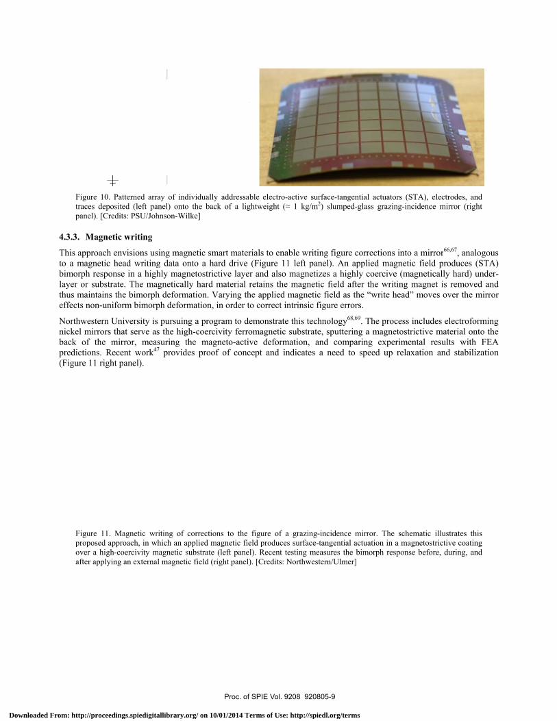
Figure 1traces depanel). [C
4.3.3. Magn
This approacto a magnetibimorph resplayer or subthus maintaieffects non-u
Northwesternnickel mirroback of thepredictions. (Figure 11 ri
Figure 1proposedover a hiafter app
0. Patterned arreposited (left paCredits: PSU/Joh
netic writing
ch envisions usic head writingponse in a higstrate. The mans the bimorphuniform bimorp
rn University isrs that serve a
e mirror, meaRecent work4
ight panel).
1. Magnetic wrd approach, in wigh-coercivity mlying an externa
ray of individuaanel) onto the bhnson-Wilke]
sing magnetic sg data onto a hly magnetostr
agnetically harh deformation.ph deformation
s pursuing a prs the high-coe
asuring the m47 provides pro
riting of correctwhich an applied magnetic substraal magnetic field
ally addressable back of a lightw
smart materialhard drive (Firictive layer and material reta. Varying the an, in order to c
rogram to demorcivity ferroma
magneto-active oof of concept
tions to the figumagnetic field p
ate (left panel). Rd (right panel). [C
electro-active sweight (≈ 1 kg/m
s to enable wriigure 11 left pnd also magneains the magneapplied magnetorrect intrinsic
onstrate this teagnetic substradeformation,
t and indicates
ure of a grazinproduces surfacRecent testing mCredits: Northwe
surface-tangentiam2) slumped-gla
iting figure corpanel). An appetizes a highly etic field after tic field as the c figure errors.
echnology68,69. ate, sputtering
and comparins a need to sp
ng-incidence mire-tangential actu
measures the bimestern/Ulmer]
al actuators (STass grazing-inci
rrections into aplied magnetic
coercive (magthe writing m“write head” m
The process ina magnetostricng experimentpeed up relaxa
rror. The schemuation in a magnmorph response
TA), electrodes, dence mirror (r
a mirror66,67, anfield produce
gnetically hardmagnet is remo
moves over th
ncludes electroctive material otal results wiation and stab
matic illustratesnetostrictive coabefore, during,
and
right
nalogous s (STA)
d) under-ved and e mirror
forming onto the th FEA ilization
this
ating and
Proc. of SPIE Vol. 9208 920805-9
Downloaded From: http://proceedings.spiedigitallibrary.org/ on 10/01/2014 Terms of Use: http://spiedl.org/terms
5. SUMMARY
Creating a large-aperture-area (≈ 3 m2) sub-arcsecond x-ray telescope will be technologically and programmatically challenging. Achieving sub-arcsecond imaging with the thin, lightweight (≈ 1 kg/m2 areal density) mirrors needed to satisfy mass and envelope constraints requires significant advancement of technologies. Further, to be programmatically viable, areal costs for mirror fabrication and alignment and assembly must be relatively low (≈ 1 M$/m2) for the hundreds of m2 of precision mirror surface areas needed for a grazing-incidence telescope with 3-m2 aperture area.
Several technologies are under development for producing precision figured, thin x-ray mirrors. These include processes for initial figuring during fabrication and for post-fabrication figure correction—either static or active. Some methods are suitable for in situ figure correction of mirrors in their mounted state. Achieving precise and stable alignment and figure control may entail active (in-space adjustable) x-ray optics.
Proc. of SPIE Vol. 9208 920805-10
Downloaded From: http://proceedings.spiedigitallibrary.org/ on 10/01/2014 Terms of Use: http://spiedl.org/terms
REFERENCES
1 O'Dell, S. L., & Weisskopf, M. C., “The role of project science in the Chandra X-ray Observatory”, SPIE 6271, 07
14pp (2006). 2 Weisskopf, M. C., Tananbaum, H. D., Van Speybroeck, L. P., & O'Dell, S. L., “Chandra X-ray Observatory (CXO):
overview”, SPIE 4012, 2-16 (2000). 3 Schwartz, D. A., Aldcroft, T. L., Bookbinder, J. A., Cotroneo, V., Davis, W. N., Forman, W. R., Freeman, M. D.,
McMuldroch, S., Reid, P., Tananbaum, H., Vikhlinin, A., Trolier-McKinstry, S., Wilke, D., & Johnson-Wilke, R., “The square meter arcsecond resolution x-ray telescope: SMART-X”, SPIE 8503, 08 8pp (2012).
4 Vikhlinin, A., Reid, P., Tananbaum, H., Schwartz, D. A., Forman, W. R., Jones, C., Bookbinder, J., Cotroneo, V., Trolier-McKinstry, S., Burrows, D., Bautz, M. W., Heilmann, R., Davis, J., Bandler, S. R., Weisskopf, M. C., & Murray, S. S., “SMART-X: Square Meter Arcsecond Resolution x-ray Telescope”, SPIE 8443, 16 12pp (2012).
5 Schwartz, D. A., Allured, R., Bookbinder, J. A., Cotroneo, V., Forman, W. R., Freeman, M. D., McMuldroch, S., Reid, P. B., Tananbaum, H., Vikhlinin, A. A., Johnson-Wilke, R. L., Trolier-McKinstry, S. E., Wilke, R. H. T., Gubarev, M. V., Kolodziejczak, J. J., O’Dell, S. L., & Ramsey, B. D., “Technology requirements for a square meter, arcsecond resolution telescope for x-rays: the SMART-X mission”, SPIE 9208, 06 8pp (2014).
6 O'Dell, S. L., Aldcroft, T. L., Atkins, C., Button, T. W., Cotroneo, V., Davis, W. N., Doel, P., Feldman, C. H., Freeman, M. D., Gubarev, M. V., Johnson-Wilke, R. L., Kolodziejczak, J. J., Lillie, C. F., Michette, A. G., Ramsey, B. D., Reid, P. B., Rodriguez Sanmartin, D., Saha, T. T., Schwartz, D. A., Trolier-McKinstry, S. E., Ulmer, M. P., Wilke, R. H. T., Willingale, R., & Zhang, W. W., “Toward active x-ray telescopes II”, SPIE 8503, 07 15pp (2012).
7 O'Dell, S. L., Atkins, C., Button, T. W., Cotroneo, V., Davis, W. N., Doel, P., Feldman, C. H., Freeman, M. D., Gubarev, M. V., Kolodziejczak, J. J., Michette, A. G., Ramsey, B. D., Reid, P. B., Rodriguez Sanmartin, D., Saha, T. T., Schwartz, D. A., Trolier-McKinstry, S., Wilke, R. H. T., Willingale, R., & Zhang, W. W., “Toward active x-ray telescopes”, SPIE 8147, 1Q 14pp (2011).
8 O'Dell, S. L., Brissenden, R. J., Davis, W. N., Elsner, R. F., Elvis, M. S., Freeman, M. D., Gaetz, T., Gorenstein, P., Gubarev, M. V., Jerius, D., Juda, M., Kolodziejczak, J. J., Murray, S. S., Petre, R., Podgorski, W., Ramsey, B. D., Reid, P. B., Saha, T., Schwartz, D. A., Trolier-McKinstry, S., Weisskopf, M. C., Wilke, R. H. T., Wolk, S., & Zhang, W. W., “High-resolution x-ray telescopes”, SPIE 7803, 0H 19pp (2010).
9 de Chambure, D., Laine, R., van Katwijk, K., Kletzkine, P., Valenzuela, A., Grisoni, G., Canali, M., Hofer, S., Tock, J. P., Domken, I., Stockman, Y., Hansen, H., Leonard, M., Aschenbach, B., & Braeuninger, H. W., “Lessons learned from the development of the XMM optics”, SPIE 3737, 2-17 (1999).
10 Friedrich, P., Bräuninger, H., Budau, B., Burkert, W., Burwitz, V., Dennerl, K., Eder, J., Freyberg, M., Gaida, R., Hartner, G., Menz, B., Pfeffermann, E., Predehl, P., Rohé, C., & Schreib, R., “Development and testing of the eROSITA mirror modules”, SPIE 8443, 1S 8pp (2012).
11 Burwitz, V., Friedrich, P., Bräuninger, H., Budau, B., Burkert, W., Eder, J., Freyberg, M., Hartner, G., Pfeffermann, E., Predehl, P., Arcangeli, L., Borghi, G., Borroni, A., Citterio, O., Ferrario, I., Grisoni, G., Marioni, F., Ritucci, A., Rossi, M., Valsecchi, G., & Vernani, D., “Development and testing of the eROSITA mirror modules”, SPIE 8147, 08 6pp (2011).
12 Gubarev, M., Ramsey, B., O'Dell, S. L., Elsner, R., Kilaru, K., McCracken, J., Pavlinsky, M., Tkachenko, A., Lapshov, I., Atkins, C., & Zavlin, V., “Development of mirror modules for the ART-XC instrument aboard the Spectrum-Roentgen-Gamma mission”, SPIE 8861, 0K 6pp (2013).
13 Burrows, D. N., Hill, J. E., Nousek, J. A., Wells, A. A., Chincarini, G., Abbey, A. F., Beardmore, A. P., Bosworth, J., Bräuninger, H. W., Burkert, W., Campana, S., Capalbi, M., Chang, W., Citterio, O., Freyberg, M. J., Giommi, P., Hartner, G. D., Killough, R., Kittle, B., Klar, R., Mangels, C., McMeekin, M., Miles, B. J., Moretti, A., Mori, K., Morris, D. C., Mukerjee, K., Osborne, J. P., Short, A. D. T., Tagliaferri, G., Tamburelli, F., Watson, D. J., Willingale, R., & Zugger, M. E., “The Swift X-Ray Telescope”, SPIE 5165, 201-216 (2004).
14 Atkins, C., Ramsey, B., Kilaru, K., Gubarev, M., O'Dell, S., Elsner, R., Swartz, D., Gaskin, J., & Weisskopf, M., “X-ray optic developments at NASA's MSFC”, SPIE 8777, 0W 9pp (2013).
Proc. of SPIE Vol. 9208 920805-11
Downloaded From: http://proceedings.spiedigitallibrary.org/ on 10/01/2014 Terms of Use: http://spiedl.org/terms
15 Ramsey, B. D., Elsner, R. F., Engelhaupt, D., Gubarev, M. V., Kolodziejczak, J. J., O'Dell, S. L., Speegle, C. O., &
Weisskopf, M. C., “The development of hard x-ray optics at MSFC”, SPIE 5168, 129-135 (2004). 16 Hudec, R., Pina, L., Inneman, A. V., Ticha, H., Brozek, V., Zentkova, M., Zentko, A., & Chylek, T., “Lightweight
x-ray optics for future space missions”, SPIE 4851, 656-665 (2003). 17 Citterio, O., Ghigo, M., Mazzoleni, F., Pareschi, G., Parodi, G., Braeuninger, H. W., Burkert, W., & Hartner, G. D.,
“Development of soft and hard x-ray optics for astronomy: progress report II and considerations on material properties for large-diameter segmented optics of future missions”, SPIE 4496, 23-40 (2002).
18 Romaine, S., Bruni, R., Choi, B., Gorenstein, P., Jensen, C., Ramsey, B., Rosati, R., & Sampath, S., “Development of light weight replicated x-ray optics”, SPIE 8861, 0U 7pp (2013).
19 Ulmer, M. P., Graham, M. E., Vaynman, S., Farber, M., Echt, J. I., Varlese, S. J., Emerson, G., & Baker, D., “Advances in the use of plasma spraying for the fabrication of lightweight x-ray optics”, SPIE 5533, 93-98 (2004).
20 Ghigo, M., Proserpio, L., Basso, S., Citterio, O., Civitani, M. M., Pareschi, G., Salmaso, B., Sironi, G., Spiga, D., Tagliaferri, G., Vecchi, G., Zambra, A., Parodi, G., Martelli, F., Gallieni, D., Tintori, M., Bavdaz, M., Wille, E., Ferrario, I., & Burwitz, V., “Slumping technique for the manufacturing of a representative x-ray grazing incidence mirror module for future space missions”, SPIE 8884, 1Q 14pp (2013).
21 Zhang, W. W., Biskach, M. P., Blake, P. N., Bly, V. T., Carter, J. M., Chan, K. W., Gaskin, J. A., Hong, M., Hohl, B. R., Jones, W. D., Kolodziejczak, J. J., Kolos, L. D., Mazzarella, J. R., McClelland, R. S., McKeon, K. P., Miller, T. M., O'Dell, S. L., Riveros, R. E., Saha, T. T., Schofield, M. J., Sharpe, M. V., & Smith, H. C., “High resolution and high throughput x-ray optics for future astronomical missions”, SPIE 8861, 0N 13pp (2013).
22 Civitani, M., Ghigo, M., Basso, S., Proserpio, L., Spiga, D., Salmaso, B., Pareschi, G., Tagliaferri, G., Burwitz, V., Hartner, G., Menz, B., Bavdaz, M., & Wille, E., “Direct hot slumping and accurate integration process to manufacture prototypal x-ray optical units made of glass”, SPIE 8861, 10 24pp (2013).
23 Zhang, W. W., Biskach, M. P., Blake, P. N., Chan, K. W., Evans, T. C., Hong, M. L., Jones, W. D., Kolos, L. D., Mazzarella, J. M., McClelland, R. S., O'Dell, S. L., Saha, T. T., & Sharpe, M. V., “Lightweight and high angular resolution x-ray optics for astronomical missions”, SPIE 8147, 0K 12pp (2011).
24 Winter, A., Breunig, E., Burwitz, V., Friedrich, P., Hartner, G., Menz, B., & Proserpio, L., “Light-weight glass mirror systems for future x-ray telescopes”, SPIE 8861, 0Q 10pp (2013).
25 Pareschi, G., Basso, S., Bavdaz, M., Citterio, O., Civitani, M. M., Conconi, P., Gallieni, D., Ghigo, M., Martelli, F., Parodi, G., Proserpio, L., Sironi, G., Spiga, D., Tagliaferri, G., Tintori, M., Wille, E., & Zambra, A., “IXO glass mirrors development in Europe”, SPIE 8147, 0L 12pp (2011).
26 Chalifoux, B., Heilmann, R. K., & Schattenburg, M. L., “Shaping of thin glass X-ray telescope mirrors using air bearing slumping and ion implantation”, SPIE 9144, 4D 7pp (2014).
27 Sung, E., Chalifoux, B., Schattenburg, M. L., & Heilmann, R. K., “Non-touch thermal air-bearing shaping of x-ray telescope optics”, SPIE 8861, 0R 8pp (2013).
28 Zhang, W. W., “Manufacture of mirror glass substrates for the NuSTAR mission”, SPIE 7437, 0N 11pp (2009). 29 Koglin, J. E., Chen, C. M. H., Chonko, J. C., Christensen, F. E., Craig, W. W., Decker, T. R., Hailey, C. J., Harrison,
F. A., Jensen, C. P., Madsen, K. K., Pivovaroff, M. J., Stern, M., Windt, D. L., & Ziegler, E., “Hard x-ray optics: from HEFT to NuSTAR”, SPIE 5488, 856-867 (2004).
30 Zhang, W. W., Biskach, M. P., Bly, V. T., Carter, J. M., Chan, K. W., Gaskin, J. A., Hong, M., Hohl, B. R., Jones, W. D., Kolodziejczak, J. J., Kolos, L. D., Mazzarella, J. R., McClelland, R. S., McKeon, K. P., Miller, T. M., O'Dell, S. L., Riveros, R. E., Saha, T. T., Schofield, M. J., Sharpe, M. V., & Smith, H. C., “Affordable and lightweight high-resolution x-ray optics for astronomical missions”, SPIE 9144, 15 9pp (2014).
31 Civitani, M. M., Citterio, O., Ghigo, M., Mattaini, E., Pareschi, G., & Parodi, G., “Thin monolithic glass shells for future high angular resolution and large collecting area x-ray telescope”, SPIE 8884, 1R 11pp (2013).
32 Citterio, O., Civitani, M. M., Pareschi, G., Basso, S., Campana, S., Conconi, P., Ghigo, M., Mattaini, E., Moretti, A., Parodi, G., & Tagliaferri, G., “Thin fused silica optics for a few arcsec angular resolution and large collecting area x-ray telescope”, SPIE 8861, 0V 14pp (2013).
Proc. of SPIE Vol. 9208 920805-12
Downloaded From: http://proceedings.spiedigitallibrary.org/ on 10/01/2014 Terms of Use: http://spiedl.org/terms
33 Riveros, R. E., Bly, V. T., Kolos, L. D., McKeon, K. P., Mazzarella, J. R., Miller, T. M., & Zhang, W. W.
“Fabrication of single-crystal silicon mirror substrates for x-ray astronomical missions”, SPIE 9144, 45 6 pp (2014). 34 Umetsu, H., Sakai, Y., Tsuru, T., & Yamamoto, M., “Evaluation of ion milled soft x-ray multilayer mirrors for
reflection wavefront correction”, JVSJ 53, 368-370 (2010). 35 Gawlitza, P., Braun, S., Dietrich, G., Menzel, M., Schädlich, S., & Leson, A., “Ion beam sputtering of x-ray
multilayer mirrors”, SPIE 7077, 03 11pp (2008). 36 Geril, N., Grigely, L. J., Wilson, S. R., & Goela, J. S., “Thin-shell replication of grazing incidence (Wolter type I)
SiC mirrors”, SPIE 2478, 215-227 (1995). 37 Gailly, P., de Chambure, D., Collette, J. P., Jamar, C. A. J., Laine, R., Mazy, E., Medart, P., & Stockman, Y., “New
process for x-ray mirror image quality improvement”, SPIE 4782, 46-57 (2002). 38 Ablett, J. M., Kao, C. C., & Lunt, A., “The design and performance of an x-ray micro-focusing system using
differentially deposited elliptical mirrors at the National Synchrotron Light Source”, RScI 73, 3464-3468 (2002). 39 Ice, G. E., Chung, J.-S., Tischler, J. Z., Lunt, A., & Assoufid, L., “Elliptical x-ray microprobe mirrors by differential
deposition”, RScI 71, 2635-2639 (2000). 40 Cai, Z., Yun, W., & Plag, P., “Parameter optimization for producing an elliptical surface from a spherical surface by
differential deposition”, SPIE 2516, 52-68 (1995). 41 Kilaru, K., Ramsey, B. D., Gubarev, M. V., & Gregory, D. A., “Differential deposition technique for figure
corrections in grazing-incidence x-ray optics”, OptEn 50, 106501 6pp (2011). 42 Kilaru, K., Ramsey, B. D., Gubarev, M. V., Gaskin, J. A., O'Dell, S. L., & Zhang, W., “Differential deposition to
correct surface figure deviations in astronomical grazing-incidence x-ray optics”, SPIE 8147, 0X 8pp (2011). 43 Chan, K.-W., Sharpe, M., Zhang, W., Kolos, L., Hong, M., McClelland, R., Hohl, B., Saha, T., & Mazzarella, J.,
“Coating thin mirror segments for lightweight x-ray optics”, SPIE 8861, 0X 12pp (2013). 44 Chan, K.-W., Zhang, W. W., Windt, D., Hong, M.-L., Saha, T., McClelland, R., Sharpe, M., & Dwivedi, V. H.,
“Reflective coating for lightweight x-ray optics”, SPIE 8443, 3S 11pp (2012). 45 Windt, D. L., “Reduction of stress and roughness by reactive sputtering in W/B4C multilayer films”, SPIE 6688, 0R
10pp (2007). 46 Heilmann, R. K., Monnelly, G. P., Mongrard, O., Butler, N., Chen, C. G., Cohen, L. M., Cook, C. C., Goldman, L.
M., Konkola, P. T., McGuirk, M., Ricker, G. R., & Schattenburg, M. L., “Novel methods for shaping thin-foil optics for x-ray astronomy”, SPIE 4496, 62-72 (2002).
47 Ulmer, M. P., Wang, X., Knapp, P., Cao, J., Cao, Y., Karian, T., Grogans, S., Graham, M. E., Vaynman, S., & Yao, Y., “Comparisons of the deflections of magnetically smart films on alloy of NiCo and glass substrates”, SPIE 9208, 08 11pp (2014).
48 Johnson-Wilke, R. L., Wilke, R. H. T., Wallace, M., Ramirez, J. I., Prieskorn, Z., Nikoleyczik, J., Cotroneo, V., Allured, R., Schwartz, D. A., McMuldroch, S., Reid, P. B., Burrows, D. N., Jackson, T. N., & Trolier-McKinstry, S., “ZnO thin film transistors and electronic connections for adjustable x-ray mirrors: SMART-X telescope”, SPIE 9208, 09 9pp (2014).
49 Chalifoux, B., Sung, E., Heilmann, R. K., & Schattenburg, M. L., “High-precision figure correction of x-ray telescope optics using ion implantation”, SPIE 8861, 0T 13pp (2013).
50 Lillie, C. F., Egan, R., Landers, F., Cavaco, J., Kevin Ezzoc, K., “Test results for an AOA-Xinetics grazing incidence x-ray deformable mirror”, SPIE 9208, 0C 9pp (2014).
51 Lillie, C. F., Pearson, D. D., Cavaco, J. L., Plinta, A. D., & Wellman, J. A., “Adaptive x-ray optics development at AOA-Xinetics”, SPIE 8503, 0B 12pp (2012).
52 Lillie, C., Pearson, D., Plinta, A., Metro, B., Lintz, E., Shropshire, D., & Danner, R., “Adaptive grazing incidence optics for the next generation of x-ray observatories”, SPIE 7803, 0Q 7pp (2010).
53 Brooks, A., Wirth, A., Lintz, E., & Cavaco, J., “Design and fabrication of a high precision x-ray deformable mirror”, SPIE 9208, 0E 7pp (2014).
Proc. of SPIE Vol. 9208 920805-13
Downloaded From: http://proceedings.spiedigitallibrary.org/ on 10/01/2014 Terms of Use: http://spiedl.org/terms
54 Poyneer, L. A., Pardini, T., McCarville, T., Palmer, D., & Brooks, A., “Control of a 45-cm long x-ray deformable
mirror with either external or internal metrology”, SPIE 9208, 0F 11pp (2014). 55 Marathe, S., Shi, X., Kujala, N., Wojcik, M. J., Khounsary, A., Qian, J., Macrander, A., & Assoufid, L.,
“Development of single grating x-ray Talbot interferometer as a feedback loop sensor element of an adaptive x-ray mirror system”, SPIE 9208, 0D 7pp (2014).
56 Reid, P. B., Aldcroft, T. L., Cotroneo, V., Davis, W., Johnson-Wilke, R. L., McMuldroch, S., Ramsey, B. D., Schwartz, D. A., Trolier-McKinstry, S., Vikhlinin, A., & Wilke, R. H. T., “Development status of adjustable grazing incidence optics for 0.5 arc second x-ray imaging”, SPIE 8861, 1Q 8pp (2013).
57 Reid, P. B., Aldcroft, T. L., Cotroneo, V., Davis, W., Johnson-Wilke, R. L., McMuldroch, S., Ramsey, B. D., Schwartz, D. A., Trolier-McKinstry, S., Vikhlinin, A., & Wilke, R. H. T., “Technology development of adjustable grazing incidence x-ray optics for sub-arc second imaging”, SPIE 8443, 0T 8pp (2012).
58 Cotroneo, V., Davis, W. N., Marquez, V., Reid, P. B., Schwartz, D. A., Johnson-Wilke, R. L., Trolier-McKinstry, S. E., & Wilke, R. H. T., “Adjustable grazing incidence x-ray optics based on thin PZT films”, SPIE 8503, 09 10pp (2012).
59 Reid, P. B., Davis, W., Schwartz, D. A., Trolier-McKinstry, S., & Wilke, R. H. T., “Technology challenges of active x-ray optics for astronomy”, SPIE 7803, 0I 9pp (2010).
60 Aldcroft, T. L., Schwartz, D. A., Reid, P. B., Cotroneo, V., & Davis, W. N., “Simulating correction of adjustable optics for an x-ray telescope”, SPIE 8503, 0F 9pp (2012).
61 Schwartz, D. A., Cotroneo, V., Davis, W., Freeman, M., & Reid, P., “Adjustable x-ray optics: correction for gravity-induced figure errors”, SPIE 8147, 1S 9pp (2011).
62 Cotroneo, V., Davis, W. N., Reid, P. B., Schwartz, D. A., Trolier-McKinstry, S., & Wilke, R. H. T., “Adjustable grazing incidence x-ray optics: measurement of actuator influence functions and comparison with modeling”, SPIE 8147, 1R 12pp (2011).
63 Wilke, R. H. T., Johnson-Wilke, R. L., Cotroneo, V., Davis, W. N., Reid, P. B., Schwartz, D. A., & Trolier-McKinstry, S., “Sputter deposition of PZT piezoelectric films on thin glass substrates for adjustable x-ray optics”, ApOpt 52, 3412-3419 (2013).
64 Johnson-Wilke, R. L., Wilke, R. H. T., Cotroneo, V., Davis, W. N., Reid, P. B., Schwartz, D. A., & Trolier-McKinstry, S., “Improving yield of PZT piezoelectric devices on glass substrates”, SPIE 8503, 0A 9pp (20120).
65 Wilke, R. H. T., Trolier-McKinstry, S., Reid, P. B., & Schwartz, D. A., “PZT piezoelectric films on glass for Gen-X imaging”, SPIE 7803, 0O:1-10 (2010).
66 Ulmer, M. P., Graham, M. E., Vaynman, S., Cao, J., & Takacs, P. Z., “Deformable mirrors for x-ray astronomy and beyond”, SPIE 8076, 05:1-10 (2011).
67 Ulmer, M. P., Graham, M. E., Vaynman, S., Cao, J., & Takacs, P. Z., “Magnetic smart material application to adaptive x-ray optics”, SPIE 7803, 09:1-11 (2010).
68 Ulmer, M. P., Wang, X., Cao, J., Savoie, J., Bellavia, B., Graham, M. E., & Vaynman, S., “Progress report on using magneto-strictive sputtered thin films to modify the shape of a x-ray telescope mirror”, SPIE 8503, 0C 8pp (2012).
69 Wang, X., Cao, J., Ulmer, M. P., Graham, M. E., Vaynman, S., Savoie, J., & Bellavia, B., “Comparing theory with experimental data in studying the deformation of magnetically smart films deposited on nickel and glass substrates”, SPIE 8503, 0D 8pp (2012).
Proc. of SPIE Vol. 9208 920805-14
Downloaded From: http://proceedings.spiedigitallibrary.org/ on 10/01/2014 Terms of Use: http://spiedl.org/terms