toward engineering simulation in the petrochemical ... · observation • innovation and...
TRANSCRIPT

"Toward Engineering Simulation in the Petrochemical Industry: From Discovery to End-Use"
"Toward Engineering Simulation in the Petrochemical Industry: From Discovery to End-Use"
© 2008 ANSYS, Inc. All rights reserved. 1 ANSYS, Inc. Proprietary
Ahmad H. Haidari, Ph.D.Global Industry DirectorProcess, Energy and Power
Ahmad H. Haidari, Ph.D.Global Industry DirectorProcess, Energy and Power

Observation
• Innovation and engineering drive many of future technologies in energy production, processing, and end use.
• Recent years has shown a broad application and accelerating rate of adoption of engineering Simulation tools
– Coupling of reservoir and well bore
– Drilling and production
– Storage and Transport
© 2008 ANSYS, Inc. All rights reserved. 2 ANSYS, Inc. Proprietary
– Refining and processing
– End use design for example:• Formulation and engine performance
– Material handling and processing• Extrusion
• blow molding
• The rapid growth and a broader acceptance are due:
– Advanced computational and numerical techniques,
– Enhanced physical models
– Usability improvements,

Objectives
• Brief overview of ANSYS activities in Petrochemical
– Review the breath of the engineering simulation applications
– Provide an update on some of the underlying technologies • Meshing
• FSI
© 2008 ANSYS, Inc. All rights reserved. 3 ANSYS, Inc. Proprietary
• FSI
• Particulate flows
• In-cylinder-combustion
• Parallel processing
– Provide examples of work underway at ANSYS for Advanced Petrochemical applications
– Flow assurance• Slug flow
• Sand and water management

Sample examples Drilling/Production
© 2008 ANSYS, Inc. All rights reserved. 4 ANSYS, Inc. Proprietary

Sample examples Refining/Processing
© 2008 ANSYS, Inc. All rights reserved. 5 ANSYS, Inc. Proprietary

Offshore Hydrodynamics
– Wave impact
– Sloshing
– Transport
• Offshore Structures
– Fixed• Steel Jackets
• Concrete
– Floating• FPSOs
• SPARS
• Semi-Submersibles
© 2008 ANSYS, Inc. All rights reserved. 6 ANSYS, Inc. Proprietary
• Semi-Submersibles
– Risers
– Ship • Design
• Offloading
• Shielding
– Applications• Mooring systems
• Lifting operation – AMOG
• jacket launch
Transportation of Spar Truss on Heavy Lift Vessel

Petrochemical Industry
Advanced Technology Needs
• Selected list:
– Complex geometry and grid motion
– Wide range of numerics
– Advanced physics• Combustion and Reaction
© 2008 ANSYS, Inc. All rights reserved. 7 ANSYS, Inc. Proprietary
• Combustion and Reaction
• Multiphase
• Turbulence-Chemistry
– Multi-scale
– Multiphyscis
– HPC and Parallel computing

Recent Software Development
Activities
• Meshing
– Wrapping Technology
– Immersed boundary condition
• Multiphase
© 2008 ANSYS, Inc. All rights reserved. 8 ANSYS, Inc. Proprietary
• Multiphase
• In-Cylinder Combustion
• Parallel processing

ANSYS Technology Update
Meshing, Geometry
– Wrapping Technology• Clean up complex geometry
• Accelerate meshing
– Immersed boundary condition• Simulations @ non-body
conforming meshes
© 2008 ANSYS, Inc. All rights reserved. 9 ANSYS, Inc. Proprietary
conforming meshes
• Reduced time for geometry & mesh preparation
• Boundary conditions via reconstruction schemes
Oil Rig; Courtesy of Lilleaker Consulting AS and Inocean-Marotec AS

• Mesh morphing
– Cylindrical component displacement option
– Mesh quality histogram in ‘out’ file
• One-way and two way
ANSYS Technology update
Fluid-Structure-Interaction
© 2008 ANSYS, Inc. All rights reserved. 10 ANSYS, Inc. Proprietary
• One-way and two way coupling
• Surface loads
– Forces
– Energy fluxes
• Volume loads
– Temperature

ANSYS Technology Update
Internal Combustion Engines
• Setup of multiple configurations
• Re-meshing
• Combustion
• Particle tracking & sprays
Wall films
© 2008 ANSYS, Inc. All rights reserved. 11 ANSYS, Inc. Proprietary
• Wall films
• ;

CFX - Internal Combustion Engines
© 2008 ANSYS, Inc. All rights reserved. 12 ANSYS, Inc. Proprietary

Multi-Phase – Euler-Lagrange
0.08
0.1
Hiroyasu&Kadota, case 1
• Validation report
– Collaboration with Robert
Bosch
• Spray break-up models
– Primary – Huh & Gosman
– Secondary
© 2008 ANSYS, Inc. All rights reserved. 13 ANSYS, Inc. Proprietary
Time [s]
Pen
etr
atio
nD
ep
th[m
]
0.0005 0.001 0.0015 0.002 0.00250
0.02
0.04
0.06
0.08
ExperimentHuhBlob + TABHuh +TAB

CFX - Multi-Phase – Euler-Lagrange
© 2008 ANSYS, Inc. All rights reserved. 14 ANSYS, Inc. Proprietary

Multi-Phase, Multi-fluid VOF
• Multi-fluid free surface flow
model (VoF)
– Separate velocities for each
phase
– Explicit interface tracking
scheme
• Multi-fluid free surface flow
© 2008 ANSYS, Inc. All rights reserved. 15 ANSYS, Inc. Proprietary
• Multi-fluid free surface flow
model (VoF)
– Heterogeneous model
– Separate velocities for each
phase
– Explicit interface tracking
scheme
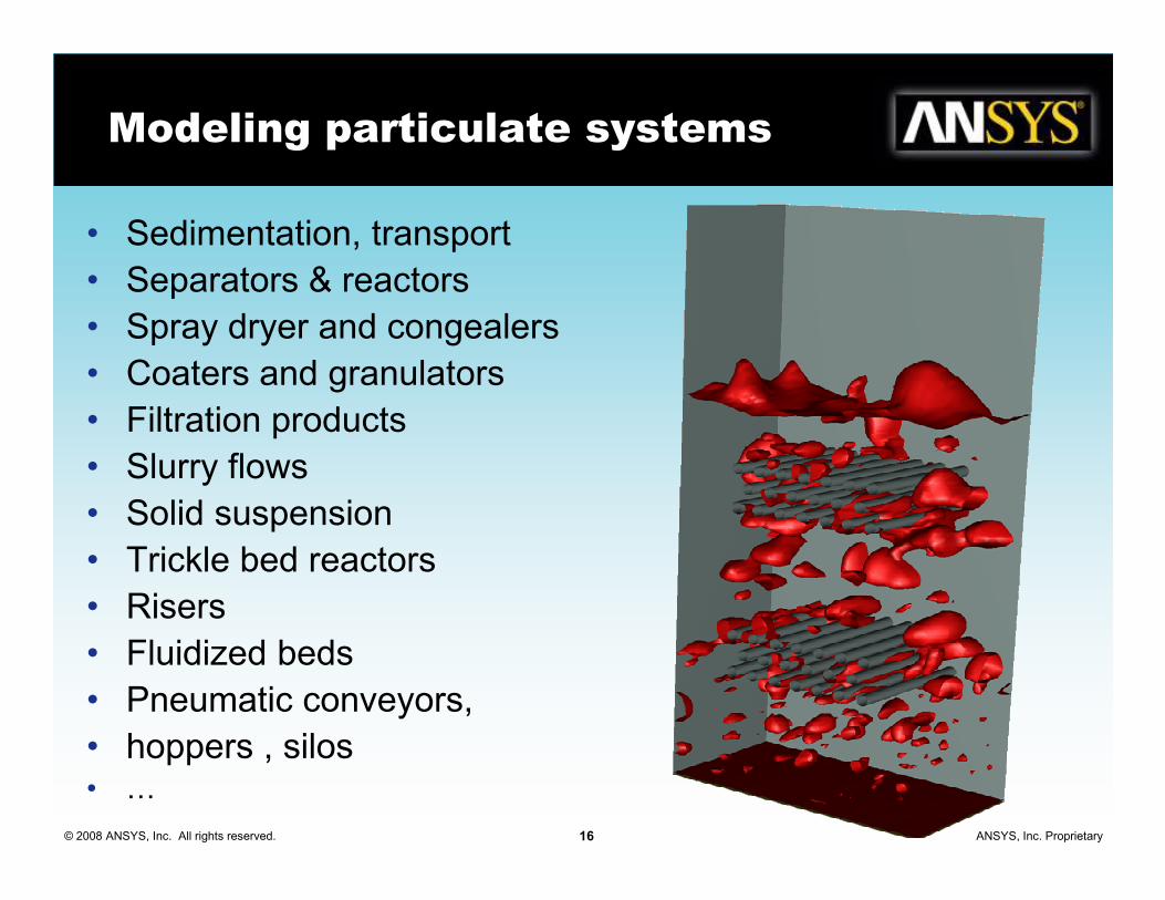
Modeling particulate systems
• Sedimentation, transport
• Separators & reactors
• Spray dryer and congealers
• Coaters and granulators
• Filtration products
• Slurry flows
© 2008 ANSYS, Inc. All rights reserved. 16 ANSYS, Inc. Proprietary
• Slurry flows
• Solid suspension
• Trickle bed reactors
• Risers
• Fluidized beds
• Pneumatic conveyors,
• hoppers , silos• G

Diluted vs. Dense Flow
t12/tcol
104
102
100
44--waywaycouplingcoupling
22--waywaycouplingcoupling
11--waywaycouplingcoupling
Particlesreduce
turbulence
Particlesenhance turbulence
negligibleeffect on turbulence
102
100
10-2
ττττ12/ττττeddy
© 2008 ANSYS, Inc. All rights reserved. 17 ANSYS, Inc. Proprietary
es10-3 10-110-510-710-2
dilute dense
101102 100(x1-x2)/dp
DiluteDilute DenseDense
Relative motion between Relative motion between particlesparticles LargeLarge SmallSmall
ParticleParticle--particle interactionparticle interaction WeakWeak StrongStrong
Apparent viscosity of the Apparent viscosity of the solid phasesolid phase
ParticleParticle--fluid fluid
interactionsinteractions
ParticleParticle--particle particle
interactioninteraction

Overview of Modeling Approaches
Flow around individual particles
Continuum model
(multi-dimension)
Local averaging
Particle MotionParticle Motion
Fluid MotionFluid Motion
Direct Numerical SimulationDirect Numerical Simulation Eulerian Granular Eulerian Granular
Trajectories of individual particles
© 2008 ANSYS, Inc. All rights reserved. 18 ANSYS, Inc. Proprietary
Concept illustration borrowed from Prof. Tsuji Presentation at WCPT5, April 2006Concept illustration borrowed from Prof. Tsuji Presentation at WCPT5, April 2006
dxdx
dydy
EulerEuler--LagrangianLagrangian
Grid elements
DNS/DEM/MPMDNS/DEM/MPM

Particle Models Available
• Modeling particulate flows have been an area of focus for over a decade current capabilities include:
– Particle Methods
• DPM for dilute phase (steady and time dependent)
• Macroscopic Particle Model (MPM) for large particles
© 2008 ANSYS, Inc. All rights reserved. 19 ANSYS, Inc. Proprietary
for large particles
• Dense-phase discrete particle model (DP-DPM) for dense flows with large size distributions
– Continuous Methods
• Euler-Granular,
• Euler-Granular with Frictional viscosity for dense phase
– Hybrid Methods
• Coupled simulations
• DEM

Comparison of Various ApproachesComparison of Various Approaches
Particle to particle Particle to particle
interactionsinteractions
Coupling Coupling
with cont. with cont.
phasephase
Additional physics Additional physics
& chemistry & chemistry
Particle shape, Particle shape,
size distributionsize distribution
Order of # of Order of # of
particlesparticles
Computation Computation
speed & speed &
parallelizationparallelization
DEMDEM
Direct contact and other forces implementation
None or through ext. CFD code
Not implemented Arbitrary (clustered spheres) shape & distribution
~105 Strongly dependent on # of particles, not parallelized, Rel. slow
DPMDPMCollisions & breakup indirectly; packing limit not accounted
Correlation-based drag force
Coupled with all std. Fluent models, easy to customize
Spherical and ellipsoidal
~106
Very fast, parallelized
Particles are represented Correlation- Coupled with all std. Spherical, arbitrary size No limit on part/ Rel. fast, affected by
© 2008 ANSYS, Inc. All rights reserved. 20 ANSYS, Inc. Proprietary
DPDP--DPMDPM
Particles are represented by clusters, packing limit is maintained
Correlation-based drag force
Coupled with all std. Fluent models, easy to customize
Spherical, arbitrary size distribution available
No limit on part/ clusters (tested up to ~ 2.5x10⁵)
Rel. fast, affected by mesh size & # of particles, parallelized
MPMMPM
Direct contact and other forces implementation
Drag & torque resolved
Further customization possible
Spherical*, arbitrary distribution
~105 Slow, parallel tracking (interactions not parallel)
Euler Euler GranularGranular
Indirect: solid pressure & radial distr., other forces implemented indirectly
Cell-avg. drag, lift & other inter-ph. terms
Coupled with all std. Fluent models; easier to customize
Spherical; Size dist. through population balance
Practically unlimited
Fast, depends on the mesh size & physics only, parallelized
!!! This table is for tentative and qualitative comparison !!! Because of a continuous development, models continue to evolve
*arbitrary shapes being tested

Challenge Problem:
gas-solid Riser
• Expect risers to be a tough
challenge
– Complex multi-scale physics
– Strands, clusters etc.
– May stretch validity of assumptions
© 2008 ANSYS, Inc. All rights reserved. 21 ANSYS, Inc. Proprietary
– May stretch validity of assumptions
of parcels
• Preliminary results show some
promise shown here
• More qualitative validation is
needed

ANSYS Technology Update
Parallel Computing
• Discretization & Solution
– Optimization of equation assembly & solution
– Iteratively bounded advection & transient scheme for turbulence quantities
• Much larger problems are being molded
0
100
200
300
400
500
600
CFX 10 CFX 11 CFX 12
© 2008 ANSYS, Inc. All rights reserved. 22 ANSYS, Inc. Proprietary
molded
• scalability, especially on large clusters
– Example; Opteron/EM64T lnamd64 version
– Currently under testing
• 1 billion cell case
• 700 million cells per processor per core
• Opteron/EM64T lnamd640
20
40
60
80
100
120
140
Tim
e,
s
64-R 64-W 128-R 128-W
Serial
Parallel
111 million cells
Option IB cluster & HP/SFS (IB)

Advanced oil and gas applications
• Flow Assurance
© 2008 ANSYS, Inc. All rights reserved. 23 ANSYS, Inc. Proprietary

ANSYS Focus
Flow Assurance
• Motivation
– The trends in deep and ultradeep production requires
– robust understanding and planning of:• Production Enhancement
• Flow Assurance in increasingly demanding conditions
– Flow Assurance requires a systematic analysis
© 2008 ANSYS, Inc. All rights reserved. 24 ANSYS, Inc. Proprietary
– Flow Assurance requires a systematic analysis including • thermal and hydraulic performance
• multi-phase flow
– Slugging
– Water and Sand management
– hydrates and paraffin or wax precipitation

Produced water
• Produced water is not a product
• For offshore operations, the disposal
– Re-injection to the formation
– Transport onshore.
• produced water is “contaminated” with high salinity, oil and Metal
• Polishing produced water
© 2008 ANSYS, Inc. All rights reserved. 25 ANSYS, Inc. Proprietary
• Polishing produced water
– clarifiers,
– hydrocyclones,
– membrane separation,
– ultraviolet light treatment,
– various separators
• Engineering Simulations tools are used to
– Reduce risk
– Increase ratability of equipment and processes.

Application Focus
Sand Management and Transport
• Sand is often produced out of the reservoir in both onshore and offshore production systems, particularly in reservoirs that have a low formation strength
• Sand production may be continuous, or sudden - as when a gravel pack fails
© 2008 ANSYS, Inc. All rights reserved. 26 ANSYS, Inc. Proprietary
• The sediment consists of finely divided solids that may be drilling mud or sand or scale picked up during the transport of the oil
• Sand deposition could lead to corrosion of the pipeline
• Problem of sand deposition and re-entrainment
– Inclined pipelines, pigging sand plug pipeline

Slurry Flow Regimes
• Slurry flow is classified into different regimes
• The transition between regimes depends on
– Solids concentration
– Velocity
© 2008 ANSYS, Inc. All rights reserved. 27 ANSYS, Inc. Proprietary
– Velocity
– Particle Diameter
– Turbulence
• Mostly derived for high sand concentrations (>1%) and large particle diameter (>100um)
• Typical:
– 5-50 lb sand / 1000 bbl liquid
– USL/USS ~ 50000-500000**Reference: Abulnaga B.E., Slurry systems handbook (2002) Mc-Graw Hill
** Tom Danielson, ConocoPhillips, “Sand Transport
Modeling in Multiphase Pipelines”, OTC-18691, 2007

Study Objectives
• Lack of data on low volume fraction <1vol% and small diameter <50µµµµm
• Validation work using experimental data
– Range of volume fractions
– Range of sand particle diameter
– Different pipeline diameters
© 2008 ANSYS, Inc. All rights reserved. 28 ANSYS, Inc. Proprietary
– Different pipeline diameters
• Gain confidence in modeling methodology and extend approach to:
– Low concentrations and particle diameter
– Pipeline orientation
• Influence of turbulent fluctuations
– Interphase turbulent momentum transfer• Drift velocity
– Volume fraction diffusion

Pressure Drop Validation
• Experimental data from:
– Skudarnov, P.V. et al, 2001. Experimental Investigation of Single-and Double-Species Slurry Transportation in a Horizontal Pipeline. Proc. ANS 9th International Topical Meeting on Robotics and Remote Systems, Seattle, WA
• Experimental Conditions
– Horizontally straight pipeline length, L = 1.4 m
© 2008 ANSYS, Inc. All rights reserved. 29 ANSYS, Inc. Proprietary
– Horizontally straight pipeline length, L = 1.4 m
– Pipe I.D. = 0.0221 m
– Silica sand–water slurry
• Water density ρ = 998.2 kg/m3
• Sand density ρ = 2381 kg/m3
• Sand diameter dp = 0.000097–0.00011 m
– Inlet sand concentration = 20 vol%
• Assumed fully developed, fully mixed inlet slurry flow
• Mesh size: 140K cells

Pressure Drop Validation
• Good agreement
with experimental
data
• The influence of the 2500
3000
3500
4000
4500
Me
an
Slu
rry P
res
su
re G
rad
ien
t, P
a/m
Skudarnov et al, 2001
Newitt et al, 1955
FLUENT CFD - Schiller Drag
FLUENT CFD - Wen & Yu Drag
© 2008 ANSYS, Inc. All rights reserved. 30 ANSYS, Inc. Proprietary
• The influence of the
solids volume
fraction is captured
with the Wen & Yu
drag model
• Flow regime –
heterogeneous
transport
0
500
1000
1500
2000
0.5 1.0 1.5 2.0 2.5 3.0
Mean Slurry Velocity, m/s
Me
an
Slu
rry P
res
su
re G
rad
ien
t, P
a/m

Predicting Solids Dispersion
• Analysis of the
following variables:
– Slurry velocity
– Solids concentration
– Solid particle diameter
Solids
conc.,
vol%
34 27 27 34
Particle dia.
dp (µµµµm)120 120 120 370
© 2008 ANSYS, Inc. All rights reserved. 31 ANSYS, Inc. Proprietary
– Solid particle diameter
– Mesh: 0.5 million cells
dp (µµµµm)
Velocity
(m/s)
6.00
06.000 2.000 6.000
Source: V. Matousek, Pressure drops and flow patterns in sand-mixture
pipes, Experimental Thermal and Fluid Science 26 (2002) 693–702
150 mm diameter pipeWell-mixed
Slurry
(Sand/Water)
Test section
6.55 m 3 m
ρsand= 2650 kg/m3

Influence of Particle Concentration
• Flow regime is nearly homogeneous
– V >> Vcritical
• Solids almost uniformly distributed across the pipe diameter
0.6
0.8
1
Y / D
Fluent CFD: Cv = 0.27
Fluent CFD: Cv = 0.34
Expts., Matousek, 2002
© 2008 ANSYS, Inc. All rights reserved. 32 ANSYS, Inc. Proprietary
• Experimental measurements mostly in the center of the pipe
– Good agreement with simulation results
• Drop in slurry concentration near pipe wall
0
0.2
0.4
0 0.1 0.2 0.3 0.4 0.5 0.6
Solids Volume Fraction
Vslurry = 6 m/s
dp = 120 µm

0.6
0.8
1
Y / D
Influence of Particle Diameter
• Flow regime is heterogeneous transport
– V >> Vcritical
• Solids concentration increases near the pipe bottom with the Vslurry = 6 m/s
© 2008 ANSYS, Inc. All rights reserved. 33 ANSYS, Inc. Proprietary
0
0.2
0.4
0 0.1 0.2 0.3 0.4 0.5 0.6
Solids Volume Fraction
Y / D
Fluent CFD: dp = 120 um
Matousek, 2002 (dp = 120 um)
Fluent CFD: dp = 370 um
Matousek, 2002 (dp = 370 um)
bottom with the increase in particle diameter
• Experimental measurements in good agreement with simulation results
• Drop in slurry concentration near pipe wall
Vslurry = 6 m/s
Cs = 34 vol%

Influence of Slurry Velocity
• Flow regime is
heterogeneous transport
– V > Vcritical
• Solids concentration profile
changes with drop in velocity0.8
1
Fluent CFD: Vs = 2 m/s, Cs=27%
Fluent CFD: Vs = 6 m/s, Cs=27%
Fluent CFD: Vs = 2 m/s, Cs=34%
Fluent CFD: Vs = 6 m/s, Cs=34%
Matousek, 2002 (Vs = 6 m/s, Cs = 34%)
© 2008 ANSYS, Inc. All rights reserved. 34 ANSYS, Inc. Proprietary
• Increase in slurry
concentration near pipe wall
at lower velocity
• As the granular temperature
increases, particles are
pushed from the wall
• Dissipation from collision is
insufficient to counteract the
higher values
dp = 120 µm
0
0.2
0.4
0.6
0.8
0 0.1 0.2 0.3 0.4 0.5 0.6
Solids Volume Fraction
Y / D
dp = 120 µm

Summary Sand Management
• Eulerian granular multiphase was applied to model
dilute and dense slurry flows in pipes
• Good agreement was obtained for the pressure
gradient and the solids distribution
• The influence of turbulence on the interphase
© 2008 ANSYS, Inc. All rights reserved. 35 ANSYS, Inc. Proprietary
• The influence of turbulence on the interphase
momentum exchange (Eulerian) is required for this
class of problems
• For dilute flows, incorporating the influence of
turbulent dispersion in the volume fraction equation
maybe required
• Further studies - pipe orientation, re-entrainment,
flow regime with stationary bed, polydispersed solids

Application Focus
Predicting Slug Flow
• Multiphase pipeline analysis for flow assurance
– Hydrodynamic slugging
– Terrain slugging
© 2008 ANSYS, Inc. All rights reserved. 36 ANSYS, Inc. Proprietary

Hydrodynamic slugging
Experimental Setup
• Experiments conducted in WASP at Imperial College
– No influence of downstream conditions on upstream gas/liquid flow rates
• 78 mm diameter x 37 m pipe
© 2008 ANSYS, Inc. All rights reserved. 37 ANSYS, Inc. Proprietary
• 0.5 m long inlet section with separate gas/liquid inlets and splitter plate
• Air/Water system
– vSG = 4.64 m/s
– vSL = 0.61 m/s
– Inlet pressure = 1.15 bar
• Expected flow regime is slug flow

Hydrodynamic slugging
Numerical Setup
• Numerics
– NITA with Fractional step
– Default Solver Controls
– PRESTO! and First-order discretization
– Green gauss cell-based gradient solver
– Realizable k-epsilon
– Geo-reconstruct
© 2008 ANSYS, Inc. All rights reserved. 38 ANSYS, Inc. Proprietary
– Geo-reconstruct
• Phase Interaction
– Surface tension = 0.072 N/m
• Calculation time on HPC queue (Opteron/IB)
– Global Courant Number = 1
– Variable time step ~ 1e-5 – 1e-4s
– Solution time = 6 s / iteration – 265475 iterations/87.09 seconds real time on 16 CPUs
– Solution time = ~80 hours of CPU time per second of real flow time
• Mesh Size 1.03 Million

Hydrodynamic Slugging with VOF
Interface height at 53.23 s
© 2008 ANSYS, Inc. All rights reserved. 39 ANSYS, Inc. Proprietary
Snapshot of interface at 53.23 s

Comparison of Height Profiles
SLUG
Top of pipe
© 2008 ANSYS, Inc. All rights reserved. 40 ANSYS, Inc. Proprietary
∆tslug passage~ 5 seconds
VOF
Experimental
• Characteristic gradual rise in interface height
followed by rapid drop is reproduced by the
VOF model
• Lower dips towards the end of the pipe
reproduced
• Stratified-wavy interface near inlet is
reproduced

Slug Frequency
• Experimentally determined
slug frequency varies along
length of pipe though slugs
formed by ~5m remain
relatively intact to the end of
the pipe
© 2008 ANSYS, Inc. All rights reserved. 41 ANSYS, Inc. Proprietary
the pipe
– Slug frequency ~ 0.2 – 0.3 s-1
– Range of time interval
between slugs of 1 – 10
seconds
• The VOF simulation shows
similar range of slug interval
and frequency

Recap
• Engineering Simulation tools are being used
to solve a broad range of applications in the
petrochemical and related industries.
• A selected set of related software
© 2008 ANSYS, Inc. All rights reserved. 42 ANSYS, Inc. Proprietary
• A selected set of related software
development capabilities we reviewed.
Highlighting, meshing, FSI, multiphase, and
parallel processing
• A review of application of CFD to predicating
slugs and sand transport was presented

Acknowledgements
• Lanre Oshinowo
• Georg Scheuerer
• Chris Wolfe
© 2008 ANSYS, Inc. All rights reserved. 43 ANSYS, Inc. Proprietary