toward a second generation fuel efficient supersonic cruise aircraft design ... · pdf...
TRANSCRIPT
TOWARD A SECOND GENERATION FUEL EFFICIENT SUPERSONIC CRUISE AIRCRAFT
DESIGN CHARACTERISTICS AND FEASIBILITY
Frank D. Neumann Boeing Commercial Airplane Company
SUMMARY
Studies at Boeing in recent years have focused on the definition, analysis, and evaluation of the blended wing-fuselage concept. Although blended wing configurations have been examined before, this fresh approach was initiated to reduce airplane drag in response to the increasing need for improved fuel efficiency. Studies to date not only indicate that this type of wing-fuselage integration is conducive to an efficient low fuel consuming airplane with a smaller, less expensive propulsion system that meets noise goals, but also is structurally efficient and practical. This paper reviews the basis and objec- tives of design improvement studies. Design changes that lead to improved aerodynamic and structural efficiency are presented. Practical design constraints and approaches for a blended wing-fuselage are discussed, as well as the integration of the configuration that leads to aerodynamic and structural efficiency. Highlighted are new approaches used to provide for structural efficiency, airline/passenger acceptance, passenger evacuation, and subsystem integration. Results of full-scale passenger cabin mock-up evaluations are presented showing the feasibility of the concept.
BACKGROUND
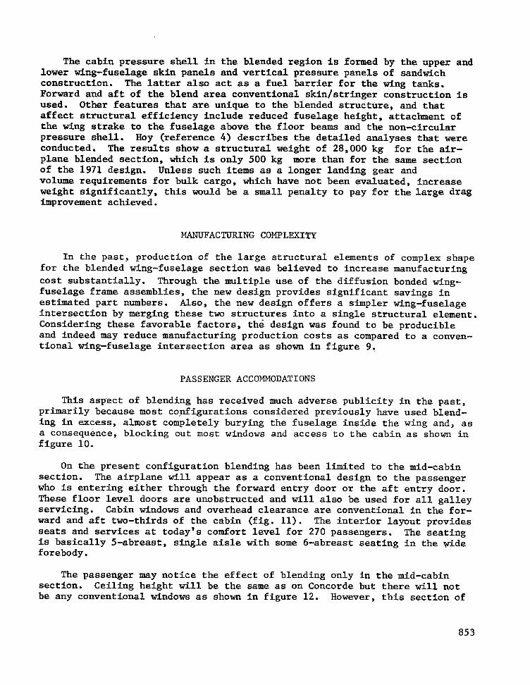
The construction of two prototype U.S. SST airplanes by Boeing was well under way at the time the program was cancelled in 1971. The design charact- eristics of these prototype aircraft represented the culmination of more than a decade of engineering and technology development, analysis and experimental testing on a grand scale. The results of this program and the DOT technology follow-on program have provided an extensive, invaluabie and accessible data base. This base is a logical starting point for useful development work towards definition of future advanced supersonic cruise aircraft. Therefore, a small Boeing team, in its technology assessment and design improvement studies, both in-house and under the SCAR program, has departed incrementally from this 1971 design (fig. 1). Studies have focused on improvement in areas where the potential payoff appeared greatest and where the results could'be validated with confidence. Airplane size was kept fixed while the benefits of incremental design improvements have been measured in terms of increased range or fuel efficiency.
849
https://ntrs.nasa.gov/search.jsp?R=19770011093 2018-05-13T18:50:50+00:00Z
II llllllllIl I I
DESIGN OBJECTIVES
The design objectives for future supersonic cruise aircraft have been changed greatly by external factors which are much different now than they were for both Concorde and the original U.S. SST design. Goodmanson in reference 1 has dealt 'with this concept of a moving target. Among these factors fuel efficiency is now paramount to meet the imperatives of an energy- conscious era and to counter the ever-increasing burden of fuel cost on operating economics.
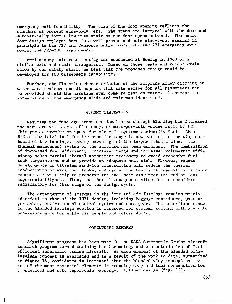
Transatlantic range is no longer enough and transpacific capability of over 7500 km (4000 N. Mi.) is required to create new non-stop city pairs, offering more travelers the ultimate benefit of supersonic flight. This points to the need for much improved aerodynamic efficiency for supersonic cruise in addition to other advances in propulsive efficiency, structural efficiency, plus those improvements that can be effected by advances in systems technology. In 1973 a vigorous program was initiated at Boeing to reduce the supersonic drag of the 1971 design. Looking at the supersonic drag buildup in figure 2, wave drag at transonic speed accounts for 40% of the total drag while during cruise it accounts for about 25%. Substantial reductions in wave drag were.sought. These would also cut down the engine size and weight which severely compromised the performance of the 1971 design.
REDUCING SUPERSONIC WAVE DRAG
During initial design studies drag reduction features were incorporated into the 1971 wing. These are shown in figure 3:
. Thickness to chord ratio of the outboard wing was reduced effec- tively by changing from a biconvex airfoil to a modified double wedge shape, reducing maximum thickness while retaining structural depth at front spar and rear spar.
. Weight/drag trades indicated that further modifications in span- wise thickness distribution favored a thinner outboard wing with lower drag.
. Increased strake size is a very powerful drag reduction feature. Incorporation of an Malpha" limiter into the flight control system will make possible this larger strake which increases aircraft pitch-up tendency at low speed. The main wing was sheared aft to retain aerodynamic balance.
. Aft shearing of the wing further reduced wave drag and also effec- tively increased the chord of the wing structural box, and, since the engines were not moved, reduced the engine overhang. These wing geometry revisions improved wing flutter characteristics which were marginal on the 1971 design.
850
Detail structural analyses showed that this newer low drag wing with improved aeroelastic characteristics actually weighs less than the 1971 prototype wing.
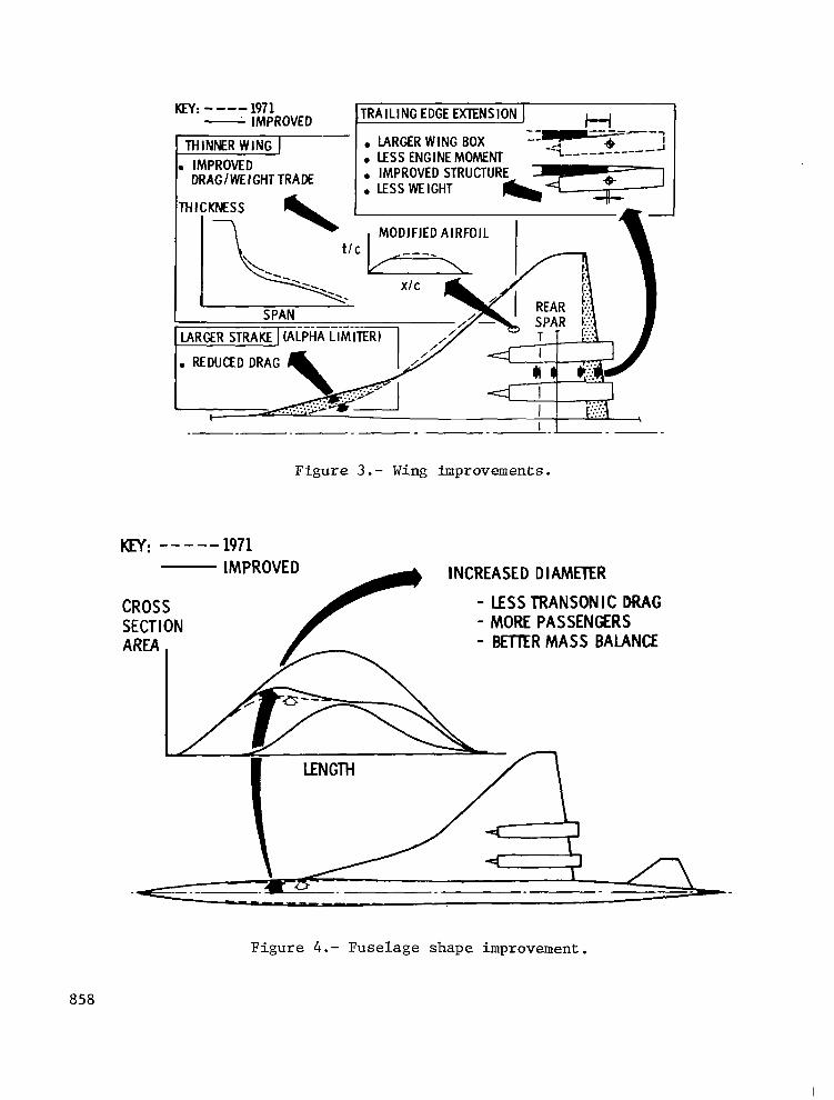
. Further studies have shown that favorable trades between transonic and supersonic drag are possible by area-ruling the.fuselage at a Mach number lower than cruise. This, in effect, increases volume of the forebody. The larger forebody allows more passengers to be carried efficiently, balancing the weight of the aft-mounted engines as shown in figure 4.
These initial configuration improvement studies reduced transonic drag by 13% and cruise drag by 6%. The effect on engine/airframe matching was favorable, allowing smaller, more efficient multicycle engines to be used yet provide for satisfactory supersonic climb and acceleration of the airplane as shown by Vachal (ref. 2).
WING-FUSELAGE BLENDING
Further drag reductions were seen possible through a blended wing-fuse- lage arrangement. Using this concept airplane cross-sectional area and total volume are reduced, hence reducing supersonic drag.
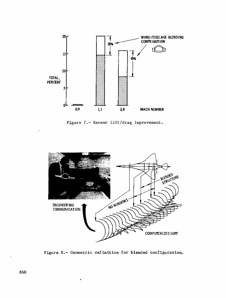
The most effective approach was found to be in the minimizing of the combined height of wing and fuselage in the aircraft midsection. This was done by raising the upper surface of the wing from below the passenger cabin floor to the middle of the cabin and then using a wrap-around structural arrangement for the wing carry-through structure as shown in figure 5. Lowering the combined wing-fuselage height to a practical minimum in this manner reduced the cross section by an area equivalent to the proverbial barn door. A 5-abreast passenger seating arrangement was maintained as well as sufficient structural depth for transfer of the wing loads across the top and bottom of the fuselage. The new area distribution of the mid-fuselage section compares to the old distribution as shown in figure 6. Blending brings total lift/drag improvement to 20% transonically and to 18% during supersonic cruise as shown in figure 7.
The corresponding improvement in airplane range (or fuel efficiency) is 30% when considering only the effects of reduced drag and engine size. The configuration that evolved during two years of detailed design and trade studies retains many of the features of the 1971 design such as the forebody, aft body, landing gear, and empennage, along with the wing improvements des- cribed above. Sensitivity studies showed that these components, for which an extensive data base either existed or, in the case of the wing, was being developed in parallel, could be integrated efficiently with the new, blended section (ref. 3).
851
THE QUESTION OF FEASIBILITY
Wing-fuselage blending has been applied successfully to modern military aircraft like B-l and F-16, increasing both their aerodynamic and structural efficiency. On a passenger airplane these benefits are somewhat more diffi- cult to realize, because what's good aerodynamically and structurally, in this case can affect the passenger. Previous commercial blended designs were not seriously considered and the reasons may be categorized as follows:
. The technology was not available to solve inherent problems effectively, i.e., in the structures area.
. Never before were the problems associated with blending worked in enough depth to ,find satisfactory solutions.
. The need to make the concept work has been amplified by increased fuel prices.
. In the past arbitrary ground rules were established that ruled out blending, i.e., everybody needs a window!
To evaluate feasibility and practicality during the present effort, each of the following critical areas of concern was studied in considerable depth and satisfactory solutions were found and/or demonstrated:
Structural efficiency and weight
Manufacturing complexity and cost
Passenger appeal, comfort and outside viewing
Passenger evacuation
Volume limitations
STRUCTURAL EFFICIENCY
Two factors are decisive in making the blended structure react the wing and fuselage bending moments efficiently. First, a gradual transition must be provided between wing and fuselage in the highly loaded wing inspar region (7 meters long) to avoid excessive kick loads. To satisfy this requirement for a gradual transition, the inboard wing thickness was in- creased substantially. Acceptable aft airfoil closure angles were maintained by extending the wing trailing edge aft, creating the planform fillet which is characteristic of blended configurations as shown in figure 8. Second, the skin covers must be of thick sandwich construction to prevent buckling and in order to work effectively with the deep wing-fuselage frames, which are continuous across the blend area (see figure 5). The technology to manu- facture the required, large,heavy gauge, thick sandwich panels has been developed recently.
852
The cabin pressure shell in the blended region is formed by the upper and lower wing-fuselage skin panels and vertical pressure panels of sandwich construction. The latter also act as a fuel barrier for the wing tanks. Forward and aft of the blend area conventional skin/stringer construction is used. Other features that are unique to the blended structure, and that affect structural efficiency include reduced fuselage height, attachment of the wing strake to the fuselage above the floor beams and the non-circular pressure shell. Hoy (reference 4) describes the detailed analyses that were conducted. The results show a structural weight of 28,000 kg for the air- plane blended section, which is only 500 kg mOre than for the same section of the 1971 design. Unless such items as a longer landing gear and volume requirements for bulk cargo, which have not been evaluated, increase weight significantly, this would be a small penalty to pay for the large drag improvement achieved.
MANUFACTURING COMPLEXITY
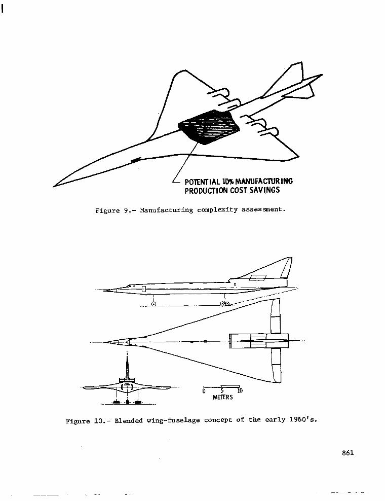
In the past, production of the large structural elements of complex shape for the blended wing-fuselage section was believed to increase manufacturing cost substantially. Through the multiple use of the diffusion bonded wing- fuselage frame assemblies, the new design provides significant savings in estimated part numbers. Also, the new design offers a simpler wing-fuselage intersection by merging these two structures into a single structural element. Considering these favorable factors, the design was found to be producible and indeed may reduce manufacturing production costs as compared to a conven- tional wing-fuselage intersection area as shown in figure 9:
PASSENGER ACCOMMODATIONS
This aspect of blending has received much adverse publicity in the past, primarily because most configurations considered previously have used blend- ing in excess, almost completely burying the fuselage inside the wing and, as a consequence, blocking out most windows and access to the cabin as shown in figure 10.
On the present configuration blending has been limited to the mid-cabin section. The airplane will appear as a conventional design to the passenger who is entering either through the forward entry door or the aft entry door. These floor level doors are unobstructed and will also be used for all galley servicing. Cabin windows and overhead clearance are conventional in the for- ward and aft two-thirds of the cabin (fig. 11). The interior layout provides seats and services at today's comfort level for 270 passengers. The seating is basically 5-abreast, single aisle with some 6-abreast seating in the tide forebody.
The passenger may notice the effect of blending only in the mid-cabin section. Ceiling height will be the same as on Concorde but there will not be any conventional windows as shown in figure 12. However, this section of
853

the airplane can be designed to be very spacious and appealing. This has been demonstrated through a full-scale mock-up as shown in figures 13 and 14, The effect of spaciousness was created through the effective use of sculptured panels, recessed between wing-fuselage frames, spaced at 1 meter intervals. Innovative' lighting of these recessed panels in the sidewalls and ceiling creates an open atmosphere. Overhead luggage bins are also effectively recessed between the deep fuselage frames similar to the new wide body look of the popular Boeing 727 trijet interior. Raceways for the major systems are integrated into the lower sidewalls with functional armrests for the "window" seats. The result is a pleasant, acceptable, modern cabin interior as confirmed by numerous visitors to the full-scale mock-up.
OUTSIDE VIEWING
Airline/passenger acceptance of a partially windowless cabin will probably be controversial, even though indirect vision systems could offer the passen- ger outside viewing far superior to that offered by small windows shielded by the large wing of a supersonic airliner. For example, viewing sensors for such systems could be located at the extremities of the airplane, thereby giving excellent field of viewing to the passengers and the flight crew.
One of the limiting factors in previously proposed indirect viewing systems has been the excessive space required by the cathode ray tube display system in the passenger cabin. With the new technology of solid state thin screen television, this constraint has been greatly reduced.
These thin television screens would be inserted into the back of the passenger seats, illustrated in figure 15, or elsewhere. View selection could be multiple, giving the passenger options such as different outside views or videotaped programs. Override control could be available to the flight crew to transmit any desired message. Other symbology could be superimposed for standard information such as: the "fasten seat belt,v and "no smoking" messages, as well as emergency drills which normally require separate display systems.
PASSENGER EVACUATION
One critical concern of safety has been the emergency escape over the wing from the cabin mid-section. At this location the top of the wing is above the floor at a height of four normal stair steps. Although overwing doors are generally not suitable for the loading of passengers nor the servicing of galleys because of potential wing damage, these doors must provide for emergency exit of passengers seated in the vicinity, in accord- ance with Federal Air Regulations.
The overwing doors provide the emergency exit for about 100 passengers in the case of the blended configuration. A full-scale demonstration mock- up was built as shown in figures 16, 17, with a new type of emergency exit, designed specifically for the blended configuration, to demonstrate the
854
emergency exit feasibility. The size of the door opening reflects the standard of present wide-body jets. The steps are integral with the door and automatically form a low rise stair as the door opens outward. The basic door design employed here is a well proven and safe plug-type, similar in principle to the 737 and Concorde entry doors, 707 and 727 emergency exit doors, and 727-200 cargo doors.
Preliminary exit rate testing was conducted at Boeing in 1968 of a similar exit and stair arrangement. Based on those tests and recent evalu- ation by our safety staff, we feel that the proposed design could be developed for 100 passengers capability.
Further, the flotation characteristics of the airplane after ditching on water were reviewed and it appears that safe'escape for all passengers can be provided should the airplane ever come to rest on water.. A concept for integration of the emergency slide and raft was identified.
VOLUME LIMITATIONS
Reducing the fuselage cross-sectional area through blending has increased the airplane volumetric efficiency, or mass-per-unit volume ratio by 13%. This puts a premium on space for aircraft systems--primarily fuel. About 85% of the total fuel for transpacific range is now carried in the wing out- board of the fuselage, taking advantage of the larger inboard wing. The thermal management system of the airplane has been examined. The combination of increased fuel efficiency, increased range and increased volumetric effi- ciency makes careful thermal management necessary to avoid excessive fuel tank temperatures and to provide an adequate heat sink. However, recent developments in titanium sandwich construction will reduce the thermal conductivity of wing fuel tanks, and use of the heat sink capability of cabin exhaust air will help to preserve the fuel heat sink near the end of long supersonic flights. Thus, the thermal management situation is considered satisfactory for this stage of the design cycle.
The arrangement of systems in the fore and aft fuselage remains nearly identical to that of the 1971 design, including baggage containers, passen- ger cabin, environmental control system and nose gear. The underfloor space in the blended fuselage section is reserved for systems routing with adequate provisions made for cabin air supply and return ducts.
CONCLUDING REMARKS
Significant progress has been made in the NASA Supersonic Cruise Aircraft Research program toward defining the technology and characteristics of fuel efficient supersonic cruise aircraft. As each element of the blended wing- fuselage concept is evaluated and as a result of the work to date, summarized in figure 18, confidence is increased that the blended wing concept can be one of the most essential elements in reducing drag and fuel consumption for a practical and safe supersonic passenger airliner design (fig. 19).
855

REFERENCES
1. Goodmanson, L. T. and Williams, B.: Second Generation SST, SAE Paper 730349, Air Transportation Meeting, Miami, Florida, April 24-26, 1975.
2. Vachal, J. D.: Toward a Second Generation Fuel Efficient Supersonic Cruise Aircraft - Performance Characteristics and Benefits. Proceedings of the SCAR Conference, NASA CP-001, 1977. (Paper no. 41 of this compilation.)
3. NASA CR-132723, Advanced Supersonic Configurations Studies Using Multi- cycle Engines for Civil Aircraft, Boeing Commercial Airplane Company - Product Development, September, 1975.
4. Hoy, J. M. : Toward a Second Generation Fuel Efficient Supersonic Cruise Aircraft - Structural Design for Efficiency. Proceedings of the SCAR Conference, NASA CP-001, 1977. (Paper no. 40 of this compilation.)
856
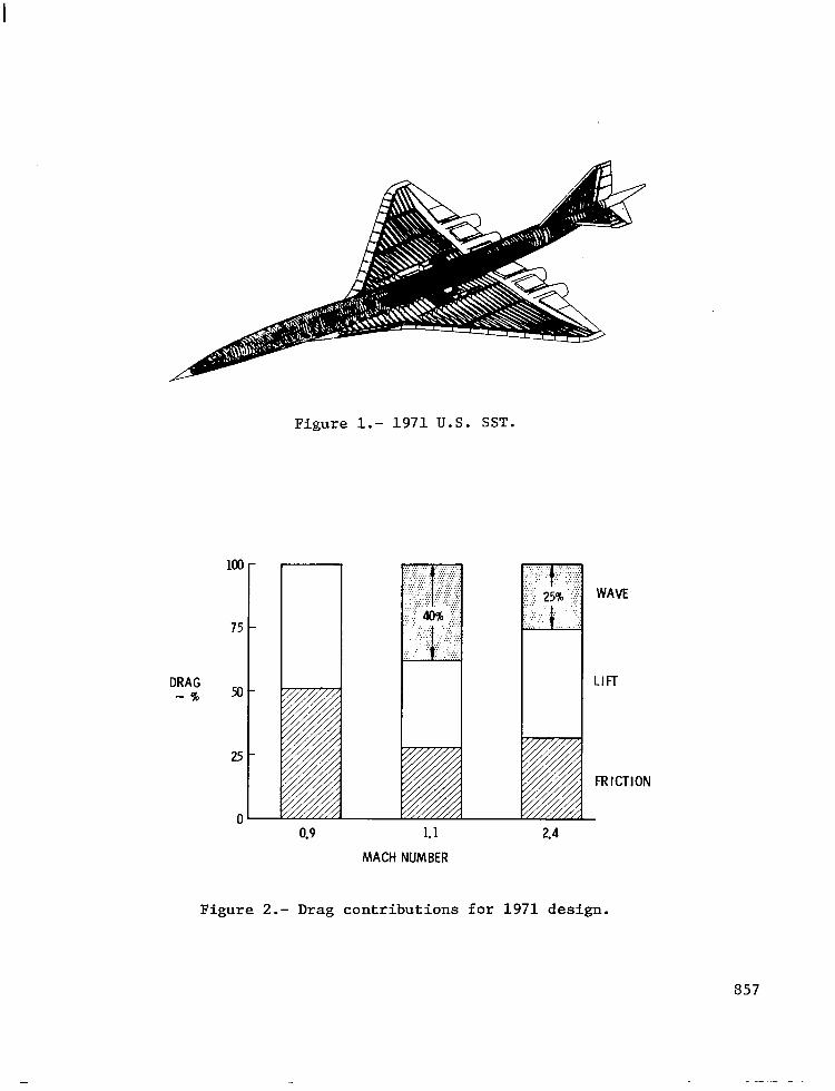
Figure l.- 1971 U.S. SST.
75
DRAG -90 5o
25
0
MACH NUMBER
WAVE
LIFT
FRICTION
Figure 2.- Drag contributions for 1971 design.
857
THINNER WING 1 IMPROVED DRAGIWEIGHTTRADE
HICKNESS I
.--L-- .----- , , . LARGER WING BOX . LARGER WING BOX =F =F I I . LESS ENGINE MOMENT . LESS ENGINE MOMENT _____ ------- _____ -------
. IMPROVED STRUaUR&E=&+-; . IMPROVED STRUaUR&E=&+-;
. LESS WEIGHT . LESS WEIGHT
t-
.I MODIFIED AIRFOIL
I 1
IEY: ----1971 d IMPROVED TRAILING EDGE EXlENSlON 1 c--l
SPAN --- ARGER STRAKE 1 (ALPHA LIMITER) ” T 1 pi.\ 1
REDUCED DRAG
Figure 3.- Wing improvements.
INCREASED DIAMETER
CROSS - LESS TRANSONIC DRAG - MORE PASSENGERS - BETlER MASS BALANCE
Figure 4.- Fuselage shape improvement.
858

I CONVENTIONAL I I
FRAMEISKIhISTRINGER
PASSENGER CABIN
WING RflY BLENDED WING-FUSELAGE
r TITANIUM SANDWICH, 5.0 cm
TITANIUM SANDWICH . DIFFUSION BONDED TITANIUM FRAMES
-3 WING BOX
SANDW IUi PRESSURE PANEL, 25 cm
Figure 5.- Fuselage cross-section comparison.
n TOTAL AREA
100 r 80
CROSS SECTION a AR& 40 PERCENT
LENGTH, PERCENT
Figure 6.- Effect of wing-body blending on cross-sectional area distribution for Mach number of 2.4.
859
ZD-
l5-
10 - TOTAL,
PERCENT 5-
o-
WING-FUSELAGE BLENDING / CONTRIBUTIOf’l
24 MACH NUMBER
Figure 7.- Recent lift/drag improvement.
Figure 8.- Geometric definition for blended configuration.
860 .
POTENT I AL lb% MANUFACTURING POTENT I AL lb% MANUFACTURING PRODUCTION COST SAWNGS PRODUCTION COST SAWNGS
Figure 9.- Figure 9.- Manufacturing complexity assessment. Manufacturing complexity assessment.
.-.-AA- ! ! ! METERS
Figure lO.- Blended wing-fuselage concept of the early 1960's.
861
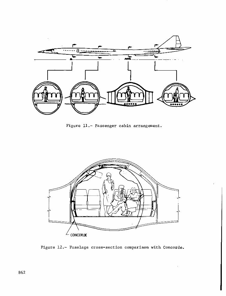
Figure ll.- Passenger cabin arrangement.
Figure 12.- Fuselage cross-section comparison with Concorde.
862

Figure 13.- Display of mock-up of blended cabin section.
Figure 14.- Closeup view of mock-up of blended cabin section.
863

PASSENGER CONTROLS . MULTIPLE OurSl# VIEWS . MULTIPLE VIDEO PROGRAMS . GENERAL INSTRUCTIONS
FLIGHT INFORMATION
\n c\ /ONBOARD CAMERA LOCATIONS
Figure 15.- Indirect outside viewing concept.
CONVENTIONAL DOORS- . LOADING . SERVICING . EVACUATION
Figure 16.- Overwing passenger evacuation.
864

Figure 17.- Emergency exit mock-up.
BENEFITS: ‘l!oi.
; ikGlNE . BEllER FUEL
w EFFICIENCY . IAti;RpC3;ED
RANGE
STRUCTURAL EFFICIENCYL/ . INNOVATIVE DESIGN . ADVANCED MFG. TECHNIQUES . STUCTURE ANALYSIS . WEIGHT, FLUflER
MANUFACTURING COST j/ . COMPLEXITY COMPARISON
PASSENGER EVACUATION L/ . DESIGN . FULL-SCALE MOCK-UP . TESTS
PASSENGER ACCEPTANCE L/ . INTERIOR/SYSTEM DESIGN . FULL-SCALE MOCK-UP . NO-WINDOW OPTIONS
GROUND SERVICING L/ 1
ENCOURAGING RESULTS
CONTINUE DEVELOPMENT
Figure 18.- Progress summary for blended configuration.
865

lIlllllllllIIIll I
Figure 19.- Artist conception of second-generation, fuel- efficient supersonic cruise airplane.
866