toward a practical, path-based framework for detecting and
TRANSCRIPT

Toward a Practical, Path-Based Framework for Detecting and
Diagnosing Software Faults
A Dissertation
Presented to
the Faculty of the School of Engineering and Applied Science
University of Virginia
In Partial Fulfillment
of the requirements for the Degree
Doctor of Philosophy
Computer Science
by
Wei Le
December 2010

c© Copyright November 2010
Wei Le
All rights reserved

Approvals
This dissertation is submitted in partial fulfillment of therequirements for the degree of
Doctor of Philosophy
Computer Science
Wei Le
Approved:
Mary Lou Soffa (Advisor)
Jack Davidson
Gregg Rothermel
David Evans (Chair)
Manuvir Das
Barry Horowitz
Accepted by the School of Engineering and Applied Science:
James H. Aylor (Dean)
December 2010

Abstract
One of the important challenges of developing software is the avoidance of software faults.
Since a fault occurs along an execution path, program path information is essential for both detect-
ing and diagnosing a fault. Manual inspection can identify apath where a fault occurs; however,
the approach does not scale. Dynamic techniques, such as testing, are also effective to find faulty
paths, but only in a sampled space.
This thesis develops a practical, path-based framework to statically detect and then diagnose
software faults. The techniques arepath-basedin that both detecting and reporting faults use path
information. An important contribution of the work is the development of a demand-driven analy-
sis that effectively addresses scalability challenges faced by traditional path-sensitive analyses. The
computed path information is shown to be valuable in automating diagnostic tasks and guiding soft-
ware testing to quickly exploit faults. A prototype tool, Marple, was developed to experimentally
evaluate the research.
Foundations of the thesis are the discoveries ofpath diversityandfault locality. Path diversity
says that if a fault is reported in terms of a program point, the assumption is that all the executions
across the same program point have the same property regarding the fault; however,safe, infeasible,
faulty with various severities and root causes, anddon’t-knowcan all traverse the same program
point. Given the path type, fault diagnosis can take action accordingly.Fault locality demonstrates
that instead of a whole program path, often only a path segment of 1–4 procedures, is relevant to a
fault. By only focusing on such path segments, fault detection and diagnosis can be more efficient.
To detect path types and path segments, a demand-driven analysis was developed, which
achieves interprocedural path-sensitivity and scales up to 570,000 lines of code. Evaluation of
iv

v
buffer overflow detection shows that the analysis is about 2 times faster than an exhaustive path-
sensitive tool. Generality of the technique is achieved viaa specification technique and an algorithm
that automatically generates path-based analyses for user-specified faults. The techniques are capa-
ble of handling both safety and liveness properties as well as both control and data-centric faults,
including buffer overflow, integer fault, null-pointer dereference and memory leak.
The usefulness of the path information is demonstrated for computingfault correlation, a causal
relationship between faults, and for guiding software testing to exploit faults. By grouping the
correlated faults, the number of static warnings needed fordiagnosis was reduced to about 53%. The
correlations also reveal that the propagation of integer faults can lead to not only buffer overflows
but also null-pointer dereferences, and resource leaks cancause infinite loops. Our path-guided
concolic testing successfully exploits 73% of statically identified faults. Compared to traditional
concolic testing, it is 25 times faster over a set of benchmarks on average to trigger the same
number of faults.

Acknowledgments
My deepest thanks first go to my advisor Dr. Mary Lou Soffa. It was her support and inspiration
that lead to my current accomplishment. Her invaluable advice and the interesting stories we had
shared during my Ph.D. will be remembered for the rest of my life.
My work was supported by Microsoft, who funded me through twointernships and the Mi-
crosoft Phoenix Academic Program, and also by Google, who provided me with the Anita Borg
Scholarship. The Microsoft Phoenix group, especially Dr. Andy Ayers, gave me tremendous ad-
vice and support for building my research prototype,Marple.
I would like to thank my committee members, including Drs. David Evans, Manuvir Das, Gregg
Rothermel, Jack Davidson and Barry Horowitz, who have provided many insightful comments
for my work and future directions. Thanks, too, to my colleagues both in the department and at
Microsoft for useful discussions about my research.
I am also grateful that our department provides a very supportive environment for female stu-
dents. Especially, I thank Dr. Anita Jones who was always available to me to provide advice and
encouragement.
Last but not least, my thanks go to my parents Debao Le and Linqiu Lu, and husband, Jeremy
Sheaffer. Without your support, I would not be what I am today.
vi

Contents
Acknowledgments vi
1 Introduction 1
1.1 Motivation . . . . . . . . . . . . . . . . . . . . . . . . . . . . . . . . . . . . . .. 1
1.2 The Problem . . . . . . . . . . . . . . . . . . . . . . . . . . . . . . . . . . . . . .2
1.3 Challenges of Developing a Path-Based Static Framework. . . . . . . . . . . . . 4
1.4 An Overview of the Research . . . . . . . . . . . . . . . . . . . . . . . . .. . . . 6
1.5 Thesis . . . . . . . . . . . . . . . . . . . . . . . . . . . . . . . . . . . . . . . . . 13
2 Background and Related Work 14
2.1 Faults . . . . . . . . . . . . . . . . . . . . . . . . . . . . . . . . . . . . . . . . . 14
2.2 Program Paths . . . . . . . . . . . . . . . . . . . . . . . . . . . . . . . . . . . .. 26
2.3 Implementation Support and Benchmarks . . . . . . . . . . . . . .. . . . . . . . 32
3 The Value of Paths for Detecting and Diagnosing Faults 38
3.1 Program Points v.s. Paths in Fault Detection and Diagnosis . . . . . . . . . . . . . 39
3.2 Selecting and Representing Path Information . . . . . . . . .. . . . . . . . . . . 48
3.3 Conclusions . . . . . . . . . . . . . . . . . . . . . . . . . . . . . . . . . . . . .. 53
4 Identifying Faulty Paths Using Demand-Driven Analysis 54
4.1 The Challenges . . . . . . . . . . . . . . . . . . . . . . . . . . . . . . . . . . .. 55
4.2 An Overview of the Analysis . . . . . . . . . . . . . . . . . . . . . . . . .. . . . 56
4.3 The Vulnerability Model and the Demand-Driven Algorithm . . . . . . . . . . . . 59
vii

Contents viii
4.4 Experimental Results . . . . . . . . . . . . . . . . . . . . . . . . . . . . .. . . . 66
4.5 Conclusions . . . . . . . . . . . . . . . . . . . . . . . . . . . . . . . . . . . . .. 73
5 Automatically Generating Path-Based Analysis 74
5.1 An Overview of the Framework . . . . . . . . . . . . . . . . . . . . . . . .. . . 75
5.2 Specification Language . . . . . . . . . . . . . . . . . . . . . . . . . . . .. . . . 76
5.3 Demand-Driven Template . . . . . . . . . . . . . . . . . . . . . . . . . . .. . . . 82
5.4 Generating Analysis . . . . . . . . . . . . . . . . . . . . . . . . . . . . . .. . . . 85
5.5 Experimental Evaluation . . . . . . . . . . . . . . . . . . . . . . . . . .. . . . . 89
5.6 Discussion . . . . . . . . . . . . . . . . . . . . . . . . . . . . . . . . . . . . . .. 95
5.7 Conclusions . . . . . . . . . . . . . . . . . . . . . . . . . . . . . . . . . . . . .. 96
6 Path-Based Fault Correlation 97
6.1 Motivation and Challenges . . . . . . . . . . . . . . . . . . . . . . . . .. . . . . 98
6.2 Defining Fault Correlation . . . . . . . . . . . . . . . . . . . . . . . . .. . . . . 100
6.3 Computing Fault Correlation . . . . . . . . . . . . . . . . . . . . . . .. . . . . . 106
6.4 Correlation Graphs . . . . . . . . . . . . . . . . . . . . . . . . . . . . . . .. . . 113
6.5 Experimental Results . . . . . . . . . . . . . . . . . . . . . . . . . . . . .. . . . 115
6.6 Conclusions . . . . . . . . . . . . . . . . . . . . . . . . . . . . . . . . . . . . .. 120
7 Path-Guided Concolic Testing 121
7.1 An Example . . . . . . . . . . . . . . . . . . . . . . . . . . . . . . . . . . . . . . 122
7.2 An Overview of MAGIC . . . . . . . . . . . . . . . . . . . . . . . . . . . . . . .124
7.3 Obtaining Static Path Information . . . . . . . . . . . . . . . . . .. . . . . . . . 127
7.4 Dynamic Testing . . . . . . . . . . . . . . . . . . . . . . . . . . . . . . . . . .. 130
7.5 Implementation and Evaluation . . . . . . . . . . . . . . . . . . . . .. . . . . . . 137
7.6 Conclusions . . . . . . . . . . . . . . . . . . . . . . . . . . . . . . . . . . . . .. 140
8 Conclusions and Future Work 141
8.1 Contributions and Impact . . . . . . . . . . . . . . . . . . . . . . . . . .. . . . . 141

Contents ix
8.2 Future Work . . . . . . . . . . . . . . . . . . . . . . . . . . . . . . . . . . . . . .143
Bibliography 145

List of Figures
1.1 Research Process: Five Projects for the Thesis Research. . . . . . . . . . . . . . 7
1.2 Three Types of Path-Sensitive Analysis . . . . . . . . . . . . . .. . . . . . . . . 8
1.3 Goals, Solutions and Results . . . . . . . . . . . . . . . . . . . . . . .. . . . . . 9
2.1 A Stack Buffer Overflow and Its Exploit . . . . . . . . . . . . . . . .. . . . . . . 15
2.2 An Example of Null-Pointer Dereference . . . . . . . . . . . . . .. . . . . . . . 17
2.3 Static Analysis for Fault Detection and Diagnosis . . . . .. . . . . . . . . . . . . 23
2.4 Path-Sensitive Analysis: the State-of-the-Art . . . . . .. . . . . . . . . . . . . . 29
2.5 the Interactions of Phoenix, Disolver and Marple . . . . . .. . . . . . . . . . . . 33
3.1 An Example from Sendmail-8.7.5 . . . . . . . . . . . . . . . . . . . . .. . . . . 40
3.2 Different Paths Cross a Buffer Overflow Statement . . . . . .. . . . . . . . . . . 41
3.3 Path-Sensitive Root Causes . . . . . . . . . . . . . . . . . . . . . . . .. . . . . . 42
3.4 Summary of Comparison . . . . . . . . . . . . . . . . . . . . . . . . . . . . .. . 47
3.5 Identifying Useful Path Information: the Six Elements .. . . . . . . . . . . . . . 50
3.6 Using Path Graph to Represent a Set of Paths: dash lines are shared edges for
different paths . . . . . . . . . . . . . . . . . . . . . . . . . . . . . . . . . . . . 51
4.1 Four Components . . . . . . . . . . . . . . . . . . . . . . . . . . . . . . . . . .. 56
4.2 Detecting Different Types of Faults . . . . . . . . . . . . . . . . .. . . . . . . . 58
4.3 Interactions of the Vulnerability Model and the Analyzer . . . . . . . . . . . . . . 62
4.4 An Overflow in bc-1.06, main.c. . . . . . . . . . . . . . . . . . . . . . .. . . . . 69
4.5 Overflows in MechCommander2, Ablscan.cpp. . . . . . . . . . . .. . . . . . . . 70
x

List of Figures xi
4.6 Comparison of Marple with other five static detectors on ROC plot . . . . . . . . . 71
5.1 The Framework . . . . . . . . . . . . . . . . . . . . . . . . . . . . . . . . . . . .75
5.2 The Grammar of Specification Language . . . . . . . . . . . . . . . .. . . . . . 78
5.3 Partial Buffer Overflow Specification . . . . . . . . . . . . . . . .. . . . . . . . 80
5.4 Partial Memory Leak Specification . . . . . . . . . . . . . . . . . . .. . . . . . 81
5.5 Parsing Specification . . . . . . . . . . . . . . . . . . . . . . . . . . . . .. . . . 88
5.6 Generating Code from Syntax Tree . . . . . . . . . . . . . . . . . . . .. . . . . 89
6.1 Fault Correlation in ffmpeg-0.4.8 . . . . . . . . . . . . . . . . . .. . . . . . . . 99
6.2 Defining Fault Correlation: correlated faults are marked with ×, error state is in-
cluded in [ ], and corrupted data are underlined . . . . . . . . . . .. . . . . . . . 102
6.3 Correlation of Resource Leak and Infinite Loop in acpid . .. . . . . . . . . . . . 104
6.4 Correlations of Multiple Buffer Overflows in polymorph .. . . . . . . . . . . . . 105
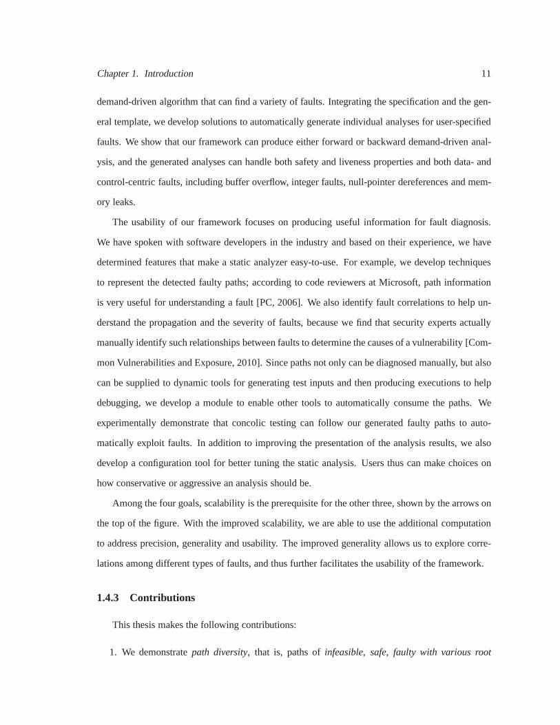
6.5 Fault Detection and Fault Correlation . . . . . . . . . . . . . . .. . . . . . . . . 107
6.6 Correlation via Direct Impact . . . . . . . . . . . . . . . . . . . . . .. . . . . . . 109
6.7 Correlation via Feasibility Change . . . . . . . . . . . . . . . . .. . . . . . . . . 111
6.8 Correlation Graphs for Examples . . . . . . . . . . . . . . . . . . . .. . . . . . . 114
7.1 Comparing Concolic Testing and MAGIC Using an Example . .. . . . . . . . . . 124
7.2 The Components of MAGIC . . . . . . . . . . . . . . . . . . . . . . . . . . . .. 125
7.3 The Workflow of MAGIC . . . . . . . . . . . . . . . . . . . . . . . . . . . . . . .126
7.4 A Path Graph for Two Suspicious Path Segments . . . . . . . . . .. . . . . . . . 129
7.5 Multiple Strings in a Buffer . . . . . . . . . . . . . . . . . . . . . . . .. . . . . . 132
7.6 Buffer Overflow Condition . . . . . . . . . . . . . . . . . . . . . . . . . .. . . . 133

List of Tables
2.1 Path-Sensitive Dataflow Analysis for Identifying Faults . . . . . . . . . . . . . . . 30
3.1 Different Types of Paths can Cross a Buffer Overflow Statement . . . . . . . . . . 46
3.2 Comparison of Splint and Marple . . . . . . . . . . . . . . . . . . . . .. . . . . . 46
3.3 The Length of the Path Segments Computed for a Given Buffer Overflow . . . . . 52
4.1 Partial Buffer Overflow Vulnerability Model . . . . . . . . . .. . . . . . . . . . . 59
4.2 Detection Results from Marple . . . . . . . . . . . . . . . . . . . . . .. . . . . . 67
4.3 Benefit of Demand-Driven Analysis . . . . . . . . . . . . . . . . . . .. . . . . . 72
5.1 Detecting Multiple Types of Faults . . . . . . . . . . . . . . . . . .. . . . . . . . 91
5.2 Scalability . . . . . . . . . . . . . . . . . . . . . . . . . . . . . . . . . . . . .. . 92
5.3 Comparison of Memory Leak . . . . . . . . . . . . . . . . . . . . . . . . . .. . 94
6.1 Error State of Common Faults . . . . . . . . . . . . . . . . . . . . . . . .. . . . 101
6.2 Types of Correlated Faults Discovered in CVE . . . . . . . . . .. . . . . . . . . . 106
6.3 Automatic Identification of Fault Correlations . . . . . . .. . . . . . . . . . . . . 117
6.4 Characteristics of Fault Correlations . . . . . . . . . . . . . .. . . . . . . . . . . 118
6.5 Correlation Graphs and their Analysis Costs . . . . . . . . . .. . . . . . . . . . . 119
7.1 Modeling Buffer Overflow Conditions . . . . . . . . . . . . . . . . .. . . . . . . 132
7.2 Symbolic Semantics of String and Pointer Operations . . .. . . . . . . . . . . . . 134
7.3 Comparison of Testing Time and Fault Detection Capability . . . . . . . . . . . . 138
7.4 Comparison of Test Input Generation Costs . . . . . . . . . . . .. . . . . . . . . 139
xii

Chapter 1
Introduction
1.1 Motivation
Software continues to play a critical role in all aspects of our lives, from personal safety to public
health, from phones and appliances used in daily life to vital infrastructures of air traffic control,
medical devices and power generation and distribution systems. Due to its ubiquity and importance,
software needs to be reliable and robust. In fact, 40% of system failures are attributable to software
faults [Marcus and Stern, 2000], and software faults are thedirect cause of patient deaths in the
Therac-25 radiation therapy [Leveson and Turner, 1993], the Ariane rocket crash [Inquiry Board,
1996], and the Mars Climate Orbiter explosion [Investigation Board, 1999].
Building reliable and robust software is challenging. A primary reason is that software is com-
plex: 1) the code size can be incredibly large, consisting ofdiverse components; 2) newer and
different programming paradigms are used, for example, concurrency and parallelization are be-
coming more and more important for developing modern software; 3) newly developed code needs
to be compatible with legacy code; and 4) software is required to run on a variety of hardware and
system environments. Yet software is developed manually, and human beings make mistakes. As
a result, human understanding of software does not scale to the rapid growth of software size and
complexity, and faults are unavoidably introduced in software during both design and coding. A
study commissioned by the Department of Commerce in 2001 shows that for a typical software
development project, fully 80% of software development dollars are spent in identifying and cor-
1

Chapter 1. Introduction 2
recting software faults; however, despite the effort, software faults cost the U.S. Economy $59.5
billion annually, about 0.6 percent of the gross domestic product (GDP) [NIST, 2002]. Effective
fault management tools are desirable to help improve the productivity of software assurance and
further remove faults.
1.2 The Problem
Since a fault is produced on an execution path, to detect faults, ideally we should examine
each program path and determine if a fault can occur. By Rice’s theorem, determining a non-
trivial property for a program is undecidable. To achieve a reasonable speed and ensure software
still can be shipped on time, we either have to sample a limited number of executions, which
potentially will miss an unpredictable number of faults, orwe need to reduce the state space by
merging program paths. In fact, in many of the tools in the state-of-the-art, faults are detected using
conservatively merged information from all paths and reported at a particular program point, which
causes imprecision and requires much manual effort to confirm and diagnose the detection results.
Our insight is that program paths are important for both precisely detecting and efficiently
diagnosing faults. If a fault is reported in terms of a program point as typical, all executions that
traverse the program point are considered as having the sameproperty regarding the fault. Actually,
both safe and faulty paths can traverse the same program point. Even for faulty paths, the severity
and root causes associated with the fault can be different. If the paths where a fault can occur are
given, manual or automatic diagnosis can follow the guidance and take action accordingly based on
the type of paths.
To identify a path where a fault occurs, there are three general approaches: manual inspection,
dynamic detection and static analysis. The main disadvantage of manual inspection is efficiency.
Research shows that on average the estimated speed of code inspection is only 120 lines per person
hour [Hatton, 2008]. Code inspection might be useful to review high level design decisions such as
software architecture, but it is not practical to manually examine every path of a program for cor-
rectness. In practice, manual inspection is often used withstatic tools to confirm reported warnings

Chapter 1. Introduction 3
or to help diagnose complex faults triggered in the field.
Dynamic detection executes a program with inputs, and determines the deviation (if any) of the
program behavior via the observed symptoms. One advantage of a dynamic tool is soundness, i.e.,
the fault triggered in detection demonstrates the symptomsthat would later manifest in the field.
Since execution paths can be obtained, software developersare able to understand the transition of
the program states and thus the development of a fault. One drawback of a dynamic tool is that it
can only show the presence but not the absence of a bug; that is, often only a limited number of
paths and restricted input space can be examined. A dynamic tool would be applied at the late stage
of software lifecycle, when program executables and test inputs are available. The bugs found at
this stage are considered ten times more expensive to fix thanthe ones found earlier, e.g., during
coding [Kaner et al., 2001].
Another technique is static analysis. Static analysis scans program source code for predefined
bug patterns, and reports locations in the code where a faultpotentially occurs. Static analysis has
been integrated in software development in many software companies. According to data in 2005, a
Microsoft program analysis group filed more than 7000 bug reports in one month using their static
tools [Das, 2005]. Static analysis requires only program source code and thus can find faults early,
when fixing a bug is relatively cheap. In fact, at Microsoft, static tools are deployed at desktops, and
code is only allowed to be checked in when it passes the inspection of these tools. Static analysis
also outperforms dynamic detection in its full coverage of paths; therefore it potentially finds faults
on the paths that a dynamic tool cannot reach. Many dynamic tools rely on the guidance of static
information for improved coverage [Sen et al., 2005,Godefroid et al., 2005]. Despite its advantages
and initial successes, existent static techniques are limited in their capability of determining and
explaining faults, as well as in the high cost of developing,maintaining and using the tools.
This thesis presents a practical,path-basedframework for statically detecting and then diagnos-
ing faults. A novelty of this work is that our technique ispath-basedin that we not only consider
path information in determining a fault, but also compute various path properties for diagnosing a
fault. For example, we discovered that most of the time, onlya segment of a path, instead of the
whole program path, is responsible for producing a fault, and we thus can provide more focus for

Chapter 1. Introduction 4
fault diagnosis. We also show that paths of different root causes and severity can be distinguished,
based on which, we can better schedule the diagnostic tasks.In addition, we find that along fault
propagation, different types of faults can interact and then lead to visible consequences; identifying
fault relationships and impacts can help group and prioritize faults.
An important contribution of the work is that we make computation of the path information
practical; that is, the scalability and precision achieved on the framework are applicable for real-
world deployed software for a variety of faults. In order to make the expensive path-sensitive
feasible, we reduce the state space based onfault locality; that is, we detect and report the sequence
of, but not the whole, execution along a path for a fault, and only perform an expensive path-
sensitive analysis on the portion of the program that is relevant to a fault. Using the automatically
computed path information, we identify the relationships of faults along the propagation, which
was previously done manually, and guide the dynamic testingto automatically exploit the faults.
1.3 Challenges of Developing a Path-Based Static Framework
The challenges of developing a path-based static frameworkare 1) to achievescalability and
precisionof the static analysis required by fault detection, 2) to addressgeneralityof the techniques
so that the analysis is applicable for a variety of faults, and 3) to ensureusability of both the tool
and the results reported by the tool.
Static analysis is potentially imprecise for two reasons. First, in a whole program analysis,
it is infeasible to examine all program paths for faults. Instead, approximations, e.g., via merg-
ing or abstracting of program paths, have to be applied to reduce the state space. When multiple
program states are merged at a program point to derive a summary, imprecision can occur, as re-
ported by path-insensitive analysis [Hallem et al., 2002,Evans, 1996]. Abstraction also can lead to
imprecision. For example, in software model checking, programs are mapped to software models
such as pushdown automa; however, the traces from the model are not always the paths from the
program [Chen and Wagner, 2002].
Another reason for imprecision is that static analysis onlyconsiders the program source to

Chapter 1. Introduction 5
determine the faults. However, program inputs and the external environment are also important
for reasoning about the potential program behaviors. Without properly modeling such information,
static analysis can make overly conservative or aggressiveassumptions. A conservative analysis can
lead tofalse positives, i.e., reporting faults which are actually not faults. Contrarily, an aggressive
analysis can make “wrong guesses” and lead tofalse negatives; that is, static analysis would miss
faults.
Besides precision, scalability is a related challenge thatcan prevent a static tool from being use-
ful. A scalable static analysis should be able to handle reasonably size software, and importantly,
the additional cost of coping with a given increase in code size should be manageable. For exam-
ple, a naive exhaustive path-sensitive analysis is not scalable, because the analysis cost increases in
terms of the growth of path numbers in the program, which can be exponential to the size of the pro-
gram. To measure scalability, both time and space, e.g., memory or disk storage, used by analysis,
need to be considered. Existing techniques for scalabilityare not ideal in that they either sacrifice
the analysis precision [Bush et al., 2000], impact the general applicability [Das et al., 2002,Xie and
Aiken, 2007], or require a considerable amount of manual effort to use [Hackett et al., 2006].
Another important goal for designing static analyzers is toreduce the amount of manual effort
needed to construct, maintain and use a tool. The goal requires both generality and usability. A
general static tool should handle a variety of faults, and especially, it should be able to respond to a
new type of fault without requiring the reconstruction of the whole analysis. Achieving generality
is challenging. First, we need to determine whether a general algorithm is feasible for identifying
a variety of faults; if so, we need a way to specify different faults. The specification for fault
patterns should be complete; that is, the specification should include all scenarios in which a fault is
potentially manifested in the source code. We also require the fault patterns to be distinctive, using
which we can distinguish malicious errors from benign ones.The second challenge to achieve
generality is that the precision and scalability tailored for one specific type of fault can be no longer
usable. Due to the challenges, generality in the state-of-the-art is mainly restricted to a subcategory
of faults, such as typestate [Strom and Yemini, 1986] violations. As a result, repeated efforts have
to be expended to build and maintain individual fault detectors.

Chapter 1. Introduction 6
Usability refers to how easily a static tool can be used, and more specifically, how easily a user
can specify faults, configure the tool, or use the bug reportsto correct the faults. It should be noted
that the focus here is not formal user studies, but whether a static tool considers empirical user
experience and integrates features that help reduce manualeffort to use the tool. For example, some
tools require the use of annotations to help analysis, whileboth writing and verifying annotations
require much manual effort. Another determinant factor of usability is the quality of bug reports.
Many static tools only report a program point where a fault potentially occurs. To understand how a
fault is developed along executions, code inspectors have to manually explore the paths that traverse
the reported program points, which is time consuming and error prone.
The above four challenges are not independent factors, as the techniques used to address one
challenge might compromise the other. For example, applying heuristics for scalability impacts
precision. Introducing annotations for precision sacrifices usability. The ultimate reason that these
challenges exist is that static analysis is undecidable. Wethus should develop algorithms that can
use the available computation resources for nearly optimalsolutions, which means 1) we should
avoid computing information that is not needed; and 2) we should avoid repeated computation and
instead, reuse intermediate results if possible. In our research, we use these two principles and
develop scalable algorithms that handle the requirements of precision, generality and usability.
1.4 An Overview of the Research
This section summarizes the thesis research from three different angles. First, we introduce
the development of the five projects in our research process.Second, we list the set of solutions
found in our research that addressed the targeted challenges specified in Section 1.3. Finally, we
summarize our contributions.
1.4.1 A Description of Five Research Projects
This research is developed in three stages, shown as Figure 1.1. In themotivationstage, our
goals are to identify the value of paths for detecting and diagnosing faults, and meanwhile to deter-

Chapter 1. Introduction 7
Figure 1.1: Research Process: Five Projects for the Thesis Research
mine path information that is potentially useful in fault diagnosis. In this project, we proposed and
experimentally validated two important hypotheses: 1) paths that contain different fault properties
(e.g., the presence, type, severity or root cause of a fault)can traverse the same program point, and
thus manual and automatic diagnosis can take correspondingactions based on the types of paths;
and 2) faults manifest locality, and it is the path segment along a program path that contributes to
the cause of a fault. We therefore can use the information identified on path segments to diagnose
faults.
In the frameworkstage, we develop the techniques to automatically compute path information
regarding faults. The two important contributions include: 1) we demonstrate that demand-driven
analysis is feasible and scalable for detecting faulty paths; and 2) we develop a fault model and
a specification technique that enable the applications of demand-driven analysis to both data- and
control-centric faults as well as faults regarding both liveness and safety properties.
In Figure 1.2, we compare demand-driven analysis with othertwo categories of techniques
previously applied in path-sensitive fault detection. In the figure, each rectangle represents the state
space that a static analysis needs to explore: the height of the rectangle indicates the number of
paths in a program, and the width displays the length of a path. Each strip in a rectangle represents
a path. In the first approach, static analysis exhaustively explores all program paths based on the

Chapter 1. Introduction 8
structure of the program. More likely, resources would be exhausted before all the faults can be
found. In the second approach, static analysis randomly searches paths for faults. Research shows
that this approach can find faults more quickly than the first approach [Dwyer et al., 2007]; however,
faults also can be missed.
The demand-driven analysis improves the scalability by only collecting the information needed
for a fault. Applyingdemand-drivenanalysis to detect faults, we first perform a low-cost source
code scan to identify program points where a fault is potentially observed. We then conduct a path-
sensitive analysis only on the code that is relevant to the faults, i.e. the path segments between the
program entry and the identified program points. Compared toan exhaustive analysis, demand-
driven analysis potentially explores a fewer number of program paths, because only the paths that
traverse the program points of interest need to be examined.In the figure, we represent the reduction
of the path number using the shortened breadth in the rightmost rectangle. In addition, our path-
sensitive analysis starts where a fault potentially occursand terminates as soon as the decision about
the fault is made, when only a segment of paths may be explored. Therefore, the length of a path
we analyze is also reduced, shown as the shortened height foreach strip in the rightmost rectangle.
Figure 1.2: Three Types of Path-Sensitive Analysis
In the third stage of our research, shown in Figure 1.1, we study the use of paths for fault
diagnosis. In one project, we find that a casual relationshipcan exist between faults, which we
call fault correlation, such as “an integer overflow can lead to a buffer overflow”. Inpractice, code

Chapter 1. Introduction 9
inspectors manually determine such relationships betweenfaults for understanding the impact of a
fault. Using the faulty paths computed, we develop an algorithm to automatically determine fault
correlations. In another project, we find that path information is useful to reduce state space of path-
based test input generation. We develop a path-guided concolic testing technique that successfully
exploits statically identified faults.
We implement our techniques in a prototype tool, calledMarple, which we use to experimen-
tally evaluate the effectiveness of the techniques.
1.4.2 A Summary of Solutions Provided by the Framework
Figure 1.3: Goals, Solutions and Results
The thesis addresses the four challenges of the static faultdetection discussed in Section 1.3.
In Figure 1.3, we present a summary of our solutions with respect to these challenges. The key
that leads to those solutions is the application of a demand-driven, path-based analysis. The figure
is divided into three parts. At the top of the figure, we list the four challenges we aim to address.

Chapter 1. Introduction 10
In the middle of the figure, we present a set of techniques developed to accomplish the goals. At
the bottom of the figure, we display results that demonstratethe effectiveness of our techniques in
conquering the targeted goals.
In the figure, underPrecision, we summarize our techniques applied to improve the precision of
the analysis. We have pointed out that the two major imprecision sources are: the approximation in-
troduced to reduce the state space and the heuristics applied to model factors beyond program source
(see discussion in Section 1.3). We address the first challenge using an interprocedual path-sensitive
analysis. For the second source of imprecision, we introducedon’t-knowtags in an analysis to mark
positions where imprecision can occur. The idea of don’t-know is that we allow heuristics to be in-
troduced to determine faults, but we are aware what and whereheuristics are applied. Based on the
corresponding results, we can thus decide whether or not to continue applying them. In the figure,
we use arrows to connect the boxes of don’t-know and externalinformation, indicating that the two
techniques are integrated together to handle potential imprecision. By applying the above set of
techniques, our experiments report low false positive and false negative rates for analyzing a set of
real-world programs.
For scalability, we develop a demand-driven analysis and a set of optimizations based on the
analysis. In addition, we integrate two design principles,including terminate earlyandseparate
concerns. Terminate earlymeans that the analysis always terminates when the status ofthe paths
is determined, either as safe, containing faults or don’t-know; the analysis would not use arbitrary
heuristics and allocate computation resources for producing unpredictably imprecise results.Sep-
arate concernsmeans we separate complex properties of a path into several individual properties,
each of which can be efficiently resolved on the framework. Wethen compose the properties for the
paths that we aim to compute. For example, in our analysis, determining path feasibility and detect-
ing faults are performed in two separate passes of an analysis, so that the infeasible paths identified
can be reused in determining different types of faults. The effectiveness of the above techniques is
demonstrated in our experiments, where our analysis terminates for large software such asputty
andapache with reasonable time and space overhead.
Generality is achieved via a fault model and a specification technique. We design a general
Chapter 1. Introduction 11
demand-driven algorithm that can find a variety of faults. Integrating the specification and the gen-
eral template, we develop solutions to automatically generate individual analyses for user-specified
faults. We show that our framework can produce either forward or backward demand-driven anal-
ysis, and the generated analyses can handle both safety and liveness properties and both data- and
control-centric faults, including buffer overflow, integer faults, null-pointer dereferences and mem-
ory leaks.
The usability of our framework focuses on producing useful information for fault diagnosis.
We have spoken with software developers in the industry and based on their experience, we have
determined features that make a static analyzer easy-to-use. For example, we develop techniques
to represent the detected faulty paths; according to code reviewers at Microsoft, path information
is very useful for understanding a fault [PC, 2006]. We also identify fault correlations to help un-
derstand the propagation and the severity of faults, because we find that security experts actually
manually identify such relationships between faults to determine the causes of a vulnerability [Com-
mon Vulnerabilities and Exposure, 2010]. Since paths not only can be diagnosed manually, but also
can be supplied to dynamic tools for generating test inputs and then producing executions to help
debugging, we develop a module to enable other tools to automatically consume the paths. We
experimentally demonstrate that concolic testing can follow our generated faulty paths to auto-
matically exploit faults. In addition to improving the presentation of the analysis results, we also
develop a configuration tool for better tuning the static analysis. Users thus can make choices on
how conservative or aggressive an analysis should be.
Among the four goals, scalability is the prerequisite for the other three, shown by the arrows on
the top of the figure. With the improved scalability, we are able to use the additional computation
to address precision, generality and usability. The improved generality allows us to explore corre-
lations among different types of faults, and thus further facilitates the usability of the framework.
1.4.3 Contributions
This thesis makes the following contributions:
1. We demonstratepath diversity, that is, paths ofinfeasible, safe, faulty with various root

Chapter 1. Introduction 12
causes and severitiesanddon’t-knowcan traverse the same program point. The path classifi-
cation can guide the fault detection to achieve better precision, and help prioritize and explain
detection results for fault diagnosis [Le and Soffa, 2007,Le and Soffa, 2008].
2. We demonstrate that faults manifest locality, i.e., often a fault is relevant to only several
procedures along a path, instead of the whole program path. Therefore, by focusing on such
path segments, both fault detection and diagnosis can achieve better performance [Le and
Soffa, 2007,Le and Soffa, 2008].
3. We develop a demand-driven analysis that statically identifies user-specified faults. In our
feasibility study, we applied the analysis to buffer overflow detection and demonstrated its
scalability. The work validates the hypothesis that the demand-driven analysis only visits the
code that is relevant to the faults and terminates only when asmall portion of the code is
analyzed [Le and Soffa, 2008].
4. We develop a fault model and a specification language that can specify both control- and
data-centric faults as well as both liveness and safety properties [Le and Soffa, 2011].
5. We design an algorithm to automatically generate individual analyses from specifications
and a general demand-driven template. The generated analysis can handle one or several
types of specified faults. We experimentally show that the generality does not compromise
scalability, and the analysis is able to scale at least for identifying buffer overflow, integer
faults, null-pointer dereferences and memory leaks [Le andSoffa, 2011].
6. We define fault correlations and demonstrate their valuesfor understanding faults. We also
develop algorithms to automatically compute paths along which two faults are correlated [Le
and Soffa, 2010].
7. We develop techniques to integrate statically computed path information with the path-based
test input generation. In our evaluation, we show that usingpath-guided concolic testing, we
can automatically generate test inputs that exploit our statically identified faults, and with the

Chapter 1. Introduction 13
guidance of the path information, concolic testing is able to more quickly find faults [Cui
et al., 2011].
8. The framework is implemented in a research prototype Marple. It takes the program source
and user supplied specifications, and reports the paths withdifferent fault properties for spec-
ified faults. The tool is configurable and applicable for analyzing Windows compilable soft-
ware.
Contributions 1 and 2 are presented in Chapter 3 and contribution 3 in Chapter 4. As the effort
of making the framework more generally applied, Chapter 5 includes contributions 4 and 5. The
applications of path information are summarized in contributions 6 and 7, which are shown in
Chapters 6 and 7 respectively.
1.5 Thesis
The thesis presents scalable, general path-sensitive algorithms for detecting faults and deter-
mining fault correlations. It demonstrates that static path information regarding faults can be made:
• valuable for both fault detection and diagnosis;
• practical in that paths can be identified with reasonable precision andscalability; and
• broad to address paths of a variety of faults, and paths of multiplejoint properties.

Chapter 2
Background and Related Work
Two key concepts of this thesis arefaults and program paths. We organize the background
chapter based on the two concepts. Underfaults, we define faults and common fault types; we then
introduce techniques and terminologies related to detecting and diagnosing faults. Similarly, under
program paths, we provide definitions related to paths; we then present theexistent work on com-
puting and using program paths. At the end of the chapter, we provide information about our imple-
mentation and experimentation. In particular, we explain the use of the Microsoft Phoenix [Phoenix,
2004] and Disolver [Hamadi, 2002] in the development of the tool Marple and also our choices of
benchmarks for experiments.
2.1 Faults
Definition 2.1: a programfault is an abnormal condition caused by the violation of a required
property at a program point. Thepropertycan be specified as a set of constraints to which a program
has to conform.
Fault is a dynamic concept, i.e., a fault occurs when a program runs. Research shows that certain
types of malfunction in dynamic behavior can be predicted statically using patterns of program
source code [Evans, 1996, Bush et al., 2000, Das et al., 2002,Xie et al., 2003, Xie and Aiken,
2007, FindBugs, 2005, Le and Soffa, 2008]. The goal of staticfault detection is to apply static
analysis on program source to determine the potential occurrence of a fault.
14

Chapter 2. Background and Related Work 15
2.1.1 Common Fault Types
We focus on the following four types of faults,buffer out-of-bounds, integer fault, null-pointer
dereferenceand resource leak. They are chosen because 1) these types of faults are commonly
seen in software; 2) identifying them is important for software reliability and security, as they can
cause programs to crash, hang, slowdown, be exploited or produce incorrect results, 3) they are not
simple syntactic faults that can be found during compilation, and instead, only advanced semantic
analyzers are able to statically identify them, and 4) the four types are representative for both data
and control centric faults, and include both liveness and safety properties.
Definition 2.2: If a write or read of bufferv accesses the memory outside the boundary ofv,
a bufferout-of-boundsoccurs. If the access is beyond the buffer, e.g., at the address larger than
[Address(v)+size(v)], the fault is abuffer overflow; otherwise, if the out-of-bounds access is before
the buffer, e.g., at the address less than[Address(v)], it is abuffer underflow. A buffer is a chunk of
memory that storesn (n > 0) number of elements of the same type. In program code, a buffercan
be identified using a source variablev; any element in the buffer can be accessed usingv[i] (i is the
index of the buffer).
Buffer out-of-bounds can occur in the stack, heap or data section, and in all of the three cases,
buffer overflow/underflow are exploitable [CERT, 2010]. In Figure 2.1, we show a stack buffer
overflow and the exploit targeted to this buffer overflow.
(a) Code with a Buffer Overflow (b) Exploiting the Buffer Overflow
Figure 2.1: A Stack Buffer Overflow and Its Exploit

Chapter 2. Background and Related Work 16
In Figure 2.1(a), there is a buffer overflow vulnerability atnode 3 on a stack buffera. In
Figure 2.1(b), we show that an inputa[100]=”111...1” (with more than a 100 ”1”) taken at node 3
overflows buffera, and as a result,auth located adjacent to the buffer on the stack is overwritten
(assuming the memory layout shown as Figure 2.1). Due to the buffer overflow, the valueauth
is controllable by external users, and therefore an unauthorized access can occur at node 5. This
buffer overflow is a simplified version of an exploited SSHD vulnerability [Chen et al., 2005].
Next, we introduce three types of integer faults:truncation error, overflow/underflow, and
signedness error.
Definition 2.3: An integer truncation erroroccurs when 1) an integer with a largerwidth is
assigned to an integer with a smaller width and 2) the destination integer cannot accommodate the
value. Integer widthmeasures the number of bytes used in the machine to representa specific type
of an integer.
For example, in C and C++, there exist integer types ofchar, short, int, andlong; their
corresponding sizes are 1, 2, 4, and 8 bytes. When an integer,e.g., 1024, with thelong type is
assigned to the integer ofchar type, a truncation error occurs. Instead of 1024, we would get 0
after the assignment.
Definition 2.4: An integer overflow/underflowoccurs when an integer arithmetic returns a value
that the destination integer cannot accommodate: if the value is larger than the maximum value the
destination integer can store, aninteger overflowoccurs; otherwise, if the value is smaller than the
minimum value the destination integer can store, aninteger underflowoccurs.
For some languages such as C and C++, the values an integer canstore are dependent not only
on the integer type, but also itssignedness. An unsignedinteger is always non-negative, and all
of its bits are interpreted as values. Asignedinteger can represent negative values, and often, its
highest bit indicates whether the integer is positive or negative.
Definition 2.5: An integer signedness erroroccurs when a signed integer is converted to un-
signed (or when an unsigned integer is converted to signed),and its value cannot be represented by
the destination integer.
The three types of integer faults listed in Definitions 2.3–2.5 share one commonality: they oc-

Chapter 2. Background and Related Work 17
cur when a value, either from some integer or integer arithmetic, is assigned to an integer, and
the destination integer cannot accommodate the value. The outcomes of the assignment in pres-
ence of integer faults are either defined in the language standard or implementation dependent. As
the results are often not expected, integer faults can lead to incorrect results, program crashes or
exploits [SecurityTeam, 2010,Common Vulnerabilities andExposure, 2010].
The next category of faults is related to the pointer usage.
Definition 2.6: A null-pointer dereferenceoccurs when the program attempts to dereference a
pointer whose value is NULL.
Null-pointer dereference can cause the program to crash or even be exploitable. Figure 2.2
shows a proof-of-concept example on how a null-pointer dereference is exploited. In Figure 2.2(a),
the pointer dereferencea->i at node 3 encounters a null-pointera. As a result, the program would
access the memory at addressx ( x is the offset of variable i in struct A), which most of the
time is not a legitimate user memory space, and thus the program would crash. Sometimes, an
authorization token is by chance located at addressx, as shown in Figure 2.2(b), in which case the
assignment at node 3 can change the value ofauthand allow a non-authorized access at node 5.
(a) a NULL-Pointer Dereference (b) Exploiting NULL-Pointer Dereference
Figure 2.2: An Example of Null-Pointer Dereference
Pointer related faults also include the dereferences of uninitialized, untrusted, or already freed
pointers. They are all similar to null-pointer deferences in that the fault occurs when the pointer

Chapter 2. Background and Related Work 18
dereference is not performed in a proper context.
Finally, the last category of fault is about the usage of resource in software systems.
Definition 2.7: A resource leakoccurs if some allocated resource is never released. One ex-
ample ismemory leak. A memory leak occurs when a chunk of allocated memory is never freed.
Memory leaks can slow down or even crash a program. Other resource leak examples include
“a file is never closed after open”, which can cause a program to crash or leak security sensitive
information, or “a lock is never released after acquire”, leading to deadlocks.
Besides types of faults that can be found in common software,there are also application-specific
faults, which only occur in particular software or systems.For example, in UNIX, a call tochroot
should be immediately followed by the callchdir. Our techniques are applicable for both com-
mon faults and application specific faults; the discussionsin the thesis mainly use common faults
presented above as examples.
2.1.2 Background Related to Static Fault Detection and Diagnosis
An important technique we applied to detect faults isdataflow analysis. Dataflow analysis was
originally developed for optimizing programs in compilers. In recent research, dataflow analysis
is also used for software assurance tasks such as fault detection [Das et al., 2002, Hackett et al.,
2006, Evans, 1996] and software testing [Duesterwald et al., 1996]. A special dataflow analysis
we applied isdemand-driven analysis, which aims to reduce time and space overhead by only
collecting information that is needed [Duesterwald et al.,1997, Bodik et al., 1997b, Heintze and
Tardieu, 2001].
2.1.2.1 Dataflow Analysis and Static Fault Detection
Definition 2.8: Dataflow analysisidentifies a set of values from a program that can satisfy de-
sired data use patterns at program points. A dataflow analysis can beintraprocedural, in which only
information within the procedure is considered. The analysis also can beinterprocedural, where
information across procedures is also collected. A dataflowanalysis can beforward, following the
direction of program executions, orbackward, along a reverse direction of program executions.

Chapter 2. Background and Related Work 19
In a dataflow analysis, the program source code is typically converted to some type of interme-
diate representation, for example,control flow graphs.
Definition 2.9: A control flow graph (CFG)of a procedure is a graphG = (N,E), where the
nodes inN represent statements of the procedure and the edges inE represent the transfer of the
control between two statements. Two distinguished nodesentry∈ N and exit ∈ N represent the
unique entry and exit of the procedure. Aninterprocedural control flow graph (ICFG)of a program
is a collection of control flow graphs{Gi} such thatGi represents a procedure in the program.
Supposecall(s) represents the procedure called from a callsites. Then for each callsiten in an
ICFG, there exists an edge fromn to the entry of the procedurecall(n), and also there exists an
edge from the exit ofcall(n) to n.
Dataflow analysis can compute the following two fundamentalclasses of program properties.
Definition 2.10: A safetyproperty states that “bad things” never happens; alivenessproperty
states that “good things” should eventually happen.
For example, in compiler optimizations, “determining whether a variable has a constant value
at a program point” is a safety problem, as it requires knowing before reaching the given program
point, whether the variable has been assigned to a non-constant value. On the other hand, to deter-
mine whether a statement in a program is “dead”, we need to know if the defined variable(s) in the
statement would eventually be used later along executions;here, we determine a liveness property.
Previous research shows that any program property can be expressed as a conjunction ofsafety
and livenessproperties [Alpern and Schneider, 1985]. Also, assuming a program always termi-
nates, liveness checking can be converted to safety checking [Biere et al., 2002]. In the traditional
dataflow analysis, safety properties are determined using aforward dataflow analysis, while com-
puting liveness problems uses a backward analysis [Aho et al., 1986].
Definition 2.11: A false positivein static fault detection is a warning reported by static analysis
which is not a real fault; afalse negativeis a fault in a program, but not detected by static analysis.
False positives and false negatives are metrics to evaluatethe precision of a static fault detector.
An ideal fault detector should report zero false positive and zero false negative.

Chapter 2. Background and Related Work 20
2.1.2.2 Demand-Driven Analysis
Typically, dataflow analysis traverses the ICFG of a programto collect program facts. One
of the important decisions is how the ICFG should be traversed to efficiently collect the desired
information. For example, in a procedure, there are optionsof performing a breadth-first or depth-
first search. If an interprocedural analysis is conducted, there are also choices of following atop-
downor bottom-uporder to traverse the call graph. Top-down analysis starts at the root of an ICFG
and traverses its leaves (callees) recursively, while bottom-up analysis summarizes the information
from all the leaves and propagates it to the parents (callers). An exhaustivedataflow analysis starts
at the beginning of a program, and terminates at the exit; theinformation is collected without a
selection, as the analysis does not know which information is potentially useful until the program
point that uses the information is reached.Demand-driven analysisis different from exhaustive
analysis in that the traversal of nodes in an ICFG is completely dependent on the information that
is needed, instead of the structure of the ICFG, to reduce time and space overhead [Duesterwald
et al., 1997,Heintze and Tardieu, 2001,Bodik et al., 1997b].
To achieve the goal, demand-driven analysis formulates a demand to a set of queries. Driven
by these queries, the analysis only visits the parts of the program that are reachable from where the
queries are raised, and collects information that is relevant to resolve the queries. Guided by this
general paradigm, a concrete demand-driven analysis can bedeveloped to solve specific problems.
Demand-driven analysis is potentially more scalable than exhaustive dataflow analysis for sev-
eral reasons: 1) the analysis only visits the code reachablefrom where a query is raised; 2) only
information that is useful for resolving a query is collected; 3) the analysis terminates as soon as
the resolutions of the query are determined, often when onlya small portion of the code is visited;
and 4) the information computed for resolving different queries can be reused.
One of the earliest demand-driven analyses computed live variables, dated back to 1978 [Babich
and Jazayeri, 1978]. Over the 30 years, research in the area has been focusing on the applications
of demand-driven analysis to solve various problems. Demand-driven algorithms have been ap-
plied for solving typical dataflow problems [Duesterwald etal., 1997], alias analysis [Heintze and
Tardieu, 2001], infeasible path computation [Bodik et al.,1997b], value flow [Bodik and Anik,

Chapter 2. Background and Related Work 21
1998], range analysis [Blume and Eigenmann, 1995] and software testing [Duesterwald et al.,
1996]. Experiments on a demand-driven copy constant propagation framework report speedups
of 1.4–44.3 on 14 benchmark programs [Duesterwald et al., 1997]. The demand-driven alias
analysis was demonstrated to scale up to millions lines of code [Heintze and Tardieu, 2001]. A
demand-driven analysis can be path-sensitive [Le and Soffa, 2008, Bodik et al., 1997b] or path-
insensitive [Duesterwald et al., 1997], and forward [Livshits and Lam, 2003] or backward [Bodik
et al., 1997b]. Generally, demand-driven analysis followsan opposite direction of a standard data
flow analysis. For example, a forward iterative dataflow analysis computes equivalent information
as a backward demand-driven analysis for distributive dataflow problems [Duesterwald et al., 1997].
The thesis is the first work that studies and evaluates the capability of demand-driven analysis in
determining paths of various types of faults and their correlations.
2.1.3 Related Work on Fault Detection and Diagnosis
Static analysis identifies faults based on the patterns a fault potentially manifest in the code. We
first introduce how faults are usually specified for static detectors. Next, we summarize the three
representative types of static techniques applied for identifying faults. We also present techniques
that further process or use the statically computed information, including fault ranking and static
information guided testing and runtime detection.
2.1.3.1 Representing Faults for Static Analysis
For static analysis to identify a particular type of fault, we have to specify code patterns for
faults; that is, we should express to static detectors “whatdo we mean by a fault?” Faults are often
represented using the following two fault models:finite automataandassertions. Finite automata
are effective in specifying control-centric faults, i.e.,violations of an enforced order of program
execution [Chen and Wagner, 2002]. An assertion based modelis flexible in that it can specify
fault conditions at any program point and express either data or control constraints about program
behavior. In static analysis, assertions are often expressed using annotations [ESC-Java, 2000].

Chapter 2. Background and Related Work 22
Besides using the two fault models, there are three other approaches to integrate fault patterns
in a static analyzer. A straightforward approach is to hard-code the safety rules in the analysis,
and construct individual static analyzers for each type of fault [Wagner et al., 2000,Brumley et al.,
2007]. A more general technique is to first construct a general analysis, and then write additional
extensions on top of the general engine to produce fault-specific detectors [Hallem et al., 2002,Find-
Bugs, 2005]. There is also the approach that provides inconsistent rules of the code for static anal-
ysis; the assumption is that inconsistency implies a fault [Engler et al., 2001]. Our work develops
specification techniques that express both control- and data-centric faults in terms of constraints at
program points. Analyses for a specific type of fault are automatically produced.
2.1.3.2 Three Types of Static Approaches for Detecting Faults
Much research has been done for fault detection due to its importance. In Figure 2.3, we provide
a spectrum of fault detection and diagnosis techniques in the state-of-the-art, static techniques in
the left, dynamic approaches in the right, and in the middle,we show a set of hybrid tools, i.e.,
techniques that integrate both static and dynamic components. Since our work is static, the focus in
this section is to present existing static techniques for faults, as well as their roles in hybrid tools.
Common static techniques for fault detection includemodel checking, dataflow analysis, and
type inference. Model checkers were initially developed to verify small design spaces, such as
hardware or protocols. Recently, successes have been accomplished in model checking software.
For example, SLAM, a model checker developed by Microsoft, successfully identifies protocol
violations in device drivers [Ball et al., 2004]; MOPS reports security violations in millions of lines
of code [Chen and Wagner, 2002]. Applied to software, model checkers first abstract software to
models such as push down automata (PDA) and also represent faults using finite automata (FA).
The software model (e.g., PDA) then is checked against FA forpotential violations. If a violation is
discovered, a counter example is reported as the trace on theabstract software model. The biggest
challenge for software model checking is to manage the potential explosion of the state space; that
is, we need to build software models within a reasonable sizeand meanwhile do not sacrifice much
precision. Also, current model checkers [Chen and Wagner, 2002, Henzinger et al., 2002, Visser

Chapter 2. Background and Related Work 23
Figure 2.3: Static Analysis for Fault Detection and Diagnosis
et al., 2000] are only able to identify control centric faults such as typestate violations. It is unclear
whether we can extend model checkers to handle a more varietyof faults.
Dataflow analysis is another category of fault detection techniques. Dataflow analysis traverses
a program and collects the information to determine whethera fault pattern is matched. Used with
techniques such as symbolic evaluation and constraint solving, dataflow analysis has shown to be
effective in detecting many types of faults [Das et al., 2002, FindBugs, 2005, Evans, 1996, Xie
and Aiken, 2007, Hallem et al., 2002]. Path-insensitive dataflow analysis merges information at
the program points, and the analysis is fast but imprecise [Evans, 1996, FindBugs, 2005]. The
techniques developed in this thesis are based on an interprocedural, path-sensitive dataflow analysis.
We give a detailed discussion on path-sensitive dataflow analysis in Section 2.2.
Type inference has also been applied to detect software faults. The idea is to develop a set of
typing rules as fault patterns. A type inference is performed to determine whether a violation of
the typing rules can occur in the code; if so, a fault is reported. This technique has been applied
to C programs for detecting memory errors [David and Wagner,2004, Necula et al., 2005] and

Chapter 2. Background and Related Work 24
integer faults [Brumley et al., 2007]. However, modeling faults using typing rules is not always
straightforward, which restricts the types of faults that actually can be applied. Also, type inference
algorithms tend to be conservative, which can lead to many false positives in the fault detection.
2.1.4 Fault Ranking and Localization
Static analysis potentially produces a large number of warnings. Fault ranking and fault lo-
calization, shown in the left corner of Figure 2.3, are the two automatic techniques developed to
process statically reported warnings.
Fault ranking aims to prioritize real and important faults for static warnings. Often, many factors
can indicate the importance of a warning, such as the complexity of the code where the warning is
reported or the feedback from code inspectors. Ruthruffet al. developed logistic regression models
to coordinate these factors [Ruthruff et al., 2008]. Kremenek et al. observed that warnings can
be clustered in that either they were all false positives or all real faults. Thus diagnosing one can
predict the importance of other faults in the cluster [Kremenek et al., 2004, Kremenek and Engler,
2002]. Heckmanet al. identified alert characteristics and applied machine learning techniques to
classify actionable and non-actionable static warnings [Heckman and Williams, 2009]. Compared
to the above works which are all based on empirical observations, we compute fault correlations,
and statically group and order faults based on the inherent causality between faults, and thus is
generally applicable.
Research in fault localization aims to automatically identify the root cause of faults. Static
analysis often reports program points where the static violations are detected. However, the actual
cause that leads to the violation can be far from where the violation is observed. The only work we
found for localizing root causes for static warnings is built on model checkers. It finds statements
that occur in the faulty traces but not in the correct ones as likely root causes [Ball et al., 2003].
The techniques are imprecise, because only a limited numberof correct traces can be generated and
compared, and the statements that occur on the faulty tracesbut absent from correct traces are not
necessarily problematic.

Chapter 2. Background and Related Work 25
2.1.4.1 Use of Static Information in Hybrid Tools
In the middle of Figure 2.3, we use a three-dimension coordinator to summarize the three po-
tential ways a static and a dynamic analysis can integrate. In the first two approaches, static and
dynamic analysis are first performed separately, and in the second stage, the information gener-
ated from one analysis is then supplied to another. For example, Perracotta has been applied to
dynamically infer API protocols [Yang et al., 2006], which are then used by ESP [Das et al., 2002]
to find violations in software. In an opposite direction, static analysis is first applied to pinpoint
program points where faults potentially occur; the information then is used to guide runtime detec-
tors [Brumley et al., 2007] and testers (including test input generation and testing) [Csallner and
Smaragdakis, 2006].
In the third category of hybrid tools, static and dynamic analysis are performed interactively. An
important application is to generate test inputs that execute a targeted path [Cadar et al., 2006, Sen
et al., 2005, Godefroid et al., 2005, Cadar et al., 2008]. A representative technique is concolic test-
ing [Sen et al., 2005,Xu et al., 2008,Burnim and Sen, 2008]. In concolic testing, the program under
test is concretely executed and symbolically evaluated simultaneously. Instrumentation is inserted
to the program to collect the symbolic path constraints and value updates during program execution.
The symbolic constraints are solved to generate test inputstargeting a new path. When symbolic
values cannot be collected, symbolic expressions are simplified by using the corresponding concrete
values.
The planes between the two coordinators in the figure indicate the further opportunities of in-
tegrating static and dynamic analysis. For example, DSD applies dynamic inferences to help static
analysis find likely faults; the static information is then provided to test input generation to trigger
faults [Csallner and Smaragdakis, 2006]. Similarly, static information also can be supplied to con-
colic testing tools to help further reduce the search space.We developed MAGIC, which applies
statically computed path information to guide concolic testing [Cui et al., 2011]. Comparing to pro-
gram statements, the path information is more precise, as many of the program properties needed
for dynamic tools are only valid along some paths. We experimentally show that the path precision
brings in further efficiency for guiding dynamic testing, and meanwhile the dynamic testing is able

Chapter 2. Background and Related Work 26
to confirm static results by exploiting the faults reported in static analysis.
2.2 Program Paths
Here, we introduce the background and related work that are related to program paths.
2.2.1 Terminology Related to Paths
Definition 2.12: A path is a sequence of statements in a program, starting at the entry of the
program, and ending at the exit of the program. Apath segmentis any subsequence of statements
on the path. Asub-path segmentof a path segmentp is a subsequence of statements onp.
Definition 2.13: An input exercises a path, producing anexecution. If no input can be found to
exercise the path, the path isinfeasible.
Static infeasible path identification is an undecidable problem. Therefore, static analysis will
have imprecision: some of the paths identified as faulty might actually be infeasible.
Definition 2.14: Path conditions, also calledpath constraints, are a set of control predicates
that decide the execution of the path.
Intuitively, path conditions are conditions at branches that a path traverses. An execution would
follow a path if all the path conditions are satisfied at runtime. In path-based program testing, we
construct program inputs that direct the executions to a desired path.
2.2.1.1 Background on Path-Sensitive Analysis
In dataflow analysis,sensitivitydescribes how the information is handled during the traversal
of a program. It is an important measure to distinguish analysis techniques with regard to their
precision.
Definition 2.15: Path-sensitivityspecifies whether a dataflow analysis collects the information
with the consideration of program paths.Path-sensitive analysisdistinguishes the information col-
lected along different paths.

Chapter 2. Background and Related Work 27
Path-sensitive analysis incorporates flavors of dynamic analysis in that it simulates the execu-
tions potentially invoked at the program runtime. As a result, path-sensitive fault detection is more
precise and able to provide guidance for fault diagnosis with a sequence of executions that lead
to a fault. Meanwhile, since the technique is static, path-sensitive fault detection does not lose the
advantages of traditional static analysis, including early reporting of faults as well as a full coverage
of program paths and the input space. In path-sensitive fault detection, program facts used to de-
termine faults are collected based on paths, and never merged at the joint points of program control
flow. Since not all statically traversed paths can be executed at the runtime, a precise path-sensitive
analysis would further remove identifiable infeasible paths to more accurately model dynamic pro-
gram behavior.
Besidespath-sensitivity, there are alsoflow-sensitivityandcontext-sensitivity.
Definition 2.16: Flow-sensitivityspecifies whether the order of the statements is considered
in a dataflow analysis.Flow-insensitiveanalysis collects information from a call graph instead of
control flow graphs, and the information is collected from procedures without considering the order
of the statements. That is, in a flow-insensitive analysis, the information found can be true at any
program point in the procedure.Flow-sensitive analysis, on the other hand, takes the order of the
statements into consideration, and thus the effectivenessof the information is associated with the
program points of the procedure.
Definition 2.17: Context-sensitivityspecifies whether the call history is considered in dataflow
analysis.Context-sensitiveanalysis collects information at program points with the consideration
of the callers. Global side effects are also considered in that the values of globals are evaluated in
the context of a call history.
Path-sensitive analysis considers the order of statementsand thus is flow-sensitive. Path-
sensitive analysis can be context-sensitive or context-insensitive. An interprocedural path-sensitive
analysis records a real call history, and thus is context sensitive; however, a summary based inter-
procedural analysis can use the path information from procedures in a context-insensitive way.
Traditional iterative dataflow algorithms apply dataflow equations in a flow-sensitive fashion;
however, the algorithms apply meet and join operators to merge information, and thus are inherently

Chapter 2. Background and Related Work 28
path-insensitive. Context-sensitivity is determined by interprocedural propagations in individual
dataflow analysis.
2.2.1.2 Related Work on Path-Sensitive Analysis
Path-sensitivity can be achieved using two types of techniques: model checking and dataflow
analysis. In model checking, each trace on the software model is examined for correctness. Due
to the abstraction, a trace enumerated from the model is often not the exact path from the program,
and imprecision can occur. Applying dataflow analysis for paths, dataflow facts propagated from
different paths should never be merged at any program point.When a path-sensitive analysis is
finished, we report the paths that match a specific fault pattern. For each of the technique, the search
of the state space can follow a systematic order, a random sampling or a demand-driven fashion (see
Figure 1.2). Based on the above classification, we summarizethe representative path-sensitive fault
detectors in the state-of-the-art.
In Figure 2.4, the grey boxes are model checkers and the others are dataflow analyzers. From
top to bottom, we list the tools in chronological order. At the bottom of the figure, we list the three
challenges a path-sensitive static analyzer generally would face, including precision, generality and
scalability. Since most of the tools are neither available for use nor report empirical experiences for
usability, we are not able to compare their usability. If a tool does not handle any of the challenges,
we use an arrow to connect the corresponding box of the challenge and the box of the tool.
In the figure, scalability means whether the analysis can finish with a reasonable path coverage.
Most of listed tools manage to finish the analysis. However, Prefix uses a time threshold to ter-
minate with unexplored paths, and thus the technique does not scale with the size of the software.
Generality requires the tool to handle a variety of faults, such as both data and control centric faults,
without sacrificing scalability and precision. Tools such as ARCHER, ESP, Saturn and MOPS han-
dle the scalability only for a specific type of fault (either buffer overflow or typestate violation), and
thus do not meet the requirement of generality [Xie et al., 2003, Das et al., 2002, Xie and Aiken,
2007, Chen and Wagner, 2002]. Precision measures whether the analysis would report high false
positive and false negative rates. For example, PRSS randomly explored the search space for faults

Chapter 2. Background and Related Work 29
Figure 2.4: Path-Sensitive Analysis: the State-of-the-Art
and can cause false negatives [Dwyer et al., 2007]. None of these fault detectors have shown the
scalability and precision to detect both data and control centric faults, as done in Marple.
A detailed comparison for path-sensitive dataflow analysisis shown in Table 2.1. UnderType
of Faults, we see that Marple is the only one that handles integer faults. 5 out of 7 tools integrate
specifications in the analysis. Metal [Hallem et al., 2002] and ESP [Das et al., 2002] provide finite
automata for modeling the faults. Prefix [Bush et al., 2000] develops a way to specify library
calls. Saturn [Xie and Aiken, 2007] applies a logic programming language to specify summary
information at the procedure calls and also inference rulesfor customizing an analysis. According
to the best of our knowledge, none of the above six tools automatically generate a customized
analysis from specifications as Marple does.

Chapter 2. Background and Related Work 30
ToolsTypes of Faults
SpecificationPath Traversal Precision Error
buf int control exhaustive path coverage scalability path-sensitivity modeling Reports
Prefix × × model lib × given number truncation heuristically merge ad-hoc pathMetal × automata × all summary intraprocedurally dataflow stmtESP × automata × all heuristics heuristically merge dataflow path
ARCHER × no ×all summary
intraprocedurallylinear
stmt(timeout) simple solver relation
Saturn × summary × allsummary
intraprocedurallylimited
stmtcompress Booleans bit-accurate
Calysto × no × configurable compact summary interprocedurally bit-accurate stmt
Marple × × ×assertions
relevantdemand-driven
interprocedurallyinteger,some path
flow-funcs caching str,containers segment
Table 2.1: Path-Sensitive Dataflow Analysis for Identifying Faults
We also compare the tools in Table 2.1 with regard to the way paths are traversed in the analysis.
The comparison on the three metrics underPath Traversalshows that Marple is different from the
other tools in that we apply a demand-driven algorithm, which allows us to explore only relevant
paths, instead of exhaustively along all program paths.
Precision has been compared on the degree of path-sensitivity achieved in the analysis as well
as the techniques used to model program facts. The comparison underpath-sensitivityshows that
Calysto and Marple both performed an interprocedural, path-sensitive analysis. Summary based
approaches, such as Metal, Saturn and ARCHER do not considerinterprocedural path information,
and are less precise. ESP applies a heuristic to select the information that is relevant to the faults,
while driven by demand, our analysis is able to determine theusefulness of the information based
on the actual dependencies of variables, achieving more precision. We model integer computation
and some operations of strings and C/C++ containers; compared to bit-accurate modeling technique
accomplished by Saturn and Calysto, we are not able to handleinteger bit operations; however, the
trade-off is a faster analysis.
To report an error, Prefix, ESP and Marple give path information for diagnosis, and Marple
provides the path segments that are relevant to a fault. Although the fault detection is path-sensitive,
other tools only report a statement where a fault occurs.
2.2.2 Use of Path Information
In the domain of detecting and diagnosing faults, path information is generally used in two
ways: 1) to understand fault propagation, and 2) to generatetest inputs to trigger faults.

Chapter 2. Background and Related Work 31
Research in fault propagation has been done for software security [Chen et al., 2003, Ghosh
et al., 1998]. To understand the severity of certain types ofstatic faults, Ghoshet al. injected
faults in programs and dynamically triggered faults to observe their propagation and impact along
the execution [Ghosh et al., 1998]. Chenet al. discovered that a successful attack performs a
set of stages. The finite state machines can be used to model the activities at each stage [Chen
et al., 2003]. Similar to our research, both of the above works track the fault propagation along
the program paths. However, Ghoshet al. obtained fault propagation by running the program, and
thus the number of paths that could be explored was limited bythe program inputs, while Chenet
al. manually inspected the exploited paths to understand faultpropagation. Besides for software
security, fault propagation is also studied for improving software testing. The focus of one effort
was to discover how an error can potentially mask another andimpact testing coverage [Wu and
Malaiya, 1993]. Another study investigated how to propagate an error to the output of the program
so that its consequence can be observed [Goradia, 1993].
Techniques for path-based test input generation have threegeneral categories: 1) EXE [Cadar
et al., 2006] and KLEE [Cadar et al., 2008] symbolically execute a program along program paths,
and generate inputs based on collected symbolic path constraints; 2) SAGE applies trace informa-
tion and symbolic path constraints to generate test inputs [Godefroid et al., 2007]; and 3) DART
[Godefroid et al., 2005], CUTE [Sen et al., 2005], SPLAT [Xu et al., 2008] and CREST [Burnim
and Sen, 2008] are concolic testing tools, which use both symbolic and concrete values to generate
the test inputs. CREST [Burnim and Sen, 2008] proposes several search strategies to improve the
branch coverage for concolic testing. SPLAT [Xu et al., 2008] models buffer operations and deter-
mines at runtime whether a buffer overflow can occur at each buffer access; if so, SPLAT generates
a test input to trigger the fault. The above techniques all exhaustively explore program paths to gen-
erate test inputs, and thus the scalability is an issue. Testing has to give up when a certain number
of paths are executed.
The above related work demonstrated the value of program paths for ensuring software security
and for improving the productivity of software testing. However, among all the work, the path
information is either manually identified or obtained by executing the program. In this thesis,

Chapter 2. Background and Related Work 32
we developed an approach to statically compute desired pathinformation related to faults. We
demonstrated that the automatically identified paths can beused in testing to reduce the state space
for test input generation, and faults in a program can be morequickly triggered in path-guided
testing [Cui et al., 2011].
2.3 Implementation Support and Benchmarks
In this section, we provide background related to our implementation and experimentation. In
particular, we introduce our experience with the MicrosoftPhoenix infrastructure [Phoenix, 2004]
and the Disolver constraint solver [Hamadi, 2002], the two external tools we used to build Marple.
We also discuss how the benchmarks are selected for conducting experiments.
2.3.1 An Overview of the Microsoft Phoenix and Disolver
Phoenix is a compiler infrastructure developed by Microsoft [Phoenix, 2004]. The infrastruc-
ture consists of a Phoenix compiler and a set of libraries that are useful for building customized
compiler optimizations and static analysis. As shown in Figure 2.5(a), Marple is built as a phase-
plugin to the Phoenix compiler. Phoenix compiles functionsof a program one by one via several
phases. Intermediate code is generated at phases. During compilation, when an entry of a program
is encountered, e.g., main function, and when the Phoenix front end produces anMIR (medium level
intermediate representation) for the function, Marple is invoked. Marple first calls the Phoenix li-
brary to build the ICFG for the program and also to perform an alias analysis; Marple then starts the
interprocedural, path-sensitive analysis. During analysis, the Phoenix library is called from time to
time, e.g., to help simplify constraints generated in the analysis, or to find the information about
certain operands, shown as Figure 2.5(b).
Besides applying Phoenix to simplify constraints, we also apply an external integer constraint
solver, the Microsoft Disolver [Hamadi, 2002] for further handling unresolved constraints. Disolver
is written in C and was developed at the Microsoft research [Hamadi, 2002]. It takes any numbers of
integer constraints, and returns instances if the constraints are satisfiable; if no solutions are found,

Chapter 2. Background and Related Work 33
we consider that the constraints are never able to be satisfied. The interfaces between Marple
and Disolver implement the marshallings and unmarshallings between the Marple and Disolver
constraints.
(a) Marple: Phase-plugin to Phoenix (b) Phoenix and Disolver for Marple
Figure 2.5: the Interactions of Phoenix, Disolver and Marple
2.3.2 Phoenix and Disolver for Marple
Here, we give in a detail how Marple is built with the support of Phoenix and Disolver.
2.3.2.1 Intermediate Code
In Phoenix, there exist high-level, medium-level and low-level three types of intermediate rep-
resentations (HIR, MIR and LIR). During compilation, source code of a program is converted to
HIR, MIR, LIR and finally binary executables. At each level, the corresponding analyses and code
transformations are performed.
Marple analyzes the MIRs produced by Phoenix. MIR is program-language independent and
hardware independent. Loop structures in the code are preserved. Two important differences of
MIR and the program source are 1) temporaries are introducedto regulate the instructions. For
example, a source level instructiona = b+c+d is translated to two MIR instructionstemp=c add

Chapter 2. Background and Related Work 34
d; a = b add temp. 2) instructions regarding pointer dereference and array subscripts are trans-
formed. For example, the C codea[b]=’x’ is converted totemp = a subscript b; temp =
’x’ in the MIR.
In our implementation of Marple, we chose to analyze MIRs fortwo reasons. First, programs
written in different languages can be converted to MIR via the front end of Phoenix. Therefore,
using MIR as a bridge, Marple is able to analyze programs written in C, C++ and C# code. Second,
in Phoenix, many of the typical analyses are implemented forMIR; by applying our analysis also
for MIR, we are able to reuse these off-the-shelf analyses, e.g., pointer analysis, in Marple.
2.3.2.2 Modeling Control Flow
Phoenix models the control flow of a program in the ICFG. The challenges of building an ICFG
are to handle irregular control flows caused by function pointers, virtual functions, signal handlers
and exceptional handling routines. In the version of ICFGs we use, Phoenix handles exceptional
handling but not others. We manually resolve some of the function pointers and virtual functions.
Another important control flow analysis is the modeling of the loops. Phoenix provides the basic
information about loops such as the loop entries, exits, andback edges. Occasionally (dependent
on the patterns of a loop), Phoenix is able to offer more valuable information such asinduction
variables. Induction variables of a loop are variables that get increased or decreased by a fixed
amount on every iteration of a loop. Using induction variables, we are potentially able to reason the
symbolic updates of a variable in a loop.
2.3.2.3 Modeling Memory: Resolving Aliasing and Handling Aggregates
Pointer analysis determines to which variables or storage locations a pointer refers. It applies
before dataflow analysis to determine, for example, whethera definition to a variable occurs through
aliasing. Phoenix performs an intraprocedural, flow-sensitive and field-sensitive alias analysis, and
provides bothmayandmustaliasing information.
Scalarsare variables in the program that only can hold one value. Scalar types in C, for in-
stance, includeint, char, andfloat. Composite variables, also calledaggregates, are variables

Chapter 2. Background and Related Work 35
that can represent a set of scalar values, e.g., array, list,or tree. At the MIR level, Phoenix is able to
model a large part of the structures and classes in C and C++. For example, it returnstree.node
for the elementnode present in thetree class, and reportsa[i] as the(i+1) th elements of ar-
ray a. When a structure is very complex, for instance, in the case of multiple layers of embedded
structures, Phoenix will not be able to identify the membersof a structure. For example, it reports
a.b.unknown for the membera.b.c.d.
2.3.2.4 Constraints and Algebra Simplification
In Marple, we construct integer constraints for determining faults. In our implementation, the
constraints are represented using a small piece of Phoenix MIR code. For example, we write code
_Value(a)>0 to denote the constraint that the value ofa should be larger than 0. As Phoenix
contains an algebra simplification system to optimize its MIR code, by constructing constraints
using MIR, we can use this algebra simplification system to simplify our constraints. It should be
noted that the capability of the Phoenix’s algebra simplification system is limited. For example,
Phoenix is not able to process the conjunction or disjunction of multiple constraints. In Marple,
we implement some of the algebra rules that Phoenix does not have, and if the constraints still
cannot be solved, we send them to an external constraint solver Disolver [Hamadi, 2002] for further
evaluation.
2.3.3 Challenges of Using External Tools
One of the greatest advantages of using Phoenix and Disolveris their reliability. By using the
off-the-shelf components, we saved a lot of implementationefforts. The tradeoff is that we needed
to handle additional challenges to use these tools:
• Challenges of working with ongoing projects: Phoenix and Disolver are two ongoing
projects, and the APIs they exported were changing over times. As a result, Marple has
to be refactored from time to time to stay compatible with thenew interfaces. Another prob-
lem is that bugs were introduced in the new versions, which prevent us from using some of
our old benchmarks.

Chapter 2. Background and Related Work 36
• Challenges of working with closed source projects: Both Phoenix and Disolver are closed
source with limited documentation, tutorials and supports. We had to face a high learning
curve at the beginning. After starting to use the tools, we found that the challenge is to
get around the internal bugs or to introduce some desired features. For example, we have
designed a study of parallelizing Marple for further performance improvement; however, we
found that some of the libraries in Phoenix are not reentrant, and we have to give up the
experiments. Also, because source code is not available, weare not able to understand and
elaborate the capabilities of the analyses Phoenix provides. For example, we cannot predict
when the induction variables of loops can be reasoned by Phoenix or what types of aggregates
Phoenix surely handles.
• Challenges of using the Windows platform in academia: In order to be compatible with
Phoenix, Marple only analyzes programs that can be compiledby the Windows compilers;
however, finding widely used Windows open source programs asbenchmarks is more difficult
than finding ones implemented for UNIX systems. As a result, extra effort had to be spent
to port some of the benchmarks. For the same reason, we were not able to use many of the
benchmarks that the communities use to perform comparison experiments.
2.3.4 Benchmarks
To evaluate precision, generality, scalability and usability of our techniques, we collected a set
of benchmarks, including the buffer overflow benchmarks from Zitser [Zitser et al., 2004], Bug-
Bench from Lu [Lu et al., 2005], SPEC CPUINT2000, legacy opensources offfmpeg, putty,
vnc andapache, and a Microsoft game project McCommander [Microsoft Game Studio Mech-
Commander2, 2001]. All of the benchmark programs are written in C or C++, and are managed
to be compiled by Phoenix. Benchmarks from Zitser [Zitser etal., 2004] are manually constructed
programs. Each program consists of a snippet of faulty code selected from the real-world appli-
cations ofBIND, sendmail andwu-ftpd. BugBench consists of a set of legacy programs, each of
which contains some known faults reported by testers or external users. By examining whether we
are able to identify these known faults, we can estimate the false negative rate of our techniques.

Chapter 2. Background and Related Work 37
SPEC CPUINT2000 is used to compare with other tools for performance as well as the capability
of fault detection. The large deployed software are used to evaluate the scalability of Marple. To
examine the usability and generality of Marple, we selectedthe benchmarks that are diverse in the
program paradigms, e.g., including both object-oriented and procedure based programs, and also
various in programming styles, e.g., produced both via opensource projects and Microsoft in-house
development.

Chapter 3
The Value of Paths for Detecting and Diagnosing Faults
Although various path-sensitive analyses have been developed [Xie et al., 2003, Das et al.,
2002, Xie and Aiken, 2007, Chen and Wagner, 2002], a systematical investigation on the value of
program paths for software assurance is still lacking. A fundamental reason is that path information
is expensive to compute and therefore precise path information is not always available for large
software or for desired program properties.
This chapter answers the questions of why path information is important for determining and
understanding faults and what types of path information aredesirable. In this research, we evaluated
two hypotheses regarding the characteristics of a fault occurred in a program.
Our first hypothesis is that paths with different fault properties can traverse the same program
point. Along different paths, the transitions of program states are distinctive; some lead to a fault,
while others do not. Even if the fault condition is observed at the same program point along different
paths, the severity and root causes associated with each path may be different. The diversity of the
paths implies that we need to track information along individual paths to detect faults, and we also
need to report faults based on paths, so that manual diagnosis and dynamic tools can take actions
accordingly to further process statically reported faults.
Our second hypothesis proposes fault locality. Our insightis that although a whole program
path can be long, only a certain part of execution is actuallyresponsible for producing the fault.
By focusing on the most relevant information on a path, we cansave costs for determining and
38

Chapter 3. The Value of Paths for Detecting and Diagnosing Faults 39
diagnosing faults. In this chapter, we identify a six-element set of path information as most relevant
to a fault. We also explain how to represent and use this information in fault diagnosis.
In our experiments, we validate the first hypothesis by showing that the precision of fault de-
tection can be improved if we distinguish information from different paths, and the types of paths
we defined actually do exist in real-world programs. We also experimentally demonstrate that for a
set of given faults, the path segments that are responsible for faults only traverse 1-4 procedures on
average, manifesting locality.
3.1 Program Points v.s. Paths in Fault Detection and Diagnosis
Intuitively, a program fault is developed along a sequence of execution; when a particular pro-
gram point is reached, we observe that the program state at the point does not conform to the
property as expected (see Definition 2.1). This abnormal condition can manifest immediately at the
program point, e.g., causing the program to crash, or the corrupted program state can continue to
propagate and manifest later along the execution.
3.1.1 Why Are Paths Important for Fault Detection and Diagnosis
Since the fault is produced after executing a sequence of instructions rather than at a specific
instruction, we are not able to statically predict the faultby only matching a syntactic code pattern
to each program statement. For the same reason, we should notuse a summary of path information
at a program point to determine faults. Instead, to achieve aprecise fault detection, we need to track
the transitions of program states along individual paths todetermine if any violation can occur.
Using an example fromSendmail-8.7.5, we show that false positives can be avoided when
we distinguish information from different paths in fault detection. In Figure 3.1, thestrcpy() at
node 5 is not a buffer overflow. However, a path-insensitive analyzer would merge the facts[buf =
xalloc(i+1), i>=sizeof(buf0)] from path〈1−3〉 and[buf = buf0, i<sizeof(buf0)] from
path〈1,2,4〉, and get the result[buf = xalloc(i+1) ∨ buf = buf0] at node 5 (symbol∨ repre-
sents the union of the two dataflow facts); sincebuf0 is a buffer with a fixed length, anda.q_user

Chapter 3. The Value of Paths for Detecting and Diagnosing Faults 40
gets the content from a network package, the analysis identifies node 5 as vulnerable. Whereas,
path-sensitive analysis can distinguish thatbuf is set to bebuf0 only along path〈1,2,4〉, while
along this path, the length ofa.q_user is always less than the size ofbuf0, and thus the buffer is
safe. In our experiments, our path-sensitive analyzer is aware of the impact of the bounds check-
ing at node 2 and successfully excluded this false positive;however, a path-insensitive detector,
Splint [Evans, 1996], incorrectly identified it as a fault.
Figure 3.1: An Example from Sendmail-8.7.5
Not only does detecting faults need a consideration of paths, but also reporting a fault should
be path-based. Many static tools report faults in terms of the program point where the property
violation is perceived. To understand the fault, the code inspector has to manually explore the paths
across the point. Among these paths, some might be safe or infeasible, not useful for determining
root causes. Even if a faulty path is found quickly, additional root causes may exist along other
paths. Without automatically computed path information for guidance, we potentially miss root
causes or waste efforts exploring useless information, experiencing an ad-hoc diagnostic process.
Consider a code snippet fromwu-ftpd-2.6.2 in Figure 3.2. Thestrcat() statement at
node 8 is vulnerable to a buffer overflow; however, among the paths across the statement,
path 〈1,2,4−6,8〉 is always safe, while path〈1,2,4−8〉 is infeasible. Only path〈1,3−8〉 can

Chapter 3. The Value of Paths for Detecting and Diagnosing Faults 41
Figure 3.2: Different Paths Cross a Buffer Overflow Statement
overflow the buffer with a′\0′. If a tool only reports node 8 as an overflow, the code inspector may
not be able to find this vulnerable path until the two useless paths are examined.
In another example, we show that path information also can help correct the faults, as the root
cause of a fault can be path-sensitive; that is, more than oneroot cause can impact the same faulty
statement and be located along different paths. Consider anexample fromSendmail-8.7.5 in
Figure 3.3. There exist two root causes that are responsiblefor the vulnerablestrcpy() at node 5.
First, a user is able to taint the stringlogin at node 5 throughpw.pw_name at node 10, and there is
no validation along the path. However, only diagnosing path〈9,10,1−5〉 is not sufficient for fixing
the bug, as another root cause exists. Due to the loop at nodes〈6,7〉, the pointerbp might already
reference an address outside of the bufferbuf at node 5, if the user carefully constructs the input
for pw.pw_gecos. This example shows that diagnosing one path for a fix is not always sufficient to
correct the fault. Paths containing different root causes should be reported.

Chapter 3. The Value of Paths for Detecting and Diagnosing Faults 42
Figure 3.3: Path-Sensitive Root Causes
3.1.2 Path Classification
Knowing the importance of distinguishing paths in fault detection and diagnosis, we develop a
path classification to define the types of paths that are potentially useful. The classification includes
the following four categories of paths:
Infeasible: Infeasible paths can never be executed. A path that statically is determined as faulty
but actually infeasible is not useful for understanding theroot cause or for guiding dynamic tools.
Although we are not able to prune all of the infeasible paths in a program statically, research [Bodik
et al., 1997b] showed that 9–40% of the branches in a program exhibit correlations, and at com-
pile time, we are able to identify infeasible paths caused bythese branch correlations. Therefore,
detecting these infeasible paths statically is important to achieve more precise fault detection.

Chapter 3. The Value of Paths for Detecting and Diagnosing Faults 43
Safe: Faults are only observable at certain program points, which we call potentially faulty
points, where violation conditions can be determined. For example, at a buffer access, we can
determine whether a buffer overflow occurs. However, not every path that traverses such a program
point is faulty. A proper bounds checking inserted before a buffer access can ensure the safetyness
of the buffer. Paths that execute a potentially faulty pointbut always guarantee to be safe regardless
of the input are calledsafepaths.
Faulty with different levels of severities or distinct root causes: When a fault occurs, the
severity of the fault, or the root cause of the fault may be different along different paths, even the
fault condition is perceived at the same program point. In static analysis, we are able to collect
information to predict the severity of a fault, and also distinguish paths that potentially contain
distinct root causes. For example, we are able to determine the severity of a buffer overflow by
knowing who can, and what contents are allowed to, write to the buffer. A buffer overflow written
by an anonymous network user is certainly more dangerous than the one that only can be accessed
by a local administrator. A buffer overflow that can be manipulated by any user supplied contents
is more serve than the one written by a constant string. Basedon the severity, we can prioritize
the buffer overflow warnings reported by static analysis. Todistinguish paths with different root
causes, we highlight statements along a path that are responsible for producing the fault. Two paths
with distinctive sequences of impact statements likely contain different root causes.
Don’t-Know : Besides the above three categories, there are also paths whose safety cannot be
determined statically due to the limited power of static analysis, which we calldon’t-knowpaths.
We further classify them based on the factors that cause themdon’t-know. The idea is that instead of
ad-hoc guessing the values of don’t-knows and continuing the analysis with unpredictably imprecise
results, we record the locations of these don’t-knows as well as the reasons that cause the don’t-
knows. In this way, code inspectors can be aware of them. Annotations or controlled heuristics
can be introduced to further refine the static results if desired. In addition, other techniques such as
testing or dynamic analysis can be applied to address the unknown warnings. We summarize the
following five don’t-know factors:
1. Library calls: The source of library calls is often not available until link time. We model a

Chapter 3. The Value of Paths for Detecting and Diagnosing Faults 44
set of library calls that are frequently encountered and identify others that might impact the
determination of a path as don’t-know.
2. Loops and recursive calls: The iteration count of a loop orrecursive call cannot always be
determined statically. Loops can be classified into three categories: loops that have no impact
on the determination of a fault, loops where we can reason their symbolic summary related
to the determination of a fault, and also loops where we cannot determine their impact on the
fault. The third type of loops is considered as don’t-know.
3. Non-linear operations: The capacity of a static analyzeris highly dependent on the constraint
solver, since the program property under examination will be finally converted to constraints.
Non-linear operations, such as bit operations, result in non-linear constraints which cannot
be well handled by practical constraint solvers.
4. Complex pointers and aliasing: Pointer arithmetic or several levels of pointer indirection
challenges the static analyzer to precisely reason about memory, especially heap opera-
tions. Imprecision ofpoints-to information also can originate from the path-insensitivity,
context-insensitivity or field-insensitivity of a particular alias analysis used in the detection.
In our framework, we apply a pointer analysis integrated in the Microsoft Phoenix frame-
work [Phoenix, 2004] to resolve memory indirection and aliasing, and report those that can-
not be handled as don’t-know.
5. Shared globals: Globals shared by multiple threads or by multiprocesses through shared
memory are nondeterministic.
3.1.3 Experimental Results
Here, we provide two sets of experimental data to demonstrate that: 1) the path types we
defined can be found in real-world programs and 2) a path-sensitive analysis is more precise than a
path-insensitive analysis.

Chapter 3. The Value of Paths for Detecting and Diagnosing Faults 45
3.1.3.1 Existence of Path Classification
We selected 9 benchmark programs from BugBench [Lu et al., 2005] and the Buffer Overflow
Benchmark [Zitser et al., 2004]. Each benchmark is shipped with a bug report, indicating where
a known buffer overflow is located. In the experiment, we takethe vulnerable statement, and de-
termine the types of paths that cross the given statement. For buffer overflow, we classify paths as
faulty, safe, don’t-know and infeasible. Based on the severity of a faulty path, we further distinguish
it asvulnerableor overflow-user-independent: along vulnerable paths, user inputs can control the
overflowed buffer, while along overflow-user-independent path, the buffer only can be overflowed
with a constant string.
We apply Marple [Le and Soffa, 2008] to determine the types ofpaths across a given buffer
overflow statement. Our experiments consists of two steps. In the first step, we compute paths for
a known buffer overflow statement in a benchmark program without considering infeasibility of
paths. We then integrated our infeasible path detection module to check the impact of the infeasible
paths on the fault detection.
We summarize the identified path types in Table 3.1. UnderPath Types, we list the number of
vulnerable(Vul), overflow-user-independent (CNST), don’t-know(UnK) and safe(Safe) paths com-
puted for the given buffer overflow. We markyesunder ColumnInf if infeasible paths are detected
in the part of the code where the analysis for path classification can reach [Bodik et al., 1997b].
Our results show that all five types of paths exist in the benchmark programs. Six of nine programs
contain vulnerable paths, and two programs have don’t-knowpaths due to the external library. One
program has overflow-user-independent paths. Seven out of nine programs have safe paths. With-
out our paths detection, the code inspectors might explore safe paths which will not be successful in
finding the vulnerability. For the programbc-1.06, the total number of overflow-user-independent
paths is very large and we ran out of memory when we print the paths. Actually, the number of
paths is not important because it is not necessary for a code reviewer to inspect every path for diag-
nosis. In Marple, users can specify the number of paths to be outputted and then after fixing them,
they can check if vulnerable paths through the faulty statement still exist.
In ColumnsVul/Vul’, CNST/CNST’, UnK/UnK’ andSafe/Safe’, we use the notation′ to indicate

Chapter 3. The Value of Paths for Detecting and Diagnosing Faults 46
Table 3.1: Different Types of Paths can Cross a Buffer Overflow Statement
BechmarkSize Path Types
(kloc) Inf Vul/Vul’ CNST/CNST’ UnK/UnK’ Safe/Safe’
polymorph-0.4.0 0.9 yes 90/90 0/0 0/0 84/0ncompress-4.2.4 1.9 yes 288/288 0/0 0/0 2016/0man-1.5h1 4.7 yes 16/16 0/0 0/0 24/24gzip-1.2.4 5.1 no 1/1 0/0 0/0 0/0bc-1.06 17.0 yes 0/0 >50,000/>50,000 0/0 >30,000/>30,000squid-2.3 93.5 yes 0/0 0/0 8/4 4/2wu-ftp: mapping-chdir 0.2 yes 4320/4320 0/0 0/0 18624/18624sendmail: ge-bad 0.9 no 48/48 0/0 0/0 648/648BIND: nxt-bad 1.3 no 0/0 0/0 2/2 0/0
the path numbers after integrating infeasible path detection. Among the 9 programs, we identified
infeasible paths for 6 programs at the code relevant to the given fault. Using the infeasible path
information, the number of safe paths in three programs and the number of unknown paths in
one program are reduced. For example, forsquid-2.3, 4 out of 8 don’t-know paths are actually
infeasible. Diagnosing this overflow statement, we should avoid exploring the 4 infeasible paths.
3.1.3.2 Path-Sensitivity in Fault Detection
In this experiment, we compared the fault detection resultsreported from Marple [Le and Soffa,
2008] and Splint [Evans, 1996], and studied the impact of path-sensitivity on precision of detection
results. From our benchmark set, we found five programs that can be successfully analyzed by
Splint, listed in the first column of Table 3.2. The first threeare from BugBench [Lu et al., 2005],
and the last two are from the buffer overflow benchmark [Zitser et al., 2004].
Table 3.2: Comparison of Splint and MarpleBenchmark Size(kloc) Tm Ts (V ∪O)∩Ts U ∩T ′
s
ncompress-4.2.4 1.9 24 14 1/11 7/5/8gzip-1.2.4 5.1 21 95 8/2 15/3/84bc-1.06 17.0 110 133 2/4 72/28/105
wu-ftp:mapping-chdir 0.2 6 6 4/0 2/1/0sendmail:ge-bad 0.9 6 8 2/2 3/1/5
In Table 3.2, ColumnTs presents the total number of warnings Splint generates for buffer over-
flow. ColumnTm gives the total number of statements where Marple found thatthe paths of vul-
nerable, overflow-user-independent or don’t-know go through. Comparing these two columns, we

Chapter 3. The Value of Paths for Detecting and Diagnosing Faults 47
discovered that even if we do not use any further techniques such as heuristics or modeling of
library calls to remove don’t-knows, Marple generated lesswarnings, except for the benchmark
ncompress-4.2.4. Splint reported 10 less warnings than Marple on this benchmark because it
missed 11 statements we identified as overflow. We manually inspected the warnings missed by
Splint, and found that these 11 overflows are all real buffer overflows and the first buffer overflow
consecutively causes the 10 other overflows on 3 different buffers.
The second column(V∪O)∩Ts lists the intersection of statements containing paths of overflow-
input-independent and vulnerable reported from Marple andthe overflow messages generated by
Splint. The number before “/” is the number of statements that are listed in both Splint and Marple
results, while the number after “/” is the total number of confirmed overflows generated by Marple
but missed by Splint. ColumnU ∩T ′s compares our don’t-know set,U , with the warning set Splint
produced excluding the confirmed overflows, annotated asT ′s. In each cell, we present three num-
bers separated by “/”. The first number is the number of statements listed inU but not reported by
T ′s . The second number counts the elements in both sets. The third number reports the number of
statements fromT ′s , but not inU . We present a summary of the data from the last two columns in
Figure 3.4.
U
C (38)
D (202)
A (17)
Ts
C = U ∩ (Ts−A)
E = U − (U ∩Ts)
B (19)
A = (V ∪O)∩TsB = (V ∪O)−A
D = Ts−A−C
V ∪O
E (99)
Figure 3.4: Summary of Comparison
The diagram in Figure 3.4 shows that for the 5 programs listedin Table 3.2, Splint and Marple
identified a total of 17 common overflows (see setA in Figure 3.4), and Marple detected 19 more
flaws that Splint did not report (B). There are 38 warnings both reported by Splint and the don’t-
know set from Marple (C), and thus these statements are very likely to be an overflow.There are a

Chapter 3. The Value of Paths for Detecting and Diagnosing Faults 48
total of 202 warnings generated by Splint but not included inour conservative don’t-know set (D).
We manually diagnosed some of these warnings including all sets fromncompress-4.2.4 and
Sendmail, 10 fromgzip-1.2.4 and 10 frombc-1.06 that belong toD; we found that all of these
inspected warnings are false positives. The number of statements that are in our don’t-know set but
not reported by Splint is 99 (E), which suggests that Splint either ignored or applied heuristics to
process certain don’t-know elements in the program. In a short summary, our comparison shows
that Marple is able to find more faults than Splint and report less false positives.
Limitations. Path-sensitivity is not the only factor that can impact the precision of the analysis.
Therefore, we should not conclude that the 202 additional likely false positives reported by Splint
are all due to path-insensitive analysis. We inspected several warnings from this set, and found that
path-sensitivity is the factor that causes some of the falsepositives, but not all.
3.2 Selecting and Representing Path Information
Besides distinguishing path types, we also identify information on a path that is potentially
useful. We hypothesize that although a program path can be long, faults manifest locality and only
a sequence of statements along a path are actually responsible for producing the fault. We thus
should focus on the most relevant information along the particular sequence for fault detection and
diagnosis.
3.2.1 A Set of Useful Path Information
We identify the following six elements as the most relevant to determine and diagnose a fault on
a path:potentially faulty point, property constraint, impact point, property impact, shortest faulty
path segmentandpath conditions. Path conditions are constraints that ensure the executionwould
follow the path (see Definition 2.14). The other five elementsare about faults, defined as follows.
SupposeP is a program property andp is a program path.
Definition 3.1: If there exists a program points along p, at which the violation ofP can be
observed, we says is apotentially faulty point.

Chapter 3. The Value of Paths for Detecting and Diagnosing Faults 49
P holds for pathp if and only if all executions ofp satisfy theproperty constraints; P is violated
if and only if there exists an execution ofp that does not satisfy theproperty constraints.
Definition 3.2: Property constraintsdefines conditions on the program state at the potentially
faulty point.
At source level, given a type of fault, we can pinpoint certain types of statements as potentially
faulty points. For example, in a program, the potentially faulty points for buffer overflow are
statements that implement the buffer access.
Definition 3.3: Program points on a path that contribute to the production of a fault areimpact
points.
Definition 3.4: At an impact point, any change of the program state that is related to the pro-
duction of property constraints is called aproperty impact.
Mapped to the program source, the impact points of a fault area slice of statements along
the path that determines the outcome of the property constraints at the potentially faulty point. To
statically determine a fault, we need to identify the types of statements that potentially impact points
of a fault, and we also need to know changes of the program state at these statements.
Definition 3.5: A faulty path segmentis the path segment that contains all of the impact points
and the potentially faulty point of a fault. The faulty path segment isshortestif any sub-path
segment is not a faulty path segment.
In Figure 3.5, we summarize the six elements. In the figure,PFS is a potentially fault point;
i1, andi2 are impact points; ands1, s2 ands3 are program states related to the property constraints
at (i.e., right before executing)i1, i2 andPFS. The transition betweens1 ands2 is the property
impact ati1, and the transition betweens2 ands3 is the property impact ati2. If a fault is determined
as the violation of a safety constraint, the impact points occur before the potentially faulty point
along the execution. The shortest faulty path segmentp is between the first impact point and the
potentially faulty point, andc is the path condition on the path segment. If a fault is related to a
liveness constraint, the shortest faulty path segment is between the potentially faulty point and the
last impact point, shown in the rectangle at the right cornerof the figure.

Chapter 3. The Value of Paths for Detecting and Diagnosing Faults 50
Figure 3.5: Identifying Useful Path Information: the Six Elements
3.2.2 Representing Path Segments Using Path Graphs
There potentially exists a number of faulty path segments. To report these path segments, it
is not always feasible to exhaustively enumerate them. In one approach, we can select one path
segment to report a fault, randomly or based on the structureof a program, e.g., the shortest path
segment; however, the selected path may be a false positive,or too complicated to be understood
in fault diagnosis. Sometimes, multiple root causes can exist along different paths, and we have to
diagnose more than one path to ensure the correctness of the fixes. Ideally, we should specify all
the path segments reported from static analysis in a representation, so that the users can decide how
many or what path segments to use. We developpath graphsto serve the purpose.

Chapter 3. The Value of Paths for Detecting and Diagnosing Faults 51
Definition 3.6: Suppose we have a set of path segmentsS= {pi} on an ICFGG = (N,E),
wherepi = 〈ni1,ni2, ...nik〉, andei j =⟨
ni j ,ni j+1⟩
∈ E. We denote the set of the statements on a path
segment asNi = {ni j |1 ≤ j ≤ k}, and the set of edges along the path asEi = {ei j |1 < j ≤ k}. A
path graphfor a set of path segmentsS is an annotated graphGS = (NS,ES), whereNS =⋃
Ni and
ES =⋃
Ei. Each edge of the graph is annotated, specifying which pathscontain the edge.
Figure 3.6: Using Path Graph to Represent a Set of Paths: dashlines are shared edges for differentpaths
In Figure 3.6, we give an example, where a set of path segmentsare shown in the left, and the
path graph that represents the set is shown in the right. The three path segments are:p1 : 〈1,2,3,8〉,
p2 : 〈6,7,3,8〉, andp3 : 〈2,3,4,5〉. In the path graph, each edge is marked with a set of path identifi-
cations. For example, only pathp1 contains edge〈1,2〉 but not others; thus path identificationp1 is
marked on the edge. Among the edges, edge〈2,3〉 shared byp1 andp3, and〈3,8〉 shared byp1 and
p2. Thus, the annotations for the two edges are the set of two path identifications. For each fault we
identified, we report a set of path graphs, each of which represent a group of path segments of the
same type. For example, paths with different root causes areseparated into different path graphs,
and we therefore can diagnose one path from a group to ensure all the root causes are considered.

Chapter 3. The Value of Paths for Detecting and Diagnosing Faults 52
Table 3.3: The Length of the Path Segments Computed for a Given Buffer Overflow
BechmarkAverage Path Size
# P/#P’ # B/#B’
polymorph-0.4.0 2.7/2.5 19.0/19.0ncompress-4.2.4 2.0/2.0 29.3/27.8man-1.5h1 1.8/1.8 14.3/14.3gzip-1.2.4 3.0/3.0 5.0/5.0squid-2.3 1.0/1.0 6.7/6.8wu-ftp: mapping-chdir 3.8/3.8 33.6/33.6sendmail: ge-bad 2.0/2.0 35.5/35.5BIND: nxt-bad 2.0/2.0 23.5/23.5
For each path graph, either the entry (liveness property) orexit (safety property) is the potentially
faulty point.
3.2.3 Experimental Results
We provide the experiment data that demonstrate the fault locality. In this experiment, we
took the 9 benchmark programs listed in Table 3.1 (see Section 3.1.3), and computed the length
of path segments explored to determine path classification for the given overflow statement. In
Table 3.3, we report the average length of the path segments in terms of the number of procedures
(not including library calls) and the number of basic blocksthat are traversed by the paths. Under
#P/#P’, we give the procedure counts before (the first number in the column) and after (the second
number) the infeasible path module was invoked. Similarly,under#B/#B’, we report the block
counts before and after considering the impact of path feasibility.
The experimental results show that the path segments that are relevant to a buffer overflow
contain about 1–4 procedures on average, manifesting locality. In most of the benchmarks, the faults
can be determined by inspecting 2-3 procedures, which implies that an interprocedural analysis is
required to identify these faults. The experimental data also show that the number of basic blocks
is not always proportional to the number of procedural calls. Inspecting the results, we found
that the path segments computed forsendmailare actually longer and more complex than the path
segments computed forgzip, though the path segments fromsendmailare 1 procedure shorter than
the segments fromgzip. Comparing the results from# Pand# P’, and from# Band# B’, we found

Chapter 3. The Value of Paths for Detecting and Diagnosing Faults 53
that the impact of path feasibility on the length of path segments is not significant.
3.3 Conclusions
We have shown in this chapter that path information is valuable for detecting and diagnosing
faults, particularly in the following three aspects:
• Path-sensitive analysis is more precise than path-insensitive in identifying faults, as the in-
formation needed to determine the property is not merged at branches, and the identifiable
infeasible paths can be removed;
• Path information guides the manual diagnosis to follow onlyfaulty paths; meanwhile, paths
that differ in severity and root causes can be distinguished; and
• Path segments provide for efficient fault detection and diagnosis.
Based on the potential scenarios of applying path information, we develop a path classification,
consisting of types of infeasible, safe, faulty with various severities and distinctive root causes,
as well as don’t-know. We also identify information on a paththat is relevant to determine and
understand a fault. This chapter clarifies the goals and motivations of the thesis. In the next chapter,
we develop techniques to automatically compute path information identified above.

Chapter 4
Identifying Faulty Paths Using Demand-Driven Analysis
In this chapter, we present an innovative technique that statically identifies the paths along
which a fault occurs in a program. We classify program paths that cross a potentially faulty point.
To further focus the code inspectors’ attention, we report shortest path segments that are relevant to
a fault. The scalability of path-sensitive analysis is addressed using a demand-driven analysis. Our
insight is that code is not equally faulty over the software.A fault can only occur at certain program
points, and only statements that possibly update the property constraints of a fault are relevant to
the vulnerability. Therefore, in fault detection, our focus is on the path segments starting from the
entry of the program to a potentially faulty point. Only statements that can reach the potentially
faulty point should be examined to determine the fault.
In this chapter, we used buffer overflow detection as a case study to evaluate the techniques.
In our experiments, we reported a total of 71 buffer overflowsover 8 benchmark programs, 14
previously reported and 57 not reported overflows. We demonstrated the scalability of our tool
through successfully analyzing a Microsoft online XBox game with over 570,000 lines of code
within 35.4 minutes. We also compared our analysis with several existing detectors in terms of
precision of the fault detection and speed of the analysis.
54

Chapter 4. Identifying Faulty Paths Using Demand-Driven Analysis 55
4.1 The Challenges
First, we identify challenges of applying a demand-driven analysis to detect paths that contain
a particular type of fault.
4.1.1 Applying a Demand-Driven Analysis
In demand-driven analysis, a demand is modeled as a set of queries originating at a statement
of interest. For example, applying a demand-driven analysis to determine constants, the query is
whether a certain variable in the program is a constant. To identify branch correlation, the query is
whether the branch can always be evaluated as true or false.
Applying demand-driven analysis to detect faults, our challenge is to determine the contents
and resolutions of a query which can report a fault condition. In addition, we need to decide where
in a program a query should be constructed, in which direction the query should be propagated, and
when the propagation of the query should be terminated. Alsodependent on the contents of the
query, we need to identify the potential locations in the source code where the information can be
collected for resolving a query, and also the rules to updatethe query.
4.1.2 Achieving Path-Sensitivity
To achieve path-sensitivity in a demand-driven analysis, we still face some challenges of a
traditional path-sensitive analysis. For example, we needto make decisions on how a branch, loop
and procedure call should be traversed, and how the low leveldetails of the program source code
should be handled, such as pointer aliasing or library calls.
In addition, due to applying a demand-driven analysis, we nolonger select the program paths
purely based on the structure of the program, and instead, weneed to consider the dependency
relationships between the demands and the information available in the source code to determine
the path traversal algorithm. Accordingly, the strategiesof storage and reuse of intermediate results
as well as the policies for terminating the analysis need be designed, as they will also be different
from traditional exhaustive path-sensitive analysis.

Chapter 4. Identifying Faulty Paths Using Demand-Driven Analysis 56
4.2 An Overview of the Analysis
In this section, we provide an overview of our analysis. We first introduce the components and
workflow of the analysis. We then use an example to intuitively explain how the analysis works to
identify faults. Finally, we show how the analyzer can be used in practice.
4.2.1 The Components and Workflow
Figure 4.1: Four Components
The analysis takes program source code as input and reports path segments of faults. As shown
in Figure 4.1, the analyzer consists of four components. ThePreparationmodule implements the
initialization routines required before we perform a demand-driven analysis for fault detection. The
preparation tasks include: building an ICFG for the program, determining aliasing relationships
for the pointers, and identifying infeasible paths. TheDemand-Driven Analysismodule encapsu-
lates the fault detection algorithm. In the analysis, we first construct queries as to whether each
potentially faulty point in a program is safe. Starting fromwhere the query is raised, we propagate
it forward or backward (depending on the type of fault we detect) along the control flow of the
program. Dependent on the contents of the query, symbolic values, ranges or taint information are
collected from the program source to resolve the query. The analysis terminates when the query
is resolved as safe, faulty, don’t-know or infeasible. TheVulnerability Modelmodule interacts
with the analysis to supply information about the type of fault we aim to detect. TheReport Path
Informationmodule returns the analysis results based on a user requiredformat.

Chapter 4. Identifying Faulty Paths Using Demand-Driven Analysis 57
4.2.2 An Example
In Figure 4.2, we use integer faults and null-pointer dereferences as examples to explain how
our analysis works to determine faults. In the figure, an integer signedness error occurs at node 11.
In the first step, the analysis performs a linear scan and identifies node 11 as a potentially faulty
statement, because at node 11, a signedness conversion occurs for integerx to match the interface
of malloc. We raise a query [Value(x)≥ 0] at node 11, indicating for integer safety, the value ofx
should be non-negative along all paths before the signedness conversion. The query is propagated
backwards to determine the satisfaction of the constraint.At node 10, the query is first updated to
[Value(x)*8≥ 0] via a symbolic substitution. Along branch〈8,7〉, the query encounters a constant
assignment and is resolved to [1024≥ 0] as safe. Along the other branch〈8,6〉, the analysis derives
the informationx≤−1 from the false branch, which implies the constraint [Value(x)≥ 0] is always
false. Therefore, we resolve the query as unsafe. Path segment 〈6,8,10,11〉 is reported as faulty.
Null-pointer dereferences also can be identified in a similar way. Here, our explanation focuses
on how infeasible paths are excluded for better precision. In our analysis, identified infeasible path
segments are marked on the ICFG, asip1 and ip2 shown in Figure 4.2. To detect the null-pointer
dereference, the analysis starts at a pointer dereference discovered at node 13. Query [Value(p) 6=
NULL] is constructed, meaning the pointerpshould be non-NULL before the dereference at node 13
for correctness. At branch〈13,12〉, the query encounters the end of the infeasible path and records
ip1 in progress. Along one path〈13,12,9〉, the propagation no longer follows the infeasible path
and thus the query dropsip1. The query is resolved as safe at node 9 becausemalloc implies a non-
NULL p (assuming memory allocation succeeds here). Along the other path〈13−10〉, no update
occurs until the end ofip2 is met at node 10. The query thus recordsip2 in progress. When the query
arrives at branch〈5,4〉, the start ofip1 is discovered, showing the query traverses an infeasible path.
The analysis terminates. Similarly, the propagation haltsat branch〈5,3〉 for traversal ofip2. The
analysis reports node 13 as safe for null-pointer dereference.

Chapter 4. Identifying Faulty Paths Using Demand-Driven Analysis 58
Figure 4.2: Detecting Different Types of Faults
4.2.3 User Scenario
Our analysis can be used both to detect and diagnose faults. If a user would like to diagnose a
given faulty statement, she first inputs the source code and requests to analyze the faulty statement.
If the analysis returns a faulty path segment, the user then follows the impact points highlighted
on the path segment to understand and correct the root cause.Our previous experimental results
show that a path segment for a fault typically contains only about 1–4 procedures. After the fix is
introduced into the code, the analysis is run again to determine if all faulty paths are eliminated.
If not, it returns another faulty path to the user for furtherdiagnosis. The process iterates until all
faulty paths are corrected.

Chapter 4. Identifying Faulty Paths Using Demand-Driven Analysis 59
If the user prefers to inspect static results to diagnose a fault, rather than using the interactive
method, she can request to print path graphs that contain allthe faulty and don’t-know path segments
computed for a given faulty statement. Since each path graphrepresents a type of paths, the user
thus can take a path segment from each graph and determine thefixes.
If the analysis is used for detecting faults, it checks each potentially faulty point, instead of a
specified one, and reports paths of requested numbers for thedetected faults.
4.3 The Vulnerability Model and the Demand-Driven Algorithm
The two important modules of the analysis are the vulnerability model and the demand-driven
algorithm. In this section, we give a detailed description on the two modules and also explain their
interactions. We use buffer overflow as an example to elaborate our design.
Table 4.1: Partial Buffer Overflow Vulnerability ModelPOS& UPS Q: Constraints E: Update Equationsstrcpy(a,b) Size(a) ≥ Len(b) Len′(a) = Len(b)strcat(a,b) Size(a) ≥ Len(a)+Len(b)−1 Len′(a) = Len(b)+Len(a)
strncpy(a,b,n) Size(a) ≥ Min(Len(b),n)(Len(b) > n→ Len′(a) = ∞)∨(Len(b) ≤ n→ Len′(a) = Len(b))
a[i] = ’t’ Size(a) ≥ i Len′(a) = ∞char a[x] N/A Size(a) = xchar *a = (char*)malloc(x) N/A Size(a) = x/8r(x) : Size(x) ≤ Len(x)
4.3.1 The Vulnerability Model
The vulnerability model for buffer overflow is a 5-tuple:〈POS,δ,UPS,γ, r〉, where
1. POSis a finite set of possible overflow statements where queries are raised,
2. δ is the mappingPOS→ Q, andQ is a finite set of buffer overflow queries,
3. UPSis a finite set of statements where buffer overflow queries areupdated,
4. γ is the mappingUPS→ E, andE is a finite set of equations used for updating queries, and
5. r is the security policy to determine the resolution of the query.

Chapter 4. Identifying Faulty Paths Using Demand-Driven Analysis 60
POS: Buffer overflow only can manifest itself at certain statements, such as where a buffer is
accessed. We call such program pointspossible overflow statements. Our analysis raises queries
from these points and checks the safety for each of them. A program is free of buffer overflow if
no violations are detected on any paths that lead to the possible overflow statements in a program.
We recognize that a buffer can be defined only through a stringlibrary call or a direct assignment
via pointers or array indices. We therefore identify these types of statements as possible overflow
statements for write overflow. Table 4.1 presents a partial vulnerability model for buffer overflow.
In the first column of the table, the first four expressions aretypes of possible overflow statements.
For the language dependent features, we use C. In the table, the notationLen(x) represents the
length of the string in bufferx (including the null character′\0′ ), Len′(x) indicates the length of the
string in bufferx afterx is updated,Size(x) is the buffer size ofx, Min(x,y) expresses the minimum
value amongx andy, andr(x) is the security policy to determine if a write to bufferx is safe.
δ : POS→ Q: The mapping provides rules for constructing a query from a possible overflow
statement in the code. We model the buffer overflow query for each possible overflow statement
using two elements. The first element specifies whether a buffer access at the statement would be
safe, represented as an integer constraint of the buffer size and string length. The second element
indicates whether the user input could write to the buffer, annotated as a taint flag. The second
column in Table 4.1 displays the query constraints for the four types of possible overflow statements
listed in the first column.
UPS: To update a query, the analysis extracts information from aset of program points. We
identify two types of sources for information, including statements of buffer definitions and allo-
cations, and statements where we are able to obtain values orranges of the program variables that
are relevant to the buffer size or string length, such as constant assignment, conditional branch and
the declaration of the type. In Table 4.1, the first four expressions in the first column are buffer
definitions and the next two are buffer allocations, and theyare all members ofUPS.
γ : UPS→ E: The mapping formats the information as equations so that the analysis can apply
substitution or inequality rules to update queries. In the third column of Table 4.1, we display the
equations we derive from the correspondingUPS. The symbol∞ is a conservative approximation

Chapter 4. Identifying Faulty Paths Using Demand-Driven Analysis 61
for buffers where′\0′ may not be present.
r: The last part of the vulnerability model is a security policy defined for the analyzer to de-
termine if an overflow could occur. We say a buffer definition is safe if after a write to the buffer,
the declared buffer size is no less than the size of the stringstored in the buffer (see the last row
of Table 4.1). It should be noted that here we only specify theupper bound of the buffer and only
model write overflows, but the technique can be easily extended to also include the lower bound
and read overflow. Based on how a query conforms to this policy, the query can be resolved as
safe, vulnerable, overflow-input-independent, infeasible or don’t-know. These answers categorize
the paths through which the query propagates.
4.3.2 Interactions of the Vulnerability Model and the Analyzer
Figure 4.3 shows the interaction of the vulnerability modeland the analyzer. The analysis first
scans the code and identifies the statements that match the possible overflow statements described
in the vulnerability model. Queries are constructed from those statements based on the rules de-
fined in the vulnerability model. The analyzer processes a query a time. Each query is propagated
backwards from where it is raised along feasible paths towards the program entry. A set of prop-
agation rules are designed in the analyzer to guide the traversal. At the node where information
could be collected, the query is updated using the equations. An evaluator follows to determine if
the query can be resolved. If not, the propagation continues. If the query is resolved, the search
is terminated. To present the computed path graphs, the answers to the query are propagated to
the visited nodes to identify path segments of certain types, and statements for understanding root
causes are highlighted.
4.3.3 The Algorithm
We present the algorithm for computing buffer overflow pathsin Algorithm 1. We only describe
the intraprocedural analysis here. Our actual framework isinterprocedural, context-sensitive and
path-sensitive. The side effects of globals are also modeled.

Chapter 4. Identifying Faulty Paths Using Demand-Driven Analysis 62
Figure 4.3: Interactions of the Vulnerability Model and theAnalyzer
The analysis consists of two phases:resolve queryand report paths. In the first phase, the
analysis first identifies the infeasible paths and marks themon the ICFG, at line 1 [Bodik et al.,
1997b]. The analysis at lines 2–15 examines the buffers frompossible overflow statements one by
one and classifies paths that lead to the buffer access. At line 5, the query is constructed based on
the query template stored in the vulnerability modelvm.Q. The analysis uses a worklist to queue the
queries under propagation, together with the node to which aquery propagates. At lines 6–13, each
pair of the node and query is processed.
To update a query, the analysis first determines if the node could impact the buffer we are cur-
rently tracking. If so, we extract the information and format it into equations. ProcedureUpdateQ
at lines 16–20 provides details. At line 17, the analysis encounters a node that defines a variable
relevant to the current query, but the range or value of this variable is not able to be determined
statically. We useGetUnknown to record this unknown factor based on rulesE defined in the vul-
nerability model. Line 19 finds that noden is a member ofUPS, and the analysis then computes
in f o from noden in CollectInfo. Finally,Resolve at line 20 consumes the information to update
the query.

Chapter 4. Identifying Faulty Paths Using Demand-Driven Analysis 63
Input : ICFG (icfg), Vulnerability Model (vm)Output : four types of paths: safe, vulnerable, overflow-input-independent and don’t-know
1 Detect&MarkInfeasibleP(ic f g)2 foreachs∈ vm.PVSdo3 initialize each node n with Q[n] ={}4 setworklist to {}5 q = RaiseQ(s, vm.Q); add pair(s,q) to worklist6 while worklist 6= /0 do7 remove pair(node i, query q) from worklist8 UpdateQ(i, q, vm.S, vm.E)9 a = EvaluateQ(i, q)
10 if a∈ {Vul,OCNST,Safe,Unknown}11 then add pair(i, a) to A[q]; else12 foreachn∈ Pred(i) do PropagateQ(i, n, q)13 end14 ReportP(A[q])15 end
16 Procedure UpdateQ(node n, query q, ups S,rule E)17 if n is unknown18 then in f o = GetUnknown (n, q, E)19 else ifn∈ S then in f o = CollectInfo(n, q, E)20 Resolve(in f o, q)
21 Procedure EvaluateQ(node i, query q)22 SimplifyC(q.c)23 if q.c = true then a = Safe24 else ifq.c= false∧q.taint = CNST then a = OCNST25 else ifq.c= false∧q.taint = Userinput then a = Vul26 else ifq.c= undef∧q.unsolved= /0 then a = Unknown27 elsea = Unsolved
28 Procedure PropagateQ(node i, node n, query q)29 if NotLoop( i, n, q.loopin f o)30 then31 status= CheckFeasibility(i, n, q.ipp)32 if status !=Infeasible ∧ !FindCachedQ(q, Q[n])33 then addq to Q[n]; add pair(n, q) to worklist34 end35 else ProcessLoop(i, n, q)
Algorithm 1: Categorizing Paths for Buffer Overflow
After the query is updated,EvaluateQ at line 9 checks if the query can be resolved as one of
the defined answers. Lines 21–27 describesEvaluateQ in a more detail.SimplifyC at line 22 first
simplifies the constraints in the query. Based on the status of the query after the constraint solving,
four types of answers can be drawn. For example, at line 26,Unknown is derived from the fact that

Chapter 4. Identifying Faulty Paths Using Demand-Driven Analysis 64
the constraintq.c is undetermined and the unresolved variable set,q.unsolved, is empty. If a query
is resolved, its answer, together with the node where the query is resolved is recorded inA[q] (see
line 11). If the query cannot be evaluated to be any of above four types of answers,Unsolved is
returned and the query continues to propagate at line 12.
PropagateQ at line 28–35 interprets the rules we designed for propagating the query through
infeasible paths, loops and branches.CheckFeasibility at line 31 checks if the propagation from
the current node to its predecessor encounters an infeasible path and thus should be terminated.
FindCachedQ at line 32 determines if the same query has been computed before. At line 35, the
analysis processes the loop. We observe that when a query enters a loop, one of the following sce-
narios could occur: 1) the loop does not update the query, andthe query remains the same after each
iteration of the loop; 2) the query is updated in the loop and the loop iteration count can be symboli-
cally represented, e.g., loopfor(int i=0; i<c; i++) iteratesc times; and 3) the query is updated
in the loop and the number of iterations cannot be simply represented using integer variables. For
example, we are not able to express the iteration count for the loopwhile(a[i] != ’\\’) using
integer variables. When the first type of loop is encountered, the analyzer stops traversing the loop
after it determines that the query does not change in the loop. To deal with the second and third
cases, the analyzer reasons the impact of the loop on the query based on the update of the query per
iteration, and the number of iterations of the loop; since the initial query at the loop exit is known
(note our analysis is backwards), the analysis is able to compute the query at the loop entry. In the
third case, we introduce a don’t-know factor to represent the iteration count and use it to compute
the query at the entry of the loop. If a loop contains multiplepaths that can update the query dif-
ferently, we cannot summarize the update of the query for theloop. Therefore, we will traverse the
loop a fixed number of times (requested by the user), and introduce a don’t-know factor to indicate
that the query update beyond the certain number of iterations is unknown.
If the user is only interested in obtaining one faulty path, the analysis terminates when the first
resolution of vulnerable or overflow-user-independent is reached. If the user would like to obtain
a classification of the paths across potentially faulty point, the analysis terminates when all the
resolutions of the query are reached. The paths the query traverses can be output. If the path graph

Chapter 4. Identifying Faulty Paths Using Demand-Driven Analysis 65
is requested, an additional phase has to be performed, shownat line 14 inreport paths. At this
phase, the analysis propagates the answers from the nodes where resolutions are obtained to the
nodes that have been visited in the analysis.
Optimizations for Scalability . We developed techniques to further speed up the analysis.
One observation is that queries regarding local and global buffers are propagated in a different
pattern during analysis. Queries that track local buffers cross into a new procedure only through
function parameters or return variables, and the computation for local buffers often does not involve
many procedures. However, global buffers can be accessed byany procedure in the program, and
those procedures are not necessarily located close on the ICFG. In the worst case, the query cannot
be resolved until the analysis visits almost every procedure on the ICFG, and the demand-driven
approach cannot benefit much.
To address this challenge, we develop an optimization namedhop. Our experience analyzing
real-world code demonstrates that although global variables can be defined at any procedure, the
frequency of the accesses in a procedure is often low, i.e., the procedure possibly just updates the
variable once or twice. Our approach is that when we build theICFG for a program, we record the
location of the global definitions in the procedures. Since the analysis is demand-driven, we are
able to know before entering a new procedure the variables ofinterest. If all variables of interest
are globals, we can simply search the global summaries at theprocedure, and hop the query directly
to the node that defines the unresolved variables in the query, skipping most of the irrelevant code.
This hop technique also can be applied intraprocedurally when we encounter a complex procedure
with many branches and loops. Similar to the global hop, we can record the nodes that define local
variables in the summary. Although the number of branch nodes could potentially be large, the
number of nodes that define variables of interest often is relatively small. Therefore, guided on
demand, we are always able to resolve a query within a limitednumber of hops. In addition to hop,
we apply optimizations of advancing and caching as developed by Duesterwald et al. [Duesterwald
et al., 1997].
Limitations . Although our framework introduces the concept of don’t-know to handle the
potential imprecision of the analysis, there is still untraceable imprecision that could impact the de-

Chapter 4. Identifying Faulty Paths Using Demand-Driven Analysis 66
tection results. For example, we do not model control flows impacted by signal handlers or function
pointers, and do not handle concurrency properties such as shared memory. Another example is that
we use an intraprocedural field-sensitive and flow-sensitive alias analyzer from Phoenix [Phoenix,
2004], which is conservative. We also can miss infeasible paths from our infeasible paths detection
since identifying all infeasible paths is not computable.
4.4 Experimental Results
The goal of our experiments is to investigate the scalability and capabilities of our analysis for
detecting buffer overflow. We selected 8 benchmark programsfrom BugBench [Lu et al., 2005], the
Buffer Overflow Benchmark [Zitser et al., 2004] and a Microsoft Windows application [Microsoft
Game Studio MechCommander2, 2001]. All benchmarks are real-world code, and they all contain
some known buffer overflows documented by the benchmark designers, which are used to estimate
the false negative rate of Marple. We examined the scalability of our analysis using MechComman-
der2, a Microsoft online XBox game published in 2001 with 570.9 k lines of C++ code [Microsoft
Game Studio MechCommander2, 2001].
We conducted two sets of experiments. We first ran our analyzer over 8 benchmark programs
and examined the detection results. In the second set of experiment, we evaluated Marple using 28
programs from the Buffer Overflow Benchmark and compared ourresults with the data produced
by 5 other representative static detectors [Zitser et al., 2004]. We applied the metrics of probability
of fault detection and false positives for comparison. The results for these two sets of experiments
are presented in the following sections.
4.4.1 Path-Sensitive Detection
In this experiment, we ran Marple on every write to a buffer ina program to check for a potential
overflow. For each buffer write, we excluded infeasible paths, and categorized paths of interest from
program entry to the possible overflow statement into safe, overflow-input-independent, vulnerable
and don’t-know types. We identified a total of 71 buffer overflows over 8 programs, of which 14

Chapter 4. Identifying Faulty Paths Using Demand-Driven Analysis 67
have been previously reported by the benchmark designers and 57 had not been reported before.
Among all vulnerable and overflow-input-independent warnings Marple reports, only 1 message is
a false positive, which we confirmed manually.
We show the detailed experimental results in Table 4.2. Column Benchmarklists the set of
benchmarks we used, the first 4 from BugBench,wu-ftp, sendmail, andBIND from the Buffer
Overflow Benchmark, and the last XBox application MechCommander2. ColumnPOSshows the
number of possible overflow statements identified in these programs. ColumnKnown Bugsrecords
the number of overflow statements documented in the benchmarks.
Table 4.2: Detection Results from Marple
Benchmark POSKnown Detected Bugs Path Prioritization Root Cause InfoBugs Known New V O U Stmt Ave No.
polymorph-0.4.0 15 3 3 4 6 1 2 2.9 1.7ncompress-4.2.4 38 1 1 11 8 4 12 3.9 1.0gzip-1.2.4 38 1 1 9 7 3 18 4.2 1.7bc-1.06 245 3 3 3 3 3 108 7.1 1.0
wu-ftp:mapping-chdir 13 4 4 0 3 1 4 6.8 1.0sendmail:ge-bad 21 2 2 2 3 1 6 6.5 1.2BIND:nxt-bad 48 1 0 0 0 0 22 N/A N/A
MechCommander2 1512 1 0 28 28/1 0 487 9.4 1.0
ColumnDetected Bugssummarizes our detection results. It contains two subcolumns. Subcol-
umnKnowndisplays Marple’s detection of previously reported overflows. Comparing the results
from this subcolumn to the numbers listed underKnown Bugs, we show Marple detected 14 out of
total 16 reported overflows. Marple identified 1 overflow inBIND as don’t-know, because the anal-
ysis is blocked by some library call, and we missed 1 bug in MechCommander2, because we do not
model function pointers. SubcolumnNewshows 57 previously not reported overflows we found
in the experiment. We manually confirmed that these overflowsare actually real buffer overflows.
Many of these overflows are located in BugBench. For example,we found 11 previously not re-
ported overflows inncompress-4.2.4 and 9 ingzip-1.2.4. Bugbench uses a set of dynamic error
detectors such as Purify and CCured to detect overflow [Lu et al., 2005]. These dynamic detectors
terminate when the first buffer overflow on the path is encountered; therefore, other overflows on
the same path can be missed. We inspected the overflows reported from Marple but not included

Chapter 4. Identifying Faulty Paths Using Demand-Driven Analysis 68
in BugBench, and we found that many of the new detected bufferoverflows are actually located on
the same path as other overflows, but not always involved in the same buffers.
The above results show that Marple not only identified most ofthe documented overflows, but
also discovered buffer overflows that have not been reportedby the benchmark designers.
ColumnPath Prioritizationpresents the results of our path classification. SubcolumnsV, O and
U show the number of statements Marple reported in the programthat contain paths of vulnerable,
overflow-input-independent and don’t-know. We manually inspected the vulnerable and over-flow-
input-independent warnings and identified 1 false positivein MechCommander2. The false positive
results from the insufficient range analysis for the integerparameters of asprintf(). Marple can
properly suppress false positives because we use a relatively precise path-sensitive analysis, and we
successfully prioritized warnings that are truly buffer overflows by categorizing the low confidence
results into the don’t-know set. For the don’t-knows reported in SubcolumnU , we explain what
factors cause the don’t-know and where the reason for the don’t-know appears in the source code.
Consider the benchmarkbc-1.06 as an example to illustrate the don’t-know warnings we gen-
erate. Among a total of 108 statements that contain don’t-know paths, 43 are marked with the
factor of complex pointers, 28 result from recursive calls,15 are caused by loops and 12 are due to
non-linear operations. There are also 8 blocked by library calls and 6 dependent on environmental
factors such as uninitialized variables. One statement could be labeled with more than one type
of don’t-know factor, since paths with different don’t-know factors can go through the same state-
ment. The computed factors indicate that we can further improve the analysis by applying better
memory modeling to resolve pointers, trying to convert non-linear constraints to linear constraints,
or annotating the library calls that affect the analysis. The results also help in manual inspection to
follow up the don’t-know warnings.
The above results validate our hypothesis that although real errors may be in the don’t-know
set, we are able to report a good number of buffer overflows with very low false positives.
The last column of the tableRoot Cause In f opresents the assistance of our analysis for helping
identify root causes. In our bug report, we highlight statements that update the query during analy-
sis. We count the number of those statements for each overflowpath segment. In SubcolumnStmt,

Chapter 4. Identifying Faulty Paths Using Demand-Driven Analysis 69
we report the average count over all overflow path segments inthe program. The results suggest
that to understand an overflow, the number of statements thatthe user has to focus on are actually
less than 10 on average. We also experimentally validated that the root causes can be path-sensitive.
SubcolumnAve No. displays the average number of root causes per overflow for all overflow state-
ments in the program. If the result is larger than 1, there must exist some overflow in the program
resulting from more than one root cause. We manually inspected overflow paths and discovered 3
out of 8 programs containing such overflows, and the different root causes for the overflow are all
located on different paths.
4.4.2 Buffer Overflow Examples from Results
Here, we show three buffer overflows from two examples which we discovered but had not
been previously reported. The first example is frombc-1.06. In Figure 4.4, the overflow occurs
at line 8, since the number of elements written to bufferenv_argv is determined by the number of
iterations of thewhile loop at line 6 and theif condition at line 7. However, the execution of both
thewhile loop and theif condition are controlled byenv_value, a string that is set through the
environment variable at line 2.
1 char∗ env_argv [ 3 0 ] ;2 env_va lue = ge tenv ( "BC_ENV_ARGS" ) ;3 i f ( env_va lue != NULL) {4 env_argc = 1 ;5 env_argv [ 0 ] = "BC_ENV_ARGS" ;6 whi le (∗ env_va lue != 0) {7 i f (∗ env_va lue != ’ ’ ) {8 env_argv [ env_argc ++] = env_va lue ;9 whi le (∗ env_va lue != ’ ’ && ∗ env_va lue != 0)
10 env_va lue ++;11 i f (∗ env_va lue != 0) {12 ∗ env_va lue = 0 ;13 env_va lue ++; }14 }15 e l s e env_va lue ++; } . . .16 }
Figure 4.4: An Overflow in bc-1.06, main.c.

Chapter 4. Identifying Faulty Paths Using Demand-Driven Analysis 70
1 char S o u r c e F i l e s [ 2 5 6 ] [ 2 5 6 ] ;2 vo id l a n g u a g e D i r e c t i v e (vo id ) {3 char f i l eName [ 1 2 8 ] ; char f u l l P a t h [ 2 5 5 ] ;4 whi le ( ( cu rChar != ’ " ’ ) && ( f i leNameLength <127) ) {5 f i leName [ f i leNameLeng th ++] = curChar ;6 ge tCha r ( ) ;7 }8 f i leName [ f i leNameLeng th ] = NULL; . . .9 i f ( cu rChar ==−1) s t r c p y ( f u l l P a t h , f i leName ) ;
10 e l s e{11 s t r c p y ( f u l l P a t h , S o u r c e F i l e s [ 0 ] ) ;12 f u l l P a t h [ cu rChar +1] = NULL;13 s t r c a t ( f u l l P a t h , f i leName ) ; }14 i f ( ( openEr r = o p e n S o u r c e F i l e ( f u l l P a t h ) ) . . . )15 }16 long o p e n S o u r c e F i l e (char∗ sourceF i leName ) { . . .17 s t r c p y ( S o u r c e F i l e s [ NumSourceFi les ] , sourceF i leName) ;18 }
Figure 4.5: Overflows in MechCommander2, Ablscan.cpp.
The second example in Figure 4.5 presents two overflows we identified in MechCommander2.
At line 13, two strings are concatenated into bufferfullPath: the stringfileName, with the possi-
ble length of 127 bytes, andSourceFiles[0], whose maximum length could reach 255 bytes. Both
buffersfileName andSourceFile are accessible to the user, e.g.,getChar() at line 6 gets the in-
put from a file that users can access, to the globalcurChar, which is then copied intofileName
at line 5. Therefore, given the size of 255 bytes forfullPath at line 3, the overflow can occur at
line 13 with the user input. This overflow further propagatesto the procedureopenSourceFile at
line 14, and makes bufferSourceFiles[NumSourceFiles] at line 17 also unsafe.
4.4.3 Comparison with Other Buffer Overflow Detectors
We also compared Marple with other static buffer overflow detectors using the Buffer Overflow
Benchmark developed by Zister et al. [Zitser et al., 2004], in terms of both fault detection and false
positive rates. The Buffer Overflow Benchmark contains a total of 14 benchmarks constructed
from real-world applications includingwu-ftpd, Sendmail andBIND. Each benchmark contains
a “bad” program, where several overflows are marked, and a corresponding “ok” version, where
overflows in the “bad” program are fixed. Zister et al. evaluated five static buffer overflow detectors:

Chapter 4. Identifying Faulty Paths Using Demand-Driven Analysis 71
ARCHER, BOON, UNO, Splint and PolySpace (a commercial tool), with the Buffer Overflow
Benchmark. The results show that 3 out of the 5 above detectors report less than 5% of the overflows
in the benchmarks, and the other 2 have higher detection rates, but the false positive rates are
unacceptably high at 1 false positive in every 12 lines of code and 1 in every 46 lines of code.
The results of the evaluation have been plotted on the ROC (Receiver Operating Characteristic)
curve shown in Figure 4.6 [Zitser et al., 2004]. They-axis p(d) shows the probability of detection,
computed by the formulaC(d)/T(d), whereC(d) is the number of marked overflows detected by
the tool andT(d) is the total number of overflows highlighted in the “bad” program. Similarly, the
x-axis p( f ) represents the probability of false positives, computed byC( f )/T( f ), whereC( f ) is
the number of “ok” statements identified by the tool as an overflow, andT( f ) is the total number
of fixed overflow statements in the “ok” version of the program. The diagonal line in the figure
suggests where a static analyzer based on random guessing would be located. The uppermost and
leftmost corner of the plot represents an ideal detector with 100% detection and 0% false positive
rates.
Figure 4.6: Comparison of Marple with other five static detectors on ROC plot
We ran Marple over the Buffer Overflow Benchmark and renderedour results ofp( f ) andp(d)

Chapter 4. Identifying Faulty Paths Using Demand-Driven Analysis 72
Table 4.3: Benefit of Demand-Driven Analysis
BenchmarkSize Blocks Procedures WorkList
Time(kloc) Total Visited Total Visited Max Size
polymorph-0.4.0 0.9 323 41 11 4 6 1.3 sncompress-4.2.4 0.9 473 269 13 4 56 1.3 sgzip-1.2.4 5.1 1,218 482 42 17 110 26.2 sbc-1.06 17.0 3,035 1,489 119 77 677 3.5 min
wu-ftp:mapping-chdir 0.2 84 50 5 5 31 2.1 ssendmail:ge-bad 0.9 140 81 7 4 12 1.1 sBIND:nxt-bad 1.3 226 83 9 3 1 0.9 s
MechCommander2 570.9 57,883 25,069 3,259 1,689 944 35.4 min
on the plot. In Figure 4.6, we computed two points for Marple.Marple_A is computed using only
overflow-input-independent and vulnerable warnings, while Marple_B is derived also using don’t-
know messages, i.e., a don’t-know warning is counted both into C(d) as a detection and intoC( f )
as a false positive.Marple_A shows that we can detect 49% of overflows with a 4% false positive
rate. Marple_B achieves better results both in false positive and negativerates than PolySpace
and Splint. Our results indicate that Marple can more precisely detect buffer overflows with high
detection and low false positive rates. We discovered that although the don’t-know warnings should
not miss overflows since they are computed conservatively, we obtained 88% detection rate. The
reason for this is that some overflows in the benchmarks are caused by integer errors or they are
read overflows, and we have not yet modeled these in our analysis.
4.4.4 Benefit of Demand-Driven Analysis
To evaluate the scalability of our analysis, we measured both the time and memory of analyzing
8 programs. The platform we used for experiments is the Dell Precision 490, one Intel Xeon 5140
2-core processor, 2.33 GHz, and 4 GB memory. Table 4.3 ColumnSizelists the size of benchmark
programs in terms of thousands lines of code. ColumnsBlocksandProcedurescompare the number
of total blocks and procedures on the ICFG of a program, listed under SubcolumnsTotal, to the
number of blocks and procedures Marple visited during analysis, displayed in SubcolumnsVisited.
The results show that because we direct the analysis only to the code relevant to buffer overflow, the
analysis only visited an average of 43% nodes and 52% procedures on the ICFG for 8 programs.

Chapter 4. Identifying Faulty Paths Using Demand-Driven Analysis 73
ColumnWorkList Sizeshows the maximum number of elements in the major worklist inanalysis.
The actual memory measurement reports that all 8 benchmark programs can be analyzed using less
than 4 GB memory.
ColumnTimereports the time that Marple uses to analyze each program. The results show that
the analyses for all benchmarks can finish within a reasonable time, and we successfully analyzed
MechCommander2 within 35.4 minutes. We compared the performance of our analysis with two
path-sensitive tools, ARCHER [Xie et al., 2003] and IPSSA [Livshits and Lam, 2003]. ARCHER
uses an exhaustive based search and achieves the speed of analyzing 121.4 lines of code per sec-
ond [Xie et al., 2003]. IPSSA detects buffer overflows on the SSA annotated with path-sensitive
alias information; its average speed for 10 programs in the experiments is 155.3 lines per sec-
ond [Livshits and Lam, 2003]. Marple reports the speed of analyzing 254.7 lines per second over
our benchmark programs.
4.5 Conclusions
This chapter presents a demand-driven analysis that addresses the challenges of path compu-
tation for faults. Both the discussions of the methodology and experimental evaluation focus on
buffer overflow detection; however, we show in the next chapter, that the techniques are applicable
to detect other types of faults. The main contributions of this work include a vulnerability model
that enables the application of demand-driven analysis fordetecting faults, and a demand-driven,
path-sensitive analysis that achieves the practical precision and scalability. We experimentally show
that our analysis can detect faults that are previously not reported in the benchmarks, and 99% of
overflows reported by our tool are real buffer overflows. Compared to the other tools in our study,
Marple achieves better precision, and is more scalable in detecting and reporting faults.

Chapter 5
Automatically Generating Path-Based Analysis
In this chapter, we present a novel framework which enables the automatic generation of scal-
able, interprocedural, path-sensitive analyses that detect user-specified faults. The framework con-
sists of a general algorithm, a specification technique, anda generator that unifies the two to produce
an analysis. The key idea is to address the scalability of path-sensitive fault detection in a general
demand-driven algorithm and automatically generate the fault-specific parts of the analysis from a
specification.
The framework is general in that it can handle both data- and control-centric faults. Data-centric
faults require the tracking of variable values and ranges for detection, e.g., buffer overflow and
integer faults, while control-centric faults, such as typestate violations, mainly focus on the order
of operations. Although different types of information arerequired to determine different types of
faults, there are commonalities in detecting them. Our insight is that 1) many types of faults are only
observable at certain types of program statements, and 2) onthe paths to such observable points,
only certain types of statements can contribute to the failure. By identifying suchpotentially faulty
points (see Definition 3.1), we can construct a query at those pointsregarding whether the fault
can occur and propagate the query along the paths for resolutions. Similarly, givenimpact points
(see Definition 3.3), we know where to collect information toresolve the query and determine the
fault. Therefore, by supplying potentially faulty/impactpoints and the corresponding actions at the
points, we are able to guide a general analysis to locate the desired faults.
74

Chapter 5. Automatically Generating Path-Based Analysis 75
(a) Five Components
(b) Work Flow
Figure 5.1: The Framework
In our experiment, we demonstrate that the framework can identify buffer overflows, integer
faults, null-pointer dereferences and memory leaks. The detection capability of the produced anal-
ysis is comparable with ones that are targeted for a particular type of fault.
5.1 An Overview of the Framework
Our framework takes a user-defined specification and generates interprocedural, path-sensitive
analyses that identify path segments of the specified faults. The framework is 1)generalin that it
can handle both data- and control-centric faults, and 2)scalable and precisein that the analyses
report path segments where a fault occurs and only the code that is relevant to the faults is analyzed.
In Figure 5.1(a), we present the five components of the framework. TheSpecification Language
consists of the syntax and semantics of our specification language. TheParserand theAnalyzer
Generatortranslate the specification and produce the parts of the analysis that target the speci-
fied fault. A general, path-sensitive, demand-driven algorithm is developed in theDemand-Driven
Template, which implements our design decisions for handling the challenges of precision and scal-
ability. TheSpecification Repositoryconsists of specifications for common fault types. Rather than
having users to specify these faults, the framework provides specifications for a set of fault types,

Chapter 5. Automatically Generating Path-Based Analysis 76
e.g., buffer overflows, integer faults, null-pointer dereferences and memory leaks. The user also can
define her own faults using the language provided by our framework.
As shown in Figure 5.1(b), given a specification, theParserfirst produces a set of syntax trees.
Based on the semantics of the specification, theAnalyzer Generatorgenerates the code modules
that implement the rules for determining the specified faults. The code modules are plugged into
theDemand-Drive Templateto produce the analyzer. The specifications for multiple types of faults
can be integrated to generate one analysis that handles a setof types of faults. The advantage of such
an analysis is that we can reuse the intermediate results, e.g., feasibility or aliasing information, for
analyzing different types of faults, and also explore the interactions of different types of faults [Le
and Soffa, 2011].
5.2 Specification Language
The goal of specifications is to express both a fault and the information needed to statically
determine the fault.
5.2.1 Fault Signatures and Detection Signatures
A specification consists offault signaturesanddetection signaturesfor a type of fault the user
desires to detect. A fault signature defines “what is a fault”. Based on the definition of the fault (see
Definition 2.1), we construct the fault signature as pairs ofpotentially faulty points and property
constraints.
For example, a buffer overflow occurs at a buffer access when the length of the string stored
in the buffer is larger than the buffer size. To model the fault, we identify the code signatures of
buffer read and write, and we define the relation of the stringlength and buffer size as constraints.
Similarly, to model “an opened file has to be closed”, we find code signatures of “open file”, and
construct a constraint as “a close has to follow the open”.
Besides the above two examples, we show later that our technique also can model integer fault,
null-pointer dereference and memory leak. For those faultsthat we can model, the constraints

Chapter 5. Automatically Generating Path-Based Analysis 77
can be about the order of operations, which we callcontrol-centric, or otherwisedata-centricif
the constraints define relations of value or range of programvariables. Types such as missing a
statement or misuse of a variable do not belong to this category.
A detection signature contains a set of information needed to statically determine a type of fault.
We model the detection signature based on the dynamic fault behavior. At runtime, a set of changes
of program states at certain program points lead to the violation of the property constraints along
the execution. Thus, to statically determine the violationof constraints, we need to identify the
potentialimpact points(see Definition 3.3) in the program source and their correspondingproperty
impacts(see Definition 3.4).
The constraints at a program point can be about the history orfuture of an execution. For
example, it is the values generated along the execution pathbefore reaching the buffer access that
contribute to the buffer overflow. On the other hand, in the file-open-close example, we require that
for a “file open”, the corresponding “file close” should be invoked in the future. Based on the types
of constraints, we know where the information that determines the resolutions of the constraints is
located. Therefore, we can choose either backward or forward static analysis for fault detection.
5.2.2 Grammar and Semantics
To express a fault signature and detection signature, we introduceattributes in our specifica-
tion to represent an abstraction of program state.Attributesare properties of program objects such
as program variables or statements. For instance, an attribute can be value, range, or typestate of
individual program variables, or relations of multiple variables. To express the fault and detec-
tion signatures, the key is to specify the constraints and update rules using attributes of program
variables.
The specification language provides a set of commonly used attributes, as well as the operators
computation, comparison, compositionandcommand. Each attribute takes a program variable(s),
and returns an integer, Boolean, or set. Based on the domain,the corresponding computation and
comparison operators can be applied. The command operatorsdefine common actions for updating
a constraint, e.g., symbolic substitution or integration of a constraint.

Chapter 5. Automatically Generating Path-Based Analysis 78
Specification→ Vars VarList FaultSignature FaultSigListDetectionSignatureDetectSigList
VarList→ Var∗
Var→ VarTypenamelist;
VarType→ Vbuffer|Vint|Vany|Vptr|...
FaultSigList→ FaultSigItem〈or FaultSigItem〉∗
DetectSigList→ DetectSigItem〈or DetectSigItem〉∗
FaultSigItem→ CodeSignatureProgramPointS_Constraint Condition|
CodeSignatureProgramPointV_Constraint Condition
DetectSigItem→ CodeSignatureProgramPointUpdateAction
ProgramPoint→ $LangSyntax$|Condition|$LangSyntax$&&Condition
Condition→ Attribute Comparator Attribute|!Condition|[Condition]|Condition&&Condition|
Condition‖ Condition
Action→ Attribute:=Attribute|∧Condition|Condition 7→ Action|[Action]|Action&&Action |
Action ‖ Action
Attribute→ PrimitiveAttribute(var, ...)|Constant|Attribute Op Attribute|min(Attribute,Attribute)|
[Attribute,Attribute]|¬Attribute|!Attribute|Attribute◦Attribute|[Attribute]
PrimitiveAttribute→ Size|Len|Value|MatchOperand|TMax|TMin|...
Constant→ 0|true|false|...
Comparator→= | 6= | > | < | ≥ | ≤ | ∈ | /∈
Op→ +|− | ∗ |∪ |∩
Figure 5.2: The Grammar of Specification Language
The grammar of the language is shown in Figure 5.2. In this grammar, we show how a set of
advanced language constructs can be composed from the basicconstruct of attributes. In the gram-
mar, terminals are highlighted: keywords use bold fonts, and the predefined constants, functions
and types are italicized.
A specification consists of three sections, shown as the firstrule in Figure 5.2. In the first
section, we definespecification variable. The specification variables represent the program objects
of interest, such as statements or operands. The ruleVar shows a variable is defined by a type and a
name. A set of built-in types are listed in the productionVarType. The naming convention for each
type indicates to which category of program objects the typerefers. For example, a specification

Chapter 5. Automatically Generating Path-Based Analysis 79
variable that corresponds to a program variable has a type starting with aV, followed by a name
indicating the type of program variable such asint.
After the definition of variables, the grammar provides the fault signature,FaultSigList, and the
detection signature,DetectSigList. FaultSigListconsists of pairs of potentially faulty points and
property constraints, using the keywordor for multiple pairs. Similarly,DetectSigListlists pairs of
impact points and property impacts. The constructProgram Pointprovides code signatures or/and
conditions to identify the types of program statements of interest. We use keywordsS_Constraint
andL_Constraint to distinguish whether the fault is related to a safety or a liveness constraint. The
productionConditioncompose constraints of attributes. The basic rule is to connect twoAttribute
with aComparator. A condition is a Boolean. Therefore, a set of Boolean operators can be applied.
Symbol [ ] is used to define the priority of the computation. The construct Action specifies the
actions that can be taken on attributes with the operators of:= for assignment and∧ for integrating
conditions. An action can be conditional and only be performed when a certain condition is sat-
isfied, which we use the operator7→ to specify. Attributesused to composeConditionandAction
specify the properties of variables. In our specification language, we define a set of commonly used
primitive attributes as terminals, shown in thePrimitiveAttributeproduction. A set of operators
are defined to compose attributes from these primitive attributes (see the productionsAttributesand
Op).
5.2.3 Specification Examples
We show a buffer overflow specification in Figure 5.3. UnderFaultSignature, the keyword
CodeSignatureprovides a set of program points where the buffer constraints have to be enforced.
Three examples are the library calls ofstrcpyandmemcpyas well as the direct assignment to a
buffer. We useS_Constraintto indicate that the buffer overflow constraint is a safety constraint. It
can be specified using a comparator “≥” on attributes ofSize(a), the size of buffera, andLen(b),
the length of the stringb. The role of variables such asa andb is to locate the operands in the code
signature for constructing constraints.
UnderDetectionSignature, we show a set of program points that potentially affect the buffer size

Chapter 5. Automatically Generating Path-Based Analysis 80
Vars Vbuffera, b; Vint d; Vanye;FaultSignature
CodeSignature $strcpy(a,b)$S_Constraint Size(a)≥Len(b)
orCodeSignature $memcpy(a,b,d)$S_Constraint Size(a)≥min(Len(b), Value(d))
orCodeSignature $a[d]=e$S_Constraint Size(a)>Value(d)
DetectionSignatureCodeSignature $strcpy(a,b)$Update Len(a) := Len(b)
orCodeSignature $strcat(a,b)$Update Len(a) := Len(a)+Len(b)
orCodeSignature $a[d]=e$ && Value(e)=’\0’Update (Len(a)>Value(d)‖ Len(a)=∞)
7→ Len(a) := Value(d)or
CodeSignature $d=strlen(b)$Update Value(d) := Len(b)
Figure 5.3: Partial Buffer Overflow Specification
or string length as well as the update rules for these programpoints. The first pair says that after a
strcpyis executed, the length of the string stored in the first operand equals the length of the string
stored in the second operand. The third pair introduces a conditional command using the symbol
7→. It says when a ’\0’ is assigned to the buffer, if the current string ina is either longer thand,
Len(a)>Value(d), or not terminated, Len(a)=∞, we can assign the string length ofawith the value of
b. It should be noted that Marple integrates a symbolic substitution module to automatically handle
integer computation, e.g., using rulesValue(x):=Value(y)for the program pointx = y. The detection
signature provided in the specification only gives rules that are potentially useful for determining
defined faults; in the case of buffer overflow, the rules are about string libraries and their semantics.
We also present a specification for detecting memory leaks inFigure 5.4. The constraint for

Chapter 5. Automatically Generating Path-Based Analysis 81
memory leak is that a memory allocation is safe only if a free of the memory is invoked in the
future. It is a liveness constraint and defines a control-centric fault. In the specification, we use
the attributeTypeState(a)to record the order of operations performed on the section ofmemory
tracked bya. The L_Constraintsays that whenTypeState(a)equals 1, the leak does not occur.
Under DetectionSignature, the first rule indicates that if afree is called on the tracked pointer,
TypeState(a)returns 1, and the program is safe. The code signatures from the second to fourth rules
present the cases when the pointer is no longer associated with the memory: either it is reassigned,
or its scope ends. At these program points, we need to determine whethera is the only pointer
that points to the tracked memory; if so, a memory leak occurs; otherwise, we removea from the
reference set,Ref(a)(the reference set contains a set of pointers that currentlypoint to the tracked
memory). The last rule in the specification adds the aliasingpointer to the reference set.
Vars Vptr a,b; Vint cFaultSignature
CodeSignature $a=malloc(c)$L_Constraint TypeState(a) == 1
DetectionSignatureCodeSignature $free(a)$Update TypeState(a) := 1
orCodeSignature $a=malloc(c)$Update |Ref(a)|==07→Ref(a) := {a} ‖
|Ref(a)|==17→TypeState(a):=0‖|Ref(a)|6=1,07→Ref(a):=Ref(a)-{a}
orCodeSignature $a=b$Update |Ref(a)|==17→TypeState(a):=0‖
|Ref(a)|6=17→Ref(a):=Ref(a)-{a}or
CodeSignature IsEnd(a)Update |Ref(a)|==17→TypeState(a):=0
|Ref(a)|6=17→Ref(a):=Ref(a)-{a}or
CodeSignature $b=a$Update Ref(a):=Ref(a)+{b}
Figure 5.4: Partial Memory Leak Specification

Chapter 5. Automatically Generating Path-Based Analysis 82
5.2.4 User Scenario
To specify a type of fault, the user first needs to identify theprogram points and the constraints
that define the fault. If the faults are data-centric, the user can reuse the detection signatures we
developed to compute buffer overflow and integer faults. Additional rules also can be introduced
to document the semantics of library functions, or certain types of operators in the program. If the
faults are control-centric, the user needs to identify statements that potentially impact the order of
operations defined in the constraint. Intuitively, a finite automata, FA, can potentially be converted
to our specification: the fault signature can be derived fromthe end states and their incoming
edges of FA, and the detection signature can be obtained fromtransitions between states in FA.
To extend Marple for supporting a new type of fault, in the worst case, we need to add a few new
primitive attributes and operators. Our assumption is thatthe required abstractions in the analysis,
i.e., attributes, are always limited to certain types, and it is the composition of the attributes that
specify different types of faults and their detection.
5.3 Demand-Driven Template
The above specifications can be integrated in a general static analysis for detecting specified
faults. To achieve the scalability and precision that are applicable for a variety of faults, we develop
an interprocedural, demand-driven, path-sensitive analysis in theDemand-DrivenTemplate, shown
in Algorithm 2. TheDemand-Driven Templateis a skeleton of a demand-driven algorithm, which
mainly provides query propagation rules that are general for identifying different types of faults.
The skeleton has “holes”, where the fault-dependent information is missing. In Algorithm 2, the
“holes” areMatchFSignatureat line 4 andMatchDSignatureat line 10.MatchFSignatureexamines
whether a given program statement matches the code signature of a fault; if it does, a query will
be constructed using the constraints in the fault signature. MatchDSignaturedetermines whether a
given statement matches the code signature for updating a query; if so, the query is updated. The
two "holes" will be filled in using the code automatically generated from theAnalyzer Generator.

Chapter 5. Automatically Generating Path-Based Analysis 83
Input : program (p)Output : path segments for faults
1 ic f g = BuildICFG( p);AnalyzePtr(ic f g); IdentifyInfP( ic f g);2 set worklistL to {};3 foreachs∈ ic f g do4 MatchFSignature(s)5 // hole1: raise queryq, if smatched code signature6 if q then add (q,s) to L7 end8 while L 6= /0 do9 remove (q, s) from L;
10 MatchDSignature (q,s);11 //hole2: update queryq, if s matched code signature12 a=EvaluateQ (q,s);13 if a 6=Unresolved then add(q,s) to A[q];14 else15 foreachn∈ Next(s) do PropagateQ(s,n,q);16 end17 ReportP(A)
18 Procedure EvaluateQ(query q, stmt n)19 SimplifyC(q.c, n)20 if q.c = true then a = Safe21 else ifq.c = false then a = Fault22 else ifq.c = undef∧q.unknown6= /0 then a = Don’t-Know23 elsea = Unresolved
24 Procedure PropagateQ(stmt i, stmt n, query q)25 if OnFeasiblePath(i, n, q.ipp) then26 ProcessBranch(i, n, q)27 ProcessProcedure(i, n, q)28 ProcessLoop(i, n, q)29 end
Algorithm 2: the Demand-Driven Template
Using Algorithm 2, we explain a set of design decisions we made to achieve the precision
and scalability for the analysis. Without loss of the generality, we use a backward demand-driven
analysis as an example to explain this algorithm. As a preparation stage shown at line 1, the analysis
first builds an interprocedural control flow graph (ICFG) forthe program. The pointer analysis is
performed to determine aliasing information and models C/C++ structures. We also conduct a
branch correlation analysis to identify infeasible paths;the discovered infeasible paths are marked
on ICFG [Bodik et al., 1997a]. The demand-driven analysis for detecting faults is invoked at lines 3-
16.

Chapter 5. Automatically Generating Path-Based Analysis 84
The analysis first performs a linear scan of statements in theICFG to match the fault signature.
If the match succeeds, a query will be returned and added to a worklist at line 6. A query contains
the constraints of a fault, as well as in-progress information tracked by the analysis, such as to
which nodes it has been propagated.
After the demand is collected, a path-sensitive analysis isperformed on the code reachable from
where the query is raised. At line 10, if a statement is matched to a detection signature, the query
will be updated, either via a general symbolic value substitution, or by fault-specific flow functions.
For each update, we evaluate if the query is resolved at line 12.
Lines 18-23 present the evaluation of the query. At line 19, we first simplify the constraints
using the algebraic identities and inequality properties.An integer constraint solver is also called
to further determine the resolution of the constraint. Considering its performance overhead, we do
not invoke the constraint solver at every query update but ata configurable frequency, e.g., when
the query is propagated out of a procedure. If the constraintreturnstrue, the safety rule always
can be satisfied; otherwise, iffalse, a fault is discovered. We report the query asdon’t-knowif its
resolution is dependent on variables or operations that ouranalysis cannot handle, e.g., a variable
returned from a library or an integer bit operation. The analysis terminates for the query if its
resolution is determined.
If the query is not resolved, we continue to propagate it for further information. At line 15,
Nextfinds the predecessors (in a backward analysis) or successors (in a forward analysis) of the
current node.PropagateQat lines 24-29 integrates a set of propagation rules to handle branches,
procedures and loops, where the path-sensitivity is addressed. At line 25, the analysis determines
whether the propagation encounters an infeasible path. If not, the propagation proceeds.
When propagating through branches, the query is copied at the fork point, each of which is ad-
vanced into separate branches. At the branch merge point, queries from different branches continue
to propagate along the paths. We also check at the conditional branch, whether any variables tracked
in the constraints are dependent on the condition at the branch; if so, we integrate the condition into
the query.
An interprocedural propagation includes the following twocases. If the beginning of the pro-

Chapter 5. Automatically Generating Path-Based Analysis 85
cedure is reached, the query is propagated to the caller fromwhich the query originally comes to
preserve the context-sensitivity. If instead, a procedural call is met, we perform a linear scan for
the call to determine if the query can be updated in that call.We only propagate the query in the
procedure if the update is possible.
ProcessLoop, at line 28, integrates our strategies to handle loops. We classify loops into three
types, based on the update of the query in the loop. We propagate the query into the loop to deter-
mine the loop type. If the loop has no impact on the query, the query advances out of the loop. If the
iteration count of the loop and the update of the query in the loop can be symbolically identified, we
update the query by adding the loop’s effect on the original query. Otherwise, we precisely track
the loop effect on the query for a limited number of iterations (based on the user’s request). If the
query is still not resolved, we introduce a “don’t-know” tagto record the imprecision.
The analysis terminates when the resolutions for all the queries in the worklist are determined.
At line 17, we report path segments that are traversed by the query. The path segments start where
a query is raised and end where the resolution of the query is determined. Along the path segment,
the constraints of a fault 1) either are always resolved as false, which implies that as long as the
execution traverses the path segment, the fault can be triggered, or 2) report violations on some user
input, which says any execution that crosses the path segments with a proper input can trigger the
fault.
5.4 Generating Analysis
This section presents an algorithm that automatically generates the fault-specific modules,
MatchFSignatureandMatchDSignature, in Algorithm 2 from a specification.
5.4.1 An Overview of the Approach
A specification consists of three types of objects: 1) code signatures, 2) constraints and updates
composed using the attributes and their operators; and 3) a set of keywords whose roles are to
connect the previous two objects to constitute the fault anddetection signatures.

Chapter 5. Automatically Generating Path-Based Analysis 86
The parser first replaces the code signatures encapsulated in the symbol $ with constraints on
the operands and operator of the statement. The specification is thus converted into a stream of
constraints and updates. Each constraint or update is parsed into a syntax tree, whose leaf nodes are
attributes or constants, while the parents are operators for the children. During code generation, the
syntax tree is traversed in a bottom up order. At the leaf nodes, we find the code that implements
the corresponding attributes from theattribute library. This library is developed as a part of theAn-
alyzer Generatorin the framework. It implements the semantics of a set of predefined attributes. At
the parent nodes, we compose the code from their children based on the semantics of the operators.
The code produced at the root implements the semantics of thetree. We further integrate the code
from syntax trees based on their relations, which are definedby the keywords in the specification,
such ascode signature, constraintor update.
5.4.2 The Algorithm for Generating Analysis
Algorithm 3 provides in detail the code generation process.The algorithm takes a user-provided
specificationspec, and produces the code modules ofMatchFSignatureandMatchDSignature, as
well as a repository of calls invoked by the code modules,R.
At line 2, we use the grammar,l .grammar, to parse a specification. Consider the first pair of
CodeSignatureandS_Constraintfrom the buffer overflow specification in Figure 5.3. As shown
in Figure 5.5, the parser introduces the attributeOp(s) to represent the operator of statements,
andSrci(s) for the ith operands. Specification variablesa andb, which represent the locations of
operands, are replaced accordingly for both the code signature and the constraint. The constraints
are converted to syntax trees:A for the code signature, andB for the buffer overflow constraint. The
symbol◦ in the figure is a composition operator, which performs a function composition between
Srci andSize/Len.
As shown at line 2 in Algorithm 3, after parsing, a set of pairsof syntax trees,siglist, are
returned. Each pair of the syntax trees represents either anelement of fault signature or an element
of detection signature in the specification. The first tree inthe pair is produced from the code
signature, while the second represents the corresponding constraint or update.

Chapter 5. Automatically Generating Path-Based Analysis 87
Input : Specification of Fault (spec)Output : Code modules (MatchFSignature, MatchDSignature) A repository of calls invoked by
code modules (R)
1 set f s_list, ds_list to {}; initialize R= " "2 siglist = Parse(l .grammar,spec)3 foreachsig∈ siglist do4 isnode= CodeGenforTree(sig. f irst, "n")5 if IsFSginature (sig) then6 raiseQ=CodeGenforTree(sig.second, "n")7 case= "If isnode then q=raiseQ;"8 add case to f s_list9 end
10 else if when(sig. f irst) then11 updateQ=CodeGenforTree(sig.second, "n", "q")12 case= "If isnode then updateQ;"13 add case to ds_list14 end15 end16 MatchFSignature= GenSignature( f s_list)17 MatchDSignature= GenSignature(ds_list)
18 ProcedureCodeGenforTree(treet, arglistp1, p2...)19 alist = SelectAttrImp (t, l .attr)20 f tree= ComposeFunc(alist, t, l .semantics)21 Append (R, f tree)22 returnCreateCallSignature( f tree, p1, p2,...)
23 ProcedureGenSignature(codelistlist)24 foreachcase∈ list do Append(case,code)25 returncode
Algorithm 3: GenerateMatchFSignature andMatchDSignature
Lines 3-15 in the algorithm generate the code modules from the syntax trees. At line 4,Code-
GenforTreetakessig.first, the syntax tree of the code signature, and“n” , a variable name, and
generates a call that implements the semantics of the tree. The return variable,isnode, stores the
call signature, while the actual implementation of the callis incorporated in the code repository,R.
SeeCodeGenforTreeat lines 18-22 for details. At line 19, we select attribute functions from the
attribute libraryl .attr, which are composed based on the semantics of operators,l .semantics, from
the syntax tree,t. At lines 21 and 22, we add the generated functions toRand create a call signature
using ”n” as an actual parameter.
As an example, Figure 5.6 shows the actual code generated forthe code signature in Figure 5.5.
TheStep 1box displays the implementation for the attributeOp. The function returns the opcode

Chapter 5. Automatically Generating Path-Based Analysis 88
Figure 5.5: Parsing Specification
for a statement from the program. The code inStep 2implements the semantics of a comparison
operator,=, which checks whether the value returns from the left leaf node equals to the one from
the right node. In theStep 3, the call signature is returned.
Figure 5.6 displays one example forisnodeat line 4. The code forraiseQandupdateQalso
can be generated in a similar way. At lines 7-8, calls fromisnodeandraiseQare integrated in an
If-Thenclause and added tofs_list. At lines 12-13,isnodeandupdateQare combined and added
to ds_list. fs_list consists of cases where a code signature of a fault is matched, and a query is
raised, whileds_listconsists of cases where a code signature for updating the query is matched,
and the query is updated. Using the two lists,GenSigatureproducesMatchFSignatureat line 16
andMatchDSignatureat line 17. The two code modules can be plugged directly into the Demand-
Driven Template at lines 4 and 10 in Algorithm 2
Based on whether the specification integratesS_Constraintor L_Constraint, NextandPropa-
gateQat line 15 in Algorithm 2 will be instantiated using a backward or forward analysis template.

Chapter 5. Automatically Generating Path-Based Analysis 89
Figure 5.6: Generating Code from Syntax Tree
5.5 Experimental Evaluation
We experimentally evaluate our framework to demonstrate that the analysis we produced can
identify multiple types of faults, and the scalability and precision of our detectors are comparable
to manually constructed ones and those that only analyze fora specific type of fault.
5.5.1 Experimental Setup
In the experiments, we generate an analysis that can identify buffer overflows, integer trun-
cation/signedness errors, null-pointer dereferences andmemory leaks. In our implementation, we
automatically generated code forMatchFSignatureat line 4 in Algorithm 2.MatchDSignatureat
line 10 in Algorithm 2 is obtained via interpreting the specification. The detection for the first three
types of faults applies a backward analysis, while the analysis for memory leak is forward. The

Chapter 5. Automatically Generating Path-Based Analysis 90
analysis first performs an infeasible path detection, and then detects each type of fault one at a time.
We construct a benchmark suite, consisting of 9 C/C++ programs: the first five are selected
from BugBench [Lu et al., 2005] and the Buffer Overflow Benchmark [Zitser et al., 2004], and the
rest are deployed mature applications. Among the nine programs, eight contain 1–2 known faults,
which were either reported by users or discovered via staticanalysis, runtime detection or manual
inspection. We estimate false negatives of the analysis by checking whether we are able to identify
these known faults. We also use SPEC CPUINT 2000 to compare our memory leak detector with
other memory leak detectors.
5.5.2 Detecting Multiple Types of Faults
In the first experiment, we run the generated analysis on the 9benchmark programs. We eval-
uate the effectiveness of the analysis using four metrics: detection capability, false negatives, false
positives and the path information provided for diagnosis.
In Table 5.1, for each type of fault, we report the number of confirmed faults under Columnd,
the number of the faults that are missed under Columnmf and the number of false positives under
Column fp. For each program, we also give the length of the paths for theidentified faults, in
terms of the minimal and maximum number of procedures, shownunder Columnp. Faults here are
counted as the number of statements where the constraint violations are found along some paths.
We manually confirmed the data in the table.
UnderBuffer, we show a total of 33 buffer overflows with 5 false positives.We do not miss any
known buffer overflow. Among the 33 identified, 26 are newly discovered buffer overflows. The 5
false positives are all diagnosed as being on infeasible paths. As identification of infeasible paths is
undecidable, we cannot exclude all infeasible paths statically. The four programs,wuftp:mapping-
chdir, sendmail:ge-bad, polymophyandgzip, have also been used before to evaluate our manually
constructed buffer overflow detector [Le and Soffa, 2008]. The results show that the generated
detector is able to report all buffer overflows detected before. UnderInteger, we report a total of
41 detected integer faults, 33 of which were not previously reported. We missed a fault forputty
because we do not model function pointers. Besides insufficient infeasible path detection, imprecise

Chapter 5. Automatically Generating Path-Based Analysis 91
pointer information is also a cause for false positives, which leads to 1 false positive forapacheand
2 for ffmpeg. We identified a total of 8 null-pointer dereferences. The five identified fromapache
are cases where the pointer returned from amallocfunction is never checked for NULL before use,
which is inconsistent with the majority memory allocationscalled in the program. We missed two
null-pointer dereferences inffmpegas they are related to interactions of integer faults, whichwe did
not model in this experiment. We also identified 2 memory leaks, 1 fromsendmail:ge-badand the
other fromffmpeg, where one cleanup procedure missed a member. For the control-centric faults
of null-pointer dereference and memory leak, we only reporta total of 3 false positives, compared
to 15 generated by the data-centric faults. Our inspection shows that the infeasible paths related to
the control-centric faults are often simple, e.g.,p6=NULL, and thus easily detected by our analysis;
however, integer faults and buffer overflows are more likelylocated along an infeasible path that is
complex and not able to be identified.
Table 5.1: Detecting Multiple Types of Faults
BenchmarksSize Buffer Overflow Integer Fault Null-Ptr Deref Memory Leak
(kloc) d mf fp p d mf fp p d mf fp p d mf fp p
wuftp:mapping-chdir 0.2 4 0 0 1-11 0 - 0 - 0 - 0 - 0 - 0 -sendmail:tTflag-bad 0.2 0 0 1 - 3 0 3 2-2 0 - 0 - 0 - 0 -sendmail:ge-bad 0.9 4 0 0 1-4 0 - 0 - 2 - 0 1-3 1 - 0 4-4polymophy-0.4.0 0.9 8 0 0 1-4 0 - 2 - 0 - 0 - 0 - 0 -gzip-1.2.4 5.1 10 0 2 1-35 15 - 0 1-16 0 - 0 - 0 - 0 -tightvnc-1.2.2 45.4 0 - 0 - 11 0 0 1-3 0 - 0 - 0 - 0 -ffmpeg-0.4.9pre 48.1 0 - 0 - 6 0 2 1-1 1 2 0 3-3 1 - 0 2-2putty-0.56 60.1 7 - 2 1-15 4 1 1 1-29 0 - 1 - 0 - 2 -apache-2.2.4 268.9 0 - 0 - 2 - 2 1-2 5 - 0 1-3 0 - 0 -
Summarizing the fault detection results from the table, we identified a total of 84 faults of the
four types from 9 benchmarks; 68 are new faults that were not previously reported. Inspecting
these new faults, we find that many of them are located along the same paths. As a result, the
dynamic approaches halt on the first fault and never find the rest. We missed 3 known faults and
reported a total of 18 false positives for the detection, mainly due to the precision of pointer analysis
and infeasible path detection. Our experimental results demonstrate that the generated analyses
are able to identify both control- and data-centric faults with reasonable false positives and false
negatives. The results for buffer overflow detection shows that the capability of generated detectors
are comparable with manually constructed ones.

Chapter 5. Automatically Generating Path-Based Analysis 92
Path information about identified faults is also reported. The results underp in the table show
that although the complete faulty paths can be very long, many faults, independent on the types, can
be determined by only visiting 1–4 procedures. The data fromgzipandputty imply that although
in general, the faults were discovered by only propagating through several procedures, we are able
to identify faults deeply embedded in the program which cross the maximum of 35 procedures.
Without path information, it is very difficult for manual inspection to understand how such a fault
is produced.
5.5.3 Scalability
To evaluate the scalability of our technique, we collect experimental data about time and space
used for our analysis. The machine we used to run experimentscontains 8 Intel Xeon E5345 4-core
processors, and 16 GB of RAM. All of our experiments finished using memory under 16 GB.
Table 5.2: Scalability
Benchmarkicfg Buffer Integer Pointer Leak
ptr,inf q t q t q t q t
wuftp:mapping-chdir 10.1 s 13 71.4 s 0 0 12 1.1 s 0 0sendmail:tTflag-bad 12.3 m 1 28.8 m 6 46.6 m 12 17.3 s 0 0sendmail:ge-bad 5.1 s 32 4.7 s 7 1.2 s 44 4.3 s 2 3.2 spolymophy-0.4.0 1.8 m 15 8.1 s 3 6.4 s 9 1.2 s 0 0gzip-1.2.4 25.1 m 39 18.5 m 82 70.9 s 116 6.2 s 2 7.3 stightvnc-1.2.2 21.9 m 21 54.9 m 1480 18.3 m 847 1.6 m 27 3.4 mffmpeg-0.4.9pre 49.8 m 307 88.1 m 410 33.6 m 1970 4.2 m 76 12.1 mputty-0.56 26.4 m 150 37.9 m 79 44.1 m 256 3.2 m 14 2.4 mapache-2.2.4 102.8 m 518 53.0 m 423 160.6 m 2730 9.6 m 21 8.2 m
In Table 5.2, we first give the time used for preparing the fault detection, including building
the ICFG, and conducting pointer analysis and infeasible path detection. We then list for each type
of fault, the number of queries we raised and the time used fordetection (Columnsq andt). The
experimental data show that all the benchmarks are able to finish within a reasonable time. The
maximum time of 160.6 minutes is reported from analyzingapachefor integer faults. Adding the
columns underBuffer, Integer, PointerandLeak, we obtain the total time for identifying four types
of faults. For example,apachereports a total time of 231 minutes for fault detection, and the second
slowest isffmpeg, which uses 137 minutes. The time used for analysis is not always proportional to

Chapter 5. Automatically Generating Path-Based Analysis 93
the size of the benchmark or the number of queries raised in the program. The complexity involved
to resolve queries plays a major role in determining the speed of the analysis. For example, the
small benchmarksendmail:tTflag-badtakes a long time to finish because all the faults are related
to nested loops.
Another observation is that the identification of control-centric faults is much faster than the
detection for data-centric faults, as for the control-centric faults we no longer need to traverse
paths of loops to model symbolic update for the query. We alsonotice that, running on a general
framework, our buffer overflow detection is slower than the manually constructed one reported in
Chapter 4. Besides the overhead of translating the specification, generality also impacts the speed of
analysis in an additional two ways: 1) in order to improve thedetection capability of integer faults,
null-pointer dereferences and memory leaks, we handle manydon’t-knows reported by Marple;
after don’t-know factors are resolved, some queries can continue propagating along the paths and
slow down the analysis; and 2) the optimizations we developed in Chapter 4 targeted at detecting
buffer overflows are no longer used in the general framework.
5.5.4 Comparing Our Framework with Other Tools
In the second experiment, we analyze SPEC CPUINT 2000 using amemory leak detector
produced from our framework. This benchmark has been used bymultiple memory leak detec-
tors [Cherem et al., 2007, Clause and Orso, 2010, Orlovich and Rugina, 2006] for evaluation, and
we thus are able to get the data for comparison.
In the first and second columns of Table 5.3, 12 programs are listed, and their sizes are given.
We compare three existing memory leak detectors with our analysis. The first two [Jeffrey et al.,
2008,Orlovich and Rugina, 2006] are static, and their results are displayed underTool I andTool II.
Tool I applies a backward analysis. It first assumes that no leak occurs at the current program point.
A memory leak is discovered if the collected information contradicts the assumption [Orlovich and
Rugina, 2006]. Tool II converts the detection for memory leak to a reachability problem using a
guarded value flow graph [Jeffrey et al., 2008]. Neither of the tools is path-sensitive; however the
impact of the conditional branch is considered in Tool II. The third tool is dynamic and used to

Chapter 5. Automatically Generating Path-Based Analysis 94
Table 5.3: Comparison of Memory Leak
CINT2000size Marple Tool I Tool II Dynamic
(kloc) d fp time d fp d fp traces
181.mcf 1.3 0 0 2.8 s 0 0 0 0 0256.bzip2 2.9 1 0 24.5 s 1 0 0 0 10197.parser 6.4 0 0 26.5 s 0 0 0 0 2175.vpr 9.6 2 0 268.5 s 0 0 0 1 47164.gzip 10.0 2 0 8.0 s 1 2 0 0 4186.crafty 11.3 0 0 56.3 m 0 0 0 0 37300.twolf 15.1 17 0 25.7 m 0 0 2 0 1403252.eon 19.3 1 0 58.2 s - - - - 380254.gap 31.2 1 0 121.0 s 0 1 0 0 2255.vortex 44.7 1 1 71.0 s 0 26 0 0 15253.perlbmk 64.5 1 3 17.1 m 1 0 1 3 3481176.gcc 128.4 27 2 7.2 h - - 35 2 1121
compare false negatives among the static detectors, as memory leaks found in this dynamic tool are
always real faults [Clause and Orso, 2010].
Under Columnd, we report the number of memory leaks that are confirmed to be real, and
underfp, we give the number of false positives. The numbers under thetwo columns count the
memory allocation sites where a leak can occur along some paths. In dynamic analysis, however,
the memory leak is reported as the number of traces that manifest the leak (see Columntraces).
The numbers in the column show whether a memory leak exists inthe programs, but it cannot be
compared with the number reported underd.
Our experimental data show that we are able to report more memory leaks than the other static
tools. We identify a total of 53 memory leaks, compared to a total of 3 shown underTool I, and
38 underTool II. We are able to report leaks that neither of the other tools isable to identify. For
example, forvortex, the result from the dynamic tool shows that there exist leaks in the program;
however, neither of the other two static tools reports any faults, while Marple does. Also, we handle
the C++ benchmarkeonand report a memory leak, while the other two tools are only able to analyze
C programs. We report a total of 6 false positives, shown under fp, compared to 29 reported by Tool
I and 6 by Tool II. We are more precise than Tool I because we apply a path-sensitive analysis but
they do not. For Tool II, our intuition is that besides using the guards on the value flow graph to
help precision, other techniques are also introduced to suppress the false positives, which adversely

Chapter 5. Automatically Generating Path-Based Analysis 95
impact the detection capability of the tool. Therefore, we are able to report more faults.
We also list the time used to detect the memory leaks.gcc takes the longest time, using 7.2
hours, which was still able to finish in a nightly run. Compared to the larger benchmarkapache,
gcc is much slower because we find many global pointers ingcc; also we encounter more don’t-
know factors when analyzingapache, and thus is able to terminate the analysis early.
5.5.5 Limitations
We use Phoenix to build the ICFG, which currently does not model certain control flows such as
function pointers and virtual functions. Therefore, certain parts of the code in a benchmark might
not be able to be analyzed. Also, for detecting buffer overflow and memory leak, we only identify a
set but not all of the code signatures where a query can be raised for checking safety. For example,
we do not construct queries atrealloc for memory leak. We can miss faults related to such program
points.
5.6 Discussion
This chapter addresses the generality of the techniques by showing that we are able to identify
both control- and data-centric faults as well as safety and liveness properties. Generality is achieved
via a fault model, a specification technique, and a general analysis. Here, we provide a further
clarification on how general our techniques actually are from the three perspectives.
In our fault model, faults are considered as violations of property constraints, and the constraints
here are specifically about data or control relations on the program objects. For example, many
vulnerabilities in web applications, such as cross-site scripting and SQL injection, are caused by
improper input validations [Lam et al., 2008] and can be formulated as control violations, which are
handled by our framework. We do not consider cases such as missing a statement or use a wrong
variable.
The expressiveness of our specification language is determined by its key construct, attributes,
and their operators. If a fault is related to some abstraction of program state that no attribute can

Chapter 5. Automatically Generating Path-Based Analysis 96
express, our framework cannot handle it. For example, currently in our specification language, we
are not able to specify deadlock conditions using attributes on the locks.
Also, our techniques are static, and we are thus not able to handle faults whose detection is
beyond the capability of static analysis, e.g., performance bugs that cannot be mapped to any code
patterns. Furthermore, the types of faults we can handle arerestricted by the capability of constraint
solvers. For example, our analysis only handles integer constraints, and thus we are not able to find
faults related to complex float computation.
5.7 Conclusions
In this paper, we present a unifying framework, which includes a general, scalable analysis, a
specification technique, and a generator for automaticallygenerating desired fault detectors. The
generated analyses are path-sensitive and interprocedural, and return path segments where a fault
occurs. Our experiments show that the produced analyses canidentify the common faults of buffer
overflow, integer fault, null-pointer dereference and memory leak. Applying a demand-driven, path-
sensitive analysis, the fault detection achieves competitive precision and scalability. Although here
we mainly focus on traditional faults, with our technique, users can write specifications and identify
their own defined faults.

Chapter 6
Path-Based Fault Correlation
Although a number of automatic tools have been developed to detect faults, much of the diag-
nosis is still being done manually. To help with the diagnostic tasks, we formally introducefault
correlation, a causal relationship between faults. We statically determine correlations based on the
expected dynamic behavior of a fault. If the occurrence of one fault causes another fault to occur,
we say they are correlated. With the identification of the correlated faults, we can better understand
fault behaviors and the risks of faults. If one fault is uniquely correlated with another, we know
fixing the first fault will fix the other. Correlated faults canbe grouped, enabling prioritization of
diagnoses of the fault groups. In this chapter, we develop aninterprocedural, path-sensitive, and
scalable algorithm to automatically compute correlated faults in a program. In our approach, we
first statically detect faults and determine their error states. By propagating the effects of the er-
ror state along a path, we detect the correlation of pairs of faults. We automatically construct a
correlation graph which shows how correlations occur amongmultiple faults and along different
paths. Guided by a correlation graph, we can reduce the number of faults required for diagnosis
to find root causes. We implemented our correlation algorithm and found through experimentation
that faults involved in the correlations can be of differenttypes and located in different procedures.
Using correlation information, we are able to automate diagnostic tasks that previously had to be
done manually.
Our work is the first that formally defines and automatically computes fault correlations. The
contributions of the work include:
97

Chapter 6. Path-Based Fault Correlation 98
• the definition and classification of fault correlations,
• the identification of the usefulness of correlations in fault diagnosis,
• algorithms for automatically computing correlations,
• correlation graphs that integrate fault correlations on different paths and among multiple
faults, and
• experiments that demonstrate the common existence of faultcorrelations and the value of
identifying them.
6.1 Motivation and Challenges
Fault diagnosis, done statically on the program source code, aims to identify and fix the causes
of detected faults. Diagnosing faults is challenging for a number of reasons. One reason is that the
root cause can be located far from where the fault is detected, while the code around the fault can be
complex. Unlike debugging, in fault diagnosis, there is no runtime information available to assist in
explaining faults. Also, in static analysis, real faults are often mixed with an overwhelming number
of false alarms and benign errors.
In this chapter, we explore relationships among faults for fault diagnosis. We show that a causal
relationship can exist between faults; that is, the occurrence of one fault can cause another fault to
occur, which we callcorrelation. As an example, in Figure 6.1 we show a fault correlation discov-
ered inffmpeg-0.4.8. The correlation exists between an integer signedness error at node 2 and a
null-pointer dereference at node 5, as any input that leads to the integer violation at node 2 triggers
the null-pointer dereference at node 5 along path〈1,2,5〉. The trigger can occur because the variable
current_track at node 2 is not guaranteed to get the unsigned value ofAV_RL32(&head[i+8])
(see the macro definition at the bottom of the figure). If a large value is assigned, the signed inte-
gercurrent_track would get a negative value at runtime. Whencurrent_track is negative, the
branch〈2,5〉 is taken and the memory allocation at node 4 is skipped, causing the dereference of
fourxm->tracks at node 5 to encounter a null-pointer.

Chapter 6. Path-Based Fault Correlation 99
Figure 6.1: Fault Correlation in ffmpeg-0.4.8
Fault correlation is a relationship defined on the dynamic behavior of faults. When a program
runs, an initial root cause can propagate and cause a sequence of property violations along the
execution before an observed symptom, e.g., crash, is detected. In traditional static tools, the de-
pendencies of those property violations are not identified;either only the first violation is reported
or all the violations are reported but as separate faults [Brumley et al., 2007, Evans, 1996, Le and
Soffa, 2008,Schwarz et al., 2005]. For the above example, static detection only reports that node 2
contains an integer violation, but it cannot explain whether it is benign or malignant, and if harmful,
how severe is the consequence. A static detector for null-pointer dereference also cannot discover

Chapter 6. Path-Based Fault Correlation 100
the vulnerability, because the detector may not be aware of any integer violations. When the im-
pact of integer fault is not considered, the static analysiswould report the path〈1,2,5〉 infeasible,
asAV_RL32(x) always returns a non-negative integer and thus the result ofthe addition at node 2
should be always larger thanfourxm->track_count’s initial value 0. However, given the fault
correlation, we know that: there exists a null-pointer dereference at node 5; its root cause is the
integer fault at node 2; and by fixing the integer fault, the null-pointer dereference can also be fixed.
Fault correlation helps fault management in the following ways: 1) we can detect new faults
with introduced fault impact, e.g., the null-pointer dereference shown in Figure 6.1. These faults are
impossible to be identified using traditional static detectors; 2) we can confirm and prioritize real
faults by revealing their potential consequences; and 3) wecan group faults based on their causes.
Determining fault correlations in current static tools is challenging for three reasons. First,
identification of correlations of faults requires knowledge of fault propagation, which only can be
obtained when program paths are considered; however, exhaustive static analysis based on full path
exploration is not scalable. Another reason is that most static tools only detect one type of fault,
while correlations often occur among faults of different types as shown in the above example. Also,
in order to statically compute the propagation of a fault, the potential dynamic impact of a fault
needs to be modeled, which is typically not done in the statictools.
6.2 Defining Fault Correlation
We first define fault correlations. We also provide examples to demonstrate correlations.
6.2.1 Preliminaries
An important concept to define fault correlations iserror state.
Definition 6.1: Theerror stateof a fault is the set of values produced at runtime as a result of
property violations.
Intuitively, an error state is the manifestation of a fault.That is, after executing a program
statement, there exists a set of values from which we can determine that property constraints are

Chapter 6. Path-Based Fault Correlation 101
violated and a fault occurs. The set of values constitute an error state. If a crash would occur, we
consider the values that cause the crash as the error state. We model the error state of a fault based
on the fault type using constraints. The modeling is empirical and based on the common symptoms
of faults a code inspector might use to manually determine fault propagation.
Table 6.1: Error State of Common FaultsFault Type Code Signature Error State
buffer overflow strcpy(a,b) len(a)>size(a)
integer overflow unsigned i=a+bvalue(i)==value(a)+
value(b)-Cinteger int j...unsigned i=j value(i)>231-1
signedness unsigned i...int j=i value(j)< 0integer truncation unsigned i...uchar j=i value(j)<value(i)
resource leakSocket s=accept(); avail(Socket)==
s=accept() avail(Socket)-1
Table 6.1 lists the error state for several common faults. Under Code Signature, we give ex-
ample statements where a certain type of fault potentially occurs. UnderError State, we show
constraints about corrupted data at the fault. The type of corrupted data is listed in bold. The
first row of the table indicates that when a buffer overflow occurs, the length of the string in the
buffer, len(a), is always larger than the buffer size,size(a). From the second to fourth rows,
we simulate the effect of integer faults. When an integer overflow occurs, the value stored in the
destination integer,value(i), should equal the result of integer arithmetic,value(a)+value(b),
minus a type-dependent constantC, e.g., 232. Similarly, when an integer signedness error occurs,
we would get an unexpected integer value. For example, when asigned integer casts to unsigned,
any results larger than 231−1 (the maximum value a signed 32 bit integer possibly stores)indicates
the violation of integer safety constraints [Brumley et al., 2007]. When an integer truncation occurs,
for instance, betweenuchar andunsigned as shown in the table, the destination integer would get
a smaller value than the source integer. In the last row, we use a socket as an example to show
that when resource leaks occur, the amount of available resources in the system is reduced, and we
model the error state as [avail(Socket)==avail(Socket)-1].

Chapter 6. Path-Based Fault Correlation 102
(a) uniquely correlate via data (b) uniquely correlate via control
(c) correlate but not unique (d) not correlate
Figure 6.2: Defining Fault Correlation: correlated faults are marked with×, error state is includedin [ ], and corrupted data are underlined
6.2.2 Correlation Definition
Supposef1 and f2 are two program faults.
Definition 6.2: f1 and f2 arecorrelatedif the occurrence off2 along pathp is dependent on the
error state off1. We denote the correlation asf1 → f2. If f2 only occurs withf1 along pathp, we
say f1 uniquely correlateswith f2, denoted asf1u−→ f2.
The occurrence off2 along p is determined by the property constraints on a set of variables
collected alongp. If such variables are control or data dependent [Snelting,1996] on the corrupted
data at the error state off1, f1 and f2 are correlated. Intuitively, givenf1 → f2, f1 occurs first on
the path, and the error state produced atf1 propagates alongp and leads to the property violation
at f2. Therefore,f1 and f2 have a causal relationship. Givenf1u−→ f2, f1 is a necessary cause off2,
which means, iff1 does not occur,f2 cannot occur. If the correlation is not unique, there is other
cause(s) that can lead tof2.
Consider Figure 6.2(a) in which the variableinput stores a string from the untrusted user.
A correlation exists between the buffer overflow at line 2 andthe one at line 3, as there exists a

Chapter 6. Path-Based Fault Correlation 103
valueflow on variablea, shown in the figure, that propagates the error state of the overflow at line 2
to line 3. When the first buffer overflow occurs, the second also occurs. The faults are uniquely
correlated.
In Figure 6.2(b), we show a correlation based on control dependency between faults. The integer
overflow at line 1 leads to the buffer overflow at line 3, as the corrupted data,value(i), produced
at the integer fault impacts the conditional branch at line 2(on which line 3 is control-dependent).
In Figure 6.2(c), buffer overflow at line 2 correlates with the one at line 3. However, the first
overflow is not the only cause for the second because when the overflow at line 2 does not occur,
the overflow at line 3 still can occur.
As a comparison, the two buffer overflows presented in Figure6.2(d) are not correlated. At
line 3, both the size of the buffer and the length of the stringused to determine the overflow are not
dependent on the corrupted datalen(a) in the error state at line 2.
By identifying fault correlation, we can better understandthe propagation of the faults and
thus fault behavior. We demonstrate the value of fault correlations in two real-world programs. In
the first example, we show givenf1 → f2, we can predict the consequence off1 through f2, and
prioritize the faults. The correlation also helps group andorder faults, as in the case off1u−→ f2,
fixing f1 will fix f2. See Example 2.
Example 1: Figure 6.3 presents a correlation found in the programacpid-1.0.8. In this exam-
ple, we show how a fault of resource leak can cause an infinite loop and lead to the denial of service.
The code implements a daemon that waits for connection from clients and then processes events
sent via connected sockets. In Figure 6.3, thewhile loop at node 1 can only exit at node 5, when an
event is detected by thepoll() function at node 2 and processed by the server. Correspondingly,
along the paths〈(1−4)∗,1−2,5〉, the socketfd is created by the functionud_accept at node 3,
and released byclean_exit at node 5. However, if a user does not send legitimate requests, the
branch〈2,3〉 is always taken, and the created sockets at node 3 cannot be released. Eventually,
the list of sockets in the system is completely consumed and no socket is able to be returned from
ud_accept at node 3. As a result, the conditionfd<0 always returns true. The execution enters an
infinite loop〈(1−3)∗〉. In this example, the impact of the resource leak makes the execution always

Chapter 6. Path-Based Fault Correlation 104
follow the false branch of node 2 and the true branch of node 3,causing the program to hang. With
fault correlation information, we can automatically identify that the root cause of the infinite loop
is the resource leak. To correct this infinite loop, we can addresource release code in the loop, as
shown in the figure.
Figure 6.3: Correlation of Resource Leak and Infinite Loop inacpid
Example 2: Static tools potentially report many warnings for a program, especially when they
analyze newly written code or legacy but low quality code. Consider the example in Figure 6.4
from polymorph-0.4.0. There exist 7 buffer overflows in the code, located at lines 2, 10, 12, 14,
16, 19 and 21. Although these overflows are not all located in the same procedure and even the
buffers involved in the overflow are not all the same, we find that correlations exist among them.
For example, the overflow at line 2 correlates with the one at line 16 along path〈1−7,16〉, and
line 16 correlates with line 21 along〈16,17,21〉. We can group these correlated faults and diagnose
them together.
To further understand the correlations in real-world programs, we conducted a study on 300
vulnerabilities in the Common Vulnerabilities and Exposure (CVE) database [Common Vulnera-

Chapter 6. Path-Based Fault Correlation 105
1 char f i l e n a m e [ 2 0 4 8 ] ;2 s t r c p y ( f i l ename , F i l e D a t a . cFi leName ) ;3 c o n v e r t _ f i l e Na me ( f i l e n a m e ) ;45 vo id c o n v e r t _ f i l e n a m e (char∗ o r i g i n a l ) {6 char newname [ 2 0 4 8 ] ; char ∗ b s l a s h = NULL; . . .7 i f ( does_nameHaveUppers ( o r i g i n a l ) ) {8 f o r ( i =0 ; i < s t r l e n ( o r i g i n a l ) ; i ++){9 i f ( i s u p p e r ( o r i g i n a l [ i ] ) )
10 { newname [ i ] = t o l o w e r ( o r i g i n a l [ i ] ) ;11 cont inue ; }12 newname [ i ] = o r i g i n a l [ i ] ;13 }14 newname [ i ] = ’ \ 0 ’ ;15 }16 e l s e s t r c p y ( newname , o r i g i n a l ) ;17 i f ( c l e a n ) {18 b s l a s h = s t r r c h r ( newname , ’ \ \ ’ ) ;19 i f ( b s l a s h != NULL) s t r c p y ( newname , &b s l a s h [ 1 ] ) ;20 } . . .21 s t r c p y ( o r i g i n a l , newname ) ;22 }
Figure 6.4: Correlations of Multiple Buffer Overflows in polymorph
bilities and Exposure, 2010], dated between 2006-2009. We manually identified fault correlations
on 8 types of common faults, including integer faults, buffer bounds errors, dereference of null-
pointers, incorrect free of heap pointers, any types of resource leak, infinite loops, race conditions
and privilege elevations. Our study shows that correlations commonly exist in real-world programs.
In fact, the reports suggest that security experts manuallycorrelate faults in order to understand the
vulnerabilities or exploits.
Table 6.2 classifies the correlations we found. We mark∗ if the fault listed in the row uniquely
correlates with the fault in the column, and× for correlations that are not unique. Comparing
the rows ofint and race in the table, we found that integer faults and data race behave alike in
correlations. Intuitively, both integer violation and data race can produce unexpected values for
certain variables, and thereby trigger other faults. From the study, we also found that a fault can
trigger different types of faults along different execution paths and produce different symptoms. We
markX in the table if the faults from the column and row can be triggered by the same fault along

Chapter 6. Path-Based Fault Correlation 106
different paths.
Table 6.2: Types of Correlated Faults Discovered in CVEint buf nullptr free leak loop race privilege
int ∗ ∗ × ∗ ∗ ∗ ∗ × X ∗
buf ∗ ∗ X ∗ X ∗
nullptr X X X ∗
free ∗ X ∗
leak ∗ ∗
loop X ∗ × X X
race ∗ ∗ × ∗ ∗ ∗ ∗ ∗
privilege ×
6.3 Computing Fault Correlation
In this section, we present an algorithm to statically compute fault correlation. The approach has
two phases: fault detection and fault correlation. In faultdetection, we report path segments where
faults occur in terms of path graphs. In fault correlation, we model the error state of detected faults
and symbolically simulate the propagation of the error state along program paths to determine its
impact on the occurrence of the other faults. The goals of thesecond phase are to identify 1) whether
a fault is a cause of another fault detected in the first phase;and 2) whether a fault can activate faults
that had not been identified in the first phase. As the determination of fault correlation requires path
information, we use a demand-driven analysis for scalability.
6.3.1 Overview of the Approach
We first review the steps for fault detection shown on the leftside of Figure 6.5. The demand-
driven analysis first identifies program statements where the violation of property constraints can
be observed, namely,potentially faulty points. At those statements, the analysis constructs queries
as to whether property constraints can be satisfied. Each query is propagated backwards along all
reachable paths from where it is raised. Information is collected along the propagation to resolve
the query. If the constraints in the query are resolved asfalse, implying a violation can occur, a
fault is detected. The path segments that produce the fault are identified as faulty.

Chapter 6. Path-Based Fault Correlation 107
Figure 6.5: Fault Detection and Fault Correlation
To improve the precision of the fault detection, we run an infeasible path detection using a
similar query based algorithm, where the query is constructed at a conditional branch as to whether
the outcome of the branch can always be true or false [Bodik etal., 1997b]. After the infeasible
paths are identified and marked on the ICFG, we run various fault detectors. In the fault detection,
when the query that is being used to determine faults encounters an infeasible path, the propagation
terminates.
In the analysis, we cache queries and the resolutions at statements where the queries have been
propagated. Both the cached query and the identified path segments will be reused to compute fault
correlations. All the detected faults are checked for correlation in the next phase.
We developed four steps to determine the fault correlation,shown on the right in Figure 6.5.
In the first step, we model the error state off1 based on its fault type (see Table 6.1). The error
state is instrumented on ICFG as a constraint. For example, for the integer fault in Figure 6.1, we
insert [value(current_track)<0] at node 2, and for the resource leak in Figure 6.3, we add at
node 3 [avail(Socket)==avail(Socket)-1]. Next, we examine whether the error state off1

Chapter 6. Path-Based Fault Correlation 108
can change the results of branch correlation analysis, as anupdate of the conditional branch can
lead to the change of feasibility, which then impacts the occurrence of f2. In the following step,
we determine the impact off1 directly on f2, and finally we check if the identified correlation is
unique.
6.3.2 Examples to Find Correlations
Based on the definition of fault correlation, forf1 → f2 to occur, we require two conditions: 1)
there exists a program pathp that traverses bothf1 and f2; and 2) alongp, constraints for evaluating
f2 are dependent on the error state off1. In this section, we use examples to show how the steps of
fault detection and fault correlation presented in Figure 6.5 proceed to determine the two conditions.
6.3.2.1 Correlation via Direct Impact on Faults
In Figure 6.6, we show an example on the left, and the actions taken in the analysis on the right.
UnderFault Detection, we present the transitions of the query in fault detection phase. Each table
describes the propagation of a query along one path. The firstcolumn of the table gives the nodes
where a query propagated and updated. The second column lists the query after being updated and
cached at the node. In TableQ5, we show that, to detect integer overflow, we identify node 5 as
a potentially faulty point and raise the query [value(i)*8<C] (C is the type-dependent constant
232), inquiring whether the integer safety constraints hold. The query is propagated backwards and
resolved asfalse at node 4 due to a user determined inputi, shown in the second row of TableQ5.
Path〈4,5〉 is thus determined as faulty and marked on ICFG. The query is also propagated to
node 3 and resolved astrue (this path is not listed in the figure due to space limitations). Similarly,
to detect buffer overflows, we identify nodes 8, 10 and 11 as potentially faulty and raise queries to
determine their safety. TableQ8, Q10 andQ11 present the propagation of the three queries. TakeQ8
as an example. At node 8, we raise an initial query [value(i)≤size(p)], inquiring whether the
buffer constraints are satisfied. At node 6, the query is firstchanged to [8*value(i)≤value(x)].
A symbolic substitution at node 5 further updates the query to [8*value(i)≤8*value(i)]. We
thus resolve the query astrue and report the buffer at node 8 safe. In the fault detection phase, we

Chapter 6. Path-Based Fault Correlation 109
identify three faults, an integer overflow at node 5, and buffer overflows at nodes 10 and 11. We
determine in the next step whether the correlation exists for these faults.
Figure 6.6: Correlation via Direct Impact
UnderFault Correlation in Figure 6.6, we list the steps for computing correlations.We first
model the error state. For the integer overflow at node 5, we introduce [value(x)==8*value(i)-C]
as an error state, shown in the first box underFault Correlation. We italicizedvalue(x) to indicate
it is the corrupted data at this fault. Conceptually, we needto propagate the error state along all
program paths in a forward direction to examine if the corrupted datavalue(x) can impact the
occurrence of the faults at nodes 8, 10 and 11. Since our analysis is demand-driven, to determine
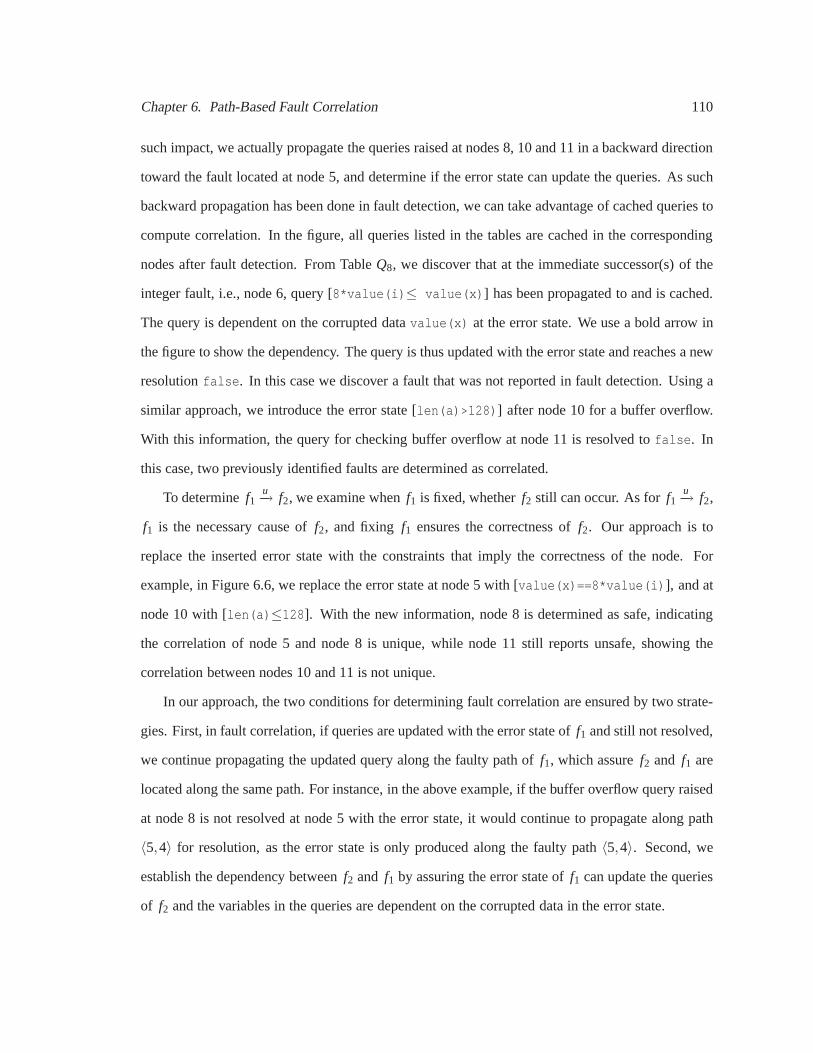
Chapter 6. Path-Based Fault Correlation 110
such impact, we actually propagate the queries raised at nodes 8, 10 and 11 in a backward direction
toward the fault located at node 5, and determine if the errorstate can update the queries. As such
backward propagation has been done in fault detection, we can take advantage of cached queries to
compute correlation. In the figure, all queries listed in thetables are cached in the corresponding
nodes after fault detection. From TableQ8, we discover that at the immediate successor(s) of the
integer fault, i.e., node 6, query [8*value(i)≤ value(x)] has been propagated to and is cached.
The query is dependent on the corrupted datavalue(x) at the error state. We use a bold arrow in
the figure to show the dependency. The query is thus updated with the error state and reaches a new
resolutionfalse. In this case we discover a fault that was not reported in fault detection. Using a
similar approach, we introduce the error state [len(a)>128)] after node 10 for a buffer overflow.
With this information, the query for checking buffer overflow at node 11 is resolved tofalse. In
this case, two previously identified faults are determined as correlated.
To determinef1u−→ f2, we examine whenf1 is fixed, whetherf2 still can occur. As forf1
u−→ f2,
f1 is the necessary cause off2, and fixing f1 ensures the correctness off2. Our approach is to
replace the inserted error state with the constraints that imply the correctness of the node. For
example, in Figure 6.6, we replace the error state at node 5 with [value(x)==8*value(i)], and at
node 10 with [len(a)≤128]. With the new information, node 8 is determined as safe, indicating
the correlation of node 5 and node 8 is unique, while node 11 still reports unsafe, showing the
correlation between nodes 10 and 11 is not unique.
In our approach, the two conditions for determining fault correlation are ensured by two strate-
gies. First, in fault correlation, if queries are updated with the error state off1 and still not resolved,
we continue propagating the updated query along the faulty path of f1, which assuref2 and f1 are
located along the same path. For instance, in the above example, if the buffer overflow query raised
at node 8 is not resolved at node 5 with the error state, it would continue to propagate along path
〈5,4〉 for resolution, as the error state is only produced along thefaulty path〈5,4〉. Second, we
establish the dependency betweenf2 and f1 by assuring the error state off1 can update the queries
of f2 and the variables in the queries are dependent on the corrupted data in the error state.

Chapter 6. Path-Based Fault Correlation 111
6.3.2.2 Correlation via Feasibility Change
Figure 6.7: Correlation via Feasibility Change
The error state off1 also can impactf2 indirectly by changing the conditional branchesf2
depends upon, shown in Figure 6.7. The program is a simplifiedversion of Figure 6.1. Under
Fault Detection, we list the query transitions to detect infeasible paths and faults. UnderFault
Correlation, we show the query update in fault correlation. In this example, our focus is to present
how an integer error found at node 3 changes the branch correlation at node 4 and then impacts other
faults. An error state [value(i)<0] is modeled after node 3. Examining cached query at node 4,
we find that the error state can update the branch query [value(i)>0] and resolve it tofalse. The
change of the resolution implies that the path this query propagated along is no longer infeasible as
identified before. Therefore, all the queries that are control dependent on this branch are potentially
impacted, and we need to evaluate all the queries cached at node 4 for new resolutions. For example,

Chapter 6. Path-Based Fault Correlation 112
we restart the query [value(p)6=0] from node 4 and resolve it at node 1 asfalse, and a null-pointer
dereference is discovered. Similarly, we restart the buffer overflow query [value(i)>0] at node 4,
where we find the query is resolved asfalse with the information from the error state. In this case,
the error state of the integer fault first impacts the branch and activates the propagation of the query
at node 4; then the error state also has a direct impact on the query and changes its resolution to
false.
6.3.3 The Algorithm of Fault Correlation
For identifying fault correlations, Algorithm 4 takes the inputsic f gandn, whereic f g represents
the ICFG with fault detection results (including the cachedqueries and marked faulty paths), and
n is the node where the fault is detected. Our goal is to identify all the correlations for the fault at
noden.
At line 2, we model the error state. For each query cached at the immediate successor(s) of
the fault, we identify queries that are dependent on the error state. See lines 3–5. If the query is
resolved after updating with the error state, we add it to theset of resolved queriesA at line 7.
Otherwise, if the updated query was used to compute faults, we add it to the listFQ at line 8. If
the query was used to compute branch correlation, we add it tothe list IQ at line 10. Lines 11–12
collect queries stored at the branchq′.raise. The faults associated with these queries are potentially
impacted by the feasibility change, and thus need to be reevaluated. After queries are classified to
the listsFQ andIQ, we compute the feasibility change at line 17 usingIQ and then determine the
impact of the error state directly on the faults at line 18 using FQ.
The determination of the resolutions of updated queries is shown inResolve at line 19. The
analysis is backwards. At line 21, we first propagate the queries to the predecessors of the faulty
node. We then use a worklist to resolve those queries at lines23–28.Propagate at line 30 indicates
that we need to only propagate the queries along feasible andfaulty paths. After a query is resolved
at line 26, we identify paths and mark them on ICFG at line 29. For branch query, they are adjusted
infeasible paths, while for queries to determine faults, the paths show where the correlation occurs.

Chapter 6. Path-Based Fault Correlation 113
Input : ICFG with fault detection results (ic f g);faulty node (n)
Output : Correlations forn
1 initialize IQ = {} and FQ = {}2 er = ModelErrState (n);3 foreachm∈ Succ(n) do4 foreachq∈ Q[m] do5 q′ = UpdateWithErrState (er, q);6 if q′ 6= q then7 if q′.an = resolvedthen addq′ to A8 else if IsFaultQ(q’) then addq′ to FQ9 else
10 addq′ to IQ11 foreachx∈ Q[q′.raise] do12 if IsFaultQ( x) then addx to FQ13 end14 end15 end16 end17 Resolve(IQ)18 Resolve(FQ)
19 ProcedureResolve(querylistQ)20 foreachq∈ Q do21 foreach p∈Pred(n) do Propagate(n, p, q)22 end23 while worklist 6= /0 do24 remove (i, q) from worklist25 UpdateQ(i, q)26 if q.an = resolvedthen addq to A27 else foreachp∈Pred(i) do Propagate(i, p, q)28 end29 IdentifyPath(A)
30 ProcedurePropagate(nodei, nodep, queryq)31 if OnFeasiblePath(i, p, q.ipp)∧32 OnFaultyPath(i, p, q. f pp) then33 add (p, q) to worklist
Algorithm 4: Compute Fault Correlations
6.4 Correlation Graphs
Our algorithm computes the correlation between pairs of faults. We integrate individual fault
correlations in a graph representation to present correlations among multiple faults and along dif-
ferent paths for the whole program.

Chapter 6. Path-Based Fault Correlation 114
Definition 6.3: A correlation graphis a directed and annotated graphG = (N,E), whereN is
a set of nodes that represent the set of faults in the program and E is a set of directed edges, each
of which specifies a correlation between two faults. Theentry nodesin the graph are nodes that
do not have incoming edges, and they are the faults that occurfirst in the propagation. Theexit
nodesare nodes without outgoing edges, and they are the faults that no longer further propagate.
Annotations for a node introduce information about a fault,including its location in the program,
the type, and the corrupted program objects at the fault if any. Annotations for the edge specify
whether the correlation is unique and also the paths where the correlation occurs.
(a) graph for Figure 6.1 (b) graph for Figure 6.3
(c) graph for Figure 6.4
Figure 6.8: Correlation Graphs for Examples: + marks a correlation that is not unique
The correlation graph groups faults of the related causes for the program. The entry nodes of
the graph and the nodes whose correlation are not unique should be focused to find root causes.
Using the correlation graph, we can reduce the number of faults that need to be inspected in order
to fix all the faults. In Figure 6.8, we show the correlation graphs for examples we presented before,

Chapter 6. Path-Based Fault Correlation 115
Figure 6.8(a) for Figure 6.1, 6.8(b) for Figure 6.3, and 6.8(c) for Figure 6.4.
In Figure 6.1, we have shown a correlation of integer fault and null-pointer dereference along
path 〈1,2,5〉. Actually the integer fault at node 2 also correlates with a buffer bounds error at
node 5 along path〈(1−5)+,1,2,5〉. See Figure 6.8(a). If the buffer bounds error continues to
cause privilege elevation, the correlation graph would show a chain of correlated faults to help
understand the exploitability of the code. On the other hand, if both the null-pointer dereference
and buffer underflow at node 5 are reported via a dynamic detector, using the correlation graph,
we are able to know the two failures are attributable to the same root cause and can be fixed by
diagnosing the integer fault at node 2. Similarly, the relationship of the resource leak and infinite
loop shown in Figure 6.3 is depicted in Figure 6.8(b).
The correlation graph in Figure 6.8(c) integrates all correlations for 7 buffer overflows in Fig-
ure 6.4. To use this graph for diagnosis, we start from the entry node of the graph, as it indicates
the root cause of all 7 correlated faults. Diagnosing the entry node we discover that when the input
FileData.cFileName is copied to thefilename buffer at line 2, no bounds checking is applied.
We thus introduce a fix for line 2. The correlation graph indicates that all other correlated faults can
be fixed except the fault at line 14, as in the graph, the edge from the fault at line 2 to the fault at
line 14 indicates the existence of an additional root cause.We thus diagnose line 14 and introduce
the second fix.
6.5 Experimental Results
To demonstrate that we are able to automatically compute fault correlations and show that fault
correlations are helpful for fault diagnosis, we implemented our techniques and chose three types
of common faults as case studies: buffer out-of-bounds, integer truncation and signedness errors,
and null-pointer dereference. In the experiments, we first run fault detection and update the ICFG
with faults detected. We model the error state of integer andbuffer faults using the approaches
shown in Table 6.1 and then determine the fault correlation.It should be noted that although in our
experiments, we use our fault detector to identify faults and then compute fault correlations, our

Chapter 6. Path-Based Fault Correlation 116
technique is applicable when faults are provided by other tools. We used a set of 9 programs for
experimental evaluation: the first five are selected from benchmarks that are known to contain 1–2
buffer overflows in each program [Lu et al., 2005, Zitser et al., 2004]; the rest are deployed mature
applications with a limited number of faults reported by ourfault detector. The experimental data
about fault correlation are presented in the following foursections. The results have been confirmed
by manual inspection.
6.5.1 Identification of Fault Correlations
In the first experiment, we show that fault correlations can be automatically identified. Table 6.3
displays identified correlations. In the first column of the table, we list the 9 benchmark programs.
UnderFaults from Detection, we display the number of faults identified for each program in our
fault detection. Buffer bounds errors are reported in Column buf/corr. Integer faults are listed in
Columnint/corr and the null-pointer dereferences are shown in Columnptr/corr. In each column,
the first number gives the identified faults and the second lists the number of detected faults that
are involved in fault correlation. Our fault detector reports a total of 80 faults of three types, 51 of
which are involved in fault correlation.
UnderFault Correlations, we list the number of pairs of faults in the program that are found
to be correlated. For example, underint_buf, we count the pairs of correlated faults where the
cause is an integer fault, which leads to a buffer overflow. Comparing the integer faults involved in
the correlations underint_buf and int_ptr with the ones found in fault detection, we can prioritize
the integer faults with severe symptoms. In the last column of Fault Correlations, we give a total
number of identified correlations. In our experiments, we found fault correlations for 8 out of 9
programs. Correlations occur between two integer faults, an integer fault and a buffer overflow, an
integer fault and a null-pointer dereference, two buffer overflows, as well as a buffer overflow and
an integer fault.
The experiments also validate the idea that the introduction of error states can enable more
faults to be discovered. We identify a total of 25 faults during fault correlation from 5 benchmarks,
including buffer overflows, integer faults, and null-pointer dereferences, shown underFaults during

Chapter 6. Path-Based Fault Correlation 117
Correlation.
Consider the benchmarkgzip-1.2.4 as an example. We discover a total of 25 faults and
22 pairs of them are correlated. A new buffer overflow is foundafter introducing the impact of
an integer violation. Buffer overflow correlates with integer fault whenstrlen is called on an
overflowed buffer which later is assigned to a signed integerwithout proper checking. We also
found that the new faults generated during fault correlation can further correlate with other faults.
In putty-0.56, two integer faults found during fault correlation resulted from another integer fault
are confirmed to enable a buffer overflow. The propagation of these faults explains how the buffer
overflow occurs.
Table 6.3: Automatic Identification of Fault CorrelationsBenchmarks
Faults from Detection Fault Correlations Faults duringbu f/corr int/corr ptr/corr int_int int_bu f int_ptr bu f_bu f bu f_int total Correlation
wuftp:mapping-chdir 4/4 0 0 0 0 0 7 0 7 0sendmail:tTflag-bad 0 3/1 0 0 1 0 0 0 1 1 (buf)sendmail:ge-bad 4/4 0 1/0 0 0 0 3 0 3 0polymorph-0.4.0 8/8 0 0 0 0 0 13 0 13 0gzip-1.2.4 9/9 15/7 0 0 7 0 9 6 22 1 (buf)
ffmpeg-0.4.8 0 6/2 1/0 0 10 1 0 0 11 11 (1 ptr, 10 buf)tightvnc-1.2.2 0 11/8 0 9 8 0 0 0 17 7 (2 int, 5 buf)putty-0.56 7/6 4/2 0 3 3 0 4 0 10 5 (3 int, 2 buf)apache-2.2.4 0 2/0 5/0 0 0 0 0 0 0 0
6.5.2 Characteristics of Fault Correlations
We also collected the data about the characteristics of fault correlations, shown in Table 6.4.
In ColumnUnique/Not, we count, for all the correlations identified, how many are uniquely cor-
related (see the first number in the column) and how many are not (see the second number). The
data demonstrate that both types of correlations exist in the benchmarks. ColumnDir/Indir shows
whether a correlation occurs directly between two faults orindirectly as a result of feasibility
change. The first number summarizes the direct correlationsand the second number counts the
indirect ones. The results show that most correlations are discovered via direct query interactions,
and only two programs report the correlations identified from feasibility change. We also inves-
tigated the distances between the correlated faults. The experimental data underInter/Intra show
that along the correlated paths, the two faults can be located either intraprocedurally or interpro-

Chapter 6. Path-Based Fault Correlation 118
cedurally. Therefore an interprocedural analysis is required for finding all correlations. A related
metric is the distance of correlated faults along the correlation paths in terms of number of proce-
dures. ColumnCorr-Proc gives both the minimum and maximum numbers of procedures between
two correlated faults in the benchmark. We are able to find thecorrelation where two faults are 19
procedures apart.
Table 6.4: Characteristics of Fault CorrelationsBenchmarks Unique/Not Dir/Indir Inter/Intra Corr-Procwuftp:mapping-chdir 4/3 7/0 7/0 1–10sendmail:tTflag-bad 1/0 1/0 0/1 1–1sendmail:ge-bad 0/3 3/0 0/3 1–1polymorph-0.4.0 11/2 13/0 8/5 1–3gzip-1.2.4 12/10 21/1 15/7 1–19
ffmpeg-0.4.8 11/0 1/10 0/11 1–1tightvnc-1.2.2 14/3 17/0 16/1 1–2putty-0.56 10/0 10/0 2/8 1–3
6.5.3 Computing Correlation Graphs
A correlation graph is built for each benchmark in the experiments. In Table 6.5, we first give
the size of benchmarks in terms of thousands lines of code. InColumnNode, we report the total
number of nodes in the correlation graph. The nodes include faults identified from fault detection
and fault correlation. The types of identified faults are listed in ColumnType. For example, for
the programffmpeg-0.4.8, we find faults of all three types. In ColumnGroup, we provide the
number of groups of correlated faults for each program. We obtained the number by counting the
connected components in each correlation graph. The results show that although the number of
faults can be high in a program, many of the faults can be grouped and diagnosed together. For
7 out of 9 programs, the faults are clustered to less than a half of fault groups which will assist
diagnosis.
Under Analysis Cost, we report the analysis costs for computing correlation graphs, includ-
ing the time used for detecting faults (see the first number inthe column) and the time used for
computing fault correlations (see the second number). The machine we used to run experiments
is the Dell Precision 490, one Intel Xeon 5140 2-core processor, 2.33 GHz, and 4 GB memory.

Chapter 6. Path-Based Fault Correlation 119
The experimental data show that the analysis cost for fault detection is not always proportional to
the size of the benchmarks; the complexity of the code also matters. For example, the analysis for
sendmail:tTflag-bad takes a long time to finish because all the faults are related to several nested
loops. The additional costs of computing fault correlations for most of the benchmarks are under
seconds or minutes, except forgzip-1.2.4, which contains the most faults among the benchmarks
and many faults are found to impact a large chunk of the code inthe program. The data suggest that
the important factors that determine the analysis cost of fault correlation are the number of faults
and the complexity of their interactions.
Table 6.5: Correlation Graphs and their Analysis CostsBenchmarks Size(kloc) Node Type Group Analysis Cost
wuftp:mapping-chdir 0.2 4 1 1 3.9 m/43.2 ssendmail:tTflag-bad 0.2 4 2 3 108.0 m/5.6 ssendmail:ge-bad 0.9 5 2 2 10.8 s/3.7 spolymorph-0.4.0 0.9 8 1 1 39.4 s/9.3 sgzip-1.2.4 5.1 25 2 9 29.3 m/90.0 m
ffmpeg-0.4.8 39.8 18 3 7 114.2 m/3.4 mtightvnc-1.2.2 45.4 18 2 6 60.3 m/2.4 mputty-0.56 60.1 16 2 7 62.8 m/1.2 mapache-2.2.4 268.9 7 2 7 217.8 m/2.1 s
6.5.4 False Positives and False Negatives
In our experiments, both false positives and false negatives have been found. Because we
isolate don’t-know warnings for unresolved library calls,loops and pointers, our analysis does not
generate a large number of false positives. In fault correlation, we consider the following two cases
as false positives: 1) at least one of the faults involved in correlation is false positive; and 2) both
faults in the correlation are real faults, but they are not correlated. In our buffer overflow detection,
we report a total of 7 false positives for all programs, 1 fromsendmail:tTflag-bad, 4 from
gzip and 2 fromputty. For integer fault detection, we report a total of 10 false positives, 3 from
sendmail:tTflag-bad, 2 from polymorph, 2 from ffmpeg, 1 from putty and 2 fromapache.
We find 25 correlations reported are actually false positives, 23 of which are related to case (1),
and 2 to case (2) where the correlation paths computed are confirmed as infeasible. However, we
did not find that any new faults reported during fault correlation (see the last column in Table 6.3)

Chapter 6. Path-Based Fault Correlation 120
are false positives. Interestingly, we found false positive faults can correlate with each other and
thus be grouped. In our implementation, we have applied suchcorrelations to quickly remove false
positives and improve the precision of our analysis. We exclude the false positives when reporting
the faults and fault correlations in Tables 6.3, 6.4 and 6.5.
We miss fault correlations mainly in two cases: 1) we report correlated paths between two
faults as don’t-know; and 2) the correlation occurs among the types of faults not investigated in our
experiments. For example, in the benchmarktightvnc-1.2.2, three integer faults are reported as
not correlated, shown underFaults from Detectionin Table 6.3; however, our manual inspection
discovers that these faults can cause buffer read overflow, which was not considered in our fault
detection.
6.6 Conclusions
As faults become more complex, manually inspecting individual faults becomes ineffective. To
help with diagnosis, this chapter shows that identifying a causal relationship among faults helps
understand fault propagation and group faults of related causes. With the domain being statically
identifiable faults, this chapter introduces definitions offault correlation and correlation graphs,
and presents algorithms for their computation. Our experiments demonstrate that fault correlations
exist in real-world software, and we can automatically identify them. The benchmarks used in our
experiments are mature applications with few faults. However, determining correlation is espe-
cially important for newly developed or developing software which would have many more faults.
Although the fault correlation algorithm is tied to our fault detection for efficiency, a slightly mod-
ified correlation algorithm would work if faults are discovered by other tools and presented to the
correlation algorithm.

Chapter 7
Path-Guided Concolic Testing
Concolic testing [Sen et al., 2005] has been proposed as an effective technique to automatically
test software. The goal of concolic testing is to generate test inputs to find faults by executing as
many paths of a program as possible. However, due to the largestate space, it is unrealistic to
consider all of the program paths for test input generation.Rather than exploring the paths based
on the structure of the program as current concolic testing does, in this research, we generate test
inputs and execute the program along the paths that have identified potential faults.
We present a path-guided testing technique that combines static analysis with concolic testing.
A novelty of our work is that our technique is path-based, i.e., we direct dynamic testing to the
path segments rather than a program point. Compared to program points, path information is more
precise, and can help further reduce the search space for test input generation.
This research addresses three challenges. Considering that the number of suspicious paths
can still be huge, we need to develop a representation of pathinformation used in testing. Also,
static analysis produces false positives and false negatives. We need to understand the impact of
the potential imprecision in guiding test input generation. Furthermore, not every execution that
exercises a faulty path necessarily triggers the fault; besides path constraints, we also need to track
fault conditions for test input generation.
Our technique proceeds in three steps. First, the program under test is analyzed by a path-
sensitive static analysis tool. Both the suspicious statement and corresponding path segments along
121

Chapter 7. Path-Guided Concolic Testing 122
which a fault could occur are identified, represented using apath graph. Second, reachability
relationships from each branch to these path segments are computed. In the third step, we execute
the program with an initial input, and use the reachability information and the path graph to select
the paths of interest. During execution, we generate test inputs that 1) can reach a suspicious
statement along a corresponding suspicious path segment, and 2) can trigger the fault condition at
the suspicious statement.
We have implemented our techniques in a tool called MAGIC (MArple-GuIded Concolic test-
ing). Currently, this tool handles buffer overflows for C programs; however the technique is applica-
ble for multiple types of faults, including both data- and control-centric faults. In our experiments,
MAGIC confirmed 73% of statically reported faults. It failedto trigger 5 static faults whose de-
tection requires an environment which is different from where MAGIC is running, and it missed 2
faults due to the capability of concolic testing. Compared to concolic testing, MAGIC found about
2.5 times more faults, and using the path information, MAGICtriggers the faults 1.1–66.3 times
faster over a set of benchmarks.
The main contributions of this chapter include:
• automatic test input generation to exploit statically identified faults,
• application of static path information for reducing the cost of dynamic testing,
• the implementation of the techniques for detecting buffer overflows, and
• an experimental study that demonstrates the effectivenessof our technique.
7.1 An Example
First, we use an example to intuitively explain the techniques. In Figure 7.1, we show a piece
of code adapted from the benchmark wu-ftp [Zitser et al., 2004]. This example contains three paths
and two buffer write statements at lines6 and10 respectively. A buffer overflow exists at line10.
Using this example, we compare how traditional concolic testing and our technique find this buffer
overflow.

Chapter 7. Path-Guided Concolic Testing 123
Applying concolic testing for buffer overflow [Xu et al., 2008], we first execute the program
with an initial input. We assume in the first run,argc=1, which means that no command line
argument is supplied to the program. Under this input, the program takes the execution path
〈2,3,4(T),5〉. During execution, the symbolic path constraint [argc !=2] is collected. As the goal
of concolic testing is to cover as many paths as possible, in the second run, the tester inverts the
path constraint to [argc=2], aiming to exercise the branch4(F). Suppose a command line argument
“a” is generated forargv[1]. Running this input, path〈2,3,4(F),6,7,8(F),10〉 is taken. Along this
path, the tester checks the buffer safety at lines6 and10, and determines that both lines 6 and 10
are safe for this execution. Meanwhile, the tester also derives that line 10 can be an overflow if
the length of argv[1] is larger than 8. Using this buffer overflow condition, the tester can generate
an input “aaaaaaaaa” forargv[1], which leads the execution to path〈2,3,4(F),6,7,8(F),10〉, and
exploits the buffer at line 10. Since there are still paths that have not been covered, the concolic
testing continues to invert the path constraint at line 8, aiming to take branch8(F). A string “.” is
generated as the input forargv[1] to exercise〈2,3,4(F),6,7,8(T),9〉.
Concolic testing terminates either when 1) no more new pathscan be further executed due to
incapability of solving complex constraints, 2) all of the paths in a program have been executed,
or 3) a time threshold is reached. Considering that there is an exponential number of paths, often
only a small portion of the program paths are actually covered by concolic testing [Godefroid et al.,
2005] [Sen et al., 2005]. For this example, concolic testingcovers all the three paths of the program
and generates a total of three test inputs. Buffer write statements at lines 6 and 10 are checked for
each path that exercises them.
Our observation is that not all of the buffer write statements are equally suspicious for buffer
overflows. Even for a suspicious statement, not all the pathsthat traverse it are faulty. To save the
cost of test input generation, we should direct the testing along suspicious paths.
Applying our technique, we first statically identify that line10 is suspicious for buffer overflow
along path segment〈6,7,8(F),10〉, and line6 is safe, which implies that no checks are needed
for this statement at run time. We then perform a reachability analysis, and find that branch4(F)
reaches the suspicious path segment, but branch4(T)cannot. Based on the above static information,

Chapter 7. Path-Guided Concolic Testing 124
1 main (i n t argc , char ∗∗ argv ) {2 char mapped_path [ 1 0 ] ;3 char ∗ pa th ;4 i f ( a rgc != 2 )5 re turn ;6 s t r c p y ( mapped_path , ‘ ‘ / ’ ’ ) ;7 pa th = argv [ 1 ] ;8 i f ( pa th [ 0 ] == ’ . ’ ) )9 re turn ;
10 s t r c a t ( mapped_path , pa th ) ;11 }
Figure 7.1: Comparing Concolic Testing and MAGIC Using an Example
we run a concolic testing. The program is first executed with no arguments along path〈2,3,4(T),5〉.
As branch4(F) can reach the suspicious path segment, we inverse the symbolic path constraint and
generate an input“a” . Under this input, the program executes〈2,3,4(F),6,7,8(F),10〉. Since the
suspicious path segment is traversed, the tester determines if the buffer overflow is triggered. As the
buffer overflow is not triggered under this input, the testerintegrates the buffer overflow condition
at line10, and generates a new input“aaaaaaaaaa” to exploit the buffer overflow.
With the static information, we do not need to explore the program nodes that cannot reach
the suspicious path segment, e.g., branch4(T). Only paths that cross a suspicious path segment
are checked for buffer overflow. For instance, no effort is needed to generate test input for path
〈2,3,4(F),6,7,8(T)〉. Testing can be terminated early when the potential faults are triggered. We
exploit the overflow at line10 by only generating two test inputs, and the possibility of buffer
overflow is checked only once along one path.
7.2 An Overview of MAGIC
This section provides a high level description of MAGIC, including the components of MAGIC
and their interactions.
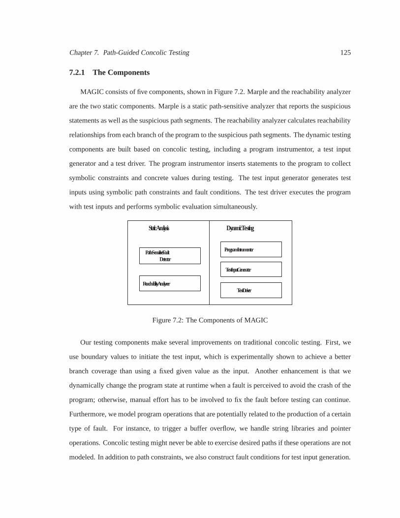
Chapter 7. Path-Guided Concolic Testing 125
7.2.1 The Components
MAGIC consists of five components, shown in Figure 7.2. Marple and the reachability analyzer
are the two static components. Marple is a static path-sensitive analyzer that reports the suspicious
statements as well as the suspicious path segments. The reachability analyzer calculates reachability
relationships from each branch of the program to the suspicious path segments. The dynamic testing
components are built based on concolic testing, including aprogram instrumentor, a test input
generator and a test driver. The program instrumentor inserts statements to the program to collect
symbolic constraints and concrete values during testing. The test input generator generates test
inputs using symbolic path constraints and fault conditions. The test driver executes the program
with test inputs and performs symbolic evaluation simultaneously.
S t a t i c A n a l y s i s
P a t h - S e n s i t i v e F a u l t D e t e c t o r
D y n a m i c T e s t i n g
R e a c h a b i l i t y A n a l y z e r
P r o g r a m I n t r u m e n t o r
T e s t I n p u t G e n e r a t o r
T e s t D r i v e r
Figure 7.2: The Components of MAGIC
Our testing components make several improvements on traditional concolic testing. First, we
use boundary values to initiate the test input, which is experimentally shown to achieve a better
branch coverage than using a fixed given value as the input. Another enhancement is that we
dynamically change the program state at runtime when a faultis perceived to avoid the crash of the
program; otherwise, manual effort has to be involved to fix the fault before testing can continue.
Furthermore, we model program operations that are potentially related to the production of a certain
type of fault. For instance, to trigger a buffer overflow, we handle string libraries and pointer
operations. Concolic testing might never be able to exercise desired paths if these operations are not
modeled. In addition to path constraints, we also constructfault conditions for test input generation.

Chapter 7. Path-Guided Concolic Testing 126
The goal is to ensure the generated inputs not only can exercise a desired path but also trigger faults.
7.2.2 The Workflow of MAGIC
As shown in Figure 7.3, MAGIC first statically analyzes the program and reports suspicious
statements and path segments. Based on the program source and the path segments, MAGIC runs
a reachability analysis to determine, for each branch, whether the execution at the branch is able to
reach any of the suspicious path segments. MAGIC instruments the program to collect information
needed at runtime. Testing runs on the instrumented programwith an initial test input. During
execution, the tester determines whether the current execution can traverse any suspicious path
segment. Meanwhile, the tester collects concrete and symbolic values; when a suspicious fault is
encountered, the symbolic constraints regarding path constraints and fault conditions are solved by
a constraint solver for potential test inputs. Testing terminates when a program input is discovered
that can trigger the fault, or the paths that traverse the setof suspicious path segments are all
examined, which show that the suspicious statement is likely safe along the reported suspicious
path segments. The details of static and dynamic componentsare presented in Section 7.3 and 7.4.
Figure 7.3: The Workflow of MAGIC

Chapter 7. Path-Guided Concolic Testing 127
7.3 Obtaining Static Path Information
In MAGIC, a program is first analyzed using our path-sensitive analysis to obtainsuspicious
statementsand correspondingsuspicious path segments. Here, we consider bothfaulty anddon’t-
knowpath segments reported by Marple as suspicious and any statement where a suspicious seg-
ment can traverse is asuspicious statement. In this section, we first describe our choice of static
information provided to dynamic testing, and we then present the reachability analysis customized
for our purpose.
7.3.1 The Choice of Path Information
To determine what path information we should provide to dynamic components, we first need
to understand the semantics of two types of suspicious path segments. In our analysis, a path
segment is determined as faulty if: 1) along the path segment, the fault always occurs independent
of program inputs, e.g., a buffer overflow with a constant string, or 2) there exists an entry point
along the path segment, where users can supply an input to trigger the fault, e.g., a buffer overflow
with an external string. As its determination is independent on any other information beyond the
path segment, any execution that traverses the faulty path segment (with a proper input supplied at
the entry point along the path segment for the second case) can trigger the fault. A don’t-know path
segment is determined when the query encounters don’t-knowfactors. If the don’t-know factors
are resolved, the query is potentially propagated further before being determined as faulty, in which
case, the don’t-know path segment can be viewed as a partial faulty path segment. Some of the
don’t-know paths can be safe and thus executions along don’t-know paths do not necessarily trigger
the fault.
There is also the choice on the number of suspicious path segments we should present. In test-
ing, we only need to demonstrate the exploits of the buffer overflow along one execution. However,
presenting one path segment for test input generation is notsufficient. The reasons are twofold.
First, static information can be imprecise. For example, even a buffer overflow potentially occurs at
the statement, a suspicious path segment randomly picked from the static results can be infeasible.

Chapter 7. Path-Guided Concolic Testing 128
Although we have applied a static analysis to remove some of the infeasible paths, infeasible path
detection is an undecidable problem, and we can not remove all of them for a program. The second
reason is that concolic testing is not always able to generate a test input to exercise a given path,
as some of the symbolic constraints are too complex to solve.We also can choose to enumerate
all of the suspicious path segments; however, this solutionis not scalable as there potentially exists
a large number of suspicious path segments, and both storingand accessing them at runtime can
incur unacceptable overhead. There is also the choice of using a fixed number of path segments.
The challenge is to determine a reasonable number and also strategies to select the path segments.
In our work, we appliedpath graphs(see Definition 3.6) to represent a set of suspicious path
segments that end at the same suspicious statement. Each path graph contains a type of paths for
a fault. The path graphs are generated by Marple. In Marple, computation of path graphs is a
forward analysis following the fault detection. As shown inChapter 4, in fault detection, queries
are propagated backwards for resolutions. During propagation, queries are stored at each program
node. To construct the path graph, we start at the node where afault or don’t-know resolution
was derived. These nodes are first added to the graph as entry nodes. Marple then determines for
each successor, whether the query at the current node was actually propagated from either of its
successors; if so, the successor(s) is added to the graph, and an edge between the predecessor and
successor is also added into the graph. The process continues until the suspicious statement, where
the query was initially raised, is reached.
For example, we show in Figure 7.4 (a) and (b), two suspiciouspath segments ending at the
same suspicious statementr. s1 ands2 are two resolution points. Figure 7.4(c) is the path graph
constructed for the suspicious path segments in (a) and (b).
The choice here is whether we use the annotations on the path graph in testing. The tradeoff is
that using the annotated path graph, more information needsto be compared at runtime, incurring
additional performance overhead; if annotations on the edges are not considered when we use the
path graph, some path-sensitive information is potentially lost and we potentially lead the test input
generation to some safe path. In MAGIC, we use the path graphswithout annotations.
In concolic testing, generating an input that potentially covers a path segment in a path graph

Chapter 7. Path-Guided Concolic Testing 129
r r
s 1 s 2
l 1
l 2
l 3
l 2
r
s 1
l 1
l 2
s 2
l 3
( b ) ( a ) ( c )
Figure 7.4: A Path Graph for Two Suspicious Path Segments
is more efficient than generating an input based on individual path segments. The reasons are as
follows. Concolic testing generates a test input for a new path by inverting a particular branch.
Given a path, concolic testing potentially needs to invert aset of branches from an initial execution,
and take several iterations before a desired test input can be generated. On the other hand, if a set
of path segments are given in a graph, concolic testing has more flexibility in choosing which path
to exploit. The testing terminates as long as any suspiciouspath segment in the graph is triggered.
7.3.2 Reachability Analysis
In our dynamic testing, we need to generate test input for thepath that starts at the beginning
of the program and traverses any path segment in path graphs.We use reachability analysis to
determine whether any of the branches in a program can actually reach the entries of the path
graphs; if not, we terminate the test input generation alongthe corresponding branch.
Algorithm 1 takes the interprocedural control flow graph of aprogram (ICFG), and a set of path
graphs reported by our analysis as inputs. The results of reachability are stored in a map, where for
each branch, we report a set of entries of path graphs that thebranch can reach. In Algorithm 1,
lines1-5determine for each branch statement, whether the entries ofthe path graph can be reached.
The core analysis is achieved in a recursive procedureReach(see line8). At line 10, we get the
immediate successors of the current branchb. For each successorbi , if bi is an entry of the path
graph, then we add it to the setreachableat line13; otherwise, we recursively call procedureReach
on bi at line14.

Chapter 7. Path-Guided Concolic Testing 130
Algorithm 1. Calculating Reachability Relationship
INPUT : icfg: the ICFG of the program,G: a set of path graphs
OUTPUT: reachability: a map<branch,<set> entries of path graphs>
1 for eachbranch statementb in icfg
2 initialize reachable {}
3 Reach(b, &reachable)
4 reachability[b] := reachable
5 end
6 return reachability
7
8 PROCEDURE: Reach(statementb, setreachable)
9 //recursively traverse statements can be reached from b
10 setsuccessors:= immediate successor statements ofb in icfg
11 for eachstatementbi in successors
12 if bi is an entry of any path graphg∈ G
13 reachable.push(bi)
14 Reach(bi, reachable)
15 end
16 end
7.4 Dynamic Testing
In our dynamic testing, we apply the reachability information and the suspicious statements/-
path segments computed above. Since collecting and solvingsymbolic constraints are important
for generating the test input, we symbolically model fault conditions, as well as the semantics of
certain program statements that are relevant to trigger faults. In this section, we first present the
goals of program instrumentation and techniques. We then show our modeling techniques for four
types of program statements. Finally, we explain how the static information is used to generate test
inputs.

Chapter 7. Path-Guided Concolic Testing 131
7.4.1 Program Instrumentation
Instrumentation is inserted in the program source. Dynamictesting runs on the instrumented
programs and takes actions according to the instrumentation. A general goal is to collect symbolic
path constraints and fault conditions needed for test inputgeneration at runtime. Four types of
actions are applied based on the types of program statements:
• if an input statement is encountered, we add a new input variable into asymbolic map. The
symbolic map records the symbolic values of current live variables, and also symbolic path
constraints and fault conditions;
• if a binary and unary variable operation is met, we record thesymbolic values of the results;
• for conditional branches, we record the conditions for bothfalse and true branches in the
symbolic map; and
• for a suspicious statement, such asstrcpyor pointer dereferences, we construct fault condi-
tions to determine inputs that can trigger the fault.
7.4.2 Buffer Overflow Vulnerability Model
One main difference of MAGIC and concolic testing is that MAGIC is focused to trigger partic-
ular types of fault. Here, we describe the vulnerability model we developed for buffer overflow. In
this model, we provide a mapping from a buffer write statement to an overflow condition. We also
provide the actions we take at statements related to buffer and pointer operations. For each buffer,
we not only consider the buffer size and the string length, but also the contents of the buffer up to a
certain number of bytes. We specify a buffer using a 3-tuple (size, L, C), where:
• sizeis a symbolic expression for the size of the buffer;
• L = { len1, len2, ..., lenn} is a set of symbolic expressions representing the lengths of strings
stored in the buffer, as shown in Figure 7.5. Since′\0′ can occur multiple times in a buffer, we
record string lengths that are relevant to every′\0′ for precision. Dependent on the location
of the pointerp to the buffer, the string obtained viap can be relevant to any of recorded
lengths.

Chapter 7. Path-Guided Concolic Testing 132
Table 7.1: Modeling Buffer Overflow ConditionsSuspicious Operations Overflow Conditions
Supposepd = (addrd, o f fd)Supposeps = (addrs, o f fs)
strcpy(pd, ps)
(bd (sized, Ld, Cs) := δ(addrd)) 6= null;(bs (sizes, Ls, Cs) := δ(addrs)) 6= null;
Len(bs, ps) - o f fs >= sized - o f fdSupposepd = (addrd, o f fd)Supposeps = (addrs, o f fs)
strcat(pd, ps)
(bd (sized, Ld, Cs) := δ(addrd)) 6= null;(bs (sizes, Ls, Cs) := δ(addrs)) 6= null;
Len(bs, ps) - o f fs + Len(bd, pd) >= sizedSupposep = (addr, o f f )
*p := var(b (size, L, C):= δ(addr)) 6= null;
off > size
• C = c1, c2, ...,cv is a sequence of symbolic expressions representing the firstv characters of
the buffer [Xu et al., 2008]. The tradeoff here is that the more content of a buffer is modeled,
more precise the symbolic analysis can achieve, however, with higher overhead.
l e n 1
l e n 2
b u f f e r
p o i n t e r p
\ 0 \ 0
p o i n t e r p
Figure 7.5: Multiple Strings in a Buffer
We use a pair (addr, off) to specify a pointer to a buffer, whereaddr is the beginning of the
buffer andoff specifies the symbolic offset fromaddr. In Table 7.1, we show how buffer overflow
conditions can be constructed based on the type of program statements at runtime. In the first
column, we show three examples of suspicious statements. Weexplain the construction of buffer
overflow conditions in the second column. Consider the first row of the table as an example.ps
and pd are two pointers. A string in the buffer pointed to byps is copied to the buffer pointed to
by pd. At runtime, when such a suspicious statement is encountered, we first find in the symbolic
map the buffers associated withps andpd. This action is specified usingδ in the second column. If
the mapping is successful, shown asbd 6= null andbs 6= null in the table, we determine whether the
string fromps copied topd potentially cause an overflow (see Figure 7.6).

Chapter 7. Path-Guided Concolic Testing 133
o f f d
s i z e d
o f f s
l e n s = L e n ( b s , p s )
\ 0
b d
b s
Figure 7.6: Buffer Overflow Condition
In the figure, we show that the available buffer space is[sized −o f fd]. The string being copied
has a length of[lens−o f fs], wherelens represents the length of the string stored in buffers. As we
mentioned in Figure 7.5, multiple string lengths can be recorded for a buffer, and we need to select
a proper length depending on the location of the pointer. We useLen(bs, ps) to represent this action.
The second column first row in the table indicates that if the string length is larger than or equal to
the available buffer size, a buffer overflow can occur.
Besides operations modeled by concolic testing [Sen et al.,2005], our testing components also
model additional buffer and pointer operations. Table 7.2 presents a partial list. In the first column,
we present the type of program statements, and in the second column, we specify actions MAGIC
takes at the statement to construct the symbolic map. Consider the first row of the table. When
the program executes the statementp (addr, off) := input(size), MAGIC creates a new bufferb on
the symbolic map. The three parameters of a buffer are initialized: the size of the buffer issize,
a string length is alsosize, and the firstn bytes of characters are set based on the input string.
After the buffer is created, MAGIC establishes a mapping between the buffer and the pointer using
addr:=&b andoff:=0.
7.4.3 Path-Guided Test Input Generation
Algorithm 2 takes the path graphs of suspicious path segments reported by Marple, and gener-
ates the program inputs that can trigger faults.

Chapter 7. Path-Guided Concolic Testing 134
Table 7.2: Symbolic Semantics of String and Pointer OperationsOperations Symbolic Semantics
p (addr, off) := input(size)create a bufferb (size, {size}, { c1, c2, ...,cn}),addr := &b, off := 0
p (addr, off) := malloc(size)create a bufferb (size, {}, {}),addr := &b, off := 0
supposep = (addr, off) b := δ(addr)free(p) deleteb
supposestr = (addr, off) create a new bufferb (size, {size}, {}),char str[size] addr := &b, off := 0
supposepd = (addrd, o f fd)supposeps = (addrs, o f fs)
pd := ps ± vaddd := adds, o f fd = o f fs ± v
supposep = (addr, off) b (size, L, C):= δ(addr)*p := ’\0’ L := L ∪ { off}
At line 2, initial program inputs are generated. Primitive input variables are given value0, and
strings are initialized as empty strings. If boundary values of the inputs are known, MAGIC uses
their lower and upper bounds.
In the second step, MAGIC executes the program with the generated inputs (seeRun_Program
at line3). During execution, MAGIC collects both the branches that the execution covers and the
symbolic path constraints at the branches. When a path is discovered to traverse a suspicious path
segment in any given path graph, MAGIC determines if a bufferoverflow occurs; if not, MAGIC
integrates the buffer overflow conditions with a set of path constraints and generates a new test input.
If a buffer overflow is confirmed, MAGIC removes the path graphcorresponding to this suspicious
statement. Also, when a buffer overflow is determined, MAGICallocates a new memory space for
the buffer with the overflowed size and continues the execution, in an attempt to trigger more faults
along the same execution. When the execution terminates, westore a sequence of branches and
symbolic path constraints, collected along the execution,into the branch listB and the constraint
list C.
Path_Guided_Searchat line6 uses the branch listB and the constraint listC collected from the
previous execution to generate test inputs that excise the suspicious paths. Thefor loop at line8
examines the collected branch one by one in a reverse order; for each branch, MAGIC determines

Chapter 7. Path-Guided Concolic Testing 135
whether itspaired branchis either able to reach the entries of any path graph inG (see line11) or
on a suspicious path segment (see line15). If so, at line21, MAGIC attempts to generate a new test
input using a set of path constraints collected along〈B[1],B[2], ...,B[i −1]〉 with the inverted path
constraint at branchB[i]. The generated input at line23executes path⟨
B[1],B[2], ...,B[i −1],B[i]⟩
.
If the current branch cannot reach the entries of the path graphs or is not on any suspicious path
segment, MAGIC proceeds to examine the next branch at line8 in the same way. The testing
process terminates when all suspicious statements are triggered or all suspicious path segments are
covered.

Chapter 7. Path-Guided Concolic Testing 136
Algorithm 2. Path-Guided Test Input GenerationINPUT : G{g1, g2, ...,gl }: a set of path graphs of suspicious path segments
1 initialize branch list B {}andconstraint list C {}
2 I = GenInitInput()
3 Run_Program(I, &B, &C)
4 Path_Guided_Search(B, C)
5
6 PROCEDURE: Path_Guided_Search(branchlistB, constraintlistC)
7 bool inversePath:= false
8 for (i:=sizeOf(B); i >= 1 ; i- -)
9 get the PairedBranchB[i]
10 for eachsuspicious path graphgk in G
11 if B[i] can reach any stop point ingk
12 inversePath:= true
13 break
14 end
15 else ifpath⟨
B[1], ...B[i-1],B[i]⟩
traverses a path segment ingk
16 inversePath:= true
17 break
18 end
19 end
20 if (inversePath= true)
21 I’ := solve (C[1] ∩ C[2] ∩ ... ∩ C[i-1] ∩ ¬ (C[i]))
22 initialize branch list B’ {} andconstraint list C’ {}
23 Run_Program(I’ , &B’ , &C’ )
24 Path_Guided_Search(B’, C’)
25 end
26 end
27 end

Chapter 7. Path-Guided Concolic Testing 137
7.5 Implementation and Evaluation
We implemented MAGIC for testing buffer overflows. Our goalsare to evaluate its capability
for generating inputs to detect and trigger faults and also to determine its performance. For compar-
ison, we also constructed two other tools. Tool I implementsthe techniques of SPLAT [Xu et al.,
2008], which model buffer lengths and the first several bytesof buffer content on top of basic con-
colic testing to trigger buffer overflows. Different from MAGIC, it does not use boundary values as
initial inputs, and terminates when a fault is found. In the experiments, we needed to fix the fault
and run the tool again until no more faults were found. We constructed Tool II by isolating the dy-
namic testing components from MAGIC; that is, it does not useany static information. Comparing
Tool II and MAGIC, we can determine the usefulness of the pathinformation in guiding test input
generation.
MAGIC is implemented on top of CREST [Burnim and Sen, 2008] and Marple [Le and Soffa,
2008]. Both MAGIC and Tool I are implemented using MicrosoftPhoenix SDK1, and applied
the Yices constraint solver2. The machine used for experiments is the Intel Duo Core 2.26 GHz
processor with 2GB memory. We selected a set of benchmark programs, including wu-ftp:mapping-
chdir, sendmail:ge-bad, polymorph-0.4.0 and gzip-1.2.4.The first two are buffer overflow bench-
marks [Zitser et al., 2004], containing typical and realistic buffer overflows. Polymorph-0.4.03
is a real-world program, used to simplify file names in UNIX. Gzip-1.2.44 is a file compression
program.
We ran a preliminary set of experiments to determine the timethreshold we could use for the
tools. The experimental results show that for all of the benchmarks, testing either terminates within
1500seconds, or is no longer able to trigger more faults beyond1500seconds. Thus, in our exper-
iments, we decided to double the number and set the time threshold at3000seconds for all three
tools. The goal is to ensure that for most of the benchmarks, testing terminates before reaching
this threshold, and even when the termination is forced by the time threshold, the number of faults
1http://connect.microsoft.com/Phoenix2http://yices.csl.sri.com/3http://sourceforge.net/projects/polymorph/4http://www.gzip.org/

Chapter 7. Path-Guided Concolic Testing 138
reported by the tools reflect the actual detection capability of the tools.
7.5.1 Capability of Triggering Faults
We first ran experiments to determine the capability of the three tools for triggering faults. The
results are shown in Table 7.3. The first two columns give the benchmark programs and their sizes.
For each tool, we show the number of faults triggered, the number of faults that were missed and
the total time that it takes to finish the testing. By manuallyconfirming suspicious statements/path
segments reported from Marple, we are able to know the numberof buffer overflows a testing tool
is supposed to trigger. We therefore can determine the number of faults missed in testing. For
gzip-1.2.4, Marple reports 9 buffer overflows. Four of these require specific environment variables
to have long lengths that are not possible in the system whereMAGIC runs. In this testing envi-
ronment, MAGIC does not miss any faults for this benchmark. In addition to the fault detection
capability, we also report the performance of dynamic testing. The performance of static analysis
can be found in Chapter 4.
Table 7.3: Comparison of Testing Time and Fault Detection CapabilitySize Tool I: SPLAT techniques Tool II: MAGIC without Static Information MAGICBenchmarks
(kloc) Detect Miss Time Detect Miss Time Detect Miss Time
wu-ftp:mapping-chdir 0.2 2 0 1342 s 5 0 1325 s 5 0 20 ssendmail:ge-bad 0.9 3 1 1618 s (crash) 4 0 1459 s 4 0 171 spolymorph-0.4.0 0.9 0 7 >3000 s 5 2 >3000 s 5 2 >3000 sgzip-1.2.4 5.1 3 2 463 s 5 0 1071 s 5 0 951 s
Comparing the results of Tool I and Tool II, we find that more faults are triggered using Tool II
than Tool I. Across all benchmarks, Tool I missed10 faults and Tool II only missed2. The reasons
for being able to trigger more faults in Tool II are: 1) MAGIC models string contents more carefully,
e.g., tracking multiple′\0′ for a buffer; and 2) MAGIC uses boundary values, instead of a fixed
default value, which enables more branches to be covered in testing. The times used in testing
are comparable for the two tools, except for gzip-1.2.4, where Tool II executes more paths than
Tool I due to the use of the boundary value, and thus takes longer to terminate. Since more paths
are executed, more faults are found. The constraint solver is crashed when we run Tool I for
sendmail:ge-badafter 1618 seconds.

Chapter 7. Path-Guided Concolic Testing 139
Comparing Tool II to MAGIC, we discover that 1) both the toolstrigger the same number of
faults, which shows Marple does not report false negatives that can impact this testing, and 2)
MAGIC is more efficient to find these faults. The testing time is reduced because paths which do
not traverse any suspicious path segment are avoided. Amongthe benchmarks, the time reduction
in gzip-1.2.4 is the least. One reason is that for this benchmark, Tool II is not able to cover a certain
number of paths due to complex symbolic constraints, and thus testing terminates early. Another
reason is that for this benchmark, some of the don’t-know path segments are short, and thus in
MAGIC, the guidance is not significant.
7.5.2 The Effort to Generate Test Inputs
In another experiment, we compared the effort of generatingtest inputs with the three tools.
Table 7.4 presents the experimental results for each tool. UnderAttempts, we display the number
of paths (or path segments) that are targeted for test input generation, i.e., the number of times that
symbolic constraints are sent to the constraint solver for potential test inputs. UnderGenerated,
we give the number of test inputs that are successfully generated from the constraint solver. The
numbers count both the test inputs that can trigger faults, and the inputs generated in the process of
searching for suspicious path segments. UnderTime, we show the total time spent in the constraint
solver in generating test inputs from the symbolic constraints.
Table 7.4: Comparison of Test Input Generation CostsTool I: SPLAT techniques Tool II: MAGIC without Static Information MAGICBenchmarks
Attempts Generated Time Attempts Generated Time Attempts Generated Timewuftp:mapping-chdir 13995 1748 30.9 s 7828 1254 19.4 s 23 20 0.2 ssendmail:ge-bad 1335 1084 54.5 s 30377 1201 3.9 s 5362 253 0.7 spolymorph-0.4.0 492061 3335 116.7 s 46019 1615 66.7 s 227 122 0.7 sgzip-1.2.4 4258 485 8.7 s 12533 1178 25.6 s 5687 1178 5.0 s
Our experimental results show that MAGIC largely reduces the search space for generating test
inputs, as both the number of paths explored and the number oftest inputs generated in the testing
process reported by MAGIC are much less. The time used for test input generation is also reduced
accordingly.

Chapter 7. Path-Guided Concolic Testing 140
7.6 Conclusions
This chapter presents MAGIC, a path-guided concolic testing framework for automatically gen-
erating test inputs to exploit statically identified faults. MAGIC consists of both the static and
dynamic components: the static components include a path-sensitive analyzer, and a reachability
analyzer; and dynamic components implement concolic testing that in particular is able to trigger
buffer overflows in a program. Our experiments show that in MAGIC, the dynamic testing confirms
statically reported buffer overflows, and also determines some of the don’t-know static warnings as
faulty. MAGIC also helps classify false positives, as if no inputs can be generated to exploit the
suspicious path, we are more confident that the suspicious path is safe. We also find that guided
by the path information, our testing runs 1.1–66.3 times faster than concolic testing over a set of
benchmarks. Although we only implemented buffer overflow detection for our experiments, more
types of faults can be included.

Chapter 8
Conclusions and Future Work
This thesis presents a practical framework that staticallycomputes and reports path informa-
tion to predict dynamic fault behavior. The main insight is that path information is essential for
addressing the precision problem faced by traditional static analysis. In addition, if program paths
are given, we are able to explore likely-dynamic behaviors,such as propagation of a fault or in-
teractions of multiple faults, which has not been done in traditional static analysis. The computed
path information is shown not only helpful for understanding and fixing the faults [Le and Soffa,
2007,Le and Soffa, 2008,Le and Soffa, 2010], but also usefulfor guiding dynamic testing to exploit
the faults [Cui et al., 2011].
An important contribution of this work is that we developed ademand-driven analysis to address
the state space explosion problem faced in path-sensitive analysis, and make the computation of
path properties feasible for a variety of faults and for large deployed software [Le and Soffa, 2008].
With the improved scalability, we are able to further apply techniques to make path computation
more precise, general and usable [Le and Soffa, 2011].
8.1 Contributions and Impact
This thesis demonstrates that static computation of paths of certain fault properties can be valu-
able (see Chapter 3, 4, 6 and 7), practical (Chapter 4 and 5) and broadly applied (Chapter 5 and 6).
We developed a set of path-based techniques which compute and use path information for detecting
141

Chapter 8. Conclusions and Future Work 142
and diagnosing faults. In the following, we summarize the contributions of our work from these
three aspects:
• Identification of Path Information: We demonstratedpath diversityand fault locality. Path
diversitysays paths across the same program point can differ in the presence, the root cause
or severity of a fault, or its analyzability with regard to static analysis. Therefore, using path
information, we can more precisely characterize the behavior of potential executions. A path
classification is developed including the types ofinfeasible, faulty with various consequences
and root causes, safe, anddon’t-know. Fault locality says that faults often are only relevant
to a sequence of execution, instead of the whole program path, based on which, we developed
efficient algorithms to detect and diagnose the path segments that contain faults.
• Computation of Path Information: We developed a demand-driven analysis to automatically
detect paths of a type of fault, and the path information is reported in path graphs. Using
a fault-model and specification technique, we automatically generated path-based analyses
to detect user-specified faults. Generality is achieved forcomputing both safety and live-
ness properties, and both control and data-centric types offaults, including buffer overflows,
integer faults, null-pointer deferences and memory leaks.
• Utilization of Path Information: Based on the paths of multiple faults, we developed an algo-
rithm to automatically compute the relationships between multiple faults. Fault correlations
are shown to be valuable in grouping faults and prioritizingdiagnostic tasks. Using path in-
formation, we also developed a hybrid test input generationtechnique, which generates test
inputs to confirm statically identified faults, and can more quickly trigger faults compared to
traditional concolic testing.
The prototype tool, Marple, developed in this research has been used to studyreducing the
cost of test input generation using static informationand parallelization of static analysis[Mi-
tali Parthasarathy and Soffa, 2010]; it also has been used toteach basic concepts of static analysis
and the Microsoft Phoenix Infrastructure. The Phoenix and Disolver groups have integrated our
feedback and bug reports for developing Phoenix and Disolver.

Chapter 8. Conclusions and Future Work 143
With the results of this thesis, industry can better understand the value of precise and rich path
information for reducing the manual cost of fault detectionand diagnosis; the techniques related to
scalability, precision and generality of static path computation can be integrated into the industrial
software assurance process to further improve productivity.
8.2 Future Work
Future work includes:
• Further exploring the use of paths. Static path informationis interesting because it specifies
likely dynamic behavior but has a broader coverage than dynamic traces. In this thesis,
we have shown that paths are useful to guide testing. Similarly, path information also can
benefit other dynamic tools, such as runtime monitors or instrumentors. In addition, we
also can compare information between paths, or between paths and dynamic traces to derive
interesting properties. The challenge here is to identify and represent the path information
for a particular application to achieve desired functionality and efficiency.
• Investigating the application of the framework to identifyother types of faults. We have
demonstrated the effectiveness of our framework in detecting the four types of faults. How-
ever, we hypothesize that our techniques are applicable to any types of faults that traditional
static analysis handles, and will be more efficient. For example, it is interesting to model
and handle concurrent bugs with our framework. When multithreading is involved, the state
space we need to handle is even bigger, the question is how much demand-driven analysis
can help here to further improve the scalability and precision of fault detection.
• Researching more types of fault interactions and their values for software assurance. We have
shown a causal relationship between faults and their computation. Other fault relationships
may exist, e.g., one fault can disable another or multiple faults may collaborate to cause a
vulnerability. With more types of faults integrated into orour framework and more types
of fault relationship considered, we can predict more interesting properties regarding fault

Chapter 8. Conclusions and Future Work 144
propagation and potential dynamic symptoms, e.g., we wouldlike to determine the potential
impact of a data race in a program.
• Processing the don’t-know warnings. We have shown that testing can exploit some of the
don’t-know paths to confirm them as vulnerable. Based on the don’t-know factors, these
warnings can be further refined by other solutions. For example, we can apply a statistical
analysis to reason the potential behavior of certain parts of source code.
• Parallelizing our demand-driven, path-sensitive algorithm: Demand-driven analysis is natu-
rally parallel. Our initial exploration shows there existsa potential to further speed up the
analysis. For example, each query for determining the safety of each potentially faulty point
is independent, and thus can be parallelized. Also, for resolving each query, the propaga-
tion of the queries along different paths can be run in parallel. The challenge is to enable
parallelization and meanwhile maximize the reuse of the intermediate results.

Bibliography
[PC, 2006] (2006). Personal communication with Mingdong Shang and Haizhi Xu, Code Review-
ers at Microsoft.
[Aho et al., 1986] Aho, A. V., Sethi, R., and Ullman, J. D. (1986). Compilers: principles, tech-
niques, and tools. Addison Wesley.
[Alpern and Schneider, 1985] Alpern, B. and Schneider, F. B.(1985). Defining liveness.Informa-
tion Processing Letters, 21(4):181–185.
[Babich and Jazayeri, 1978] Babich, W. A. and Jazayeri, M. (1978). The method of attributes for
data flow analysis: Part II demand analysis.Acta Informatica, 10(3).
[Ball et al., 2004] Ball, T., Cook, B., Levin, V., and Rajamani, S. K. (2004). SLAM and static
driver verifier: Technology transfer of formal methods inside microsoft. Technical Report MSR-
TR-2004-08, Microsoft Research.
[Ball et al., 2003] Ball, T., Naik, M., and Rajamani, S. K. (2003). From symptom to cause: local-
izing errors in counterexample traces. InPOPL’03: Proceedings of the 30th ACM SIGPLAN-
SIGACT symposium on Principles of programming languages.
[Biere et al., 2002] Biere, A., Artho, C., and Schuppan, V. (2002). Liveness checking as safety
checking. InFMICS’02, Formal Methods for Industrial Critical Systems,volume 66(2) of
ENTCS.
145

Bibliography 146
[Blume and Eigenmann, 1995] Blume, W. and Eigenmann, R. (1995). Demand-driven, symbolic
range propagation. InProceedings of the 8th International Workshop on Languagesand Com-
pilers for Parallel Computing, pages 141–160.
[Bodik and Anik, 1998] Bodik, R. and Anik, S. (1998). Path-sensitive value-flow analysis. In
POPL’98: Proceedings of the 25th ACM SIGPLAN-SIGACT symposium on Principles of pro-
gramming languages.
[Bodik et al., 1997a] Bodik, R., Gupta, R., and Soffa, M. L. (1997a). Interprocedural conditional
branch elimination. InPLDI’97: Proceedings of the ACM SIGPLAN Conference on Program-
ming Language Design and Implementation.
[Bodik et al., 1997b] Bodik, R., Gupta, R., and Soffa, M. L. (1997b). Refining data flow informa-
tion using infeasible paths. InFSE’05: Proceedings of the 6th ACM SIGSOFT International
Symposium on Foundations of Software Engineering.
[Brumley et al., 2007] Brumley, D., cker Chiueh, T., Johnson, R., Lin, H., and Song, D. (2007).
RICH: Automatically protecting against integer-based vulnerabilities. InNDSS’07: Proceedings
of the 14th Symposium on Network and Distributed Systems Security.
[Burnim and Sen, 2008] Burnim, J. and Sen, K. (2008). Heuristics for scalable dynamic test gen-
eration. InASE’08: Proceedings of the 23rd IEEE/ACM International Conference on Automated
Software Engineering.
[Bush et al., 2000] Bush, W. R., Pincus, J. D., and Sielaff, D.J. (2000). A static analyzer for finding
dynamic programming errors.Software Practice and Experience.
[Cadar et al., 2008] Cadar, C., Dunbar, D., and Engler, D. (2008). KLEE: unassisted and automatic
generation of high-coverage tests for complex systems programs. InOSDI’08: Proceedings of
the 8th USENIX conference on Operating systems design and implementation.

Bibliography 147
[Cadar et al., 2006] Cadar, C., Ganesh, V., Pawlowski, P. M.,Dill, D. L., and Engler, D. R. (2006).
EXE: automatically generating inputs of death. InCCS’06: Proceedings of the 13th ACM con-
ference on Computer and Communications Security.
[CERT, 2010] CERT (2010).http://www.cert.org/.
[Chen and Wagner, 2002] Chen, H. and Wagner, D. (2002). MOPS:an infrastructure for exam-
ining security properties of software. InCCS’02: Proceedings of the 9th ACM Conference on
Computer and Communications Security.
[Chen et al., 2003] Chen, S., Kalbarczyk, Z., Xu, J., and Iyer, R. K. (2003). A data-driven finite
state machine model for analyzing security vulnerabilities. In DSN’03: the IEEE International
Conference on Dependable Systems and Networks.
[Chen et al., 2005] Chen, S., Xu, J., Sezer, E. C., Gauriar, P., and Iyer, R. K. (2005). Non-control-
data attacks are realistic threats. InProceedings of the 14th conference on USENIX Security
Symposium.
[Cherem et al., 2007] Cherem, S., Princehouse, L., and Rugina, R. (2007). Practical memory leak
detection using guarded value-flow analysis. InPLDI ’07: Proceedings of the 2007 ACM SIG-
PLAN conference on Programming language design and implementation.
[Clause and Orso, 2010] Clause, J. and Orso, A. (2010). Leakpoint: pinpointing the causes of
memory leaks. InICSE’10: Proceedings of the 32nd International Conferenceon Software
Engineering.
[Common Vulnerabilities and Exposure, 2010] Common Vulnerabilities and Exposure (2010).
http://cve.mitre.org/.
[Csallner and Smaragdakis, 2006] Csallner, C. and Smaragdakis, Y. (2006). DSD-Crasher: A hy-
brid analysis tool for bug finding. InISSTA’06: Proceedings of the ACM SIGSOFT International
Symposium on Software Testing and Analysis.

Bibliography 148
[Cui et al., 2011] Cui, Z., Le, W., and Soffa, M. L. (2011). MAGIC: Path-guided concolic testing.
In review.
[Das, 2005] Das (2005). Manviur das, keynote talk.http://www.cs.umd.edu/~pugh/
BugWorkshop05/presentations/das.pdf.
[Das et al., 2002] Das, M., Lerner, S., and Seigle, M. (2002).ESP: path-sensitive program verifi-
cation in polynomial time. InPLDI’02:Proceedings of the ACM SIGPLAN 2002 Conference on
Programming language design and implementation.
[David and Wagner, 2004] David, R. J. and Wagner, D. (2004). Finding user/kernel pointer bugs
with type inference. InProceedings of the 13th conference on USENIX Security Symposium.
[Duesterwald et al., 1996] Duesterwald, E., Gupta, R., and Soffa, M. L. (1996). A demand-driven
analyzer for data flow testing at the integration level. InICSE’96: Proceedings of 18th Interna-
tional Conference on Software Engineering.
[Duesterwald et al., 1997] Duesterwald, E., Gupta, R., and Soffa, M. L. (1997). A practical frame-
work for demand-driven interprocedural data flow analysis.ACM Transactions on Programming
Languages and Systems.
[Dwyer et al., 2007] Dwyer, M. B., Elbaum, S., Person, S., andPurandare, R. (2007). Parallel
randomized state-space search. InICSE’07: Proceedings of the 29th international conference
on Software Engineering.
[Engler et al., 2001] Engler, D., Chen, D. Y., Hallem, S., Chou, A., and Chelf, B. (2001). Bugs
as deviant behavior: a general approach to inferring errorsin systems code.SIGOPS Operating
System Review, 35(5):57–72.
[ESC-Java, 2000] ESC-Java (2000). ESC-Java. http://web.archive.org/web/
20051208055447/http://research.compaq.com/SRC/esc/.

Bibliography 149
[Evans, 1996] Evans, D. (1996). Static detection of dynamicmemory errors. InPLDI’96: Pro-
ceedings of the ACM SIGPLAN 1996 Conference on Programming Language Design and Imple-
mentation.
[FindBugs, 2005] FindBugs (2005). http://findbugs.sourceforge.net/.
[Ghosh et al., 1998] Ghosh, A. K., O’Connor, T., and Mcgraw, G. (1998). An automated approach
for identifying potential vulnerabilities in software. In1998 IEEE Symposium on Security and
Privacy.
[Godefroid et al., 2005] Godefroid, P., Klarlund, N., and Sen, K. (2005). DART: directed auto-
mated random testing. InPLDI’05: Proceedings of the 2005 ACM SIGPLAN conference on
Programming language design and implementation.
[Godefroid et al., 2007] Godefroid, P., Levin, M. Y., and Molnar, D. (2007). Automated whitebox
fuzz testing. Technical Report MSR-TR-2007-58, MicrosoftResearch.
[Goradia, 1993] Goradia, T. (1993). Dynamic impact analysis: a cost-effective technique to en-
force error-propagation.SIGSOFT Software Engineering Notes.
[Hackett et al., 2006] Hackett, B., Das, M., Wang, D., and Yang, Z. (2006). Modular checking for
buffer overflows in the large. InICSE’06: Proceeding of the 28th International Conference on
Software Engineering.
[Hallem et al., 2002] Hallem, S., Chelf, B., Xie, Y., and Engler, D. (2002). A system and language
for building system-specific, static analyses. InPLDI’02, Proceedings of the ACM SIGPLAN
2002 Conference on Programming Language Design and Implementation.
[Hamadi, 2002] Hamadi, Y. (2002). Disolver : A Distributed Constraint Solver. Technical Report
MSR-TR-2003-91, Microsoft Research.
[Hatton, 2008] Hatton, L. (2008). Testing the value of checklists in code inspections.IEEE Soft-
ware, 25:82–88.

Bibliography 150
[Heckman and Williams, 2009] Heckman, S. and Williams, L. (2009). A model building process
for identifying actionable static analysis alerts. InICST ’09: Proceedings of the 2009 Interna-
tional Conference on Software Testing Verification and Validation.
[Heintze and Tardieu, 2001] Heintze, N. and Tardieu, O. (2001). Demand-driven pointer analysis.
In PLDI’01: Proceedings of the ACM SIGPLAN 2002 Conference on Programming Language
Design and Implementation.
[Henzinger et al., 2002] Henzinger, T. A., Jhala, R., Majumdar, R., and Sutre, G. (2002). Lazy
abstraction. InPOPL’02: Proceedings of the 29th ACM SIGPLAN-SIGACT symposium on Prin-
ciples of programming languages.
[Inquiry Board, 1996] Inquiry Board (1996). Ariane 5: Flight 501 failure. http://sunnyday.
mit.edu/accidents/Ariane5accidentreport.html.
[Investigation Board, 1999] Investigation Board (1999). Mars climate orbiter mishap investigation
board phase I report.http://sunnyday.mit.edu/accidents/MCO_report.pdf.
[Jeffrey et al., 2008] Jeffrey, D., Gupta, N., and Gupta, R. (2008). Fault localization using value
replacement. InISSTA’08: Proceedings of the 2008 international symposiumon Software testing
and analysis.
[Kaner et al., 2001] Kaner, C., Bach, J., and Pettichord, B. (2001). Lessons Learned in Software
Testing: A Context-Driven Approach. Wiley.
[Kremenek et al., 2004] Kremenek, T., Ashcraft, K., Yang, J., and Engler, D. (2004). Correlation
exploitation in error ranking.SIGSOFT Software Engineering Notes.
[Kremenek and Engler, 2002] Kremenek, T. and Engler, D. (2002). Z-ranking: Using statistical
analysis to counter the impact of static analysis approximations. InSAS’02: Proceedings of the
10th International Static Analysis Symposium.
[Lam et al., 2008] Lam, M. S., Martin, M., Livshits, B., and Whaley, J. (2008). Securing web
applications with static and dynamic information flow tracking. In PEPM ’08: Proceedings

Bibliography 151
of the 2008 ACM SIGPLAN symposium on Partial evaluation and semantics-based program
manipulation.
[Le and Soffa, 2007] Le, W. and Soffa, M. L. (2007). Refining buffer overflow detection via
demand-driven path-sensitive analysis. InPASTE’07: 7th Workshop on Program Analysis for
Software Tools and Engineering.
[Le and Soffa, 2008] Le, W. and Soffa, M. L. (2008). Marple: a demand-driven path-sensitive
buffer overflow detector. InFSE’08: Proceedings of the 16th ACM SIGSOFT International
Symposium on Foundations of software engineering.
[Le and Soffa, 2010] Le, W. and Soffa, M. L. (2010). Path-based fault correlations. InFSE’10:
Proceedings of the 16th ACM SIGSOFT International Symposium on Foundations of software
engineering.
[Le and Soffa, 2011] Le, W. and Soffa, M. L. (2011). A path-based framework for automatically
identifying multiple types of software faults. Inreview.
[Leveson and Turner, 1993] Leveson, N. and Turner, C. S. (1993). An investigation of the therac-
25 accidents.http://courses.cs.vt.edu/cs3604/lib/Therac_25/Therac_1.html.
[Livshits and Lam, 2003] Livshits, V. B. and Lam, M. S. (2003). Tracking pointers with path and
context sensitivity for bug detection in c programs. InFSE’03: Proceedings of 11th ACM SIG-
SOFT International Symposium on Foundations of Software Engineering.
[Lu et al., 2005] Lu, S., Li, Z., Qin, F., Tan, L., Zhou, P., andZhou, Y. (2005). Bugbench: Bench-
marks for evaluating bug detection tools. InProceedings of Workshop on the Evaluation of
Software Defect Detection Tools.
[Marcus and Stern, 2000] Marcus, E. and Stern, H. (2000).Blueprints for high availability: de-
signing resilient distributed systems. John Wiley & Sons.
[Microsoft Game Studio MechCommander2, 2001] Microsoft Game Studio MechCommander2
(2001).http://www.microsoft.com/games/mechcommander2/.

Bibliography 152
[Mitali Parthasarathy and Soffa, 2010] Mitali Parthasarathy, W. L. and Soffa, M. L. (2010). Paral-
lel path-based static analysis. Technical Report CS-2010-6, Department of Computer Science,
University of Virginia.
[Necula et al., 2005] Necula, G. C., McPeak, S., and Weimer, W. (2005). CCured: type-safe
retrofitting of legacy code.ACM Transactions on Programming Languages and Systems Vol-
ume 27 Issue 3.
[NIST, 2002] NIST (2002). Software errors cost u.s. economy$59.5 billion annually. News Re-
lease: National Institute of Standards and Technology, Department of Commerce.
[Orlovich and Rugina, 2006] Orlovich, M. and Rugina, R. (2006). Memory leak analysis by con-
tradiction. InSAS’06: Proceedings of the 13th International Static Analysis Symposium.
[Phoenix, 2004] Phoenix (2004).http://research.microsoft.com/phoenix/.
[Ruthruff et al., 2008] Ruthruff, J. R., Penix, J., Morgenthaler, J. D., Elbaum, S., and Rothermel, G.
(2008). Predicting accurate and actionable static analysis warnings: an experimental approach.
In ICSE ’08: Proceedings of the 30th international conferenceon Software engineering.
[Schwarz et al., 2005] Schwarz, B., Chen, H., Wagner, D., Lin, J., Tu, W., Morrison, G., and West,
J. (2005). Model checking an entire linux distribution for security violations. InProceedings of
the 21st Annual Computer Security Applications Conference.
[SecurityTeam, 2010] SecurityTeam (2010).http://www.securiteam.com/.
[Sen et al., 2005] Sen, K., Marinov, D., and Agha, G. (2005). CUTE: a concolic unit testing en-
gine for c. InFSE’05: Proceedings of the 13th ACM SIGSOFT international symposium on
Foundations of software engineering.
[Snelting, 1996] Snelting, G. (1996). Combining slicing and constraint solving for validation of
measurement software. InSAS’96: Proceedings of the 3rd International Static Analysis Sympo-
sium.

Bibliography 153
[Strom and Yemini, 1986] Strom, R. E. and Yemini, S. (1986). Typestate: A programming lan-
guage concept for enhancing software reliability.IEEE Transaction Software Engineering,
12(1):157–171.
[Visser et al., 2000] Visser, W., Havelund, K., Brat, G., andPark, S. (2000). Model checking
programs. InASE’00: Proceedings of the 15th IEEE international conference on Automated
software engineering, page 3.
[Wagner et al., 2000] Wagner, D., Foster, J. S., Brewer, E. A., and Aiken, A. (2000). A first step
towards automated detection of buffer overrun vulnerabilities. In NDSS’00: Proceedings of
Network and Distributed System Security Symposium.
[Wu and Malaiya, 1993] Wu, K. and Malaiya, Y. (1993). The effect of correlated faults on software
reliability. In ISSRE’93: Proceedings of Software Reliability Engineering, 4th International
Symposium on.
[Xie and Aiken, 2007] Xie, Y. and Aiken, A. (2007). Saturn: A scalable framework for error de-
tection using boolean satisfiability.ACM Transaction Program Language System, 29(3).
[Xie et al., 2003] Xie, Y., Chou, A., and Engler, D. (2003). ARCHER: Using symbolic, path-
sensitive analysis to detect memory access errors. InFSE’03: Proceedings of 11th ACM SIG-
SOFT International Symposium on Foundations of Software Engineering.
[Xu et al., 2008] Xu, R.-G., Godefroid, P., and Majumdar, R. (2008). Testing for buffer overflows
with length abstraction. InISSTA’08: Proceedings of the 2008 international symposiumon
Software testing and analysis.
[Yang et al., 2006] Yang, J., Evans, D., Bhardwaj, D., Bhat, T., and Das, M. (2006). Perracotta:
mining temporal api rules from imperfect traces. InICSE ’06: Proceedings of the 28th interna-
tional conference on Software engineering.

Bibliography 154
[Zitser et al., 2004] Zitser, M., Lippmann, R., and Leek, T. (2004). Testing static analysis tools
using exploitable buffer overflows from open source code. InFSE’04: Proceedings of the 12th
International Symposium on Foundations of Software Engineering.