tourmaster choral riser - wenger corp tourmaster owners.pdf · tourmaster® choral riser ... visit...
TRANSCRIPT
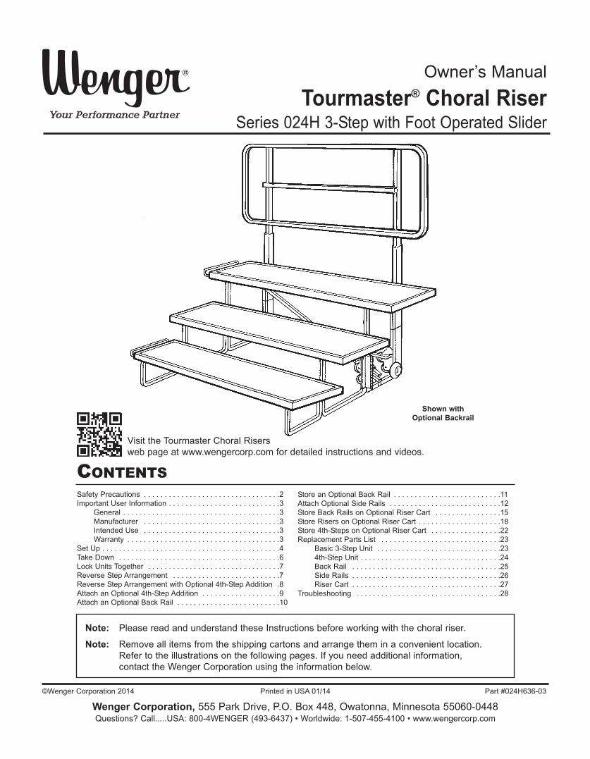
Owner’s Manual
Tourmaster® Choral RiserSeries 024H 3-Step with Foot Operated Slider
Note: Please read and understand these Instructions before working with the choral riser.
Note: Remove all items from the shipping cartons and arrange them in a convenient location. Refer to the illustrations on the following pages. If you need additional information, contact the Wenger Corporation using the information below.
CONTENTSSafety Precautions . . . . . . . . . . . . . . . . . . . . . . . . . . . . . . . . .2Important User Information . . . . . . . . . . . . . . . . . . . . . . . . . . .3
General . . . . . . . . . . . . . . . . . . . . . . . . . . . . . . . . . . . . . .3Manufacturer . . . . . . . . . . . . . . . . . . . . . . . . . . . . . . . . .3Intended Use . . . . . . . . . . . . . . . . . . . . . . . . . . . . . . . . .3Warranty . . . . . . . . . . . . . . . . . . . . . . . . . . . . . . . . . . . . .3
Set Up . . . . . . . . . . . . . . . . . . . . . . . . . . . . . . . . . . . . . . . . . . .4Take Down . . . . . . . . . . . . . . . . . . . . . . . . . . . . . . . . . . . . . . .6Lock Units Together . . . . . . . . . . . . . . . . . . . . . . . . . . . . . . . .7Reverse Step Arrangement . . . . . . . . . . . . . . . . . . . . . . . . . .7Reverse Step Arrangement with Optional 4th-Step Addition .8Attach an Optional 4th-Step Addition . . . . . . . . . . . . . . . . . . .9Attach an Optional Back Rail . . . . . . . . . . . . . . . . . . . . . . . . .10
Store an Optional Back Rail . . . . . . . . . . . . . . . . . . . . . . . . . .11Attach Optional Side Rails . . . . . . . . . . . . . . . . . . . . . . . . . . .12Store Back Rails on Optional Riser Cart . . . . . . . . . . . . . . . .15Store Risers on Optional Riser Cart . . . . . . . . . . . . . . . . . . . .18Store 4th-Steps on Optional Riser Cart . . . . . . . . . . . . . . . . .22Replacement Parts List . . . . . . . . . . . . . . . . . . . . . . . . . . . . .23
Basic 3-Step Unit . . . . . . . . . . . . . . . . . . . . . . . . . . . . . .234th-Step Unit . . . . . . . . . . . . . . . . . . . . . . . . . . . . . . . . . .24Back Rail . . . . . . . . . . . . . . . . . . . . . . . . . . . . . . . . . . . .25Side Rails . . . . . . . . . . . . . . . . . . . . . . . . . . . . . . . . . . . .26Riser Cart . . . . . . . . . . . . . . . . . . . . . . . . . . . . . . . . . . . .27
Troubleshooting . . . . . . . . . . . . . . . . . . . . . . . . . . . . . . . . . . .28
©Wenger Corporation 2014 Printed in USA 01/14 Part #024H636-03
Wenger Corporation, 555 Park Drive, P.O. Box 448, Owatonna, Minnesota 55060-0448Questions? Call.....USA: 800-4WENGER (493-6437) • Worldwide: 1-507-455-4100 • www.wengercorp.com
Visit the Tourmaster Choral Risers web page at www.wengercorp.com for detailed instructions and videos.
Shown with Optional Backrail

2
SAFETY PRECAUTIONS
Make sure that anyoneworking on the TourmasterChoral Riser has read andunderstands this manual.
! CAUTIONFailure to comply withWarnings and Cautions inthis document can result indamage to property orserious injury.
! CAUTION
Throughout this manual you will find cautions and warnings which are defined as follows.
• WARNING means that failure to follow the instruction may result in serious injury or death.• CAUTION means that failure to follow the instruction may result in serious injury or damage to
property.Read all of the safety instructions before assembling or using the Tourmaster Choral Riser.

3
IMPORTANT USER INFORMATIONGENERALCopyright © 2014 by Wenger Corporation
All rights reserved. No part of the contents of this manual may be reproduced, copied, or transmitted inany form or by any means including graphic, electronic, or mechanical methods or photocopying,recording, or information storage and retrieval systems without the written permission of the publisher,unless it is for the purchaser's personal use.
Printed and bound in the United States of America.
The information in this manual is subject to change without notice and does not represent a commitmenton the part of Wenger Corporation. Wenger Corporation does not assume any responsibility for anyerrors that may appear in this manual.
In no event will Wenger Corporation be liable for technical or editorial omissions made herein, nor fordirect, indirect, special, incidental, or consequential damages resulting from the use or defect of thismanual.
The information in this document is not intended to cover all possible conditions and situations that mightoccur. The end user must exercise caution and common sense when assembling or installing WengerCorporation products. If any questions or problems arise, call Wenger Corporation at 1-800-733-0393.
MANUFACTURERThe Tourmaster® Choral Riser 3-Step Model is manufactured by:
Wenger Corporation555 Park DriveOwatonna, MN 550601-507-455-4100 • 1-800-733-0393www.wengercorp.com
INTENDED USE• This product is designed to be an elevation step for vocal groups.• This product is intended for indoor use in normal ambient temperature and humidity conditions — it
must not be exposed to prolonged outside weather conditions.• This product is intended to be assembled only as described in these instructions.
WARRANTYThis product is guaranteed free of defects in materials and workmanship for fifteen full years from date of shipment. A full warranty statement is available upon request.
4
SET UP
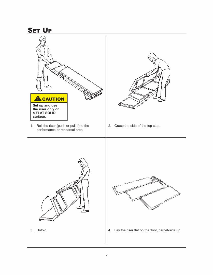
1. Roll the riser (push or pull it) to the performance or rehearsal area.
2. Grasp the side of the top step.
3. Unfold 4. Lay the riser flat on the floor, carpet-side up.
! CAUTIONSet up and use the riser only on a FLAT SOLID surface.

5
SET UP CONTINUED
5. Grasp the end of the top step at the “hand position” decals, and place your right foot on the riser leg decal.
6. Lift the riser toward you until you hear the latch pin snap twice. When lifting, keep your foot on the leg decal and lean back so your body weight helps pull up the riser.
IMPORTANT: The rear legs must be straight up and down, and the second lock must be engaged, or the riser is not fully latched.
7. To install a back rail, side rail or4th step unit, refer to theinstructions on pages 8 to 10.
! WARNINGTo avoid injury,grasp ends of topstep only at “handposition” decals.
! WARNINGRiser will fall iflatch pin is notproperly engaged.

6
TAKE DOWN1. Kick the latch release forward, and at the same time press down the latch lever with your foot.
2. Grasp the end of the top step at the “hand position” decals, and lower the unit flat on the floor.
! WARNINGDo not store riserunits standing onend.
! CAUTIONThe unit will drop tothe floor quickly.

7
LOCK UNITS TOGETHER
1. Before you lock any units together, set up all units and move them into position next to each other. To move a 3-Step Riser, lift the 1st step and roll the unit on its two positioning wheels.
With 3-Step Risers, also attach any Back Rails and 4th-Step options (see pages 10-11).
2. Lift one Riser, and place it over the unit-to-unit clamp on a second unit.
If the Riser hangs up on the clamp, loosen the clamp’s two capscrews. Adjust to fit, and retighten the capscrews.
1. Take off the first and third steps by loosening the capscrews that hold the steps to the legs. Don’t loosen the second steps capscrews yet.
2. Turn the first and third steps end-for-end, and switch their places as shown. Reattach the steps to the legs.
3. Remove the second step, turn it end-for-end, and reattach it to the legs.
4. Be sure all capscrews are tightened securely.
5. Remove the unit-to-unit clamps, and reattach them at the opposite end of the steps.
6. If a back rail is used on a reversed riser, reverse the rail loop also. To do this, depress the two snaps, separate the loop, turn the rail around, and snap it back together(see page 11).
REVERSE STEP ARRANGEMENT

8
1. Take off the first and fourth steps by loosening the capscrews that hold the steps to the legs. Don’t loosen the second or third steps capscrews yet.
2. Turn the first and fourth steps end-for-end, and switch their places as shown. Reattach the steps to the legs.
3. Remove the second and third steps. Turn them end-for-end, switch their places as shown, and reattach them to the legs.
4. Be sure all capscrews are tightened securely.
5. Remove the unit-to-unit clamps, and reattach them at the opposite end of the steps.
6. If a back rail is used on a reversed riser, reverse the rail loop also. To do this, depress the two snaps, separate the loop, turn the rail around, and snap it back together(see page 11).
REVERSE STEP ARRANGEMENT WITHOPTIONAL 4TH-STEP ADDITION

9
ATTACH AN OPTIONAL 4TH-STEP ADDITION
1. If the riser has a Back Rail installed, remove it before attaching the 4th step.
2. Open both locking clamps on the 4th step.
3. Position the 4th steps brace brackets to the right side (viewed from the rear) of the risers leg assemblies. On the right side, place the bracket between the leg and the positioning wheel.
4. Lean the 4th step to the left, and slip its leg support brackets over the riser leg assemblies.
5. Push the locking clamps down so that they cover both leg assemblies on the riser.
! WARNINGRiser is unsafeunless both clampsare fully locked.

NOTE: Back Rails (optional) are recommendedon all risers.
1. Open the locking clamps on the lower posts of the Back Rail.
NOTE: In the following steps, install the lower posts so their wheels areon the inside (facing each other).
2. Riser without a 4th Step. Set a lower post on the floor, and hook its bracket around the riser leg.
Riser with a 4th Step. Set a lower post on the 4th-Step cross tube, and hook its bracket around the riser leg.
3. Push the locking clamp down until it secures the post to the riser leg.
4. Attach the other post in the same way.
5. To install the rail, slide the upper posts into the lower posts until the lock buttons snap into place.
! WARNINGRiser is unsafeunless both clampsare fully locked.
Hook bracketaround leg,then pushclamp down.
10
ATTACH AN OPTIONAL BACK RAIL

1. Open the locking clamps, and move the Back Rail away from the riser.
For storage, turn the rail 90° and lean it against the wall (setting on its side).
2. (Optional — provides more compact storage)Press the snap buttons and remove the lower posts from the rail.
For transport and storage, attach the lower posts to the rail cross brace (in the same way that they were attached to the riser legs).
11
STORE AN OPTIONAL BACK RAIL

Note: Back Rails are required in order to attach Side Rails.
1. Place the Side Rail in the approximate attachment position with the leg extension resting on thefloor. Slide the Side Rail towards the Back Rail until the Side Rail Bracket fits over the Back Railas shown below.
Back Rail
Side Rail
Side Rail
Back Rail
Side Rail Bracket
Swing Bracket
Leg Extension
12
ATTACH OPTIONAL SIDE RAILS

13
ATTACH OPTIONAL SIDE RAILS CONTINUED
2. Rotate the Upper and Lower Swing Bracketsto a vertical position, locking the Side Rail tothe Back Rail.
Back Rail
Side Rail
Lower Swing Bracket
3. Lift and hold the front of the riser off the floorand slide the Lower Leg Cradle Bracket underthe Step Support Frame. Lower the Front Riserplacing the Step Support Frame into the LowerLeg Cradle Bracket.
Front Riser
Lower Leg CradleBracket
Step Support Frame
! CAUTIONTwo people arerequired to performthis step.
Lift the front of the Riser slightly offof the floor and slide the LowerLeg Cradle Bracket under the StepSupport Frame. Lower the Frameinto the Cradle.
Upper SwingBracket

14
ATTACH OPTIONAL SIDE RAILS CONTINUED
4. A Rail Lock Down Bracket is used to reduce movement of the Back Rail when using the SideRail. Thread the Right and Left Hooks into the Turnbuckle. Engage the Back Rail and Top Stepwith the Rail Lock Down Bracket Hooks as shown below. Tighten the Rail Lock Down Bracket byturning the Turnbuckle clockwise.
Back Rail
Top Step
Rail Lock Down Bracket
Turnbuckle
Left Hand Hook
Right Hand Hook
Back Rail
Engage the Hook withthe Top Step
Place the Hook overthe Back Rail

15
STORE BACK RAILS ON OPTIONAL RISER CARTLoad up to four Back Rails onto a Riser Cart as follows. 1. Lift a Back Rail with the Positioning Wheels on the legs pointing upward and the legs next to the
Cart (Horizontal Rail is away from the Cart).2. Place the Back Rail onto the Back Rail Supports with each Back Rail Leg facing toward the
Back Rail Support Posts as shown below.
Back Rail
Back Rail Leg
Back Rail Support
Back Rail Leg Positioning Wheel
Back Rail Support Post
Riser Cart
Back Rail Support
Back Rail Support Post
Back Rail Leg
Place the Back Rail Legs outsideof the Back Rail Support Post
Riser Cart with one BackRail Loaded
Horizontal Rail

16
STORE BACK RAILS ON OPTIONAL RISER CARTCONTINUED
3. To load the second Back Rail, lift it with the Positioning Wheels on the legs pointing upward andthe Back Rail Legs facing away from the Cart.
4. Place the Back Rail onto the Back Rail Supports with the Back Rail Horizontal Rails touching asshown below.
Note: Each pair of Back Rails can be loaded onto the Cart with either the Horizontal Rail touchingor the Back Rail Legs nested together.
First Back Rail
Second Back Rail
Riser Cart
Back Rail Support
Back Rail Support Post
First Back Rail Leg
Second Back Rail Leg
Back Rail Legs
Note that the Back Rail Legs are on oppositesides of the Back Rail Horizontal Members andthe Horizontal Rails are touching.
Positioning Wheels
Horizontal Rails

17
5. Place the third and fourth Back Rails onto the Cart with the Horizontal Rails touching as shownbelow.
Third Back Rail
Fourth Back Rail
Horizontal Rails
Horizontal Rails are touchingand the Vertical Legs of theSecond and Third Back Railsnest together.
Second Back Rail
Vertical Legs
Cart loaded withtour Back Rails
Third Back Rail
Riser Cart
Horizontal Rails
STORE BACK RAILS ON OPTIONAL RISER CARTCONTINUED

18
STORE RISERS ON OPTIONAL RISER CARTLoad up to four Risers onto the Riser Cart as follows.1. Begin opening the Swing Arms by pushing upward on the under side of the Swing Arm
Horizontal Bar as close to the Swing Arm Post as possible. Always start with the highest Armand swing the Arm away from the Cart.
Swing ArmHorizontal Bar
Riser Cart
2. Continue opening all of the Swing Arms
Swing Arm
Swing Arm Pivot Post Lift the Swing Arm hereto free the keeper on theend of the Arm to allowswinging.
Keeper
Cart Support Frame
Loaded Back Rails are notshown for clarity.
Riser Cart
Swing Arm Post

19
STORE RISERS ON OPTIONAL RISER CART CONTINUED
3. With two people working together, place the first Riser onto the Cart. The Positioning Wheelswill hang over the right end of the Cart Support Frame.
Note: The 13-inch Swing Arm must be on the right side of the Cart. If the 13-inch Swing Arm is noton the right side of the Cart, it is assembled incorrectly. Call Customer Service forassistance in the correct assembly.
Folded Riser
Riser Positioning WheelsRiser is placed with Positioning Wheels hangingover the right end of the Support Frame
4. Close the two lower Swing Arms. It will be necessary to lift all of the Arms high enough for thetwo lower Arms to clear the Riser.
Note: When the Swing Arm Keeper is inserted into the Holding Socket, a dangerous pinch pointdevelops. Serious injury is possible if this precaution is not observed.
! WARNINGA Dangerous PinchPoint developswhen the SwingArm closes.
Swing Arms shown in theclosed position.
Back Rails are notshown for clarity ! CAUTION
Always startloading Risers atthe bottom of theRiser Cart.
Riser Cart
Folded Riser
Positioning Wheels musthang outside of the Cart.
! CAUTIONAlways use twopeople to loadrisers

20
STORE RISERS ON OPTIONAL RISER CART CONTINUED
5. With two people working together, place the second Riser onto the Cart with the positioningWheels on the left end, opposite from the first Riser Positioning Wheels. Make sure that thePositioning Wheels hang outside of the Swing Arm.
Second Folded Riser
Riser Positioning Wheels
! WARNINGA Dangerous PinchPoint developswhen the SwingArm closes.
6. Close the two Swing Arms above the Riser. It will be necessary to lift all of the Arms highenough for the two Arms to clear the Riser.
Note: When the Swing Arm closes, a dangerous pinch point develops. Serious injury is possible ifthis precaution is not observed.
Swing Arm Closed
Swing Arm Closed
Second set of Swing Armsshown in the closed
position.
First Riser
Second Riser
Riser Cart

21
STORE RISERS ON OPTIONAL RISER CART CONTINUED
7. With two people working together, place the third and fourth Risers onto the Cart (as in steps 2to 6 above) with the Positioning Wheels alternating as shown below. Make sure that thePositioning Wheels hang outside of the Swing Arm.
Note: If the Riser Cart is to be transported by a vehicle, always fasten each Riser to both SwingArms (or Riser Cart Frame for the lowest Riser) with rubber or polyurethane tie down cordsor light duty cinch straps.
! WARNINGA Dangerous PinchPoint developswhen the SwingArm closes.
Fourth Riser
Third Riser
! CAUTIONTwo people arealways required tomove the loadedCart.
Riser Cart
Riser Positioning Wheels
Riser Positioning Wheels
22
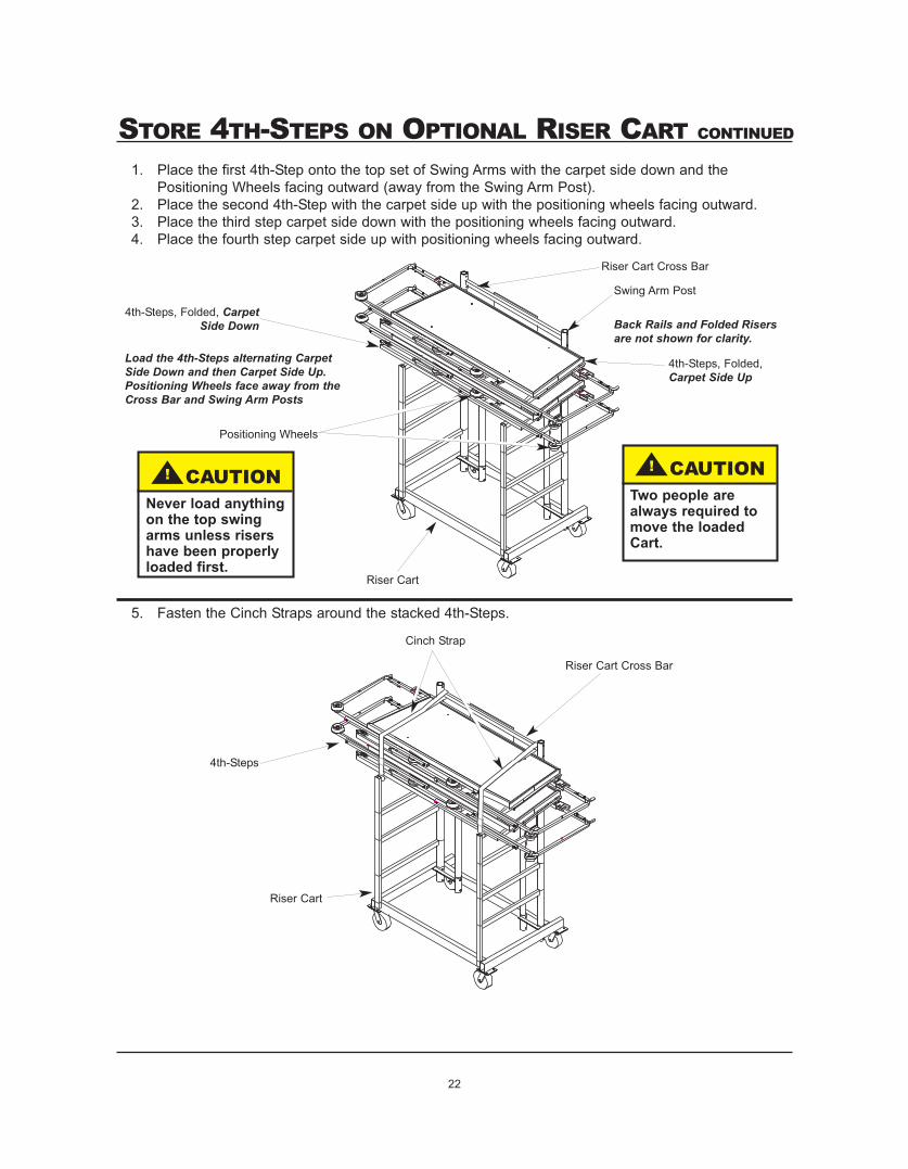
STORE 4TH-STEPS ON OPTIONAL RISER CART CONTINUED
1. Place the first 4th-Step onto the top set of Swing Arms with the carpet side down and thePositioning Wheels facing outward (away from the Swing Arm Post).
2. Place the second 4th-Step with the carpet side up with the positioning wheels facing outward.3. Place the third step carpet side down with the positioning wheels facing outward.4. Place the fourth step carpet side up with positioning wheels facing outward.
Riser Cart
Swing Arm Post
4th-Steps, Folded, CarpetSide Down
Positioning Wheels
5. Fasten the Cinch Straps around the stacked 4th-Steps.
Back Rails and Folded Risersare not shown for clarity.
Riser Cart
Cinch Strap
Riser Cart Cross Bar
4th-Steps
Load the 4th-Steps alternating CarpetSide Down and then Carpet Side Up.Positioning Wheels face away from theCross Bar and Swing Arm Posts
Riser Cart Cross Bar
! CAUTIONTwo people arealways required tomove the loadedCart.
! CAUTIONNever load anythingon the top swingarms unless risershave been properlyloaded first.
4th-Steps, Folded,Carpet Side Up
23
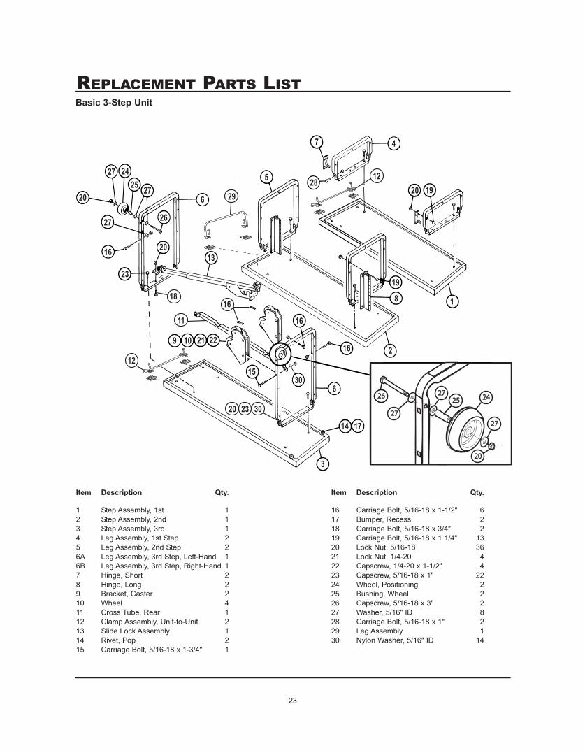
REPLACEMENT PARTS LISTBasic 3-Step Unit
1 Step Assembly, 1st 12 Step Assembly, 2nd 13 Step Assembly, 3rd 14 Leg Assembly, 1st Step 25 Leg Assembly, 2nd Step 26A Leg Assembly, 3rd Step, Left-Hand 16B Leg Assembly, 3rd Step, Right-Hand 17 Hinge, Short 28 Hinge, Long 29 Bracket, Caster 210 Wheel 411 Cross Tube, Rear 112 Clamp Assembly, Unit-to-Unit 213 Slide Lock Assembly 114 Rivet, Pop 215 Carriage Bolt, 5/16-18 x 1-3/4" 1
16 Carriage Bolt, 5/16-18 x 1-1/2" 617 Bumper, Recess 218 Carriage Bolt, 5/16-18 x 3/4" 219 Carriage Bolt, 5/16-18 x 1 1/4" 1320 Lock Nut, 5/16-18 3621 Lock Nut, 1/4-20 422 Capscrew, 1/4-20 x 1-1/2" 423 Capscrew, 5/16-18 x 1" 2224 Wheel, Positioning 225 Bushing, Wheel 226 Capscrew, 5/16-18 x 3" 227 Washer, 5/16" ID 828 Carriage Bolt, 5/16-18 x 1" 229 Leg Assembly 130 Nylon Washer, 5/16" ID 14
276
26
2013
27
27
20
2425
16
23
18
11
9 10 21 22
16
1530
16
6
14 17
3
7
28
4
20 19
19
8
2
1
5 12
12
29
16
2626
2727
272725252626
2727
2020
2424
20 23 30
Item Description Qty. Item Description Qty.
24
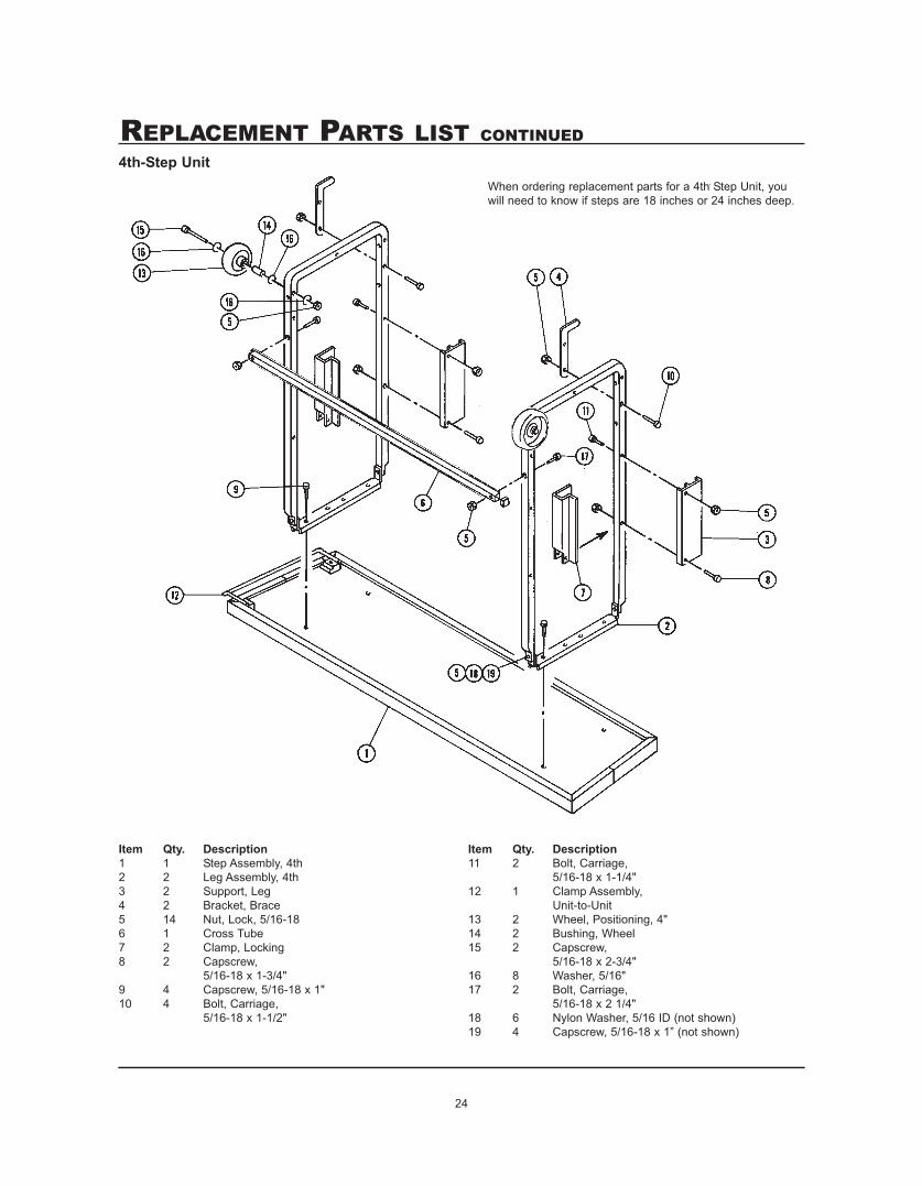
REPLACEMENT PARTS LIST CONTINUED
Item Qty. Description1 1 Step Assembly, 4th2 2 Leg Assembly, 4th3 2 Support, Leg4 2 Bracket, Brace5 14 Nut, Lock, 5/16-186 1 Cross Tube7 2 Clamp, Locking8 2 Capscrew,
5/16-18 x 1-3/4"9 4 Capscrew, 5/16-18 x 1"10 4 Bolt, Carriage,
5/16-18 x 1-1/2"
Item Qty. Description11 2 Bolt, Carriage,
5/16-18 x 1-1/4"12 1 Clamp Assembly,
Unit-to-Unit13 2 Wheel, Positioning, 4"14 2 Bushing, Wheel15 2 Capscrew,
5/16-18 x 2-3/4"16 8 Washer, 5/16"17 2 Bolt, Carriage,
5/16-18 x 2 1/4"18 6 Nylon Washer, 5/16 ID (not shown)19 4 Capscrew, 5/16-18 x 1” (not shown)
When ordering replacement parts for a 4th Step Unit, youwill need to know if steps are 18 inches or 24 inches deep.
4th-Step Unit

25
REPLACEMENT PARTS LIST CONTINUED
Item Qty. Description1 2 Post, Lower2 1 Rail Assembly3 2 Bracket, Back Rail4 2 Clamp, Locking5 2 Plug, Rectangular6 6 Washer, Flat, 5/16"7 4 Nut, Lock, 5/16-18 x 1-3/4"8 2 Capscrew, 5/16-18 x 1-3/4"9 2 Plug, Square10 2 Wheel, Positioning, 2"11 2 Nut, 5/16-1812 2 Capscrew, 5/16-18 x 2-1/4"
Back Rail

26
REPLACEMENT PARTS LIST CONTINUED
Item Qty* Description1 2 Side Rail Bracket2 4 Capscrew, 5/16-18x2”3 4 Swing Bracket4 4 Flat Washer, 5/16”5 10 Locknut, 5/16-186 2 Side Rail7 6 Capscrew, 5/16-18x1-3/4”8 2 Side Rail Leg9 2 Plug, Square, 1-1/4”
10 2 Slide Leg* Quantity is for a set of Side Rails.
Side Rails

27
REPLACEMENT PARTS LIST CONTINUED
Item Qty Description1 12 Hex Head Cap Screw, 3/8-16x2-1/2"2 16 Hex Head Cap Screw, 3/8-16x1"3 28 Hex Head Lock Nut, 3/8-164 1 Cross Bar5 2 Swing Arm Post6 4 Swing Arm, 13-inch7 4 Swing Arm, 10-inch8 1 Riser Cart Frame9 4 Caster
10 2 Back Rail Support Post11 2 Safety Strap (not shown)
Riser Cart
28
Stiff Operation (hard to set up or take down)Spray the pivot points and slide with a nonstaining lubricant like WD-40.
Carpet “Balls Up”Normal with a new carpet. Vacuum periodically.
Wheel Doesn’t Turn FreelyLoosen the bolt just enough for free turning.
Riser “Rattles” When Set UpCheck for loose fasteners.
Rubber Wheel Not RoundDon’t stack stored units more than three high, and don’t place other weights on top - or thewheels may form flat spots.
Units Won’t Hook TogetherUnit-to-unit clamps out of position. Loosen the screws and readjust the clamps.
TROUBLESHOOTING