totalpac 3 - fireflex
TRANSCRIPT

FM-076A-0-6A
Advanced Integrated Fire Protection System
TOTALPAC ®3
Owner's Operation and
Maintenance Manual
DOUBLE INTERLOCK PREACTION SYSTEM ELECTRIC / PNEUMATIC RELEASE

Page ii TOTALPAC ®3
Integrated Fire Protection System OWNER'S OPERATION & MAINTENANCE MANUAL
FM-076A-0-6A
Copyright © 2020 FIREFLEX Systems Inc.
All Rights Reserved
Reproduction or use, without express written permission from FIREFLEX Systems Inc, of any portion of this manual is prohibited. While all reasonable efforts have been taken in the preparation of this manual to assure its accuracy, FIREFLEX Systems Inc assumes no liability resulting from any errors or omissions in this manual, or from the use of the information contained herein. TOTALPAC ® is a registered trademark of FIREFLEX Systems Inc.
FIREFLEX Systems Inc. reserves the right to make changes to this manual and the data sheets herewith at any time, without prior notification.

TOTALPAC ®3 Page iii
Integrated Fire Protection System OWNER'S OPERATION & MAINTENANCE MANUAL
FM-076A-0-6A
Table of Contents Double Interlock Preaction System - Electric / Pneumatic Release
General Section .......................................................................................................... Section A 1- General description 2- Listings and approvals 3- Applicable standards 4- Environment 5- Features 6- Configuration description 7- System release
Mechanical Section ...................................................................................................................... Section B 1- Installation, operation & maintenance instructions
1.1 Installation 1.2 Preliminary inspection before placing the system in service 1.3 Placing the system in service 1.4 System operation 1.5 Emergency instructions 1.6 Placing the system back in service after operation 1.7 Inspections & tests 1.8 Maintenance
2- System trim 2.1 Normal condition
Trim Options ................................................................................................................................. Section C 1- Shut-off valve & sight glass 2- Fire department connection 3- Semi and full flanged option 4- Anti-column device option 5- OSHPD seismic option
Air Supply ..................................................................................................................................... Section D 1- Cabinet air supplies 2- Operation 3- Maintenance and inspection 4- Air supply options
Control Section .............................................................................................................................Section E 1- Self-contained unit with integrated release control panel
1.1 Product description 1.2 Self-contained unit with Viking VFR-400 release control panel 1.3 Technical data 1.4 Visual indicators 1.5 Control buttons 1.6 Time & date setting
2- Remotely controlled unit without release control panel 2.1 Product description 2.2 Technical data

Page iv TOTALPAC ®3
Integrated Fire Protection System OWNER'S OPERATION & MAINTENANCE MANUAL
FM-076A-0-6A
Electrical Section .......................................................................................................................... Section F 1- Self-contained configurations 2- Optional modules 3- Remotely controlled configuration
Dimensional Data & Cabinet ....................................................................................................... Section G 1- Cabinet unit 2- Skid mounted unit
Limited Warranty .......................................................................................................................... Section H

TOTALPAC®3 Page 1 of 2
Integrated Fire Protection System AGeneral Section - Double Interlock Preaction System - Electric/Pneumatic Release
FM-076A-0-26A
1- General description
This TOTALPAC ®3 integrated fire protection system byFIREFLEX Systems Inc. consists of a preaction system trimtotally pre-assembled, pre-wired and factory tested. Allelectrical and mechanical components of the system arecontained in one single unit.
Note: Skid units include the trim components only and mustbe wired by the installing contractor.
The only connections required for installation are the watersupply inlet, the water discharge outlet, the main drain, thedetection network, the electrical trouble, supervisory andalarm connections, as well as the AC power lines for therelease control panel and optional air compressor. Thedischarge outlet is connected to a fixed piping network ofautomatic sprinklers. Water is the extinguishing agent.On system piping network, closed heat sensitive automaticsprinklers are spaced and located in accordance withrecognized installation standards in order to detect a fire.Only those sprinklers immediately over or near to fireoperate, minimizing water damage.Double interlock preaction system with electric/pneumaticrelease uses closed automatic sprinklers on the systempiping network, which is supervised with air pressure. Thedetection network is installed in parallel with the systempiping network and is designed to operate before anautomatic sprinkler fuses from the system piping network.Detection system operates first and gives a supervisorysignal.Double interlock preaction system is designed so thedeluge valve will open when both detector on detectionnetwork activates and a loss of pressure in the systempiping network occurs. When the deluge valve opens,water will flow into the system piping network and out ofany open automatic sprinklers and other opening on thesystem piping network.Under normal supervisory condition, a loss of pressurealone in the system piping network will only give asupervisory signal.
Note: Every TOTALPAC ®3 unit is identified with its uniqueserial number. This number is located on an adhesivelabel inside the main door panel and is used to maintain arecord in our computerized data base. Have this serialnumber handy when calling for information on your unit(format is TOT3#### or TOTS#### for skid units).
2- Listings and approvalsIn addition to being fabricated under tight ISO-9001manufacturing and quality control procedures, yourTOTALPAC ®3 unit has also been tested and approved byrecognized laboratories.
Here is the list of Listings & Approvals it meets:- Underwriters Laboratories Inc. (UL): Preaction
TOTALPAC ®3 systems are UL Listed under "SpecialSystem Water Control Valves - Assembled Units,category # VKYL.EX4641" and "Assembled UnitsCertified for Canada, Category # VKYL7.EX4641 (c-UL)".
- Factory Mutual Research <FM>: Preaction TOTALPAC ®3systems are FM Approved under the heading: "AutomaticWater Control Valves" when installed with specificcomponents.
- OSHPD pre-approval OSP-0341-10 (optional).
WARNING Any unauthorized modification or addition madeon-site to a factory built Listed unit will void this Listing.Such modifications or additions may void the unit'swarranty as well. Consult your nearest FIREFLEX Systemsauthorized distributor before proceeding with suchmodifications or additions.
3- Applicable standardsThe TOTALPAC ®3 complies with the following standards:
- NFPA-13 Sprinkler Systems- NFPA-15 Water Spray Fixed Systems- NFPA-16 Foam-Water Sprinkler and Foam-Water Spray
Systems- NFPA-72 Fire Alarm SystemsBefore installation, the contractor installing the unit shallalso be familiar with the following documents andstandards:
- Applicable Local & State Building Codes- Any additional requirements of the Local Authority Having
Jurisdiction
4- EnvironmentTOTALPAC ®3 unit shall be installed in a dry and cleanlocation. Verify that all equipment is properly heated andprotected to prevent freezing and physical damage. Referto section E CONTROL SECTION for environment data.The unit and its components must be kept free of foreignmatter, freezing conditions, corrosive atmospheres,contaminated water supplies, and any condition that couldimpair its operation or damage the components.The frequency of the inspections and maintenance willvary depending on these environmental conditions as wellas the condition of the air supply to the system. The owneris responsible for maintaining the fire protection systemand devices in proper operating condition. Refer tosection B MECHANICAL SECTION for maintenanceinstructions.
Page 2 of 2 TOTALPAC ®3
A Integrated Fire Protection System
General Section - Double Interlock Preaction System - Electric/Pneumatic Release
FM-076A-0-26A
5- Features
The TOTALPAC ®3 unit is superior to many other products which are actually available on the fire protection market. It is manufactured by FIREFLEX Systems Inc. which has developed and introduced the concept of integrated fire protection systems.
Main features are:
Trouble free design for safe and easy application
Available in 6 sizes from 1½" (40 mm) to 8" (200 mm) diameter
Uses the Viking deluge valve
Unit is available either with or without integrated release control panel
Skid version available
Compact, aesthetic and easy to move
User-friendly standardized owner's manual with every unit
Unique serial number on every unit
Uses only c-UL-us Listed and FM Approved components
Designed in accordance with NFPA Standards
Trim is fully assembled and tested at the factory
All trims are galvanized steel, Listed and Approved for 250 PSI (1724 kPa) service maximum
Quick connections to water supply and drain on both sides, and sprinkler riser on top of unit, all available with grooved end or flanged fittings
No open drain cup inside unit
Sturdy 14 gauge steel cabinet or skid, painted fire red with oven baked polyester powder on phosphate base
Textured rust proof finish
Neoprene gasket on all doors to eliminate vibrations
Separate unlocked access hatch to emergency manual release
Key-alike locks on all cabinet doors
Manufactured under ISO-9001 quality control procedures.
6- Configuration description
TOTALPAC ®3 preaction system is built around the Viking trim using straight through deluge valve model F-1 (model F-2 is the Halar ® coated version for use in corrosive environments).
The valve is rated up to a maximum of 250 PSI WWP (1724 kPa) and is available in the following diameters:
1½" (40 mm) 3" (80 mm) 6" (150 mm)
2" (50 mm) 4" (100 mm) 8" (200 mm)
TOTALPAC ®3 preaction system is supplied with groove/ groove deluge valve. Unit with flange/flange deluge valve is also available on request.
6.1 Double interlock preaction system
The system piping network is pressurized with air or nitrogen gas. The preaction system uses the Viking deluge valve which opens when both the detection network activates and a loss of pressure in the system piping network occurs, or anytime the handle of the emergency release valve is pulled.
If the detection network activates due to fire or malfunction, the deluge valve will not open.
If the system piping network is broken or an automatic sprinkler fuses, the deluge valve will not open.
7- System release
7.1 Electric/pneumatic release
Preaction system with electric/pneumatic release requires an electric detection network equipped with compatible detectors. Release trim for the deluge valve requires a normally closed solenoid valve controlled by an approved releasing control panel (if provided with this system, see section E CONTROLS SECTION and VFR-400 manual for details). Release trim for the deluge valve also use a pneumatic actuator which is held closed by the pressure maintained in the system piping network. The detection network must activate and the pressure must be released from the system piping network in order to open the deluge valve.
In fire condition, both the activation of a detector on the detection network and the fusing of an automatic sprinkler from the system piping network are required to energize the normally closed solenoid valve and to release the pneumatic actuator, causing the deluge valve to open. Water will flow from the preaction system through opened sprinklers. Automatic sprinkler must open to allow water to flow from the preaction system.

TOTALPAC ®3 Page 1 of 8
Integrated Fire Protection System B Mechanical Section - Double Interlock Preaction System - Electric/Pneumatic Release
FM-076A-0-46A
1- Installation, operation & maintenance instructions
Note: Numbers indicated between brackets refer to figure 1 DETAILED SYSTEM TRIM SCHEMATICS from this section and section D AIR SUPPLY.
1.1 Installation
1. Conform to local municipal or other codes regarding installations of fire protection systems.
2. Install the TOTALPAC ®3 unit and connect the system according to instruction manual and technical data supplied.
IMPORTANT ! The cabinet must be firmly anchored to the floor using all four (4) anchoring holes (see section G CABINET).
Note: The drain collector shall be connected to an open drain. Do not restrict or reduce drain piping.
3. Install the system piping network in accordance with applicable standards.
4. Connect supervisory and alarm signals according to electrical schematics and if applicable, all detection and signaling circuits (see section F ELECTRICAL).
5. If applicable, connect the AC power to the release control panel and to the air compressor, each on a separate breaker in the electric distribution panel (see section F ELECTRICAL).
Notes: AC power connections must be made by a qualified installer according to national standards and equipment specifications.
Do not apply AC power to the equipment yet.
6. Perform preliminary inspection prior to put system in service (see paragraph 1.2 of the current section).
7. Place the system in service (see paragraph 1.3 of the current section).
8. Perform the annual inspection sequence (see paragraph 1.8 of the current section) and test each detection device and alarm unit.
9. If the system does not operate as it should, make the necessary corrections according to manuals issued or consult your distributor or FIREFLEX Systems Inc.
10. Make sure that building owner or a delegated representative has received instructions regarding the operation of the system.
WARNING ! TOTALPAC ®3 unit must be installed in an area not subject to freezing temperatures or physical damage.
1.2 Preliminary inspection before placing the system in service
1. Open door to mechanical section.
a) Main water supply valve (D1) must be CLOSED.
b) Priming valve (B1) must be CLOSED.
c) Air supply for system piping network must be CLOSED (see section D AIR SUPPLY).
d) Flow test valve (B6) and main drain valve (D3) must be CLOSED.
e) Alarm test valve (B5) must be CLOSED.
f) Gauges (B11, B12 and E3) should show 0 PSI (0 kPa).
g) If applicable, the shut-off valve (D4) must be OPEN.
2. OPEN the manual emergency release valve (B10) and make sure the deluge valve (A1) is tripped.
3. Using the built-in contractor's hydrostatic test ports (see figure 1 of this section and section D AIR SUPPLY), fill system piping network with water and maintain pressure as per NFPA-13 requirements.
WARNING ! Do not subject the pressure gauges and pressure transducer to hydrostatic pressure above 250 PSI (1724 kPA). Close gauge valves before proceeding with hydrostatic test.
4. Correct leaks if any before completing test.
5. Verify that main water supply valve (D1) is still CLOSED.
6. OPEN main drain valve (D3) to completely drain the system piping network.
7. If applicable, apply AC power to the release control panel and the air compressor. The air supply must be CLOSED (see section D AIR SUPPLY).
8. If applicable, connect the batteries to the release control panel. Observe battery size and polarity.
For battery capacity calculations, see the VIKING VFR-400 INSTALLATION, OPERATION AND INSTRUCTION MANUAL provided with the TOTALPAC ®3 unit.
Note: Batteries shall be installed with the release control panel at hanged position. Battery compartment should always stay closed while rotating the release control panel.
9. Reset the release control panel and silence the alarms (see section E CONTROLS).

Page 2 of 8 TOTALPAC ®3
B Integrated Fire Protection System
Mechanical Section - Double Interlock Preaction System - Electric/Pneumatic Release
FM-076A-0-46A
1.3 Placing the system in service
1. Verify that the main water supply valve (D1) is CLOSED. Verify that the system has been properly drained.
2. Verify that all automatic sprinklers are set and that inspector's test valve and/or piping auxiliary drain valves are CLOSED.
3. CLOSE main drain valve (D3). Verify that the manual emergency release valve (B10) is CLOSED.
4. Air supply must be OPEN (see section D AIR SUPPLY).
5. Establish recommended supervisory pressure to the system piping network (see paragraph 2.1 NORMAL CONDITION of the current section and section D AIR SUPPLY).
Note: On system provided with air pressure maintenance device (air supply style "B"), verify that the APMD bypass valve (E8) is CLOSED and that APMD input and output valves (E6 and E7) are OPEN.
6. OPEN priming valve (B1). Verify that the pressure indicated at the priming pressure gauge (B11) is equal to, or greater than the pressure indicated at the water supply pressure gauge (B12).
7. Reset the release control panel (see section E CONTROLS). Solenoid valve (F1) should CLOSE.
8. OPEN flow test valve (B6). PARTIALLY OPEN main water supply valve (D1).
9. When full flow develops from the flow test valve (B6), CLOSE the flow test valve. Verify there is no flow from drip check valve (B7) when the plunger is pushed.
10. FULLY OPEN the main water supply valve (D1).
11. Verify that the alarm test valve (B5) is CLOSED and that all other valves are in their "normal" operating position (see paragraph 2.1 NORMAL CONDITION of the current section).
12. Reset the release control panel (see section E CONTROLS).
13. Check and repair all leaks.
14. On new installation, system that has been placed out of service, or where new equipment has been installed, trip test the system to verify that all equipment functions properly (see paragraph 1.7.2 FULL FLOW TRIP TEST of the current section).
15. Notify the AUTHORITY HAVING JURISDICTION, remote station alarm monitors, and those in the affected area that the system is in service.
Note: When a valve has been removed from service and is subject to freezing or will be out of service for an extended period of time, all water must be removed from the priming chamber, trim piping, water supply piping and any other trapped areas.
1.4 System Operation
1.4.1 In the SET condition
System water supply pressure enters the priming chamber of the deluge valve (A1) through the priming line which includes a normally open priming valve (B1), strainer (B2), restricted orifice (B3) and spring loaded check valve (B4).
Water pressure is trapped in the priming chamber of the deluge valve (A1) by a spring loaded check valve (B4), pneumatic actuator (F3), normally closed solenoid valve (F1), PORV (B9) (pressure operated relief valve) and manual emergency release valve (B10). The pressure in the priming chamber holds the deluge valve clapper closed, keeping the outlet chamber and system piping dry.
1.4.2 In a fire condition
When the detection condition is satisfied, the release control panel energizes the solenoid valve (F1). Alarms activates but the deluge valve (A1) will not open. When an automatic sprinkler fuses, the low air pressure switch (F4) activates, and the pneumatic actuator (F3) opens. Both conditions are required to open the deluge valve (A1).
Pressure from the priming chamber of the deluge valve (A1) is released to the open drain manifold faster than it is supplied through the restricted orifice (B3). The deluge valve clapper opens to allow water to flow into the piping network and alarm devices, causing water flow alarms connected to the alarm pressure switch (C1) and the optional water motor alarm (C2) to activate. When an automatic sprinkler fuses, water will flow from the system piping network.
When the deluge valve (A1) opens, the sensing end of the PORV (B9) is pressurized, causing it to open. It then continually vent the priming chamber, preventing the closure of the deluge valve. The deluge valve can only be reset after the system is taken out of service.
Note: If the detection system operates due to mechanical damage or malfunction, the deluge valve (A1) will stay closed.
1.4.3 Manual operation
Anytime the handle of the manual emergency release valve (B10) is triggered, pressure is released from the priming chamber of the deluge valve (A1) causing deluge valve to open. Water will flow into the system piping network and alarm devices (C1 and optional C2) will operate. The PORV (B9) keeps the deluge valve open. When an automatic sprinkler fuses, water will flow from the system piping network.
1.4.4 Supervisory condition
If an automatic sprinkler opens prior the operation of the detection system or any time the supervisory pressure is lost in the system piping network, the low air pressure switch (E4) will give a low air supervisory signal, but the deluge valve (A1) will stay closed.

TOTALPAC ®3 Page 3 of 8
Integrated Fire Protection System B Mechanical Section - Double Interlock Preaction System - Electric/Pneumatic Release
FM-076A-0-46A
1.5 Emergency instructions
To take system out of service
WARNING ! Placing a control valve or detection system out of service may eliminate the fire protection capabilities of the system. Prior to proceeding, notify all local AUTHORITIES HAVING JURISDICTION. Consideration should be given to employ a fire patrol in the affected areas.
After a fire, verify that the fire is OUT and that placing the system out of service has been authorized by the appropriate local AUTHORITY HAVING JURISDICTION.
Sprinklers piping that have been subjected to a fire must be returned to service as soon as possible. The entire system must be inspected for damage, and repaired or replaced as necessary.
1. CLOSE main water supply valve (D1).
2. OPEN main drain valve (D3).
3. If applicable, silence audible devices (see section E CONTROLS).
Note: Electric alarms controlled by a pressure switch installed at the ¾"-NPT (20mm) connection (C2) for a non-interruptible alarm signal cannot be shut-off until the deluge valve (A1) is reset or taken out of service.
4. Air supply must be CLOSED (see section D AIR SUPPLY).
5. OPEN flow test valve (B6).
6. CLOSE priming valve (B1).
7. Replace any detector that have been damaged.
8. Replace any automatic sprinkler that have opened, been damaged or exposed to fire conditions.
9. Return the system to service as soon as possible (see paragraph 1.6 PLACING THE SYSTEM BACK IN SERVICE AFTER OPERATION of the current section).
10. Perform all recommended maintenance procedures (see paragraph 1.8 MAINTENANCE in the current section).
Note: When a system has been removed from service and is subject to freezing or will be out of service for an extended period of time, all water must be removed from the priming chamber, trim piping, water supply piping and any other trapped areas.
1.6 Placing the system back in service after operation
1. Verify that the system has been properly drained. Verify that all automatic sprinklers are set and/or inspector's test valve and system piping auxiliary drain valves are CLOSED.
2. Verify that the main water supply valve (D1) is CLOSED, and that the manual emergency release valve (B10) is CLOSED. CLOSE main drain valve (D3).
3. Air supply must be OPEN (see section D AIR SUPPLY).
4. Restore supervisory pressure to the system piping network (see section D AIR SUPPLY).
Note: On system provided with air pressure maintenance device (air supply style "B"), verify that the APMD bypass valve (E8) is CLOSED and that APMD input and output valves (E6 and E7) are OPEN.
5. OPEN priming valve (B1). Verify that the pressure indicated at the priming pressure gauge (B11) is equal to, or greater than the pressure indicated at the water supply pressure gauge (B12).
6. Reset the release control panel (see section E CONTROLS). Solenoid valve (F1) should CLOSE.
7. OPEN flow test valve (B6). PARTIALLY OPEN main water supply valve (D1).
Note: Do not open main water supply valve (D1) until gauge (B11) shows stabilized pressure.
8. When full flow develops from the flow test valve (B6), CLOSE the flow test valve. Verify there is no flow from drip check valve (B7) when the plunger is pushed.
9. FULLY OPEN the main water supply valve (D1).
10. Verify that the alarm test valve (B5) is CLOSED and that all other valves are in their "normal" operating position (see paragraph 2.1 NORMAL CONDITION of the current section).
11. Reset the release control panel (see section E CONTROLS).
12. Check and repair all leaks.
13. Notify the local AUTHORITY HAVING JURISDICTION, remote station alarm monitors, and those in the affected area that the system is back in service.

Page 4 of 8 TOTALPAC ®3
B Integrated Fire Protection System
Mechanical Section - Double Interlock Preaction System - Electric/Pneumatic Release
FM-076A-0-46A
1.7 Inspections and tests
NOTICE: The owner is responsible for maintaining the fire protection system and devices in proper operating condition.
It is imperative that the system be inspected and tested on a regular basis in accordance with NFPA-25. Refer to Inspections and Tests recommended in Viking technical data describing individual components of the preaction system used.
The frequency of the inspections may vary due to contaminated or corrosive water supply, corrosive atmospheres, as well as the condition of the air supply to the system. For minimum maintenance and inspection requirements, refer to NFPA-25. In addition, the AUTHORITY HAVING JURISDICTION may have additional maintenance, testing, and inspection requirements that must be followed.
WARNING ! Any system maintenance that involves placing a control valve or detection system out of service may eliminate the fire protection capabilities of that system.
Prior to proceeding any testing, notify all local AUTHORITIES HAVING JURISDICTION. Consideration should be given to employment of a fire patrol in the affected areas.
1.7.1 System piping network low air supervisory test
1. To prevent operation of the deluge valve (A1) and filling of the piping network with water during the test, CLOSE main water supply valve (D1) and OPEN flow test valve (B6).
2. If applicable, verify that the shut-off valve (D4) is OPEN.
3. FULLY OPEN the inspector's test valve on the system piping network, or the main drain valve (D3).
4. Verify that low air supervisory signal operates within acceptable time period and continue without interruption.
5. CLOSE the inspector's test valve, or the main drain valve (D3).
6. CLOSE priming valve (B1).
7. Establish recommended supervisory pressure to the system piping network (see section D AIR SUPPLY).
8. OPEN priming valve (B1). Verify that the pressure indicated at the priming pressure gauge (B11) is equal to, or greater than the pressure indicated at the water supply pressure gauge (B12).
9. PARTIALLY OPEN main water supply valve (D1).
10. When full flow develops from the flow test valve (B6), CLOSE the flow test valve. Verify there is no flow from drip check valve (B7) when the plunger is pushed.
11. FULLY OPEN the main water supply valve (D1).
12. Reset the release control panel (see section E CONTROLS).
1.7.2 Full flow trip test
Performance of a full flow trip test is recommended annually during warm weather. Consider coordinating this test with operation testing of the releasing devices.
Caution ! Performance of this test will cause the deluge valve (A1) to open and the system piping network to be filled with water. If it is not required to fill the system piping network with water, use the shut-off valve (if applicable) (see paragraph 1.7.4 OPERATION OF THE SHUT-OFF VALVE of the current section).
To trip test the electric/pneumatic release system
1. Trip the deluge valve (A1) by performing the following paragraph “a” or “b”.
a) Open the inspector's test valve from the system piping network. Activate a detector according to the manufacturer's instructions.
b) Open the door of the manual emergency release valve (B10) and trigger the handle.
2. The deluge valve (A1) should open. Alarm devices (C1 and optional C2) should operate. The piping network will be filled with water.
3. Verify adequate flow through the inspector's test valve from the system piping network.
When trip testing is complete
1. Perform steps 1 through 6 of paragraph 1.5 EMERGENCY INSTRUCTIONS to take the system out of service.
2. Perform steps of paragraph 1.6 PLACING THE SYSTEM BACK IN SERVICE AFTER OPERATION.
1.7.3 Main drain test
A main drain test shall be conducted to determine whether there has been a change in the condition of the water supply piping and control valves.
Test procedure
1. Record the pressure indicated by the water supply gauge (B12).
2. If applicable, CLOSE the alarm control valve.
3. FULLY OPEN the flow test valve (B6).
4. Record residual pressure.
5. CLOSE the flow test valve (B6) slowly.
6. Record the time taken for supply water pressure to return to the original pressure.
Note: A main drain test shall be conducted any time the main water supply valve (D1) is closed and reopened at the system.

TOTALPAC ®3 Page 5 of 8
Integrated Fire Protection System B Mechanical Section - Double Interlock Preaction System - Electric/Pneumatic Release
FM-076A-0-46A
1.7.4 Operation of the optional shut-off valve
Inspection of the system can be implemented without filling the system piping network with water. The use of shut-off valve (D4) and sight glass assembly (D5) allows to verify the operation of the system and prevents water from reaching the piping network.
1. CLOSE the shut-off valve (D4) to isolate the system piping network.
2. Execute the full flow trip test (see paragraph 1.7.2 of the current section). The deluge valve (A1) should open.
3. Using a flashlight in one of the sight glasses, verify that water flows through the sight glass assembly (D5).
When trip testing is complete
1. Perform steps 1 through 6 of paragraph 1.5 EMERGENCY INSTRUCTIONS to take the system out of service.
2. Perform steps of paragraph 1.6 PLACING THE SYSTEM BACK IN SERVICE AFTER OPERATION.
1.8 Maintenance
NOTICE: The owner is responsible for maintaining the fire protection system and devices in proper operating condition.
The system shall be maintained in full operation condition at all times.
All troubles or impairments shall be corrected promptly consistent with the hazard being protected.
Refer to MAINTENANCE INSTRUCTIONS provided in Viking Technical Data describing individual components of the system used.
The air supply shall be maintained in full operating condition at all times (refer to section D AIR SUPPLY).
The following requirements are based upon NFPA-25.
Records
Records of inspections, tests and maintenance of the system and its components shall be made available to the AUTHORITY HAVING JURISDICTION upon request. Typical records include, but are not limited to: valves inspection; flow, drain, and pump tests, and trip test of the deluge valves.
Acceptance test records should be retained for the life of the system or its special components. Subsequent test records should be retained for a period of one (1) year after the next test. The comparison determines deterioration of system performance or condition and the need for further testing or maintenance.
1.8.1 Monthly
1. Inspection of gauges (water supply (B12) and priming chamber (B11) pressure) to ensure good condition and normal water supply pressure.
2. Control valve shall be externally inspected. The valve inspection shall verify the following:
a) The gauges indicate that normal supply water pressure is being maintained.
b) The valve is free of physical damage.
c) All valves are in the appropriate open or closed position (see paragraph 2.1 of the current section).
d) There is no leakage from the alarm drains.
1.8.2 Quarterly
1. Check alarm pressure switch (C1) and optional water motor gong (C2) by opening the alarm test valve (B5).
2. Conduct system piping network low air supervisory test (see paragraph 1.7.1 of the current section).
Page 6 of 8 TOTALPAC ®3
B Integrated Fire Protection System
Mechanical Section - Double Interlock Preaction System - Electric/Pneumatic Release
FM-076A-0-46A
1.8.3 Semi-annually
1. Main water supply valve (D1) switch shall be operated to verify the switch actuation upon movement of the hand wheel.
2. Check alarm pressure switch (C1) and optional water motor gong (C2) by opening the alarm test valve (B5).
3. Perform functional test of all components of the system.
1.8.4 Annually
1. Perform full flow trip test (see paragraph 1.7.2 of the current section).
2. Record indicating the date of the last trip, tripping time and name of the organization conducting the test shall be maintained at a location available for review by the AUTHORITY HAVING JURISDICTION.
3. Perform main drain test (see paragraph 1.7.3 of the current section).
1.8.5 Every 5 years
1. Test on gauge (gauge precision required: less than 3% of the full scale).
2. Perform test on control valve operation.
3. Deluge valve (A1) and their associated strainers, filters and restriction orifices shall be inspected internally.
4. Perform main drain test (see paragraph 1.7.3 of the current section).
2- Double interlock preaction system with electric/pneumatic release
Note: Numbers indicated between brackets refer to figure 1 DETAILED SYSTEM TRIM SCHEMATICS from this section and section D AIR SUPPLY.
2.1 Normal condition
1. Release control panel of the TOTALPAC ®3 system (if applicable)
a) Green lamp identified AC POWER lights up.
b) All other lamps are off.
c) Green lamp for disable switch lights up.
2. Valves
a) Main water supply valve (D1) is OPEN.
b) All upstream water supply valves are OPEN.
c) Priming valve (B1) is OPEN.
d) Flow test valve (B6) is CLOSED.
e) Main drain valve (D3) is CLOSED.
f) Alarm test valve (B5) is CLOSED.
g) Manual emergency release valve (B10) is CLOSED (handle in vertical position).
h) Air supply is OPEN (see section D AIR SUPPLY).
i) All gauge valves are OPEN.
j) Shut-off valve (D4) is OPEN (if applicable).
3. Gauges
a) Water supply pressure (B12) shall not exceed 175 PSI (1207 kPa) or 250 PSI (1724 kPa).
b) Priming chamber pressure (B11) should be equal to, or higher than, water supply pressure (B12).
c) System piping network (E3) shall be at 35 PSI (241 kPa) or 55 PSI (379 kPa) (see section D AIR SUPPLY).
4. Pressure switches & settings (factory set)
a) Alarm pressure switch (C1) should activate when pressurized higher than 5 PSI (34 kPa).
b) Low air pressure switch (E4-HIGH) should activate when pressurized lower than 25 PSI (172 kPa) or 45 PSI (310 kPa) (see section D AIR SUPPLY).
b) For NYC configuration, very low air pressure switch (E4-LOW) should activate when pressurized lower than 23 PSI (159 kPa) or 43 PSI (296 kPa) (see section D AIR SUPPLY).

TOTALPAC ®3 Page 7 of 8
Integrated Fire Protection System B Mechanical Section - Double Interlock Preaction System - Electric/Pneumatic Release
FM-076A-0-46A
Figure 1 - Detailed system trim schematic
Typical double interlock preaction system with electric/pneumatic release (3" (80 mm) system shown)
TOTALPAC 3 Base(shown without enclosure)
B10
CONTRACTOR'SHYDROSTATIC TEST PORT(water supply side)
D2
B8
FIELD CONNECTION TOSPRINKLER PIPING NETWORK
B5
To Air SupplySystem Trim
B3
F3
B13
FIELD CONNECTIONTO OPEN DRAIN
(on both sides)
B12
FIELD CONNECTIONTO WATER SUPPLY
(on both sides)
B7
2
To Air Supply System Trim
FM-061H-0-105C
C2
B9To Air Supply System Trim
D3
A1
1
B11
D1
B6
F1
3
B4
B2
B1
C1
Trim components A1 Deluge valve
B1 Priming valve (N.O.) B2 Strainer B3 1/16" (1.6 mm) Restricted orifice B4 Spring loaded check valve B5 Alarm test valve (N.C.) B6 Flow test valve (N.C.) B7 Drip check valve (N.O.) B8 Drain check valve B9 PORV (pressure operated relief valve) B10 Manual emergency release valve (N.C.) (shown in
closed position) B11 Priming pressure water gauge & valve (N.O.) B12 Water supply pressure gauge & valve (N.O.) B13 Clapper check valve
C1 Alarm pressure switch (PS10-1) C2 ¾"-NPT (20 mm) connection to optional water motor
gong (strainer to be supplied by contractor)
D1 Main water supply valve (N.O.) D2 Riser check valve D3 Main drain valve (N.C.)
F1 24VDC solenoid valve (N.C.) F3 Pneumatic actuator

Page 8 of 8 TOTALPAC ®3
B Integrated Fire Protection System
Mechanical Section - Double Interlock Preaction System - Electric/Pneumatic Release
FM-076A-0-46A
This page is left intentionally blank.

TOTALPAC ®3 Page 1 of 2
Integrated Fire Protection System C Trim Options
FM-076A-0-81C
Preaction trim options
1. Shut-off valve & sight glass
The shut-off valve & sight glass option is intended to be used for applications where testing of the system operation without filling the sprinkler piping network is desirable and where it is critical that all functions of the preaction system be tested under actual discharge conditions. Examples of such applications are freezers, ovens, museums, data processing and other hazards where the possibility of water leaking from the piping system is to be avoided at all costs.
Operation of the shut-off valve
Inspection of the system can be implemented without filling the sprinkler piping network with water.
1. CLOSE the sprinkler piping network shut-off valve (D4); the valve is supervised on the same circuit as the main water supply valve (D1).
2. OPEN the main drain valve (D3).
3. Simulate the operation of the system to open the deluge valve (A1); see annual test under section B INSPECTION AND MAINTENANCE. Using a flashlight in the sight glasses, verify that water flows through the sight glass assembly (D5).
4. Once tests are completed, make sure the main drain valve (D3) is completely CLOSED. Return the system in service as per section B PLACING THE SYSTEM BACK IN SERVICE.
5. Fully OPEN the shut-off valve (D4). Reset the release control panel as per section E CONTROL BUTTONS.
Warning : Shut off valve (D4) is not available on 8" (200 mm) system.
Figure 1 – Shut-off valve & sight glass (system is shown without cabinet for clarity)
FM-061H-0-75C
Sight glassassembly (D5)
Point flashlight here
Main drainvalve (D3) Supervised
shut-off valve (D4)
Supervisedmain watersupply valve (D1)
2. Fire department connection
The fire department connection option consists of a grooved tee fitting installed at the outlet of the deluge valve (A1). An access hole of the proper diameter is factory pre-drilled on the right side of the TOTALPAC ®3 enclosure for connection going to the fire department connection.
Note : The fire department connection hardware itself (drain, Siamese, etc.) is not provided with this option and shall be provided by the installing contractor. Refer to NFPA-13 Standards for additional information about the equipment layout and installation.
Warning : The fire department connection is not available on 6" (150 mm) and 8" (200 mm) systems.
Figure 2 – Fire department connection (system is shown without cabinet for clarity)
Grooved tee fittingwith coupling & cap
Towards fire departmentconnection (hardware bycontractor)
FM-061H-0-76C

Page 2 of 2 TOTALPAC ®3
C Integrated Fire Protection System
Trim Options
FM-076A-0-81C
3. Semi and full-flanged option
When required by the user, TOTALPAC ®3 unit can be provided in either a semi-flanged of full flanged configuration.
The semi flanged option provides flanged fittings only on the water inlet pipe (side needs to be specified at the time of order) and on the system riser outlet. The drain manifold is then provided with a threaded end that also needs to have its side specified (left or right). The rest of the fittings are the same as usual with the main components being provided in the standard flanged/ grooved configuration.
The full flanged option is the same as above but goes a step further with the main components being also provided with a flanged-flanged configuration.
When provided, the face of the flanges will always be located 6 inches from the outside face of the mounting base or cabinet surface. On skid unit, the surface of the flange on the outlet riser will always be 6 inches above the dimension shown on the dimensional data of the system ordered.
Figure 3 – Semi-flanged unit typical detail (system is shown without cabinet for clarity)
Flanged fitting outside cabinet(when provided)
Field connectionto water supply(specify side)
Field connectionto open drain(specify side)
FM-061H-0-77C
Flanged fitting outside cabinet(when provided)
Threaded end
4. Anti-column device option
The model LD-1 anti-column device is an optional trim component designed for use with preaction sprinkler system. The anti-column device automatically prevents an unwanted water column from establishing within the system riser. On preaction sprinkler systems, the anti-column device prevents water from columning downstream of the easy riser check valve.
Figure 4 – Anti column device detail
From sprinkler riser
To drain collector FM-061H-0-146A
5. OSHPD seismic option
Pre-approved construction, under OSP-0341-10, using specific requirements.

TOTALPAC ®3 Page 1 of 12
Integrated Fire Protection System D Air Supply - Preaction System
FM-076A-0-113A
1. Cabinet Air Supplies
Preaction sprinkler system using air pressure for supervisory or releasing purposes is provided with either internal or external supervised air supply.
WARNING Pressures other than the factory pressure settings may affect the operation of the system.
Three (3) styles of air supplies are available for the TOTALPAC ®3 units depending on needs or configurations. These air supplies are all factory assembled, mounted in the cabinet and pressure tested. Following is the description of those options.
1.1 Air supply Style "A" (refer to figure 2)
Used only for the sprinkler piping network of preaction systems. Air supply style "A" includes the air compressor mounted inside the TOTALPAC ®3 cabinet with its supervisory trim and options. Air compressor is of the oilless piston type without reservoir and is factory piped to the sprinkler piping system riser, all within the TOTALPAC ®3 cabinet.
A factory wired isolation switch (see figure 2 in section E CONTROLS SECTION) is also provided in the TOTALPAC ®3 cabinet, allowing powering off the air compressor while some maintenance work on the unit is done, without disturbing the rest of the system.
To connect non-energized AC power to the air compressor, refer to field wiring diagram (see section F ELECTRICAL SECTION).
Table 1 - Air compressor F.L.A. (full load amp) rating
Air compressor size
115Vac 60Hz
208Vac 60Hz
230Vac 60Hz
1/6 HP 5.0 Amp 2.3 Amp 2.5 Amp
1/3 HP 7.4 Amp 3.5 Amp 3.7 Amp
1/2 HP 10.0 Amp 4.9 Amp 5.0 Amp
1 HP 18.0 Amp 7.7 Amp 9.0 Amp
1.5 HP 16.6 Amp 8.2 Amp 8.3 Amp
2 HP n/a 11.6 Amp 11.0 Amp
Air compressor size
220Vac 50Hz
240Vac 50Hz
0.12 KW 1.3 Amp 1.3 Amp
0.25 KW 2.5 Amp 2.6 Amp
0.56 KW 4.0 Amp 4.5 Amp
1.2 KW 6.0 Amp 6.0 Amp
1.5 KW 6.3 Amp 6.0 Amp
Note : Selection of the appropriate wire size is the responsibility of the installing contractor.
1.2 Air supply Style "B" (refer to figure 3)
Used only for the sprinkler piping network of preaction system, when an external air supply is provided by others (either a compressor, plant air or dry nitrogen cylinders) and piped to the air inlet port of the unit.
Air supply style "B" provides an APMD (air pressure maintenance device) trim, factory mounted in the TOTALPAC ®3 cabinet. The APMD regulates and restricts the inlet pressure. It allows an outlet pressure range from 5 PSI to 75 PSI (34 kPa to 517 kPa) ±2 PSI (14 kPa). An internal ball check valve prevents back flow.
Warning : When air supply style "B" is selected, the air supply should be provided and installed by the sprinkler contractor OUTSIDE of the TOTALPAC ®3 cabinet. Air supply is NOT provided with the unit.
1.3 Air supply Style "D" (refer to figure 4)
Mainly used with preaction system protecting refrigerated spaces and freezers, where a special dry external air supply unit is piped directly to the system riser inside the freezer itself, as shown in NFPA-13. Air supply style "D" provides only an air supervisory and shut-off trim.
Ambient temperature at the special external air supply unit location should not exceed 104°F (40°C). Refer to NFPA and Factory Mutual Codes & Standards for details on refrigerated spaces applications. Air supply style "D" can also be used when the contractor prefers to provide his own air supply & regulation trim, mounted outside the TOTALPAC ®3 cabinet.
Note : External air supply MUST always be restricted to insure that the air supply cannot replace air as fast as it escapes when an automatic sprinkler operates.
Warning : When air supply style "D" is selected, the air supply should be provided and installed by the sprinkler contractor OUTSIDE of the TOTALPAC®3 cabinet. Air supply is NOT provided with the unit.

Page 2 of 12 TOTALPAC ®3
D Integrated Fire Protection System
Air Supply - Preaction System
FM-076A-0-113A
2. Operation
2.1 Air supply Style "A" (refer to figure 2)
To apply air supply
Establish AC power for the air compressor by activating the correspondent circuit breaker at the electrical distribution panel. Start air compressor by activating the compressor isolating switch (E15) located on the junction box of the unit (see figure 2 in section E CONTROLS SECTION).
If the air compressor motor fails to start or slows down under load, shut the air compressor off. Check that the supply voltage agrees with the motor nameplate.
To close air supply
Turn off the compressor isolating switch (E15) (see figure 2 in section E CONTROLS SECTION).
To adjust air supply
The air compressor cut-off pressure switch (E2) is factory set. This switch should not need any adjustment but if necessary, follow the instructions below:
WARNING The adjustment screw of the cut-out/cut-in differential pressure switch (E2) (small screw to the right) is factory set. DO NOT CHANGE ITS SETTING. Any unauthorized modification of this adjustment screw will void the system warranty and may also prevent the system from operating normally.
1. Remove the metal cover of the compressor air pressure switch (E2).
2. To raise the cut-out pressure of the air compressor, turn the cut-out adjustment screw (middle) half a turn CLOCKWISE. Use the same method turning the cut-out adjustment screw COUNTER-CLOCKWISE to lower the air compressor cut-out pressure.
Figure 1 - Air pressure adjustment
INCREASE PRESSURE
LINE MOTOR LINE
Turn clockwise to increaseboth cut-out and cut-in
pressure adjustment
Factory setDO NOT CHANGE !
FM-072Q-0-109B
Note : Do not turn the cut-out adjustment screw (middle) all the way down in one shot. Proceed by steps.
3. OPEN the main drain valve (D3) and let the pressure drop until the air compressor restarts. Check pressure reading on the system pressure gauge when the air compressor stops again. Repeat until the desired pressure is reached. Once all done, replace the metal cover on the switch (E2).
2.2 Air supply Style "B" (refer to figure 3)
To apply air supply
1. Turn on upstream air supply.
2. OPEN APMD (air pressure maintenance device) input valve (E6) by placing handle in line with valve body.
3. OPEN APMD output valve (E7) by placing handle in line with the valve body.
4. OPEN bypass valve (E8) by placing handle in line with valve body in order to accelerate filling of sprinkler piping network by air pressure, while piping is initially filled.
5. Once the piping network pressure is reached, CLOSE the bypass valve (E8) by placing handle crossways to valve body, and kept in this position.
Note: The bypass valve (E8) must be kept closed once the system is filled with air.
To close air supply
1. CLOSE APMD output valve (E7) by placing handle crossways to valve body.
2. CLOSE APMD input valve (E6) by also placing handle crossways to the valve body.
3. Be sure bypass valve (E8) is CLOSED (handle crossways to valve body).
To adjust air supply
1. Verify that APMD input valve (E6) and APMD output valve (E7) are both OPEN (handle in line with the valve body).
2. Be sure that bypass valve (E8) is CLOSED (handle crossways to valve body) prior to performing this operation.
3. Loosen lock nut of the APMD (E5) and turn pressure adjustment nut clockwise to increase air pressure or counter-clockwise to decrease pressure.
4. Tighten lock nut.
Note: Depending on site conditions, the internal filter of the APMD may need maintenance on a regular basis. Refer to Viking data sheet #127 for more details.
2.3 Air supply Style "D" (refer to figure 4)
To apply air supply
1. Turn on upstream air supply.
2. OPEN air shut-off valve (E6).
To close air supply
1. CLOSE bypass air shut-off valve (E6).
TOTALPAC ®3 Page 3 of 12
Integrated Fire Protection System D Air Supply - Preaction System
FM-076A-0-113A
3. Maintenance and inspection
Important : Advise local authorities of the necessary work over the fire protection equipment. In order to avoid accidental water release, it is considered good practice to completely close the main water supply valve (D1) while doing maintenance work.
3.1 Air supply Style "A" (refer to figure 2)
The Style “A” air accumulator should be drained once a year. The amount of moisture pumped into the system and how quickly it accumulates is proportional to the amount of humidity in the air and how long the compressor is in operation.
To drain the air supply accumulator
At least once a year, OPEN air option drain valve (E12) until all condensate water is drained from the air receiver. CLOSE air option drain valve.
Safety valve pressure
A safety relief valve is provided on standard compressor and is preset at the factory. Do not adjust or exceed safety relief pressure other than those preset at the factory.
WARNING The relief valve and outlet pipe of the air compressor may become very hot during normal operation. Do not touch the valve, compressor heads or outlet piping until the compressor has been turned off and allowed to cool.
WARNING Do not unscrew relief valve head entirely off while the compressor is operating. Ejection of valve parts could cause severe injury.
3.2 Air supply Style "B" (refer to figure 3)
The Viking Model D-2 APMD (air pressure maintenance device) (E5) is a pressure regulator that automatically reduces the supply air pressure to a pre-set requirement when connected to a constantly maintained air supply (plant air, external tanked air compressor or dry nitrogen tank).
Determine the appropriate pressure to be maintained in the system. Refer to table 2 or table 3 of the current section. If adjustment is necessary, refer to paragraph 2.2 of the current section.
To clean APMD (air pressure maintenance device)
1. Turn off external air supply.
2. CLOSE APMD output valve (E7) by placing handle crossways to valve body.
3. CLOSE APMD input valve (E6) by also placing handle crossways to the valve body.
NOTE : Never disconnect or disassemble the APMD (E5) without closing those isolation valves.
4. Carefully loosen the union between the outlet of APMD (E5) and the outlet isolation valve (E7) to relieve pressure.
5. Remove and clean air pressure maintenance device APMD (E5) filter. If admission filter is blocked, replace with filter kit (part #03007 A).
Refer to Viking data sheet #127 for additional details.
3.3 Air supply Style "D" (refer to figure 4)
The air or nitrogen supply provided must be continuous, clean, dry and oil free.
Determine the appropriate pressure to be maintained in the system. Refer to table 2 or table 3 of the current section.

Page 4 of 12 TOTALPAC ®3
D Integrated Fire Protection System
Air Supply - Preaction System
FM-076A-0-113A
Table 2 - Water pressure up to 175 PSI (1207 kPa)
System type Air supply
Style Air
regulator Compressor
start Compressor
stop Low air
supervisory Very low air supervisory
Non interlock Pneumatic release
A n/a 30 PSI
(207 kPa) 35 PSI
(241 kPa) 25 PSI
(172 kPa) n/a
B or D 35 PSI
(241 kPa) n/a n/a
25 PSI (172 kPa)
n/a
Non interlock Electric release
A n/a 30 PSI
(207 kPa) 35 PSI
(241 kPa) 25 PSI
(172 kPa) 23 PSI (NYC)
B or D 35 PSI
(241 kPa) n/a n/a
25 PSI (172 kPa)
23 PSI (NYC)
Single interlock Electric release
A n/a 15 PSI
(103 kPa) 20 PSI
(138 kPa) 12 PSI
(83 kPa) 10 PSI (NYC)
B or D 20 PSI
(138 kPa) n/a n/a
12 PSI (83 kPa)
10 PSI (NYC)
Double interlock Electric/pneumatic
release
A n/a 30 PSI
(207 kPa) 35 PSI
(241 kPa) 25 PSI
(173 kPa) 23 PSI (NYC)
B or D 35 PSI
(241 kPa) n/a n/a
25 PSI (172 kPa)
23 PSI (NYC)
Table 3 - Water pressure from 175 PSI to 250 PSI (1207 kPa to 1724 kPa)
System type Air supply
Style Air
regulator Compressor
start Compressor
stop Low air
supervisory Very low air supervisory
Non interlock Pneumatic release
A n/a 50 PSI
(345 kPa) 55 PSI
(379 kPa) 45 PSI
(310 kPa) n/a
B or D 55 PSI
(379 kPa) n/a n/a
45 PSI (311 kPa)
n/a
Non interlock Electric release
A n/a 50 PSI
(345 kPa) 55 PSI
(379 kPa) 45 PSI
(310 kPa) 43 PSI (NYC)
B or D 55 PSI
(379 kPa) n/a n/a
45 PSI (311 kPa)
43 PSI (NYC)
Single interlock Electric release
A n/a 15 PSI
(103 kPa) 20 PSI
(138 kPa) 12 PSI
(83 kPa) 10 PSI (NYC)
B or D 20 PSI
(138 kPa) n/a n/a
12 PSI (83 kPa)
10 PSI (NYC)
Double interlock Electric/pneumatic
A n/a 50 PSI
(345 kPa) 55 PSI
(379 kPa) 45 PSI
(310 kPa) 43 PSI (NYC)
B or D 55 PSI
(379 kPa) n/a n/a
45 PSI (310 kPa)
43 PSI (NYC)

TOTALPAC ®3 Page 5 of 12
Integrated Fire Protection System D Air Supply - Preaction System
FM-076A-0-113A
Figure 2 - Air supply Style "A"
E10
Copper tubing
E12
E3
E1
This section replacedby Dehydrator option
(when used)
TO OPTIONAL ACCELERATOR(plugged when not used)
3TO PNEUMATIC ACTUATOR
(plugged when not used)
E4(plugged with SureFire or
non interlock preaction trim)
Pressure relief valve
FM-061H-0-118C
1
CONTRACTOR'SHYDROSTATIC TEST PORT(system side)
2
E2
E11
TO DRAIN COLLECTOR
TO SPRINKLER RISER
E9
Air style components
E1 Air compressor
E2 Air compressor "cut-off" pressure switch
E3 System air pressure gauge & valve (N.O.)
E4 Air pressure supervisory switch (PS40-1) (40PS-2 for NYC)
E9 Float check valve
E10 Soft seat check valve
E11 Air compressor check valve
E12 Air option drain valve (N.C.)
E15 Air compressor isolating switch (not shown)

Page 6 of 12 TOTALPAC ®3
D Integrated Fire Protection System
Air Supply - Preaction System
FM-076A-0-113A
Figure 3 - Air supply Style "B"
E16TO SPRINKLER RISER
E8
E3
TO OPTIONAL ACCELERATOR(plugged when not used)
E4(plugged with SureFire ornon interlock preaction trim)
This section replacedby Dehydrator option(when used)
Contractor external Airor Nitrogen connection
E7
E6
3
TO PNEUMATICACTUATOR(plugged whennot used)
FM-061H-0-119B
1
CONTRACTOR'SHYDROSTATIC TEST PORT(system side)
E5
Air style components
E3 System air pressure gauge & valve (N.O.)
E4 Air pressure supervisory switch (PS40-1) (40PS-2 for NYC)
E5 APMD (air pressure maintenance device)
E6 APMD input valve (N.O.)
E7 APMD output valve (N.O.)
E8 APMD bypass valve (N.C.)
E16 Swing check valve

TOTALPAC ®3 Page 7 of 12
Integrated Fire Protection System D Air Supply - Preaction System
FM-076A-0-113A
Figure 4 - Air supply Style "D"
Air supply connection for external air supply
1 TO SPRINKLER RISER
E4(plugged with SureFire or
non interlock preaction trim)
FM-061H-0-121A
CONTRACTOR'SHYDROSTATIC TEST PORT(system side)
E16
E3
TO OPTIONAL ACCELERATOR(plugged when not used)
Contractor external airor Nitrogen connection
E6
3
TO PNEUMATICACTUATOR
(plugged whennot used)
Warning: The external air supply must be restricted to insure that it cannot replace air as fast as it escapes when a releasing device or automatic sprinkler operates. Refer to table 4 or table 5 for pressure settings.
Air style components
E3 System air pressure gauge & valve (N.O.)
E4 Air pressure supervisory switch (PS40-1) (40PS-2 for NYC)
E6 Air shut-off valve (N.O.)
E16 Swing check valve

Page 8 of 12 TOTALPAC ®3
D Integrated Fire Protection System
Air Supply - Preaction System
FM-076A-0-113A
4. Air supply options
4.1 Dehydrator
The Viking dehydrator is a manually regenerated desiccant-type air dryer. The desiccant acts as a moisture indicator by changing color, and is visible through the sight glass.
Technical Information
1. The desiccant is silica gel having a -40°F (-40°C) dew point at a maximum 180°F (82°C) temperature with a regeneration temperature of 275°F (135°C). When the silica gel color changes from dark blue to light pink or clear, it has become saturated with moisture and must be changed.
2. The unit has a maximum drying capacity of 8100 ft3 (229 m3) of air to -40°F (-40°C) atmospheric dew point at inlet condition of 100 PSI (689 kPa), 50% relative humidity, 70°F (21°C) and 15 scfm (25.5 Nm3/hr) before the desiccant becomes saturated.
3. The maximum air flow rating is 15 scfm (25.5 Nm3/hr) at 100 PSI (689 kPa) per unit.
4. All ratings are based on 100°F (38°C) saturated inlet air temperatures at 100 PSI (689 kPa).
5. The aluminum bowl holds 2.5 lb (1.13 kg) of desiccant and is rated for a maximum temperature and pressure at 180°F (82°C) and 300 PSI (2.68 kPa).
6. The silica gel desiccant is provided in a sealed 2.5 lb (1.13 kg) bag.
7. The unit has 1/4”-NPT (8 mm) threads on the inlet and outlet.
8. The dehydrator is available as a package unit (Viking P/N 16854), which includes the dehydrator, desiccant, and mounting brackets.
9. The unit is to be used on compressed air service only.
Operation of dehydrator
The dehydrator directs the incoming air down through the silica gel desiccant. The silica gel absorbs the moisture without physically changing. As the relative humidity increases, the silica gel begins to change color from dark blue to light pink, indicating the desiccant must be replaced.
To make dehydrator functional
1. CLOSE drain valve (E12).
To drain dehydrator input line
1. CLOSE air shut-off valve (E14).
2. OPEN drain valve (E12) to drain input line then CLOSE it.
3. OPEN air shut-off valve (E14).
To replace desiccant
Once it has been drained, CLOSE the air supply control valve to the dehydrator.
Turn the clamp ring left while holding the bowl, and exert a downward pull until the clamp ring, and the bowl drop free.
Pour out used desiccant.
Follow instructions described on Viking data sheet #276 (form No. F_011711) provided with the silica gel recharge.
Maintenance
The dehydrator must be regularly inspected to ensure the drying capability of the desiccant. Replace the desiccant when the color has changed from dark blue to light pink. In addition, the recommended condensate trap should be drained on a regular basis. The frequency of the required maintenance is dependent upon the relative humidity and volume of air to be dried. Regular maintenance of the air supply equipment, such as draining condensation from the air compressor receiver, will increase the life of the desiccant.

TOTALPAC ®3 Page 9 of 12
Integrated Fire Protection System D Air Supply - Preaction System
FM-076A-0-113A
Figure 5 - Dehydrator option for air supply Style "A"
FM-061H-0-124B-1
From air supply
Desiccant sight glass
To sprinkler riser Dehydrator bowl
Figure 6 - Dehydrator option for air supply Style "B"
To air Style "B" trim
E12
Desiccant sight glass
B13
E14
To drain collector
Dehydrator bowl
From air supply
FM-061H-0-124B-2
Air option components
B13 Clapper check valve
E12 Air option drain valve (N.C.)
E14 Air shut-off valve (N.O.)

Page 10 of 12 TOTALPAC ®3
D Integrated Fire Protection System
Air Supply - Preaction System
FM-076A-0-113A
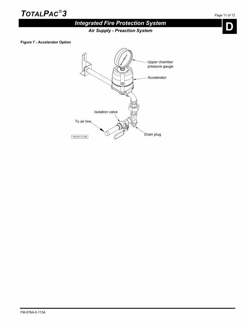
4.2 Accelerator
The Viking Model E-1 accelerator is a quick-opening device featuring automatic reset. The Viking Model E-1 accelerator is used without the anti-flood device to speed the action of a pneumatic release system on preaction system.
Operation
The Viking Model E-1 accelerator operates on the principle of unbalanced pressures. As the accelerator is pressurized, air enters the inlet chamber, goes through the screen filter into the middle chamber and through an orifice into the lower chamber. From the middle chamber, air slowly enters the upper chamber through a filtered orifice restriction in the cover diaphragm.
In the SET position, the system air pressure is the same in all chambers. When a sprinkler or release device operates, the pressure in the middle and lower chambers is reduced at the same rate as the system pressure. The orifice restriction in the cover diaphragm restricts the air flow from the upper chamber, temporarily causing higher pressure in the upper chamber.
The pressure differential forces the cover diaphragm down, pushing the actuator rod down. This action vents the pressure from the lower chamber to the outlet vent, allowing residual pressure in the inlet chamber to force the clapper diaphragm open. After the clapper diaphragm opens, any pressure remaining in the inlet chamber and associated piping is vented to atmosphere.
On a preaction system, when the accelerator operates, the outlet pressure is vented to atmosphere, speeding the release system operation.
To enable the accelerator device
1. OPEN the isolation valve of the accelerator.
CAUTION ! The system air pressure should be higher or equal to the upper chamber of the accelerator prior to opening the main water supply valve (D1).
Note : Ensure that the isolation valve of the accelerator is open in normal supervisory mode.
To isolate the accelerator device
This operation can be necessary in order to verify the pressure adjustments or to allow the pressure switches adjustments.
1. CLOSE the isolation valve of the accelerator.
Refer to instructions described on Viking datasheet #122 (form No. 071692).
To reset the accelerator device
Make sure the system is properly drained and reset. Observe the upper chamber pressure of the accelerator. The gauge must read zero before the accelerator will automatically reset. It may be necessary to loosen, remove and re-install the accelerator air gauge (using the appropriate wrench) to vent trapped air pressure from the upper chamber, even when the gauge indicates zero if the air supply is on while performing the reset.
Make sure system is pressurized according to recommended settings.
WARNING Do not exceed 60 PSI (414 kPa).
After every operation, and each time water is allowed to enter the system
1. Inspect the interior of the accelerator for the presence of water. Dampness or condensation may indicate that the air supply is not being dried adequately. If water is allowed to enter the middle or upper chamber of the accelerator, it may contaminate the accelerator orifices and prevent it from operating properly.
2. Remove the 1/2"-NPT (15 mm) plug from the base of the accelerator. If water or dampness is present, the accelerator must be disassembled, cleaned and dried. For more information about this procedure, refer to Viking datasheet #122 (form No. 071692).
3. Weekly inspection is recommended unless system is provided with low air supervisory signal, then monthly inspection may be adequate.
4. Check the upper chamber pressure of the accelerator. The air pressure should be equal to the air pressure maintained in the system on which it is installed.
A difference in pressure other then slight variation due to gauge calibration may indicate gauge malfunction, plugged accelerator orifices and/or filters, or other maintenance is required.
Note : Standard tolerance allowance in pressure gauge calibration may result in a slight variation when pressure readings of any two gauges are compared.
5. Verify that all other trim valves are in their normal operating position.
6. Check for signs of mechanical damage and/or corrosive activity. If detected, perform maintenance as required or, if necessary, replace device.
7. Verify that the main water supply valve (D1) is OPEN and secure and that the by-pass valve (1) is OPEN.
TOTALPAC ®3 Page 11 of 12
Integrated Fire Protection System D Air Supply - Preaction System
FM-076A-0-113A
Figure 7 - Accelerator Option
Upper chamberpressure gauge
Drain plug
To air line
Accelerator
Isolation valve
FM-061H-0-125B

Page 12 of 12 TOTALPAC ®3
D Integrated Fire Protection System
Air Supply - Preaction System
FM-076A-0-113A
This page is left intentionally blank.

TOTALPAC ®3 Page 1 of 8
Integrated Fire Protection System E Control Section
FM-076A-0-89C
1. Self-contained unit with integrated release control panel
1.1 Product description The release control panel of the TOTALPAC ®3 system is an add-on unit that is installed inside the cabinet at the factory. Once the left door is opened, the locked control panel door can be opened to give access to the control panel, the emergency battery compartment, and other related equipment. A releasing circuit disconnect switch is located at left of the release control panel. The control panel can be easily flipped once unlatched from the right side, giving access to electrical junction's box of the unit.
1.2 Self-contained unit with Viking VFR-400 release control panel
The Viking release control panel model VFR-400 is a listed and approved, microprocessor based fire control/releasing panel. The battery compartment can hold two 12 volt batteries which are charged by an internal battery charger. Batteries are available to provide up to 90 hours of backup power during AC power failure. The VFR-400 panel can be used with a wide range of compatible initiating devices such as pull stations, heat detectors (including linear heat detectors), photo-electric and ionization smoke detectors.
For complete compatibility list, please see the Viking VFR-400 Installation, operation and instruction manual provided with the TOTALPAC ®3 unit.
Pre-configured programs allow field programming for one of ten possible input/output combinations that are available and listed for use with the TOTALPAC ®3 system. A field wiring electrical junction boxes is integrated with the cabinet for connection of detection system, auxiliary contacts and signaling devices. All supply, inputs & outputs are factory wired from the control panel to terminal strips (TBA, TBB & TBC) for contractor's field wiring (see figure 4 and the section F ELECTRICAL). Gauges to indicate air, water supply pressure and priming water pressure are all visible through clear Lexan windows on the left door.
1.3 Technical Data
Cabinet Steel enclosure: Refer to section G CABINET SECTION for further details. Temperature: 39°F (4°C) to 120°F (48°C) Humidity: 85% relative humidity (non-condensing) at 90°F (32°C) maximum
AC Power Releasing control panel AC power shall be supplied by a dedicated circuit breaker, as per NFPA 70, Section 760 and Canadian Electrical Code, Section 32. The panel is available for use with either 120VAC, 60Hz or 220/240VAC, 50/60Hz power supply. The unit may be provided with an air compressor. Refer to section D AIR SUPPLY to determine applicable power requirements.
Note : Branch circuit for the air compressor shall not be the same as the release control panel power source.
1.4 Visual Indicators Red LED’s:
- Initiating device circuit active (4) - Notification/Release circuit active (4) - Common alarm
Green LED: - AC power
Yellow LED’s: - Initiating device circuit trouble (4) - Output circuit trouble (4) - Supervisory initiating zone (4) - Supervisory bell output active (4) - Supervisory 1 - Supervisory 2 - Power trouble - Supervisory trouble - System trouble - Ground fault - Discharging/Pre-Discharge - Alarm silenced

Page 2 of 8 TOTALPAC ®3
E Integrated Fire Protection System Control Section
FM-076A-0-89C
1.5 Control buttons SCROLL UP / BUZZER SILENCE and SCROLL DOWN / BUZZER SILENCE: When a trouble or supervisory event occurs, a press of this button will acknowledge each viewed event and the appropriate output will silence, as well as the applicable LED. The applicable TROUBLE or SUPERVISORY input LED will change from flashing to steady. The message of the first line on the display will be terminated with ACK for each acknowledged event input. Once all events in trouble or supervisory state have been viewed, the panel buzzer will silence. A subsequent trouble or supervisory event will resume the panel buzzer. Trouble events are self-restoring. Supervisory events latch and require a reset to be cleared. SIGNAL SILENCE: By pressing SIGNAL SILENCE button, all silenceable outputs will de-activate, as well as the applicable LED. A trouble condition will be created, the TROUBLE contact will be activated and the yellow ALARM SILENCE LED will light.
WARNING ! Alarms initiated from a WATERFLOW signal cannot be silenced. The panel must be reset to silence audible devices.
SYSTEM RESET: The RESET button breaks power to all initiating circuits, 4-wire smoke detectors power and will clear any activated output circuits. If any alarm, supervisory or trouble still exists after reset, they will reactivate the control panel.
1.6 Time & date settings
1. Slide the program switch down to PROGRAM position.
2. Press on FUNCTION button until the following is displayed.
SET TIME?
3. Press the SELECT button to get to the MINUTES sub-menu.
01/21/2000
MINUTES 02:58:04
Use SELECT button to increase the minutes, or use SET button to decrease minutes.
4. Press the FUNCTION button to get to the HOURS sub-menu.
01/21/2000
HOURS 02:58:04
Use SELECT button to increase the hours, or use SET button to decrease hours.
5. Press the FUNCTION button to get to the DAY sub-menu.
DAY 01/21/2000
02:58:04
Use SELECT button to increase day, or use SET button to decrease day.
6. Press the FUNCTION button to get to the MONTH sub-menu.
MONTH 01/21/2000
02:58:04
Use SELECT button to increase month, or use SET button to decrease month.
7. Press the FUNCTION button to get to the YEAR sub-menu.
YEAR 01/21/2000
02:58:04
Use SELECT button to increase year, or use SET button to decrease year.
8. Slide the program switch up to RUN position.

TOTALPAC ®3 Page 3 of 8
Integrated Fire Protection System E Control Section
FM-076A-0-89C
Figure 1 – Cabinet layout
CONTROLPANEL
SYSTEM AIRPRESSURE
FM-061H-0-126A-1
MANUALEMERGENCY
RELEASE
PRIMINGPRESSURE
WATER INLETPRESSURE

Page 4 of 8 TOTALPAC ®3
E Integrated Fire Protection System Control Section
FM-076A-0-89C
Figure 2 - Control equipment layout
RELEASING CIRCUITDISCONNECT SWITCH
VFR-400
ZONE 4
AC POWER SUP1 / ABORT
STEADY: DISCHARGED
ALARM SILENCE
COMMON ALARM
FLASHING: PRE-
SUPERVISORY 2POWER TBL
SYSTEM TBL
GROUNDFAULTPROGRAM
VIEWING ANGLE
BUZZER SILENCESCROLL-UP
BUZZER SILENCESCROLL-DOWN
SELECT
FUNCTION
MODEPROGRAM
MODE
SIGNAL SILENCE
SYSTEM RESET
RUN
DISCHARGE
RED OUTPUT LED STEADY: ABORT
SUPV TBL
TB102 TB103
TB101TB1TB201LN
AC INCONNECTOR
S24VDC
NON-RESETTABLERS485 AUX
24VDC
SUP 1 SUP 2VALVE
TAMPERSUPERVISORY
LOW AIR
ZONE 1HEAT / SMOKEDETECTORS
ZONE 2HEAT / SMOKEDETECTORS
ZONE 3WATER FLOW
SWITCH
ZONE 4MANUALSTATION
GENERALALARM
OUTPUT 1
WATER FLOWBELL
OUTPUT 2
RELEASECIRCUIT
OUTPUT 3
SUPERVISORYBELL
OUTPUT 4
BATT
NON-POWER LIMITEDSUPERVISED COM NO NC
TROUBLE
COM NO NC
ALARM
COM NO
SUPV
COM NO
WTRFLW
RUN
SET
ZONE 3
ZONE 2
ZONE 1
OUTPUT 2
OUTPUT 1
OUTPUT 3
OUTPUT 4
RESETTABLE
POWER
SW5
5
DISABLE SWITCH
SYSTEM DISABLED
SYSTEM NORMAL
RELEASING CIRCUIT
UNLATCH TO OPENTHE RIGHT DOOR(or rotate the control panel)
12VDC BATTERY SET
AIR COMPRESSORISOLATING SWITCH (E15)
CONTROL PANEL(shown with door open)
UNLATCH TO ROTATETHE CONTROL PANEL
JUNCTIONS BOX(behind control panel)
FM-061H-0-144A
Figure 3 - Detail of VFR-400 User interface
VFR-400
ZONE 4
AC POWER SUP1 / ABORT
STEADY: DISCHARGED
ALARM SILENCE
COMMON ALARM
FLASHING: PRE-
SUPERVISORY 2POWER TBL
SYSTEM TBL
GROUNDFAULTPROGRAM
VIEWING ANGLE
BUZZER SILENCESCROLL-UP
BUZZER SILENCESCROLL-DOWN
SELECT
FUNCTION
MODEPROGRAM
MODE
SIGNAL SILENCE
SYSTEM RESET
RUN
DISCHARGE
RED OUTPUT LED STEADY: ABORT
SUPV TBL
RUN
SET
ZONE 3
ZONE 2
ZONE 1
OUTPUT 2
OUTPUT 1
OUTPUT 3
OUTPUT 4
LAMP TEST
FM-061H-0-143A

TOTALPAC ®3 Page 5 of 8
Integrated Fire Protection System E Control Section
FM-076A-0-89C
Figure 4 - Junction box layout and detail of wiring routing
F
TBA & TBC Terminals
TBB Terminals
Factory Wired Air CompressorIsolating Switch (E15)
AC POWER110/120VAC, 50/60Hz or
220/240VAC, 50/60Hz
OPTIONAL ARM-44 RELAY MODULE
POWER LIMITED CIRCUITS
TBB
TBA
TBC
Refer to Electrical Sectionfor Wiring Diagrams.
DETECTION & SUPERV. RELAY CONTACTS OPT.RS485
FM-061H-0-142A
NOTE : Junction box is located behind the control panel once rotated. It is shown with cover removed.
All conduits are installedby the Contractor through1/2" and 3/4" knock-outs
Page 6 of 8 TOTALPAC ®3
E Integrated Fire Protection System Control Section
FM-076A-0-89C
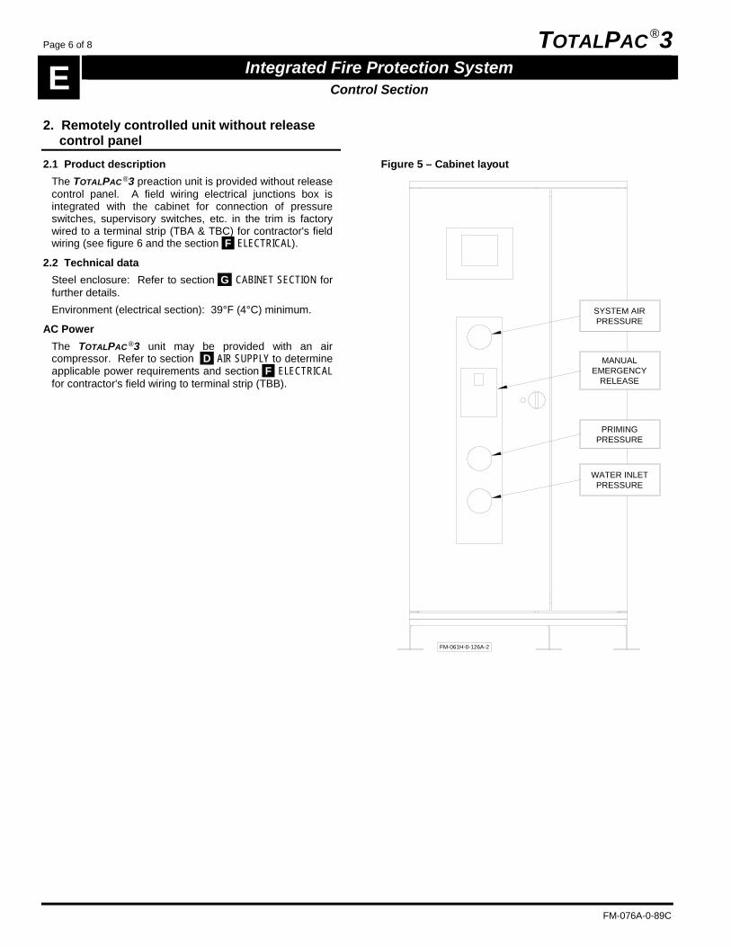
2. Remotely controlled unit without release control panel
2.1 Product description The TOTALPAC ®3 preaction unit is provided without release control panel. A field wiring electrical junctions box is integrated with the cabinet for connection of pressure switches, supervisory switches, etc. in the trim is factory wired to a terminal strip (TBA & TBC) for contractor's field wiring (see figure 6 and the section F ELECTRICAL).
2.2 Technical data Steel enclosure: Refer to section G CABINET SECTION for further details. Environment (electrical section): 39°F (4°C) minimum.
AC Power The TOTALPAC ®3 unit may be provided with an air compressor. Refer to section D AIR SUPPLY to determine applicable power requirements and section F ELECTRICAL for contractor's field wiring to terminal strip (TBB).
Figure 5 – Cabinet layout
PRIMINGPRESSURE
WATER INLETPRESSURE
MANUALEMERGENCY
RELEASE
SYSTEM AIRPRESSURE
FM-061H-0-126A-2

TOTALPAC ®3 Page 7 of 8
Integrated Fire Protection System E Control Section
FM-076A-0-89C
Figure 6 - Junctions box layout for system without release control panel
TBC
Refer to Electrical Sectionfor Wiring Diagrams.
DISABLE SWITCH
SYSTEM DISABLED
SYSTEM NORMAL
RELEASING CIRCUIT
TBB
TBA
FM-061H-0-149B
Factory Wired Air Compressoror Excess Pressure PumpIsolating Switch (E15)
AC POWER120VAC, 50/60Hz or
220/240VAC, 50/60Hz
All conduits are installedby the Contractor through1/2" and 3/4" knock-outs
SYSTEM DEVICES
OPT.
F
Releasing circuitDisconnect switchTBB Terminals
TBA & Optional TBC Terminals
POWER LIMITED CIRCUITS

Page 8 of 8 TOTALPAC ®3
E Integrated Fire Protection System Control Section
FM-076A-0-89C
This page is left intentionally blank.

TOTALPAC ®3 Page 1 of 10
Integrated Fire Protection System F Electrical Section - Double Interlock Preaction System - Electric/Pneumatic Release
FM-076A-0-66A
1. Self-contained configurations
The Viking VFR-400 releasing control panel integrated within the TOTALPAC ®3 unit is factory wired and programmed with the configuration selected at the time of purchase.
All field wiring is to be wired to the contractor wiring junction box and terminals provided (TBA, TBB & TBC).
WARNING Only the following pre-configured programs are Listed/Approved with the actual TOTALPAC ®3 Unit. Changing for another pre-configured program may alter the fire protection capabilities of the system and/or void Listing/Approval and warranty. Consult FireFlex Systems before making any change.
1.1 Releasing circuit disconnect switch
A key switch located at left of the release control panel, allows the user to electrically disconnect the N.C. solenoid valve for maintenance purpose. A supervisory signal and a trouble signal are present at the release control panel.
When disabled, the TOTALPAC ®3 unit remains operational with the opening of the manual emergency release valve, unless the main water supply valve is closed.
1.2 Electric/pneumatic release (single zones)
Program #1: Single hazard, two alarm zones, one manual release zone, one water flow zone and two supervisory zones.
On activation of either DETECTION ZONE 1 (detection) or DETECTION ZONE 2 (detection), or the activation of DETECTION ZONE 4 (manual release), the system alarm audible devices sound and if required, can be silenced manually. The N.C. (normally closed) solenoid valve of the system is energized. When air pressure is released from the piping network, it allows the water to escape from the priming chamber of the deluge valve. The clapper of the deluge valve opens, filling the outlet chamber and sprinklers piping network with water. The DETECTION ZONE 3 (water flow) is activated. System water flow audible devices and the water motor gong (if installed) will sound. Water is discharged through opened automatic sprinklers.
Note: When DETECTION ZONE 3 (water flow) is activated, the alarm audible devices sound and cannot be silenced.
On activation of SUPERVISORY ZONE 1 (low air pressure) or SUPERVISORY ZONE 2 (valve tamper), supervisory audible devices will sound.
Table 1 - Program #1: Output and relay circuits activated by input circuits
PROGRAM #1 DOUBLE INTERLOCK PREACTION ELECTRIC/PNEUMATIC RELEASE
(SINGLE ZONES)
OUTPUT CIRCUITS (NAC)
RELAY CIRCUITS EVENTS
1 2 3 4
TR
OU
BLE
RE
LAY
AL
AR
M R
ELA
Y
SU
PE
RV
ISO
RY
RE
LAY
WA
TE
RF
LOW
RE
LAY
PR
EA
CT
ION
FIL
LIN
G
WIT
H W
AT
ER
PR
EA
CT
ION
RE
LEA
SIN
G
IN H
AZ
AR
D
AL
AR
M B
EL
L
WA
TE
RF
LOW
BE
LL
RE
LEA
SE
SO
LEN
OID
SU
PE
RV
ISO
RY
BE
LL
INPUT CIRCUITS
SUPERVISORY ZONE
1 Low air pressure A T A
2 Valve tamper A T A
DETECTION ZONE
1 Heat/smoke detectors A A T A
2 Heat/smoke detectors A A T A
3 Water flow A A T A A
4 Manual release A A T A
EVENTS
Opening of a sprinkler without DETECTION ZONE
E E
Opening of a sprinkler after DETECTION ZONE
E E
AC power failure 1 E
Battery failure E
NAC open/short circuit E
Ground fault E
A = Alarm activated (on short circuit) T = Trouble activated (on open circuit) E = Event actuated
(1) Trouble relay will activate 90 minutes after trouble LED and local buzzer.

Page 2 of 10 TOTALPAC ®3
F Integrated Fire Protection System
Electrical Section - Double Interlock Preaction System - Electric/Pneumatic Release
FM-076A-0-66A
1.3 Electric/pneumatic release (crossed zones)
Program #12: Single hazard, two alarm zones, one manual release zone, one water flow zone and two supervisory zones.
On activation of both DETECTION ZONE 1 (detection) and DETECTION ZONE 2 (detection), or the activation of DETECTION ZONE 4 (manual release), the system alarm audible devices sound and if required, can be silenced manually. The normally closed (N.C.) solenoid valve of the system is energized. When air pressure is released from the piping network, it allows the water to escape from the priming chamber of the deluge valve. The clapper of the deluge valve opens, filling the outlet chamber and sprinklers piping network with water. The DETECTION ZONE 3 (water flow) is activated. System water flow audible devices and the water motor gong (if installed) will sound. Water is discharged through opened automatic sprinklers.
Note: When DETECTION ZONE 3 (water flow) is activated, the alarm audible devices sound and cannot be silenced.
On activation of SUPERVISORY ZONE 1 (valve tamper) or SUPERVISORY ZONE 2 (low air pressure), supervisory audible devices will sound.
Table 2 - Program #12: Output and relay circuits activated by input circuits
PROGRAM #12 DOUBLE INTERLOCK PREACTION ELECTRIC/PNEUMATIC RELEASE
(CROSSED ZONES)
OUTPUT CIRCUITS (NAC)
RELAY CIRCUITS EVENTS
1 2 3 4
TR
OU
BLE
RE
LAY
AL
AR
M R
ELA
Y
SU
PE
RV
ISO
RY
RE
LAY
WA
TE
RF
LOW
RE
LAY
PR
EA
CT
ION
FIL
LIN
G
WIT
H W
AT
ER
PR
EA
CT
ION
RE
LEA
SIN
G
IN H
AZ
AR
D
AL
AR
M B
EL
L
WA
TE
RF
LOW
BE
LL
RE
LEA
SE
SO
LEN
OID
SU
PE
RV
ISO
RY
BE
LL
INPUT CIRCUITS
SUPERVISORY ZONE
1 Valve tamper A T A
2 Low air pressure A T A
DETECTION ZONE
1 Heat/smoke detectors A X
T A
2 Heat/smoke detectors A T A
3 Water flow A A T A A
4 Manual release A A T A
EVENTS
Opening of a sprinkler without DETECTION ZONE
E E
Opening of a sprinkler after DETECTION ZONE
E E
AC power failure 1 E
Battery failure E
NAC open/short circuit E
Ground fault E
A = Alarm activated (on short circuit) T = Trouble activated (on open circuit) E = Event actuated X = Crossed zones
(1) Trouble relay will activate 90 minutes after trouble LED and local buzzer.

TOTALPAC ®3 Page 3 of 10
Integrated Fire Protection System F Electrical Section - Double Interlock Preaction System - Electric/Pneumatic Release
FM-076A-0-66A
Figure 1 - Field wiring diagrams
WIRING INCLASS B / STYLE B
RS485
UL-Listed24VDC, 4-Wire Smoke Detectors
24VDC
COM
220/240VAC, 50Hz, 1.5KW MAX
115VAC, 60Hz, 1.5HP MAX
208/230VAC, 60Hz, 2HP MAX
WIRING INCLASS B / STYLE Y
OPTIONAL WIRING INCLASS A / STYLE D
24VDC
COM
2/6 29
30
PAM-4Power SupervisoryRelay (EOL Relay)
POWER LIMITED 4-WIRE DETECTION CIRCUIT
5.1KEOLR
5.1KEOLR
5.1KEOLR
5.1KEOLR
5.1KEOLR
5.1KEOLR
5.1KEOLR
120
25
26
27
28
29
30
LEGEND
BELL OR HORN
End-of-line devices are not required forClass A / Style D wiring.
Control panel AC power source is supervised and non-power limited.
Refer to Local Electrical Codes for wiring size.
1/5
TB
A
6 7 8 9 10
11
C NO
NC
MA
IN V
AL
VE
SU
PE
RV
ISO
RY
C NO
NC
SH
UT
-OF
FV
AL
VE
SU
PE
RV
ISO
RY
Contact provided for connection tothe building's central Fire Alarm Panel.
OPTIONAL
LOS ANGELES OPTION
CHICAGO OPTION
NOTE:
Class A / Style D requires CA2Z modules.NOTES:
All devices are shown in their normal supervisory state.
NOTES:
Use dry contacts with power limited circuits only.
CONTACTS RATED:5A, 1/6HP, 125/250VAC0.5A, 250VDC 0.25A, 250VDC
HEAT DETECTOR
SMOKE DETECTOR
MANUAL RELEASE
DRY CONTACT
END OF LINE RESISTOR
1
TB
C
2 3 4 5
24V
DC
NO
N-
RE
SE
TT
AB
LE
SH
IELD
LINE
NEUTRAL
GROUND
GROUND
NEUTRAL
LINE
120VAC, 60Hz, 165VA MAX
220VAC, 50Hz, 185VA MAXCONTROLPANEL
AIRCOMPRESSOR
CONTACTS RATED 3A, 30VDC RESISTIVE
WIRING OF INPUT POWER SOURCES
WITH AIR OPTION "A" ONLY
Branch circuit for air compressor shall not be the sameas the control panel power source.
24V
DC
RE
SE
TT
AB
LE
C NO
NC
C NO
NC
C NO
C NO
ALA
RM
TR
OU
BLE
SU
PE
RV
ISO
RY
WA
TE
R F
LO
W
DE
TE
CT
ION
ZO
NE
2
MA
NU
AL
PU
LL
ST
AT
ION
SZ
ON
E 4
NA
C1
SIL
EN
CE
AB
LE
ALA
RM
NA
C2
NO
N-S
ILE
NC
EA
BLE
WA
TE
RF
LOW
NA
C4
SIL
EN
CE
AB
LE
SU
PE
RV
ISO
RY
DE
TE
CT
ION
ZO
NE
1
DE
TE
CT
ION
ZO
NE
2
MA
NU
AL
PU
LL
ST
AT
ION
SZ
ON
E 4
DE
TE
CT
ION
ZO
NE
12 3 4 5 6 7 8 9 10
11
12
1
2
3
4
TBB
5
6
1
TB
A
2 3 4 5 6 7 8 9 10
11
12
13
14
15
16
17
18
19
20
21
22
23
24
FM-061H-0-83A
1
TB
A
Power limited (supervised) initiating device circuits
Zones 1 (detection), 2 (detection) and 4 (manual release): Max. loop resistance: 100Ω End of line: 5.1K ohms, 1/4W Leave ELR (provided) on all unused circuits.
Refer to the VFR-400 release control panel manual for device compatibility.
Auxiliary power 24Vdc regulated source Total current available: 0.2A Resettable for 4 wires smoke detectors
Power limited (supervised) notification appliance circuits
Output circuits 1, 2 and 4: Maximum operating voltage: 27Vdc (ripple: 0.3Vdc) Maximum usable current per circuit: 1.0A Total current available (all circuits): 2.5A Polarity is reversed in supervisory condition. Leave ELR (provided) on all unused circuits.
Refer to the VFR-400 release control panel manual for device compatibility

Page 4 of 10 TOTALPAC ®3
F Integrated Fire Protection System
Electrical Section - Double Interlock Preaction System - Electric/Pneumatic Release
FM-076A-0-66A
1.4 Electric/pneumatic release, NYC (single zone)
Program #5: Single hazard, one alarm zone, one manual release zone, one water flow zone and three supervisory zones.
On activation of DETECTION ZONE 1 (detection) or DETECTION ZONE 4 (manual release), the system alarm audible devices sound and if required, can be silenced manually. The normally closed (N.C.) solenoid valve of the system is energized. When air pressure is released from the piping network, it allows the water to escape from the priming chamber of the deluge valve. The clapper of the deluge valve opens, filling the outlet chamber and sprinklers piping network with water. The DETECTION ZONE 3 (water flow) is activated. System water flow audible devices and the water motor gong (if installed) will sound. Water is discharged through opened automatic sprinklers.
Note: When DETECTION ZONE 3 (water flow) is activated, the alarm audible devices sound and cannot be silenced.
On activation of SUPERVISORY ZONE 1 (valve tamper), SUPERVISORY ZONE 2 (low air pressure) or DETECTION ZONE 2 (very low air pressure), supervisory audible devices will sound.
Table 3 - Program #5: Output and relay circuits activated by input circuits
PROGRAM #5 DOUBLE INTELOCK PREACTION ELECTRIC/PNEUMATIC RELEASE
(NYC - SINGLE ZONE)
OUTPUT CIRCUITS (NAC) RELAY CIRCUITS EVENTS
1 2 3 4
TR
OU
BLE
RE
LAY
AL
AR
M R
ELA
Y
SU
PE
RV
ISO
RY
RE
LAY
WA
TE
RF
LOW
RE
LAY
PR
EA
CT
ION
FIL
LIN
G
WIT
H W
AT
ER
PR
EA
CT
ION
RE
LEA
SIN
G
IN H
AZ
AR
D
AL
AR
M B
EL
L
SU
PE
RV
ISO
RY
BE
LL
RE
LEA
SE
SO
LEN
OID
TR
OU
BLE
BE
LL
INPUT CIRCUITS
SUPERVISORY ZONE
1 Valve tamper A T T A
2 Low air pressure A T T A
DETECTION ZONE
1 Heat/smoke detectors A A T T A
2 Very low air pressure A T T A
3 Water flow A T T A A
4 Manual release A A T T A
EVENTS
Opening of a sprinkler without DETECTION ZONE
E E
Opening of a sprinkler after DETECTION ZONE
E E
AC power failure 1 E E
Battery failure E E
NAC open/short circuit E E
Ground fault E E
A = Alarm activated (on short circuit) T = Trouble activated (on open circuit) E = Event actuated
(1) Trouble relay will activate 90 minutes after trouble LED and local buzzer.

TOTALPAC ®3 Page 5 of 10
Integrated Fire Protection System F Electrical Section - Double Interlock Preaction System - Electric/Pneumatic Release
FM-076A-0-66A
Figure 2 - Field wiring diagrams
FM-061H-0-84A
1
TB
A
24V
DC
NO
N-
RE
SE
TT
AB
LE
SH
IELD
RS4852
5
262 3 4 5 6 7 8 9 10
11
12
13
14
15
16
17
18
19
20
21
22
23
24
24V
DC
RE
SE
TT
AB
LE
C NO
NC
C NO
NC
C NO
C NO
ALA
RM
TR
OU
BLE
SU
PE
RV
ISO
RY
WA
TE
R F
LO
W
MA
NU
AL
PU
LL
ST
AT
ION
SZ
ON
E 4
NA
C1
SIL
EN
CE
AB
LE
ALA
RM
NA
C2
SIL
EN
CE
AB
LE
SU
PE
RV
ISO
RY
NA
C4
SIL
EN
CE
AB
LE
TR
OU
BL
E
DE
TE
CT
ION
ZO
NE
1
1
TB
C
2 3 4 5
5.1KEOLR
5.1KEOLR
5.1KEOLR
5.1KEOLR
5.1KEOLR
5.1KEOLR
120
WIRING INCLASS B / STYLE Y
WIRING INCLASS B / STYLE B
OPTIONAL WIRING INCLASS A / STYLE D
UL-Listed24VDC, 4-Wire Smoke Detectors
Class A / Style D requires CA2Z modules.NOTES:
End-of-line devices are not required forClass A / Style D wiring.
TB
A
All devices are shown in their normal supervisory state.
NOTES:
Use dry contacts with power limited circuits only.
Control panel AC power source is supervised and non-power limited.
1
TB
A
2 25
26
24VDC
COMPAM-4Power SupervisoryRelay (EOL Relay)
CONTACTS RATED 3A, 30VDC RESISTIVE
1 2 3 4 5 6 7 8
MA
NU
AL
PU
LL
ST
AT
ION
SZ
ON
E 4
DE
TE
CT
ION
ZO
NE
1
24VDC
COM
POWER LIMITED 4-WIRE DETECTION CIRCUIT
HEAT DETECTOR
SMOKE DETECTOR
MANUAL RELEASE
DRY CONTACT
END OF LINE RESISTOR
LEGEND
BELL OR HORN
1
2
3
4
TBB
5
6
LINE
NEUTRAL
GROUND
GROUND
NEUTRAL
LINE
120VAC, 60Hz, 165VA MAX
220VAC, 50Hz, 185VA MAXCONTROLPANEL
AIRCOMPRESSOR
WIRING OF INPUT POWER SOURCES
WITH AIR OPTION "A" ONLY
Branch circuit for air compressor shall not be the sameas the control panel power source.
Refer to Local Electrical Codes for wiring size.
220/240VAC, 50Hz, 1.5KW MAX
115VAC, 60Hz, 1.5HP MAX
208/230VAC, 60Hz, 2HP MAX
Power limited (supervised) initiating device circuits
Zones 1 (detection) and 4 (manual release): Max. loop resistance: 100Ω End of line: 5.1K ohms, 1/4W Leave ELR (provided) on all unused circuits.
Refer to the VFR-400 release control panel manual for device compatibility.
Auxiliary power 24Vdc regulated source Total current available: 0.2A Resettable for 4 wires smoke detectors
Power limited (supervised) notification appliance circuits
Output circuits 1, 2 and 4: Maximum operating voltage: 27Vdc (ripple: 0.3Vdc) Maximum usable current per circuit: 1.0A Total current available (all circuits): 2.5A Polarity is reversed in supervisory condition. Leave ELR (provided) on all unused circuits.
Refer to the VFR-400 release control panel manual for device compatibility

Page 6 of 10 TOTALPAC ®3
F Integrated Fire Protection System
Electrical Section - Double Interlock Preaction System - Electric/Pneumatic Release
FM-076A-0-66A
2- Optional Modules
2.1 Relay module ARM-44
The ARM-44 is an auxiliary relay module designed to operate with the VFR-400 release control panels to provide an additional 8 independent form C relay outputs in 3 different operating modes (via switch S1).
The release control panel communicates with the ARM-44 via the RS-485 and 24 VDC auxiliary power connections from the VFR-400. Be sure to set switch SW5 of the VFR-400 and switch S2 of the ARM-44 correctly.
The ARM-44 can be factory installed but could also be added inside the junction box by a qualified personal.
Figure 3 - ARM-44 wiring to VFR-400
Card address switch must be set onevalue higher than the previous one.Set the selector switch at the VFR-400accordingly.
VFR-400
Selector switch must be set according tothe total number of devices installed on theRS-485 terminals. Increment for eachdevice being added.
Relocate existing wires from TBC-1 to 4 to TB1-1 to 4of ARM-44 then rewire 4 new cables from TB1-1 to 4of ARM-44 to TBC-1 to 4.
NOTE:
Refer to the ARM-44 datasheet for operatingmodes of the ARM-44.
120
RELAY 8RELAY 5
TB
C1 2 3 4 5
S2
0987
65
4 3 2
1
1 2 3 4 5 TB1
S24VDC
NON-RESETTABLERS485SW5
0 9
87
654
32
1
WARNING
Leave the drain wire of the shielded cableconnected to terminal 5 of TBC.
2 3 4 5 6
COM NO NC
RELAY 1
COM NO NC
RELAY 2
7 8 9 10 11 12
COM NO NC
RELAY 3
COM NO NC
RELAY 4
13 14 15 16 17 18
COM NO NC COM NO NC
RELAY 6
19 20 21 22 23 24
COM NO NC
RELAY 7
COM NO NC
DIS
AB
LE
LA
TC
HM
OD
E 2
MO
DE
3M
OD
E 1
EN
AB
LE
UN
LA
TC
HE
D
S1ARM-44
TB101
FM-061H-0-82A
1 2 3 4 5 TB1
S24VDC RS485
1
Table 4 - ARM-44 S1 configuration
S1 configuration
Mode 1 Relays 1 to 4 follow the activation of zones 1 to 4, respectively.
Relays 5 to 8 follow the activation of outputs 1 to 4, respectively.
Mode 2
Relays 1 to 4 follow the activation of zones 1 to 4, respectively.
Relay 5 operates on any supervisory condition
Relay 6 operates on any trouble condition
Relays 7 and 8 operate on any alarm condition
Mode 3
Relay 1 operates on any supervisory condition
Relay 2 operates on any trouble condition
Relays 3 and 4 operate on any alarm condition
Relays 5 to 8 follow the activation of outputs 1 to 4, respectively

TOTALPAC ®3 Page 7 of 10
Integrated Fire Protection System F Electrical Section - Double Interlock Preaction System - Electric/Pneumatic Release
FM-076A-0-66A
2.2 Remote Annunciator RA-4410-RC
The RA-44410-RC remote annunciator is designed to operate with the VFR-400 release control panel. It contains 34 LED's to indicate a change in release control panel status. A local buzzer on the annunciator sounds for any trouble or supervisory condition.
The release control panel communicates with the RA-4410-RC annunciator via supervised separate connections for the RS-485 communication and the 24VDC power requirement. Separate cables should be used for communication and power. Shielded cable MUST be used for the RS-485 communication line.
Up to four remote annunciators can be connected to one control panel. Be sure to set switch SW5 of the VFR-400 and switch S2 of the RA-4410-RC correctly.
Figure 4 - RA-4410-RC wiring to TBC
120
8
4
Annunciator Side
2
RED OUTPUT LED STEADY: ABORT
S
4
TB
C Connections Side
FM-061H-0-81A
24
1
7
OUTPUT 4
3
Selector switch must be set according tothe total number of devices installed on theRS-485 terminals. Increment for eachdevice being added.
Annunciator address switch must be setone value higher than the previous one.Set the selector switch at the VFR-400accordingly.
OUTPUT 2
Connect the drain wire of the shielded cable to terminal 5 of TBC only.DO NOT connnect the drain wire to any device. The drain wire must makea connections path to the last device where it is cut off and insulated.
24VDC
0
6
2
Remove the resistor from TBC or the currentdevice and install it on the last device only.
1
SUP1 / ABORT
3
NON-RESETTABLE
5
VFR-400
WARNING
13
SW5
OUTPUT 1
9
OUTPUT 3
5
1
SUPERVISORY 2
RS485
2
S
GROUND
ZONE 1
4
S2
ZONE 2
06
ZONE 2
2
ZONE 4
TB1
AC POWER
TB
1
COMMON ALARM
7
SUPV TBL
3
1
POWER TBL
3
RS
485
5
5
8
4
OUTPUT 2
ZONE 3
24V
DC
FAULT
RA-4410-RC
9
ZONE 1
5
OUTPUT 1
SILENCE
LAMP TEST
STEADY: DISCHARGEDFLASHING: PRE-DISCHARGE
ZONE 4 OUTPUT 4
OUTPUT 3
SYSTEM TBL
ZONE 3
ALARM SILENCE

Page 8 of 10 TOTALPAC ®3
F Integrated Fire Protection System
Electrical Section - Double Interlock Preaction System - Electric/Pneumatic Release
FM-076A-0-66A
3. Remotely controlled configuration
The TOTALPAC ®3 remote controlled unit is provided without an integrated control panel since all internal supervisory and releasing devices are to be connected and supervised from a remote releasing control panel.
The remote releasing control panel shall be Listed and be compatible for sprinklers supervisory and alarm contact devices and be compatible for supervising and releasing 24VDC solenoid valve.
The remote releasing control panel is to be wired to the contractor wiring junction box and terminals provided (TBA, TBB & optional TBC) as shown in figure 5.
Notes : No connection should be made directly in the trim components as this would void warranty and might prevent the normal operation of the unit.
On skid unit, all field wiring should be made directly on the trim components.
Make sure the system will perform as required and is tested to confirm it meets all requirements, as described in section B MECHANICAL SECTION).
Figure 5 –Field wiring diagrams
2 3 4 5 6 7 8 9 10
11
12
13
14
15
16
21
22
23
24
WA
TE
R F
LO
WA
LA
RM
All devices are shown in their normal supervisory state.
NOTES:
Use dry contacts with power limited circuits only.
Contacts are rated:Pressure switches: 2A, 30VDC 10A, 125/250VACSupervisory switches: 0.5A, 125VDC 0.25A, 250VDC 5A, 1/6HP, 125/250VAC
WA
TE
R F
LOW
PR
ES
UR
E S
WIT
CH
17
18
19
20
S
N.C
. S
OL
EN
OID
VA
LV
E(s
ee ta
ble
be
low
for
ratin
gs)
SO
LE
NO
ID V
AL
VE
1
TB
C
2 3 4 5 6
C NO
NC
MA
IN V
AL
VE
SU
PE
RV
ISO
RY
C NO
NC
SH
UT
-OF
FV
AL
VE
SU
PE
RV
ISO
RY
Contacts provided for connection tothe building's central Fire Alarm Panel.
OPTIONAL
LOS ANGELES OPTION
CHICAGO OPTION
NOTE:
MA
IN V
ALV
E S
UP
ER
VIS
OR
Y S
WIT
CH
SH
UT
-OF
F V
AL
VE
SU
PE
RV
ISO
RY
SW
ITC
H
VE
RY
LO
W A
IRP
RE
SS
UR
E
SW
ITC
H
LO
W A
IRP
RE
SS
UR
E S
WIT
CH
VE
RY
LO
W A
IR P
RE
SS
UR
ES
UP
ER
VIS
OR
Y
LO
W A
IR P
RE
SS
UR
ES
UP
ER
VIS
OR
Y
EO
L
MA
IN V
AL
VE
SU
PE
RV
ISO
RY
SW
ITC
H
MA
IN V
AL
VE
SU
PE
RV
ISO
RY
SH
UT
-OF
F V
AL
VE
SU
PE
RV
ISO
RY
SW
ITC
H
SH
UT
-OF
F
VA
LV
ES
UP
ER
VIS
OR
YEOL devices (not included) must be compatible with the Release Control Panel used.
OPTIONAL
All devices are factory wired.
USED ONLYWITH NYC
OPTION
1
2
3
4
TBB
LINE
NEUTRAL
GROUND
WIRING OF AIR COMPRESSOR POWER SOURCE(WITH AIR OPTION "A" ONLY)
Refer to Local Electrical Codes for wiring size.
AIRCOMPRESSOR
220/240VAC, 50Hz, 1.5KW MAX
115VAC, 60Hz, 1.5HP MAX
208/230VAC, 60Hz, 2HP MAX
DIS
CO
NN
EC
T S
WIT
CH
SU
PE
RV
ISO
RY
24
VD
C(n
ee
de
d f
or
keys
witc
hL
ED
op
era
tion
)
LE
D P
OW
ER
RELEASING CIRCUITDISCONNECT SWITCH
25
26
27
28
29
30
EO
L
EO
L
EO
L
EO
L
EO
L
FM-061H-0-91B
1
TB
A
Table 5 - Solenoid valve electrical ratings
SOLENOID VALVE ELECTRICAL RATINGS
Viking P/N Operation
(de-energized) Voltage Watts DC amps
11591 N.C. 24VDC 10W 416mA
Notes:
1. Solenoid valve is UL Listed as Fire Protection Special System Water Control Release Service (UL 429A Product category VLTR).
2. Voltage drop: For proper operation, make sure that voltage at the solenoid valve is at least 85% of nameplate rating.

TOTALPAC ®3 Page 9 of 10
Integrated Fire Protection System F Electrical Section - Double Interlock Preaction System - Electric/Pneumatic Release
FM-076A-0-66A
3.1 Releasing circuit disconnect switch
A key switch located at the front of the junctions box, allows the user to electrically disconnect the N.C. solenoid valve for maintenance purpose. A supervisory contact is to be wired to the release control panel.
When disabled, the TOTALPAC ®3 unit remains operational with the opening of the manual emergency release valve, unless the main water supply valve is closed.

Page 10 of 10 TOTALPAC ®3
F Integrated Fire Protection System
Electrical Section - Double Interlock Preaction System - Electric/Pneumatic Release
FM-076A-0-66A
This page is left intentionally blank.

TOTALPAC ®3 Page 1 of 8
Integrated Fire Protection System G Dimensional Data & Cabinet
FM-076A-0-91D
1- Cabinet for TotalPac ®3 unit
The TotalPac ®3 unit cabinet is made of sturdy 14 gauge steel. Bottom base is made of 11 gauge and 7 gauge steel. Cabinet is available in four (4) sizes:
23" x 25" x 77" (584mm x 640mm x 1960mm) for 1½" (40mm) or 2" (50mm) system
35¾" x 25" x 77" (908mm x 640mm x 1960mm) for 3" (80mm) or 4" (100mm) system
46" x 25" x 77" (1170mm x 640mm x 1960mm) for 6" (150mm) system
54" x 31" x 81" (1370mm x 790mm x 2060mm) for 8" (200mm) system
All external and internal surfaces are rust proof coated, inside and outside, with fire red, oven baked polyester powder on phosphate base. Cabinet is provided with two doors, both provided with a neoprene gasket to absorb vibrations.
The cabinet unit is pre-assembled, pre-wired and factory tested under ISO-9001 specifications. Each cabinet door is provided with hinges that can be disassembled on site to remove the door assemblies for servicing.
Note Ground wire has to be disconnected prior to remove a door. It must be reconnected once the door is reinstalled.
Gauges to indicate water supply pressure, system air pressure and priming water pressure are all visible through clear Lexan windows.
Multiple units installation is easily achieved by jointing manifold sections together at their water inlets. Drains outlet shall remain separate and open for each unit. Refer to figure 6 OPEN DRAIN DETAILS FOR MULTIPLE UNITS.
IMPORTANT ! TotalPac ®3 unit is NOT designed to be installed where it will be subjected to outdoors and/or freezing conditions. Refer to paragraph 3 ENVIRONMENT in section A GENERAL DESCRIPTION for additional details. Subjecting the unit to conditions outside these limitations might hamper the normal operation of the system.
The release control panel of the TotalPac ®3 system is installed inside the cabinet at the factory. Refer to section E CONTROLS for additional information.
Self-contained
A field wiring electrical junctions box is integrated within the cabinet for connection to detection system, auxiliary contacts and signaling devices. All inputs & outputs are factory wired to a terminal strip (TBA, TBB and optional TBC) for contractor's field wiring. Refer to section F ELECTRICAL for additional information.
Remote controlled
A field wiring electrical junctions box is integrated within the cabinet for connection of all electrical components in the trim to remotely controlled release control panel. Pressure switches, supervisory switches, etc. are all factory wired to a terminal strip (TBA and optional TBC) for contractor's field wiring. Terminal strip TBB is required for AC power connection to air compressor. Refer to section F ELECTRICAL for additional information.
Table 1 - System weight in cabinet
System size Weight 1, 2
1½" (40mm) 450 lb (204 kg)
2" (50mm) 455 lb (206 kg)
3" (80mm) 655 lb (297 kg)
4" (100mm) 730 lb (331 kg)
6" (150mm) 1080 lb (490 kg)
8" (200mm) 1445 lb (655 kg)
(1) Without release control panel. Add 34 lb (15 kg) for TotalPac ®3 unit with release control panel & batteries.
(2) Without air compressor.

Page 2 of 8 TOTALPAC ®3
G Integrated Fire Protection System Dimensional Data & Cabinet
FM-076A-0-91D
Figure 1 - Cabinet and inlets/outlets dimensions
R
CO
NTR
OL
PAN
EL
FM-061H-0-129B
CONTROLPANEL
(except for RemoteControlled Unit)
TBA, TBB & TBC
ØC
ØB
L
K
ØA
OPTIONAL FIRE DEP'TCONNECTION OUTLET(DRILLED ONLY WHENORDERED)
TBB
D
F
N
TBA & TBC
E
N
P
G
H
T(W)
J
M
Q
WATER INLETSCH.40 GROOVED OUTLET
DRAIN - SCH.40 GROOVED OUTLET
OPTIONALSHUT-OFF VALVE
U
SPR
INKL
ER R
ISER
SCH
.40
GR
OO
VED
OU
TLET
SPR
INKL
ER R
ISER
SCH
.40
GR
OO
VED
OU
TLET
M
S(V)
Table 2 - Cabinet dimensions - dimensions are in inches (mm)
Unit size A B C D E F G H J K L M N P Q R S T U V W
1½" (40)
2" (51)
1½" (38)
2" (51)
23" (584)
25" (635)
77" (1956)
4" (102)
8¾" (222)
11½" (292)
13¾" (349)
3¾" (95)
2¾" (70)
2¾" (70)
8" (203)
11½" (292)
27" (686)
37½" (953)
41½" (1054)
34¼" (870)
43½" (1105)
47" (1194)
2" (50)
2" (51)
2" (51)
2" (51)
23" (584)
25" (635)
77" (1956)
4" (102)
8¾" (222)
11½" (292)
13¾" (349)
3¾" (95)
2¾" (70)
2¾" (70)
8" (203)
11½" (292)
27" (686)
38" (965)
42" (1067)
34¾" (883)
44½" (1130)
48½" (1232)
3" (80)
4" (102)
3" (76)
2" (51)
35¾" (908)
25" (635)
77" (1956)
4" (102)
10" (254)
11½" (292)
13¾" (349)
3¾" (95)
2¾" (70)
2¾" (70)
11¾" (298)
11½" (292)
39¾" (1010)
44" (1118)
47¾" (1213)
37" (940)
51" (1295)
54¾" (1391)
4" (100)
4" (102)
4" (102)
2" (51)
35¾" (908)
25" (635)
77" (1956)
4" (102)
10" (254)
11½" (292)
13¾" (349)
3¾" (95)
2½" (64)
2½" (64)
12" (305)
11½" (292)
39¾" (1010)
48½" (1232)
53" (1346)
42" (1499)
56½" (1435)
61" (1549)
6" (150)
6" (152)
6" (152)
2" (51)
46" (1168)
25" (635)
77" (1956)
4" (102)
11" (279)
11½" (292)
13¾" (349)
3¾" (95)
5¼" (133)
5¼" (133)
17¾" (451)
11½" (292)
50" (1270)
59¼" (1505)
65¼" (1657)
51½" (1308)
70¼" (1784)
76¼" (1937)
8" (200)
8" (203)
8" (203)
2" (51)
54" (1372)
31" (787)
81" (2057)
4" (102)
12" (305)
13¼" (337)
17" (432)
3¾" (95)
9" (229)
6¾" (171)
27" (686)
13¼" (337)
58" (1473)
70" (1778)
75¼" (1911) N/A N/A N/A
Notes: 1. Dimensions are nominal and may vary ±¼" (±5mm). 2. Dimensions U, V & W are for optional fire department connection.

TOTALPAC ®3 Page 3 of 8
Integrated Fire Protection System G Dimensional Data & Cabinet
FM-076A-0-91D
Figure 2 - Floor anchoring dimensions
1" (25mm)
A
FRONT
5" (127mm)
BTOP VIEW
Ø ¾" (19mm) TYP. Ø ¾" (19mm) TYP.
FM-061H-0-128A-2
A
FRONT
TOP VIEW
1" (25mm)
B
5" (127mm)
Table 3 - Floor anchoring dimensions
Unit size A B 1½
(40mm) 25"
(635mm) 15"
(380mm) 2"
(50mm) 25"
(635mm) 15"
(380mm) 3"
(80mm) 37¾"
(959mm) 15"
(380mm) 4"
(100mm) 37¾"
(959mm) 15"
(380mm) 6"
(150mm) 48"
(1220mm) 15"
(380mm) 8"
(200mm) 56"
(1422mm) 21"
(530mm)
Figure 3 - Cabinet & doors clearance detail
TOTALPAC 3UNIT
FM-061H-0-275A-1
B min.
C min.
A min.
B min.
TYPICALMECHANICAL
ROOM
Figure 4 - Knockouts details
2½" Typ.(65mm)
9"(230mm)
High voltage
Low voltage
Combined ½ & ¾ knockouts
2½"(65mm)
FM-061H-0-68B-12
Top of Cabinet
8½"(215mm)
3"(75mm)
Table 4 - Cabinet clearance dimensions
Unit size A B C 1½
(40mm) 24"
(610mm) 12"
(305mm) 48"
(1219mm) 2"
(50mm) 24"
(610mm) 12"
(305mm) 48"
(1219mm) 3"
(80mm) 24"
(610mm) 12"
(305mm) 60"
(1524mm) 4"
(100mm) 24"
(610mm) 12"
(305mm) 60"
(1524mm) 6"
(150mm) 24"
(610mm) 12"
(305mm) 70"
(1778mm) 8"
(200mm) 32"
(813mm) 12"
(305mm) 78"
(1981mm)
Note : Minimum dimensions are according to door clearance and external piping requirements.
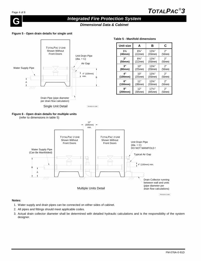
Page 4 of 8 TOTALPAC ®3
G Integrated Fire Protection System Dimensional Data & Cabinet
FM-076A-0-91D
Figure 5 - Open drain details for single unit
B
4'' (100mm)min.
TOTALPAC 3 UnitShown Without
Front Doors
FM-061H-0-139A
Drain Pipe (pipe diameterper drain flow calculation)
Water Supply Pipe
A
Single Unit Detail
Unit Drain Pipe(dia. = C)
Air Gap
Table 5 - Manifold dimensions
Unit size A B C 1½
(40mm) 8¾"
(222mm) 13¾"
(350mm) 2"
(50mm) 2"
(50mm) 8¾"
(222mm) 13¾"
(350mm) 2"
(50mm) 3"
(80mm) 10"
(255mm) 13¾"
(350mm) 2"
(50mm) 4"
(100mm) 10"
(255mm) 13¾"
(350mm) 2"
(50mm) 6"
(150mm) 11"
(280mm) 13¾"
(350mm) 2"
(50mm) 8"
(200mm) 12"
(305mm) 17½"
(445mm) 2"
(50mm)
Figure 6 - Open drain details for multiple units (refer to dimensions in table 5)
TOTALPAC 3 UnitShown Without
Front Doors
Drain Collector runningbetween wall and units(pipe diameter perdrain flow calculations)
Typical Air Gap
TOTALPAC 3 UnitShown Without
Front Doors
4'' (100mm) min.B
FM-061H-0-140A
A
12''(305mm)
min.
Multiple Units Detail
Water Supply Pipe(Can Be Manifolded)
Unit Drain Pipe(dia. = C)DO NOT MANIFOLD !
Notes: 1. Water supply and drain pipes can be connected on either sides of cabinet. 2. All pipes and fittings should meet applicable codes. 3. Actual drain collector diameter shall be determined with detailed hydraulic calculations and is the responsibility of the system
designer.

TOTALPAC ®3 Page 5 of 8
Integrated Fire Protection System G Dimensional Data & Cabinet
FM-076A-0-91D
2- Skid mounted TotalPac ®3 unit The TotalPac ®3 unit skid base is made of sturdy 11 gauge and 7 gauge steel. Skid is available in three (3) sizes: 23" x 25" x 6" (584mm x 640mm x 152mm) for 1½"
(40mm) or 2" (50mm) system 35¾" x 25" x 6" (908mm x 640mm x 152mm) for 3"
(80mm) or 4" (100mm) system 46" x 25" x 6" (1170mm x 640mm x 152mm) for 6"
(150mm) system All surfaces are rust proof coated, inside and outside, with fire red, oven baked polyester powder on phosphate base. Multiple units installation is easily achieved by jointing manifold sections together at their water inlets. Drains outlet shall remain separate and open for each unit. Refer to figure 11 OPEN DRAIN DETAILS FOR MULTIPLE UNITS.
IMPORTANT ! TotalPac ®3 unit is NOT designed to be installed where it will be subjected to outdoors and/or freezing conditions. Refer to paragraph 3 ENVIRONMENT in section A GENERAL DESCRIPTION for additional details. Subjecting the unit to conditions outside these limitations might hamper the normal operation of the system.
Table 1 - System weight on skid
System size Weight
1½" (40mm) 450 lb (204 kg)
2" (50mm) 455 lb (206 kg)
3" (80mm) 655 lb (297 kg)
4" (100mm) 730 lb (331 kg)
6" (150mm) 1080 lb (490 kg)

Page 6 of 8 TOTALPAC ®3
G Integrated Fire Protection System Dimensional Data & Cabinet
FM-076A-0-91D
Figure 7 - Skid and inlets/outlets dimensions (figure is shown without trim for clarity)
Optional Fire Dep't ConnectionOutlet (not shown)
T
A = Main Inlet Manifold DiameterB = Sprinkler Riser DiameterC = Drain Manifold Diameter
N
E
F
M
P
GL
ØA
Optional Shut-off Valve
H
D
L
R(U)
S(V)
Q FM-061H-0-132A
K
ØB
ØC
J
M
Table 7 - Cabinet dimensions - dimensions are in inches (mm)
Unit size A B C D E F G H J K L M N P Q R S T U V
1½" (40)
2" (51)
1½" (38)
2" (51)
23" (584)
25" (635)
4" (102)
8¾" (222)
11½" (292)
13¾" (349)
3¾" (95)
2¾" (70)
2¾" (70)
8" (203)
11½" (292)
27" (686)
37½" (953)
41½" (1054)
34¼" (870)
43½" (1105)
47" (1194)
2" (50)
2" (51)
2" (51)
2" (51)
23" (584)
25" (635)
4" (102)
8¾" (222)
11½" (292)
13¾" (349)
3¾" (95)
2¾" (70)
2¾" (70)
8" (203)
11½" (292)
27" (659)
38" (965)
42" (1067)
34¾" (883)
44½" (1130)
48½" (1232)
3" (80)
4" (102)
3" (76)
2" (51)
35¾" (908)
25" (635)
4" (102)
10" (254)
11½" (292)
13¾" (349)
3¾" (95)
2½ (64)
2½ (64)
11½" (292)
11½" (292)
39¾ (1010)
44" (1118)
47¾" (1213)
37" (940)
51" (1295)
54¾" (1391)
4" (100)
4" (102)
4" (102)
2" (51)
35¾" (908)
25" (635)
4" (102)
10" (254)
11½" (292)
13¾" (349)
3¾" (95)
2½ (64)
2½ (64)
12" (305)
11½" (292)
39¾ (1010)
48½" (1232)
53" (1346)
42" (1499)
56½" (1435)
61" (1549)
6" (150)
6" (152)
6" (152)
2" (51)
46" (1168)
25" (635)
4" (102)
11" (279)
11½" (292)
13¾" (349)
3¾" (95)
5¼ (133)
5¼ (133)
17¾" (451)
11½" (292)
50" (1270)
59¼" (1505)
65¼" (1657)
51½" (1308)
70¼" (1784)
76¼" (1937)
Notes: 1. Dimensions are nominal and may vary ±¼" (±5mm). 2. Dimensions T, U & V are for optional fire department connection.

TOTALPAC ®3 Page 7 of 8
Integrated Fire Protection System G Dimensional Data & Cabinet
FM-076A-0-91D
Figure 8 - Floor anchoring dimensions
1" (25mm)
A
FRONT
5" (127mm)
BTOP VIEW
Ø ¾" (19mm) TYP. Ø ¾" (19mm) TYP.
FM-061H-0-128A-2
A
FRONT
TOP VIEW
1" (25mm)
B
5" (127mm)
Table 8 - Floor anchoring dimensions
Unit size A B 1½"
(40mm) 25"
(635mm) 15"
(380mm) 2"
(50mm) 25"
(635mm) 15"
(380mm) 3"
(80mm) 37¾"
(959mm) 15"
(380mm) 4"
(100mm) 37¾"
(959mm) 15"
(380mm) 6"
(150mm) 48"
(1220mm) 15"
(380mm)
Figure 9 - Skid clearance detail
B min.
A min.
TYPICALMECHANICAL
ROOMTOTALPAC 3SKID UNIT
FM-061H-0-275A-2
B min.
Table 9 - Skid clearance dimensions
Unit size A B 1½"
(40mm) 48"
(1219mm) 12"
(305mm) 2"
(50mm) 48"
(1219mm) 12"
(305mm) 3"
(80mm) 60"
(1524mm) 12"
(305mm) 4"
(100mm) 60"
(1524mm) 12"
(305mm) 6"
(150mm) 70"
(1778mm) 12"
(305mm)
Note : Minimum dimensions are according to external piping requirements.

Page 8 of 8 TOTALPAC ®3
G Integrated Fire Protection System Dimensional Data & Cabinet
FM-076A-0-91D
Figure 10 - Open drain details for single unit
Air Gap
A
Single Unit Detail
Water Supply Pipe
B
Unit Drain Pipe(dia. = C)
4'' (100mm)min.
Drain Pipe (pipe diameterper drain flow calculation)
FM-061H-0-137A
Table 10 - Manifold dimensions
Unit size A B C 1½"
(40mm) 8¾"
(222mm) 13¾"
(350mm) 2"
(50mm) 2"
(50mm) 8¾"
(222mm) 13¾"
(350mm) 2"
(50mm) 3"
(80mm) 10"
(255mm) 13¾"
(350mm) 2"
(50mm) 4"
(100mm) 10"
(255mm) 13¾"
(350mm) 2"
(50mm) 6"
(150mm) 11"
(280mm) 13¾"
(350mm) 2"
(50mm)
Figure 11 - Open drain details for multiple units (refer to dimensions in table 10)
B
Typical Air Gap
A
Water Supply Pipe(Can Be Manifolded)
Drain Collector runningbetween wall and units(pipe diameter perdrain flow calculations)
Unit Drain Pipe(dia. = C)DO NOT MANIFOLD !
FM-061H-0-138A
4'' (100mm) min.
Multiple Units Detail
12'' min.
Notes: 1. Water supply and drain pipes can be connected on either sides of skid. 2. All pipes and fittings should meet applicable codes. 3. Actual drain collector diameter shall be determined with detailed hydraulic calculations and is the responsibility of the system
designer.

TOTALPAC ®3 Page 1 of 2
Integrated Fire Protection System H Limited Warranty
FM-076A-0-96C
Limited Warranty
FireFlex Systems inc. (known herein as "the Manufacturer") warrants to its customer that its products shall be free of defects in material [or part(s)] and workmanship for a period of twelve (12) months from the original shipping date, under normal use and service by the Customer (and provided that the product has been properly installed and maintained). The obligation of the Manufacturer in case of a claim made by the Customer hereunder, shall be, at the Manufacturer's option, limited to repair or replace, free of charge for parts or his labor, any product or part, which in the opinion of the Manufacturer, shall be proven to be defective. The Manufacturer will NOT accept labor back-charges incurred by the Customer to repair or replace said product or part. The present warranty shall be void should the product [or part(s)] be altered by anyone other than the Manufacturer. In case of a claim under the present warranty, the Customer must contact the Manufacturer's Customer Service Department as soon as he is aware of a claim and, subject to the authorization of the manufacturer, return the defective product [or part(s)], transportation prepaid, to the address listed below. This warranty constitutes the entire warranty given by the Manufacturer to the Customer with respect to the product. The present warranty is non-transferable and non-assignable. The Manufacturer does not represent that the products will prevent any loss by fire or otherwise or that the product will in all cases provide the protection for which it has been installed or intended. The Customer acknowledges that the Manufacturer is not an insurer. The manufacturer shall not be liable for any loss or damages of any nature whatsoever, including but not limited to incidental or special or consequential damages including but not limited to, property damages, personal injury, revenue loss or lost profits, inconveniences, transportation charges or other damages suffered by anyone. There are no other warranties, expressed or implied with regard to the products, other than those contained herein. Some jurisdictions may not allow limitations on how long an expressed warranty lasts, so the above limitations may not apply to you. Under no circumstances, shall the Manufacturer be liable for any loss of, or damage to property, direct or indirect, incidental or special or consequential damages, arising out of the use or inability to use the Manufacturer's products. The Manufacturer shall not be liable for any personal injury which may arise in the course of or as a result of the use of the manufacturer's products. This warranty replaces all previous warranties and is the only warranty given by the Manufacturer with respect to its products. This warranty shall not be modified, unless such modification is made in writing by an executive officer of the Manufacturer.
In consideration of the warranty provisions contained herein, the Customer hereby waives the benefit of any statutory warranty or protection or remedy to which he may be entitled under the terms of any sales of goods act or similar legislation available to him in any jurisdiction in which the Customer carries on business. Defective part(s) must be returned to the address listed below within (30) days of receiving replacement parts(s). If defective part(s) is not returned before delay expires, an invoice will be issued for replacement part(s) and shipping. On reception, an extended analysis will be performed on the said part(s). If proven to be defective, no invoice will be issued. If the part(s) is proven to be in working condition an invoice will be issued for replacement part(s) and shipping. Special Limitation: Due to their self-discharge characteristics when not charged during extended storage periods, Batteries supplied with integrated Releasing Control Panels are covered by the above warranty for a period limited to three (3) months only.
FIREFLEX Systems Inc.
1935, Lionel-Bertrand Blvd. Boisbriand, Quebec
Canada J7H 1N8 Tel.: (450) 437-3473 Fax: (450) 437-1930
Toll Free: (866) 347-3353 Website: www.fireflex.com

Page 2 of 2 TOTALPAC ®3
H Integrated Fire Protection System Limited Warranty
FM-076A-0-96C
User Notes