toshiba the 60th series analog copiers – the middle …
TRANSCRIPT

TOSHIBA THE 60TH SERIES ANALOG COPIERS – THE MIDDLE CLASS: 2060 3560 AND 4560 MODELS
OVERVIEW
As a logical progression to our series of articles, about Toshiba analog copiers, comes the current and last addition. By “last” I mean that there is not particular interest in discussing the high end copiers over 50 copies per minute, because they are relatively rare and not many technicians get a chance to work on them. The next addition to the series of articles will cover the most common and distinct defects, found in the previously discussed models, but not before we familiarize ourselves with the middle class analog copiers of the 60th series. See figure 1.
These machines are namely 2060/2860 3560 and 4560 (the 2860 model has and automatic duplexing unit as standard, opposed to 2060, where it is an option). There is a variety of ad-on options the user can choose to attach such as: 10 and 20 bin sorters with staplers, large capacity feeders LCF, automatic and reversing document feeders ADF and RADF and automatic duplexing unit ADU. The maintenance and troubleshooting of these options will be discussed in a separate article to come. In the current article the 2060 model is used as a basis, because the other models have generally the same structure apart from subtle differences in mechanical design, related to the higher copying speeds and the resulting higher durability demands. These machines are the backbone of the copying industry in many countries in Eastern Europe. Found in many offices and copy centers, they are tough, reliable and easy to maintain. It is now uncommon to maintain copiers which made 2, even 3 million copies. This fact speaks of the reliability of the design of these copiers. Even more – most of the parts and systems are designed as a module, which makes it very easy for a service technician to remove, replace and service them. Of course there are underwater stones. Some of the modules require special attention after a certain period of useful service. From my experience, the first 400 000 to 600 000 copies period passes almost routinely. During this period the only necessary work to do is to make periodic maintenance, cleaning and a scheduled replacement of the parts from the periodic replacement checklist shown

bellow. How ever there are some tricks, which can prolong the life of some parts, such as: the silicone felt cleaning roller, the aligning roller, the paper pick up and feed rollers. For example: given the machine is maintained properly the OPC drum can easily make twice the normal copies recommended by the manufacturer. After the 400 000 to 600 000 period it is possible to encounter a variety of defects in certain modules such as the fuser, developer, feeding and drive system modules. How ever there is nothing to worry – there will be a special article dedicated only to defects not mentioned in the service manual. As I always mention: most of the defects in copiers that are still under 400 000 copies are due to poor maintenance and cleaning.
1. PERIODICAL MAINTENANCE – USEFUL PRACTICES (TOSHIBA 2060/2860)
Inspection every 80,000 Copies (1) Preparation 1 Ask the key operator about the present machine conditions and note them down. 2 Before starting the maintenance work, make and retain a few sample copies for later comparison. 3 Turn off the power switch and disconnect the power cord plug. (2) The periodic inspection should be conducted in accordance with the Periodic Inspection Check List shown below. Perform the inspection by referring to the figures, as well as to the explanations in the Service Manual when necessary. (3) After the inspection has been completed, plug in the machine and turn the power switch on, and confirm the general operation of the machine by making a few copies and comparing them to those made previously. Inspection and Overhaul every 240,000 Copies (1) Replace all the consumables. (2) Check to see if there is any damage to the parts of driving section (gear, pulley, timing belt, etc.). Replace parts on principle if damaged. (3) Check to see if there is any damage or peeling of adhered parts (tape, Mylar sheet, etc.). Replace any affected parts. (4) Check to see if all the switches and sensors operate properly. Replace them if they are not operating properly. (5) Clean the inside of the machine thoroughly. Periodic Inspection Check List On figure 2 and 3 you can see the actual position of item numbers in the list bellow:

Symbols used in the Periodic Inspection Check List:


Figure 2 – Positions of item numbers in front sectional view

Figure 3 – Positions of item numbers in rear side view
Explanation of items in the “REMARKS” column of the Periodic Inspection Check List: *1 Main blade Clean the main blade with a cloth which should be soaked in water and then squeezed tightly. If poor cleaning occurs due to the adhesion of paper dust, etc., the edge of the blade has been damaged. Replace the blade regardless of the number of copies made so far. *2 Recovery blade If the edge of the blade is damaged, replace the blade regardless of the number of copies made so far. *3 Separation claw If the tip of the separation claw has been damaged, replace the claw regardless of the number of copies made so far. Clean the tip of the claw by lightly wiping with a dry cloth. After cleaning,

make sure to remove bits of lint from the claw. In addition, be sure to apply patting powder (lubricant) to the separation claw after cleaning the claw and when replacing the claw or drum. *4 Drum Refer to section “3.2 Inspection and Cleaning OPC Drum” in the service handbook *5 Air filter If the air filter is dirty, replace it. *6 Charger wire and case Clean the inner surface of the charger case and the charger wire with a cloth which should be soaked in water and then squeezed tightly. *7 Grid Remove the grid from the main charger. Clean the grid with a pad (service part) moistened with water. *8 Developer material After replacing the developer material, be sure to adjust the corresponding auto-toner sensor – look in the service handbook. *9 Front shield Clean it with a cloth which should be soaked in water and then squeezed tightly. *10 Heat roller - Refer to section “3.5 Checking and Cleaning Upper and Lower Heater roller of the service handbook. *11 Pressure roller - Refer to section “3.5 Checking and Cleaning Upper and Lower Heater roller of the service handbook. *12 Cleaning felt roller - Refer to section “3.4 Checking and Replacing Cleaning Felt Roller” of Service Handbook. *13 Scraper If the tip of any of the scraper claws is chipped, replace it regardless of the number of copies made so far. If toner adhering to the scraper claw is forcibly scraped off, it may be damaged. Therefore, if the tip of the claw is heavily coated with toner, replace the claw. *14 Heat roller cleaning blade Refer to section “3.6 Checking and Cleaning Heat Roller Cleaning Blade” of this Service Handbook. *16 Apply white grease to the main motor drive unit gears (shown arrow). See figure 4.

Figure 4
Bellow is the oiling cycle table given by the manufacturer. I advise to stick to it if you want to have less problems with the machine after the “trouble less” period of 400 000 to 600 000 copies period.
Oiling Cycle Table
2. REPLACEMENT SCHEDULE OF DISPOSABLE PARTS AND SUPPLIES
Bellow are shown the replacement schedules for the models 2060/2860, 3560 and 4560. This is the only difference in the three models are the intervals between the cleaning, oiling and replacement of parts. In that way the only thing you have to do in order to determine the proper maintenance for a 3560 or 4560 model is to replace the corresponding interval in the tables above. For Toshiba 3560 this interval is 120 000 copies ad for 4560 – 160 000 copies.
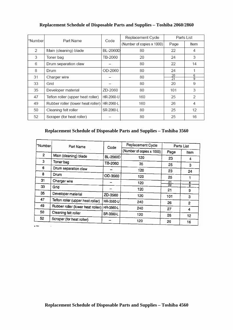
Replacement Schedule of Disposable Parts and Supplies – Toshiba 2060/2860
Replacement Schedule of Disposable Parts and Supplies – Toshiba 3560
Replacement Schedule of Disposable Parts and Supplies – Toshiba 4560

3. A SEP-BY-STEP GUIDE TO PERIODICAL MAINTENANCE AND CLEANING Optical section:

1. Remove screws A and the original glass retaining plate. Remove the original glass and clean it
both sides with window cleaner. Note – do not remove screws B. They are used for correction of image skew and registration of the copy image.
2. Remove screws C. Remove the lens cover D, carefully in the direction E, careful not to break the drive tooth belt of the lens assembly and the carriage drive wire. See figure 5.
5D
A
B
E
C

3. Clean with dry lint free cloth mirrors 1, 2, 3, 4 and 5 as well as the expo-lamp reflector A. 4. Clean with isopropyl alcohol the sliders B and C of the carriage 1 and 2. Note – be careful not to
bend carriage 3, because it is mounted only to the rear side of the copier. Bending will result in copy image skew. See figure 6.
6
43
AB
2 C 5
1
Main body of the machine:

1. Open the front cover of the machine. Push the blue knob in direction A and split the copier in two halves. Remove and clean the waste toner container. Remove the toner container. Remove screw B and unplug terminal C. Gently pull out the developer/image formation module. Place it on a flat, clean surface and cover it with a newspaper so as no light comes in contact with the OPC drum. See figure 7.
7
A
B
C

2. Remove the mirror 6 slit window cover by inserting a finger in place A, pushing a tab in direction B and pulling the cover out in direction C. Clean the glass with window cleaner both sides. See figure 8.
8B A
C

3. Clean mirror 6 with window cleaner. Clean the LED eraser array A and discharge lamps array B with a cloth, soaked with window cleaner. This should remove the tar deposited on them due to the static electricity. This is an important step in improving the image quality. See figure 9.
B
A
6
9

4. Unscrew partially screw A until the transfer/separation corotron can be lifted. Lift it partially and unplug terminal B. Remove the assembly paying attention to the way the corotron is attached in the rear end C.
5. Remove screws D and the registration roller cleaning felt E. Clean the felt with vacuum cleaner from the paper dust. Using a cloth soaked with rubber roller cleaning fluid, rub the registration roller F until you can touch clean rubber. This is an important step, because a dirty roller can cause registration (misalignment) problems with the copy. See figure 10.
10C
F
E
A
D
B
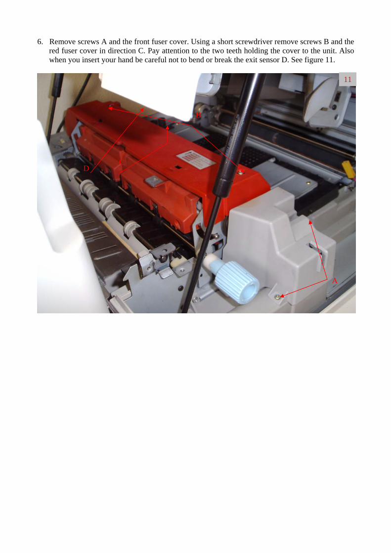
6. Remove screws A and the front fuser cover. Using a short screwdriver remove screws B and the red fuser cover in direction C. Pay attention to the two teeth holding the cover to the unit. Also when you insert your hand be careful not to bend or break the exit sensor D. See figure 11.
11
B
C D
A

7. Unplug the three connectors at the rear end of the fuser unit. Remove screw A and pay attention to the hole it is screwed in. The right one is the circular, not the prolonged. Carefully pull out the fuser unit in direction B. Pay attention the fuser lamp ends, the paper exit sensor and the power supply front switch. See figure 12.
B A
12

8. Remove two screws A and the ozone filter cover. Remove the ozone filter B and clean it both sides with vacuum cleaner. Remove screw C, unplug the two terminals under the transport belt assembly D and remove it in direction E. Clean the area behind the filter with the vacuum cleaner as well as the inside of the machine. Pay special attention to the area around the front and rear corotron terminals and the high voltage assembly F. If there is any developer material on it you may experience all sorts of image quality problems. See figure 13.
13A
B
D
E
F C

9. Turn the machine to 180 degrees. Remove the upper rear cover, by removing the 5 screws that hold it. Located on the cover is a optical fan filter. Clean it carefully with a vacuum cleaner. Clean the whole back side of the machine. See figure 14.
14
Paper feeding section: 10. Remove the two pins that hold the front cover of the machine in direction A. Be
press down too hard the cover, because the hinge assembly is made of plastic andAdvice the operators of the machine to be careful too every time they open the one of the few weak spots of these models. A break will lead to intermediate pato “front cover open “condition detected by the copier. See figure 15.
A A
careful not to it can break.
cover. This is per jams, due
15
11. Open the LCF unit A. Pull out and lift up all the paper trays the copier has. In case of a presence of a paper feed pedestal, there will be 4 or 5 trays (if ADU is not installed). The procedure described here is valid for removing the paper feed units of all 5 slots. Remove the cover B of paper feed unit’s terminal connection with the copier. Unplug the connector too. See figure 16.
B A
16

12. Remove screws A and unplug connector B. Carefully remove the feeder unit in direction C.
See figure 17.
B
A
C
17

CLEANING THE MODULES OF THE MACHINE
Feeder unit: 1. Clean with rubber cleaning fluid and a cloth, the pick up A, feed B and separation C rollers. See figure 18.
C
B
A
18

Transfer/separation corotron assembly: 1. Remove the protective grid A by pushing the 4 tabs. Remove the terminals protective covers B.
Using a vacuum cleaner and a soft brush clean the inside of the assembly, especially the terminals. Be careful not to tear the corotron wires. After you have removed the toner and developer deposits clean thoroughly usin cotton swabs dipped in window cleaner fluid. From my experience this is the only efficient cleaning agent for this type of dirt deposits. See figure 19.
B
A
19

Image formation/developer module: 1. Squeeze the bracket A and remove it in direction B. Lift the main corotron assembly in
direction C and remove it, careful not to scratch the OPC drum. Lift the bracket D and push down bracket E. Carefully separate the imaging unit from the developer unit. Put the imaging unit on a flat clean surface and shade it with a piece of paper. As you know the OPC drum if PHOTO sensitive. See figure 20.
20
C
B
D
E A

Main charger: 1. Push the grid A in direction B and detach it from the hooks at the rear end. Spray the grid with
a window cleaner and brush it both sides. Dry it with a lint free cloth. If there are any fibers left brush them off. This is important for the copy image quality. Using cotton swabs and window cleaner, clean the corotron assembly and the wire itself. See figure 21.
21
A
B

Developer unit: 1. Clean the unit with vacuum cleaner (of course the developer layer on the developer roller
shouldn’t be vacuumed). Don’t turn the unit up side down as the developer material will spill out. Clean underneath the developer roller. If there is too much toner, that is an indicator the developer material is worn and needs to be replaced. Rotate the input gear of the unit in direction A. If there is too much torque needed this is an indicator of a mechanical failure that will be discussed in following articles. However do not allow the operator to use the machine because this will lead to unneeded failures in the main drive assembly. Check if the developer roller spacers B are freely rotating. However too much play is also an indicator for wear. See figure 22.
B A
22

Fusing unit: 1. Remove screws A and the silicone roller cover B. Remove the springs underneath. Pay
attention to the place of the springs. They are not the same type – the one on the geared side of the silicone roller is stiffer than the other. Remove the roller itself. Remove screws C and remove the upper separation fingers assembly. Inspect and replace them if needed. See figure 23.
23B
A
C
C

2. Remove screws A and the upper fuser roller cleaning blade B. Remove screws C and the thermo fuse D. Clean it with acetone. Remove screws E and the plate F. Remove screws G and the two thermistors. Clean them with acetone. See figure 24.
24
F C G E
E B D
E A

3. Remove the clip A and the hand-cranking shaft B. Remove 3 screws C and the lower separation fingers assembly. Clean them with acetone too. See figure 25.
25
A
B
C

4. Remove screws A and the upper paper guide B. Clean the flat surface guides C with acetone. This is important because uneven layers of fused toner can cause image defects, paper jams and wrinkling. See figure 26.
26
A
C
B

5. Clean the silicone roller A it with vacuum cleaner, rubbing carefully its surface. If the dirt doesn’t come off, use a cloth soaked with acetone. After that, soak moderately the roller with silicone oil. Clean the upper B and lower C separation fingers with acetone. Clean the upper fuser roller blade D with acetone. Clean the upper paper guide E with acetone. See figure 27.
27
B
A
E
D
C
4. IMAGE DENSITY ADJUSTMENTS 1. Enter the adjustment mode AJ by holding together numerical buttons 0 and 5 and turning on the
machine. 2. Begin with adjustment of the copy density in the middle position. Make a test copy by pressing
the “Energy saver button”. If the copy is too light or too dark change the value of code 1 (thehigher the value the lighter the copy density). The procedure is the following: enter 1 and pressthe Start button. Change the value and store it by pressing the Interrupt button. Make a test copyand readjust if necessary.
3. Execute the auto exposure auto adjustment procedure – place a couple of white A3 sheets on theoriginal glass and close the platen. Enter code 49 and press the start button. After completionmake a test copy. If necessary change manually the auto exposure density by changing the valuein code 5.

4. Adjust the density of darkest and lightest mode using the same procedure as in 2. The codes are respectively 10 and 9.
5. Adjust the density of the photo exposure – code 14. 6. Exit the AJ mode by pressing the o and 9 buttons or turn off the machine.