torsion and shear stresses in ships · 2013-07-19 · torsion of a thin-walled variable section...
TRANSCRIPT

Torsion and Shear Stresses in Ships
Mohamed Shama
Torsion and Shear Stressesin Ships
123

ISBN 978-3-642-14632-9 e-ISBN 978-3-642-14633-6
DOI 10.1007/978-3-642-14633-6
Springer Heidelberg Dordrecht London New York
Library of Congress Control Number: 2010933503
� Springer-Verlag Berlin Heidelberg 2010
This work is subject to copyright. All rights are reserved, whether the whole or part of the material isconcerned, specifically the rights of translation, reprinting, reuse of illustrations, recitation,broadcasting, reproduction on microfilm or in any other way, and storage in data banks. Duplicationof this publication or parts thereof is permitted only under the provisions of the German Copyright Lawof September 9, 1965, in its current version, and permission for use must always be obtained fromSpringer. Violations are liable to prosecution under the German Copyright Law.
The use of general descriptive names, registered names, trademarks, etc. in this publication does notimply, even in the absence of a specific statement, that such names are exempt from the relevantprotective laws and regulations and therefore free for general use.
Cover design: WMXDesign GmbH
Printed on acid-free paper
Springer is part of Springer Science+Business Media (www.springer.com)
Mohamed ShamaFaculty of EngineeringAlexandria UniversityAlexandria 21544Egypte-mail: [email protected]

To my wifeFor her love, patience, encouragementand support
To my late parentsFor their continuous care andencouragement
To my studentsWhose enthusiasm and hard work haveencouraged me to prepare the coursematerial of this book.
Preface
In the last few decades, much research work was conducted to improve shipstructure analysis and design. Most of the efforts were directed to improve thestrength of hull girder and to use the method of finite element analysis moreefficiently and effectively. Because of the high degree of complexity of shipstructures the interaction between hull girder strength and local strength requirespecial attention. Any structural element of the ship hull girder is subjected toseveral types of stresses including the fabrication and residual stresses. Thestresses induced by hull girder and local loadings include the primary stresses,secondary stresses and tertiary stresses. Local loading comprises tensile, com-pressive, lateral, shear and torsion loadings. This complex system of stresses couldproduce unacceptable deformations and high values of equivalent stresses. Most ofthe methods commonly used for ship structure analysis and design focus on thestresses induced by hull girder bending and shear as well as the stresses induced bylocal lateral loadings.
This book is intended to cover an area of ship structure analysis and design thathas not been exhaustively covered by most published text books on ship structures.
Also, it addresses a very complex subject in the design of ship structure and presentsit in a simple and suitable form for research students and practicing engineers.
In addition it presents the basic concepts of the methods and proceduresrequired to calculate torsion and shear stresses in ship structures.
Moreover, it presents valuable analysis and design material on torsion and shearloading and stresses. The book therefore should be very useful for practicing navalarchitects and students of marine engineering and naval architecture. The book isenhanced with a set of some solved and unsolved problems.
vii

Outline of the Book
The book is composed of three parts: Part I is devoted to Torsion stresses in ships;Part II is concerned with Shear stresses in ships, whereas Part III is specialized tomodeling the aforementioned methodology as separate subjective modules man-aged by a main executive program.
Part I of this book introduces the basic elements of pure torsion of uniformthin-walled open sections are presented. The various cases of local torsion loadingon beam elements are presented. The basic equations of torsion of thin-walledclosed sections, multi-cell box-girders and the general case of combined thin-walled open and closed sections are given.
Torsion of a thin-walled variable section beam subjected to non-uniform torquefor both cases of free warping and constrained warping are considered. Warpingdeformations and flexural warping stresses of thin-walled sections are also pre-sented for different types of loading and end constraints. Warping deformationsand stresses in deck structure of container ships are highlighted.
Solution of the torsion equation for an assumed two distributions of torsionalloading of container ships traveling obliquely in a sea-way is presented. Themethod of calculation is based on using an idealized ship section for calculatingthe sectorial properties of the ship section (principal sectorial area diagram, sec-torial static moment). The position of the shear centre, torsion constant Jt and thewarping constant J(x), the shear and flexural warping stresses are then calculated.The total stress in the deck plating of a container ship due to hull girder bendingand torsional loading is discussed. A numerical example is given to clarify thecalculation procedure.
Chapter 5 gives the basic concepts and calculation procedure of the sectorialproperties of open sections. Chapter 6 gives a general solution of the torsionequation.
Part II of this book presents the basic principles and concepts of shear flow,shear stress, shear deformation and the application of these principles to shipstructure. The shear lag effect in thin-walled structures resulting from the effect ofshear stress on bending stress is presented.
ix

Methods of calculating the distribution of shear flow and stresses over sym-metrical and asymmetrical thin-walled open sections are given.
Shear centre for symmetrical and asymmetrical thin-walled sections isexplained. The distribution of shear stresses over thin-walled single and multi-boxgirders is given. The methods of calculation are explained and supported bynumerical examples.
Methods of calculation of the distribution of shear flow and stress over shipsections are addressed. The methods of calculation are based on the introduction ofa simplified idealization of ship section using an effective thickness for the shellplating and the attached stiffeners. For ship sections having closed boxes, a cor-recting shear flow is introduced to eliminate any torsional distortions induced bythe assumed shear flow distribution.
The method is used to calculate the shear flow distribution over ship sections ofsingle and double deck cargo ships and oil tankers with one and twin longitudinalbulkheads. A method for calculating shear load carried by the side shell platingand longitudinal bulkheads is given. The importance of calculating the distributionof shear stresses over ship sections of the hull girder is emphasized so as todetermine the maximum allowable shearing force for a given ship section.
A damage occurring in any part of the ship structure will cause redistribution ofthe shear and bending stresses over the remaining intact structural members. Somestructural members will be over stressed and others may be lightly stressed. Theshear stress distribution over ship sections experiencing local damages is examinedso as to ensure adequate safety of the overloaded structural members.
Shear loading on ship hull girder is given together with shear force distributionfor alternate hold loading in bulk carriers.
Bulk carriers experience unique problems which result from the particularstructural configuration and loading of these ships (alternate hold loading system).
In bulk carriers, the longitudinal vertical shearing force is carried by the sideshell plating, top wing tanks, and hopper tanks. The side shell, therefore, may carrya high proportion of the longitudinal vertical shearing force. Consequently, shearstresses in the side shell plating may reach unfavorable values. Shear buckling, orhigh values of combined stresses, may occur in some panels in the side shellplating. Adequate measures should be taken, therefore, to prevent the initiation ofinstability and high stresses. The effect of using alternate hold loading system onthe magnitude and distribution of shear loading along ship length is presented.
In order to calculate the shear stress distribution over a typical ship section of abulk carrier, the ship section is idealized by a simplified configuration so as toreduce the laborious calculations associated with shear flow distribution. Theidealized structure should affect neither the magnitude nor the distribution of shearflow distribution around the top wing tanks, hopper tanks, and side shell. Proce-dures for calculating shear flow and stresses in bulk carriers are given in derail.
Part III of this book is specialized to modeling the aforementioned method-ology as separate subjective modules managed by a main executive programnamely PROP�. FORTRAN� is the programming language in which the modulesare written. The program has been written from scratch by Dr. K. A. Hafez,
x Outline of the Book

Department of Naval Architecture and Marine Engineering, Faculty of Engi-neering, Alexandria University, Egypt.
For any arrangement of rectangular cross sections, PROP� calculates theirphysical, sectional, sectorial properties, and the shear center of closed, opened, andcombined cross sections. Also, the interested researcher may use the attachedstandard mathematical subroutines to manipulate the distribution of the sectionaland/or sectorial properties together with their first few derivatives.
The information gathered in this program is expected to be sufficient for thefirst glance without going into more detailed discussion. However, for furtherdetails of the formulations and their associated computer programs, the interestedresearcher may consult the appropriate subjective chapters of this book, or he mayrefer to the listed references at the end of the book. All of the surveyed formu-lations and their associated computer program are computationally fast using thestandard IBM� compatible computers, without any special requirements of thehardware configuration.
One of the main goals of the PROP� program is the easy possibility of additionto and deletion of functional modules as required. The program is not an opti-mization routine but still considered to belong to the preliminary structural designstage without any economical or optimization consideration.
Finally, this part includes three solved examples that surely help in tracing thealgorithm of the PROP� program and understanding the way of input and output.Also, for the interested students and/or researchers a collection of non-solvedproblems is introduced.
Outline of the Book xi

Acknowledgments
I would like to thank Dr. K. A. Hafez, for receiving and correcting the presentationof this book and also for enhancing the value of the material presented herein byadding the source list and output of his computer program in Chapter 12. Also, Iwish to thank all my graduate and undergraduate students who inspired me to writethis book.
xiii
List of Symbols
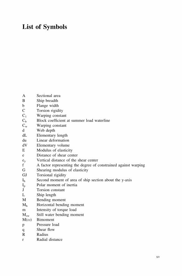
A Sectional areaB Ship breadthb Flange widthC Torsion rigidityC1 Warping constantCb Block coefficient at summer load waterlineCw Warping constantd Web depthdL Elementary lengthdu Linear deformationdV Elementary volumeE Modulus of elasticitye Distance of shear centerey Vertical distance of the shear centerf A factor representing the degree of constrained against warpingG Shearing modulus of elasticityGJ Torsional rigidityIh Second moment of area of ship section about the y-axisIp Polar moment of inertiaJ Torsion constantL Ship lengthM Bending momentMh Horizontal bending momentm Intensity of torque loadMsw Still water bending momentM(x) Bimomentp Pressure loadq Shear flowR Radiusr Radial distance
xv

S Length parameterS(x) Sectorial static momentT TorqueTe Torsional moment at the end of the memberTx Warping torqueTs Saint Venant torquet Thicknesstf Flange thicknesstw Web thicknessu Linear displacementb Angle of deformationc Shear angled Flexural warping coefficientu Angle of twisth Rate of twistm Poisson’s ratior1 Stress at the inner point of the flanger2 Stress at the outer edge of the flangerp Stress at the attached platingrx Flexural warping stresss Shear stressx Sectorial area
xvi List of Symbols
SI Units
International System of Units
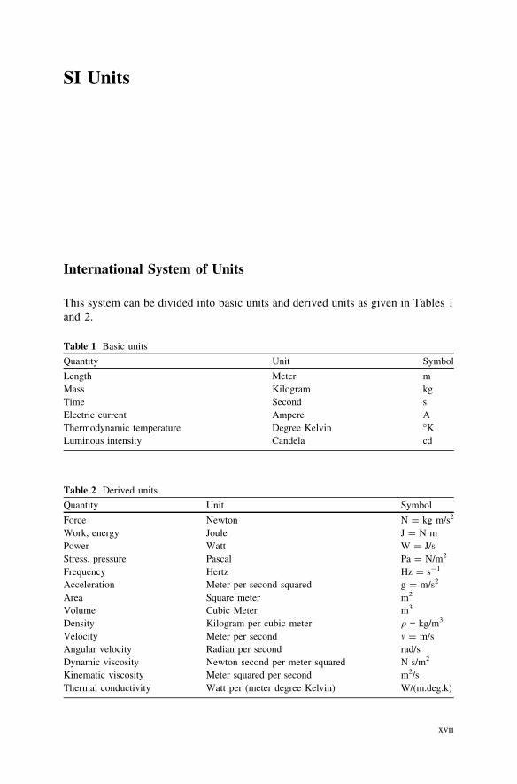
This system can be divided into basic units and derived units as given in Tables 1and 2.
Table 1 Basic units
Quantity Unit Symbol
Length Meter mMass Kilogram kgTime Second sElectric current Ampere AThermodynamic temperature Degree Kelvin �KLuminous intensity Candela cd
Table 2 Derived units
Quantity Unit Symbol
Force Newton N = kg m/s2
Work, energy Joule J = N mPower Watt W = J/sStress, pressure Pascal Pa = N/m2
Frequency Hertz Hz = s-1
Acceleration Meter per second squared g = m/s2
Area Square meter m2
Volume Cubic Meter m3
Density Kilogram per cubic meter q = kg/m3
Velocity Meter per second m = m/sAngular velocity Radian per second rad/sDynamic viscosity Newton second per meter squared N s/m2
Kinematic viscosity Meter squared per second m2/sThermal conductivity Watt per (meter degree Kelvin) W/(m.deg.k)
xvii

Table 3 Summary of thequantities commonly used innaval architecture
Quantity SI unit
Length 0.3048 m1,842 m1,609 m
Area 0.0929 m2
Volume 0.02832 m3
Velocity 0.3048 m/s0.5144 m/s
Standard acceleration 9.8066 m/s2
Mass 0.4536 kg1,016 kg1.016 tonne
Force 4.4482 NPressure, stress 6.8947 kN/m2
15.444 MN/m2
Energy 1.3558 JPower 745.7 WDensity (SW) 0.975 m3/tonne
0.01 MN/m3
Density (FW) 1.0 m3/tonne0.0098 MN/m3
Modulus of elasticity (E) 20.9 GNTPI (SW) 1.025Aw tonne/mTPM 104 AW (N/m)MCT00 (sw) DGML=LðMN m=mÞDisplacement mass force (D) 9964 NDisplacement mass (D) 1.016 tonneWetted surface D = tonne, L = m
Table 4 Power conversion Quantity Common unit SI unit
BHP PB WSHP PS WDHP PD WEHP PE W
Table 5 Multiples and sub-multiples
Prefix Factor Symbol
Tera 1012 TGiga 109 GMega 106 MKilo 103 kMilli 10-3 mMicro 10-6 lNano 10-9 nPico 10-12 pFemto 10-15 fAtto 10-18 a
xviii SI Units
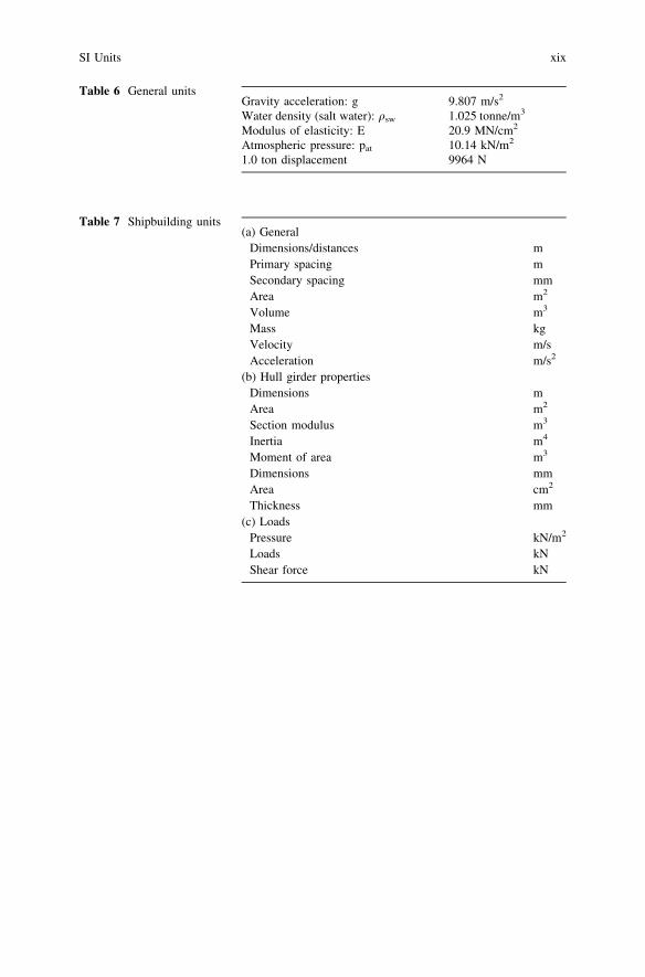
Table 6 General unitsGravity acceleration: gWater density (salt water): qsw
Modulus of elasticity: EAtmospheric pressure: pat
1.0 ton displacement
9.807 m/s2
1.025 tonne/m3
20.9 MN/cm2
10.14 kN/m2
9964 N
Table 7 Shipbuilding units(a) General
Dimensions/distances mPrimary spacing mSecondary spacing mmArea m2
Volume m3
Mass kgVelocity m/sAcceleration m/s2
(b) Hull girder propertiesDimensions mArea m2
Section modulus m3
Inertia m4
Moment of area m3
Dimensions mmArea cm2
Thickness mm(c) Loads
Pressure kN/m2
Loads kNShear force kN
SI Units xix
Contents
Part I Torsion Stresses in Ships
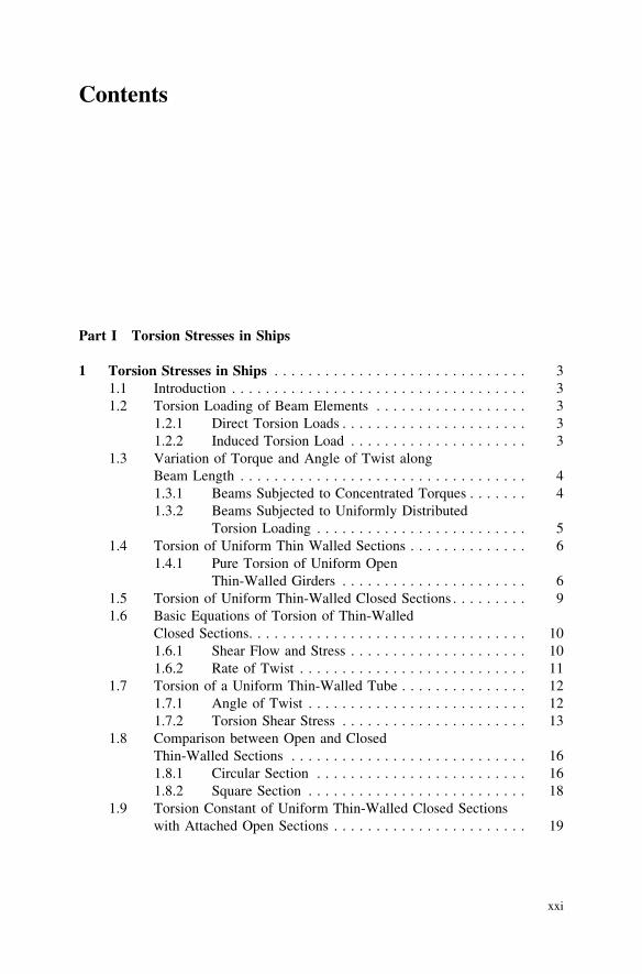
1 Torsion Stresses in Ships . . . . . . . . . . . . . . . . . . . . . . . . . . . . . . 31.1 Introduction . . . . . . . . . . . . . . . . . . . . . . . . . . . . . . . . . . . 31.2 Torsion Loading of Beam Elements . . . . . . . . . . . . . . . . . . 3
1.2.1 Direct Torsion Loads . . . . . . . . . . . . . . . . . . . . . . 31.2.2 Induced Torsion Load . . . . . . . . . . . . . . . . . . . . . 3
1.3 Variation of Torque and Angle of Twist alongBeam Length . . . . . . . . . . . . . . . . . . . . . . . . . . . . . . . . . . 41.3.1 Beams Subjected to Concentrated Torques . . . . . . . 41.3.2 Beams Subjected to Uniformly Distributed
Torsion Loading . . . . . . . . . . . . . . . . . . . . . . . . . 51.4 Torsion of Uniform Thin Walled Sections . . . . . . . . . . . . . . 6
1.4.1 Pure Torsion of Uniform OpenThin-Walled Girders . . . . . . . . . . . . . . . . . . . . . . 6
1.5 Torsion of Uniform Thin-Walled Closed Sections . . . . . . . . . 91.6 Basic Equations of Torsion of Thin-Walled
Closed Sections. . . . . . . . . . . . . . . . . . . . . . . . . . . . . . . . . 101.6.1 Shear Flow and Stress . . . . . . . . . . . . . . . . . . . . . 101.6.2 Rate of Twist . . . . . . . . . . . . . . . . . . . . . . . . . . . 11
1.7 Torsion of a Uniform Thin-Walled Tube . . . . . . . . . . . . . . . 121.7.1 Angle of Twist . . . . . . . . . . . . . . . . . . . . . . . . . . 121.7.2 Torsion Shear Stress . . . . . . . . . . . . . . . . . . . . . . 13
1.8 Comparison between Open and ClosedThin-Walled Sections . . . . . . . . . . . . . . . . . . . . . . . . . . . . 161.8.1 Circular Section . . . . . . . . . . . . . . . . . . . . . . . . . 161.8.2 Square Section . . . . . . . . . . . . . . . . . . . . . . . . . . 18
1.9 Torsion Constant of Uniform Thin-Walled Closed Sectionswith Attached Open Sections . . . . . . . . . . . . . . . . . . . . . . . 19
xxi
xxii Contents
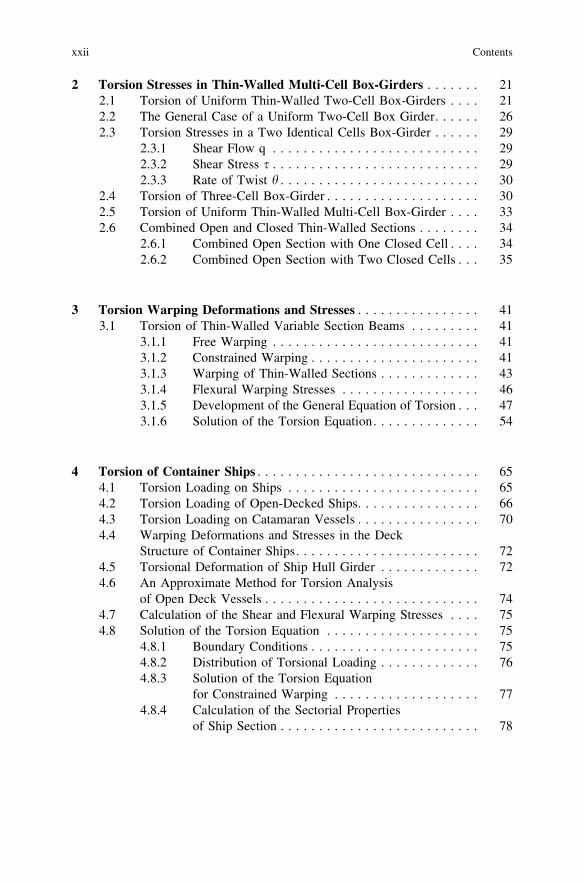
2 Torsion Stresses in Thin-Walled Multi-Cell Box-Girders . . . . . . . 212.1 Torsion of Uniform Thin-Walled Two-Cell Box-Girders . . . . 212.2 The General Case of a Uniform Two-Cell Box Girder. . . . . . 262.3 Torsion Stresses in a Two Identical Cells Box-Girder . . . . . . 29
2.3.1 Shear Flow q . . . . . . . . . . . . . . . . . . . . . . . . . . . 292.3.2 Shear Stress s . . . . . . . . . . . . . . . . . . . . . . . . . . . 292.3.3 Rate of Twist h . . . . . . . . . . . . . . . . . . . . . . . . . . 30
2.4 Torsion of Three-Cell Box-Girder . . . . . . . . . . . . . . . . . . . . 302.5 Torsion of Uniform Thin-Walled Multi-Cell Box-Girder . . . . 332.6 Combined Open and Closed Thin-Walled Sections . . . . . . . . 34
2.6.1 Combined Open Section with One Closed Cell . . . . 342.6.2 Combined Open Section with Two Closed Cells . . . 35
3 Torsion Warping Deformations and Stresses . . . . . . . . . . . . . . . . 413.1 Torsion of Thin-Walled Variable Section Beams . . . . . . . . . 41
3.1.1 Free Warping . . . . . . . . . . . . . . . . . . . . . . . . . . . 413.1.2 Constrained Warping . . . . . . . . . . . . . . . . . . . . . . 413.1.3 Warping of Thin-Walled Sections . . . . . . . . . . . . . 433.1.4 Flexural Warping Stresses . . . . . . . . . . . . . . . . . . 463.1.5 Development of the General Equation of Torsion . . . 473.1.6 Solution of the Torsion Equation. . . . . . . . . . . . . . 54
4 Torsion of Container Ships . . . . . . . . . . . . . . . . . . . . . . . . . . . . . 654.1 Torsion Loading on Ships . . . . . . . . . . . . . . . . . . . . . . . . . 654.2 Torsion Loading of Open-Decked Ships. . . . . . . . . . . . . . . . 664.3 Torsion Loading on Catamaran Vessels . . . . . . . . . . . . . . . . 704.4 Warping Deformations and Stresses in the Deck
Structure of Container Ships. . . . . . . . . . . . . . . . . . . . . . . . 724.5 Torsional Deformation of Ship Hull Girder . . . . . . . . . . . . . 724.6 An Approximate Method for Torsion Analysis
of Open Deck Vessels . . . . . . . . . . . . . . . . . . . . . . . . . . . . 744.7 Calculation of the Shear and Flexural Warping Stresses . . . . 754.8 Solution of the Torsion Equation . . . . . . . . . . . . . . . . . . . . 75
4.8.1 Boundary Conditions . . . . . . . . . . . . . . . . . . . . . . 754.8.2 Distribution of Torsional Loading . . . . . . . . . . . . . 764.8.3 Solution of the Torsion Equation
for Constrained Warping . . . . . . . . . . . . . . . . . . . 774.8.4 Calculation of the Sectorial Properties
of Ship Section . . . . . . . . . . . . . . . . . . . . . . . . . . 78

4.9 Total Stress in the Deck Plating of Container Ships due toHull Girder Bending and Torsional Loading. . . . . . . . . . . . . 854.9.1 Hull Girder Stresses due to Vertical Bending . . . . . 864.9.2 Horizontal Hull Girder Bending Stresses . . . . . . . . 874.9.3 Local Stresses . . . . . . . . . . . . . . . . . . . . . . . . . . . 874.9.4 Flexural Warping Stresses . . . . . . . . . . . . . . . . . . 884.9.5 Total Stress Over the Deck Plating . . . . . . . . . . . . 89
5 Sectorial Properties of Thin-Walled Open Sections . . . . . . . . . . . 915.1 Introduction . . . . . . . . . . . . . . . . . . . . . . . . . . . . . . . . . . . 915.2 Sectorial Properties of Thin-Walled Sections . . . . . . . . . . . . 91
5.2.1 Principal Sectorial Propertiesof Thin-Walled Sections. . . . . . . . . . . . . . . . . . . . 93
5.2.2 Position of the Shear Center . . . . . . . . . . . . . . . . . 945.2.3 Sectorial Area Diagram . . . . . . . . . . . . . . . . . . . . 955.2.4 Procedure of Calculation . . . . . . . . . . . . . . . . . . . 96
5.3 Applications to Some Typical Sections . . . . . . . . . . . . . . . . 965.3.1 Sectorial Properties for Thin-Walled
Sections Free to Warp . . . . . . . . . . . . . . . . . . . . . 965.4 Sectorial Properties for a Thin-Walled Section with
an Enforced Axis of Rotation . . . . . . . . . . . . . . . . . . . . . . . 1015.4.1 A thin-Walled T-Section with an Enforced
Axis of Rotation . . . . . . . . . . . . . . . . . . . . . . . . . 1015.4.2 Enforced Center of Rotation for a
Thin-Walled Angle Section. . . . . . . . . . . . . . . . . . 1025.4.3 Enforced Center of Rotation at a Point C
on the Opposite Side of a Thin-WalledAsymmetrical Fabricated Section. . . . . . . . . . . . . . 102
6 General solution of the torsion equation . . . . . . . . . . . . . . . . . . . 105
Part II Shear Loading and Stresses in Ships
7 Shear Stresses in Thin-Walled Structures . . . . . . . . . . . . . . . . . . 1117.1 Basic Principles . . . . . . . . . . . . . . . . . . . . . . . . . . . . . . . . 1117.2 Shear Stresses in Beams due to Bending . . . . . . . . . . . . . . . 111
7.2.1 Solid Beams . . . . . . . . . . . . . . . . . . . . . . . . . . . . 1117.2.2 Average Shear Stress . . . . . . . . . . . . . . . . . . . . . . 1147.2.3 Shear Flow and Stress in Thin-Walled Sections . . . 115
7.3 Shear Centre. . . . . . . . . . . . . . . . . . . . . . . . . . . . . . . . . . . 124
Contents xxiii

xxiv Contents
7.4 Shear Deflection . . . . . . . . . . . . . . . . . . . . . . . . . . . . . . . . 1277.4.1 Shear Deformation. . . . . . . . . . . . . . . . . . . . . . . . 129
7.5 Shear Lag. . . . . . . . . . . . . . . . . . . . . . . . . . . . . . . . . . . . . 130
8 Shear Flow and Stresses in Thin-Walled Box-Girders . . . . . . . . . 1338.1 Single Cell Box-Girder . . . . . . . . . . . . . . . . . . . . . . . . . . . 1338.2 Shear Flow in Asymmetrical Closed Box-Girders
Subjected to a Vertical Shear Force F . . . . . . . . . . . . . . . . . 1358.3 Shear Stresses in Thin-Walled Two-Cell Box-Girders . . . . . . 1428.4 Calculation of the Correcting Shear Flow for 3-Cell
Box-Girders Subjected to Shear Load . . . . . . . . . . . . . . . . . 146
9 Shear Flow and Stresses in Ships . . . . . . . . . . . . . . . . . . . . . . . . 1499.1 Introduction . . . . . . . . . . . . . . . . . . . . . . . . . . . . . . . . . . . 1499.2 Procedure of Calculation of Shear Flow Distribution . . . . . . . 149
9.2.1 Ship Section Idealization . . . . . . . . . . . . . . . . . . . 1499.3 Determination of the Effective Thickness. . . . . . . . . . . . . . . 1579.4 Shear Flow Calculation . . . . . . . . . . . . . . . . . . . . . . . . . . . 157
9.4.1 Procedure of Calculation of Shear Flow Distribution 1589.4.2 Shear Flow Distribution over a Ship Section
of a Two-deck Cargo Ship . . . . . . . . . . . . . . . . . . 1609.5 Calculation of Shear Stress Distribution . . . . . . . . . . . . . . . . 161
9.5.1 Equivalent Stress . . . . . . . . . . . . . . . . . . . . . . . . . 1619.6 Calculation of Shear Stress Distribution over a Ship Section . . . 162
9.6.1 Calculation of Shear Flow Distributionover a Twin DeckCargo Ship . . . . . . . . . . . . . . . . 163
9.7 Shear Flow Distribution over a Catamaran Section . . . . . . . . 164
10 Calculation of Shear Stresses in Tankers Subjectedto Longitudinal Vertical Shear Forces . . . . . . . . . . . . . . . . . . . . . 16710.1 Coastal Tankers Having One Longitudinal Bulkhead . . . . . . . 16710.2 Calculation of Shear Flow Distribution for
Twin Longitudinal Bulkhead Tankers . . . . . . . . . . . . . . . . . 16910.3 Shear Load Carried by Longitudinal Bulkheads
and Side Shell Plating . . . . . . . . . . . . . . . . . . . . . . . . . . . . 17310.3.1 Sea-Going Tankers with Two Longitudinal
Bulkheads. . . . . . . . . . . . . . . . . . . . . . . . . . . . . . 17310.3.2 Coastal Tankers with One Longitudinal Bulkhead. . . 175
10.4 Shear Flow Distribution Over a Ship Section of an Oil TankerExperiencing a Local Damage in the Shell Platingor Longitudinal Bulkhead. . . . . . . . . . . . . . . . . . . . . . . . . . 17610.4.1 Introduction . . . . . . . . . . . . . . . . . . . . . . . . . . . . 176
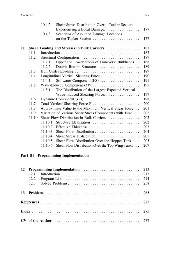
10.4.2 Shear Stress Distribution Over a Tanker SectionExperiencing a Local Damage. . . . . . . . . . . . . . . . 177
10.4.3 Scenarios of Assumed Damage Locationson the Tanker Section . . . . . . . . . . . . . . . . . . . . . 177
11 Shear Loading and Stresses in Bulk Carriers . . . . . . . . . . . . . . . 18711.1 Introduction . . . . . . . . . . . . . . . . . . . . . . . . . . . . . . . . . . . 18711.2 Structural Configuration. . . . . . . . . . . . . . . . . . . . . . . . . . . 187
11.2.1 Upper and Lower Stools of Transverse Bulkheads . . 18811.2.2 Double Bottom Structure . . . . . . . . . . . . . . . . . . . 189
11.3 Hull Girder Loading . . . . . . . . . . . . . . . . . . . . . . . . . . . . . 18911.4 Longitudinal Vertical Shearing Force . . . . . . . . . . . . . . . . . 190
11.4.1 Stillwater Component (FS) . . . . . . . . . . . . . . . . . . 19111.5 Wave-Induced Component (FW) . . . . . . . . . . . . . . . . . . . . . 195
11.5.1 The Distribution of the Largest Expected VerticalWave-Induced Shearing Force. . . . . . . . . . . . . . . . 197
11.6 Dynamic Component (FD) . . . . . . . . . . . . . . . . . . . . . . . . . 19811.7 Total Vertical Shearing Force F . . . . . . . . . . . . . . . . . . . . . 20011.8 Approximate Value to the Maximum Vertical Shear Force . . 20111.9 Variation of Various Shear Stress Components with Time . . . 20211.10 Shear Flow Distribution in Bulk Carriers . . . . . . . . . . . . . . . 202
11.10.1 Structure Idealization . . . . . . . . . . . . . . . . . . . . . . 20211.10.2 Effective Thickness . . . . . . . . . . . . . . . . . . . . . . . 20311.10.3 Shear Flow Distribution . . . . . . . . . . . . . . . . . . . . 20411.10.4 Shear Stress Distribution . . . . . . . . . . . . . . . . . . . 20511.10.5 Shear Flow Distribution Over the Hopper Tank . . . 20511.10.6 Shear Flow Distribution Over the Top Wing Tanks. . . 207
Part III Programming Implementation
12 Programming Implementation . . . . . . . . . . . . . . . . . . . . . . . . . . 21312.1 Introduction . . . . . . . . . . . . . . . . . . . . . . . . . . . . . . . . . . . 21312.2 Program List. . . . . . . . . . . . . . . . . . . . . . . . . . . . . . . . . . . 21412.3 Solved Problems . . . . . . . . . . . . . . . . . . . . . . . . . . . . . . . . 258
13 Problems . . . . . . . . . . . . . . . . . . . . . . . . . . . . . . . . . . . . . . . . . . 265
References . . . . . . . . . . . . . . . . . . . . . . . . . . . . . . . . . . . . . . . . . . . . 273
Index . . . . . . . . . . . . . . . . . . . . . . . . . . . . . . . . . . . . . . . . . . . . . . . . 275
CV of the Author . . . . . . . . . . . . . . . . . . . . . . . . . . . . . . . . . . . . . . . 277
Contents xxv
Part ITorsion Stresses in Ships
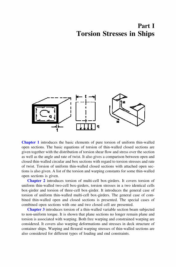
Chapter 1 introduces the basic elements of pure torsion of uniform thin-walledopen sections. The basic equations of torsion of thin-walled closed sections aregiven together with the distribution of torsion shear flow and stress over the sectionas well as the angle and rate of twist. It also gives a comparison between open andclosed thin-walled circular and box sections with regard to torsion stresses and rateof twist. Torsion of uniform thin-walled closed sections with attached open sec-tions is also given. A list of the torsion and warping constants for some thin-walledopen sections is given.
Chapter 2 introduces torsion of multi-cell box-girders. It covers torsion ofuniform thin-walled two-cell box-girders, torsion stresses in a two identical cellsbox-girder and torsion of three-cell box-girder. It introduces the general case oftorsion of uniform thin-walled multi-cell box-girders. The general case of com-bined thin-walled open and closed sections is presented. The special cases ofcombined open sections with one and two closed cell are presented.
Chapter 3 introduces torsion of a thin-walled variable section beam subjectedto non-uniform torque. It is shown that plane sections no longer remain plane andtorsion is associated with warping. Both free warping and constrained warping areconsidered. It covers also warping deformations and stresses in deck structure ofcontainer ships. Warping and flexural warping stresses of thin-walled sections arealso considered for different types of loading and end constraints.

Chapter 4 introduces the definitions and differences between St. Venant tor-sion, warping torsion and the bi-moment. The main elements of torsion of open-decked ships are presented. Hull girder torsion loading and the various cases oflocal torsion loading on beam elements are considered.
Torsion of container ships traveling obliquely in a sea-may is highlighted.Solution of the torsion equation for assumed two distributions of torsional loadingare presented. The method of calculation is based on a simplified idealization ofthe ship section, calculation of the sectorial properties of the ship section (principalsectorial area diagram, sectorial static moment), position of shear centre, torsionconstant Jt and the warping constant J(x). The calculation of the shear and flexuralwarping stresses are carried out for two cases of boundary conditions, free end, i.e.free warping and constrained end, i.e. constrained warping. The total stress in thedeck plating of a container ship due to hull girder bending and torsional loading ispresented. A numerical example is given for a container ship to illustrate andclarify the calculation procedure.
Chapter 5 presents the calculation procedure of the sectorial properties ofopen sections.
Chapter 6 presents a general procedure for the solution of the torsion equation.
2 Torsion Stresses in Ships

Chapter 1Torsion Stresses in Ships
1.1 Introduction
The torsion analysis is devoted to determining the stress distribution in twistedsingle-span or continuous numbers with solid, thin-walled open or closed crosssections.
A prismatic member resists a twisting moment in two ways.
1. By producing a circulatory shear flow in the cross section.2. By inducing sheer stresses resulting from the change in axial stresses.
The first is called St. Venant torsion and the second is called warping torsion orflexural twist. A flexural twist causes always some bending moments in a structurei.e., a pair or more of bending moments. These are called ‘‘Bi-moment’’.
1.2 Torsion Loading of Beam Elements
1.2.1 Direct Torsion Loads
• Concentrated torsion load, see Fig. 1.1.• Uniformly distributed torsion loading, see Fig. 1.2.• Linearly distributed torsion loading, see Fig. 1.3.
1.2.2 Induced Torsion Load
Torsion loads may be induced by lateral forces acting at an offset distance from theshear center of the beam section. For the thin-walled channel section shown in
M. Shama, Torsion and Shear Stresses in Ships,DOI: 10.1007/978-3-642-14633-6_1, � Springer-Verlag Berlin Heidelberg 2010
3

Fig. 1.4, the shear center of the section is located at a distance e from the web ofthe section. The induced concentrated torque is given by
T ¼ F � e
where F = lateral concentrated force; e = distance of shear center from the webof the section; T = induced concentrated torque.
1.3 Variation of Torque and Angle of Twist along Beam Length
1.3.1 Beams Subjected to Concentrated Torques
1.3.1.1 Concentrated Torque at End of Beam
The distribution of torque loading and the variation of angle of twist along a can-tilever beam subjected to a concentrated torque at its free end are shown in Fig. 1.5.
Fig. 1.2 Uniformly distrib-uted torsion loading
Fig. 1.3 Linearly distributedtorsion loading
Fig. 1.4 Concentrated tor-que induced by the lateralforce F
Fig. 1.1 Concentrated tor-que at the free end of thebeam
4 1 Torsion Stresses in Ships
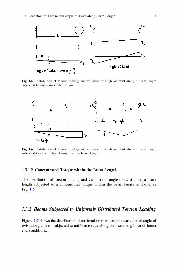
1.3.1.2 Concentrated Torque within the Beam Length
The distribution of torsion loading and variation of angle of twist along a beamlength subjected to a concentrated torque within the beam length is shown inFig. 1.6.
1.3.2 Beams Subjected to Uniformly Distributed Torsion Loading
Figure 1.7 shows the distribution of torsional moment and the variation of angle oftwist along a beam subjected to uniform torque along the beam length for differentend conditions.
Fig. 1.5 Distribution of torsion loading and variation of angle of twist along a beam lengthsubjected to end concentrated torque
Fig. 1.6 Distribution of torsion loading and variation of angle of twist along a beam lengthsubjected to a concentrated torque within beam length
1.3 Variation of Torque and Angle of Twist along Beam Length 5
1.4 Torsion of Uniform Thin Walled Sections
1.4.1 Pure Torsion of Uniform Open Thin-Walled Girders
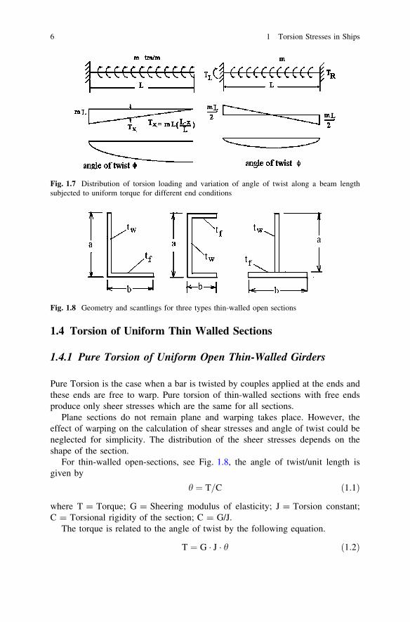
Pure Torsion is the case when a bar is twisted by couples applied at the ends andthese ends are free to warp. Pure torsion of thin-walled sections with free endsproduce only sheer stresses which are the same for all sections.
Plane sections do not remain plane and warping takes place. However, theeffect of warping on the calculation of shear stresses and angle of twist could beneglected for simplicity. The distribution of the sheer stresses depends on theshape of the section.
For thin-walled open-sections, see Fig. 1.8, the angle of twist/unit length isgiven by
h ¼ T=C ð1:1Þ
where T = Torque; G = Sheering modulus of elasticity; J = Torsion constant;C = Torsional rigidity of the section; C = G/J.
The torque is related to the angle of twist by the following equation.
T ¼ G � J � h ð1:2Þ
Fig. 1.7 Distribution of torsion loading and variation of angle of twist along a beam lengthsubjected to uniform torque for different end conditions
Fig. 1.8 Geometry and scantlings for three types thin-walled open sections
6 1 Torsion Stresses in Ships
1.4.1.1 Torsion Constant
The torsion constant J of an open thin-walled section is given by
J ¼X
sit3i
�3
� �
where s = a and b, see Fig. 1.8.For the angle section shown in Fig. 1.8.
J ¼X
sit3i
�3
� �¼ at3
w
�3þ bt3
f
�3
For the channel section
J ¼X
sit3i
�3
� �¼ at3
w
�3þ 2bt3
f
�3
For the T section
J ¼X
sit3i
�3
� �¼ at3
w
�3þ bt3
f
�3
The torsion and warping constants for three thin-walled open sections are givenin Table 1.1.
1.4.1.2 Distribution of Torsion Shear Flow and Stress Overa Thin-Walled Open Section
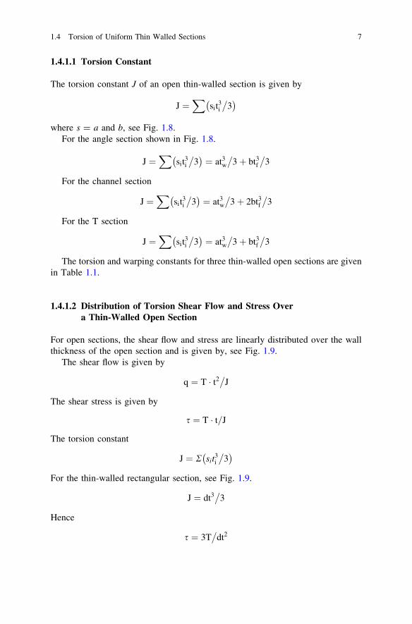
For open sections, the shear flow and stress are linearly distributed over the wallthickness of the open section and is given by, see Fig. 1.9.
The shear flow is given by
q ¼ T � t2�
J
The shear stress is given by
s ¼ T � t=J
The torsion constant
J ¼ R sit3i
�3
� �
For the thin-walled rectangular section, see Fig. 1.9.
J ¼ dt3�
3
Hence
s ¼ 3T�
dt2
1.4 Torsion of Uniform Thin Walled Sections 7

For the thin-walled angle section, the torsion stress in the flange is given by
sf ¼ T � tf=J
The torsion stress in the web of the section is given by
sw ¼ T � tw=J
Fig. 1.9 Shear flow distribu-tion over thin-walled opensections
Table 1.1 Torsion and warping constants for some thin-walled open sections
O = shear center J = torsion constant Cw = warping constant
J ¼2bt3
f þ ht3w
3 If tf = tw = t:
Cw ¼tf h2b3
24J ¼ t3
3ð2bþ hÞ
e ¼ hb3
1
b21 þ b3
2If tf = tw = t;
J ¼b1 þ b2ð Þt3
f þ ht3w
3J ¼ t3
3ðb1 þ b2 þ hÞ
Cw ¼tf h2
12b3
1b32
b31 þ b3
2
e ¼ 3b2tf6btf þ htw
If tf = tw = t:
J ¼2bt3
f þ ht3w
3e ¼ 3b2
6bþ h
Cw ¼tf b3h2
123btf þ 2htw
6btf þ htwJ ¼ t3
3ð2bþ hÞ
Cw ¼tb3h2
123bþ 2h
6bþ h
8 1 Torsion Stresses in Ships

The angle of twist is given by
u ¼ TL=GJ
where G = shear modulus and is given by
G ¼ E=2 1þ mð Þ
1.5 Torsion of Uniform Thin-Walled Closed Sections
Letq = shear flow in t/m over the periphery of the thin-walled closed section.
Then
T ¼I
q � ds � r
¼ qI
rds
¼ 2qI
dA
¼ 2qA
where r�ds = 2 sectional area, see Fig. 1.10; A = enclosed area of the section.Hence
T ¼ 2 � q � A
and
q ¼ T=2A
Thus, when a torque T is applied to a closed thin-walled uniform member, theshear stress is given by
s ¼ q=t ¼ T=2At
Fig. 1.10 Shear flow over aclosed thin-walled section
1.4 Torsion of Uniform Thin Walled Sections 9

The rate of twist, h, is calculated by equating the internal energy to the externalwork, i.e.,
1=2 � T � h ¼I
s2�
2G � dV
But dV = t�ds for a unit length of the member and
s ¼ T=2At
Hence
h ¼ du=dL ¼ 1�
4A2G �I
Tds=t ¼ 1=2AG �I
qds=t
In general
h ¼ T=GJt
where Jt = torsion constant of the thin-walled closed section and is given by
Jt ¼ 4A2
�Ids=t
1.6 Basic Equations of Torsion of Thin-Walled Closed Sections
1.6.1 Shear Flow and Stress
Letq = shear flow in t/m around the periphery of the section, see Fig. 1.11.
Hence the shear flow is given by
q ¼ T=2At
Fig. 1.11 Shear stress over the thickness of a closed thin-walled section
10 1 Torsion Stresses in Ships