torrance park & ride regional terminal
TRANSCRIPT
Torrance Park & Ride
Regional Terminal
Master Plan Report-DraftMarch 05, 2012

Table of Contents
Chapter 1
Chapter 2
Chapter 3
Chapter 4
Executive Summary
Basis for Planning
Space Needs Program
Planning Parameters (Not included in March 5th Draft)
Sustainability Goals (Not included in March 5th Draft)
Design Charrette (Not included in March 5th Draft)
Master Plan
Cost Estimate (Not included in March 5th Draft)
Appendix (Not included in March 5th Draft)
Chapter 5
Chapter 6
Chapter 7
Chapter 8

1234
7
5
8
9
12
14
19
22
24
15
23
6
27
30
31
32
11
21
25
05
105
110
110
405
TORRANCE
LOMITA
PALOSVERDES
HARBORCITY
LOANG
LOSANGELES
GARDENA
HAWTHORNE 1
2
5
7
9
Arl
ing
ton
Ave
o Blvd
Skypark Dr.
Mad
iso
n S
t
Plaza Del Amo
Lomita Blvd
Cab
rillo
Ave
Van
Nes
s A
ve
An
za A
ve
Carson St
An
za A
ve
Fig
uer
oa
St
Fig
uer
oa
St
Gardena Blvd
182nd St
Ave
Ing
lew
oo
d A
ve
Prai
rie
Ave
rbo
nn
e A
ve
Mad
ron
a A
ve
Sepulveda Blvd
Artesia Blvd
Rosecrans Ave
Marine Ave
Manhattan Beach Blvd
El Segundo Blvd E
135th St
Redondo Beach Blvd
Haw
tho
rne
Blv
d
190th St
Verm
on
t A
ve
Nor
man
die
Ave
Wes
tern
Ave
Torrance Blvd
Cre
nsh
aw B
lvd
TorranceAirport
HarborFreewayStation
Del AmoMall(See
SystemMap Page)
Chapter 1: Executive Summary

The City of Torrance, CA currently operates eight bus routes running through the City and reaching into neighboring Los Angeles communities in all directions. The City had identifi ed the need to provide a centralized transfer location where patrons may access Torrance Transit as well as other neighboring transit services. A 15-acre property was pur-chased at 465 Crenshaw Boulevard for this purpose.
The Torrance Transit Park & Ride Regional Terminal is expect-ed to be a state of the art, regional intermodal transit hub serving the South Bay/Los Angeles region opening in sum-mer 2014. It shall improve transit operations at this location as well as to provide comfort, convenience and safety for transit patrons. Additionally this is an economic develop-ment project, designed to encourage transit oriented de-velopment and additional amenities for the ridership and community.
Introduction
LOS ANGELES COMPILATION TRANSIT MAP - BUS AND RAIL
City of Torrance
1.01 1.02

Scope of Services
The City of Torrance commissioned RNL and it’s consultants to develop Site Planning and 30% Design - Bridging Documents for the Measure R Project P4 - Torrance Park and Ride Regional Terminal Project - FEAP 764. This project includes master planning of the entire 15-acre site to determine the most appropriate location of the Transit Center to balance all of the required uses, potential uses, circulation, expandability. The 30% Design-Bridg-ing documents include the development of Advanced Conceptual Engineering (ACE) documents that are inclusive enough to be the solicitation documents for a “Design-Build” sealed bid contract.
The scope of master planning work, organized into four phases, allowed a methodical ap-proach to establish future space requirements, develop a site master plan, determine the transit building architecture, space arrangement and engineered systems, incorporate sus-tainable building and site design, and provide cost estimate services for project budgeting. A description of the major work elements of each phase follows.
Phase I - Information GatheringThis phase initiates the information gathering necessary to allow the project to embody the goals of the City of Torrance with the planning and overall development of the site. Sub-tasks involve collection, receipt and acknowledgement of electronic media and data; review boundary, topographic, underground utility surveys, and geotechnical reports,; perform soil borings of areas of excavation for structure or infrastructure; engage key staff members from the City in Programming interviews to determine function and size alloca-tion for site and building elements. The Information Gathering stage set the stage for the development of initial site affi nity diagrams that were used to kick-off Phase II.
Phase II - Design CharretteOver three days, a single design charrette was conducted between RNL, the Civil engi-neer (Psomas), sustainability consultant (Ambient Energy) and the City. The purpose of the charrette was to focus on arranging the physical layout of the site in an interactive atmosphere where the design team could react to and address the City’s comments and concerns. Additionally, the charrette involved an Eco-Charrette to set Project sustainabil-ity goals and review the LEED checklist. The result of the design charrette was a series of nine conceptual design sketches that were later developed into one focus site layout. This single site concept diagram became the source of the further developed Transit Center ACE documents and master plan.
Phase III - Master PlanningThe purpose and objective of the Master Planning Phase was to develop a conceptual layout of the transit center and transit site and to address the programmatic and facility needs developed during phases I and II. The Master Planning concentrated on developing a conceptual site plan that addressed the functional, operational and expansion require-ments of the Transit Center site and to provide usable TOD (Transit Oriented Development) parcels.
Phase IV - BudgetingIn response to the Master Plan, the RNL consultant team developed order-of-magnitude cost estimates for the proposed improvements, new construction and TOD parceling. Ad-ditionally, a total project budget was prepared that delineates both hard and soft costs, the costs for construction and design.
1.03 1.04
SITESITE

Report Overview:
This Master Plan Study consists of eight chapters. Below is a brief description of each chapter.
Chapter 1: Executive Summary - describes the background of the project, defi nes the scope of work within each of the phases, and gives an overview of the report.
Chapter 2: Basis for Planning - provides a summary of the more qualitative planning issues that were noted during Programming interviews with the client. Each summary includes a descrip-tion of the categories responsibilities, space needs, planning issues, general staffi ng information, and important adjacencies to other program elements. All of this is compiled for consideration during future planning and design efforts.
Chapter 3: Space Needs Program - presents general list of space requirements for the proposed section in the master plan. They will become further developed into detailed assessments based on current and future needs and identifi ed by their quantity, area, and signifi cance to design.
Chapter 4: Planning Parameters - identifi es the conditions of the overall site and context while analyzing current zoning and code restrictions.
Chapter 5: Sustainable Goals - is a guideline of possible LEED points that may be achieved for this project.
Chapter 6: Design Approach - is an exhibit of the results of the charrette week during which nine possible concepts were explored.
Chapter 7: Master Plan - presents the Final Plan developed during the planning process. The Fi-nal Master Plan develop by the RNL Design Team was created from multiple schemes prepared during the original on-site charrette and subsequent working sessions with the City.
Chapter 8: Cost Estimating and Project Budgeting - provides an order-of-magnitude cost es-timate for the proposed improvements and new construction of the Transit Center, transit site and Transit Oriented Development parcels. The estimate includes total Project Budget that delineates the costs for construction and design.
Appendix: Includes copies of supporting documentation developed through the planning process.
VICINITY MAP - TORRANCE TRANSIT PARK & RIDE REGIONAL CENTER
CR
ENSH
AW
BLV
D.
RAIL ROW
MARICOPA ST.
DEL AMO BLVD.
SITE
DOMINGUEZ ST.
W. 208th ST.ALASKA AVE.
1.05 1.06

1234
7
5
8
9
12
14
19
22
24
15
23
6
27
30
31
32
11
21
25
05
105
110
110
405
TORRANCE
LOMITA
PALOSVERDES
HARBORCITY
LOANG
LOSANGELES
GARDENA
HAWTHORNE 1
2
5
7
9
Arl
ing
ton
Ave
o Blvd
Skypark Dr.
Mad
iso
n S
t
Plaza Del Amo
Lomita Blvd
Cab
rillo
Ave
Van
Nes
s A
ve
An
za A
ve
Carson St
An
za A
ve
Fig
uer
oa
St
Fig
uer
oa
St
Gardena Blvd
182nd St
Ave
Ing
lew
oo
d A
ve
Prai
rie
Ave
rbo
nn
e A
ve
Mad
ron
a A
ve
Sepulveda Blvd
Artesia Blvd
Rosecrans Ave
Marine Ave
Manhattan Beach Blvd
El Segundo Blvd E
135th St
Redondo Beach Blvd
Haw
tho
rne
Blv
d
190th St
Verm
on
t A
ve
Nor
man
die
Ave
Wes
tern
Ave
Torrance Blvd
Cre
nsh
aw B
lvd
TorranceAirport
HarborFreewayStation
Del AmoMall(See
SystemMap Page)
Chapter 2: Basis for Planning

BASIS FOR PLANNINGThis chapter provides a breakdown of each category in the facility and site. This chapter is used as a basis for planning spacial and operational needs. Generally, each category is summarized through characteristics such as function, adjacencies, hours of operation, staff organization, etc.
The category organization is as follows:
PUBLIC SPACE
TENANT SPACE
OPERATIONAL SPACE
TRANSIT ORIENTED DEVELOPMENT
2.022.01

OPERATIONS
EMPLOYEE PARKING
BUS
BERTHS
BUSES
CARS
PEDESTRIANS
SECURITY
RETAIL
TRANSIT STORE
VISITOR PARKING
FUELING/CHARGING
STATION
TERMINAL/PLAZAS
TRANSIT SITE AFFINITY DIAGRAM 2.042.03

PUBLIC SPACE
LOBBY
TENANT
TRANSITSTORE TVM’s
MERCHANDISE
SALESCOUNTER VOLUNTEER
STATION
REST-ROOMS
*could be shared with
TENANT spaces
MEN
FAMILY
WOMEN
MERCHSTORAGE
PUBLIC SPACE
The Transit Store is located in close proximity to the bus terminal circulation route. Future build-out for extra service lines at the transit store (Volunteer Station) and extra waiting space in the Lobby are planned.
IMPORTANT ADJACENCIES
FUNCTION OF CATEGORYThis category serves as the public space for transit related information and purchases and represents the gateway between the transit and tenant spaces.
HOURS OF OPERATIONThe operation hours of the Transit Store will be tailored to the needs of the customers. Af-ter hour Ticket Vending Machines (TVM’s) are available during standard terminal operating hours. The Lobby will be open during standard terminal operating hours.
Up to two full time workers in the transit store. The Volunteer Station will be reserved as a counter for future expansion.
STAFFING
PUBLIC SPACE AFFINITY DIAGRAM 2.062.05

COMMERCIAL USES
BICYCLE
TENANTS
* amount TBD
RENTAL
MERCHANDISE
REPAIR
STORAGE
REST-ROOMS
*could be shared with
PUBLIC spaces
MEN
FAMILY
WOMEN
TENANT SPACE
TENANT SPACE
To encourage use, the Tenant spaces could be accessible from both the street and the Tran-sit Center Lobby, but may signed appropriately to be visible from the outside. The Tenant spaces could be located as an appendage to the main center. The location of the spaces should be designed to consider possible empty space if retail spaces are not occupied.
IMPORTANT ADJACENCIES
FUNCTION OF CATEGORYThis category will be fi lled with privately operated tenant spaces that are possible retail, food and beverage operations that are available to both transit riders and the general pub-lic. The tenant spaces shall have subdivided based on market demand.
HOURS OF OPERATIONThe hours of operation will be based on each tenant however if opened after standard terminal operating hours, the space should be secure to not provide access into the closed lobby or terminal.
Based on tenant. For planning purposes, two staff for the Bicycle Station and six staff for the Retail spaces were estimated.
STAFFING
TENANT SPACE AFFINITY DIAGRAM 2.082.07
OPERATORS
SECURITY
ASSEMBLY SPACES
SUPERVISORS
OPERATORS LOUNGE
KITCHEN/VENDING
TV ROOM
QUIETROOM
FITNESSROOM
RESTROOMSLOCKER AREA
TERRACE
CCTV MONITOR-
ING
TRAINING/SIMULATOR
ROOM
CONF./TRAINING
ROOM
BOARDROOM
SHAREDOFFICE
HUDDLEROOM
DISPATCHROOM
COPYROOM
JANITOR
REST-ROOMS
TRASH/RECYCLE
ELECTRICAL/ PHONE
SERVERROOM
CHAIR/TABLE
STORAGE
POLICEREPORTING
ROOM
FIRST-AID
*adjacent to
BUS BERTHS
M & WRESTROOMS
SUPPORT
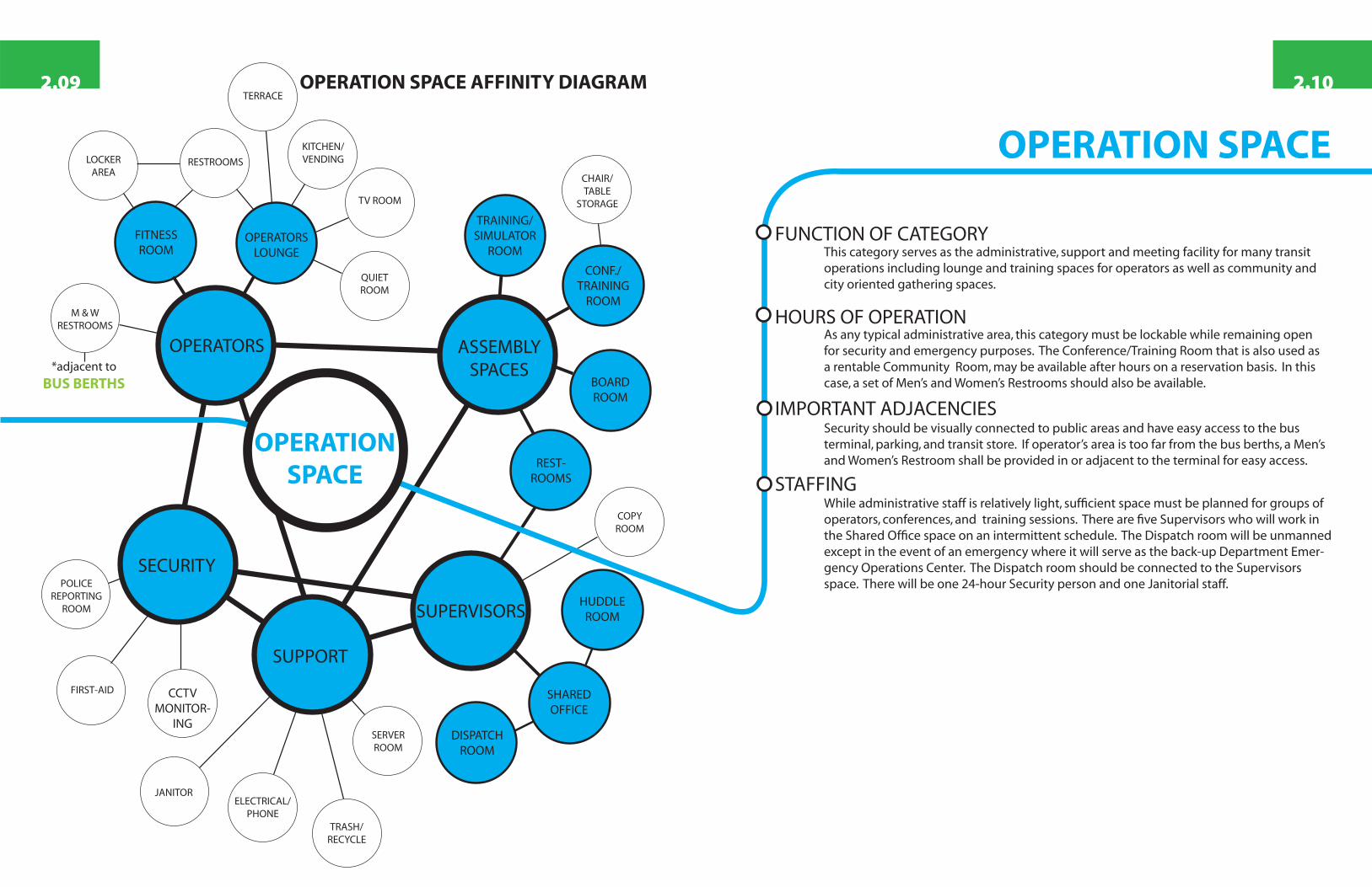
OPERATION SPACE AFFINITY DIAGRAM
OPERATION SPACE
Security should be visually connected to public areas and have easy access to the bus terminal, parking, and transit store. If operator’s area is too far from the bus berths, a Men’s and Women’s Restroom shall be provided in or adjacent to the terminal for easy access.
IMPORTANT ADJACENCIES
FUNCTION OF CATEGORYThis category serves as the administrative, support and meeting facility for many transit operations including lounge and training spaces for operators as well as community and city oriented gathering spaces.
HOURS OF OPERATIONAs any typical administrative area, this category must be lockable while remaining open for security and emergency purposes. The Conference/Training Room that is also used as a rentable Community Room, may be available after hours on a reservation basis. In this case, a set of Men’s and Women’s Restrooms should also be available.
While administrative staff is relatively light, suffi cient space must be planned for groups of operators, conferences, and training sessions. There are fi ve Supervisors who will work in the Shared Offi ce space on an intermittent schedule. The Dispatch room will be unmanned except in the event of an emergency where it will serve as the back-up Department Emer-gency Operations Center. The Dispatch room should be connected to the Supervisors space. There will be one 24-hour Security person and one Janitorial staff.
STAFFING
OPERATIONSPACE
2.102.09

PARKING
PASSENGERAREAS
LOADING/UNLOADING
MISC
EMPLOYEE
DEDICATED
REGULAR
PUBLIC
REGULARDEDICATED
TVMs
SEATING
LANDSCAPED PLAZAS
COVEREDTERMINAL
BUSES
LAYOVER SPACES
KISS AND RIDE DROP-
OFF
BICYCLE STORAGE
OTHER AGENCIES
ELECTRIC CAR CHARGING
STATION
TRANSIT SITE AFFINITY DIAGRAM
TRANSIT SITE
The Transit Terminal and Kiss-and-Ride Drop-Off should be easily accessed from the Transit Store, Transit Center Lobby and TVM areas. A restroom shall be provided in close proximity to the berths for the operators on short breaks. Each parking area should include regular and dedicated spaces. Dedicated spaces within the Public lot include spaces for: ADA ac-cessible, LEV, & electric vehicle charging. Dedicated spaces within the Employee lot include spaces for: ADA accessible, transit relief vehicle and Police & Sheriff, transit security vehicles, and supervisors vehicles.
IMPORTANT ADJACENCIES
FUNCTION OF CATEGORYThis category represents any function and space related to the Transit Center portion of the site.
HOURS OF OPERATIONThe Passenger Areas are open during standard terminal operating hours. Transit Center parking shall remain open 24-hours.
No full time staff are necessary in this category.
STAFFING
TRANSITSITE
2.122.11

1234
7
5
8
9
12
14
19
22
24
15
23
6
27
30
31
32
11
21
25
05
105
110
110
405
TORRANCE
LOMITA
PALOSVERDES
HARBORCITY
LOANG
LOSANGELES
GARDENA
HAWTHORNE 1
2
5
7
9
Arl
ing
ton
Ave
o Blvd
Skypark Dr.
Mad
iso
n S
t
Plaza Del Amo
Lomita Blvd
Cab
rillo
Ave
Van
Nes
s A
ve
An
za A
ve
Carson St
An
za A
ve
Fig
uer
oa
St
Fig
uer
oa
St
Gardena Blvd
182nd St
Ave
Ing
lew
oo
d A
ve
Prai
rie
Ave
rbo
nn
e A
ve
Mad
ron
a A
ve
Sepulveda Blvd
Artesia Blvd
Rosecrans Ave
Marine Ave
Manhattan Beach Blvd
El Segundo Blvd E
135th St
Redondo Beach Blvd
Haw
tho
rne
Blv
d
190th St
Verm
on
t A
ve
Nor
man
die
Ave
Wes
tern
Ave
Torrance Blvd
Cre
nsh
aw B
lvd
TorranceAirport
HarborFreewayStation
Del AmoMall(See
SystemMap Page)
Chapter 3: Space Needs Program

Qty. Staff
Public SpaceT rans it S tore 2Vo lun teer 1
Tenant SpaceReta il 17
Operation SpaceSupervisors 2Security 1Jan ito r 1
TOTAL STAFF 24
Tenant SpaceCustom ers 108
Operation SpaceAssem bly Spaces 184O pera tors 30
Transit SpacePassengers 480
TOTAL USERS 802
TOTAL STAFF AND USERS 826
Category Facility staffi ng levels are crucial to the planning team when determining number of parking spaces, size of support areas, and developing occupancy levels. The following chart is a sum-mary of the projected full time equivalent (FTE) staffi ng number for each category in ad-dition to a projected number of users of the entire Transit site. The Tenant Space Retail staff projections are just a best estimate and are staff provided by the retail businesses.
Staff Summary
User Summary
826PEOPLE
802
826TOTAL STAFF AND USERS
FTE STAFF
USERS
24
3.023.01

Qty.Staff
Qty.Space
Area(SQ. FT.) Remarks
TRANSIT STORE2 150 Sales Counter Two counters for Torrance T rans it Sa les : O pera tion hours ta ilo red to the needs of the cus tom ers .1 50 Volunteer S ta tion Reserved for Future Expans ion
100 M erchand ise T rans it M erchand ise , approx 100 sq. ft.; poss ib le k iosk /a lcove setup w ith counters50 M erchand ise S torage Could be separa te room or c loset/cab ine t space.50 TVM 's T icke t Vend ing M ach ines- hard w ired . Need for m ach ines in two locations : 2 outs ide of T rans it S tore , 2 on bus
p la tfo rm ; fu ture load ing of TAP cards . P rovide fu ture condu it fo r expans ion m ach ines ; un iversa l fa re sys temexpandab le
3 400 TOTAL TRANSIT STORE
LOBBY2400 Lobby/W aiting area Real tim e schedu le d isp lays , em ergency phone (no pub lic phones), m ust be ab le to c lose during off hours220 M en 's Pub lic Restroom 3 W ater C loset/3 U rina ls /2 Lav--share w ith RETA IL , baby chang ing s ta tion ; low flow fix tu res , vanda l proof350 W om en's Pub lic Restroom 11 W ater C loset/2 Lav--share w ith RETA IL , baby chang ing s ta tion ; low flow fix tu res , vanda l proof120 Fam ily Pub lic Restroom 1 W ater C loset/1 Lav--share w ith RETA IL , baby chang ing s ta tion ; low flow fix tu res , vanda l proof
3090 TOTAL LOBBY
3 3490 TOTAL PUBLIC SPACE
Public Space- Area Description
PUBLIC SPACE PROGRAM
3,490 SQ. FT.
3
3.043.03

TENANT SPACE PROGRAMQty.Staff
Qty.Space
Area(SQ. FT.) Remarks
COMMERCIAL USES
15 TBD 3000 Tenant spacesPoss ib le re ta il, food & beverage uses. Am ount o f each subd iv ided area to be determ ined by m arket ana lys is .Q uantity o f s ta ff es tim ated for re ta il & coffee shop type use.O pen to A ll: T rans it riders and outs ide pub lic access from both ins ide the center and outs ide , or s ignedappropria te ly to be vis ib le from the outs ide . Des ign to cons ider poss ib le em pty space if re ta il spaces are notoccup ied.
2 300 B icyc le Shop Priva te ly opera ted . M erchand ise , Repa ir, Renta l, & S torage
17 3300 TOTAL TENANT SPACE
Tenant Space- Area Description
3,300SQ. FT.
17
3.063.05

Qty.Staff
Qty.Space
Area(SQ. FT.) Remarks
OPERATORS450 O pera tors Lounge Account fo r 30+ opera tors ; seating350 TV Room G lass door, Seating200 Q uie t Room G lass door, Seating500 Pantry M ultip le m icrowaves (1 per 20 peop le), s ink w / d isposa l, re frigera tor100 Vend ing Snacks , Coffee , D rinks , Ice M ach ine300 Exerc ise Room200 Lounge M en 's Restroom 2 W Cs/1 U rina l/1 Lav. Inc ludes separa te shower and chang ing area200 Lounge W om en's Restroom 3 W Cs/1 Lav. Inc ludes separa te shower and chang ing area80 M en 's Room (Adjacent to Bus Term ina l) 1 W C , 1 Lav. Necessary if Lounge M en 's Restroom s are not d irec tly ad jacent to Bus Term ina l)80 W om en 's Room (Adjancent to Bus Term ina l) 1 W C , 1 Lav. Necessary if Lounge W om en's Restroom s are not d irec tly ad jacent to Bus Term ina l)
0 2460 TOTAL OPERATORS
ASSSEMBLY2250 Conference/T ra in ing Room 150 person capac ity, d iv idab le ; used by C ity & Pub lic ; separa ted c ircu la tion from opera tions areas ;
dropdown screens, A /V , W hite boards , pro jec tors , pub lic address sys tem connector, L igh ting Contro l,TV .
150 Chair/Tab le S torage D irec t or ind irec t access to Conference/T ra in ing Room450 Board Room 25-30 person capac ity; 1 la rge conference tab le , A /V , TV , W hite Boards200 T ra in ing /S im ula tor Room 1 sim ula tor m ach ine , 1 fare box tra iner, 1 rad io tra iner, 1 W /C lift tra iner
0 3050 TOTAL ASSEMBLY
SUPERVISORS2 600 Shared O pen O ffice 4 works ta tions ; DVR sta tion w / lockab le cab ine t; P rin te r A rea; operab le w indows to outs ide , under-
floor a ir d is tribu tion poss ib le , dayligh ting .65 Hudd le Room G lass door, wh ite boards150 D ispatch Room Dept. Back -up Em ergency O p. Center, Phone L ines , Record CCTV , Com puter eqp. ex tens ions .
Extens ion of Supervisor's o ffice . Unm anned except during an em ergency.200 M en 's Restroom s 1 W C /1 U rina l/1 Lav. Poss ib le share w ith Assem bly space if secured; low flow fix tu res .300 W om en's Restroom 4 W Cs/1 Lav. Poss ib le share w ith Assem bly space if secured; low flow fix tu res .
2 1315 TOTAL SUPERVISORS
SUPPORT100 Copy Room DVR , Paper, and F ile S torage150 T rash/Recyc ling Locate ins ide or outs ide . Separa te path of trave l from pub lic and trans it a reas .
1 2 100 Jan ito r C lean ing Supp lies , Restroom supp lies , Jan ito r's s ink , S torage for: floor buffe rs , pressure washers ,water broom storage.
200 Server Room Need fina l s ize from CO T IT Dept; des ign to a llow for expans ion775 E lec trica l/Phone
1 1425 TOTAL SUPPORT
SECURITY
1300 Security O ffice G round F loor; V isua lly and phys ica lly connect to te rm ina l, park ing , and T rans it S tore . M on ito ring of
CCTV shared space for po lice to w rite reports ; firs t-a id s ta tion .1 300 TOTAL SECURITY
4 8550 TOTAL OPERATIONS SPACE
Operations Space- Area Description
OPERATIONS SPACE PROGRAM
8,550 SQ. FT.
4
3.083.07
TRANSIT SITE PROGRAMQty.
SpaceArea
(Sq. Ft.) Remarks
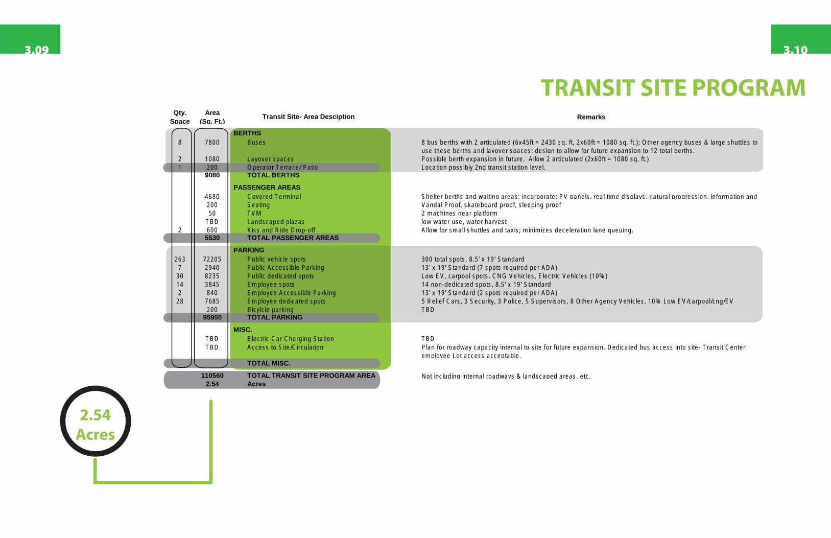
BERTHS8 7800 Buses 8 bus berths w ith 2 articu la ted (6x45ft = 2430 sq. ft, 2x60ft = 1080 sq. ft.); O ther agency buses & large shuttles to
use these berths and layover spaces; des ign to a llow for fu tu re expans ion to 12 to ta l berths .2 1080 Layover spaces Poss ib le berth expans ion in fu ture . A llow 2 articu la ted (2x60ft = 1080 sq. ft.)1 200 O pera tor Terrace/ Patio Location poss ib ly 2nd trans it s ta tion leve l.
9080 TOTAL BERTHS
PASSENGER AREAS4680 Covered Term ina l She lte r berths and waiting areas ; incorpora te : PV pane ls , rea l tim e d isp lays , na tura l p rogress ion , in fo rm ation and200 Seating Vanda l P roof, ska teboard proof, s leep ing proof50 TVM 2 m ach ines near p la tfo rm
TBD Landscaped p lazas low water use, water harves t2 600 K iss and R ide D rop-o ff A llow for sm all shuttles and tax is ; m in im izes dece lera tion lane queu ing .
5530 TOTAL PASSENGER AREAS
PARKING263 72205 Pub lic veh ic le spots 300 to ta l spots , 8 .5 ' x 19 ' S tandard7 2940 Pub lic Access ib le Park ing 13 ' x 19 ' S tandard (7 spots requ ired per ADA)30 8235 Public ded ica ted spots Low EV, carpoo l spots , CNG Vehic les , E lec tric Veh ic les (10% )14 3845 Em ployee spots 14 non-ded ica ted spots , 8 .5 ' x 19 ' S tandard2 840 Em ployee Access ib le Park ing 13 ' x 19 ' S tandard (2 spots requ ired per ADA)28 7685 Em ployee ded ica ted spots 5 Relie f Cars , 3 Security, 3 Po lice , 5 Supervisors , 8 O ther Agency Veh ic les , 10% Low EV/carpoo l/cng/EV
200 B icylc le park ing TBD95950 TOTAL PARKING
MISC.TBD E lec tric Car Charg ing S ta tion TBDTBD Access to S ite /C ircu la tion P lan for roadway capac ity in te rna l to s ite fo r fu ture expans ion . Ded ica ted bus access in to s ite - T rans it Center
em ployee Lot access acceptab le .TOTAL MISC.
110560 TOTAL TRANSIT SITE PROGRAM AREA Not inc lud ing in te rna l roadways & landscaped areas , e tc .2.54 Acres
Transit Site- Area Desciption
2.54Acres
3.103.09

1234
7
5
8
9
12
14
19
22
24
15
23
6
27
30
31
32
11
21
25
05
105
110
110
405
TORRANCE
LOMITA
PALOSVERDES
HARBORCITY
LOANG
LOSANGELES
GARDENA
HAWTHORNE 1
2
5
7
9
Arl
ing
ton
Ave
o Blvd
Skypark Dr.
Mad
iso
n S
t
Plaza Del Amo
Lomita Blvd
Cab
rillo
Ave
Van
Nes
s A
ve
An
za A
ve
Carson St
An
za A
ve
Fig
uer
oa
St
Fig
uer
oa
St
Gardena Blvd
182nd St
Ave
Ing
lew
oo
d A
ve
Prai
rie
Ave
rbo
nn
e A
ve
Mad
ron
a A
ve
Sepulveda Blvd
Artesia Blvd
Rosecrans Ave
Marine Ave
Manhattan Beach Blvd
El Segundo Blvd E
135th St
Redondo Beach Blvd
Haw
tho
rne
Blv
d
190th St
Verm
on
t A
ve
Nor
man
die
Ave
Wes
tern
Ave
Torrance Blvd
Cre
nsh
aw B
lvd
TorranceAirport
HarborFreewayStation
Del AmoMall(See
SystemMap Page)
Chapter 7: Master Plan

Introduction
The Final Master Plan was developed from the nine schemes prepared during the on-site design charrette and subsequent working sessions with the City. The Plan responds to the Transit Cen-ter operational and environmental needs as well as the planning required to provide usable and marketable Transit Oriented Development (TOD) parcels. In addition, the plan addresses buildable areas used for future expansion.
As noted earlier, the Master Plan for the Transit Center & site was developed through an interactive process with representatives from the user groups and senior management from the City Depart-ments. This input resulted in a layout diagram that satisfi es the functional and operational needs of the different uses that comprise the Transit Center and site, while taking into consideration a num-ber of other planning issues.
The following parameters have infl uenced the fi nal site plan:
- Optimizing visibility from Crenshaw Blvd. to the Transit Center.- Separation of transportation modes within the site.- Providing area for expansion for the bus terminal and Transit Center Parking.- Providing areas for fi re truck access.- Creating visible outdoor pedestrian spaces for transit customers.- Creating a fl exible outdoor spaces for transit customers and outdoor events.- Create viable Transit Oriented Development parcels.- Developing an extension of W 208th St. into the site to allow for site access and possible future access for the neighboring property to the north.- Optimizing a balance of building orientation and outdoor areas for environ-mental considerations (natural lighting & ventilation).
7.027.01

Site Plan
In this plan, and in all of the scenarios studied, W 208th Street has been extended west of its inter-section with Crenshaw Blvd. It was determined that this is the optimal site access for busses and heavier vehicles, such as delivery trucks that may be accessing the Transit Oriented Development parcels. A cul-de-sac is provided at the west end of the street where access to the western TOD parcel and to the Transit Center bus loop is located.
As mentioned, one of the key parameters for safety is the separation of transportation modes within the site. The site is organized with two vehicle access points with modal separation. The northern access point from the extension of W 208th St. is reserved for busses only and connects to the bus terminal loop located to the west of the Transit Center building.
The second access point is reserved for Transit Center employee and user vehicles and also to ac-cess the kiss-n-ride drop-off located in-front of the Transit Center plaza. This second access point is located mid-block on Crenshaw Blvd. between the signalized intersection at W 208th St. and the existing rail overpass. The intersection with Crenshaw Blvd. is a three-way signalized intersection with possible extension to the property along the east (as it is currently being re-developed). Both intersections are located to allow proper distance between traffi c signals to allow for vehicle queu-ing on Crenshaw Blvd. and to allow for full acceleration/deceleration lanes along the Crenshaw site frontage.
The Transit Center building is located middle of the property in the north-south direction, posi-tioned with the entry plaza facing the Crenshaw Blvd. entry. The bulk of the building is oriented somewhat in the east-west direction to optimized environmental factors for internal day-lighting. The plaza and building arrangement creates and entry focal point into the plaza towards the bus terminal bridge and vertical circulation core. This arrangement allows us to architecturally express the main purpose of the Transit Center, quick and safe access to the bus terminal and possible future rail platform beyond.
A Transit Plaza is created above grade that allows users to access the Transit Center building and bridges to the Transit Terminal and the Transit Parking garage. The plaza is located above grade for the following reasons: - Maximizes visibility of the plaza from Crenshaw Blvd. - Creates a safe platform above the transit site that allows users and security to view the entry road, bus terminal, and overall campus. - Allows for pedestrian and bus separation at the bus terminal. The bridge from the transit plaza to the terminal is accessed without the need for interior vertical circulation and is created through ramps and stairs in the plaza entry. A vertical circulation core is located in the middle of the bus platform and initially provides stair and elevator access to the terminal below. - Allows for future direct connection to the terminal bridge from the proposed Metro rail extension platform. - Creates a direct connection through a bridge to the Transit Garage. This bridge allows for safe separation of pedestrians from the garage and service entry driveway. This bridge will also allow for an architectural expression along the length of the Transit Garage. - Allows for the possibility for operations space located below the plaza and accessed from the bus terminal or exterior of the building (I.E. operator’s access, security access, service access).
The Transit Garage is located at the extreme south end of the property and is oriented parallel to the existing rail ROW and west property line. This portion of the property was deemed ideal for the garage location for the following reasons: - Provides visibility from Crenshaw Blvd. to the garage which shows off the parking as an accessible site amenity. - Allows for a direct pedestrian connection along the garage to the Transit Center plaza which also serves as a view corridor from Crenshaw. - Reserves more northern part of the site for TOD uses.
The bus terminal loop is located south west of the Transit Center building and plaza between the building and the property boundary. The loop is also located north west of the Transit Garage. Access to the bus loop is from the W 208th St. extension to the north through an access driveway. This driveway is two-way and connects to the north end of the bus loop. Busses circulate clockwise around the center island and load and unload in the provided bus berths on the island. The initial project will include eight active bus berths, two of which allow for 60-foot articulating busses. Par-allel bus layover spaces are located adjacent to the transit building. Future expansion is allowed by extending the bus loop and island to the south towards the Transit Garage. Enough room re-mains from the initial project to allow the terminal to expand to 12-total bus berths, three of which allow for 60-foot articulating busses.
7.047.03
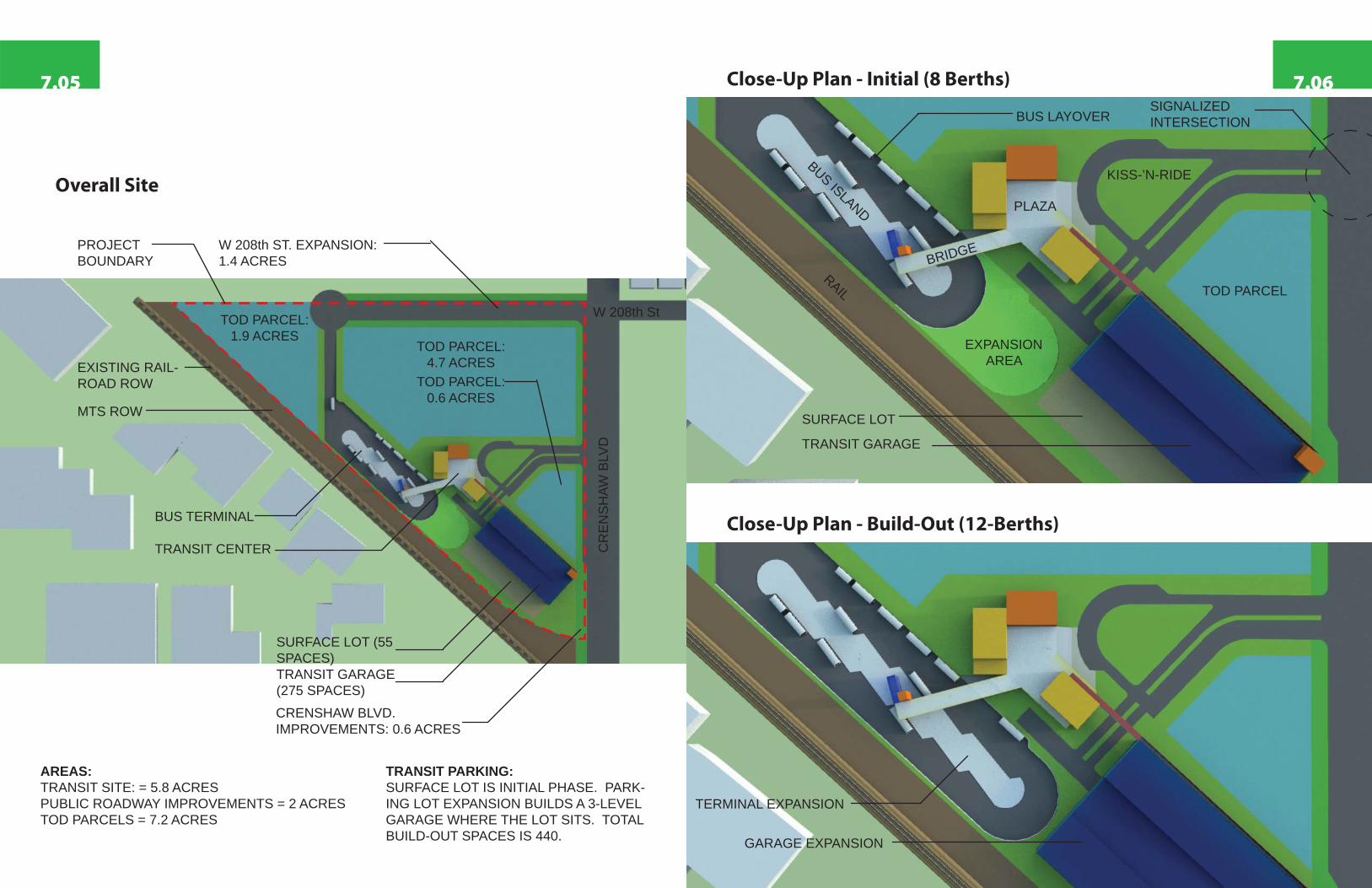
Overall Site
Close-Up Plan - Initial (8 Berths)
Close-Up Plan - Build-Out (12-Berths)
W 208th St
CR
EN
SH
AW B
LVD
TOD PARCEL:1.9 ACRES
TOD PARCEL:4.7 ACRES
TOD PARCEL
EXPANSION AREAEXISTING RAIL-
ROAD ROW
MTS ROW
PROJECT BOUNDARY
BUS TERMINAL
TRANSIT CENTER
TRANSIT GARAGE (275 SPACES)
TRANSIT GARAGE
SURFACE LOT (55 SPACES)
TRANSIT PARKING:SURFACE LOT IS INITIAL PHASE. PARK-ING LOT EXPANSION BUILDS A 3-LEVEL GARAGE WHERE THE LOT SITS. TOTAL BUILD-OUT SPACES IS 440.
TOD PARCEL:0.6 ACRES
KISS-’N-RIDE
PLAZA
BRIDGE
BUS ISLAND
BUS LAYOVER
RAIL
SURFACE LOT
CRENSHAW BLVD. IMPROVEMENTS: 0.6 ACRES
W 208th ST. EXPANSION: 1.4 ACRES
AREAS:TRANSIT SITE: = 5.8 ACRESPUBLIC ROADWAY IMPROVEMENTS = 2 ACRESTOD PARCELS = 7.2 ACRES
GARAGE EXPANSION
TERMINAL EXPANSION
SIGNALIZED INTERSECTION
7.067.05

Bird’s Eye View - Looking North Bird’s Eye View - Looking South
Looking Along the Southern Crenshaw Entry
7.087.07

Crenshaw Blvd. Entry Bridge
7.107.09
Kiss-’n-Ride Bus Entry