torque-dependent remodeling of the bacterial flagellar motor
TRANSCRIPT

BIO
PHYS
ICS
AN
DCO
MPU
TATI
ON
AL
BIO
LOG
Y
Torque-dependent remodeling of the bacterialflagellar motorNavish Wadhwaa,b,1, Rob Phillipsc,d, and Howard C. Berga,b
aDepartment of Molecular and Cellular Biology, Harvard University, Cambridge, MA 02138; bRowland Institute at Harvard, Harvard University, Cambridge,MA 02142; cDepartment of Physics, California Institute of Technology, Pasadena, CA 91125; and dDivision of Biology and Biological Engineering,California Institute of Technology, Pasadena, CA 91125
Edited by Steven M. Block, Stanford University, Stanford, CA, and approved May 6, 2019 (received for review March 15, 2019)
Multisubunit protein complexes are ubiquitous in biology andperform a plethora of essential functions. Most of the scientific lit-erature treats such assemblies as static: their function is assumedto be independent of their manner of assembly, and their struc-ture is assumed to remain intact until they are degraded. Recentobservations of the bacterial flagellar motor, among others, bringthese notions into question. The torque-generating stator unitsof the motor assemble and disassemble in response to changesin load. Here, we used electrorotation to drive tethered cellsforward, which decreases motor load, and measured the result-ing stator dynamics. No disassembly occurred while the torqueremained high, but all of the stator units were released when themotor was spun near the zero-torque speed. When the electroro-tation was turned off, so that the load was again high, stator unitswere recruited, increasing motor speed in a stepwise fashion. Amodel in which speed affects the binding rate and torque affectsthe free energy of bound stator units captures the observedtorque-dependent stator assembly dynamics, providing a quanti-tative framework for the environmentally regulated self-assemblyof a major macromolecular machine.
regulated self-assembly | bacterial flagellar motor |multisubunit complex | molecular motor
B iology is replete with examples of macromolecular pro-tein complexes, which consist of smaller components that
self-assemble to form functional molecular machines (1). Suchmachines perform essential biological functions across life forms,such as protein synthesis, ATP production, DNA replication, andintracellular transport (2–5). The assembly of such complexes isknown to be regulated at the level of gene transcription and pro-tein synthesis, but little is known about the factors that controlthe fate of the assembly once the mature protein subunits entertheir target space (cytoplasm, membrane, or cell wall). Typi-cally, assembled protein complexes are assumed to be static, withfunctions independent of their mode of assembly.
A growing body of literature on subunit exchange in proteincomplexes is bringing this worldview into question (6). Amongthese, the bacterial flagellar motor, e.g., of Escherichia coli(Fig. 1A), has emerged as a prime example of a macromolecularcomplex whose assembly is dynamically modulated in a func-tionally relevant manner and serves as a case study in which aquantitative description of the process can be rigorously laid out.Self-assembled at the cell wall from over 20 different kinds ofproteins, this motor propels cells through fluids by rotating extra-cellular helical filaments (7, 8). The part of the motor embeddedin the inner membrane is called the rotor. Torque-generatingstator units (each consisting of four MotA and two MotB pro-teins) bind to the peptidoglycan layer and apply torque on therotor (9, 10). Up to 11 stator units work together to drive themotor and the bound units exchange with an inner membrane-embedded pool of unbound units (11–13). The motor adapts tochanges in the mechanical load by changing the number of sta-tor units, thereby matching output with demand (14–16). Thisdynamic self-assembly enables the cell to conserve resources.For example, when motors are first assembled and flagellar
filaments are short, the torque required to spin them can be sup-plied by a small number of stator units, each of which passesthe same number of protons per revolution (assuming tight cou-pling). A larger number of units waste energy without improvingfunction.
Here we report the precise dependence of stator stoichiom-etry on torque over the full range of operating conditions, atsteady state as well as after sudden changes in motor torque.To control the torque, we used electrorotation (Fig. 1B), inwhich a fast-rotating electric field applies external torque ona tethered cell (17, 18). Cells were tethered to sapphire viaa short sticky-filament stub, and the rotating electric field wasapplied using an apparatus developed earlier (Materials andMethods). When the external field was turned on, the cell rapidlysped up. We measured the dynamics of stator remodeling fol-lowing a change in motor rotation rate from low speeds ofabout 10 Hz to high speeds ranging from 50 Hz to 300 Hz.The torque produced by the motor over these speeds rangedfrom high torque at low speeds to zero torque (and occasion-ally negative torque) at 300 Hz. The motor released all itsstator units at speeds near the zero-torque speed. When theexternal field was turned off, the external load returned to alarge value, and the speed increased in a stepwise manner, asnew stator units were recruited. We used these measurementsand the tools of statistical physics to develop a model for thetorque-dependent stator assembly, which captured the observeddynamics.
Significance
The molecular machines that carry out important biologicalfunctions in living cells are often made from smaller unitsthat self-assemble inside the cell. Despite decades of researchinto the function of assembled molecular complexes, little isknown about how their assembly itself is regulated to accom-modate varying environmental conditions. We measure howthe assembly of the bacterial flagellar motor depends on itsoperational parameters, such as speed and torque. Based onthese measurements, we use tools from statistical physicsto construct a model for the regulated self-assembly, whichlargely captures the observed kinetics. This work advances ourunderstanding of how interactions between protein subunitscan be tuned by external stimuli to functionally control theformation of macromolecular assemblies.
Author contributions: N.W. and H.C.B. designed research; N.W. performed research; R.P.and H.C.B. contributed new reagents/analytic tools; N.W. analyzed data; and N.W. andH.C.B. wrote the paper.y
The authors declare no conflict of interest.y
This article is a PNAS Direct Submission.y
Published under the PNAS license.y1 To whom correspondence may be addressed. Email: navish [email protected]
This article contains supporting information online at www.pnas.org/lookup/suppl/doi:10.1073/pnas.1904577116/-/DCSupplemental.y
www.pnas.org/cgi/doi/10.1073/pnas.1904577116 PNAS Latest Articles | 1 of 6
A B
C
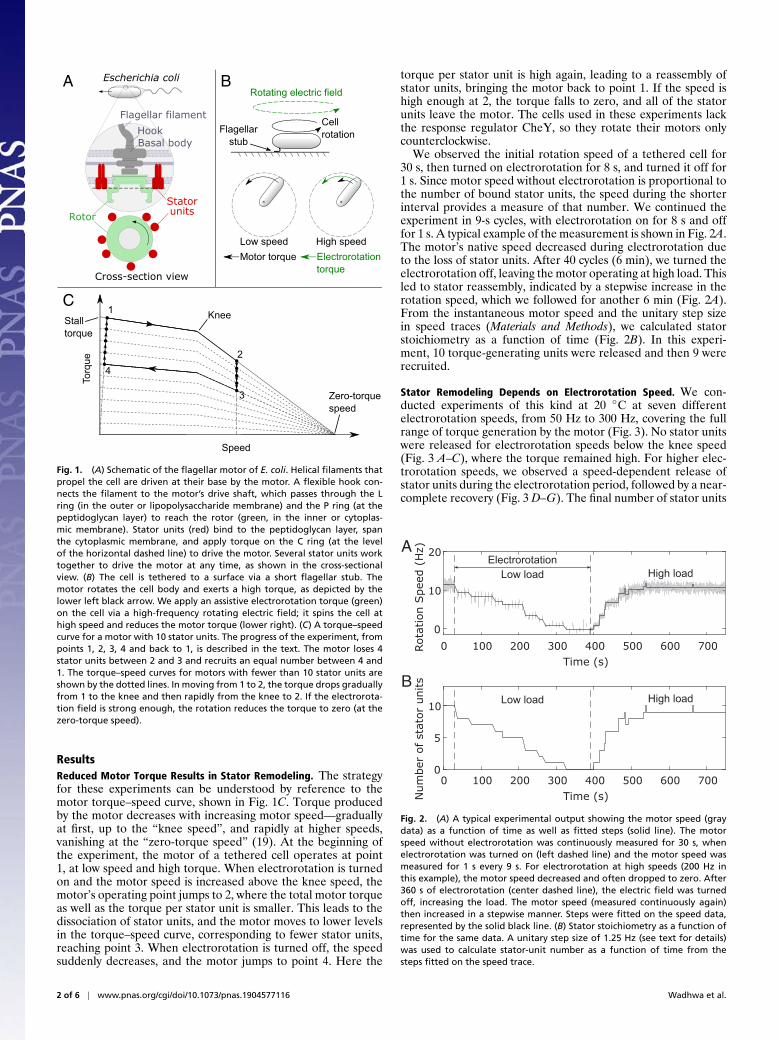
Fig. 1. (A) Schematic of the flagellar motor of E. coli. Helical filaments thatpropel the cell are driven at their base by the motor. A flexible hook con-nects the filament to the motor’s drive shaft, which passes through the Lring (in the outer or lipopolysaccharide membrane) and the P ring (at thepeptidoglycan layer) to reach the rotor (green, in the inner or cytoplas-mic membrane). Stator units (red) bind to the peptidoglycan layer, spanthe cytoplasmic membrane, and apply torque on the C ring (at the levelof the horizontal dashed line) to drive the motor. Several stator units worktogether to drive the motor at any time, as shown in the cross-sectionalview. (B) The cell is tethered to a surface via a short flagellar stub. Themotor rotates the cell body and exerts a high torque, as depicted by thelower left black arrow. We apply an assistive electrorotation torque (green)on the cell via a high-frequency rotating electric field; it spins the cell athigh speed and reduces the motor torque (lower right). (C) A torque–speedcurve for a motor with 10 stator units. The progress of the experiment, frompoints 1, 2, 3, 4 and back to 1, is described in the text. The motor loses 4stator units between 2 and 3 and recruits an equal number between 4 and1. The torque–speed curves for motors with fewer than 10 stator units areshown by the dotted lines. In moving from 1 to 2, the torque drops graduallyfrom 1 to the knee and then rapidly from the knee to 2. If the electrorota-tion field is strong enough, the rotation reduces the torque to zero (at thezero-torque speed).
ResultsReduced Motor Torque Results in Stator Remodeling. The strategyfor these experiments can be understood by reference to themotor torque–speed curve, shown in Fig. 1C. Torque producedby the motor decreases with increasing motor speed—graduallyat first, up to the “knee speed”, and rapidly at higher speeds,vanishing at the “zero-torque speed” (19). At the beginning ofthe experiment, the motor of a tethered cell operates at point1, at low speed and high torque. When electrorotation is turnedon and the motor speed is increased above the knee speed, themotor’s operating point jumps to 2, where the total motor torqueas well as the torque per stator unit is smaller. This leads to thedissociation of stator units, and the motor moves to lower levelsin the torque–speed curve, corresponding to fewer stator units,reaching point 3. When electrorotation is turned off, the speedsuddenly decreases, and the motor jumps to point 4. Here the
torque per stator unit is high again, leading to a reassembly ofstator units, bringing the motor back to point 1. If the speed ishigh enough at 2, the torque falls to zero, and all of the statorunits leave the motor. The cells used in these experiments lackthe response regulator CheY, so they rotate their motors onlycounterclockwise.
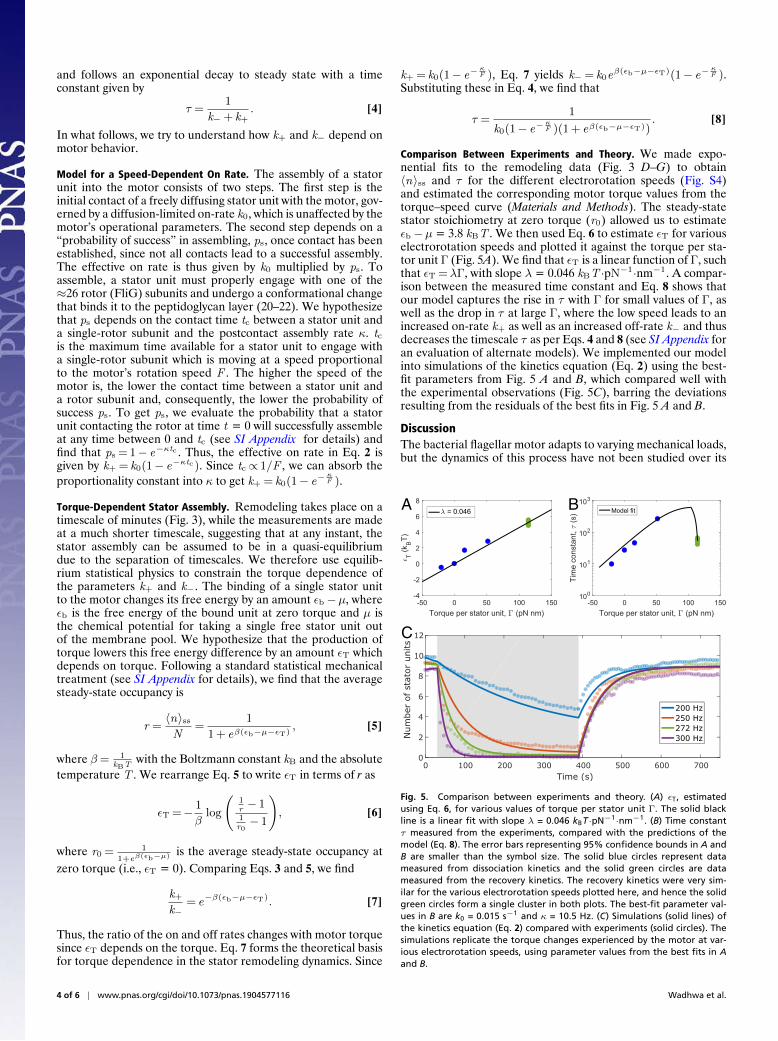
We observed the initial rotation speed of a tethered cell for30 s, then turned on electrorotation for 8 s, and turned it off for1 s. Since motor speed without electrorotation is proportional tothe number of bound stator units, the speed during the shorterinterval provides a measure of that number. We continued theexperiment in 9-s cycles, with electrorotation on for 8 s and offfor 1 s. A typical example of the measurement is shown in Fig. 2A.The motor’s native speed decreased during electrorotation dueto the loss of stator units. After 40 cycles (6 min), we turned theelectrorotation off, leaving the motor operating at high load. Thisled to stator reassembly, indicated by a stepwise increase in therotation speed, which we followed for another 6 min (Fig. 2A).From the instantaneous motor speed and the unitary step sizein speed traces (Materials and Methods), we calculated statorstoichiometry as a function of time (Fig. 2B). In this experi-ment, 10 torque-generating units were released and then 9 wererecruited.
Stator Remodeling Depends on Electrorotation Speed. We con-ducted experiments of this kind at 20 ◦C at seven differentelectrorotation speeds, from 50 Hz to 300 Hz, covering the fullrange of torque generation by the motor (Fig. 3). No stator unitswere released for electrorotation speeds below the knee speed(Fig. 3 A–C), where the torque remained high. For higher elec-trorotation speeds, we observed a speed-dependent release ofstator units during the electrorotation period, followed by a near-complete recovery (Fig. 3 D–G). The final number of stator units
0 100 200 300 400 500 600 700Time (s)
0
10
20
Rota
tion
Spe
ed (
Hz)
0 100 200 300 400 500 600 700Time (s)
0
5
10
Num
ber
of s
tato
r un
its
ElectrorotationLow load High load
Low load High load
A
B
Fig. 2. (A) A typical experimental output showing the motor speed (graydata) as a function of time as well as fitted steps (solid line). The motorspeed without electrorotation was continuously measured for 30 s, whenelectrorotation was turned on (left dashed line) and the motor speed wasmeasured for 1 s every 9 s. For electrorotation at high speeds (200 Hz inthis example), the motor speed decreased and often dropped to zero. After360 s of electrorotation (center dashed line), the electric field was turnedoff, increasing the load. The motor speed (measured continuously again)then increased in a stepwise manner. Steps were fitted on the speed data,represented by the solid black line. (B) Stator stoichiometry as a function oftime for the same data. A unitary step size of 1.25 Hz (see text for details)was used to calculate stator-unit number as a function of time from thesteps fitted on the speed trace.
2 of 6 | www.pnas.org/cgi/doi/10.1073/pnas.1904577116 Wadhwa et al.

BIO
PHYS
ICS
AN
DCO
MPU
TATI
ON
AL
BIO
LOG
Y
Fig. 3. (A–G) Stator stoichiometry vs. time for different electrorotation speeds. The solid line represents the average value calculated from all of the cellsdriven at a given electrorotation speed, and the dark shaded region represents the SD. The dashed horizontal line represents the average initial speed. Thelight shaded region represents the period in which electrorotation was used. Sample sizes for A–G were 18, 13, 31, 31, 30, 17, and 22, respectively.
after the electrorotation period as well as the time required forthe disassembly decreased with increasing electrorotation speed.At 200 Hz (Fig. 3D), the average number of stator units wentdown to around five in the 6 min of electrorotation, while for250 Hz (Fig. 3E) the average went down to one after electrorota-tion. At the zero-torque speed of 272 Hz (Fig. 3F) in nearly everymeasurement, all stator units were released by the end of theelectrorotation period. Our setup allowed us to drive the motorabove its zero-torque speed. At 300 Hz, all stator units werereleased rapidly (Fig. 3G). The dynamics of the stator reassem-bly (after electrorotation was turned off) were not affected by theelectrorotation speed.
Clockwise Rotation in the Absence of CheY. Driving the motornear the zero-torque speed also led to an unexpected observa-tion that a counterclockwise-only motor (one deleted for CheY)occasionally switched to clockwise rotation. Clockwise rotationoccurred while the motor’s native speed was very low, presum-ably while being driven by a single stator unit. Fig. 4 showsan extreme example with sustained clockwise rotation. In mostcases, we observed sporadic events of clockwise rotation lasting<1 s during electrorotation off periods.
Kinetics of the Torque-Dependent Stator Assembly. To capture thedynamics of motor remodeling, we wrote a chemical masterequation for the remodeling process
dp(n, t)
dt= (n + 1)k−p(n + 1, t) + (N −n + 1)k+p(n − 1, t)
−nk−p(n, t)− (N −n)k+p(n, t), [1]
which describes how p(n, t), the probability of having n statorunits bound to the motor at time t , changes over time. k+ andk− are on rate and off rate for a single stator unit and N is thetotal number of binding sites. Given a knowledge of how the ratesk+ and k− vary with motor speed and torque, Eq. 1 preciselydescribes the dynamics of stator assembly. Rearranging Eq. 1
(see SI Appendix for details) leads to a kinetics equation for theaverage number of bound stator units,
d〈n〉dt
= k+(N −〈n〉)− k−〈n〉, [2]
with a steady-state solution, written in terms of the averageoccupancy r as
r =〈n〉ssN
=1
1 +k−k+
, [3]
where 〈n〉ss is the average steady-state number of bound units.The time-dependent solution of Eq. 2 for an initial condition〈n〉(0) =n0 is given by 〈n〉(t) = 〈n〉ss + (n0−〈n〉ss)e−(k++k−)t
0 100 200 300 400 500 600 700Time (s)
0
5
10
15
20
Rota
tion
Spe
ed (
Hz)
Fig. 4. Clockwise rotation of the ∆CheY motor: an extreme example ofclockwise rotation of the motor during electrorotation at 250 Hz. In thisexperiment, the motor sustained clockwise rotation (red data points) duringa large part of the electrorotation period (between the two gray dashedlines) and for the first few seconds after electrorotation was turned off.Thereafter the cell stopped momentarily, switched directions, and rotatedcounterclockwise for the rest of the recovery period.
Wadhwa et al. PNAS Latest Articles | 3 of 6
and follows an exponential decay to steady state with a timeconstant given by
τ =1
k−+ k+. [4]
In what follows, we try to understand how k+ and k− depend onmotor behavior.
Model for a Speed-Dependent On Rate. The assembly of a statorunit into the motor consists of two steps. The first step is theinitial contact of a freely diffusing stator unit with the motor, gov-erned by a diffusion-limited on-rate k0, which is unaffected by themotor’s operational parameters. The second step depends on a“probability of success” in assembling, ps, once contact has beenestablished, since not all contacts lead to a successful assembly.The effective on rate is thus given by k0 multiplied by ps. Toassemble, a stator unit must properly engage with one of the≈26 rotor (FliG) subunits and undergo a conformational changethat binds it to the peptidoglycan layer (20–22). We hypothesizethat ps depends on the contact time tc between a stator unit anda single-rotor subunit and the postcontact assembly rate κ. tcis the maximum time available for a stator unit to engage witha single-rotor subunit which is moving at a speed proportionalto the motor’s rotation speed F . The higher the speed of themotor is, the lower the contact time between a stator unit anda rotor subunit and, consequently, the lower the probability ofsuccess ps. To get ps, we evaluate the probability that a statorunit contacting the rotor at time t = 0 will successfully assembleat any time between 0 and tc (see SI Appendix for details) andfind that ps = 1− e−κtc . Thus, the effective on rate in Eq. 2 isgiven by k+ = k0(1− e−κtc). Since tc∝ 1/F , we can absorb theproportionality constant into κ to get k+ = k0(1− e−
κF ).
Torque-Dependent Stator Assembly. Remodeling takes place on atimescale of minutes (Fig. 3), while the measurements are madeat a much shorter timescale, suggesting that at any instant, thestator assembly can be assumed to be in a quasi-equilibriumdue to the separation of timescales. We therefore use equilib-rium statistical physics to constrain the torque dependence ofthe parameters k+ and k−. The binding of a single stator unitto the motor changes its free energy by an amount εb−µ, whereεb is the free energy of the bound unit at zero torque and µ isthe chemical potential for taking a single free stator unit outof the membrane pool. We hypothesize that the production oftorque lowers this free energy difference by an amount εT whichdepends on torque. Following a standard statistical mechanicaltreatment (see SI Appendix for details), we find that the averagesteady-state occupancy is
r =〈n〉ssN
=1
1 + eβ(εb−µ−εT), [5]
where β= 1kBT
with the Boltzmann constant kB and the absolutetemperature T . We rearrange Eq. 5 to write εT in terms of r as
εT =− 1
βlog
(1r− 1
1r0− 1
), [6]
where r0 = 1
1+eβ(εb−µ) is the average steady-state occupancy atzero torque (i.e., εT = 0). Comparing Eqs. 3 and 5, we find
k+k−
= e−β(εb−µ−εT). [7]
Thus, the ratio of the on and off rates changes with motor torquesince εT depends on the torque. Eq. 7 forms the theoretical basisfor torque dependence in the stator remodeling dynamics. Since
k+ = k0(1− e−κF ), Eq. 7 yields k−= k0e
β(εb−µ−εT)(1− e−κF ).
Substituting these in Eq. 4, we find that
τ =1
k0(1− e−κF )(1 + eβ(εb−µ−εT))
. [8]
Comparison Between Experiments and Theory. We made expo-nential fits to the remodeling data (Fig. 3 D–G) to obtain〈n〉ss and τ for the different electrorotation speeds (Fig. S4)and estimated the corresponding motor torque values from thetorque–speed curve (Materials and Methods). The steady-statestator stoichiometry at zero torque (r0) allowed us to estimateεb−µ = 3.8 kBT . We then used Eq. 6 to estimate εT for variouselectrorotation speeds and plotted it against the torque per sta-tor unit Γ (Fig. 5A). We find that εT is a linear function of Γ, suchthat εT =λΓ, with slope λ = 0.046 kBT ·pN−1·nm−1. A compar-ison between the measured time constant and Eq. 8 shows thatour model captures the rise in τ with Γ for small values of Γ, aswell as the drop in τ at large Γ, where the low speed leads to anincreased on-rate k+ as well as an increased off-rate k− and thusdecreases the timescale τ as per Eqs. 4 and 8 (see SI Appendix foran evaluation of alternate models). We implemented our modelinto simulations of the kinetics equation (Eq. 2) using the best-fit parameters from Fig. 5 A and B, which compared well withthe experimental observations (Fig. 5C), barring the deviationsresulting from the residuals of the best fits in Fig. 5 A and B.
DiscussionThe bacterial flagellar motor adapts to varying mechanical loads,but the dynamics of this process have not been studied over its
A B
C
Fig. 5. Comparison between experiments and theory. (A) εT, estimatedusing Eq. 6, for various values of torque per stator unit Γ. The solid blackline is a linear fit with slope λ = 0.046 kBT·pN−1·nm−1. (B) Time constantτ measured from the experiments, compared with the predictions of themodel (Eq. 8). The error bars representing 95% confidence bounds in A andB are smaller than the symbol size. The solid blue circles represent datameasured from dissociation kinetics and the solid green circles are datameasured from the recovery kinetics. The recovery kinetics were very sim-ilar for the various electrorotation speeds plotted here, and hence the solidgreen circles form a single cluster in both plots. The best-fit parameter val-ues in B are k0 = 0.015 s−1 and κ = 10.5 Hz. (C) Simulations (solid lines) ofthe kinetics equation (Eq. 2) compared with experiments (solid circles). Thesimulations replicate the torque changes experienced by the motor at var-ious electrorotation speeds, using parameter values from the best fits in Aand B.
4 of 6 | www.pnas.org/cgi/doi/10.1073/pnas.1904577116 Wadhwa et al.

BIO
PHYS
ICS
AN
DCO
MPU
TATI
ON
AL
BIO
LOG
Y
full range. Previous work measured partial remodeling dynamicsof the stator by manipulating motor load with magnetic beads,but the range of these measurement was limited by the bead sizesand, consequently, stator stoichiometry changed by at most 2–3units (16). We have closed this gap by using tethered cells thatspin their motors counterclockwise, controlling their speeds froma few hertz to 300 Hz by electrorotation. The number of statorunits bound to the motor varied from ≈10 near stall to 0 at zeroload.
We found a systematic effect of motor speed on statorstoichiometry—increasing the speed beyond the knee speed(Fig. 1C) reduced the motor torque, resulting in the release ofstator units. The rate of stator unit release and the steady-statestoichiometry depended on how far beyond the knee speed themotor was driven. This is consistent with the previously proposedcatch-bond mechanism of stator remodeling, in which the disso-ciation rate of stator units increases with decreased motor torque(16, 23). However, we found evidence that the assembly rate ofstator units is speed dependent, based on the fast recovery of sta-tor stoichiometry after electrorotation was turned off. The motorspeed during recovery was very low, due to the high viscous loadof a tethered cell, resulting in elevated on rates for stator bind-ing. This effect was dominant only at very low motor speeds(κ = 10.5 Hz), which is probably why it went unnoticed in pre-vious studies which measured motor output by labeling it withbeads that typically rotate at speeds greater than 50 Hz.
We do not understand the mechanism of the occasional switchto clockwise state in the absence of CheY. It is possible thathigh electrorotation speed temporarily forced the rotor complexinto a clockwise conformation. Physical (24, 25) and genetic (26)changes in the rotor complex can affect switching with or with-out CheY. In wild-type cells, clockwise bias is reduced underlow loads (27) and during stator remodeling from low to highstator unit number (14), making our observation of occasionalclockwise switch at low stator unit number even more surprising.
Electrorotation allowed us to drive the motor at a speed higherthan the zero-torque speed. The torque produced by the sta-tor units is negative at these speeds (17); i.e., the units act asbrakes against the externally imposed rotation. We expected thatthe stator disassembly dynamics at 300 Hz might be similar tothose at 250 Hz, since the motor produces similar magnitude butopposite sign of torque at these two speeds (torque is a linearlydecreasing function of speed near the zero-torque speed). Theresults, however, showed a much more rapid loss of stator units at300 Hz than at any lower electrorotation speeds (Fig. 3). Clearly,the binding of stator units to the motor depends on the directionas well as the magnitude of the torque. This raises a conundrumillustrated in Fig. 6. Motors exist that spin only clockwise, with
A B C
Fig. 6. (A–C) Orientation of the linkage between stator units and peptido-glycan under three conditions: (A) while driving the motor of ∆CheY cellscounterclockwise (CCW), (B) while resisting rotation in ∆CheY cells whenabove the zero-torque speed, and (C) while driving the motor of cells thatspin only clockwise (CW). In each case the linkage, shown by a straight line,is under tension.
torque–speed curves that lack a knee (28). If stator units comeoff the peptidoglycan layer in Fig. 6B (at negative torque), asour results imply, why do they work in Fig. 6C (for clockwisemotors)? They are applying torque in the same direction in Fig. 6B and C and thus require a similar orientation relative to thepeptidoglycan layer, yet they are released in Fig. 6B and retainedin Fig. 6C.
The biological role for load-dependent stator assembly remainsan interesting and open question. Disengaging excess stator unitswhen operating at low required torque would preserve energy, butcould there be a sensory function of stator remodeling as well?In bacteria with multiple stator unit isoforms, load-dependentremodeling likely regulates the stator composition via competi-tive exchange (29–31). Flagellar stators appear to be required forbacterial response to surface contact during a planktonic to sessiletransition (32–35). It is hypothesized that proximity to a surfaceincreases the viscous load on the flagellum, which is sensed by themotor to signal surface contact to downstream processes (36, 37).Recent work has shown that stator units can stimulate the produc-tion of cyclic di-GMP, a known regulatory molecule involved insurface response and biofilm formation (38–40). Similar mecha-nisms could be at play in other bacteria as well. Thus, the dynamicsof load-dependent stator remodeling not only are relevant foradaptive torque production but also might play an important rolein biofilm formation.
Materials and MethodsBacterial Strains and Cultures. E. coli strain HCB986 (a derivative of AW405)was used for all experiments. HCB986 is deleted for the chemotaxis signal-ing protein CheY as well as the flagellin protein FliC and is transformed withplasmid pFD313, expressing sticky FliC. Cells were grown at 33 ◦C in 10 mLT-broth with 100 mg/mL ampicillin (selection marker for pFD313) to OD600 =0.5–0.7. Cells were harvested by centrifuging at 1,200× g for 7 min. The pel-let was resuspended in 1 mL buffer (20 mM TES, 0.1 mM EDTA, pH 7.5), andthe filaments were sheared off by 60 passages through a piece of polyethy-lene tubing (20 cm long, inner diameter 0.58 mm) connecting two syringesvia 23-gauge stub adapters. The cells were washed again and resuspendedin 7 mL buffer.
Flow Cell and Electrodes. The flow cell and the electrode assembly were asdescribed previously (17), except as noted below. The electrode drive circuitscomprised a high-frequency quadrature oscillator run at 2.25 MHz, a set offour amplifiers, and an output transformer. The amplifiers were new, butthe other components dated from 1993 (17). At the beginning of the workdescribed here, for reasons not understood, a significant amount of heatwas generated during electrorotation. This was not acceptable, becauseboth the knee and zero-torque speeds (Fig. 1C) are strongly temperaturedependent (19). We controlled the temperature at 20 ◦C by fitting an annu-lar Peltier element to the lower part of the flow cell, with its cold side inthermal contact with the sapphire window and its hot side in contact witha water jacket. The water jacket was cooled by a circulating water baththat also controlled the temperature of other parts of the microscope. Asmall thermistor close to the sapphire window measured its temperature,and the Peltier current was adjusted using a PID controller (homemade butbased on a Wavelength Electronics MPT5000 module). We used a 20-mMTES buffer, as it produced higher rotation speeds than the 40-mM TES bufferused previously.
Optics. Tethered cells were imaged in phase contrast, with illumination pro-vided by a 12-V tungsten lamp. The diffracted light was expanded into aparallel beam and split into two parts. One part was imaged onto a sCMOScamera (Edge 5.5; PCO-Tech) and the other one onto the linear-graded fil-ter (LGF) apparatus described previously (17). We imaged the tethered cellon the edge of the filters, generating blips once per revolution. The cam-era was useful when the cells rotated slowly and the linear-graded filterswere useful when they rotated rapidly (while electrorotation was off or on,respectively).
Data Acquisition and Analysis. The AC components of the LGF signals wereRC filtered and then passed to a National Instruments data-acquisitionboard (USB6211). Rotation speed of the cell was monitored during an exper-iment by running a fast-Fourier transform on these data. The camera imageswere recorded at 100 frames per second only when the electrorotation field
Wadhwa et al. PNAS Latest Articles | 5 of 6

was off, to record the native rotation of the motor. During postprocessing,we calculated the axis of rotation and the centroid of the cell in every frame,to get the angular displacement of the cell between frames. Multiplying theangular displacement by the frame rate gave rotation speed, which was fil-tered by a median filter of order 15. The rotation speed was fitted with stepsdetermined by an algorithm described previously (14), slightly modified tomanually remove any steps that were visually determined to overfit noise.
Unitary Step Size. To estimate the change in rotation speed of the cell dueto the addition of a single stator unit, we collected all of the recovery-phase steps into a single dataset and analyzed the probability distributionof different step sizes. The data could be fitted by a mixture of two normaldistributions, the first one with a large peak at 1.25 Hz and the second onewith a small peak at 2.6 Hz. We infer from the fitting that the first peakcorresponds to the addition of a single stator unit, while the second peakcorresponds to the addition of two units within a short time span, so thatour algorithm was unable to distinguish them. Thus, we used a step size of1.25 Hz for estimating the stator stoichiometry from the speed traces.
Estimation of the Torque–Speed Curve at 20 ◦C. We derived the torque–speed curve at 20 ◦C from Chen and Berg (19), which reported torque–speed
curves for the strain used here, and from reanalyzed data for the same strainfrom Berg and Turner (17). Chen and Berg conducted their experiments at15.8 ◦C, 17.7 ◦C, and 22.7 ◦C, while Berg and Turner conducted theirs at11.2 ◦C, 16.2 ◦C, and 22.6 ◦C. From their own measurements and a reanaly-sis of Berg and Turner (17), Chen and Berg (19) reported the values of kneespeed, torque at knee speed, and zero-torque speed, at all of these temper-atures. We did a linear regression on these data to obtain a knee speed of127 Hz, a torque at the knee relative to that at stall of 0.91, and a zero-torque speed of 272 Hz. A full suite of stator units produces about 1,260pN nm of torque at stall, a value that is independent of temperature andthe direction of rotation (11, 19). The zero-torque speed is the same whetherone or more stator units drive the motor (41).
ACKNOWLEDGMENTS. We thank Yuhai Tu, Linda Turner, and Jane Kondevfor insightful discussions; Winfield Hill for improvements in the electronics;Siyu He for help with data analysis; and Karen Fahrner for experimentalassistance and advice. We also acknowledge the Marine Biological Labora-tory Physiology course where the theoretical part of this work was initiated.This work was supported by NIH Grant R01 AI016478 (to H.C.B.) and NIHGrant 1R35 GM118043-01 (to R.P.).
1. B. Alberts, The cell as a collection of protein machines: Preparing the next generationof molecular biologists. Cell 92, 291–294 (1998).
2. T. A. Steitz, A structural understanding of the dynamic ribosome machine. Nat. Rev.Mol. Cell Biol. 9, 242–253 (2008).
3. W. Junge, N. Nelson, ATP synthase. Annu. Rev. Biochem. 84, 631–657 (2015).4. T. A. Baker, S. P. Bell, Polymerases and the replisome: Machines within machines. Cell
92, 295–305 (1998).5. R. D Vale, The molecular motor toolbox for intracellular transport. Cell 112, 467–480
(2003).6. S. E. Tusk, N. J. Delalez, R. M. Berry. Subunit exchange in protein complexes. J. Mol.
Biol. 430, 4557–4579 (2018).7. H. C. Berg, R. A. Anderson, Bacteria swim by rotating their flagellar filaments. Nature
245, 380 (1973).8. H. C. Berg, The rotary motor of bacterial flagella. Annu. Rev. Biochem. 72, 19–54
(2003).9. J. Zhou, S. A. Lloyd, D. F. Blair, Electrostatic interactions between rotor and stator in
the bacterial flagellar motor. Proc. Natl. Acad. Sci. U.S.A. 95, 6436–6441 (1998).10. S. Kojima, D. F. Blair, Solubilization and purification of the MotA/MotB complex of
Escherichia coli. Biochemistry 43, 26–34 (2004).11. S. W. Reid et al., The maximum number of torque-generating units in the flagellar
motor of Escherichia coli is at least 11. Proc. Natl. Acad. Sci. U.S.A. 103, 8066–8071(2006).
12. M. C. Leake et al., Stoichiometry and turnover in single, functioning membraneprotein complexes. Nature 443, 355–358 (2006).
13. D. F. Blair, H. C. Berg, Restoration of torque in defective flagellar motors. Science 242,1678–1681 (1988).
14. P. P. Lele, B. G. Hosu, H. C. Berg, Dynamics of mechanosensing in the bacterial flagellarmotor. Proc. Natl. Acad. Sci. U.S.A. 110, 11839–11844 (2013).
15. M. J. Tipping, N. J. Delalez, R. Lim, R. M. Berry, J. P. Armitage, Load-dependentassembly of the bacterial flagellar motor. mBio 4, e00551-13 (2013).
16. A. L. Nord et al., Catch bond drives stator mechanosensitivity in the bacterial flagellarmotor. Proc. Natl. Acad. Sci. U.S.A. 114, 12952–12957 (2017).
17. H. C. Berg, L. Turner, Torque generated by the flagellar motor of Escherichia coli.Biophys. J. 65, 2201–2216 (1993).
18. R. M. Berry, L. Turner, H. C. Berg, Mechanical limits of bacterial flagellar motorsprobed by electrorotation. Biophys. J. 69, 280–286 (1995).
19. X. Chen, H. C. Berg, Torque-speed relationship of the flagellar rotary motor ofEscherichia coli. Biophys. J. 78, 1036–1041 (2000).
20. E. R. Hosking, C. Vogt, E. P. Bakker, M. D. Manson, The Escherichia coli MotAB protonchannel unplugged. J. Mol. Biol. 364, 921–937 (2006).
21. S. Zhu et al., Conformational change in the periplasmic region of the flagellar statorcoupled with the assembly around the rotor. Proc. Natl. Acad. Sci. U.S.A. 111, 13523–13528 (2014).
22. S. Kojima, N. Nonoyama, N. Takekawa, H. Fukuoka, M. Homma, Mutations targetingthe C-terminal domain of flig can disrupt motor assembly in the Na+-driven flagellaof Vibrio alginolyticus. J. Mol. Biol. 414, 62–74 (2011).
23. R. Chawla, K. M. Ford, P. P. Lele, Torque, but not FliL, regulates mechanosensitiveflagellar motor-function. Sci. Rep. 7, 5565 (2017).
24. L. Turner, S. R. Caplan, H. C. Berg, Temperature-induced switching of the bacterialflagellar motor. Biophys. J. 71, 2227–2233 (1996).
25. Y. Tu, The nonequilibrium mechanism for ultrasensitivity in a biological switch:Sensing by Maxwell’s demons. Proc. Natl. Acad. Sci. U.S.A. 105, 11737–11741(2008).
26. T. Nishikino et al., Rotational direction of flagellar motor from the conformation ofFliG middle domain in marine Vibrio. Sci. Rep. 8, 17793 (2018.
27. F. Wang et al., Non-equilibrium effect in the allosteric regulation of the bacterialflagellar switch. Nat. Phys. 13, 710–714 (2017).
28. J. Yuan, K. A. Fahrner, L. Turner, H. C. Berg. Asymmetry in the clockwise and counter-clockwise rotation of the bacterial flagellar motor. Proc. Natl. Acad. Sci. U.S.A. 107,12846–12849 (2010).
29. N. Terahara et al., Load- and polysaccharide-dependent activation of the Na+-typeMotPS stator in the Bacillus subtilis flagellar motor. Sci. Rep. 7, 46081 (2017).
30. A. Paulick et al., Dual stator dynamics in the Shewanella oneidensis MR-1 flagellarmotor. Mol. Microbiol. 96, 993–1001 (2015).
31. S. L. Kuchma et al., Cyclic di-GMP-mediated repression of swarming motility by Pseu-domonas aeruginosa PA14 requires the MotAB stator. J. Bacteriol. 197, 420–430(2015).
32. L. S. Cairns, V. L. Marlow, E. Bissett, A. Ostrowski, N. R. Stanley-Wall, A mechanical sig-nal transmitted by the flagellum controls signalling in Bacillus subtilis. Mol. Microbiol.90, 6–21 (2013).
33. C. M. Lauriano, C. Ghosh, N. E. Correa, K. E. Klose, The sodium-driven flagellar motorcontrols exopolysaccharide expression in Vibrio cholerae. J. Bacteriol. 186, 4864–4874(2004).
34. C. M. Toutain, N. C. Caizza, M. E. Zegans, G. A. O’Toole, Roles for flagellar sta-tors in biofilm formation by Pseudomonas aeruginosa. Res. Microbiol. 158, 471–477(2007).
35. P. I. Watnick, R. Kolter, Steps in the development of a Vibrio cholerae El Tor biofilm.Mol. Microbiol. 34, 586–595 (1999).
36. R. Belas, Biofilms, flagella, and mechanosensing of surfaces by bacteria. TrendsMicrobiol. 22, 517–527 (2014).
37. A. E. Baker, G. A. O’Toole, Bacteria, rev your engines: Stator dynamics regulateflagellar motility. J. Bacteriol. 199, e00088–17 (2017).
38. A. E. Baker et al., Flagellar stators stimulate c-di-GMP production by Pseudomonasaeruginosa. J. Bacteriol, JB.00741-18 (2019).
39. R. Hengge, Principles of c-di-GMP signalling in bacteria. Nat. Rev. Microbiol. 7, 263–273 (2009).
40. C. D. Boyd, G. A. O’Toole, Second messenger regulation of biofilm formation: Break-throughs in understanding c-di-GMP effector systems. Annu. Rev. Cell Dev. Biol. 28,439–462 (2012).
41. B. Wang, R. Zhang, J. Yuan, Limiting (zero-load) speed of the rotary motor ofEscherichia coli is independent of the number of torque-generating units. Proc. Natl.Acad. Sci. U.S.A. 114, 12478–12482 (2017).
6 of 6 | www.pnas.org/cgi/doi/10.1073/pnas.1904577116 Wadhwa et al.